user’s manual model or100 panel mount orp convertercdn2.us.yokogawa.com/or100_im_01.pdf · model...
TRANSCRIPT
User’sManual
IM 12C11A01-01E
Model OR100Panel Mount ORP Converter
IM 12C11A01-01E2nd Edition
i
Safety Precautions
IM 12C11A01-01E
IM 12C11A01-01E2nd Edition: March, 2004 (YK)All Rights Reserved, Copyright © 2003, Yokogawa Electric Corporation
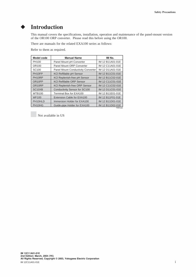
IntroductionThis manual covers the specifications, installation, operation and maintenance of the panel-mount versionof the OR100 ORP converter. Please read this before using the OR100.
There are manuals for the related EXA100 series as follows:
Refer to them as required.
T000.eps
Model code Manual Name IM No.
PH100 Panel Mount pH Converter IM 12 B11A01-01E
OR100 Panel Mount ORP Converter IM 12 C11A01-01E
SC100 Panel Mount Conductivity Converter IM 12 D11A01-01E
PH10FP KCl Refillable pH Sensor IM 12 B11C01-01E
PH10RP KCl Replenish-free pH Sensor IM 12 B11C02-01E
OR10FP KCl Refillable ORP Sensor IM 12 C11C01-01E
OR10RP KCl Replenish-free ORP Sensor IM 12 C11C02-01E
SC10XB Conductivity Sensor for SC100 IM 12 D11C01-01E
WTB100 Terminal Box for EXA100 IM 12 B11E01-01E
WF100 Extension Cable for EXA100 IM 12 B11F01-01E
PH10HLD Immersion Holder for EXA100 IM 12 B11D01-01E
PH10HG Guide-pipe Holder for EXA100 IM 12 B11D02-01E
Not available in US
IM 12C11A01-01Eii
For the safe use of this equipment(1) About This Manual
• This manual should be passed on to the end user.• The contents of this manual are subject to change without prior notice.• The contents of this manual shall not be reproduced or copied, in part or in whole, without permission.• This manual explains the functions contained in this product, but does not warrant that they are suitable
the particular purpose of the user.• Every effort has been made to ensure accuracy in the preparation of this manual. However, when you
realize mistaken expressions or omissions, please contact the nearest Yokogawa Electric representative orsales office.
• This manual does not cover the special specifications. This manual may not be revised when changes inthe hardware or software of the product does not affect the functions or performance of the product.
• If the product is not used in a manner specified in this manual, the safety of this product may beimpaired and the warranty voided.
(2) Safety and Modification Precautions
• Follow the safety precautions in this manual when using the product to ensure protection and safety of thehuman body, the product and the system containing the product.
(3) The following safety symbols are used on the product as well as in this manual.
DANGERThis symbol indicates that an operator must follow the instructions laid out in this manual in order to avoidthe risks, for the human body, of injury, electric shock, or fatalities. The manual describes what specialcare the operator must take to avoid such risks.
WARNINGThis symbol indicates that the operator must refer to the instructions in this manual in order to prevent theinstrument (hardware) or software from being damaged, or a system failure from occurring.
CAUTIONThis symbol gives information essential for understanding the operations and functions.
TipThis symbol gives information that complements the current topic.
SEE ALSOThis symbol identifies a source to be referred to.
This symbol indicates Protective Ground Terminal
This symbol indicates Function Ground Terminal (Do not use this terminal asthe protective ground terminal.)
This symbol indicates Alternating current
iii
Safety Precautions
IM 12C11A01-01E
NOTICE and Cautions• Check specifications
When the instrument arrives, unpack the package with care and check that the instrument has not beendamaged during transportation. In addition, please check that the specification matches the order, andrequired accessories are not missing. Specifications can be checked by the model codes on the nameplate.Refer to Chapter 1.2 Specifications for the list of model codes.
• Details on operation parametersWhen the OR100 panel mount ORP Converter at the user site, it will operate based on the operationparameters (initial data Table 5.1 to 5.3) set before shipping from the factory.Ensure that the initial data is suitable for the operation conditions before conducting analysis. Wherenecessary, set the instrument parameters for appropriate operation. For details of setting data, refer tochapters 4 to 5.When user changes the operation parameters, it is recommended to note down the changed setting data.
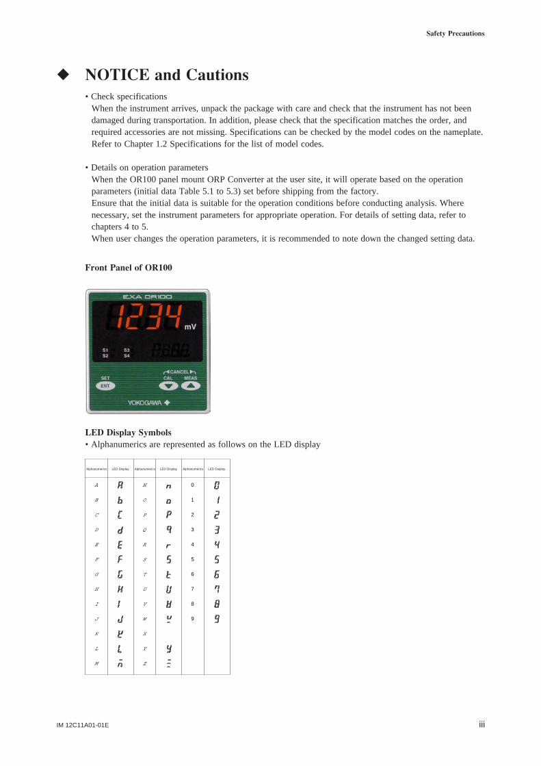
Front Panel of OR100
LED Display Symbols• Alphanumerics are represented as follows on the LED display
9
8
7
6
5
4
3
2
1
0
Z
Y
X
W
V
U
T
S
R
Q
P
O
N
M
L
K
J
I
H
G
F
E
D
C
B
A
Alphanumerics Alphanumerics AlphanumericsLED Display LED Display LED Display
IM 12C11A01-01Eiv
After-sales WarrantyWarranty and ServiceYokogawa products and parts are guaranteed free from defects in workmanship and material under normaluse and service for a period of (typically) 12 months from the date of shipment from the manufacturer.Individual sales organisations can deviate from the typical warranty period, and the conditions of salerelating to the original purchase order should be consulted. Damaged caused by wear and tear, inadequatemaintenance, corrosion, or by the effects of chemical processed are excluded from this warranty coverage.
In the event of warranty claim, the defective goods should be sent (freight paid) to the service department ofthe relevant sales organisation for repair or replacement (at Yokogawa discretion.) The followinginformation must be included in the letter accompanying the returned goods:• Part number, model code and serial number• Original purchase order and date• Length of time in service and a description of the process• Description of the fault, and the circumstances of failure• Process/environmental conditions that may be related to the installation failure of the device• A statement whether warranty or non-warranty service is requested• Complete shipping and billing instructions for return of material, plus the name and phone number of a
contact person who can be reached for further information.
Returned goods that have been in contact with process fluids must be decontaminated/desinfected beforeshipment. Goods should carry a certificate to this effect, for the health and safety of our employees. Materialsafety data sheets should also be included for alll components of the processes to which the equipment hasbeen exposed.
vIM 12C11A01-01E
Contents
Introduction ...................................................................................................................... i
For the safe use of this equipment ................................................................................ ii
NOTICE and Cautions .................................................................................................. iii
After-sales Warranty ..................................................................................................... iv
1. Overview ..................................................................................................................... 1-1
1.1 EXA OR100 ORP converter ........................................................................... 1-11.2 Check the specifications ................................................................................. 1-11.3 Features of the EXA OR100 ORP converter ................................................. 1-11.4 Standard Specifications ................................................................................... 1-2
2. Preparation for Operation ........................................................................................ 2-1
2.1 Unpacking ....................................................................................................... 2-12.2 Choosing an Installation Location .................................................................. 2-12.3 External Dimensions ....................................................................................... 2-22.4 Panel Cutout Dimensions ................................................................................ 2-22.5 Mounting ......................................................................................................... 2-3
3. Wiring .......................................................................................................................... 3-1
3.1 Pulling in Wiring ............................................................................................. 3-13.2 Noise prevention ............................................................................................. 3-13.3 Wiring Terminal Diagram............................................................................... 3-23.4 ORP detector wiring ....................................................................................... 3-43.5 Wiring cable to intermediate terminal box ..................................................... 3-63.6 Output Signal Cable Wiring ........................................................................... 3-63.7 Contact output wiring. .................................................................................... 3-6
3.7.1 Wiring when S1 is used .......................................................................... 3-63.7.2 Wiring for S2 (for two-contact-output case) or S2,
S3 and S4 (four-contact output case) ...................................................... 3-83.8 Power and Ground Wiring .............................................................................. 3-8
4. Overview of Operation Panel ................................................................................... 4-1
4.1 Names and functions of operation panel keys ................................................ 4-14.2 Key Operation ................................................................................................. 4-14.3 Switching Display Screens ............................................................................. 4-24.4 Display Screen Examples ............................................................................... 4-3
4.4.1 Initial display ........................................................................................... 4-34.4.2 Measurement screen ................................................................................ 4-34.4.3 Calibration screen .................................................................................... 4-44.4.4 Setting screen ........................................................................................... 4-4
IM 12C11A01-01Evi
5. Operation .................................................................................................................... 5-1
5.1 Start up ............................................................................................................ 5-15.1.1 Checking wiring ...................................................................................... 5-15.1.2 Start up ORP converter ........................................................................... 5-15.1.3 Data setting .............................................................................................. 5-1
6. Sensor Check and Calibration Procedures ............................................................. 6-1
6.1 Overview of Sensor Checks and Calibration ................................................. 6-16.1.1 Sensor checks .......................................................................................... 6-16.1.2 Calibration (manual calibration) ............................................................. 6-16.1.3 Sensor check solution .............................................................................. 6-1
6.2 Checking Sensors ............................................................................................ 6-16.2.1 Preliminary .............................................................................................. 6-16.2.2 Checking sensors ..................................................................................... 6-1
6.3 Manual Calibration .......................................................................................... 6-26.3.1 Preliminary .............................................................................................. 6-26.3.2 Manual calibration procedures ................................................................ 6-2
6.4 Canceling Calibration ...................................................................................... 6-36.5 If an Error Occurs during Calibration ............................................................ 6-3
6.5.1 Recovering from an Error ....................................................................... 6-36.5.2 Quitting calibration screen ...................................................................... 6-3
7. Maintenance and Cleaning ....................................................................................... 7-1
7.1 Periodic Maintenance ...................................................................................... 7-17.1.1 Sensor cleaning....................................................................................... 7-17.1.2 Checking the KCl solution for ORP sensor ............................................ 7-1
7.2 Preventive Maintenance .................................................................................. 7-17.2.1 ORP converter terminal isolation ............................................................ 7-17.2.2 Checking ORP sensor displays ............................................................... 7-1
8. Troubleshooting .......................................................................................................... 8-1
8.1 Unexpected Value Displayed (Pinpointing the Causes of Problems with Converteror Sensor) ........................................................................................................ 8-1
8.2 Displaying Errors ............................................................................................ 8-38.3 Checks and Corrective Action ........................................................................ 8-3
8.3.1 ORP measurement out of range .............................................................. 8-38.3.2 Converter defective ................................................................................. 8-38.3.3 Calibration asymmetry potential error .................................................... 8-4
Revision Record .................................................................................................................... i
IM 12C11A01-01E 1-1
1. Overview
1. Overview
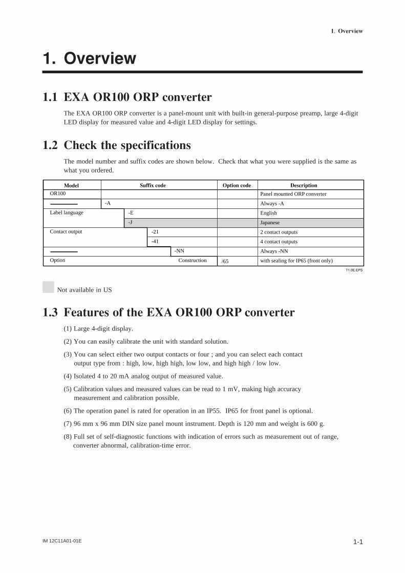
1.1 EXA OR100 ORP converterThe EXA OR100 ORP converter is a panel-mount unit with built-in general-purpose preamp, large 4-digitLED display for measured value and 4-digit LED display for settings.
1.2 Check the specificationsThe model number and suffix codes are shown below. Check that what you were supplied is the same aswhat you ordered.
T1.0E.EPS
Model
-A
-E
-J
-21
-41
-NN
Construction
Panel mounted ORP converter
Always -A
English
Japanese
2 contact outputs
4 contact outputs
Always -NN
with sealing for IP65 (front only)/65
Suffix code Option code Description
OR100
Label language
Contact output
Option
1.3 Features of the EXA OR100 ORP converter(1) Large 4-digit display.
(2) You can easily calibrate the unit with standard solution.
(3) You can select either two output contacts or four ; and you can select each contact output type from : high, low, high high, low low, and high high / low low.
(4) Isolated 4 to 20 mA analog output of measured value.
(5) Calibration values and measured values can be read to 1 mV, making high accuracy measurement and calibration possible.
(6) The operation panel is rated for operation in an IP55. IP65 for front panel is optional.
(7) 96 mm x 96 mm DIN size panel mount instrument. Depth is 120 mm and weight is 600 g.
(8) Full set of self-diagnostic functions with indication of errors such as measurement out of range, converter abnormal, calibration-time error.
Not available in US

IM 12C11A01-01E1-2
1.4 Standard SpecificationsMeasurement: Oxidation-reduction potential (ORP) of a solution
Measuring range: -1500 to 1500 mV
Indication
Display: Digital (LED)
Range: -1500 to 1500 mV
Resolution: 1 mV
Indication items: ORP reading, setting, status
Input signal
ORP input range: -1500 to 1500 mV
Transmission signal output
Number of output points: 1 output, ORP reading only
Output signal: 4 to 20 mA DC, isolated
Load resistance: 600Ω or less
Transmission signal range: Configurable within measuring range (by 100 mV unit),
factory setting: -1500 to 1500 mV, minimum span: 100 mV
Maintenance output signal: Output hold “enabled/disabled” selectable
Hold output value: Last measured value/preset value (2.0 to 20.8 mA) selectable
Fail output signal: Downscale burnout (2 mA) “enabled/disabled” selectable
Contact outputContact type : Relay contact outputNumber of contacts : 2 or 4 outputs (must be specified when ordering)Contact action : On/Off actionContact functions : Selectable: High, low, high-high, low-low, high-high/low-low limit alarms, FAILContact output hysteresis : 0 to 1000 mV (configurable)Contact output delay time : 0 to 200 seconds (configurable)
Contact rating : When 2 contact outputs specifiedS1 : 240 VAC 3A or 30 V DC 3A (resistance load), Form C (NC/NO/COM, 3 terminals)S2 : 240 VAC 3A or 30 V DC 3A (resistance load), Form A
When 4 contact outputs specifiedS1 : 240 VAC 3A or 30 V DC 3A (resistance load), Form C (NC/NO/COM, 3 terminals)S2, S3, S4 : 240 V AC 3A or 30 V DC 3A (resistance load), Form A, shared commonMaximum load current on common is 3A.
IM 12C11A01-01E 1-3
1. Overview
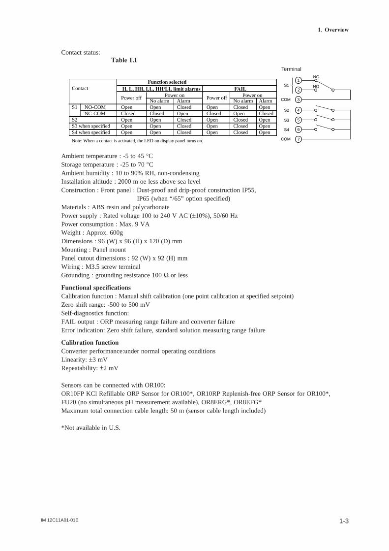
Contact status:Table 1.1
Function selectedContact H, L, HH, LL, HH/LL limit alarms FAIL
Power off Power on Power off Power onNo alarm Alarm No alarm Alarm
S1 NO-COM Open Open Closed Open Closed Open NC-COM Closed Closed Open Closed Open ClosedS2 Open Open Closed Open Closed OpenS3 when specified Open Open Closed Open Closed OpenS4 when specified Open Open Closed Open Closed Open
Note: When a contact is activated, the LED on display panel turns on.
4
5
6
7
1
2
3
S1
COM
S2
S3
S4
COM
NC
NO
Terminal
Ambient temperature : -5 to 45 °CStorage temperature : -25 to 70 °CAmbient humidity : 10 to 90% RH, non-condensingInstallation altitude : 2000 m oe less above sea levelConstruction : Front panel : Dust-proof and drip-proof construction IP55,
IP65 (when “/65” option specified)Materials : ABS resin and polycarbonatePower supply : Rated voltage 100 to 240 V AC (±10%), 50/60 HzPower consumption : Max. 9 VAWeight : Approx. 600gDimensions : 96 (W) x 96 (H) x 120 (D) mmMounting : Panel mountPanel cutout dimensions : 92 (W) x 92 (H) mmWiring : M3.5 screw terminalGrounding : grounding resistance 100 Ω or less
Functional specificationsCalibration function : Manual shift calibration (one point calibration at specified setpoint)Zero shift range: -500 to 500 mVSelf-diagnostics function:FAIL output : ORP measuring range failure and converter failureError indication: Zero shift failure, standard solution measuring range failure
Calibration functionConverter performance:under normal operating conditionsLinearity: ±3 mVRepeatability: ±2 mV
Sensors can be connected with OR100:OR10FP KCl Refillable ORP Sensor for OR100*, OR10RP Replenish-free ORP Sensor for OR100*,FU20 (no simultaneous pH measurement available), OR8ERG*, OR8EFG*Maximum total connection cable length: 50 m (sensor cable length included)
*Not available in U.S.

IM 12C11A01-01E1-4
IM 12C11A01-01E 2-1
2. Preparation for Operation
2. Preparation for Operation
2.1 UnpackingWhen the instrument arrives, unpack the package with care and check that the instrument has not beendamaged during transportation. In addition, please check that the specification matches the order, andrequired accessories are not missing. If damage is found retain the original packing materials (including theouter box) and immediately notify the carrier and the relevant Yokogawa sales office.
2.2 Choosing an Installation LocationThe EXA converter should be installed as close as possible to the sensor to avoid long cable runs betweensensor and converter, the cable length should not exceed 30 meters (100 feet.) Select an installation sitewhere:
• Mechanical vibrations and shocks are negligible
• No relay/power switches are in the direct environment
• Access is possible rear of the unit for wiring
• The transmitter is not mounted in direct sunlight or severe weather conditions
• Maintenance procedures are possible (avoiding corrosive environments)
The ambient temperature and humidity of the installation environment must be within the limits of theinstrument specifications.
IM 12C11A01-01E2-2
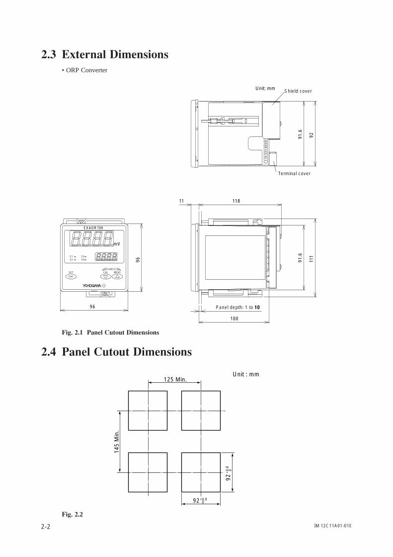
2.3 External Dimensions• ORP Converter
10
1-10
4151
-60
EXAOR100
mV
ENT
S1S2
S3S4
SET CAL MEASCANCEL
Unit: mm
11811
Panel depth: 1 to 1011
1
91.6
91.6
92100
96
96
Terminal cover
Shield cover
Fig. 2.1 Panel Cutout Dimensions
2.4 Panel Cutout Dimensions
125 Min.
145
Min
.
92+0.8 0
92+
0.8
0
Unit : mm
Fig. 2.2
IM 12C11A01-01E 2-3
2. Preparation for Operation
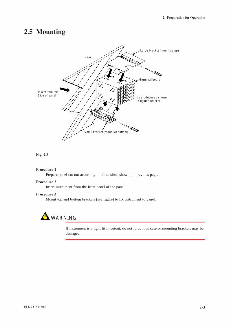
2.5 Mounting
Panel
Insert from thisSide of panel
Small bracket (mount at bottom)
Insert driver as shownto tighten bracket
Terminal board
Large brackct (mount at top)
Fig. 2.3
Procedure 1Prepare panel cut out according to dimensions shown on previous page.
Procedure 2Insert instrument from the front panel of the panel.
Procedure 3Mount top and bottom brackets (see figure) to fix instrument to panel.
WARNING
If instrument is a tight fit in cutout, do not force it as case or mounting brackets may bedamaged.

IM 12C11A01-01E2-4
IM 12C11A01-01E 3-1
3. Wiring
3. Wiring
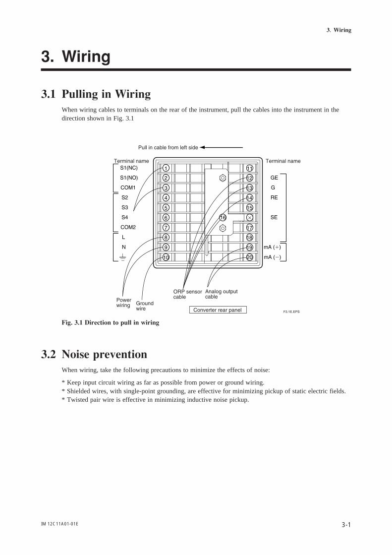
3.1 Pulling in WiringWhen wiring cables to terminals on the rear of the instrument, pull the cables into the instrument in thedirection shown in Fig. 3.1
Fig. 3.1 Direction to pull in wiring
3.2 Noise preventionWhen wiring, take the following precautions to minimize the effects of noise:
* Keep input circuit wiring as far as possible from power or ground wiring.* Shielded wires, with single-point grounding, are effective for minimizing pickup of static electric fields.* Twisted pair wire is effective in minimizing inductive noise pickup.
IM 12C11A01-01E3-2
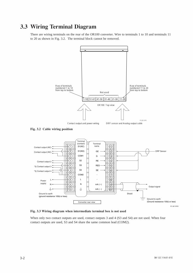
3.3 Wiring Terminal DiagramThere are wiring terminals on the rear of the OR100 converter. Wire to terminals 1 to 10 and terminals 11to 20 as shown in Fig. 3.2. The terminal block cannot be removed.
1-10 11-2051-61 41-50 31-40 21-30
F3.2E.EPS
Row of terminalsnumbered 1 to 10from top to bottom
Row of terminalsnumbered 11 to 20from top to bottom
OR100 Top view
Not used
Contact output and power wiring ORP sensor and Analog output cable
Fig. 3.2 Cable wiring position
Fig. 3.3 Wiring diagram when intermediate terminal box is not used
When only two contact outputs are used, contact outputs 3 and 4 (S3 and S4) are not used. When fourcontact outputs are used, S3 and S4 share the same common lead (COM2).
IM 12C11A01-01E 3-3
3. Wiring
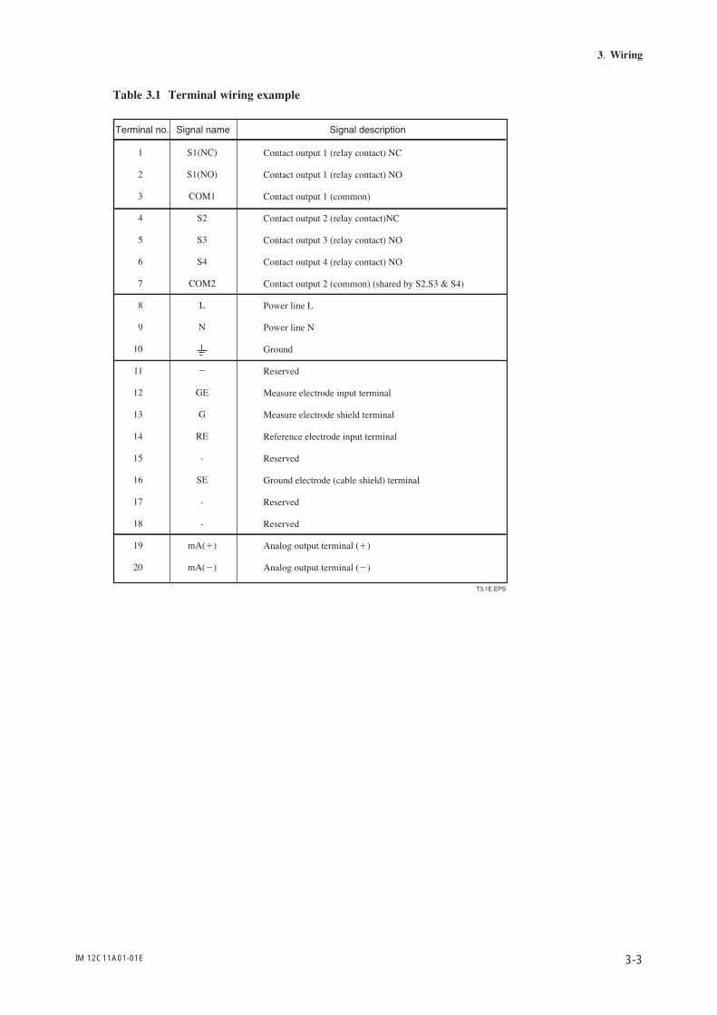
Table 3.1 Terminal wiring example
IM 12C11A01-01E3-4
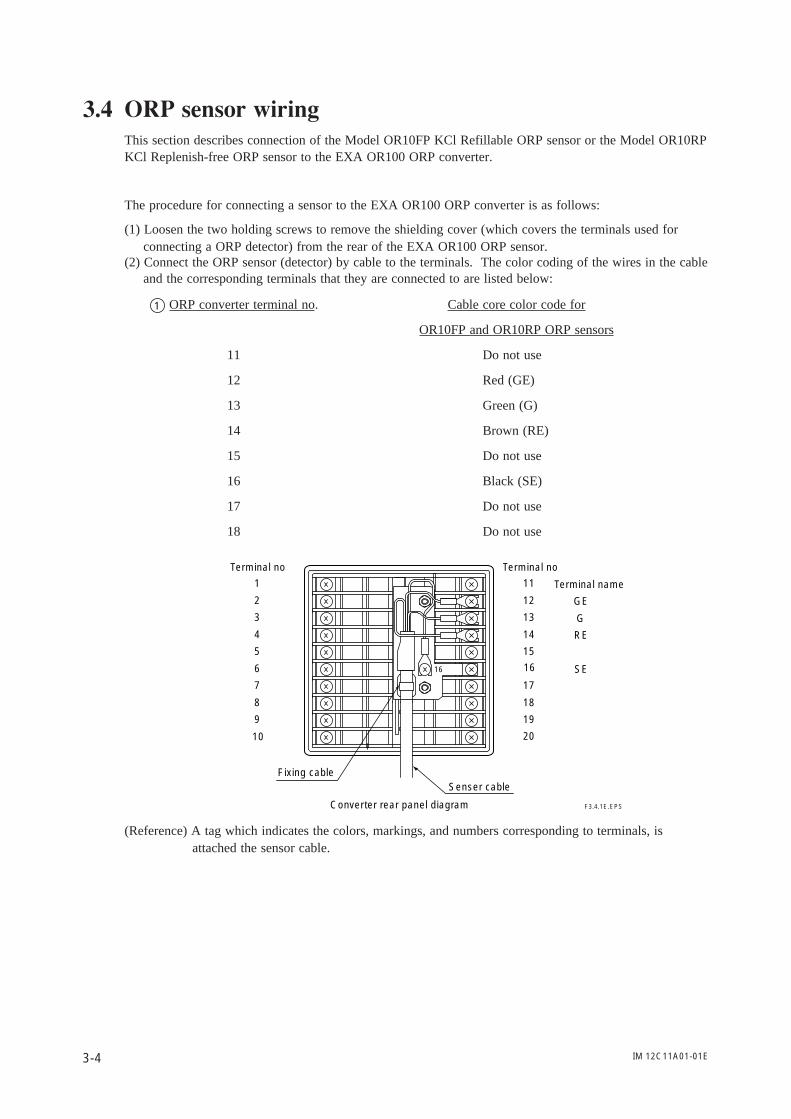
3.4 ORP sensor wiringThis section describes connection of the Model OR10FP KCl Refillable ORP sensor or the Model OR10RPKCl Replenish-free ORP sensor to the EXA OR100 ORP converter.
The procedure for connecting a sensor to the EXA OR100 ORP converter is as follows:
(1) Loosen the two holding screws to remove the shielding cover (which covers the terminals used forconnecting a ORP detector) from the rear of the EXA OR100 ORP sensor.
(2) Connect the ORP sensor (detector) by cable to the terminals. The color coding of the wires in the cableand the corresponding terminals that they are connected to are listed below:
1 ORP converter terminal no. Cable core color code for
OR10FP and OR10RP ORP sensors
11 Do not use
12 Red (GE)
13 Green (G)
14 Brown (RE)
15 Do not use
16 Black (SE)
17 Do not use
18 Do not use
20
19
18
17
16
15
14
13
12
11
10
9
8
7
6
5
4
3
2
1
Terminal no Terminal no
Terminal name
Fixing cableSenser cable
Converter rear panel diagram
GE
G
RE
SE16
F3.4.1E.EPS
(Reference) A tag which indicates the colors, markings, and numbers corresponding to terminals, is attached the sensor cable.
IM 12C11A01-01E 3-5
3. Wiring
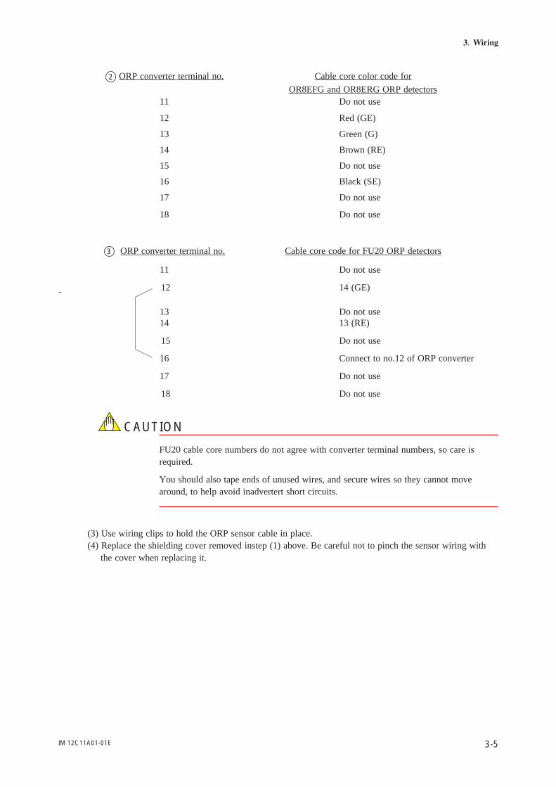
2 ORP converter terminal no. Cable core color code for
OR8EFG and OR8ERG ORP detectors11 Do not use
12 Red (GE)
13 Green (G)
14 Brown (RE)
15 Do not use
16 Black (SE)
17 Do not use
18 Do not use
3 ORP converter terminal no. Cable core code for FU20 ORP detectors
11 Do not use
12 14 (GE)-
13 Do not use14 13 (RE)
15 Do not use
16 Connect to no.12 of ORP converter
17 Do not use
18 Do not use
CAUTION
FU20 cable core numbers do not agree with converter terminal numbers, so care isrequired.
You should also tape ends of unused wires, and secure wires so they cannot movearound, to help avoid inadvertert short circuits.
(3) Use wiring clips to hold the ORP sensor cable in place.(4) Replace the shielding cover removed instep (1) above. Be careful not to pinch the sensor wiring with
the cover when replacing it.
IM 12C11A01-01E3-6
3.5 Wiring cable to intermediate terminal boxWhen the EXA OR100 ORP converter is separated by a distance from the ORP detector, use the EXAWTB100 or BA10 terminal box and EXA WF10 extension cable to connect them.
3.6 Output Signal Cable Wiring
To minimize the danger of shock, before connecting or disconnecting wires be sure to confirm that theORP converter power is OFF.
The output signal wiring from the OR100 converter connects to recorders or the like. Use two-coreshielded cable for this wiring.
(1) Connect connecting cable to the terminals. Be sure to use the recommended terminals and be sure thatthey are the correct size for the cable copper core diameter.
(2) As shown in Figures 3.2 and 3.3 of Section 3.3, ground to earth and ground connection at one pointonly.
3.7 Contact output wiring.
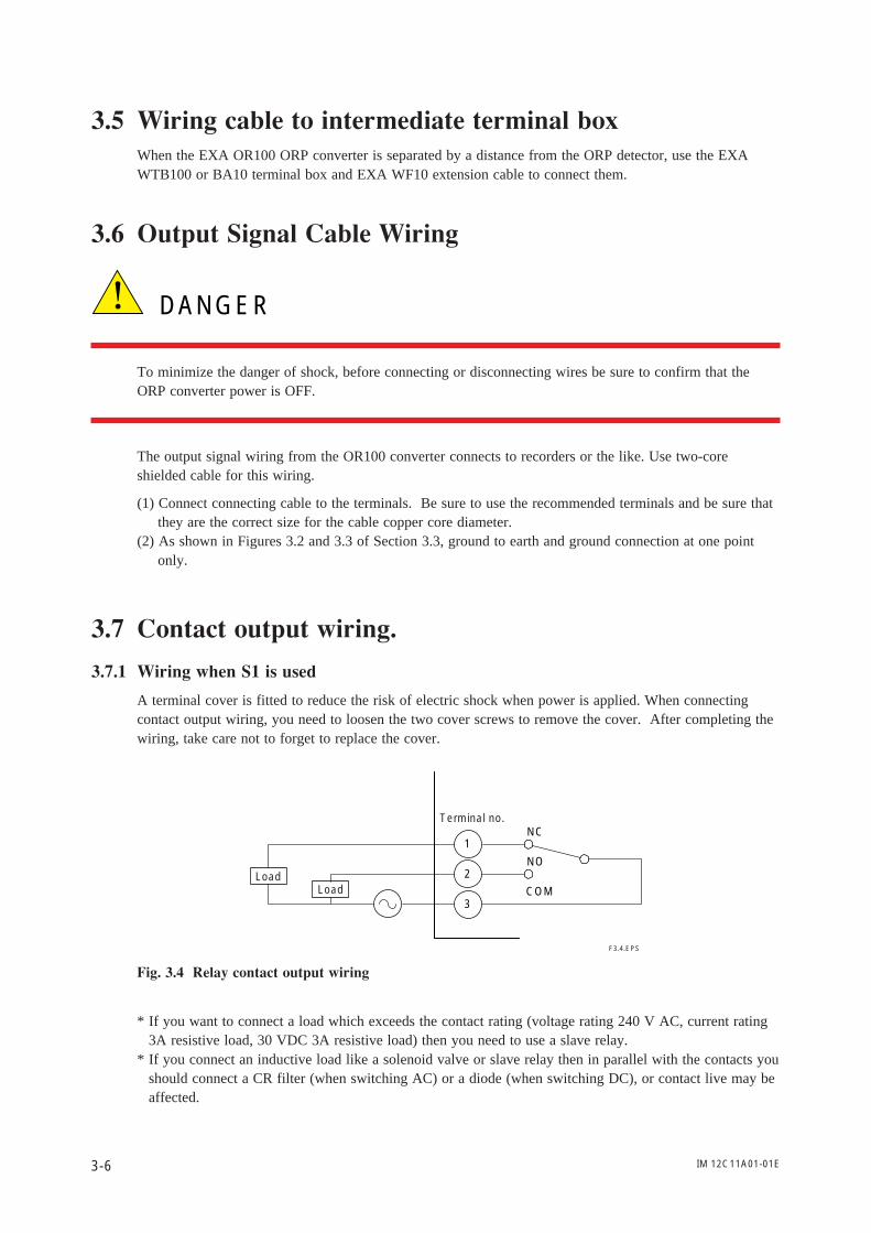
3.7.1 Wiring when S1 is used
A terminal cover is fitted to reduce the risk of electric shock when power is applied. When connectingcontact output wiring, you need to loosen the two cover screws to remove the cover. After completing thewiring, take care not to forget to replace the cover.
1
2
3
NC
NO
COM
F3.4.EPS
Load
Terminal no.
Load
Fig. 3.4 Relay contact output wiring
* If you want to connect a load which exceeds the contact rating (voltage rating 240 V AC, current rating3A resistive load, 30 VDC 3A resistive load) then you need to use a slave relay.
* If you connect an inductive load like a solenoid valve or slave relay then in parallel with the contacts youshould connect a CR filter (when switching AC) or a diode (when switching DC), or contact live may beaffected.
DANGER
IM 12C11A01-01E 3-7
3. Wiring
WARNING
* Be sure to disconnect power before removing the terminal cover. Since there is thedanger of shock, turn off power and confirm that terminals are not live before wiring.Under no circumstances should terminals be touched when power is applied.
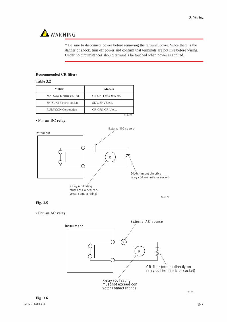
Recommended CR filters
Table 3.2
T3.2.EPS
CR UNIT 953, 955 etc.
SKV, SKVB etc.
CR-CFS, CR-U etc.
Maker Models
MATSUO Electric co.,Ltd
SHIZUKI Electric co.,Ltd
RUBYCON Corporation
• For an DC relay
R
F3.5.EPS
Instrument
External DC source
Relay (coil ratingmust not exceed con-verter contact rating)
Diode (mount directly onrelay coil terminals or socket)
Fig. 3.5
• For an AC relay
R
F3.6.EPS
InstrumentExternal AC source
Relay (coil ratingmust not exceed conveter contact rating)
CR filter (mount directly onrelay coil terminals or socket)
Fig. 3.6
IM 12C11A01-01E3-8
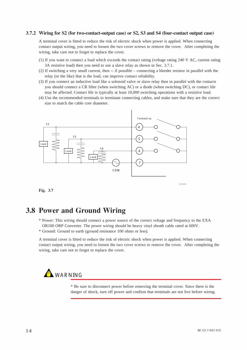
3.7.2 Wiring for S2 (for two-contact-output case) or S2, S3 and S4 (four-contact output case)
A terminal cover is fitted to reduce the risk of electric shock when power is applied. When connectingcontact output wiring, you need to loosen the two cover screws to remove the cover. After completing thewiring, take care not to forget to replace the cover.
(1) If you want to connect a load which exceeds the contact rating (voltage rating 240 V AC, current rating3A resistive load) then you need to use a slave relay as shown in Sec. 3.7.1.
(2) If switching a very small current, then -- if possible – connecting a bleeder resistor in parallel with therelay (or the like) that is the load, can improve contact reliability.
(3) If you connect an inductive load like a solenoid valve or slave relay then in parallel with the contactsyou should connect a CR filter (when switching AC) or a diode (when switching DC), or contact lifemay be affected. Contact life is typically at least 10,000 switching operations with a resistive load.
(4) Use the recommended terminals to terminate connecting cables, and make sure that they are the correctsize to match the cable core diameter.
5
6
7
4
COM
S4
S3
S2
F3.7.EPS
Load
Terminal no.
Load
Load
Fig. 3.7
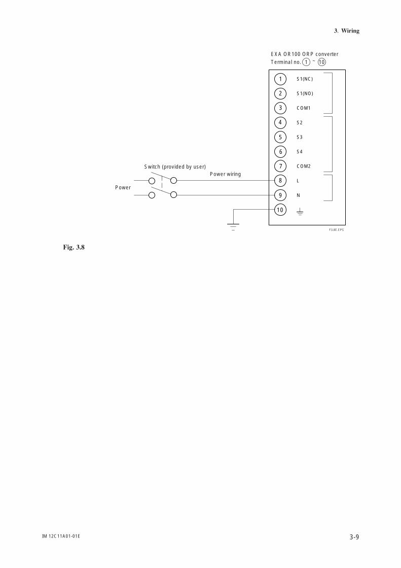
3.8 Power and Ground Wiring* Power: This wiring should connect a power source of the correct voltage and frequency to the EXA
OR100 ORP Converter. The power wiring should be heavy vinyl sheath cable rated at 600V.* Ground: Ground to earth (ground resistance 100 ohms or less).
A terminal cover is fitted to reduce the risk of electric shock when power is applied. When connectingcontact output wiring, you need to loosen the two cover screws to remove the cover. After completing thewiring, take care not to forget to replace the cover.
WARNING
* Be sure to disconnect power before removing the terminal cover. Since there is thedanger of shock, turn off power and confirm that terminals are not live before wiring.
IM 12C11A01-01E 3-9
3. Wiring
N
L
COM2
S4
S3
S2
COM1
S1(NO)
S1(NC)
10
9
8
7
6
5
4
3
2
1
F3.8E.EPS
EXA OR100 ORP converterTerminal no. 1 10~
Power
Switch (provided by user)Power wiring
Fig. 3.8

IM 12C11A01-01E3-10
IM 12C11A01-01E 4-1
4. Overview of Operation Panel
4. Overview of Operation Panel
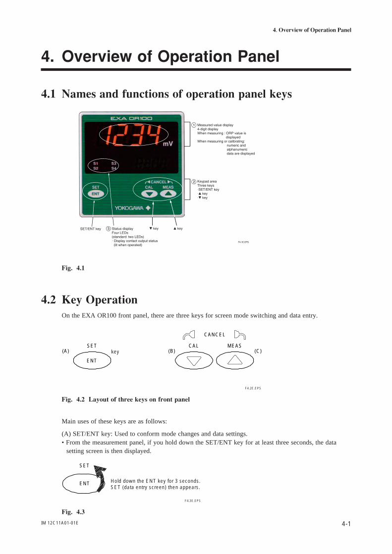
4.1 Names and functions of operation panel keys
Fig. 4.1
4.2 Key OperationOn the EXA OR100 front panel, there are three keys for screen mode switching and data entry.
ENT
SET CAL MEAS
CANCEL
(A) (B) (C)key
F4.2E.EPS
Fig. 4.2 Layout of three keys on front panel
Main uses of these keys are as follows:
(A) SET/ENT key: Used to conform mode changes and data settings.• From the measurement panel, if you hold down the SET/ENT key for at least three seconds, the data
setting screen is then displayed.
ENT
SET
F4.3E.EPS
Hold down the ENT key for 3 seconds. SET (data entry screen) then appears.
Fig. 4.3
IM 12C11A01-01E4-2
(B) key: Use to select different menu items or reduce data setting value.• Holding down this key for at least three seconds switches to the calibration screen.
Fig. 4.4
(C) key: Use to select different menu item or increase data setting value.• Holding down this key for at least three seconds from calibration or data setting top screen switches tothe measurement screen.
Fig. 4.5
(B) and (C) Pressing and keys simultaneously cancel operations.
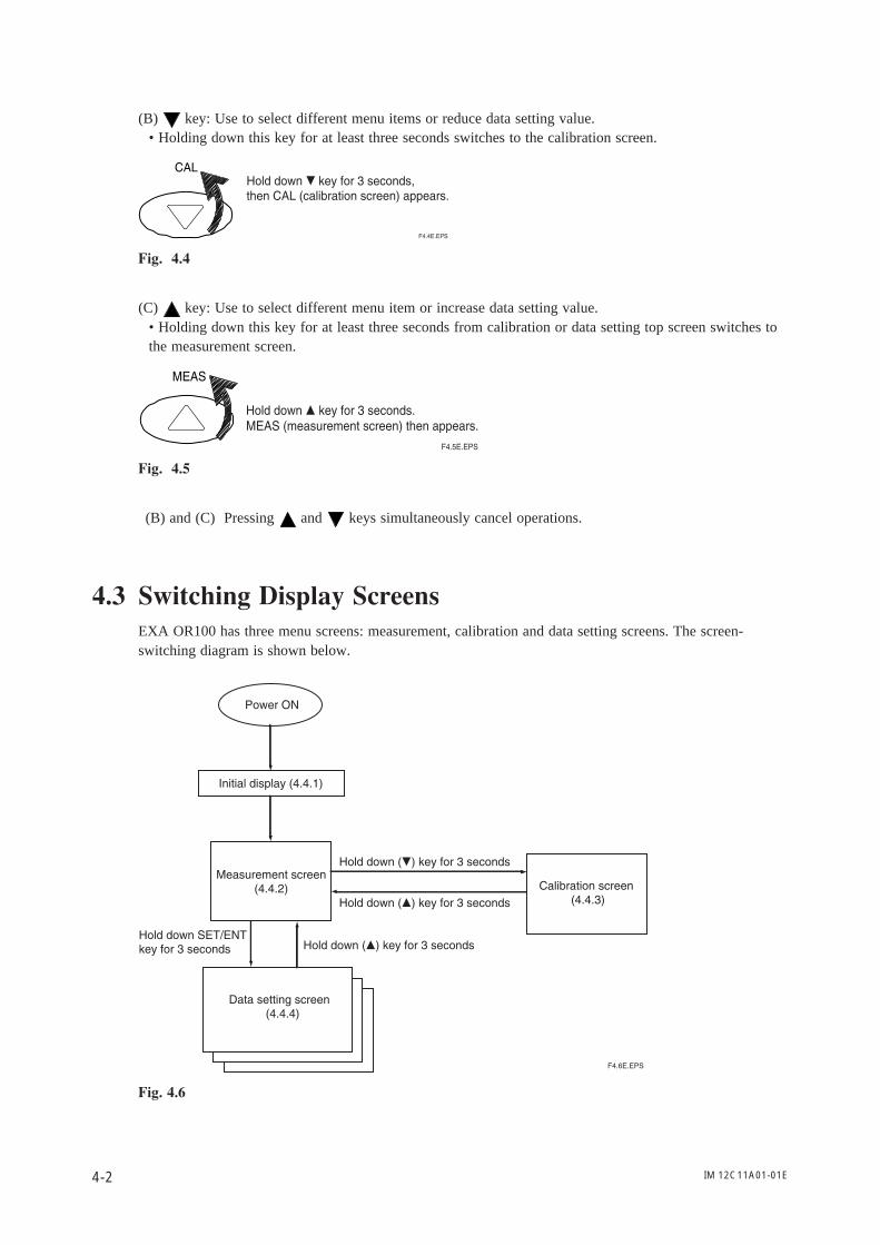
4.3 Switching Display ScreensEXA OR100 has three menu screens: measurement, calibration and data setting screens. The screen-switching diagram is shown below.
Fig. 4.6
IM 12C11A01-01E 4-3
4. Overview of Operation Panel
4.4 Display Screen Examples
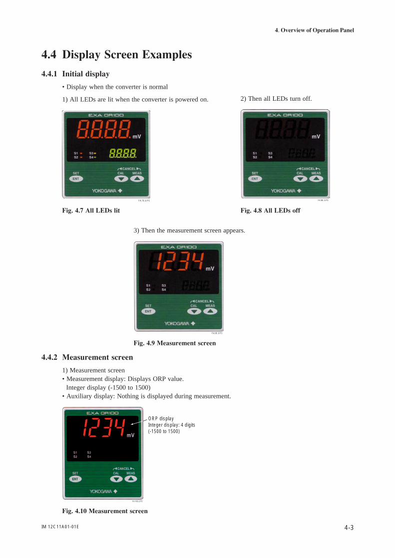
4.4.1 Initial display
• Display when the converter is normal
1) All LEDs are lit when the converter is powered on.
F4.7E.EPS
Fig. 4.7 All LEDs lit
2) Then all LEDs turn off.
F4.8E.EPS
Fig. 4.8 All LEDs off
3) Then the measurement screen appears.
F4.9E.EPS
Fig. 4.9 Measurement screen
4.4.2 Measurement screen
1) Measurement screen• Measurement display: Displays ORP value. Integer display (-1500 to 1500)• Auxiliary display: Nothing is displayed during measurement.
F4.10E.EPS
ORP displayInteger display: 4 digits (-1500 to 1500)
Fig. 4.10 Measurement screen
IM 12C11A01-01E4-4
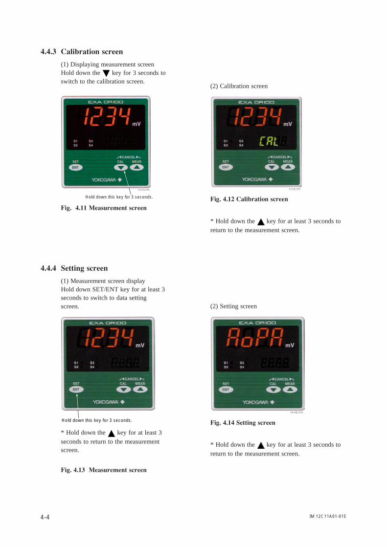
4.4.3 Calibration screen
(1) Displaying measurement screenHold down the key for 3 seconds toswitch to the calibration screen.
F4.11E.EPS
Hold down this key for 3 seconds.
Fig. 4.11 Measurement screen
(2) Calibration screen
F4.12E.EPS
Fig. 4.12 Calibration screen
* Hold down the key for at least 3 seconds toreturn to the measurement screen.
4.4.4 Setting screen
(1) Measurement screen displayHold down SET/ENT key for at least 3seconds to switch to data settingscreen.
Hold down this key for 3 seconds.
* Hold down the key for at least 3seconds to return to the measurementscreen.
Fig. 4.13 Measurement screen
(2) Setting screen
F4.14E.EPS
Fig. 4.14 Setting screen
* Hold down the key for at least 3 seconds toreturn to the measurement screen.
IM 12C11A01-01E 5-1
5. Operation
5. Operation
5.1 Start up
5.1.1 Checking wiring
Check that all wiring connections have been properly completed (see Section 3.3).
5.1.2 Start up ORP converter
Apply power (specified on the instrument nameplate) to the OR100 Panel Mounted ORP Converter.
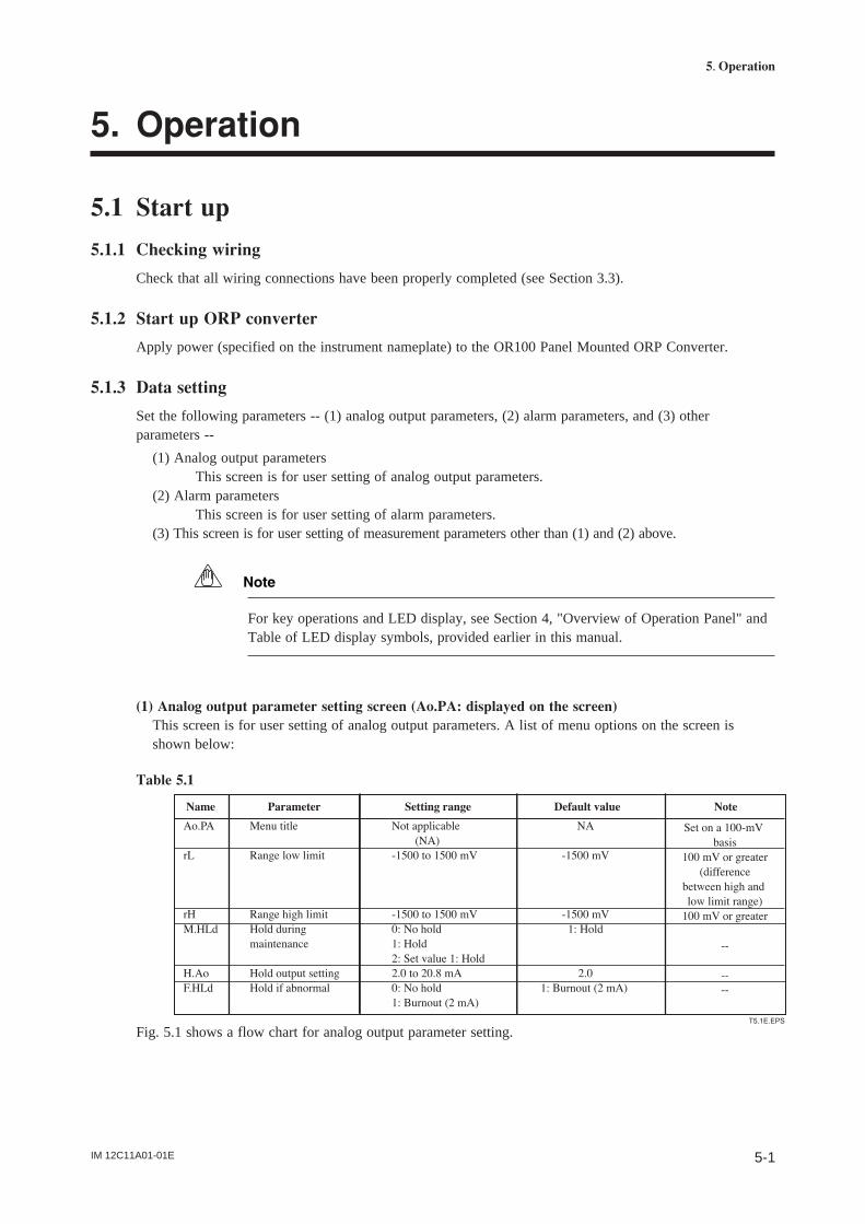
5.1.3 Data setting
Set the following parameters -- (1) analog output parameters, (2) alarm parameters, and (3) otherparameters --
(1) Analog output parametersThis screen is for user setting of analog output parameters.
(2) Alarm parametersThis screen is for user setting of alarm parameters.
(3) This screen is for user setting of measurement parameters other than (1) and (2) above.
Note
For key operations and LED display, see Section 4, "Overview of Operation Panel" andTable of LED display symbols, provided earlier in this manual.
(1) Analog output parameter setting screen (Ao.PA: displayed on the screen)This screen is for user setting of analog output parameters. A list of menu options on the screen isshown below:
Table 5.1
Fig. 5.1 shows a flow chart for analog output parameter setting.
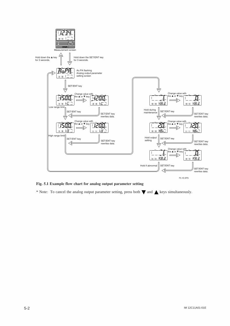
IM 12C11A01-01E5-2
Fig. 5.1 Example flow chart for analog output parameter setting
* Note: To cancel the analog output parameter setting, press both and keys simultaneously.
IM 12C11A01-01E 5-3
5. Operation
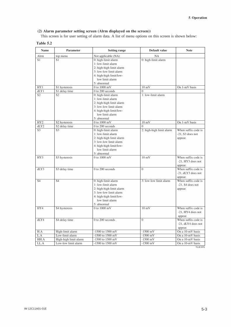
(2) Alarm parameter setting screen (Alrm displayed on the screen))This screen is for user setting of alarm data. A list of menu options on this screen is shown below:
Table 5.2
IM 12C11A01-01E5-4
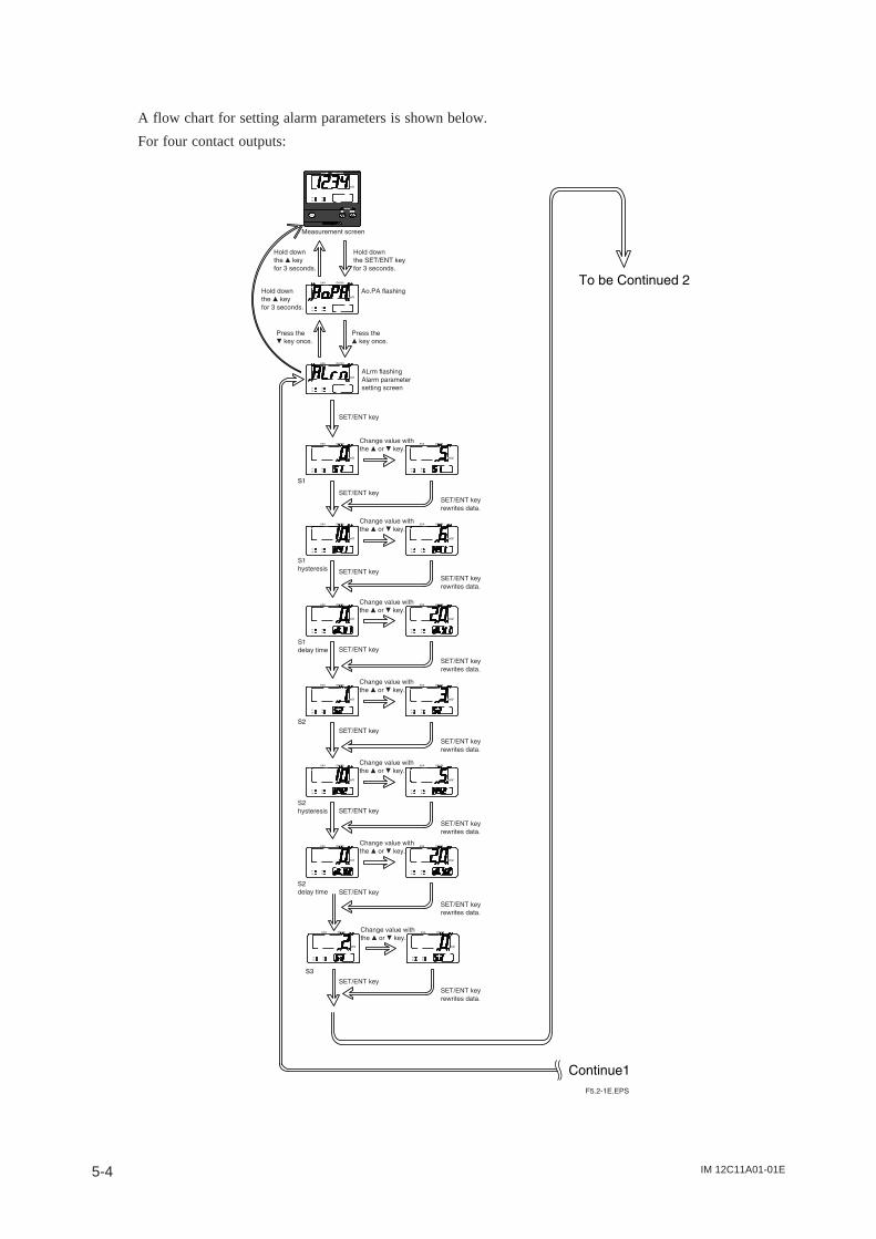
A flow chart for setting alarm parameters is shown below.
For four contact outputs:
IM 12C11A01-01E 5-5
5. Operation
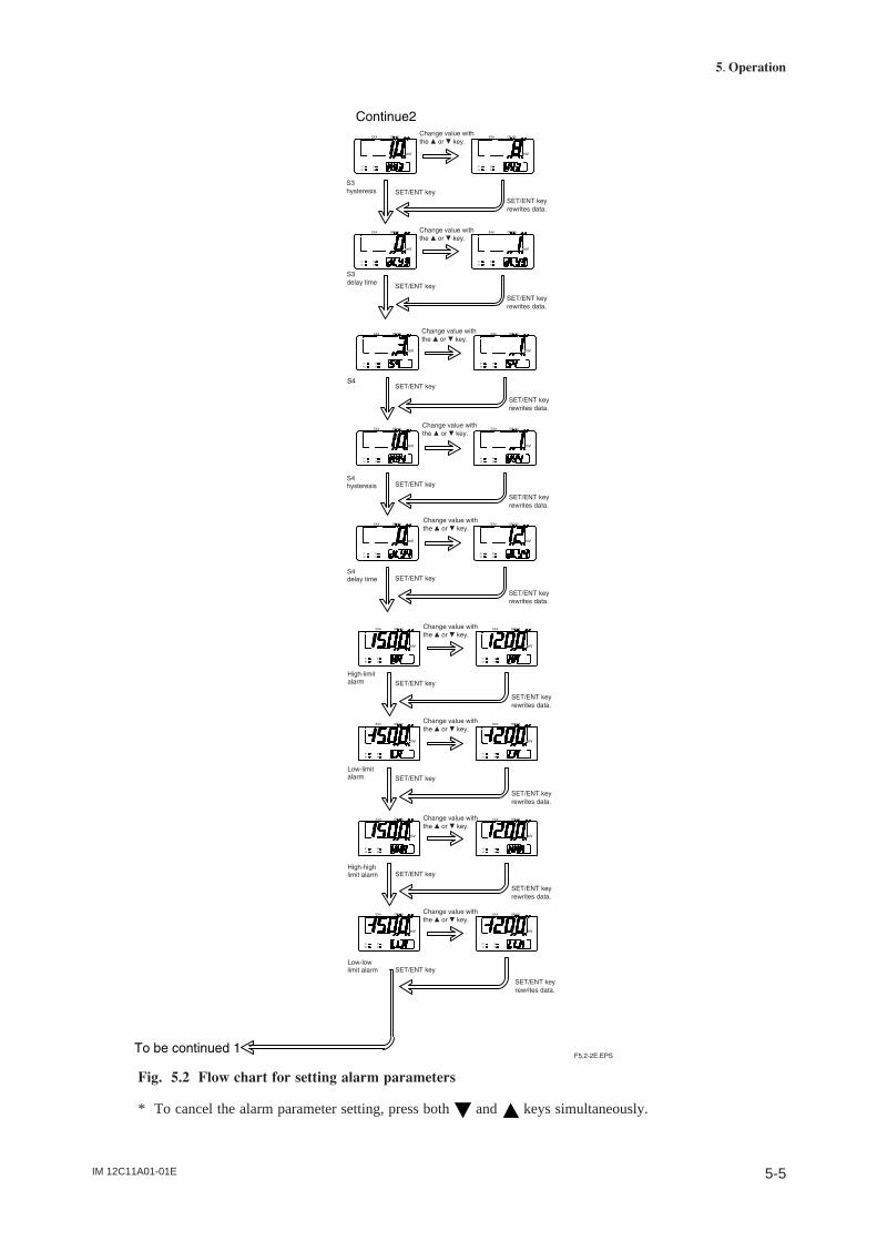
Fig. 5.2 Flow chart for setting alarm parameters
* To cancel the alarm parameter setting, press both and keys simultaneously.
IM 12C11A01-01E5-6
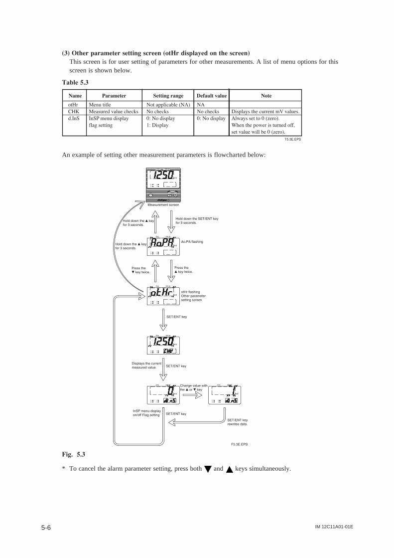
(3) Other parameter setting screen (otHr displayed on the screen)This screen is for user setting of parameters for other measurements. A list of menu options for thisscreen is shown below.
Table 5.3
An example of setting other measurement parameters is flowcharted below:
Fig. 5.3
* To cancel the alarm parameter setting, press both and keys simultaneously.
IM 12C11A01-01E 6-1
6. Sensor Check and Calibration Procedures
6. Sensor Check and CalibrationProcedures
Dirt attached to the liquid junction or sensitive parts (platinum electrodes) may have an adverse effect onelectromotive force and response characteristics, so ORP sensors require periodic cleaning for goodoperating conditions. ORP sensors should be checked and calibrated if the following conditions are met.
(1) Sensor checks• If a new ORP sensor is used or the existing sensor has been unused for an extended period of time.• When an ORP sensor sensitive part (platinum electrode) or a liquid junction is cleaned.(2) Calibration• If sensor electromotive force is outside the allowable ranges.• If the measured value by the ORP sensor is adjusted to the measured value by other sensors.
6.1 Overview of Sensor Checks and Calibration
6.1.1 Sensor checks
A standard solution with known Oxidation-Reduction Potential should be measured. Check that themeasured value is within the allowable range. The sensor shall be checked in the measurement mode.
6.1.2 Calibration (manual calibration)
Use a solution with ORP values to calibrate that the ORP sensor for OR100 indicates those values. Duringmanual calibration, the measured value of the ORP sensor for OR100 is adjusted to the known value. Thiscalibration procedure is also used where sensor check results are somewhat outside the allowable ranges.For more details, see Section 6.3, later in this manual.
6.1.3 Sensor check solution
Use a Quinhydrone solution or iron solution for sensor checking.
6.2 Checking Sensors
6.2.1 Preliminary
(1) Rinse the ORP sensor sensitive part and any grime with clean water.(2) Preparation for sensor check solution.
6.2.2 Checking sensors
Display the CHK on the other parameter setting screen to check the ORP sensor.
Note: This will place the 4-20mA in hold.
(1) Immerse the ORP sensor in the checking solution.(2) Read a displayed value.Note: Allow a sensor value to be stabilized, and then read a displayed value.Note: If the displayed value is outside the allowable range, conduct a manual calibration by referring toSection 6.3, later in this manual.
IM 12C11A01-01E6-2
6.3 Manual Calibration
6.3.1 Preliminary
Rinse the ORP sensor sensitive part and any grime with clean water.
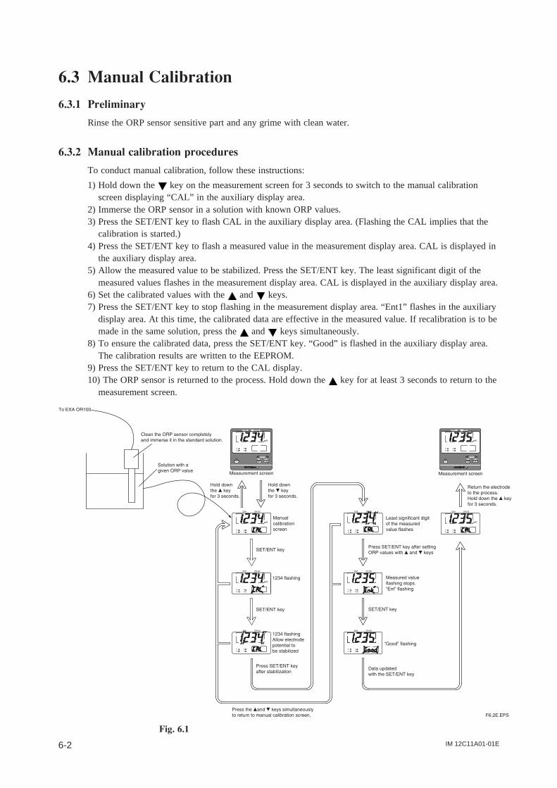
6.3.2 Manual calibration procedures
To conduct manual calibration, follow these instructions:
1) Hold down the key on the measurement screen for 3 seconds to switch to the manual calibrationscreen displaying “CAL” in the auxiliary display area.
2) Immerse the ORP sensor in a solution with known ORP values.3) Press the SET/ENT key to flash CAL in the auxiliary display area. (Flashing the CAL implies that the
calibration is started.)4) Press the SET/ENT key to flash a measured value in the measurement display area. CAL is displayed in
the auxiliary display area.5) Allow the measured value to be stabilized. Press the SET/ENT key. The least significant digit of the
measured values flashes in the measurement display area. CAL is displayed in the auxiliary display area.6) Set the calibrated values with the and keys.7) Press the SET/ENT key to stop flashing in the measurement display area. “Ent1” flashes in the auxiliary
display area. At this time, the calibrated data are effective in the measured value. If recalibration is to bemade in the same solution, press the and keys simultaneously.
8) To ensure the calibrated data, press the SET/ENT key. “Good” is flashed in the auxiliary display area.The calibration results are written to the EEPROM.
9) Press the SET/ENT key to return to the CAL display.10) The ORP sensor is returned to the process. Hold down the key for at least 3 seconds to return to the
measurement screen.
Fig. 6.1
IM 12C11A01-01E 6-3
6. Sensor Check and Calibration Procedures
6.4 Canceling CalibrationTo cancel the calibration:
1) Press the and keys simultaneously several times until the first calibration screen (A.CAL or CALdisplay in the auxiliary display area) appears. At this time, the calibration results are not updated.
2) Restore the sensor to the process and hold down the key for at least 3 seconds to return to themeasurement screen.
6.5 If an Error Occurs during CalibrationIf the asymmetry potential is outside the range -500 mV to 500 mV, a calibration error will result.Measured values are displayed in the measured value display area and an error code flashes in the auxiliarydisplay area. No calibrated results are updated.
(For more details on error codes, see Tables 8.1 and 8.2, later in this manual.)
CAUTION
Key entries are accepted only when the and keys are pressed simultaneously onboth the auto-calibration screen and manual calibration screen.
6.5.1 Recovering from an Error
To make a recalibration:
1) Press the and keys simultaneously several times until the first calibration screen appears.2) Press the SET/ENT key. Then you can perform calibration work again.
6.5.2 Quitting calibration screen
1) Press the and key simultaneously to return to the first calibration screen.2) Hold down the key for at least 3 seconds to return to the measurement screen.

IM 12C11A01-01E6-4
IM 12C11A01-01E 7-1
7. Maintenance and Cleaning
7. Maintenance and Cleaning
7.1 Periodic Maintenance
7.1.1 Sensor cleaning
When the platinum electrode or liquid junction of the ORP sensor becomes dirty, the measured value maybe unstable or drift, and response may become very slow. To avoid this, clean the sensor periodically.
7.1.2 Checking the KCl solution for ORP sensor
If KCl refillable ORP sensors are used, replenish KCl solutions periodically.
CAUTION
Refer to applicable ORP sensor instruction manuals for replenishing KCl solutions.
7.2 Preventive Maintenance
7.2.1 ORP converter terminal isolation
ORP sensor input terminals shall be isolated with each other with a high resistance. Check the sensorterminals once or twice a year to confirm that they are not dirty, and have not been affected bycondensation.
7.2.2 Checking ORP sensor displays
Use soft cloth or tissue paper to clean off any dirt on the displays of the EXA OR100 ORP converter. Ifrequired, you may use neutral detergent to remove dirt, but avoid using organic solvents.

IM 12C11A01-01E7-2
IM 12C11A01-01E 8-1
8. Troubleshooting
8. Troubleshooting
8.1 Unexpected Value Displayed (Pinpointing the Causes ofProblems with Converter or Sensor)
A. If unexpected values are displayedStep 1:
• Check the KCl level in the sensor.
Step 2:
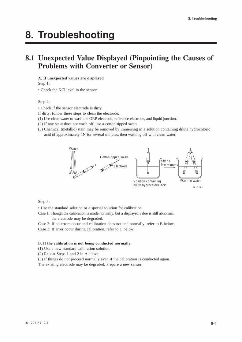
• Check if the sensor electrode is dirty.If dirty, follow these steps to clean the electrode:(1) Use clean water to wash the ORP electrode, reference electrode, and liquid junction.(2) If any stain does not wash off, use a cotton-tipped swab.(3) Chemical (metallic) stain may be removed by immersing in a solution containing dilute hydrochloric acid of approximately 1N for several minutes, then washing off with clean water.
F8.1E.EPS
Water
Cotton-tipped swab
Electrode
Solution containing dilute hydrochloric acid
After a few minutes
Wash in water
Step 3:
• Use the standard solution or a special solution for calibration.Case 1: Though the calibration is made normally, but a displayed value is still abnormal, the electrode may be degraded.Case 2: If no errors occur and calibration does not end normally, refer to B below.Case 3: If error occur during calibration, refer to C below.
B. If the calibration is not being conducted normally.(1) Use a new standard calibration solution.(2) Repeat Steps 1 and 2 in A above.(3) If things do not proceed normally even if the calibration is conducted again.The existing electrode may be degraded. Prepare a new sensor.

IM 12C11A01-01E8-2
If an error occurs during calibration:Follow the flowchart instructions below. Refer to Section 8.2, “Displaying Errors,” later in this manual.
If error C-01 occurs during the standard calibration
YES
YES
YES
YES
NO
NO
NO
NO
F8.2E.EPS
Enter a correct ORP value.Is the entered ORP value correct?
Clean electrode.Is the electrode dirty?
Make the liquid junction wet.Has the liquid junction dried out?
(See **)
Refill electrode with KCl. Has KCl in electrode run out?
(See *)
Electrode degraded.Replace electrode.If error C-01 occurs,
use the standard solution within its normal temperature range
** Immerse the liquid junction in the ORP standard solution for 12 hours.
C. If an error occurs during measurement:Follow the procedures shown in the flowchart below.
Refer to Section 8.2, Displaying Errors," later in this manual.
If error E-01 occurs during measurement
YES
YES
NO
NO
F8.3E.EPS
Clean the electrode.Is the electrode dirty?
Correct cable connections.
Wrong cable connections?
Electrode degraded.Replace the sensor.
IM 12C11A01-01E 8-3
8. Troubleshooting
D. If replacing sensor does not revert to normal:• The converter may be defective.
E. Error E-04 occurs.• The converter may be defective.
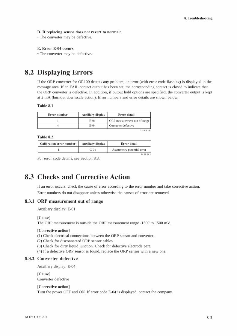
8.2 Displaying ErrorsIf the ORP converter for OR100 detects any problem, an error (with error code flashing) is displayed in themessage area. If an FAIL contact output has been set, the corresponding contact is closed to indicate thatthe ORP converter is defective. In addition, if output hold options are specified, the converter output is keptat 2 mA (burnout downscale action). Error numbers and error details are shown below.
Table 8.1
1 E-01 ORP measurement out of range
4 E-04 Converter defective
T8.1E.EPS
Error number Auxiliary display Error detail
Table 8.2
T8.2E.EPS
Calibration error number Auxiliary display Error detail
1 C-01 Asymmetry potential error
For error code details, see Section 8.3.
8.3 Checks and Corrective ActionIf an error occurs, check the cause of error according to the error number and take corrective action.
Error numbers do not disappear unless otherwise the causes of error are removed.
8.3.1 ORP measurement out of range
Auxiliary display: E-01
[Cause]The ORP measurement is outside the ORP measurement range -1500 to 1500 mV.
[Corrective action](1) Check electrical connections between the ORP sensor and converter.(2) Check for disconnected ORP sensor cables.(3) Check for dirty liquid junction. Check for defective electrode part.(4) If a defective ORP sensor is found, replace the ORP sensor with a new one.
8.3.2 Converter defective
Auxiliary display: E-04
[Cause]Converter defective
[Corrective action]Turn the power OFF and ON. If error code E-04 is displayed, contact the company.

IM 12C11A01-01E8-4
8.3.3 Calibration asymmetry potential error
Auxiliary display: C-01
[Cause]If asymmetry potential is outside the range -500 mV to 500 mV, a calibration error occurs.
[Corrective action](1) The entered ORP values are not correct.(2) Check for dirty ORP sensor or liquid junction. If it is dirty, clean the electrode.(3) The ORP sensor may be degraded.(4) If the ORP sensor is defective, replace the ORP sensor.

Revision Record
Manual Title : Model OR100 Panel Mount ORP Converter
Manual Number : IM 12C11A01-01E
Edition Date Remark (s)
1st May. 2003 Newly published
2nd March 2004 US modifications