user’s manual - channel.invengo.coms manual for... · shock resistance: gb/t 2423.10-2008/iec...
TRANSCRIPT

User’s ManualXC2903 Handheld Reader
Invengo Information Technology Co., Ltd.

Foreword
XC2903 Handheld Reader
This manual provides information on product application, maintenance, repair and other features for users and maintenance personnel of the products.
All introduction and descriptions written in this manual, in respect of the product’s features, functions and other relevant information, are the latest. All information provided is accurate during the time of printing. The company retains all rights to make any correction or amendment to this manual without prior notice and shall bear no responsibility for these actions.
Some of the product functions may vary due to different configuration upon special requests from client.

Main content
Product overview
Performance parameters
Size and weight
Structural features and working principals
Common functions and settings
Product accessories
Product certification32 – Procurement code
Routine maintenance and FAQs
Transport and storage
Packaging and inspection
After-sales

Safety Instructions
Warning sign
If operate improperly, it may result in damage to your equipment(s).
Attention
If ignored, it may result in unsuccessful operationIf ignored, it may cause undesirable effect

Content
1. Product overview.........................................................................11.1 Product introduction ......................................................................................... 1
1.2 Main usage and applicable range .................................................................... 2
1.3 Operating conditions ........................................................................................ 2
1.4 Safety and protective measures ...................................................................... 2
2. Performance parameters ............................................................32.1 Main functions ................................................................................................... 3
2.2 Technical parameter .......................................................................................... 3
3. Size and weight............................................................................73.1 Weight ................................................................................................................. 7
4. Structural features and working principals ..............................84.1 Overall structure and working principals........................................................ 8
4.1.1 Appearance description .......................................................................................... 84.1.2 LED indicator ......................................................................................................... 94.1.3 Keyboard .............................................................................................................. 104.1.4 Battery installation and dismount......................................................................... 114.1.5 Shutdown/Standby/Restart ................................................................................... 114.1.6 Application management ...................................................................................... 12
5. Commonly use functions and settings ...................................135.1 Screen calibration ........................................................................................... 13
5.2 Battery level, charging status inquiries and backlight adjustment ............ 13
5.3 Volume and sounds ......................................................................................... 15
5.4 USB driver installation and data synchronization (with PC) ....................... 15

5.5 Installation of Display Software ..................................................................... 16
5.5.1 Software installation and initialization................................................................. 16
5.6 Camera functions ............................................................................................ 17
5.7 Instructions on Wi-Fi module ........................................................................ 18
5.8 Instructions on UHF-RFID module ................................................................. 21
5.8.1 Module introduction ............................................................................................. 215.8.2 UHF-RFID module technical parameters ............................................................ 215.8.3 Software operation ............................................................................................... 22
5.9 Description on API interface program ........................................................... 23
5.9.1 Barcode collection display software .................................................................... 23
5.10 GPRS Module Application Overview (Optional module) ........................... 25
5.10.1 GPRS module technical parameters ................................................................... 255.10.2 GRPS module application .................................................................................. 25
6. Accessories description ...........................................................276.1 Multifunctional cradle (Optional product) ..................................................... 27
7. Product Certification .................................................................29
8. Procurement Code ....................................................................30
9. Routine maintenance, FAQs and troubleshooting .................319.1 Routine maintenance ...................................................................................... 31
9.2 FAQs and troubleshooting ............................................................................. 32
9.3 RF Communication optimization ................................................................... 34
9.3.1 Signal Interference ............................................................................................... 349.3.2 Signal attenuation/reflection................................................................................. 34
10. Transportation and storage ....................................................3610.1 Transport requirements ................................................................................ 36
10.2 Storage requirements ................................................................................... 36

11. Packaging and Unpacking ......................................................3711.1 Packaging ...................................................................................................... 37
11.2 Unpacking ...................................................................................................... 37
12. After-sales ................................................................................3812.1 After-sales service ......................................................................................... 38
12.2 Other matters ................................................................................................. 38

User ManualXC2903 Handheld Reader
1
1. Product overview
1. Product overview
1.1 Product introduction
Thank you for using XC2903 Handheld reader. XC2903 is our company latest model of handheld reader. It is a smart multipurpose UHF-RFID tag reader equipped with fast processing speed, great portability and high functionality.
Figure 1 XC2903 Handheld Reader
XC2903 has multiple functional modules for different types of applications (as described below in table 1):
Table 1 – XC2903 handheld reader functional modules
Configuration type Module nameStandard configuration Wi-Fi module/UHF-RFID moduleOptional configuration GPRS module/PSAM card module/camera/1D-2D barcode
reader module/multifunctional cradle
If the user wishes to add on additional configuration modules, please hand in your initial request and allow our professional staff to run installation and testing prior to delivery.

User ManualXC2903 Handheld Reader
2
1.2 Main usage and applicable range
XC2903 has rich features and can be used widely in various fields, such as food safety industry, warehouse logistics management, retail logistics center management, transportation management and automated production line management, etc.
1.3 Operating conditions
XC2903 needs the following operating conditions:Temperature range: -10oC – 60oCStorage temperature: -20oC - +70oCOperating humidity: 5% RH – 95% RH, non-condensingStorage humidity: 5% RH – 95% RH, non-condensing
1.4 Safety and protective measures
Please refer to the following important statement before use!
Any radio transmitting equipment, including this equipment, may cause interference with medical equipment that is not properly protected. Should any problem occur, in respect of the aforementioned, please consult your medical equipment manufacturer. The operation of this equipment may also cause interference with other electronic devices.
1. Product overview

User ManualXC2903 Handheld Reader
3
2. Performance parameters
2.1 Main functions
● Support mainstream 1D, 2D barcode reading
● Support Wi-Fi, GPRS wireless data transmission
● Support EPC C1G2 (ISO 18000-6C)/ISO 18000-6B
● Support PSAM card reading operation
● Simple user interface, users are able to learn to operate the device easily
● Support touch screen, support Chinese character data input
● Support large capacity TF card (maximum 32G)
● Provide client with .Net SDK and standard environment for secondary development
2.2 Technical parameter
Table 2-1 Function parameter
Processor 806MHz PXA320 processor
Memory System internal memory: 256MBFlash memory: 256MB
Operating system Windows CE 6.0
Power source Lithium battery:Standard Removable 3800mAh/3.7 V rechargeable lithium battery Optional Removable 5700mAh/3.7V rechargeable lithium battery
Adaptor:AC input: 100V - 240V/50Hz - 60HzDC output: DC5V/4A
Working time: Standby - Not less than 30 days; operating duration - not less than 8hrs (30s reading interval) Work Status: Real-time monitoring of battery voltage, remaining battery and charging status
2. Performance parameters

User ManualXC2903 Handheld Reader
4
Software development environment
HTML, XMLSoftware device development kit Net Compact Framework 2.0 / 3.5 C#Standard Windows CE application protocol interface (APIs)SQL CE database engine
Application software
Microsoft ActiveSyncRFID handheld generic demo softwareBarcode demo softwareSerial debugging tool
UHF-RFID module
Supported protocols: EPC C1G2 (ISO 18000-6C)/ISO 18000-6BOperating frequency: 920MHz—925MHz/840MHz—845MHz/902MHz—928MHz OptionalOutput power: 9—27dBm, stepping 3dBmDebug mode: PR-ASKReading distance: (XCTF-8030B-C07 type tag)Tag reading: 0—5.0m,tag writing: 0--1.5mMaximum tag capacity:• Maximum 62 bytes for EPC• Maximum 16 bytes for TID• Maximum 8K bytes for user data
Wi-Fi module Supported protocols: IEEE802.11b/g (2.4G band)Communication speed:• 802.11b, 1Mbps, 2Mbps, 5.5Mbps, 11Mbps• 802.11g, 6Mbps, 9Mbps, 12Mbps, 18Mbps, 24Mbps, 36Mbps,
48Mbps, 54MbpsCommunication security:• WEP 64-bit, WEP 128-bit• WPA/WPA2• AES-CCMP
Transmission distance:• Indoor 20m• Outdoor 50m
PSAM card module (Optional)
Support ISO7816 Standard T=0/T=1 format 3.3V operating voltage9600bps communication rateSupport transparent transmission mode
2. Performance parameters

User ManualXC2903 Handheld Reader
5
Camera module (Optional)
3 mega pixelsJPEG format (default)Only support static photography
GSM module (Optional)
Working frequency: EGSM900, GSM1800, GSM850, GSM1900Supported protocols: TCP, UDP, HTTP, FTP, SMTP, POP3Communication security:• Support all GSM/GPRS authentication, encryption algorithm• Support frequency hopping technology
Barcode engine (Optional)
To choose between Honeywell 5100SR barcode engine and Motorola SE4500 barcode engine5100SR barcode scanning engine focuses on 2D barcode; SE4500 barcode scanning engine focuses on 1D barcode;SE4500 is recommended.Resolution: 752 X 480 pixelsScanning angle: ±40°Scan mode: Trigger mode, interrupt modeSupport code system:• 1D code: Code 39, Code 128, Codabar, UPC, EAN, ITF 25, RSS,
Code 93, Code block• 2D code: PDF 417, MicroPDF417, Maxi Code, Data matrix, QR
Code, Aztec, Aztec Mesa, Code 49, UCC Composite
User interface LCD Screen:• Bright white backlight with manually adjustable backlight
brightness• 240×320 resolution, QVGA TFT colour display
Touch screen: • 4-wire resistive touch screen• Equipped with a stylus
Keyboard:• Multifunctional multiplexing keys• 4 custom keys• Key life of 300,000 times or more• Blue LED backlit keyboard
Speakers and light:• Built-in 0.5W mono speaker• Network indicator (blue), power status indicator (red)
2. Performance parameters

User ManualXC2903 Handheld Reader
6
Internal expansion Support Micro SD / TF card expansion up to 32GB Support Integrated Circuits (IC) card Support contact PSAM card
External ports RS-232 serial port USB1.1device port 5V DC power input port
Working environment
Temperature range: -10oC – +60oCStorage temperature: -20oC - +70oCOperating humidity: 5% RH – 95% RH, non-condensingStorage humidity: 5% RH – 95% RH, non-condensingProtective level: IP65Anti-drop capability: 1.2m Shock resistance: GB/T 2423.10-2008/IEC 60068 -2 -6:1995; Acceleration: 4.9m/s2, Frequency range: 5Hz-100Hz; Drive amplitude (Peak mm) 25/f(f=5Hz-10Hz), 250/f2(f=10Hz-100Hz)
SRRC Certification
Radio Frequency Transmission Equipment Model Approved
Accessories ① Power adaptor② USB data cable③ Stylus④ Wristband⑤ Screen protective film⑥ Multifunctional cradle
2. Performance parameters

User ManualXC2903 Handheld Reader
7
3. Size and weight
XC 2903 is visually appealing and elegantly designed, as shown in Figure 3-1
Figure 3-1 XC2903 size illustration
3.1 Weight
The overall weight of XC2903 is 560g.
3. Size and weight

User ManualXC2903 Handheld Reader
8
4. Structural features and working principals
This chapter describes XC2903’s composition, internal structure, and the working principal and interface of each module in details.
4.1 Overall structure and working principals
4.1.1 Appearance description
Front view of XC2903 is shown in figure 4.1:
Figure 4.1 - Front view of reader
Barcode engine (Optional)
Optional module; our barcode scanning engines allow the functioning of both 1D and 2D barcode for users’ benefit; please refer to table 2-1 for details.
To choose between Honeywell 5100SR barcode engine and Motorola SE4500 barcode engine
5100SR barcode scanning engine focuses on 2D barcode;
SE4500 barcode scanning engine focuses on 1D barcode
Recommending the usage of SE4500 barcode scanning engine
4. Structural features and working principals

User ManualXC2903 Handheld Reader
9
RFID module
XC2903 uses an external UHF-RFID module
Battery
Battery integrated with rear cover; TF card, PSAM card, SIM card all located below the battery deck
USB port
Capable of connecting to PC and other main devices and conducting data communication through synchronization software available in the device
Power adapter
Connect to an external 5V DC power adapter. Power indicator stays lit up after being attached to external power supply
Side buttons
Soft keys that are generally used for UHF-RFID reader control or barcode scanning function keys
4.1.2 LED indicator
Power indicator (red)
● The power indicator blinks evenly when device has enough battery power;
● The power indicator stays lit up when device is being charged;
● The power indicator flashes rapidly when device is running out of battery;
● The power indicator switches off when device enters hibernation mode
Network indicator (blue)
When Wi-Fi/GPRS module (optional module) is activated, the network indicator lights up; when Wi-FI/GPRS module is turned off, the network indicator switches off
4. Structural features and working principals

User ManualXC2903 Handheld Reader
10
4.1.3 Keyboard
Keypad is shown in figure 4.2
Figure 4.2 Keypad
1 Softkeys 6 Enter2 Scan 7 Switch3 Navigator 8 Power4 Delete 9 Number, alphabets, symbols5 Return to main page
The keys on XC2903 keyboard are multiplexing keys. One button can represent
multiple values. For example, pressing button once to key in “2”.
Press the button again after 1 second to key in “a”. Press the button again after 1 second for “b”. Press the button again after 1 second for “c”. Press the button again after 1 second for “2”. When time’s up, it returns to the initial state. It works the same for every other key.
Multiplexing relationship between numeric keys and alphabet keys is shown in table 4-1:
Table 4-1 Multiplexing keys table
Numeric key Alphabets2 a,b,c3 d,e,f4 g,h,i5 j,k,l6 m,n,o7 p,q,r,s8 t,u,v9 w,x,y,z* ,# \
4. Structural features and working principals

User ManualXC2903 Handheld Reader
11
4.1.4 Battery installation and dismount
Battery installationPlace the battery into battery slot located on the battery compartment.
Press the bottom of the battery slowly to insert the battery.
Push the battery lock to the left (←) until the lock is fixed
The following illustration demonstrates the step-by-step installation procedures:
Figure 4-3 Battery installation step
Battery removalDisconnect all external cable and press the power button to turn off screen display.
Push the battery compartment lock to the right (→) and remove the battery.
4.1.5 Shutdown/Standby/Restart
Turn on/StandbyPress the red button on the bottom right corner of XC2903 longer (3 seconds) under shutdown mode. The boot screen will appear and the system will start operating.
Press the red button on the bottom right corner of XC2903 for 3 seconds under standby mode. The screen will turn on and the system will start operating.
Shutdown/Standby/Restart Press the red button on the bottom right corner of XC2903 for 3 seconds. Select “Shutdown /Standby/Restart” from the menu; if “Standby” or “Shutdown” is selected, the system will be switched off completely. If “Restart” is selected, the screen will be switched off briefly and enter into boot screen.
Explanation: The device is completely power off when it is shut down. The device enters into low-power state if it is under standby mode and all programs will stop running temporarily.
4. Structural features and working principals
User ManualXC2903 Handheld Reader
12
RestartIf the device crashes and there is no response after pressing any buttons, you may need to restart and reboot the device.
Procedure: Please press the RST button (right bottom corner of the keyboard) firmly with the tip of XC2903’s stylus. Release it once the screen turned black and turn on/standby the device following the procedures.
4.1.6 Application management
[Turn on application]
You can open the application by clicking on the shortcut key appeared on the touch screen.
[Exit application]
Click on the “x” (Close) button at the top right corner of the current program interface to quit the application.
4. Structural features and working principals

User ManualXC2903 Handheld Reader
13
5. Commonly use functions and settings
5.1 Screen calibration
When using the device, if deviation is found on touch screen input, use “screen calibration” function to adjust it. This function is located in “My Device” → “Control Panel” → “Stylus” → “Calibration”. Click on “Recalibration”, complete the operation according to the page and save, as shown in figure 5-1:
Figure 5-1 Control Panel → Stylus
5.2 Battery level, charging status inquiries and backlight adjustment
If you need to check the current battery charge, click on “Native Module” → “System Power and LCD Backlight”, the current battery information will be available on screen. If “external power” appears on the screen, it indicates that the device is plugged directly to the charger and the lithium battery is being charged. “Powered by battery” indicates that the device is currently powered by battery; if the battery status shows “Battery is fully charged”, it indicates that the battery is currently fully charged, as shown in figure 5-2 (a):
5. Commonly use functions and settings

User ManualXC2903 Handheld Reader
14
Figure 5-2 (a) Battery information
Figure 5-2 (b) Backlight adjustment
When using the device, users can adjust the backlight brightness based on personal preference, via “Native Module” → “System Power and LCD Backlight”, and move the sliding bar or press the buttons on both sides of the LCD screen, as shown in figure 5-2 (b).
5. Commonly use functions and settings

User ManualXC2903 Handheld Reader
15
5.3 Volume and sounds
When using the device, users can adjust the volume based on personal preference, via “My Device” → “Control Panel” → “Volume and Sounds”. In “Volume”, move the sliding bar or press the buttons on both sides of the LCD screen to adjust the volume; while various kinds of ringtones are available in “Sounds”, as shown in figure 5-3:
Figure 5-3 “Control Panel” → “Volume and Sounds”
5.4 USB driver installation and data synchronization (with PC)
1. Connect XC2903 to PC using the USB data cable provided.
2. Install synchronization software:
Open the CD provided together with XC2903 → “Supporting software” → “Synchronization software” → “Windows Mobile Device Center 6.1.exe”; follow the prompts to install the software.
3. Once the synchronization software is successfully installed, restart XC2903 by clicking “System Power” → “Restart”. PC system will indicate successful connection.
5. Commonly use functions and settings

User ManualXC2903 Handheld Reader
16
Figure 5-4 Interface upon successfully connected handheld device
5.5 Installation of Display Software
Display software serves to display various kinds of information, such as system control, parameter settings, parameter queries, data reading, writing and displaying of data.
Display software uses Windows CE 6.0 and .Net Compact Framework 3.5.
5.5.1 Software installation and initialization
1. Installation method: Install Windows Mobile Device Center 6.1.exe and establish connection between handheld device and PC.
Copy all documents from “Display Software” in the CD [provided together with XC2903] to “DEMO” directory under flash memory card of XC2903 (called “Invengo Flash”). Double click the “DEMO.exe” file to run the software.
2. Initialization: Go to “My Device” → “Invengo Flash” → “DEMO”, double click the “Invengo.APPMenu” icon to run the software, similar to the above display software’s installation procedures. The interface after the initialization is shown in figure 5-5:
5. Commonly use functions and settings

User ManualXC2903 Handheld Reader
17
Figure 5-5: Main interface of display software
Frequently asked questions: How to configure automated application loading on startup during secondary development?
XC2903 can achieve automated application loading according to user’s configuration, through the following methods:
1. Copy the entire program needed to “My Device” → “Invengo Flash”.
2. Copy the main program***.exe, then open “My Device” → “Windows” → “Launch” folder, click on the “edit” menu and select “Paste Shortcut”.
3. Reboot and ***.exe will be running when the device is turned on.
5.6 Camera functions
XC2903 has a built-in 3 megapixels lens that can be used for taking photo.
Note: Prior to the usage of this functional module, please make sure the XC2903 model that you purchased has been pre-installed with this functional module. If the module is absent, please contact our sales person for assistance.
Initiate XC2903 DEMO display software, select “Pic-shot” icon to launch camera software. Once entering the camera interface, click “Pic-shot” on the image displayed on the screen to capture image, as shown in figure 5-6.
After taking pictures, click on “Pic-Disp” as shown in figure 5-6 (b) to view images. The default storage location for images is “\InvengoFlash\Camera”. To modify the storage path, click “Options” as shown in figure 5-6 (b). Pop-up settings will be seen, as shown in figure 5-7.
5. Commonly use functions and settings

User ManualXC2903 Handheld Reader
18
Figure 5-6 Camera (a) Figure 5-7 Camera (b)
Figure 5-7
The default format is “JPEG” format, with image pixel of 1280 x 960.
5.7 Instructions on Wi-Fi module This device is equipped with integrated Wi-Fi module, which increases its wireless LAN transmission capability. The operation is described as follows:
Connection settings: Wi-Fi module driver will be loaded automatically once connected to WinCE system, and two driver icons will appear on the WinCE taskbar after successfully loaded.
Connecting new Wi-Fi AP hotspot:
5. Commonly use functions and settings

User ManualXC2903 Handheld Reader
19
1. Double click the bottom of display screen, bring up the auto-hide taskbar and click on the taskbar icon. Wi-Fi setup interface will pop up automatically, as shown in figure 5-8.
Figure 5-8 Wi-Fi setup main interface
2. On the “Profile” page, click “Scan” and scan for Wi-Fi AP hotspot. From the list of scanned AP hotspot, click on the desired hotspot SSID and click “Configure”, as shown in figure 5-9.
Figure 5-9 Wi-Fi hotspot scanning
5. Commonly use functions and settings

User ManualXC2903 Handheld Reader
20
3. Select the corresponding Wi-Fi hotspot and double click. A confirmation dialog box will appear automatically. Click “YES” and proceed to password setting interface, as shown in figure 5-10.
Figure 5-10 Wi-Fi password setting
4. Return to the main interface in figure 5-8. Select the recently added Wi-Fi AP hotspot from “Active Profile” to activate it, as shown in figure 5-11. The status will be changed to “Associated”.
Figure 5-11 Hotspot associated with Wi-Fi AP
5. Check for the handheld device’s assigned IP address and other information.
5. Commonly use functions and settings

User ManualXC2903 Handheld Reader
21
Figure 5-12 Information pertaining to Wi-Fi driver
5.8 Instructions on UHF-RFID module
5.8.1 Module introductionThis UHF-RFID module can read tags produced by different vendors that adhere to the EPC Global UHF Class 1 Gen 2/ISO 18000-6C and ISO 18000-6B protocol standards. The reading distance for mainstream tag is 0-5.0m. As reading distance is closely related to tag performance and reading environment, different reading results may be observed from the same handheld device for different tags.
5.8.2 UHF-RFID module technical parameters ● Working frequency: Support 920MHz – 925MHz, 840 – 845MHz, 902 – 928MHz3
● RF output power: 9 – 27 dBm, stepping 3dB
● Modulation: PR-ASK
● Operating mode: Frequency hopping mode
● UHF antenna:Polarization direction: RHCP (Circular polarization)Antenna gain: 3dBiVSWR: 1.5:1Working frequency: 920 MHz – 925 MHz (this is the default antenna, as configuration may change in accordance with customized band)
5. Commonly use functions and settings
User ManualXC2903 Handheld Reader
22
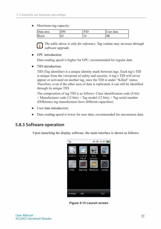
● Maximum tag capacity:
Data area EPC TID User dataBytes 62 16 8K
The table above is only for reference. Tag volume may increase through software upgrade.
● EPC introduction:Data reading speed is higher for EPC; recommended for regular data
● TID introduction:TID (Tag identifier) is a unique identity mark between tags. Each tag’s TID is unique from the viewpoint of safety and security. A tag’s TID will never appear or activated on another tag, once the TID is under “Killed” status. Therefore, even if the other area of data is replicated, it can still be identified through its unique TID.The composition of tag TID is as follows: Class identification code (8 bit) + Manufacturer code (12 bits) + Tag model (12 bits) + Tag serial number (Difference tag manufactures have different capacities)
● User data introduction:
● Data reading speed is lower for user data; recommended for uncommon data.
5.8.3 Software operation
Upon launching the display software, the main interface is shown as follows:
Figure 5-13 Launch screen
5. Commonly use functions and settings

User ManualXC2903 Handheld Reader
23
Explorer: Open the file browser of the system
Control Panel: Open the control panel of the system
View process: Open the process view of the system
PDA: Backlight brightness and sound volume setting of PDA
RFID: Initiate UHF RFID reading function
Barcode: Initiate 1D/2D barcode reading function
TimeSync: Initiate Ethernet time calibration function
Camera: Initiate camera function
Wireless: Power control of Wi-Fi and GPRS modules
Exit: Exit DEMO software
For the functional introduction and application development issues of the DEMO program, please refer to the corresponding directory under “RFID Handheld Universal Demo Software User Manual” in the CD provided.
5.9 Description on API interface program
API interface program is the intermediary between XC2903 and background applications, providing the users with the software interface for secondary development.
For the application of API interface program and development issue pertaining to the application software, please refer to the corresponding directory under “Reader’s Generic API Technical Reference Manual” in the CD provided.
5.9.1 Barcode collection display software
Double click the “Barcode” icon, as shown in figure 5-13, to initiate barcode reading function, click on “Scan barcode” button and point to the desired barcode. Barcode that is read successfully will be displayed as follows:
5. Commonly use functions and settings

User ManualXC2903 Handheld Reader
24
Figure 5-14 Barcode reading
The followings explain the buttons in barcode interface:
“Clear” button is for the clearance of the barcode information collected
“Scan” button is for the single scanning of barcode
For the secondary development of barcode module, please refer to the corresponding barcode module development explanation under “Reader’s Generic API Technical Reference Manual” and “RFID Handheld Universal Demo Software User Manual” in the CD provided.
In order to ensure accuracy and achieve relative short reading time, please make sure XC2903’s barcode window is positioned 20-30cm away from the target. If the barcode is printed on a glossy reflective surface, please maintain a tilt angle of 15°-30° before reading. Failure to do so will affect the reading speed.
Note:
Prior to the usage of this functional module, please make sure the XC2903 model that you purchased has been pre-installed with this functional module. If the module is absent, please contact our sales person for assistance.
5. Commonly use functions and settings

User ManualXC2903 Handheld Reader
25
5.10 GPRS Module Application Overview (Optional module)
The user of this device may choose to install GPRS module, in order to expand the wireless WAN transmission function. The followings elaborate some of the common operations:
5.10.1 GPRS module technical parameters
Working frequency: EGSM900, GSM1800, GSM850, GSM1900
Transmit power: Class 4 (2W) – EGSM900 and GSM850 bandsClass 1 (1W) – GSM1800 and GSM1900 bands
GRPS network connectivity: GPRS multi-slot Class 10GPRS mobile station Class B
SIM card interface: Standard SIM card interface, compatible with 1.8V and 3V
Supported protocols: TCP, UDP, HTTP, FTP, SMTP, POP3
5.10.2 GRPS module application
Preparation:
Insert a valid SIM card into the SIM card slot in the lower left corner of the device’s battery component.
Initiate GPRS module:
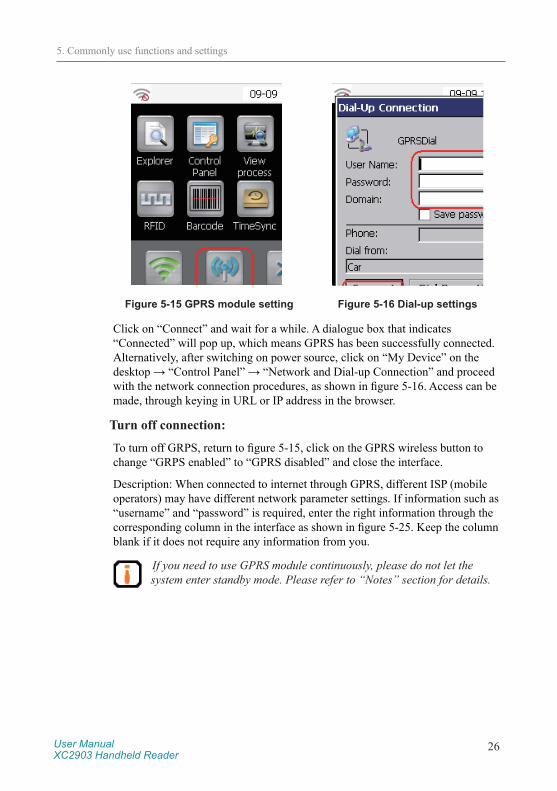
Click on the icon (circled in red) on the bottom left corner of the wireless module setting interface, as shown in figure 5-24. When a dialogue box pops out, click on “GPRS disabled” shown in figure 5-24 to activate the GPRS module. The system will then automatically pop up the dialogue box as shown in figure 5-25. Click on “Connect” to activate the dial-up process.
5. Commonly use functions and settings
User ManualXC2903 Handheld Reader
26
Figure 5-15 GPRS module setting Figure 5-16 Dial-up settings
Click on “Connect” and wait for a while. A dialogue box that indicates “Connected” will pop up, which means GPRS has been successfully connected. Alternatively, after switching on power source, click on “My Device” on the desktop → “Control Panel” → “Network and Dial-up Connection” and proceed with the network connection procedures, as shown in figure 5-16. Access can be made, through keying in URL or IP address in the browser.
Turn off connection:
To turn off GRPS, return to figure 5-15, click on the GPRS wireless button to change “GRPS enabled” to “GPRS disabled” and close the interface.
Description: When connected to internet through GPRS, different ISP (mobile operators) may have different network parameter settings. If information such as “username” and “password” is required, enter the right information through the corresponding column in the interface as shown in figure 5-25. Keep the column blank if it does not require any information from you.
If you need to use GPRS module continuously, please do not let the system enter standby mode. Please refer to “Notes” section for details.
5. Commonly use functions and settings

User ManualXC2903 Handheld Reader
27
6. Accessories description
6.1 Multifunctional cradle (Optional product)Should the users need to charge multiple handheld readers simultaneously, or connect the device(s) through RS232 level wired serial ports, or read and access data through USB flash drive, or have Ethernet communication functionality on multiple XC2903 models, multifunctional cradle products such as XC-AP01001 and XC-AP01112 are available. Both cradles are compatible with XC2903 handheld reader.
The application condition of XC-AP01001 and XC-AP01002 multifunctional cradle is shown in the following table:
Product model Application conditionXC-AP01001 For XC2903 equipped with 3800mAh batteryXC-AP01002 For XC2903 equipped with 5700mAh battery
Figure 6-1 XC-AP01001 multifunctional cradle
1. XC2903 handheld reader port2. USB flash drive port3. 3800mAh lithium battery charging slot 14. 3800mAh lithium battery charging slot 2
6. Accessories description

User ManualXC2903 Handheld Reader
28
Figure 6-2 XC-AP01002 multifunctional cradle
1. XC2903 handheld reader port2. USB flash drive port3. 5700mAh lithium battery charging slot 1
Handheld reader port:The power supply and communication port of XC2903 handheld reader and XC-AP01001 multifunctional cradle; place the handheld reader vertically into the slot to allow metal thimble of XC-AP01001 get in contact with the metal point at the rear end of the reader.
USB flash drive port:The port for USB flash drive; accessible through placing handheld reader into the corresponding slot in XC-AP01001 or XC-AP01002 and insert external 5V DC power supply and USB flash drive into the corresponding slots in XC-AP01001 or XC-AP01002. XC2903F can read the USB flash drive normally and carry out data reading, writing and copying.
If you need to access USB flash drive through XC-AP01001, please insert external 5V DC power supply into the corresponding power slot in XC-AP01001.
6. Accessories description

User ManualXC2903 Handheld Reader
29
7. Product Certification
XC2903 has passed several domestic product quality certification tests and obtained the corresponding certificates. Details of the quality tests are as follows:
No. Name of test Outcome of test Certificate Code1 SRRC Approval Testing Pass CMIIT ID:2013DP80312 FCC Approval Testing Pass TQ4XC29033 IPX5 Waterproof Level Testing Pass ES120508002RC4 UN38.3 Battery Air Transport Detection Pass SET2014-02544
7. Product Certification

User ManualXC2903 Handheld Reader
30
8. Procurement Code
The procurement code of XC2903 handheld reader and accessories is as follows:
No. Product or module Configurations Procurement code1 XC2903 With Wi-Fi, UHF RFID function 30002000472 GPRS module Support 2G network 20204000283 Camera module Only support static photography 20204000304 PSAM card module Support CPU card access function 20204000295 1D/2D barcode module Motorola SE4500 scan engine 2020400044
Honeywell 5100SR scan engine 20204000316 Multifunctional cradle XC-AP01001 2020300062
XC-AP01002 20203000667 Battery 3800mAh/3.7V lithium battery 2020300064
5700mAh/3.7V lithium battery 2020300069
8. Procurement Code

User ManualXC2903 Handheld Reader
31
9. Routine maintenance, FAQs and troubleshooting
9.1 Routine maintenance
Store the device in a cool and dry place, with temperature ranged between +10oC - +40oC. Avoid contact with corrosive substances and keep away from fire and heat sources (For details please refer to 8.2 storage requirement).
Due to the self-discharging characteristics of lithium battery, if the device is not being in use for a long period of time (not less than 1 month), it is recommended that the battery should be removed from the handheld device and stored separately (Battery capacity is best for long term storage at 40%, and should be fully charged and left discharged every three months, if possible).
Precautions for battery usage:
● Do not directly connect the input to output terminal;
● Do not expose the battery to water or get it wet;
● Do not use or store the battery near a heat source (such as fire or heater);
● Please use original charger;
● Do not reverse the positive and negative;
● Do not plug the battery directly in a wall outlet or car cigarette lighter socket;
● Do not put the battery into a fire or heat up the battery;
● Do not use wire or other metal to connect the positive and negative terminals of the battery, do not transport or store the battery with necklace, hairpins or other metallic objects;
● Do not disassemble the battery or cause battery short circuit;
● Do not cause impact to the battery or use sharp object to hit the battery.
9. Routine maintenance, FAQs and troubleshooting

User ManualXC2903 Handheld Reader
32
9.2 FAQs and troubleshooting
This section introduces solutions to some of the common problems or irregularities during the usage of the device.
● How to perform “restart”?
○ Click on the Start menu at the bottom left corner of the main screen, then click on “System Power”→ “Restart”
○ Press the keyboard softkey using stylus, release once the screen turns black. Press the power button to restart, and then proceed with normal startup process.
● No audio
○ Check if system audio has been adjusted to the minimum
● Black screen and no response after clicking
○ Check if the device is in standby mode, click on “On/Off” button to launch the system
● Please check if the battery is loosened
● Unable to read tag
○ Please confirm if the electronic tag is within the effective range of reader;
○ Please confirm if there is any RF signal interference.
● Unable to write tag
○ Please confirm if the electronic tag is within the effective range of the reader;
○ Please confirm if the data area of the electronic tag has been locked;
○ Please confirm if the instruction parameter is configured correctly;
○ Please confirm if there is any RF signal interference.
● Why is the tag writing distance closer than data reading distance?
○ This is due to the special characteristics of RFID technology. Tag writing requires more energy than tag reading, hence the distance is shorter and suc-cess rate of tag writing is much lower as compared to tag reading.
● Why do the reading distances for various tags appear to be so different?
○ This is due to the special characteristics of RFID technology. Different tag chip and their sealing materials have different sensitivity towards the reader;
9. Routine maintenance, FAQs and troubleshooting

User ManualXC2903 Handheld Reader
33
hence the operating distance and success rate are different.
● GRPS is unusable after launching/restarting the system
○ In order to use GPRS module, both power supply and corresponding driver programme are required. Please follow “Introduction on GPRS module application” to connect to the GPRS network. If you wish to use the GPRS module constantly, it is recommended to follow the methods demonstrated in “Power scheme setting”, and change the “Standby” mode to “Never” mode.
● Crashes or white screen occurs during file transfer when the handheld device is under synchronization with PC
○ Unplug the battery and reboot the handheld
○ If the problem persists, you shall proceed as follows:
○ Go to “Control Panel” → “Storage Manager” → select storage device (Flash or TF memory card) and select “Remove” → Once “Format” is successful → enter new name under “New”
After formatting, the data in micro TF card will be lost.
● When Flash or TF card crashes
○ Conduct the following procedures on the reader:
○ Go to “Control Panel” → “Storage Manager” → select storage device (Flash or TF memory card) and select “remove” → Once “Format” is successful → Restart
After formatting, the data in micro TF card will be lost.
● Handheld device unable to start properly (Black screen or crash) after plugging in power adapter or battery
○ Black screen
▫ Check if PC is connected with handheld device through USB data cable. If connected, please unplug the USB cable, and plug in power adapter. Restart the device after that.
▫ Check if the power adaptor is plugged in tightly or the battery is installed properly.
○ System Crash
▫ If there is a progress bar, restart the reader
▫ If there is no progress bar, please contact our sales representative
9. Routine maintenance, FAQs and troubleshooting

User ManualXC2903 Handheld Reader
34
9.3 RF Communication optimization
Under normal circumstances, radio technology is used for device communication. The system performance is very sensitive towards signal interference and attenuation. This section provides some tips for radio communication optimization between XC2903 and electronic tags.
9.3.1 Signal Interference
Signal interference refers to the radio frequency (RF) signal that caused interference to the data exchange between the handheld reader and electronic tag. Signal interference can severely affect the capability of a handheld reader to retrieve information from an electronic tag.
Sources of signal interference
● Radio frequency (RF) system, such as RF local area network and nearby interactive identification system;
● RF signals from security doors, garage doors or other devices
● Other RF radiation sources
When there is radio frequency (RF) interference or noise, the performance of handheld reader (with regard to its data exchange with electronic tag) will be reduced significantly. Handheld reader can only “accept” one signal at any given time, and it is not capable to distinguish between undesirable noise and useful RF signals.
9.3.2 Signal attenuation/reflection
Signal attenuation refers to the natural attenuation of signal strength, resulted from the distance. It may be due to the obstacle encountered in its transmission path.
Possible obstacles for radio frequency signal:
● Enclosed space with concrete walls, floors and ceilings
● Metallic surface surrounding antenna or tag
● Water or other liquid surrounding antenna or tag
Almost every object (including furniture or partition) will cause a different degree of attenuation during transmission process. This attenuation resulted from obstacle can be reduced to the lowest degree through careful repositioning of antenna installation position.
9. Routine maintenance, FAQs and troubleshooting

User ManualXC2903 Handheld Reader
35
At the same time, the reflection caused by metal or metalized surface on the back of the electronic tag may also contribute to signal attenuation. Under some circumstances, this causes slight increase in reading distance and results in blind corners. At these blind corners, the communication between the electronic tag and handheld reader is very poor.
Generally, it is impossible to conduct accurate prediction of the handheld reader system’s performance under any given environment (this is due to the complexity of electromagnetic radiation, including stability of frequency of signal source, antenna pattern, antenna sidelobe, and the surrounding environment). However, some of the recommendations given below can provide a certain degree of guidance in the specific environment, as well as application in optimizing system performance:
● Take into account the radio frequency (RF) characteristic in the surrounding area, including building materials, office hour, windows, and piping configuration. Radio frequency (RF) field mode and reading distance may be affected by metal objects nearby, such as household appliances, equipment and metal frames.
● The electronic tag must remain in the effective reading area of the handheld reader for not less than 100ms (for XC-TF8030-B-C07 electronic tags).
● The optimal antenna length for electronic tag is related to the non-conductive materials sealed or embedded with the tag. Here is the basic concept: For electronic tag embedded within non-conductive materials (The dielectric constant is generally larger than the dielectric constant in the air, causing the effective wavelength of the medium to be shorter than the wavelength of the air) or placed in substrate, if its effective wavelength has been adjusted to the optimal length in open space (at the furthest reading distance from the handheld reader), the electric length of the tag antenna must be reduced to achieve the best effect in open space. On the contrary, if the effective wavelength has been adjusted to the optimal length within non-conductive materials, the electrical length of the tag antenna must be increased to achieve the best effect in open space.
● Do not expose naked, unsealed electronic tag with chemicals. Certain chemicals, such as alcohol, can be corrosive under high temperature, even though they are safe under normal temperature.
9. Routine maintenance, FAQs and troubleshooting

User ManualXC2903 Handheld Reader
36
10. Transportation and storage
10.1 Transport requirements
XC2903 meets all the standard requirements of road, rail, air, and water transportations.
10.2 Storage requirements
The long term storage of XC2903 must meet the following conditions:
● Ambient temperature: -10oC - +40oC;
● Relative humidity: less than 80%;
● No abrupt temperature change, with the absence of acidic gas and other harmful gases;
● Due to the self-discharging characteristics of lithium battery, if the device is not in use for a long period of time (not less than 1 month), it is recommended that the battery should be removed from the handheld device and stored separately.
10. Transportation and storage
User ManualXC2903 Handheld Reader
37
11. Packaging and Unpacking
11.1 Packaging
XC2903 is packed in a box, and transported through large transport container.
11.2 Unpacking
In order to facilitate future storage and transport, keep the box and packaging materials when you unpack the product packaging.
Please check the product and its accessories according to the packing list. Please contact us immediately if there is any discrepancy or damage.
11. Packaging and Unpacking

User ManualXC2903 Handheld Reader
38
12. After-sales
12.1 After-sales service
If you encounter any unsolvable problem when using our product, please contact the customer service center.
Before a user engages our customer service center, please prepare the following information at hand:
● Handheld reader model
● Handheld reader serial number (Located at the bottom of a handheld reader)
● Any changes to the handheld reader or tag
● Application software’s status and condition
12.2 Other matters
If our customer service officer has confirmed with the user to return his/her handheld reader for maintenance, the user will receive a return merchandise authorization (RMA) from our customer service officer. Please indicate the RMA no. on the exterior of the return product packaging and, at the same time, provide the same no. on a piece of paper and place it inside the packaging. This will ensure the quick processing of the return product.
Please follow these steps when returning the handheld reader for maintenance:
● Carefully pack the handheld reader and its accessories into the original antistatic foam box. Please use a box with protective effect if the original box no longer exists.
● Use filler to cover the products in the box.
● Place a note, written with RMA no., in the box.
● Indicate RMA no. and the word “fragile” on the exterior of the box.
12. After-sales

Corporate HeadquartersInvengo Information Technology Co., Ltd.
3/F, No.T2-B, High-tech Industrial Park South, Shenzhen 518057, China
www.invengo.cnTel: (86) 755 26525585 Fax: (86) 755 26525277 [email protected]
US Subsidiary Invengo Technology Corp.
2700-160 Sumner Blvd,Raleigh, NC 27616 ,USA
www.invengo.comOffice: +1 919-890-0202Toll Free: +1 [email protected]