user’s manual - scale service · 4 model 7600 family pwc user’s manual the nci 7600 models are...
TRANSCRIPT

User’s Manual
Model 7600FamilyPostal Weight Classifiers
Model 7620
Model 7680

Model 7600 Family PWC User’s Manual2
Risk of electrical shock. Do not remove cover. No user serviceableparts inside. Refer servicing to qualified service personnel.
Weigh-Tronix reserves the right to changespecifications at any time.
CAUTION
November 29, 2006 7600_U.P65 PN 7424-15384H e2 Printed in USA

Model 7600 Family PWC User’s Manual 3
Table of Contents
Description .......................................................... 4
Specifications ...................................................... 4
Initial Setup ......................................................... 9
Operation .......................................................... 10
7600 Menu Structure ......................................... 14
7600 Menu Structure - Glossary ....................... 15
Diagnostics Mode .............................................. 18
Configuration Mode ........................................... 21
Calibration Mode ............................................... 23
Re-Calibration Mode ......................................... 26
Gravity Mode ..................................................... 28
Review Scale Settings....................................... 30
Communications ............................................... 31
Error Codes ....................................................... 33
Troubleshooting ................................................ 34
Spare Parts Listing ............................................ 37

Model 7600 Family PWC User’s Manual4
The NCI 7600 models are digital electronic letterand parcel bench scales specifically designed formail manifest and shipping applications. They arefast, accurate and reliable. All models use theQuartzell® transducers for true digital signalresponse for increased throughput capabilitiesfor weighing letters, flats and parcels using onescale.
7620-32 70 lb/30 kg0-10 lb x 0.05 oz 10-70 lb x 0.2 oz0-10 lb x 0.002 lb 10-70 lb x 0.02 lb0-5 kg x 0.001 kg 5-30 kg x 0.005 kgn1-5000 n2-6000
7620-50 100 lb/50 kg (100L Mode low res)0-10 lb x 0.1 oz 10-100 lb x 0.5 oz0-10 lb x 0.01 lb 10-100 lb x 0.05 lb0-5 kg x .005 kg 5-50 kg x 0.02 kgn1-1600 n2-5000
7620-50 100 lb/50 kg (100H Mode high res)0-10 lb x 0.05 oz 10-100 lb x 0.5 oz0-10 lb x 0.005 lb 10-100 lb x 0.02 lb0-5 kg x .002 kg 5-50 kg x 0.01 kgn1-3200 n2-5000
7620-75 150 lb/75 kg0-10 lb x 0.1 oz 10-150 lb x 0.5 oz0-10 lb x 0.005 lb 10-150 lb x 0.02 lb0-5 kg x 0.005 kg 5-75 kg x 0.01 kgn1-2000 n2-7500
Default for 100 lbscale
Description
Now an approvedWeights & Measuresresolution
Specifications
Capacity/Resolution

Model 7600 Family PWC User’s Manual 5
7680-75 150 lb/75 kg0-10 lb x 0.1 oz 10-150 lb x 0.5 oz0-10 lb x 0.005 lb 10-150 lb x 0.02 lb0-5 kg x 0.005 kg 5-75 kg x 0.01 kgn1-2000 n2-7500
The 7600 family of bench scales can be used forgeneral weighing applications when configuredas a scale, or for postal and shipping applica-tions when configured as a weight classifier.
Model 7620 is approved as legal for trade:United States - NTEP COC #95-071Canada - Ministry of Industry #AM 5074Europe - EEC (OIML) #UK 2476
For use as a Class III device from +5º to 40ºC
Model 7620:14" L x 12.5" W x 4.2" H356 mm L x 318 mm W x 107 mm H
Model 7680:18" L x 18" W x 4.6" H457 mm L x 457 mm W x 117 mm H
UL/CSA approved inline power supply with 6'long standard wire line cord with ground
Input: 120 VAC + 10% - 15%Output: 15 VDC @ .3 Amps
60 (±3) Hz Standard
AgencyCertificates ofConformance
Frequency
Power Supply
Dimensions

Model 7600 Family PWC User’s Manual6
0.1 amp maximum
42º F - 104º F+5º C to + 40º C10% to 95% RH (non-condensing)
Model 7620:Die cast aluminum base and load bridge.Plastic ABS or stainless steel weigh platter.Aluminum quartz digital load cell
Model 7680:Painted mild steel base with stainless steelweigh platter. Aluminum quartz digital load cell
Model 7620:Adjustable center stopFixed corner stops
Model 7680:Adjustable center stopAdjustable corner stops
400% static loading200% dynamic loading
Internally mounted 1/2" high seven-digit LCDKey panel with ZERO and UNITS function keysOptional remote display with 7ft cable
Level bubble under weigh platterAdjustable feet in each corner
Automatic zero setting is ±10% of maximumcapacity—active at power up. Manual zerosetting range is ± 2% of maximum capacity—active using the ZERO key.
Power Requirements
Operating Temperature
Construction
Overload Protection
Display
Scale Leveling
Zero Window
Model 7600 Family PWC User’s Manual 7
Under Capacity Limits
Over Capacity Limits
Sealing
Internal Resolution
Dynamic Response
Communications
Under capacity indication will be given withdashes appearing on the bottom line of thedisplay whenever the display is more than 10division below the initial zero value.
Over capacity indication will be given with dashesappearing in the upper line of the display when-ever the weighed item exceeds 9 divisions overthe rated capacity of the unit. The scale will usethe initial zero value for reference for overcapacity determination.
Access to the calibration switch can be securedwith a lead wire or pressure sensitive securityseal. The remote and primary indicators have nometrological features that require the use of asecurity seal.
1 part in 2,000,000
The time interval of weight applied to scale until astable weight:
Transmitted Displayed0 - 1000d 500 msec 1200 msec1000d+ 750 msec 1400 msec
Maximum mean average
Factory default settings: 9600 baud, 7 data bits,even parity, 1 stop bit.
Standard 9-pin pass through RS-232 interfacecable included, (not a null modem).
RS-232 bidirectional configurable 1200 to 19.2 Kbaud. Transmits weight and scale status when-ever ASCII “W” <CR> is sent by a remote device.

Model 7600 Family PWC User’s Manual8

Model 7600 Family PWC User’s Manual 9
1. Check container for any obvious evidence ofdamage.
2. Remove contents of the shipping container.
3. Inspect the scale for shipping damage.Immediately report any damage to theshipper.
1. Mount the scale on a stable, level surfacefree from air currents and vibration. Be surethe scale platter does not touch any adjacentsurfaces.
2. To install the scale surface flush with acountertop, use these dimensions to guideconstruction:
Platform Minimum CutoutDimensions Dimensions
7620 14" W 14.75" W12.5" D 13.25" D4.2" Min Ht.
7680 18" W 18.75" W18" D 18.75" D4.6" Min Ht.
3. Loosen the plastic collars (7620) or jam nut(7680) on the leveling feet. Level the scale byusing the level bubble under the scale platteras a guide. Be sure all four feet are in firmcontact with the counter, then tighten allcollars (nuts).
Initial Setup
Unpacking the Scale
Installing the Scale

Model 7600 Family PWC User’s Manual10
4. Make sure all power cords, remote displaycables, etc. are not touching the live weighingsurface.
5. Plug the unit into an appropriate (properlygrounded) voltage outlet.
When the unit is first powered on it will perform atest sequence. During this sequence the displaywill show the following:
• The model number and software revisionlevel
• A numeric counting test of all segments ofthe display
• A test of Random Access Memory (RAM)
• A test of Read Only Memory (ROM)
If everything is OK, the display will show zeroweight and the scale is ready for use.
1. With the scale powered on, make sure thescale platter is empty and the display is atzero. If it is not, press the ZERO key…
0.000 is displayed.
2. Place an item to be weighed on the scaleplatter…
The scale will display the gross weight.
3. Remove the item from the scale platter.
OperationPower Up
Test Sequence
If RAM or ROM erroris reported, you mustpress the UNITS keyto acknowledge thecondition.
Performing a NormalWeighment
If the scale is outsidethe ±10% zerowindow, center dashesare displayed.“_ _ _ _”Reapply power toreset the initial zerosetting.
Model 7600 Family PWC User’s Manual 11
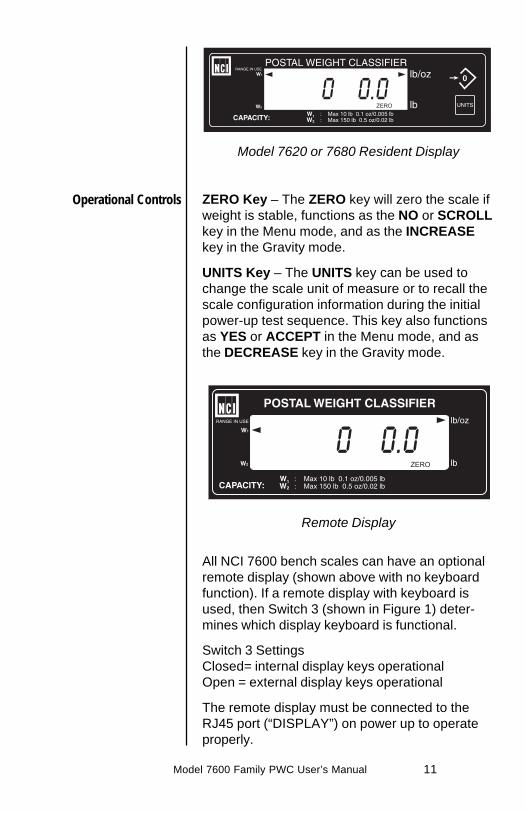
Model 7620 or 7680 Resident Display
ZERO Key – The ZERO key will zero the scale ifweight is stable, functions as the NO or SCROLLkey in the Menu mode, and as the INCREASEkey in the Gravity mode.
UNITS Key – The UNITS key can be used tochange the scale unit of measure or to recall thescale configuration information during the initialpower-up test sequence. This key also functionsas YES or ACCEPT in the Menu mode, and asthe DECREASE key in the Gravity mode.
Remote Display
All NCI 7600 bench scales can have an optionalremote display (shown above with no keyboardfunction). If a remote display with keyboard isused, then Switch 3 (shown in Figure 1) deter-mines which display keyboard is functional.
Switch 3 SettingsClosed= internal display keys operationalOpen = external display keys operational
The remote display must be connected to theRJ45 port (“DISPLAY”) on power up to operateproperly.
Operational Controls

Model 7600 Family PWC User’s Manual12
The 7600 family powers up in normal weighingmode ready for weighing operations. You canaccess the Menu mode by setting Switch 1shown in Figure 1 to the OPEN or Menu modeposition.
Access the Gravity setting mode by settingSwitch 2 shown in Figure 1 to the OPEN orGravity mode position.
Accessing theMenu Mode
Accessing the GravitySetting Mode
Figure 17620 Switch Location
Bottom Viewof Model 7680

Model 7600 Family PWC User’s Manual 13
There are four modes available to you withSwitch 1 in the Menu mode or OPEN position.They are as follows:
1. DIAG Mode – To test areas of the scale’sfunction
2. CONFIG Mode – To configure your scale foryour application
3. CAL Mode – To calibrate the scale
4. Re-CAL Mode – To change specific calibra-tion parameters without having to re-calibratethe scale.
With Switch 2 in the Gravity mode or OPENposition, you may increase the “Local” gravityvalue by pressing the ZERO key or decrease thevalue by pressing the UNITS key.
The structure for these menus is shown in Figure2. Specific information about each mode andstep-by-step instructions for accessing themfollow.
Menu Mode
Gravity Mode

Model 7600 Family PWC User’s Manual14
Figure 27600 Menu Structure
Notes:
(1) The ‘re-calibration values displayed will be the sameas those of the original ‘calibration units of measure.
(2) Will flash “can’t” if originally calibrated for a non-switching kg capacity/resolution.
(3) Will flash can’t if originally calibrated for a non-switching lb capacity/resolution.
(4) To change the ‘Local’ gravity setting, press (and hold)the ZERO key to increase the value, or press (andhold) the TEST key to decrease the value. Whendone, set Switch 2 back to the CLOSED position.

Model 7600 Family PWC User’s Manual 15
30 Calibrates your scale for 30 kilogramcapacity.
50L Calibrates your scale for 50 kilogramcapacity, low resolution.
50H Calibrates your scale for 50 kilogramcapacity, high resolution.
75 Calibrates your scale for 75 kilogramcapacity.
70 Calibrates your scale for 70 poundcapacity.
100L Calibrates your scale for 100 poundcapacity, low resolution.
100H Calibrates your scale for 100 poundcapacity, high resolution.
150 Calibrates your scale for 150 poundcapacity.
Unit on Choosing this option enables theunits key. The units key allows you toswitch between the chosen modes ofmeasurement during calibration.
Unit Off Choosing this option disables theunits key.
7600 Menu Structure - Glossary
Table 1
Table 2
Table 3

Model 7600 Family PWC User’s Manual16
lb kg With "unit on" option enabled,pressing the UNITS key switchesbetween decimal pounds andkilograms.
lb-oz kg With "unit on" option enabled,pressing the UNITS key switchesbetween pounds- ounces andkilograms.
lb-oz lb With "unit on" option enabled,pressing the UNITS key switchesbetween pounds- ounces anddecimal pounds.
1000 g With "unit off" option enabled, thescale displays weight in kilogramswhen calibrated for Kg.
lb ounce With "unit off" option enabled, thescale displays weight as pound/ounce when calibrated as a scale orclassifier. Example: (1 lb .05 oz)
Dec lb With "unit off" option enabled, thescale displays weight in decimalpounds when calibrated as a scale orclassifier.
Table 4
Model 7600 Family PWC User’s Manual 17
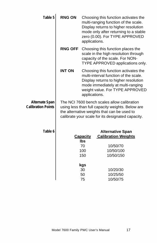
RNG ON Choosing this function activates themulti-ranging function of the scale.Display returns to higher resolutionmode only after returning to a stablezero (0.00). For TYPE APPROVEDapplications.
RNG OFF Choosing this function places thescale in the high resolution throughcapacity of the scale. For NON-TYPE APPROVED applications only.
INT ON Choosing this function activates themulti-interval function of the scale.Display returns to higher resolutionmode immediately at multi-rangingweight value. For TYPE APPROVEDapplications.
The NCI 7600 bench scales allow calibrationusing less than full capacity weights. Below arethe alternative weights that can be used tocalibrate your scale for its designated capacity.
Alternative SpanCapacity Calibration Weights
lbs70 10/50/70100 10/50/100150 10/50/150
kgs30 10/20/3050 10/25/5075 10/50/75
Table 5
Alternate SpanCalibration Points
Table 6

Model 7600 Family PWC User’s Manual18
The Diagnostic (Diag) mode menu lets you testspecific areas of the scale’s function.
These areas are:
Display (DISPLAY) – Shows the version andrevision of the software, followed by a displaysegment test.
RAM (RA) – Performs a nondestructive test ofRAM in the processor. Displays PASS or FAIL.
ROM (RO) – Performs a checksum of all loca-tions in ROM in the processor. Displays PASS orFAIL.
Input/Output (I-O) – Data is output by the scaleand through the use of a loopback connector thedata is immediately read back into the receivechannel and verified against what was sent.PASS or FAIL is displayed. Requires a jumper(short) between transmit (Pin 2) and receive (Pin3) data lines.
Division, test w/AZT (DIV-A) – Weight data isnormalized to 1,000,000 counts of displayedresolution. AZT is enabled (Auto Zero Tracking).
Division, test w/o / AZT (DIV-N) – Weight datais normalized to 1,000,000 counts of displayedresolution. AZT is disabled.
Raw Counts (RA CNTS) – Non-normalized QDTcell data (no zero tracking).
Diagnostics Mode
Diagnostics (DIAG )Mode

Model 7600 Family PWC User’s Manual 19
Follow these steps to access the tests in theDIAG menu (Refer to Figure 2).
1. From normal weighing mode, move Switch 1to the Menu mode or OPEN position.
DIAG is displayed.
2. Press the UNITS key…
DISPLAY is displayed.
3. Press the UNITS key to perform the displaytest described earlier…
Display test is performed and showsDISPLAY after the test is completed.
4. Press the ZERO key…
RA is displayed. This stands for the RAMtest.
5. Press the UNITS key to perform the RAMtest…
PASS or FAIL is displayed briefly. If thetest fails, the unit may have a RAMmemory failure. Try the test a secondtime and if FAIL is displayed, contactyour local Weigh-Tronix dealer forservice.
6. Press the ZERO key…
RO is displayed. This stands for theROM test.
7. Press the UNITS key to perform the ROMtest…
PASS or FAIL is displayed briefly. If thetest fails, the unit may have a programmemory failure. Try the test second time,and if FAIL is displayed, contact yourlocal Weigh-Tronix dealer for service.
Step-by-Step Instruc-tions for DIAG Mode
Press the ZERO key toscroll through lists ofselections.
Press the UNITS keyto make a selection

Model 7600 Family PWC User’s Manual20
8. Press the ZERO key…
I-O is displayed. This stands for theInput/Output test.
9. With a loopback connector in place, pressthe UNITS key to perform the I/O test…
PASS or FAIL is displayed. If the testfails, the unit may have a serial interfacefailure. Check your connections and/orcontact your local Weigh-Tronix dealerfor service.
10. Press the ZERO key…
DIV-A is displayed. This stands for thehigh resolution test with AZT enabled.
11. Press the UNITS key to perform this test…
The display shows the weight on thescale at a resolution of 1,000,000 counts.
12. Press the UNITS key to stop the test…
13. Press the ZERO key…
DIV-N is displayed. This stands for thehigh resolution test without AZT enabled.
14. Press the UNITS key to perform this test…
The display shows the weight on thescale at a resolution of 1,000,000 counts.
15. Press the UNITS key to stop the test…
16. Press the ZERO key…
RA CNTS is displayed. This stands forraw counts.
17. Press the UNITS key to perform this test…
The display shows non normalized celldata.
DIAG will flash every10 seconds during thehigh resolution test toremind you that youare doing a test andnot seeing normalweight readings.

Model 7600 Family PWC User’s Manual 21
18. Press the UNITS key to stop the test.
19. When you are finished with the test, pressthe ZERO key, until DONE is displayed.Press the UNITS key, or place Switch 1 backto normal mode to return to normal weighingmode.
The Configuration (CONFIG) mode menu letsyou configure your scale to your specific applica-tion needs. The items you can configure are asfollows:
Filter (FILTER) – Choose from FLTR ON ORFLTR OFF. Default is FLTR ON. In a stable,vibration free location, the FLTR OFF settingcould be used if quicker display response isdesired.
Baud (BAUD) – Choose one of the followingbaud rates: 1200, 2400, 4800, 9600, and 19200.Default is 9600.
Parity (PARITY) – Choose from: NONE, EVEN,or ODD. Default is EVEN.
Protocol (Prot) – Choose communicationprotocol: NCI STD for standard NCI protocol, NCISMA for Scale Manufacturers’ AssociationStandard for Scale Serial Communications,AS350d for Detecto emulation, or PS6L forMettler emulation. Default is NCI STD.
Configuration Mode
Configuration (CONFIG)Mode

Model 7600 Family PWC User’s Manual22
Follow these steps to access and configure theitems in the CONFIG menu. Refer to Figure 2.
1. From the DIAG display press the ZERO key,or from normal weighing mode, move Switch1 to Menu mode or OPEN position, thenpress the ZERO key…
CONFIG is displayed.
2. Press the UNITS key…
FILTER is displayed.
3. Press the UNITS key…
The current setting is displayed. Use theZERO key to toggle between FLTR ONand FLTR OFF
4. Press the UNITS key…
Filter selection is stored.
5. Press the ZERO key…
BAUD is displayed.
6. Press the UNITS key…
The current setting is displayed. Use theZERO key to toggle between the fivechoices: 1200, 2400, 4800, 9600, or19200 baud
7. Press the UNITS key…
Baud rate selection is stored.
8. Press the ZERO key…
PARITY is displayed.
9. Press the UNITS key…
The current setting is displayed. Use theZERO key to toggle between the threechoices: EVEN, ODD, NONE.
Step-by-StepInstructions for
CONFIG Mode
Press the ZERO key toscroll through lists ofselections.
Press the UNITS keyto make a selection
Tip: Quickly and easilyview current scaleconfiguration directlyfrom the front panelwithout opening thescale or settingswitches as follows:
During the displaysegment test onpower-up, press theUNITS key. Thedisplay will promptABORT followedby BAUD. Press theZERO key to scrollthrough the choices, orpress the UNITSkey to view a currentscale configuration.
When you are done,press the ZERO keyuntil DONE is dis-played. Press theUNITS key to return tothe normal weighingmode.

Model 7600 Family PWC User’s Manual 23
10. Press the UNITS key.
Parity selection is stored.
11. Press the ZERO key…
PROT is displayed.
12. Press the UNITS key…
The current setting is displayed. Use theZERO key to toggle between the fourchoices: NCI STD, NCI SMA, AS350D,PS6L.
13. Press the UNITS key…
Protocol selection is stored.
14. When finished configuring your scale, pressthe ZERO key until the display shows DONE,then press the UNITS key.
Or, move Switch 1 to CLOSED position fornormal weighing mode.
The calibration (CAL) mode menu lets youcalibrate your scale. The items in the calibrationmenu are as follows:
Pounds/Kilograms (LB or 1000g)
Selects the unit of measure of your calibra-tion test weights.
Scale or Classifier
When calibrating the scale for LB, you areable to calibrate the unit as a scale or as aclassifier (weight classifier).
Calibration Mode
Calibration (CAL) Mode
Warning! Entering intothis mode can erasethe calibration alreadysaved. You needapproved calibrationweights to usecalibration mode.
Note: If this procedureis attempted withoutproper calibrationweights applied, thescale will abort theprocess and retain theoriginal calibrationdata.

Model 7600 Family PWC User’s Manual24
Unit On or Unit Off
When configured for UNIT ON, the scale willallow you to switch between the selectedunits of measure using the UNITS key.
Capacity (100, etc.)
Select the capacity of your scale.
Follow these steps to calibrate your scale. Referto Figure 2.
1. From normal weighing mode, move Switch 1to the Menu Mode or OPEN position…
DIAG is displayed. Press the ZERO keyuntil CAL is displayed. This stands forcalibration.
2. Press the UNITS key to start calibration…
LBS or 1000g (kg) is displayed.
3. Press the ZERO key to toggle between thechoices of units of measure (lb or kg). Whenthe choice you want is displayed, press theUNITS key to accept…
If LBS was chosen for calibration, thescale will display the current setting.Press the ZERO key to toggle betweenSCALE and CLASSIFIER. Calibrating asSCALE = .5 division rounding. Calibratingas CLASSIFIER = .9 division rounding.Press UNITS key to accept.
4. The current capacity is displayed. Press theZERO key to toggle between scale capacityselections. Press the UNITS key to accept…
That choice is accepted and UNIT ON orUNIT OFF is displayed.
Step -by-StepInstructions for
CAL Mode

Model 7600 Family PWC User’s Manual 25
5. Press the ZERO key to toggle between thechoices UNIT ON or UNIT OFF. Once yourchoice is displayed, press the UNITS key…
See above for the definitions of calibrat-ing the scale using UNIT ON or UNITOFF.
6. Press the ZERO key to toggle between thechoices. When the choice you want isdisplayed, press the UNITS key…
The scale prompts RNG ON, INT ON, orRNG OFF. See Table 5 in 7600 MenuStructure - Glossary, for definitions ofmulti-range functions.
7. Press the ZERO key to toggle betweenchoices.
8. Press the UNITS key to accept…
The scale then prompts LOAD O.
9. Clear all weight from the scale platter andpress the UNITS key…
After a brief wait LOAD 100 (spanweight) is displayed. Alternate calibrationpoints can be chosen using the ZEROkey to toggle between choices. SeeTable 6 in 7600 Menu Structure - Glos-sary,
10. Place chosen (alternate) calibration weighton the scale and press the UNITS key…
After a brief wait, DONE is displayed.The scale then displays CAL.
11. Remove the calibration weight and returnSwitch 1 to the closed position…
The scale returns to normal weighingmode.
The scale is now tested, configured and cali-brated. It is ready for use in your application.
Close Switch 1 orunplug scale NOW ifyou don’t have correctcalibration weights.

Model 7600 Family PWC User’s Manual26
The re-calibration RE-CAL mode menu lets youchange the scale resolution, rounding method,units and range or interval method without usingany calibration weights.
For a scale originally calibrated in the lb mode,you may also change rounding methods (i.e.scale or classifier).
Follow these steps to re-configure your scale(without weights). Refer to Figure 2.
1. From the normal weighing mode, moveSwitch 1 to the Menu mode or Open posi-tion…
DIAG is displayed.
2. Press the ZERO key until…
RE-CAL is displayed.
3. Press the UNITS key…
ROUND is displayed.
To change the weight rounding method,press the UNITS key. The currentrounding method is displayed.
4. Press the ZERO key to toggle betweenSCALE and CLASS.
5. When the choice you want is displayed,press the UNITS key.
6. To change the capacity/resolution, press theZERO key until RESO is displayed.
Re-Calibration
Can’t will be displayedif originally calibratedfor a non-switchingcapacity/resolution.
Re-Calibration(RE-CAL) Mode
Step-by-StepInstructions
for RE-CAL mode

Model 7600 Family PWC User’s Manual 27
7. Press the UNITS key. The current capacity/resolution setting is displayed.
8. Press the ZERO key until desired capacity/resolution is displayed.
9. Press the UNITS key to select a newcapacity/resolution.
10. Press the ZERO key…
UNITS is displayed. To change theUNITS key status or the current unit ofmeasure, press the UNITS key, thecurrent choice is displayed.
11. Press the ZERO key to toggle between UNITON and UNIT OFF.
12. Press the UNITS key to select the UNITS keystatus and to display unit selections. Tochange units, press the ZERO key to togglebetween the choices.
13. When the choice you want is displayed,press the UNITS key.
14. Press the ZERO key…
RNG-INT is displayed. To changeRANGE operation, press the UNITS key.The current setting is displayed.
15. Press the ZERO key to toggle between RNGON and RNG OFF or INT ON.

Model 7600 Family PWC User’s Manual28
16. When the choice you want is displayed,press the UNITS key.
17. Press the ZERO key.. .
DONE is displayed.
18. Close Switch 1 to return to normal weighingmode.
The Gravity mode feature provides a means ofadjusting the scale’s internal calibration factors tocompensate for variations in acceleration due togravity at different geographic locations. Thesedifferences can cause a given mass to indicate aslightly different weight at an end-user’s (local)site than it did at the Calibration (CAL) site.
To make the adjustment, you must know thevalue of the gravity constant for the local site.This value is expressed in meters per second,per second (i.e., m/s2). It is not necessary tocalibrate the scale, therefore, no calibrationweights are needed to make this adjustment.
The scale maintains two gravity setting values.The first is the “calibration-site” value known asCAL-GR. The second is the end-user or “local-site” value and is known as LOC-Gr. When thescale was originally calibrated at the factory, theCAL-GR and LOC-GR values were both set to9.8040 which is the gravity constant for themanufacturing site.
To adjust the displayed weight value, you mustenter the local gravity value.
Gravity ModeThe CAL-GR andLOC-GR values maybe viewed anytime.See Review ScaleSetting section.
Using this feature insealed applicationsmay be subject toapproval by theappropriate governingagency at the end-users site.
Gravity value roles‘over’ at 9.8400 androlls ‘under’ at 9.7700.

Model 7600 Family PWC User’s Manual 29
To enter the Gravity mode, set Switch 2 to theOPEN position. The display will indicate thecurrent “local” gravity value. Press the ZERO keyto increment the value or the UNITS key todecrement the value. The gravity value willchange in steps of .0001. When the correct valueis displayed, simply return Switch 2 to theCLOSED position. The scale will now use thisnew relationship between calibration and localgravity for its weight calculations.
When the scale is calibrated using calibrationweights, the CAL-GR value is automatically setequal to the LOC-GR setting. Therefore, it isrecommended that you verify the local gravitysetting is accurate before doing a full calibration.

Model 7600 Family PWC User’s Manual30
Pushing the UNITS key during the segment teston power-up, will allow you to view current scalesetup.
When finished viewing the settings, press theZERO key until DONE is displayed. Then pressthe UNITS key to return to normal weighingmode of operation.
Review Scale Settings
Press the ZERO key tomove to the next itemin the menu.
Press the UNITS keyto select the displayitem to view.

Model 7600 Family PWC User’s Manual 31
The NCI 7600 family scales come factory config-ured as a serial RS-232 interface device. Thereis one 9-pin DE type female connector accessibleat the rear of the unit. The functional pinout ofthis connector is compatible with a standard PCpass-through cable.
DE-9 Female Scale DE-9 Male Host
Pin Name Direction Pin Name Direction
1. JMP 1 - 1. DCD IN2. TXD OUT 2. RXD IN3. RXD IN 3. TXD OUT4. JMP 1 - 4. DTR OUT5. SGND - 5. GND -6. JMP 1 - 6. DSR IN7. JMP 2 - 7. RTS OUT8. JMP 2 - 8. CTS IN9. NC - 9. RI IN
The scale uses a DE-9 connector.This standard is used by all NCI bench scaleproducts.
Symbol key:<ETX> End of Text character (03
hexadecimal).<LF> Line Feed character (0A hex).<CR> Carriage Return character (0D hex).<SP> Space (20 hex).x Character from display including
minus sign.hhh Three status bytes.uu Unit of measure using ANSI standard
abbreviations
Communications
Interface Cable
NCI STDCommunications
Protocol
* Jmp1 and Jmp2 pinsare connectedinternally on the scalePCB connector.
Model 7600 Family PWC User’s Manual32
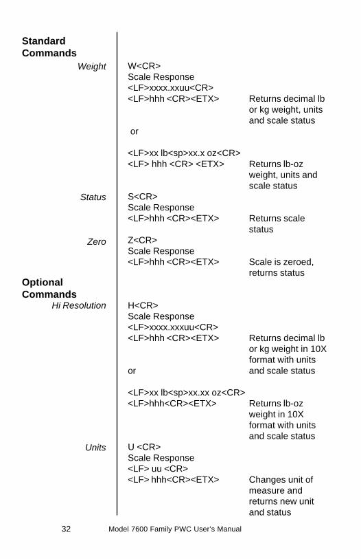
W<CR>Scale Response<LF>xxxx.xxuu<CR><LF>hhh <CR><ETX> Returns decimal lb
or kg weight, unitsand scale status
or
<LF>xx lb<sp>xx.x oz<CR><LF> hhh <CR> <ETX> Returns lb-oz
weight, units andscale status
S<CR>Scale Response<LF>hhh <CR><ETX> Returns scale
statusZ<CR>Scale Response<LF>hhh <CR><ETX> Scale is zeroed,
returns status
H<CR>Scale Response<LF>xxxx.xxxuu<CR><LF>hhh <CR><ETX> Returns decimal lb
or kg weight in 10Xformat with units
or and scale status
<LF>xx lb<sp>xx.xx oz<CR><LF>hhh<CR><ETX> Returns lb-oz
weight in 10Xformat with unitsand scale status
U <CR>Scale Response<LF> uu <CR><LF> hhh<CR><ETX> Changes unit of
measure andreturns new unitand status
StandardCommands
OptionalCommands
Weight
Status
Zero
Hi Resolution
Units
Model 7600 Family PWC User’s Manual 33
M<CR>Scale Response<LF>xxxxxxxMM<CR><LF>hhh <CR><ETX> Returns normalized
raw counts andstatus
All other commandsScale Response<LF>?<CR><ETX> Unrecognized
command
Contact your Weigh-Tronix service provider orthe Weigh-Tronix customer service departmentfor protocol.
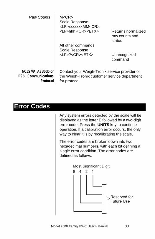
Any system errors detected by the scale will bedisplayed as the letter E followed by a two-digiterror code. Press the UNITS key to continueoperation. If a calibration error occurs, the onlyway to clear it is by recalibrating the scale.
The error codes are broken down into twohexadecimal numbers, with each bit defining asingle error condition. The error codes aredefined as follows:
Error Codes
NCI SMA, AS350D orPS6L Communications
Protocol
Raw Counts

Model 7600 Family PWC User’s Manual34
Perform the following steps in the order pre-sented until the described problem is corrected. Ifthe problem cannot be corrected, contact anauthorized Weigh-Tronix service provider.
No Power (Display is Blank)
1. Check that the primary side of the cord isplugged into the AC outlet, and the second-ary side is properly connected to the powerjack on the back of the scale.
2. Replace the power supply.
3. Replace the display board.
4. Replace the I/O board.
5. Replace the QDT load cell.
Missing or extra segments on display
1. Replace the display board.
2. Replace the QDT load cell.
Troubleshooting

Model 7600 Family PWC User’s Manual 35
Scale will not return to zero, or incorrectweight is displayed
1. Press the ZERO key.2. Check for interference of weighing platform.3. Power off, remove all items from the platter,
and then power on the scale.4. Recalibrate the scale.5. Replace the QDT load cell.
Display shows unrecognized characters
1. Check software PROM for proper insertion.2. Check display cables for the proper connec-
tion.3. Replace the display board.4. Replace PROM.5. Replace the QDT load cell.
Display shows under “_ _ _ _” dashes
(Indicates that the scale is below zero or undercapacity.)
1. Verify that weigh platter is on the scale.2. Press the ZERO key.3. Power off, remove any items from the platter,
and then power on the scale.4. Recalibrate the scale.5. Replace the QDT load cell.
Display shows center “_ _ _ _” dashes
(Indicates that the scale is outside zero capacityof ±2%.)
1. Verify that weigh platter is on the scale.2. Press the ZERO key.3. Power off, remove any items from the platter,
and then power on the scale.4. Recalibrate the scale.5. Replace the QDT load cell.

Model 7600 Family PWC User’s Manual36
Display shows upper “ _ _ _ _ “ dashes
(Indicates the scale is over capacity.)
1. Remove all items from the scale.2. Press the ZERO key.3. Power off, and then power on the scale.4. Recalibrate the scale.5. Replace the QDT load cell.
Scale is not transmitting data to the hostdevice
1. Check cable connection at both the rearof the scale and the host device.
2. Check communication setting and baudrate on both the scale and host device.
3. Perform I/O loopback test.4. Replace the cable.5. Replace the I/O board.6. Replace the QDT load cell.
The ZERO key and the UNITS key do nofunction
1. Check the position of Switch 3. Closed forinternal display keypad active. Open forexternal display keypad active.
2. Open display enclosure and verify that thekeypad cable is still installed correctly.
3. Replace the display panel.4. Replace the display PCB.5. Replace the display cable.6. Replace the I/O PCB.7. Replace the QDT load cell.
Model 7600 Family PWC User’s Manual 37
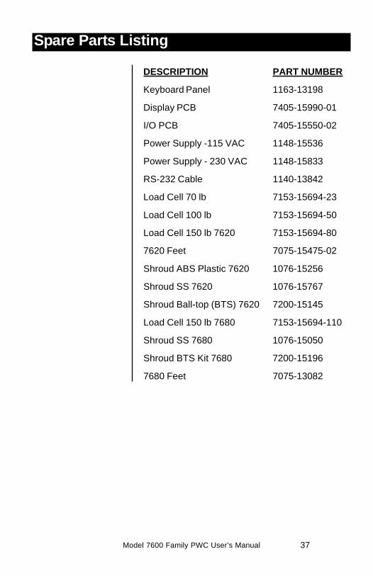
DESCRIPTION PART NUMBER
Keyboard Panel 1163-13198
Display PCB 7405-15990-01
I/O PCB 7405-15550-02
Power Supply -115 VAC 1148-15536
Power Supply - 230 VAC 1148-15833
RS-232 Cable 1140-13842
Load Cell 70 lb 7153-15694-23
Load Cell 100 lb 7153-15694-50
Load Cell 150 lb 7620 7153-15694-80
7620 Feet 7075-15475-02
Shroud ABS Plastic 7620 1076-15256
Shroud SS 7620 1076-15767
Shroud Ball-top (BTS) 7620 7200-15145
Load Cell 150 lb 7680 7153-15694-110
Shroud SS 7680 1076-15050
Shroud BTS Kit 7680 7200-15196
7680 Feet 7075-13082
Spare Parts Listing

Model 7600 Family PWC User’s Manual38

Model 7600 Family PWC User’s Manual 39

1000 Armstrong DriveFairmont, MN 56031Telephone: 507-238-4461Facsimile: 507-238-4195E-Mail: [email protected]