user’s manual stand alone dvr 00a24n revision date : 2005. 03. 15. firmware 2.4 version
TRANSCRIPT

USER’S
MANUAL
Stand Alone DVR
00A24N
Revision Date : 2005. 03. 15.Firmware 2.4 Version

2
• Specification & Organization
2. Product contents List Please Confirm the Contents When open Package.
① Basic Contents
① Option Contents
00A24N
Remote ControllerUser’s Manual
Remote Client Program Install CD
AAA Battery X 2
HDD VGA OUT Install Kit
12V Adaptor Power Cable
CD-RW (400SN)

3
• Specification & Organization
3. Organization (400SN)
NETWORK
Camera #1-4
Alarm Sensor #1-4 Relay Out
VCR VGA Monitor AV
Monitor
Remote Client PC Image Printer
00A24N
Video In
Video Out
TCP/IP
Alarm Input/Out
Remote Controller
CD-RW
Backup
AVI Backup
WEB Client

4
• Description
① Power : System Power On/Off.
② Remote Controller Sensor Input.
③ CD-RW : CD-RW Device for Backup.
④ Led Indicator : Indicate Present System Status Information. ( POWER: System On/Off , RECORD: Record On/Off , NETWORK: Client Network Connection Status ALARM: Alarm Sensor Detection Status )
⑤ Channel Selection Button : Select Channel or Input Password.
⑥ SCR MODE : Select Screen Division Mode or Rotation Mode.
⑦ SEARCH : Go to Search Mode for Searching Data.
⑧ MENU : Go to System Menu.
⑨ PTZ/FOCUS : Go to Camera PTZ/FOCUS Control.
⑩ Search Controller : Searching Recorded Data or Control Menu & PTZ/FOCUS.
⑪ ENTER : Apply Changing Setup.
⑫ RETURN : Cancel Setup or Return to Previous Mode.
Tip
1. Front Panel
①
② ③
④
⑤ ⑥ ⑦
⑧ ⑨
⑩
⑪ ⑫
• Power Button is Soft Style to Prevent System Failure by Wrong Operation.
• Channel Selection Button is Prior to SCR Mode.
• When Remote Controller Sensor Input is Blocked by Something, it Cause 1 Remote Controller do NOT Work Properly.
• When Press any Button, it Operate with Beep Sound.
• In Case of CD-RW, the Real Appearance will be Differ from the above Picture 1 Depends on its Model.

5
• Description
① Video In : BNC Port for Connection of DVR & Camera. (4 Camera Connectable)
② Loop Back : Output DVR Camera Video to Loop Back Port. (4 BNC Port)
③ Monitor Out : Output DVR Video to AV Monitor.
④ Spot Out : Output Spot-out Video to AV Monitor.
⑤ NTSC/PAL : Select NTSC or PAL Type.
⑥ VGA OUT : Output Video to a Computer Monitor by Connected VGA.
⑦ SVHS : Output Video by Connected SVHS.
⑧ Audio Out : Output Audio Data.
⑨ Audio In : Audio Input Terminal Related with #1~4 Camera.
⑩ Ethernet (TCP/IP) : Port for Cross cable. (Possible to Remote Surveillance.)
⑪ Alarm/Relay/RS-485 : Connect Port for Sensor, Relay, & PTZ.
⑫ RS-232C : Connect Port for Program Debug.
⑬ DC Power Input : Power Supply by DC 12V Adaptor.
Tip• When System Installation, Please Install under System Power Off Status.
• Please Use Specific Adaptor when Power Supply.
2. Rear Panel
① ③
④ ⑤
⑥ ⑨
⑧ ⑩
⑪
⑬② ⑦
⑫

7
• Description
POWER
System ON/OFF
MENU: Open Menu
RETURN
Cancel Setup or Return to Previous
ENTER: Apply Setup Change
Channel Selection Button(4ch Available, #1~4 Button)
Change Screen Mode
Open Search Mode
PTZ/IRIS Mode
• Unused Button’s Description is Omitted.
• Every Button is Operated Same as Front Panel Button.
• Remote Controller can Operate when Remote Controller Sensor Input Part Reacted Each Other.
※ If there are many DVR at the same place, they are reacted together when press remote controller.
Search Controller : Control Playback Option, Menu Movement, PTZ/Focus Control
3. Remote Controller

8
• Display
Tip
CHANNEL
1. System Power ON
CAMERA
2004/01/01 00:00:00
• Press Power Button to Start System
• After Checking Hard Disk, Need input Password to 1 Operation
• Initial Screen View Mode is Quad Division Mode 1 and Recording Mode
Picture for Power On after Finishing Installation • Each Channel Indicate Camera Name & Recording
Status
• Present Time & Date Indicate at Monitor Central Lower Side
• Check System Condition at LED
POWER : Showing System On/Off RECORD : Showing Record On/Off NETWORK : Showing Client Connection Status ALARM : Lighting when Sensor Alarm Activate
2. Select Screen Mode
• Select One Channel among 4 Channels
• Move to One Enlargement Watch Mode when Quad Screen Division Mode
• Move to One Enlargement Watch Mode when Rotation Mode

8
• Display
SCR MODE
PTZ/FOCUS
3. Screen Rotation Mode (SCR MODE)
• User can Select 3 Kinds Watch Mode
① Quad (4CH) Division Watch Mode
② Selected 1CH Watch Mode
③ 4CH Rotation Watch Mode
• Quad (4CH) Watch Mode is Initial Mode when System Start
Quad (4CH) Division Watch Mode
Selected 1CH Watch Mode
4CH Rotation Mode
4. PTZ/FOCUS Control
• Control Camera PTZ (Pan/Tilt/Zoom) & Focus (Only Useable for Proper Camera)
• Press PTZ/FOCUS Button to Open PTZ Menu at Right-Under Side and Control by
1 Search Controller
• Press PTZ/FOCUS Button Second Time to Open FOCUS/IRIS, PRESET, SWING
Menu and Control by Search Controller

PTZ CTL UPLEFT RIGHT DOWN
FOCUS/IRISCTL UPLEFT RIGHT DOWN
PTZ/FOCUS
PRESETNUMBER:1
NUMBER CHANGE:UP/DOWNSET:F1 GOTO:F2
SWINGMODE:PAN SWING
NUMBER CHANGE:UP/DOWNFIELD CHANGE:LEFT/RIGHT
SET:F1 RUN:F2
1. PTZ Control• Press PTZ/FOCUS Button to Open PTZ Menu at Right-Under Side and Control by 1 Search Controller
• When Press PTZ/FOCUS Button by Turns, Focus/Iris, Preset, Swing Menu will 1 Appear at the Right-Under Side and possible to Control by Search Controller.
Fast Backward
Backward Play
Search Controller
Play Fast Forward
1.1 PTZ Control
① Control Camera Movement by ‘Faster’, ‘Slower’, ‘Backward Play’, ‘Play’ Button (Up,Down.Left,Right).
② Zoom In & Out by ‘Fast Backward’, ‘Fast Forward’ Button.
③ Keep Press Button Make Continuous Movement.
1.2 FOCUS/IRIS Control
① Control Iris by ‘Faster’, ‘Slower’ Button.
② Focus On by ‘Backward Play’, ‘Play’ Button.
③ Zoom In & Out by ‘Fast Backward’, ‘Fast Forward’ Button.
④ Keep Press Button Make Continuous Movement.
• Display
9

PRESETNUMBER:1
NUMBER CHANGE:UP/DOWNSET:F1 GOTO:F2
SWINGMODE:PAN SWING
NUMBER CHANGE:UP/DOWNFIELD CHANGE:LEFT/RIGHT
SET:F1 RUN:F2
1.3 PRESET Control
① By Preset Function, Possible to Setup Direction and Focus of PTZ Camera.
② After Selecting Position at PTZ Control Mode, Save Data at Preset Mode.
③ Setup ‘NUMBER’ from 1 to 128 by ‘Faster’ & ‘Slower’ Button.④ Save by Front Panel Key No.1 Button or F1 Button on Remote Controller.
⑤ To Move to Saved Location, Press Front Panel Key Button No.2 or F2 Button on Remote Controller.
⑥ It support at Protocol D/Protocol P/D-MAX only.
※ In protocol D case, It have to keep the memory after memorable setting are deleted.
1.4 SWING Control
① SWING Function Dedicate Each No. of Saved Preset and Swing as Pan or
Tilt.
② Changing Mode by Backward Play Button.
Changing Setup by Faster, Slower Button.
③ PAN SWING MODE : Rotate Left , Right Side. TILT SWING MODE : Rotate Up, Down Side. START PRESET : Select Starting Point. (1~128) END PRESET : Select End Point. (1~128) SWING TIME : Select Halt Time as Each Point. (1~64sec) SWING SPEED : Select Moving Speed of Camera. (1~64)
④ Save by Front Panel Key No. 1 Button or F1 Button on Remote Controller.
⑤ For Start SWING Mode, Press Front Panel Key No.2 or F2 Button on Remote Controller.
⑥ It support at D-MAX only.
Tip • All ability work by camera is supported each protocol.
• Display
10

• Display
5. System Power OFF
Tip
• Press Power Button to System Off
• Input Password and Press Enter to Shutdown System
• System Log-On Possible ID : ‘Administrator’, ‘Manager’, ‘Operator’
Administrator: All Function Access (System On, Shutdown, Setup, Search)Manager: System On and SearchOperator: System On
11
• SEARCH
SEARCH
ENTER
RETURN
2004/01/0100:00:00 >
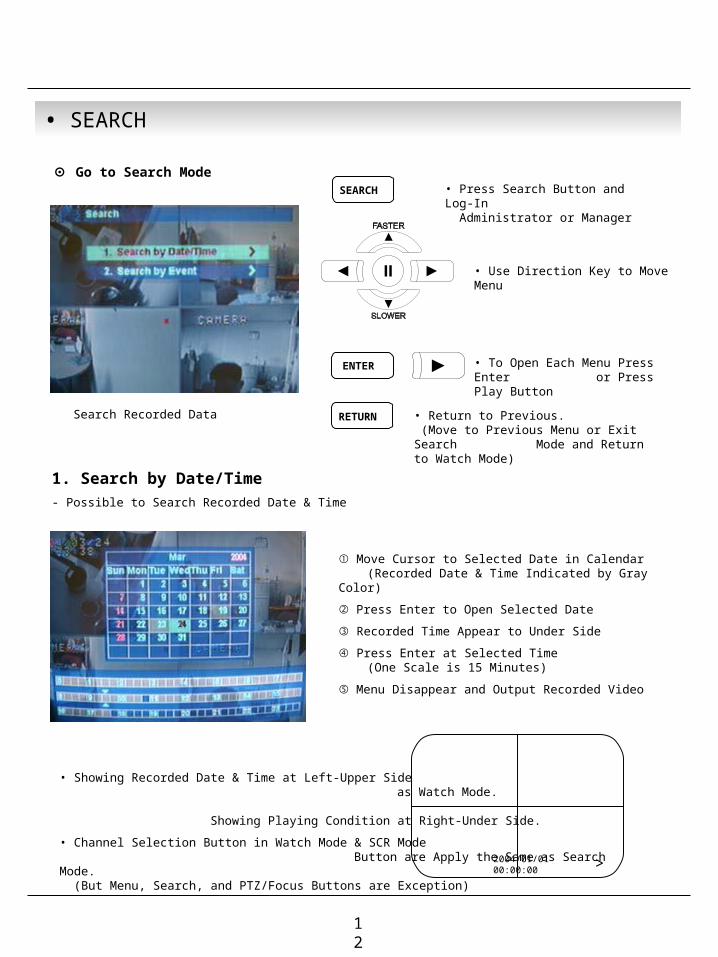
⊙ Go to Search Mode• Press Search Button and Log-In
Administrator or Manager
• Use Direction Key to Move Menu
• To Open Each Menu Press Enter 1 or Press Play Button
• Return to Previous. (Move to Previous Menu or Exit Search 1 Mode and Return to Watch Mode)
Search Recorded Data
1. Search by Date/Time- Possible to Search Recorded Date & Time
① Move Cursor to Selected Date in Calendar (Recorded Date & Time Indicated by Gray Color)
② Press Enter to Open Selected Date
③ Recorded Time Appear to Under Side
④ Press Enter at Selected Time (One Scale is 15 Minutes)
⑤ Menu Disappear and Output Recorded Video
• Showing Recorded Date & Time at Left-Upper Side 1 as Watch Mode. 1 Showing Playing Condition at Right-Under Side.
• Channel Selection Button in Watch Mode & SCR Mode 1 Button are Apply the Same as Search Mode. (But Menu, Search, and PTZ/Focus Buttons are Exception)
12

• SEARCH
Tip
• Control Playing Video
① : Basic Playing Mode (Normal Speed (1X) Forward Playing)
② : Normal Speed Backward Playing
③ : Pause Video
④ : Fast Forward (2 ~ 64 Speed)
⑤ : Fast Backward (2 ~ 64 Speed)
⑥ : Same Function as # ④,⑤
※ Press Normal Forward/Backward Button in Pause, Move to Next/Previous Frame.
2. Search by Event- Searching Video with Event Occurrence to Set up Period
Set up Period to Select Start Date & Finish Date for Searching Event
Alarm : Searching Alarm Event during the Selected 1 Period
Motion : Searching Motion Detected Event during 1 the Selected period .
Timer : Searching Schedule Change or Recording 1 Setup Change Event
System : Searching Power On/Off Event (etc.) 1 Concerned System Event
Event List Showing at Below Output Window
• Alarm, Motion, System can be Select plural by Check (V)-(ENTER)
• To Change Setup, Press Enter and Press Direction Key After Changing Setup, Press Enter to Exit.
13

• SEARCH
Tip
• Date : Indicate Event Occurrence Order & Date
Time : Indicate Event Occurrence Time
Event : Indicate Event Contents & Camera No.
• Event Searching Method
① User can Search Event Using by Direction key
② Search Event to Press Enter at Selected Event from Event Occurrence Time
③ Control Video is the same way as Time Mode Control
• The Search by Event is not Base on Video, but Event Occurrence Time.
14

15
• MENU
Tip
• ENTER
RETURN•
⊙ Go to Menu
① Press Menu Button on Front Panel in Watch Mode
② Ask Password
③ Input Password Using by Channel Select Button 1 [1][2][3][4])
④ After Input Password Press Enter to See Menu
• Initial Administrator, Manager, Operator Password is 1234.
• Showing Password as *
• Changing Password (MENU->6.System->4.Password )
• Only Watch Mode can go to Menu. (Search & PTZ/Focus Mode can’t move to Menu)
⊙ Menu Initial
• Every System Setup can Change or Maintain 1 at Menu (6 Setup)
• Move to Menu Using by Up & Down Button
To Open Detail Menu or to Apply Input
Return to Previous Menu or Return to Watch Mode

16
• MENU
1.Display - Video Setup for Watch Mode
1. Date/Time : Date & Time Mark On/Off
2. Title : Camera Name On/Off
3. Status : Record Condition Mark On/Off (Recording: Red, Pre-recording : Green)
4. Border : Border Mark On/Off when 4CH Division Watch Mode
5. Border Color : Select Border Color(White, Blue, Red, Yellow, Green, Gray)
6. Sequence Dwell : Setup Rotation Cycle Time (1~60 Sec.) when 4CH Rotation Mode at Watch Mode
7. Spot-Out Dwell : Setup Spot-Out Time Cycle (1~60 Sec.) to Transmit Video
8. Deinterlace Mode : Remove Screen Spread on High Resolution , Low Frame ※Only Applying When D1(704X480)
2.Record - Setup Image Record
2.1 Size/Rec.Rate/Quality – Setup Recording Resolution, Compression Rate, Quality
-Camera : Indicate Camera No. to Setup -Size : Setup Resolution -Rec.Rate : Setup Compression Rate -Quality : Setup Quality of Recording Video

17
• MENU
Overlimit Recording Capacity
Tip
• Size : 352*240, 704*240, 704*480
Rec.Rate : Possible to Select (1~30)
Quality : Possible to Select 3 levels (High, Low, Standard)
• Indicate Frame No. to Control Size & Rec. Rate
• If Frame Over, Showing a Message ‘Overlimit Recording 1 Capacity’ and Impossible to Change Size & Rec. Rate
• When Setup Refer to Below NTSC, PAL Type
NTSC : 352*240(120fps), 704*240(60fps), 704*480(30fps) PAL : 352*288(100fps), 704*288(50fps), 704*576(25fps)
• Possible to Setup Size & Rec. Rate, Quality per Each Channel
• When Applying Change Setup, Press Enter, 1 When Cancel Change Setup, Press Return.
2.2 Timer Recording Setup – Record On/Off or Time, Motion Setup
• Camera : Indicate Camera No. to Setup
• Record : Record On/Off
• Start : Setup Recording Start Time (0~24 hr)
• Stop : Setup Recording Finish Time (0~24 hr)
* Recording Time is between Start Time and Finish Time.
• Motion : Motion Detection Recording On/Off (Record Setup must be ‘On’, when Motion Detection 1 Recording.)

18
• MENU
Tip
2.3 Motion Detection Setup – Motion Detection Area & Sensitivity
• Camera : Indicate Camera No. to Setup
• Sensitivity : Control Sensitivity (1~100)
Large No. is More Sensitive.
• Region : Setup Motion Detect Range
Entirely – Setup Entire Screen
Partially – Setup Partial Screen
• When Choose Region as Partially, Move to Partial
1 Range Setup. Press Enter After Partial Range
Setup 1 to Finish Region Setup.
• Pre-Motion Duration : Setup Pre-Motion Duration Time. 1 (1~5 sec)
• Post-Motion Duration : Setup Motion Detect Recording 1 Time after Motion Detected (5sec~3min)
2.4 Alarm Recording Setup – Recording Setup for Alarm Activated
• Camera : Indicate Camera No. to Setup
• Record : Setup Record On/Off when Alarm Activated
• Start : Setup Alarm Recording Start Time (0~24 hr)
• Stop : Setup Alarm Recording Finish Time (0~24 hr)
• Pre-Alarm Duration : When Alarm Recording, Setup 1 Start Recording Time before Alarm Activate (1~5sec)
• Post-Alarm Duration : Setup Alarm Recording Time 1 after Alarm Activate (5sec~3min)
• Motion Setup Work by Time Schedule and Alarm Schedule Work Independently.

19
• MENU
① ②
③ ④
⑤ ⑥
⊙ Time Recording Weekly Setup
Weekly mode Setup at Record Setup Scheduled Region Indicated Yellow
After ‘Deselect’ Schedule, Activated Region by Press ‘ENTER’ and Select Date & Time to Move Cursor
After Selecting Region and Press ‘ENTER’ Again to Finish Schedule Setup (Red)
Setup Date & Time Schedule in the Same Way. After Finishing Schedule Setup, Press ‘Return’ for Save & Exit
• Select All : Entire Region Select• Deselect All : Cancel Region• Save&Exit : Save Changing Setup & Exit • Cancel : Cancel Changing Setup & Exit

20
• MENU
① ② ③
④ ⑤ ⑥
⑦ ⑧
⊙ Partial Motion Region Setup
:Non-Activate Move Cursor :Activate Partial Setup Cursor :Partial Setup Finish Cursor :Non-Activated Region
Region Initial View Move Cursor by Direction Key and Press Enter at Selected Region
Press Enter again to see Region as a Blue Color and Setup Non-Activate Region
When Select Multi Region, Using Direction Key in ② to Expand Non-Activate Region
Press Enter to Select Multi Non-Activate Region
Same Method as ④⑤, Possible to Expand Non-Activated Region
For Reducing Partial Region, Cancel Non-Activate Region in Same Way as ④⑤
When Finishing Partial Region Setup, Press Enter to Save & Exit
• Select All : Select Entire Region
• Deselect All : Cancel Region Setup
• Save&Exit : Save the Change Setup & Exit
• Cancel : Cancel Change Setup & Exit

21
• MENU
Tip
3.2 Covert/PTZ Setup
3.Camera - Setup Camera
3.1 Status/Title Setup – Camera Connection Status & Camera Name Setup
• Camera : Indicate Camera No. to Setup
• Status : Indicate Camera Status (Connected/Disconnected)
• Title : Setup Camera Name to Show Left-Upper Side
• Title Input Method
Using Direction Key, Up & Down Keys for Alphabet A~Z, Numerical No. 0~9 1 Left-Right Keys for Move to another Letter.
• Camera : Indicate Camera No. to Setup
• Covert : Setup Covert On/Off *What’s Covert? When Covert On Watch Mode, Display Video is 1 1 Hidden, but Recording is On.
• PTZ Address : Select PTZ Camera Address
• PTZ Protocol : Select Kind of PTZ Camera
• Baud Rate : Setup PTZ Communication Speed (2400, 4800, 9600 BPS)※PTZ Supplied Protocol :Samsung(MRX-1000), Samsung(SCC641),Honeywell(SD1)Honeywell((GMC),Lilin(Fastdome), Fastrax(Ⅱ), GC(655H),D-MAX, Sunin DSC-230, Scan Dome-Ⅱ, Vicon, Sensormatic,Panasonic(WV-CS850), Panasonic(WV-CSR604),Kalatel(KTD-312), PELCO-D, PELCO-P

22
• MENU
Tip
3.3 Color Setup – Control Video Color
• Camera : Indicate Camera No. to Setup
• Bright : Control Monitor Bright
• Contrast : Control Monitor Contrast
• Color : Control Monitor Color
• Tint : Control Monitor Tint
* All Setup Possible to Control 0~100
4.Audio - Setup Audio
4.1 Audio Recording Setup – Audio In Setup
• Camera : Indicate Camera No. for Setup
• Audio Rec. : Setup Recording On/Off from External 1 Audio In Terminal
• Audio Ch. : Setup Audio In Terminal Channel & 1 Audio Output Camera
• User can Listen Saved Audio with Saved Video
• Audio Check in Search is Possible Only Normal Speed (1X) Forward 1 Playing at 1CH Mode (Audio Recorded Channel)

23
• MENU
Tip
4.2 Live Audio Setup – Audio Out Setup
• Live Audio : Audio Output ON/OFF Live Audio Output from Audio In Terminal
• Monitoring Ch. : Select Channel for Audio Output 1 Nr. 1~4 Audio In
5.Alarm - Setup Alarm & Relay
5.1 Alarm Input Setup – Alarm Sensor Setup
• Alarm : Indicate Alarm Input Terminal No.
• Status : Setup Alarm Sensor Connection Status (Connected/Disconnected)
• Camera : Input Camera No.1~4 to Connect Alarm
• Type : Setup Alarm Sensor N/Open, N/Close Type
• Generally Alarm Sensor can be Divided Two Types.
Normal Open Type is Open Sensor Electrically and Reacted when 1 Signal is Connected. Normal Close Type is Close Sensor Electrically and Reacted when 1 Signal is Disconnected.
• Network Audio
① Enter ‘4.Audio -> 4.2 Live Audio Setup’ at the Menu.
② Select ‘One-way’ or ‘Two-way’ at the Network Audio.
③ One Way : Transfer Audio from DVR to Remote Client. Remote Client Possible to Receive Audio with Video.
④ Two Way : Communicate Audio between DVR and Remote Client. Remote Client Possible to Receive & Send Audio to DVR Server.
⑤ Network Audio Possible to Operate even Live Audio Off.

24
• MENU
Tip
5.2 Relay Output Setup – Alarm Relay Setup
• Alarm : Indicate Alarm Input Terminal No.
• Relay Out : Setup Relay Connect with Alarm Sensor
• Mode : Setup Reacted Relay as Latched/Transparent Mode
• Duration : Setup Reacted Relay Time 1 (5sec~5min or Until key-in)
• Relay Type : Setup Relay Type N/Open or N/Close
• Latched/Transparent
Latched – When Sensor Alarm Activated, Relay Reacted in Setup Duration Transparent – Relay Reacted Temporary During Sensor Alarm Activate
6.System - Basic Environment Setup
6.1 Date/Time – Date & Time Setup
• Date : Setup Present Date (YYYY-MM-DD). (If Time Setup to Past Date, Ask Delete Data for the Past Date. NO->Date/Time No Change, YES->After Delete Past Data and Change Date/Time )
• Date Format : Select Date Output Type (Ex: 2004-00-00, 2004/00/00)
• Time : Setup Present Time
• Time Format : Setup Time Type as 12 Hour Base or 24 Hour Base
• Daylight Saving : Summer Time Applying Status

• MENU
6.2 Network – Setup TCP/IP
<DHCP ON, DDNS OFF> <DHCP ON, DDNS ON>
<DHCP OFF, DDNS OFF> <DHCP OFF, DDNS ON>
25
※ If your network connect at the router, please must port forwarding. Otherwise you can't receive the service well.
• Press the NEXT button and progress the step.
• Don’t change the DDNS name because it is fixed the domain name.
• IP Address : Input IP Address
• Gateway : Input Gateway IP for Internet Server
• Subnet Mask : Input Subnet Mask IP
• Network Speed : Setup Network Speed (Network Speed from System, Depend on Network Status)※ If Change Network Setup, New Change Apply when after Rebooting.

• MENU
Possible to Confirm IP Address for the DVR at the System Information.
DDNS
DDNS(Dynamic DNS): You can connect the DVR by the fixed domain name(ex.00115f000001.dvrlink.net) at client or Web without entering the IP address.1. Enter to ‘6.System -> 6.2 Network' on the menu.2. Setup DHCP On or Enter the IP address.3. Setup DDNS ON and reboot.4. Enter to ‘6.System -> 6.6 System information’on the menu.5. Confirm the MAC address.6. The domain name is "MAC address.dvrlink.net". EX) If Mac Address is 00-11-5f-00-b5-a7, the domain name is "00115f00b5a7.dvrlink.net"7. If you connect by "00115f00b5a7.dvrlink.net" at client program or Web, you can connect the DVR.
※ 1. If your network connect at the router, please must port forwarding. 2. Please, you must enter the exact IP address, DNS Server, Gateway, Subnet Mask. 3. Please you must connect the DVR at External Network.If you don't follow 1,2,3 , you can't receive the DDNS service.
DHCP
① Enter to ‘6.System -> 6.2 Network’ on the Menu.② Setup DHCP On/Off.③ DHCP Off : User Input IP Address by Himself.④ DHCP On : After DHCP On, Reboot the System.
⑤ Can see the setup IP automatically at the system information.
※ DHCP (Dynamic Host Configuration Protocol) : Indicate IP Address for the DVR Automatically.
26
Fixed MAC address of the DVR
※ If you use the DDNS, there is no necessity to enter again the IP Address every connection..

27
• MENU
6.3 Buzzer Setup – Setup Key Sound to Speaker
• Alarm Input : Alarm On/Off when Alarm Activate
• Videoloss : Alarm On/Off when Camera Disconnected
• Disk Full : Alarm On/Off when Hard Disk Full
• Disk Error : Alarm On when Hard Disk Error
• Key Input : Setup Key Input Sound
6.4 Password – Setup Password
6.4.1 Administrator Password – Setup Menu & System On/Off
• Current Password : Input Current Password (Initial Password : 1234)
• New Password : Input New Password
• Re-enter the Password : Re-Confirm New Password
• Save&Exit : Applying New Password

28
• MENU
6.4.2 Manager Password – Possible System On & Search, But Can’t Change Setup
• Current Password : Input Current Password (Initial Password : 1234)
• New Password : Input New Password
• Re-enter the Password : Re-Confirm New Password
• Save&Exit : Applying New Password
6.4.3 Operator Password – Possible System On, But Can’t Change Setup and Search
• Current Password : Input Current Password (Initial Password : 1234)
• New Password : Input New Password
• Re-enter the Password : Re-Confirm New Password
• Save&Exit : Applying New Password

29
• MENU
6.5 Disk Write Mode – Setup Hard Disk
• Disk Overwrite : Select Overwrite Permission when 1 Hard Disk Full O N: Overwrite Hard Disk from Oldest Data OFF: When Hard Disk Full, Stop Recording and 1 Buzzer Activate (Refer to Menu 6.3 Buzzer Setup)
• Disk Initialize Now : Refreshment Hard Disk All Recorded Data Deleted
• When Select Disk Initialize, Alarm Message Showing. 1 Select ‘Yes’ to Start Disk Initialize.
※When Change Disk Overwrite ON/OFF Mode, the Change will be Applied from Changing Time. For Example When Overwrite On Mode & HDD Full, Change to Overwrite Off Mode and then it will be Applied New Data Fill HDD Full after Changing Time. 6.6 System Information – Product information (Version etc)
• S/W Version : Indicate S/W Version of the Product
• H/W Version : Indicate H/W Version of the Product
• Video Signal Type : Indicate Video Signal Type
• Disk Size : Indicate Hard Disk Capacity
• Number of HDD : Indicate Present Installed HDD No.
• IP Address
• MAC Address
6.7 Factory Default – Every Setup Initializing
• Press Enter to Start Initialize
• Showing Warning Message and Press OK to Run Initialize
• If do Factory Default, Every Setup is Initialized, but 1 Saving Image is Not Erase.
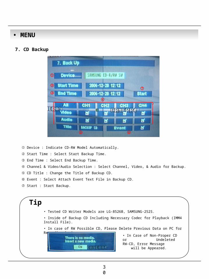
7. CD Backup
① Device : Indicate CD-RW Model Automatically.
② Start Time : Select Start Backup Time.
③ End Time : Select End Backup Time.
④ Channel & Video/Audio Selection : Select Channel, Video, & Audio for Backup.
⑤ CD Title : Change the Title of Backup CD.
⑥ Event : Select Attach Event Text File in Backup CD.
⑦ Start : Start Backup.
①
②
③⑦
④
⑤ ⑥
Tip• Tested CD Writer Models are LG-8526B, SAMSUNG-252S.
• Inside of Backup CD Including Necessary Codec for Playback (IMM4 Install File).
• In case of RW Possible CD, Please Delete Previous Data on PC for Recording Again.
• In Case of Non-Proper CD or 1 Undeleted RW-CD, Error Message 1 will be Appeared.
• MENU
30

MENU7.1 CD Backup Process
1. Choose the CD-RW at the DEVICE.2. Choose the start time and end time.3. Choose the each channel Video/Audio. If you want the Event BACK UP, Choose the event.4. Chhose the BACK UP title.(Default: “BACKUP CD”)5. Backup by Start button.
6. By User Selection Backup Time Calculation, the
Capacity of CD will be Arranged.
7. Extract Data for CD Backup.
8. Create the AVI format at the data in store.
9. Burning CD.
Tip• During CD Burning, Other Function can NOT Operated.• During CD Burning, Record Data & Remote Client Connection are Possible.
31