user's manual, sweep v0 - s3. · pdf filespecifications users manual sweep v1.0 4 ......
TRANSCRIPT

✓ Cost efficient design
✓ Operates in full sunlight
✓ Low power consumption
✓ Wide field of view
✓ Small footprint
✓ Simple serial connectivity
✓ Long Range
This device contains a component which emits laser radiation. This laser product is designated Class 1 in accordance with IEC 60825-1:2007 during all operating modes. This means that the laser is safe to look at with the unaided eye, however it is advisable to not look directly into the beam when in use.
When connecting a Sweep sensor to a 5VDC power source, it should be limited to a maximum of 8A as defined in EN 60950-1, sub clause 2.5, Table 2B.
Documentation Revision Information Rev Date Changes
0.991 07/17/2017 Added predicted life section
0.99 05/11/2017 Simplified azimuth conversion formula
0.98 04/18/2017 Updated communication protocol
0.97 03/29/2017 Updated mechanical drawings
0.9 12/19/2016 Initial Release
Laser Safety ....................................................... 0
Power Safety ..................................................... 0
Specifications ..................................................... 1
Physical ............................................................. 1
Electrical ........................................................... 1
Measurement Performance ............................. 1
Field of View ..................................................... 1
Measurement Error Test Data .......................... 1
Overview of Interfaces ....................................... 2
Connector ......................................................... 2
Status LED ......................................................... 3
Mounting Features and Orientation ................... 3
Mounting and Vibration Considerations .......... 3
Mounting Sweep with Bottom Removed ......... 3
Ingress Protection Rating .................................. 3
Enclosure Window Design ................................ 4
Theory of Operation ........................................... 4
Distance Measurement..................................... 4
Angle Measurement ......................................... 4
Predicted Life ..................................................... 4
Visualizer Overview ............................................ 4
Serial Protocol Specification ............................... 5
Data Encoding and Decoding ............................ 5
Communication Format .................................... 5
General Communication Packet Structure .......... 5
Definition of terms: ........................................... 6
DS - Start data acquisition................................. 7
DX - Stop data acquisition ................................. 8
MZ – Motor Ready ............................................ 8
MS – Adjust Motor Speed ................................. 9
MI – Motor Information ................................... 9
LR – Adjust LiDAR Sample Rate ....................... 10
LI – LiDAR Information .................................... 10
IV - Version Details .......................................... 11
ID - Device Info ................................................ 11
RR - Reset Device ............................................ 11
Appendix: ......................................................... 12
CAUTION
sweep v1.0

SPECIFICATIONS USER’S MANUAL SWEEP V1.0
1 Copyright ©2014-2017 Scanse LLC - www.scanse.io
ALL DIMENSIONS ARE IN MM, DRAWINGS ARE NOT TO SCALE
Figure 1, Sweep Dimension Drawing
Specification Value
Weight 120 g (4.23 oz.)
Operating Temperature -10 to 60° C (14 to 140°F)
Storage Temperature -40 to 80° C (-40 to 176°F)
Specification Value
Power 5VDC ±0.5VDC
Current Consumption Up to 650mA 450mA nominal
Specification Value
Range (75% reflective target)
40 m (131ft)
Resolution 1 cm (0.4 in)
Update Rate (75% reflective target)
Up to 1075Hz (see “Theory of Operation”)
Sweep is a single plane scanner. This means that as its head rotates counterclockwise, it records data in a single plane. The beam starts out at approximately 12.7mm in diameter and expands by approximately 0.5 degrees as show in Figure 2.
Figure 2, Sweep Field of View
Figure 3, Sweep Accuracy Graphs
0
10
20
30
0%
5%
10%
15%
20%
25%
30%
0 1000 2000 3000 4000
±cm
Mea
sure
men
t V
aria
bili
ty
% E
rro
r
Range in Centimeters
Long Range Error With 75% Reflective Target
0
10
20
30
0%
5%
10%
15%
20%
25%
30%
0 100 200 300 400 500 ±cm
Mea
sure
men
t V
aria
bili
ty
% E
rro
r
Range in Centimeters
Close Range Error With 75% Reflective Target
Specification Value
Horizontal Field of View 360 degrees
Vertical Field of View 0.5 degrees

SPECIFICATIONS USER’S MANUAL SWEEP V1.0
2 Copyright ©2014-2017 Scanse LLC - www.scanse.io
Sweep can be connected to low level micro controllers directly using its serial port, or to a PC using the provided USB to serial converter.
Figure 4, Sweep Cable Diagram
Sweep has two serial port connectors with identical signals. This allows for more mounting options.
DRAWINGS ARE NOT TO SCALE
Figure 5, Sweep Connector Diagram
Figure 6, Sweep Pigtail Cable Connector Detail
Table 1, Pin Definition
Pin Color Function
1 Red 5VDC ±0.5VDC
2 Orange Power enable (internal pull-up). Pull down to put device in sleep mode.
3 Yellow Sync/Device Ready Goes high when first range measurement of new scan is completed, then goes low when second range measurement is completed. Remains low until next rotation. Line is only active when scanning and low when not.
4 Green UART RX 3.3V (5V compatible)
5 Blue UART TX 3.3V (5V compatible)
6 Black Ground (-)
You can create your own cable if needed for your application. These components are readily available:
Part Description Mfg. Part No.
Connector Housing
6-Position, rectangular housing, latch-lock connector receptacle with 1.25 mm (0.049 in.) pitch.
JST GHR-06V-S
Connector terminal
26-30 AWG crimp socket connector
JST SSHL-002T-P0.2
Wire UL 1061 26 AWG stranded copper
N/A N/A

SPECIFICATIONS USER’S MANUAL SWEEP V1.0
3 Copyright ©2014-2017 Scanse LLC - www.scanse.io
The status LED (Light Emitting Diode) located on the base of the sensor can give valuable feedback.
Display Meaning
Blinking Green
Initial startup routine. No data is output at this time.
Solid Blue Normal operation.
Solid Red Internal communication error.
Figure 7, Status LED Location
Sweep has four brass threaded inserts designed to fit M2.5X0.45 screws in its base. These threaded holes are the way to mount Sweep to your device. The threaded holes are aligned with the scanner’s measurement angles. The scanner’s zero-degree measurement starting angle is aligned with the status LED, as shown in Figure 8.
Sweep can be mounted in any orientation. Sweep’s rotating head is dynamically balanced, which means it is immune to linear vibration, but it can be affected by rotational vibration. Sudden rotational shocks can cause the head to either slow down or speed up, which can affect angular measurements. If Sweep is rotationally jerked hard enough, it can cause the motor to lose sync, which will trigger a momentary motor pause, and then restart.
If space is limited, the scanner’s plastic bottom piece can be removed, and the internal motor mounting holes can be used to mount the device instead, as shown in Figure 9. Room must be provided for airflow around the scanner’s head, and care must be taken not to damage the delicate circuit board components. Using the scanner in this configuration should only be considered by professionals. A 3D model that makes these mounting dimensions clear can be found on our downloads page.
Sweep is rated as IP51, which is to say, it is not dust or water tight. It is recommended that Sweep be placed inside a protective transparent enclosure if it will be used in dusty or wet environments.
Figure 8, Sweep Standard Mounting Features
Figure 9, Sweep Internal Mounting Features
ALL DIMENSIONS ARE IN MM, DRAWINGS ARE NOT TO SCALE
SPECIFICATIONS USER’S MANUAL SWEEP V1.0
4 Copyright ©2014-2017 Scanse LLC - www.scanse.io
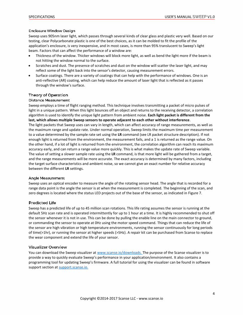
Sweep uses 905nm laser light, which passes through several kinds of clear glass and plastic very well. Based on our testing, clear Polycarbonate plastic is one of the best choices, as it can be molded to fit the profile of the application’s enclosure, is very inexpensive, and in most cases, is more than 95% translucent to Sweep’s light beam. Factors that can affect the performance of a window are:
• Thickness of the window. Thicker windows will block more light, as well as bend the light more if the beam is not hitting the window normal to the surface.
• Scratches and dust. The presence of scratches and dust on the window will scatter the laser light, and may reflect some of the light back into the sensor’s detector, causing measurement errors.
• Surface coatings. There are a variety of coatings that can help with the performance of windows. One is an anti-reflective (AR) coating, which can help reduce the amount of laser light that is reflected as it passes through the window’s surface.
Sweep employs a time of flight ranging method. This technique involves transmitting a packet of micro pulses of light in a unique pattern. When this light bounces off an object and returns to the receiving detector, a correlation algorithm is used to identify the unique light pattern from ambient noise. Each light packet is different from the last, which allows multiple Sweep sensors to operate adjacent to each other without interference. The light packets that Sweep uses can vary in length, which can affect accuracy of range measurements, as well as the maximum range and update rate. Under normal operation, Sweep limits the maximum time per measurement to a value determined by the sample rate set using the LR command (see LR packet structure description). If not enough light is returned from the environment, the measurement fails, and a 1 is returned as the range value. On the other hand, if a lot of light is returned from the environment, the correlation algorithm can reach its maximum accuracy early, and can return a range value more quickly. This is what makes the update rate of Sweep variable. The value of setting a slower sample rate using the LR command, is that more light will be gathered from a target, and the range measurements will be more accurate. The exact accuracy is determined by many factors, including the target surface characteristics and ambient noise, so we cannot give an exact number for relative accuracy between the different LR settings.
Sweep uses an optical encoder to measure the angle of the rotating sensor head. The angle that is recorded for a range data point is the angle the sensor is at when the measurement is completed. The beginning of the scan, and zero degrees is located where the status LED projects out of the base of the sensor, as indicated in Figure 7.
Sweep has a predicted life of up to 45 million scan rotations. This life rating assumes the sensor is running at the default 5Hz scan rate and is operated intermittently for up to 1 hour at a time. It is highly recommended to shut off the sensor whenever it is not in use. This can be done by pulling the enable line on the main connector to ground, or commanding the sensor to operate at 0Hz using the motor speed command. Things that can reduce the life of the sensor are high vibration or high temperature environments, running the sensor continuously for long periods of time(>1hr), or running the sensor at higher speeds (>5Hz). A repair kit can be purchased from Scanse to replace the wear component and extend the life of your sensor.
You can download the Sweep visualizer at www.scanse.io/downloads. The purpose of the Scanse visualizer is to provide a way to quickly evaluate Sweep’s performance in your application/environment. It also contains a programming tool for updating Sweep’s firmware. A full tutorial for using the visualizer can be found in software support section at support.scanse.io.
SERIAL PROTOCOL USER’S MANUAL SWEEP V1.0
5 Copyright ©2014-2017 Scanse LLC - www.scanse.io
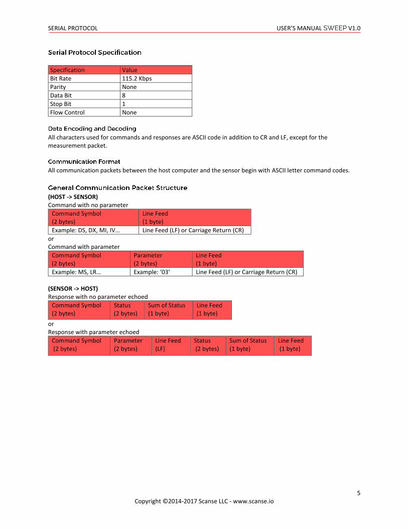
Specification Value
Bit Rate 115.2 Kbps
Parity None
Data Bit 8
Stop Bit 1
Flow Control None
All characters used for commands and responses are ASCII code in addition to CR and LF, except for the measurement packet.
All communication packets between the host computer and the sensor begin with ASCII letter command codes.
(HOST -> SENSOR) Command with no parameter
Command Symbol (2 bytes)
Line Feed (1 byte)
Example: DS, DX, MI, IV… Line Feed (LF) or Carriage Return (CR)
or Command with parameter
Command Symbol (2 bytes)
Parameter (2 bytes)
Line Feed (1 byte)
Example: MS, LR… Example: ‘03’ Line Feed (LF) or Carriage Return (CR)
(SENSOR -> HOST) Response with no parameter echoed
Command Symbol (2 bytes)
Status (2 bytes)
Sum of Status (1 byte)
Line Feed (1 byte)
or Response with parameter echoed
Command Symbol (2 bytes)
Parameter (2 bytes)
Line Feed (LF)
Status (2 bytes)
Sum of Status (1 byte)
Line Feed (1 byte)

SERIAL PROTOCOL USER’S MANUAL SWEEP V1.0
6 Copyright ©2014-2017 Scanse LLC - www.scanse.io
Command Symbol: 2 byte code at the beginning of every command (ASCII)
Parameter: Information that is needed to change sensor settings (ASCII).. Example: a motor speed code 05 transmitted as ASCII parameter '05', which has byte values [48, 53] in decimal. Line Feed (LF) or Carriage Return (CR): Terminating code. Command can have LF or CR or both as termination code but receipt will always have LF as its termination code. Status: 2 bytes of data used to convey the normal/abnormal processing of a command. ASCII byte values of '00' or '99' indicate that the sensor received and processed the command normally. Value of '11' specifies an invalid parameter was included in the command. Any other byte values are reserved for communicating other errors or failure that are command specific. Usually these indicate a failure to process the command, often for valid reasons. Sum of Status: 1 byte of data used to check for corrupted transmission. See Appendix for instructions for authenticating receipts.
ASCII Code (2 bytes) Function
DS Start data acquisition
DX Stop data acquisition
MZ Motor Ready
MS Adjust Motor Speed
MI Motor Speed Info
LR Adjust LiDAR Sample Rate
LI LiDAR Sample Rate Info
IV Version Info
ID Device Info
RR Reset Device

SERIAL PROTOCOL USER’S MANUAL SWEEP V1.0
7 Copyright ©2014-2017 Scanse LLC - www.scanse.io
• Initiates scanning
• Sensor responds with header containing status.
• Sensor begins sending constant stream of Data Block receipts, each containing a single sensor readings. This stream continues indefinitely until the host sends a DX command.
(HOST -> SENSOR)
D S LF
(SENSOR -> HOST) Header response
D S Status (2 bytes) SUM (1 byte) LF
The DS command is not guaranteed to succeed. There are a few conditions where it will fail. In the event of a failure, the two status bytes are used to communicate the failure. Status Code (2 byte ASCII code):
• ‘00’: Successfully processed command. Data acquisition effectively initiated
• ‘12’: Failed to process command. Motor speed has not yet stabilized. Data acquisition NOT initiated. Wait until motor speed has stabilized before trying again.
• ‘13’: Failed to process command. Motor is currently stationary (0Hz). Data acquisition NOT initiated. Adjust motor speed before trying again.
(SENSOR -> HOST) Data Block (7 bytes) Data Block
Sync/Error (1 byte)
Azimuth - degrees(float) (2 bytes)
Distance - cm(int) (2 bytes)
Signal Strength (1 byte)
Checksum (1 byte)
Data Block Structure: The Data Block receipt is 7 bytes long and contains all the information about a single sensor reading.
• Sync/Error Byte: The sync/error byte is multi-purpose, and encodes information about the rotation of the Sweep sensor, as well as any error information. Consider the individuals bits:
e6 e5 e4 e3 e2 e1 e0 sync
o Sync bit: least significant bit (LSB) which carries the sync value. A value of 1 indicates that this Data Block is the first acquired sensor reading since the sensor passed the 0 degree mark. Value of 0 indicates all other measurement packets.
o Error bits: 7 most significant bits (e0-6) are reserved for error encoding. The bit e0 indicates a communication error with the LiDAR module with the value 1. Bits e1:6 are reserved for future use.
• Azimuth: Angle that ranging was recorded at (in degrees). Azimuth is transmitted as a 16 bit fixed point value with a scaling factor of 16 (4bit after radix). Note: the lower order byte is received first, higher order byte is received second. Use instructions in the Appendix.
• Distance: Distance of range measurement (in cm). Distance is a 16 bit integer value. Note: the lower order byte is received first, higher order byte is received second. Use instructions in the Appendix.
• Signal strength : Signal strength of current ranging measurement. Larger is better. 8-bit unsigned int, range: 0-255
• Checksum: Calculated by adding the 6 bytes of data then dividing by 255 and keeping the remainder. (Sum of bytes 0-5) % 255 ... Use the instructions in the Appendix.

SERIAL PROTOCOL USER’S MANUAL SWEEP V1.0
8 Copyright ©2014-2017 Scanse LLC - www.scanse.io
Stops outputting measurement data. (HOST -> SENSOR)
D X LF
(SENSOR -> HOST)
D X Status (2 bytes)
SUM LF
Returns a ready code representing whether or not the device is ready. A device is ready when the calibration routine is complete, and that the motor speed has stabilized to its current setting. Intended use involves checking whether device is ready before sending a “DS” or “MS” command. (HOST -> SENSOR)
M Z LF
(SENSOR -> HOST)
M Z Ready Code (2 bytes)
LF
Ready Code (2 byte ASCII code, ie: '01' = 0x3031):
• '00' : Device is ready
• '01' : Device is NOT ready Whenever Sweep changes motor speed, it performs a calibration routine to account for inconsistencies in encoder which helps the sweep produce accurate measurements. This calibration routine is initiated after:
• powering on the device
• after receiving any form of "Adjust Motor Speed - MS" command, regardless of the size of the adjustment (ie: even calling "MS" with the current motor speed will still trigger a calibration)
During this calibration routine, the LED on the face of the device will blink blue. Once the blue LED has stopped blinking, the calibration routine is complete and the motor is ready. This wait time also helps enforce that the motor speed has stabilized at the new setting before anything else. Currently, the device cannot process certain types of commands while the calibration routine is underway. These types of commands include:
• Data Start - DS
• Adjust Motor Speed - MS The MZ command allows the user to repeatedly query the motor speed state until the return code indicates the motor speed has stabilized. After the motor speed is noted as stable, the user can safely send commands like DS or MS.

SERIAL PROTOCOL USER’S MANUAL SWEEP V1.0
9 Copyright ©2014-2017 Scanse LLC - www.scanse.io
Adjusts motor speed setting to the specified code indicating a motor speed between 0Hz and 10Hz. This sets the target speed setting, but the motor will take time (~6 seconds) to perform a calibration routine and stabilize to the new speed setting. The blue LED on the device will flash until the calibration is complete and the motor speed has stabilized. Once a speed is set, the sensor will always return to this speed, even after a power cycle (except when setting the speed to 0Hz – in which case it will go back to 5Hz after a power cycle). (HOST -> SENSOR)
M S Speed Code (2 bytes)
LF
(SENSOR -> HOST)
M S Speed Code (2 bytes)
LF Status (2 bytes)
Sum LF
Speed Code (2 byte ASCII code, ie: ‘05’ = 0x3035):
• ‘00’ = 0Hz
• ‘01’ = 1Hz
• ‘02’ = 2Hz
• ‘03’ = 3Hz
• ‘04’ = 4Hz
• ‘05’ = 5Hz
• ‘06’ = 6Hz
• ‘07’ = 7Hz
• ‘08’ = 8Hz
• ‘09’ = 9Hz
• ‘10’ = 10Hz MS command is not guaranteed to succeed. There are a few conditions where it will fail. In the event of a failure, the two status bytes are used to communicate the failure. Status Code (2 byte ASCII code, ie: ‘11’ = 0x3131):
• ‘00’: Successfully processed command. Motor speed setting effectively changed to new value. Device still requires time to stabilize, and calibrate.
• ‘11’: Failed to process command. The command was sent with an invalid parameter. Use a valid parameter when trying again.
• ‘12’: Failed to process command. Motor speed has not yet stabilized to the previous setting. Motor speed setting NOT changed to new value. Wait until motor speed has stabilized before trying to adjust it again.
Returns current motor speed code representing the rotation frequency (in Hz) of the current target motor speed setting. This does not mean that the motor speed is stabilized yet. (HOST -> SENSOR)
M I LF
(SENSOR -> HOST)
M I Speed Code (2 bytes)
LF
See previous “MS – Adjust Motor Speed” command for a breakdown of the possible Speed Codes.
SERIAL PROTOCOL USER’S MANUAL SWEEP V1.0
10 Copyright ©2014-2017 Scanse LLC - www.scanse.io
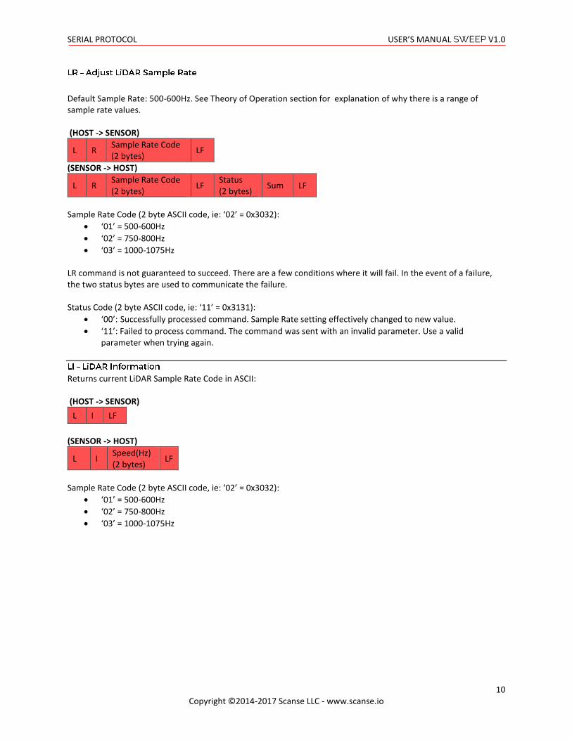
Default Sample Rate: 500-600Hz. See Theory of Operation section for explanation of why there is a range of sample rate values. (HOST -> SENSOR)
L R Sample Rate Code (2 bytes)
LF
(SENSOR -> HOST)
L R Sample Rate Code (2 bytes)
LF Status (2 bytes)
Sum LF
Sample Rate Code (2 byte ASCII code, ie: ‘02’ = 0x3032):
• ‘01’ = 500-600Hz
• ‘02’ = 750-800Hz
• ‘03’ = 1000-1075Hz LR command is not guaranteed to succeed. There are a few conditions where it will fail. In the event of a failure, the two status bytes are used to communicate the failure. Status Code (2 byte ASCII code, ie: ‘11’ = 0x3131):
• ‘00’: Successfully processed command. Sample Rate setting effectively changed to new value.
• ‘11’: Failed to process command. The command was sent with an invalid parameter. Use a valid parameter when trying again.
Returns current LiDAR Sample Rate Code in ASCII: (HOST -> SENSOR)
L I LF
(SENSOR -> HOST)
L I Speed(Hz) (2 bytes)
LF
Sample Rate Code (2 byte ASCII code, ie: ‘02’ = 0x3032):
• ‘01’ = 500-600Hz
• ‘02’ = 750-800Hz
• ‘03’ = 1000-1075Hz

SERIAL PROTOCOL USER’S MANUAL SWEEP V1.0
11 Copyright ©2014-2017 Scanse LLC - www.scanse.io
Returns details about the device's version information. • Model • Protocol Version • Firmware Version • Hardware Version • Serial Number (HOST -> SENSOR)
I V LF
(SENSOR -> HOST)
I V Model (5 bytes)
Protocol (2 bytes)
Firmware Version (2 bytes)
Hardware Version (1 byte)
Serial Number (8 bytes)
LF
Example: IVSWEEP01011100000001
I V SWEEP 01 01 1 00000001 LF
Returns details about the device's current state/settings.
• Bit Rate
• Laser State
• Mode
• Diagnostic
• Motor Speed
• Sample Rate (HOST -> SENSOR)
I D LF
(SENSOR -> HOST)
I D Bit Rate (6 bytes)
Laser state Mode Diagnostic Motor Speed (2 bytes)
Sample Rate (4 bytes)
LF
Example: IV115200110050500
I D 115200 1 1 0 05 0500 LF
Resets the device. Green LED indicates the device is resetting and cannot receive commands. When the LED turns blue, the device has successfully reset. (HOST -> SENSOR)
R R LF
(SENSOR -> HOST) No Response

APPENDIX USER’S MANUAL SWEEP V1.0
12 Copyright ©2014-2017 Scanse LLC - www.scanse.io
Authenticating Receipts (Does not apply to Data Block)
Authentication of a valid receipt is accomplished by a checksum, which uses the Status (2 bytes) and Sum of Status (1 byte) from the receipt. To perform the checksum, the received Sum of Status bytes is checked against a calculated sum of the 2 Status bytes. The protocol design allows for performing the checksum visually in a terminal, which requires all bytes in a receipt to be legible ASCII values (ex: '00P'). Therefore, performing the checksum in code is not intuitive. It works like this:
• The status bytes are summed
• The lower 6 bits (Least Significant) of that sum are then added to 30Hex
• The resultant value is compared with the checksum byte
//statusByte#1 + statusByte#2 let sumOfStatusBytes = status1_byteValue + status2_byteValue; //grab the lower (least significant) 6 bits by performing a bit-wise AND with 0x3F (ie: 00111111) let lowerSixBits = sumOfStatusBytes & 0x3F; //add 30Hex to it let sum = lowerSixBits + 0x30; return ( sum === checkSumByteValue );
Example: Consider the common case of '00P' (decimal -> [48, 48, 80], hex -> [0x30, 0x30, 0x50])
0x30 + 0x30 = 0x60 // sum of the status bytes 0x60 & 0x3F = 0x20 // retrieve only the lower 6 bits 0x20 + 0x30 = 0x50 // calculate the ASCII legible sum 0x50 = 'P' // translate to ASCII
Parsing Data Block 16-bit integers and floats
The Data Block receipt includes int-16 and fixed-point values (distance & azimuth). In the case of distance, the value is a 16-bit integer. In the case of the azimuth, the value is a fixed-point with a scaling factor of 16.
A 16-bit int is sent as two individual bytes. The lower order byte is received first, and the higher order byte is received second. For example, parsing the distance:
//assume dataBlock holds the DATA_BLOCK byte array //such that indices 3 & 4 correspond to the two distance bytes let distance = (dataBlock[4] << 8) + (dataBlock[3]); For fixed-point values (azimuth), start by using the same technique to acquire a 16-bit int. Once you have it, you can perform the conversion to fixed-point value like so:
//assume dataBlock holds the DATA_BLOCK byte array, //such that indices 1 & 2 correspond to the two azimuth bytes let angle_int = (dataBlock[2] << 8) + (dataBlock[1]); let degree = angle_int/16.0;

APPENDIX USER’S MANUAL SWEEP V1.0
13 Copyright ©2014-2017 Scanse LLC - www.scanse.io
Performing Data Block Checksum
The last byte of a Data Block receipt is a checksum byte. It represents the sum of all bytes up until the checksum byte (ie: the first 6 bytes). Obviously, a single byte caps at 255, so the checksum can't reliably hold the sum of 6 other bytes. Instead, the checksum byte uses the modulo operation and effectively contains the remainder after dividing the sum by 255 (this is the same as saying sum % 255). Validating the checksum looks like: //ONLY applies to receipts of type ReceiptEnum.DATA_BLOCK //calculate the sum of the specified status or msg bytes let calculatedSum = 0; for(let i = 0; i < 6; i++){ //add each status byte to the running sum calculatedSum += dataBlock[i]; } calculatedSum = calculatedSum % 255; let expectedSumVal = dataBlock[6]; return calculatedSum === expectedSumVal;