user's manual voltage protection relay -...
TRANSCRIPT

User's
Manual
Voltage Protection RelayUser's
Manual
Features
• Low-set undervoltage stage with definite time or inverse time• High-set undervoltage stage with definite time• Low-set overvoltage stage with definite time or inverse time• High-set overvoltage stage with definite time• Negative sequence overvoltage protection• Neutral displacement/ residual overvoltage protection• Multi-function isolated digital input• Fault data and event code recording• Five programmable voltage-free output contacts• Isolated RS485 Modbus-RTU communication
Table of Contents Page
1
For continuous product development, we reserve the right to supplyequipment which may vary from that described in this manual.
1. Introduction
2. Description of Operation
3. Display
4. Key Button Input
5. Programming
6. Soft Switches
7. Connection Diagram & Terminal Connection
8. Case Dimension
9. Technical Data
10. Test and Standards
11. Appendix A
12. Appendix B
13. Appendix C
2
3
12
22
24
27
52
58
59
61
62
63
64
2
Features
1. Introduction
The MU2300 voltage protection relay is a microprocessor basednumerical relay intended for the voltage protection in electricaldistribution network. It can also be used for generators, motors andtransformer protection.
A fully digital user interface with bright seven-segment display andindicators provides a very user friendly access to all the measurements,user parameters and records.
MU2300 uses a digital filter to extract the fundamental voltagewaveforms for the three phases, phase-to-phase voltage or phase-to-neutral voltage, for the operation of the protection elements. Suchprotection elements are undervoltage low-set and high-set; overvoltagelow-set and high-set; negative sequence overvoltage low-set; residualovervoltage low-set.
Besides being operated from the front panel of MU2300, this relay canalso be accessed when connected to a networked system through itsisolated RS485 Modbus-RTU communication interface.
• Low-set undervoltage stage with definite-time or inverse time• High-set undervoltage stage with definite-time• Low-set overvoltage stage with definite-time or inverse time• High-set overvoltage stage with definite-time• Negative sequence overvoltage protection• Neutral displacement/ residual overvoltage protection• Multi-function isolated digital input• Fault data and event code recording• Five programmable voltage-free output contacts• Isolated RS485 Modbus-RTU communication
3
2. Description of Operation
MU2300 is equipped with 3 accurate and independent voltage inputsconnected to the voltage transformers of the object to be protected. Itcontinuously monitors these voltage inputs’ fundamental frequencycomponents for the occurrence of faults. On detection of a fault, the relaywill start and then operated the trip output which is connected to thecircuit breaker or indicator. The phase-to-phase voltage, phase-to-neutralvoltage, negative sequence voltage and the residual voltage, measured atthe moment of tripping, will be recorded in the memories of the relay.
The relay has four different voltage transformer (VT) configurations.Depending on the configuration chosen, the input voltages can be phase-to-phase voltages or phase-to-neutral voltages. If the inputs are phase-to-phase voltages, the protection setting is based on the phase-to-phasevoltages. However, if the configuration chosen is for phase-to-neutralinput voltages, the protection setting will then be based on the phase-to-phase voltages and the derived phase-to-phase voltages are formeasurements only.
2.1 Undervoltage Elements (27)
The MU2300 has two stages for undervoltage protection, namely the low-set undervoltage element and high-set undervoltage element.
When the voltage values fall below the set low-set undervoltage value,the low-set undervoltage element will start and deliver a start signal to thecontact output (if assigned) and the front panel START indicator. After apre-set delay time, determined by the user’s selection between definite-time and inverse time characteristic, the undervoltage element delivers atrip signal to the contact output (if assigned) and the front panel TRIPindicator. Similarly, the high-set undervoltage element will start and thendeliver a trip signal to the contact output (if assigned) and the front panelindicators if the voltage falls below the set high-set undervoltage valuefor duration longer than the high-set definite time.
The low-set and high-set elements can be selectively blocked by thedigital input if the appropriate switch setting in Soft Switch 9A and SoftSwitch 9B are set. The high-set stage can also be set out of operation bySoft Switch 8.
4
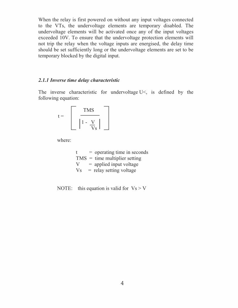
When the relay is first powered on without any input voltages connectedto the VTs, the undervoltage elements are temporary disabled. Theundervoltage elements will be activated once any of the input voltagesexceeded 10V. To ensure that the undervoltage protection elements willnot trip the relay when the voltage inputs are energised, the delay timeshould be set sufficiently long or the undervoltage elements are set to betemporary blocked by the digital input.
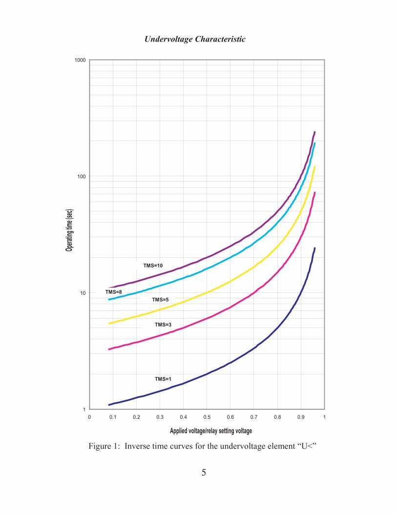
2.1.1 Inverse time delay characteristic
The inverse characteristic for undervoltage U<, is defined by thefollowing equation:
TMSt =
1 - VVs
where:
t = operating time in secondsTMS = time multiplier settingV = applied input voltageVs = relay setting voltage
NOTE: this equation is valid for Vs > V
5
1
10
100
1000
0 0.1 0.2 0.3 0.4 0.5 0.6 0.7 0.8 0.9 1
TMS=1
TMS=5
TMS=3
TMS=10
TMS=8
Applied voltage/relay setting voltage
Opera
tingt
ime(se
c)
Undervoltage Characteristic
Figure 1: Inverse time curves for the undervoltage element “U<”
6
2.2 Overvoltage Elements (59)
The MU2300 has two stages for overvoltage protection, namely the low-set overvoltage element and high-set overvoltage element.
When the voltage values rise above the set low-set overvoltage value, thelow-set overvoltage element will start and deliver a start signal to thecontact output (if assigned) and the front panel START indicator. After apre-set delay time, determined by the user’s selection between definite-time and inverse time characteristic, the overvoltage element delivers atrip signal to the contact output (if assigned) and the front panel TRIPindicator. Similarly, the high-set overvoltage element will start and thendeliver a trip signal to the contact output (if assigned) and the front panelindicators if the voltage values rise above the set high-set overvoltagevalue for duration longer than the high-set definite time.
The low-set and high-set elements can be selectively blocked by thedigital input if the appropriate switch settings in Soft Switch 9A and SoftSwitch 9B are set. The high-set stage can also be set out of operation bySoft Switch 8.
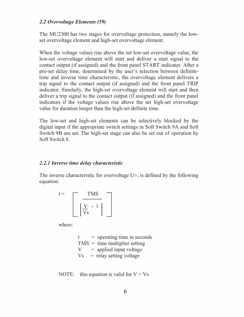
2.2.1 Inverse time delay characteristic
The inverse characteristic for overvoltage U>, is defined by the followingequation:
t = TMS
V - 1Vs
where:
t = operating time in secondsTMS = time multiplier settingV = applied input voltageVs = relay setting voltage
NOTE: this equation is valid for V > Vs
|
7
0.01
0.1
1
10
100
1000
0 2 4 6 8 10 12 14 16 18 20
Applied voltage input/relay setting voltage
Op
erat
ing
tim
e(s
ec)
TMS=1
TMS=8
TMS=10
TMS=5
TMS=3
Overvoltage Characteristic
Figure 2: Inverse time curves for the overvoltage element “U>”

8
2.3 Negative Sequence Overvoltage Element (47)
For negative sequence overvoltage on MU2300, there is only low-setelement. The negative sequence voltage is derived from the three phase-to-neutral voltages measured from the voltage inputs if the relay isconfigured in Soft Switch A to measure the phase-to-neutral voltages. Ifthe relay is configured in Soft Switch A to measure the phase-to-phasevoltages, the negative sequence voltage is derived from the phase-to-phase voltage.
When the negative sequence voltage value rises above the set low-setnegative sequence value, the negative sequence low-set overvoltageelement will start and deliver a start signal to the contact output (ifassigned) and the front panel START indicator. After a pre-set delay timedetermined by the user’s selection between definite-time and inverse timethe negative sequence overvoltage element delivers a trip signal to thecontact output (if assigned) and the front panel TRIP indicator.
The low-set element can be selectively blocked by the digital input if theappropriate switch settings in Soft Switch 9A and Soft Switch 9B are setaccordingly.
2.3.1 Inverse time delay characteristic
The inverse characteristic for negative sequence overvoltage U2>,isdefined by the following equation:
TMSt =
V - 1Vs
where:
t = operating time in secondsTMS = time multiplier settingV = calculated negative sequence voltageVs = relay setting voltage
NOTE: this equation is valid for V > Vs
|

9
0.01
0.1
1
10
100
1000
0 2 4 6 8 10 12 14 16 18 20
Op
erat
ing
tim
e(s
ec)
TMS=1
TMS=8
TMS=10
TMS=5
TMS=3
Figure 3: Inverse time curves for the overvoltage element “U2>”
Negative sequence overvoltage characteristic
Derived negative sequence overvoltage/relay setting voltage
10
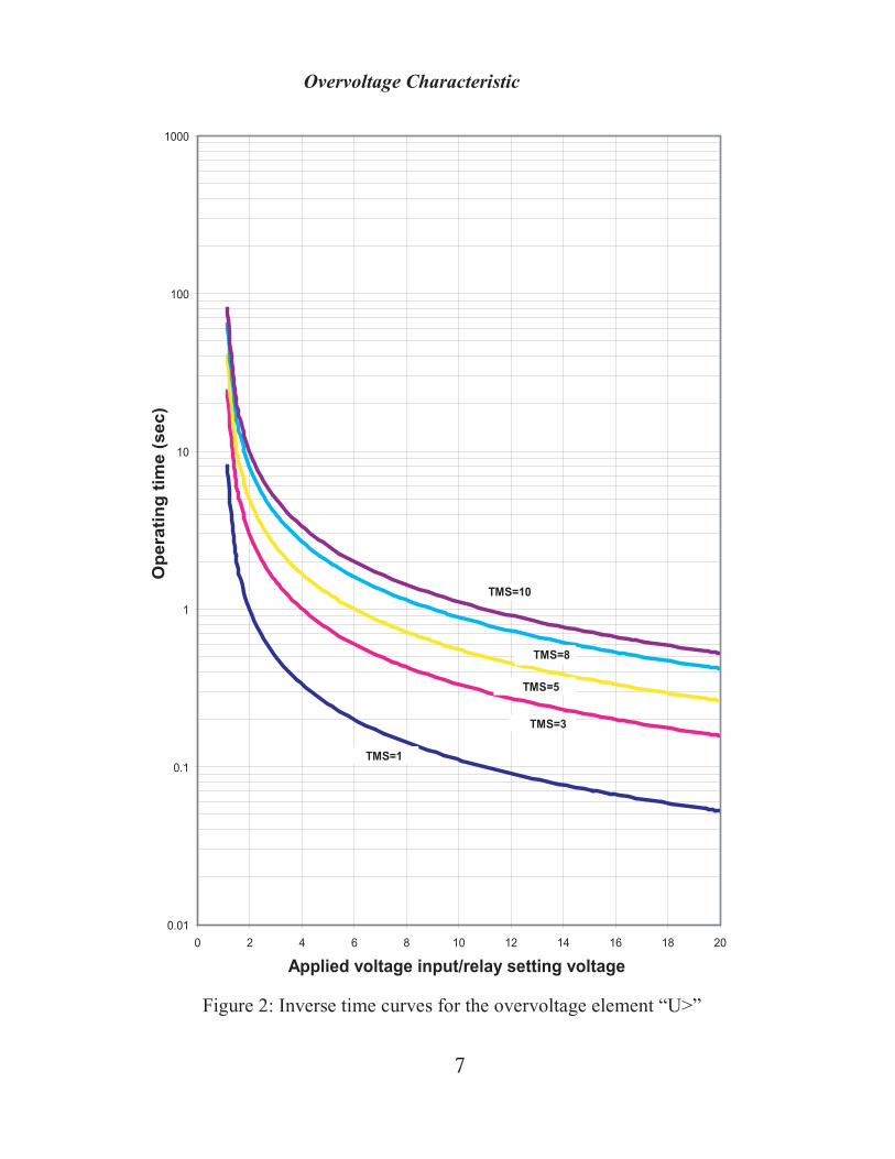
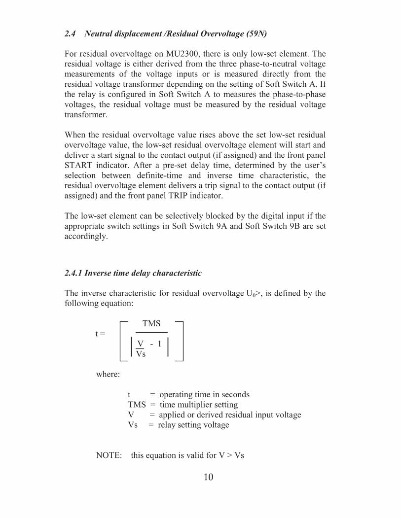
2.4.1 Inverse time delay characteristic
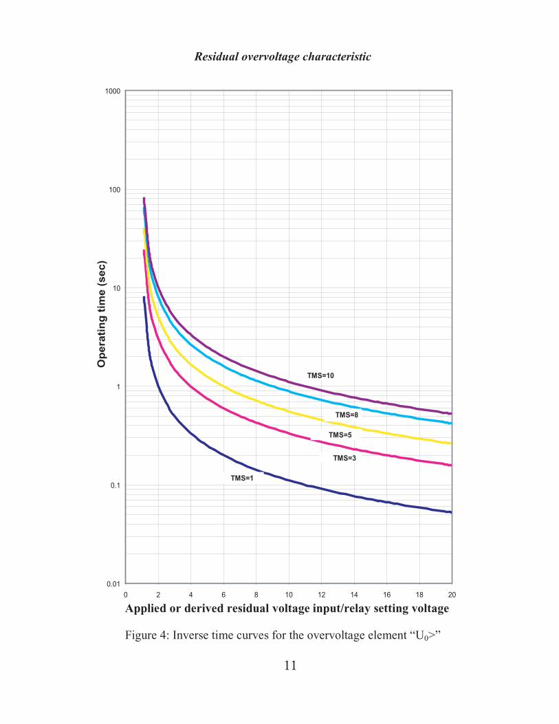
The inverse characteristic for residual overvoltage U0>, is defined by thefollowing equation:
TMSt =
V - 1Vs
where:
t = operating time in secondsTMS = time multiplier settingV = applied or derived residual input voltageVs = relay setting voltage
NOTE: this equation is valid for V > Vs
2.4 Neutral displacement /Residual Overvoltage (59N)
For residual overvoltage on MU2300, there is only low-set element. Theresidual voltage is either derived from the three phase-to-neutral voltagemeasurements of the voltage inputs or is measured directly from theresidual voltage transformer depending on the setting of Soft Switch A. Ifthe relay is configured in Soft Switch A to measures the phase-to-phasevoltages, the residual voltage must be measured by the residual voltagetransformer.
When the residual overvoltage value rises above the set low-set residualovervoltage value, the low-set residual overvoltage element will start anddeliver a start signal to the contact output (if assigned) and the front panelSTART indicator. After a pre-set delay time, determined by the user’sselection between definite-time and inverse time characteristic, theresidual overvoltage element delivers a trip signal to the contact output (ifassigned) and the front panel TRIP indicator.
The low-set element can be selectively blocked by the digital input if theappropriate switch settings in Soft Switch 9A and Soft Switch 9B are setaccordingly.
11
0.01
0.1
1
10
100
1000
0 2 4 6 8 10 12 14 16 18 20
Op
erat
ing
tim
e(s
ec)
TMS=1
TMS=8
TMS=10
TMS=5
TMS=3
Figure 4: Inverse time curves for the overvoltage element “U0>”
Residual overvoltage characteristic
Applied or derived residual voltage input/relay setting voltage
12
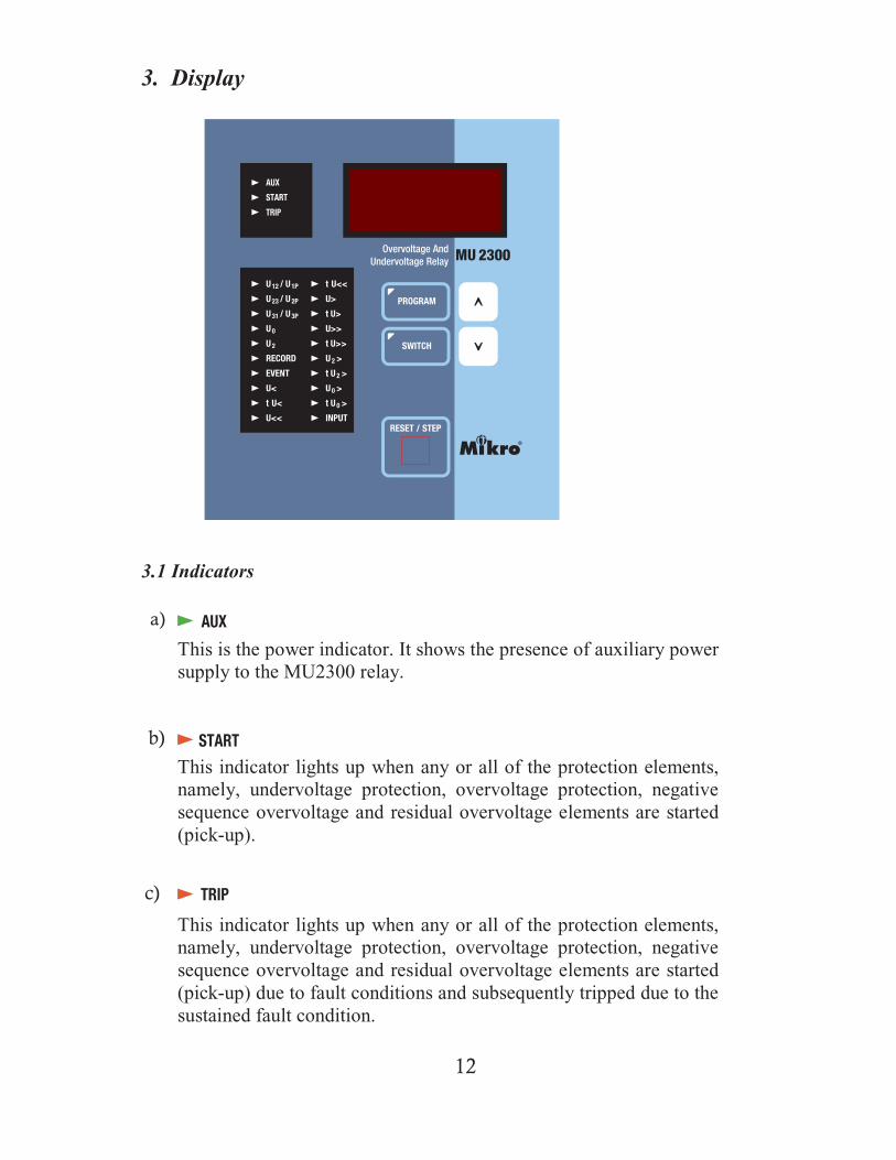
3. Display
a)
b)
c)
3.1 Indicators
This is the power indicator. It shows the presence of auxiliary powersupply to the MU2300 relay.
This indicator lights up when any or all of the protection elements,namely, undervoltage protection, overvoltage protection, negativesequence overvoltage and residual overvoltage elements are started(pick-up).
This indicator lights up when any or all of the protection elements,namely, undervoltage protection, overvoltage protection, negativesequence overvoltage and residual overvoltage elements are started(pick-up) due to fault conditions and subsequently tripped due to thesustained fault condition.
13
e)
Number Value
Number Value
U12/ U1P
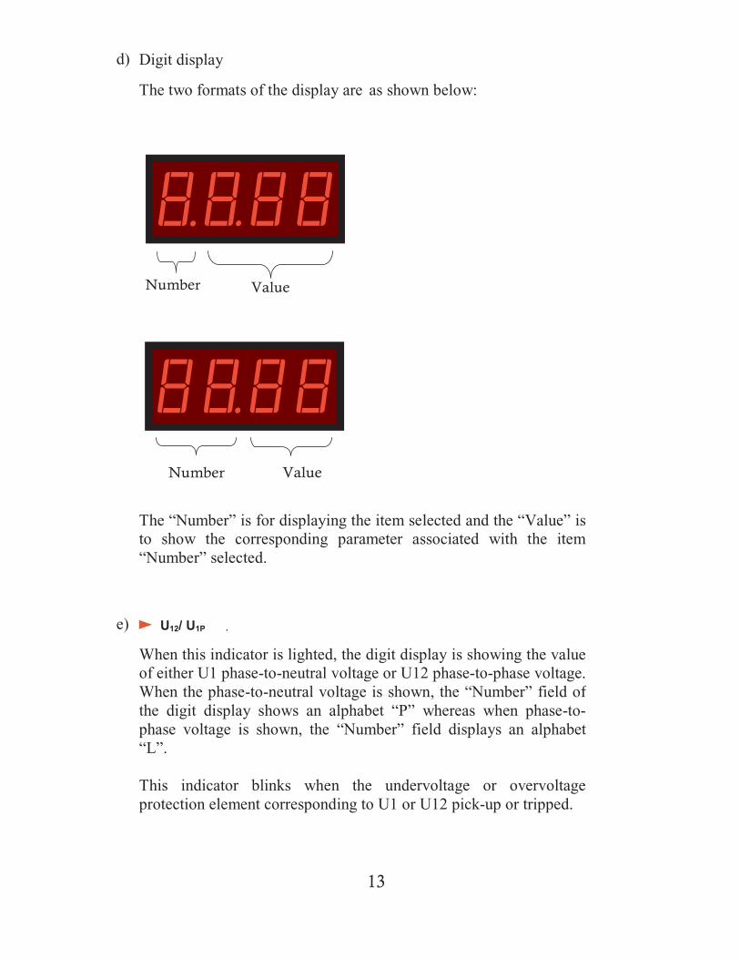
d) Digit display
The two formats of the display are as shown below:
The “Number” is for displaying the item selected and the “Value” isto show the corresponding parameter associated with the item“Number” selected.
When this indicator is lighted, the digit display is showing the valueof either U1 phase-to-neutral voltage or U12 phase-to-phase voltage.When the phase-to-neutral voltage is shown, the “Number” field ofthe digit display shows an alphabet “P” whereas when phase-to-phase voltage is shown, the “Number” field displays an alphabet“L”.
This indicator blinks when the undervoltage or overvoltageprotection element corresponding to U1 or U12 pick-up or tripped.

14
f)
g)
h)
i)
j)
k)
U23/U2P
U31/U3P
U0
U2
Record
Event
Similar to item e) above, this indicator shows the U2 phase-to-neutral voltage or U23 phase-to-phase voltage.
Similar to item e) above, this indicator shows the U3 phase-to-neutral voltage or U31 phase-to-phase voltage.
When this indicator is lighted, the digit display shows the residualvoltage. It blinks when the corresponding protection element pick-up or trip.
When this indicator is lighted, the digit display shows the negativesequence voltage. It blinks when the corresponding protectionelement pick-up or trip.
This indicator will light up simultaneously with either U12/U1P,U23/U2P, U31/U3P, U0, or U2. When lighted, the digit display isshowing the previously recorded voltages at then moment whenMU2300 trips. There are nine records available and each can beviewed at by pressing the DOWN key. Record number 1 is the latestrecord.
When this indicator is lighted, the digit display is showing therecorded event code. There are 60 numbers of events available and
15
l)
m)
n)
o)
U<
tU<
U<<
tU<<
all the recorded events will be cleared when the auxiliary powersupply to MU2300 is disconnected. The event code is in AppendixC.
All event registered will be displayed one-by-one automatically ifthe relay is left untouched in this mode of for about 20 seconds.
When this indicator is lighted, the digit display shows the low-setundervoltage setting. The “Number” field of the digit displayindicates whether it is a Group A or Group B setting. The “Value”field shows the setting voltage.
When this indicator is lighted, depending on the user setting on SoftSwitch 7, the digit display will either show the TMS or the definitetime delay for low-set undervoltage. The “Number” field of the digitdisplay shows whether it is a Group A or Group B setting.
When this indicator is lighted, the digit display shows the high-setundervoltage setting. The “Number” field of the digit displayindicates whether it is a Group A or Group B setting. The “Value”field shows the setting voltage.
When this indicator is lighted, the digit display shows the high-setdefinite time delay for undervoltage. The “Number” field of thedigit display shows whether it is a Group A or Group B setting.

16
p)
q)
r)
U>
tU>
U>>
tU>>
U2>
s)
t)
When this indicator is lighted, the digit display shows the low-setovervoltage setting. The “Number” field of the digit displayindicates whether it is a Group A or Group B setting. The “Value”field shows the setting voltage.
When this indicator is lighted, depending on the user setting on SoftSwitch 7, the digit display will either show the TMS or the definitetime delay for low-set overvoltage. The “Number” field of the digitdisplay shows whether it is a Group A or Group B setting.
When this indicator is lighted, the digit display shows the high-setovervoltage setting. The “Number” field of the digit displayindicates whether it is a Group A or Group B setting. The “Value”field shows the setting voltage.
When this indicator is lighted, the digit display shows the high-setdefinite time delay for overvoltage. The “Number” field of the digitdisplay shows whether it is a Group A or Group B setting.
When this indicator is lighted, the digit display shows the low-setnegative sequence overvoltage setting. The “Number” field of thedigit display indicates whether it is a Group A or Group B setting.The “Value” field shows the setting for the negative sequenceovervoltage.
17
tU2>
U0>
tU0>
INPUT
u)
v)
w)
x)
When this indicator is lighted, depending on the user setting on SoftSwitch 7, the digit display will either show the TMS multiplier orthe definite time delay for low-set negative sequence overvoltage.The “Number” field of the digit display shows whether it is a GroupA or Group B setting.
When this indicator is lighted, the digit display shows the low-setresidual overvoltage setting. The “Number” field of the digit displayindicates whether it is a Group A or Group B setting. The “Value”field shows the setting for the residual overvoltage.
When this indicator is lighted, depending on the user setting on SoftSwitch 7, the digit display will either show the TMS or the definitetime delay for low-set residual overvoltage. The “Number” field ofthe digit display shows whether it is a Group A or Group B setting.
This indicator reflects the status of the external digital inputregardless of the soft switches setting. It is a direct mimic of thestatus of the input. When voltage is applied to the digital input, theindicator will turn on.
18
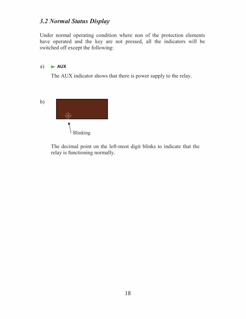
3.2 Normal Status Display
Under normal operating condition where non of the protection elementshave operated and the key are not pressed, all the indicators will beswitched off except the following:
a)
The AUX indicator shows that there is power supply to the relay.
b)
AUX
Blinking
The decimal point on the left-most digit blinks to indicate that therelay is functioning normally.

19
3.3 Start Status Display
The Start indicator lights up when any of the protection elements pick-up(started). Other indicators also lighted simultaneously to show whichprotection elements have started.
START
U12/U1P
U23/U2P
U31/U3P
a) The Start indicator light up to indicate that the relay pick up.
b) One or more of the following indicators blink to indicate the sourcesof the pick-up.
U0
U2
U<
U<<
U>
U>>
U2>
U0>
c) One or more of the following indicators blink to indicate that theprotection elements that have pick-up.

20
TRIP
U12/U1P
U23/U2P
3.4 Trip Status Display
The Trip indicator lights up when any of the protection elements trip.Other indicators also lighted simultaneously to show which protectionelements have tripped.
a) The Trip indicator light up to indicates that the relay has tripped. Itstays steady when the condition for tripping has not been removed.Otherwise, the indicator blinks.
b) One of the following indicators blink to indicate the sources of thepick-up.
U31/U3P
U0
U2
U<
U<<
U>
U>>
U2>
U0>
c) One of the following indicators blink to indicate that the protectionelements that have pick-up.
21
Number Value
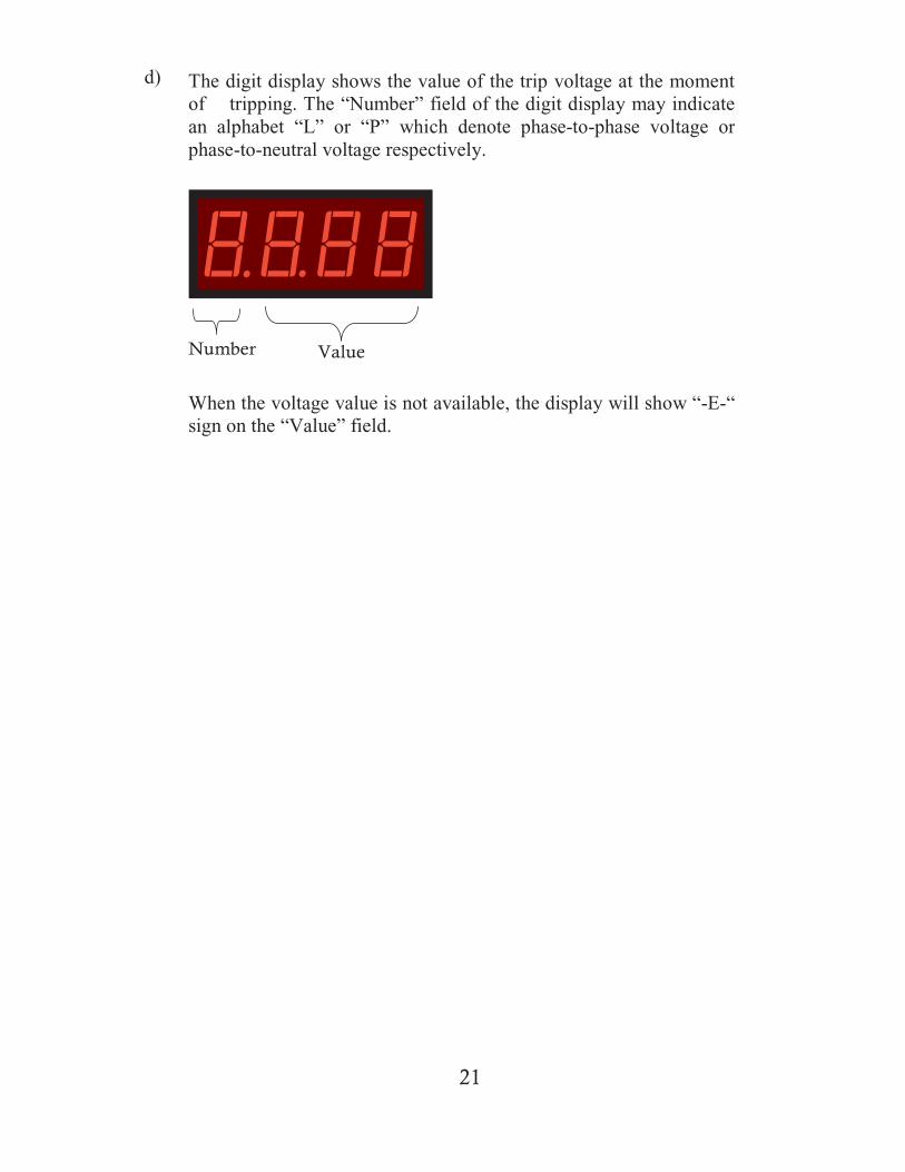
d) The digit display shows the value of the trip voltage at the momentof tripping. The “Number” field of the digit display may indicatean alphabet “L” or “P” which denote phase-to-phase voltage orphase-to-neutral voltage respectively.
When the voltage value is not available, the display will show “-E-“sign on the “Value” field.
22
START
U12
U1P
U23
U2P
U31
U3P
U0
U2
U12/U1P Record
U23/U2P Record
U31/U3P Record
U0 Record U<
tU<
U<<
tU<<
U>
tU>
U>>
tU>>
U2>
tU2>
U0>
U2 Record Event
tU0>
Other U12/U1P Record
Other U23/U2P Record
Other U31/U3P Record
Other U0 Record
Other U2 Record
*
*
*
*
*
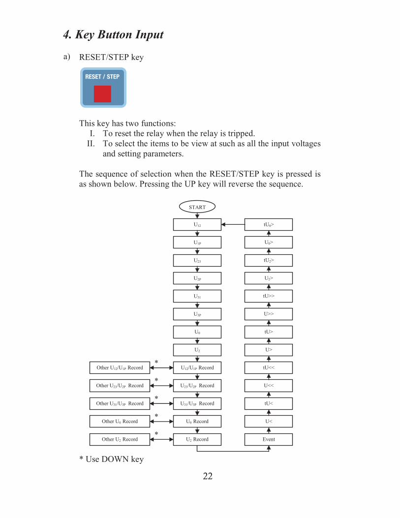
* Use DOWN key
4. Key Button Input
a) RESET/STEP key
This key has two functions:I. To reset the relay when the relay is tripped.
II. To select the items to be view at such as all the input voltagesand setting parameters.
The sequence of selection when the RESET/STEP key is pressed isas shown below. Pressing the UP key will reverse the sequence.

23
b) The PROGRAM key
Item to be programmed is first selected by the RESET/STEP key.Then pressing the PROGRAM key set the relay into programmingmode for the selected item. Value of the selected item can then bechanged by the UP or DOWN key. Pressing the PROGRAM keyagain while in the programming mode will cause the relay to exitfrom the programming mode with the new value saved into the non-volatile memory.
The indicator adjacent to the PROGRAM key will light up when inprogramming mode.
c) The UP and DOWN keys
These keys are for changing the value of the selected item while inprogramming mode. Under non-programming mode, the UP key isused as the reverse STEP key and the DOWN key is used forchanging the record number while in the recorded data retrievalmode.
d) The SWITCH key
Press this key to step through all the soft switches.
24
5. Programming
5.1 To program the setting for U <, U <<, U >, U >>, U0 >,and U2 >
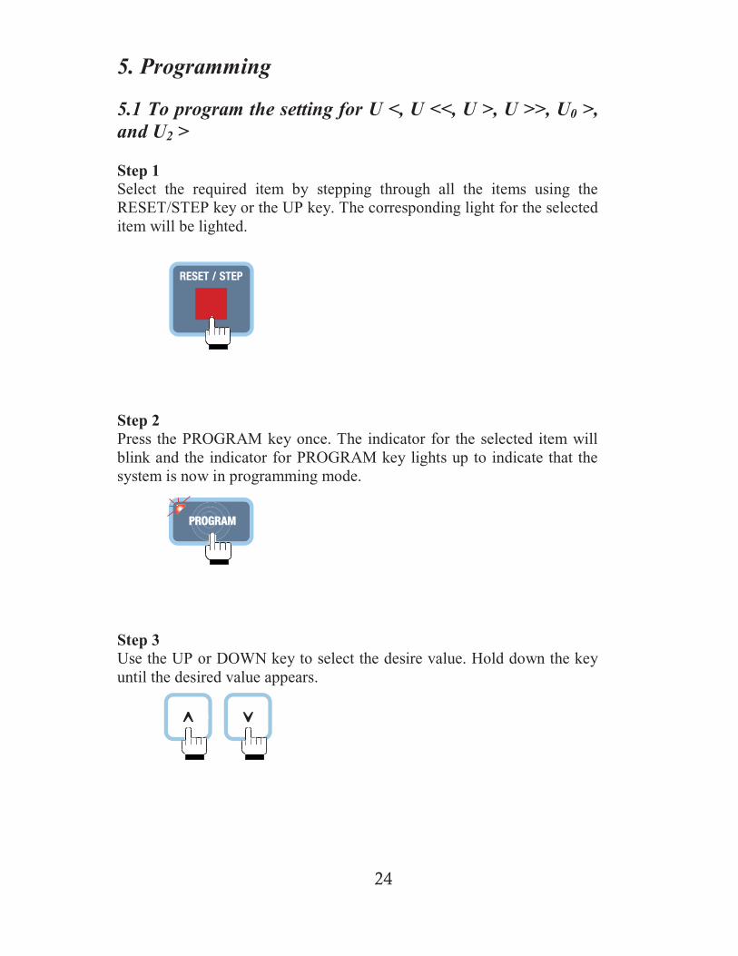
Step 1Select the required item by stepping through all the items using theRESET/STEP key or the UP key. The corresponding light for the selecteditem will be lighted.
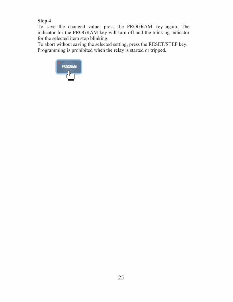
Step 2Press the PROGRAM key once. The indicator for the selected item willblink and the indicator for PROGRAM key lights up to indicate that thesystem is now in programming mode.
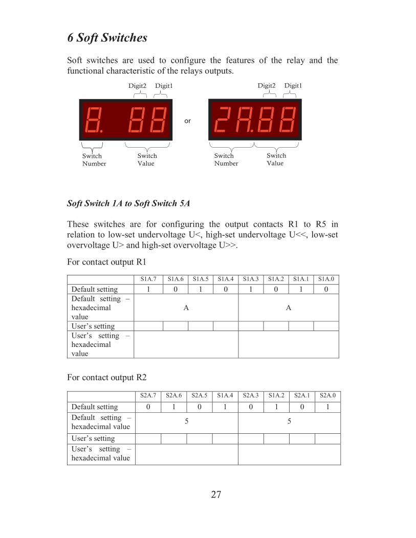
Step 3Use the UP or DOWN key to select the desire value. Hold down the keyuntil the desired value appears.
25
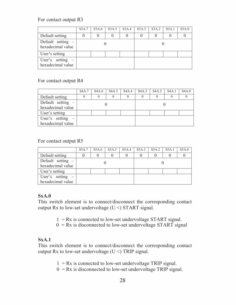
Step 4To save the changed value, press the PROGRAM key again. Theindicator for the PROGRAM key will turn off and the blinking indicatorfor the selected item stop blinking.To abort without saving the selected setting, press the RESET/STEP key.Programming is prohibited when the relay is started or tripped.

26
5.2 To program the soft switches
Step1Press the SWITCH key until the desired switch number appears on thedisplay.
Step 2Press the PROGRAM key to enter into programming mode. The switchnumber on the “Number” field of the digit display blinks to indicate thatthe system is now in soft switch programming mode. The indicators forthe PROGRAM and the SWITCH keys also light up.
Step 3Use the UP or DOWN key for changing the soft switch setting. Holddown the key until the desired value appears.
Step 4Press the PROGRAM key again to save the changed setting. The switchnumber will stop blinking and the indicator for the PROGRAM key willbe switched off.
To abort without saving the change, press the SWITCH key or RESET/STEP key. Programming is prohibited when the relay is started or tripped.
27
SwitchNumber
SwitchValue
Digit2 Digit1
For contact output R1
6 Soft Switches
Soft switches are used to configure the features of the relay and thefunctional characteristic of the relays outputs.
S1A.7 S1A.6 S1A.5 S1A.4 S1A.3 S1A.2 S1A.1 S1A.0
Default setting 1 0 1 0 1 0 1 0Default setting –hexadecimalvalue
A A
User’s settingUser’s setting –hexadecimalvalue
SwitchNumber
SwitchValue
Digit2 Digit1
or
For contact output R2
S2A.7 S2A.6 S2A.5 S1A.4 S2A.3 S1A.2 S2A.1 S2A.0
Default setting 0 1 0 1 0 1 0 1Default setting –hexadecimal value
5 5
User’s settingUser’s setting –hexadecimal value
Soft Switch 1A to Soft Switch 5A
These switches are for configuring the output contacts R1 to R5 inrelation to low-set undervoltage U<, high-set undervoltage U<<, low-setovervoltage U> and high-set overvoltage U>>.
28
For contact output R3
For contact output R4
For contact output R5
S3A.7 S3A.6 S3A.5 S3A.4 S3A.3 S3A.2 S3A.1 S3A.0
Default setting 0 0 0 0 0 0 0 0Default setting –hexadecimal value
0 0
User’s settingUser’s setting –hexadecimal value
S4A.7 S4A.6 S4A.5 S4A.4 S4A.3 S4A.2 S4A.1 S4A.0
Default setting 0 0 0 0 0 0 0 0
Default setting –hexadecimal value
0 0
User’s settingUser’s setting –hexadecimal value
S5A.7 S5A.6 S5A.5 S5A.4 S5A.3 S5A.2 S5A.1 S5A.0
Default setting 0 0 0 0 0 0 0 0Default setting –hexadecimal value
0 0
User’s settingUser’s setting –hexadecimal value
SxA.0This switch element is to connect/disconnect the corresponding contactoutput Rx to low-set undervoltage (U <) START signal.
1 = Rx is connected to low-set undervoltage START signal.0 = Rx is disconnected to low-set undervoltage START signal
SxA.1This switch element is to connect/disconnect the corresponding contactoutput Rx to low-set undervoltage (U <) TRIP signal.
1 = Rx is connected to low-set undervoltage TRIP signal.0 = Rx is disconnected to low-set undervoltage TRIP signal.
29
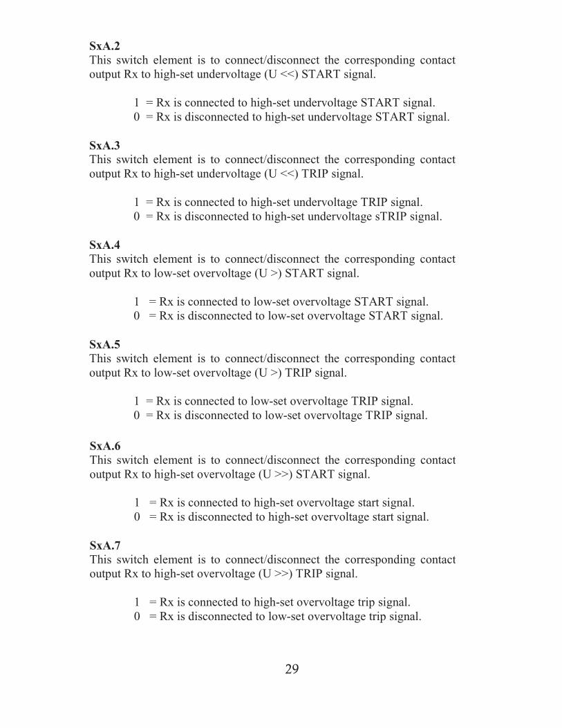
SxA.2This switch element is to connect/disconnect the corresponding contactoutput Rx to high-set undervoltage (U <<) START signal.
1 = Rx is connected to high-set undervoltage START signal.0 = Rx is disconnected to high-set undervoltage START signal.
SxA.3This switch element is to connect/disconnect the corresponding contactoutput Rx to high-set undervoltage (U <<) TRIP signal.
1 = Rx is connected to high-set undervoltage TRIP signal.0 = Rx is disconnected to high-set undervoltage sTRIP signal.
SxA.4This switch element is to connect/disconnect the corresponding contactoutput Rx to low-set overvoltage (U >) START signal.
1 = Rx is connected to low-set overvoltage START signal.0 = Rx is disconnected to low-set overvoltage START signal.
SxA.5This switch element is to connect/disconnect the corresponding contactoutput Rx to low-set overvoltage (U >) TRIP signal.
1 = Rx is connected to low-set overvoltage TRIP signal.0 = Rx is disconnected to low-set overvoltage TRIP signal.
SxA.6This switch element is to connect/disconnect the corresponding contactoutput Rx to high-set overvoltage (U >>) START signal.
1 = Rx is connected to high-set overvoltage start signal.0 = Rx is disconnected to high-set overvoltage start signal.
SxA.7This switch element is to connect/disconnect the corresponding contactoutput Rx to high-set overvoltage (U >>) TRIP signal.
1 = Rx is connected to high-set overvoltage trip signal.0 = Rx is disconnected to low-set overvoltage trip signal.
30
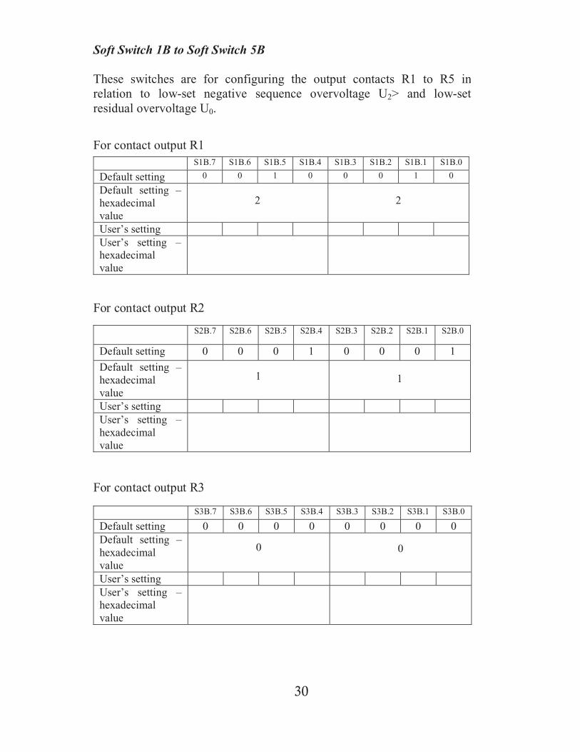
Soft Switch 1B to Soft Switch 5B
These switches are for configuring the output contacts R1 to R5 inrelation to low-set negative sequence overvoltage U2> and low-setresidual overvoltage U0.
For contact output R1
For contact output R2
S1B.7 S1B.6 S1B.5 S1B.4 S1B.3 S1B.2 S1B.1 S1B.0
Default setting 0 0 1 0 0 0 1 0
Default setting –hexadecimalvalue
2 2
User’s settingUser’s setting –hexadecimalvalue
S2B.7 S2B.6 S2B.5 S2B.4 S2B.3 S2B.2 S2B.1 S2B.0
Default setting 0 0 0 1 0 0 0 1
Default setting –hexadecimalvalue
1 1
User’s settingUser’s setting –hexadecimalvalue
For contact output R3
S3B.7 S3B.6 S3B.5 S3B.4 S3B.3 S3B.2 S3B.1 S3B.0
Default setting 0 0 0 0 0 0 0 0Default setting –hexadecimalvalue
0 0
User’s settingUser’s setting –hexadecimalvalue
31
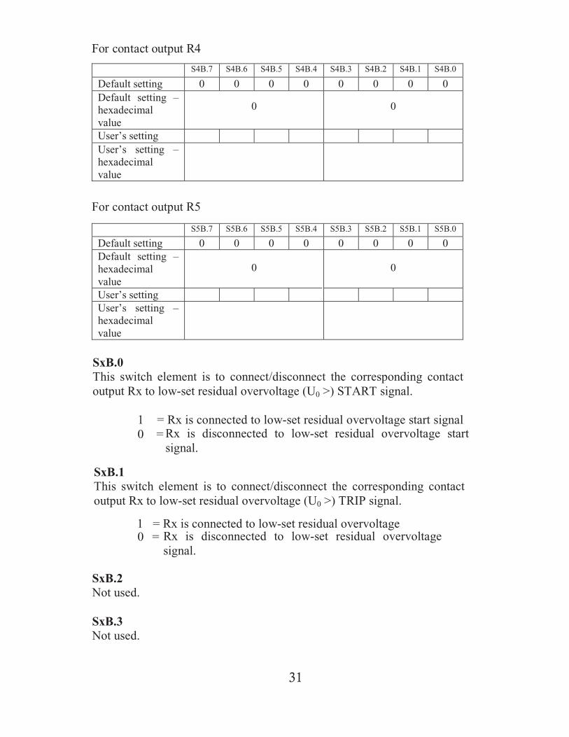
For contact output R4
For contact output R5
S4B.7 S4B.6 S4B.5 S4B.4 S4B.3 S4B.2 S4B.1 S4B.0
Default setting 0 0 0 0 0 0 0 0Default setting –hexadecimalvalue
0 0
User’s settingUser’s setting –hexadecimalvalue
S5B.7 S5B.6 S5B.5 S5B.4 S5B.3 S5B.2 S5B.1 S5B.0
Default setting 0 0 0 0 0 0 0 0Default setting –hexadecimalvalue
0 0
User’s settingUser’s setting –hexadecimalvalue
SxB.0This switch element is to connect/disconnect the corresponding contactoutput Rx to low-set residual overvoltage (U0 >) START signal.
1 = Rx is connected to low-set residual overvoltage start signal0 = Rx is disconnected to low-set residual overvoltage start
signal.
SxB.1This switch element is to connect/disconnect the corresponding contactoutput Rx to low-set residual overvoltage (U0 >) TRIP signal.
1 = Rx is connected to low-set residual overvoltageRx is disconnected to low-set residual overvoltagesignal.
SxB.2Not used.
SxB.3Not used.
0 =
32
0 =
SxB.4This switch element is to connect/disconnect the corresponding contactoutput Rx to low-set negative sequence overvoltage (U2 >) START signal.
1 = Rx is connected to low-set negative sequence overvoltagestart signal.
Rx is disconnected to low-set negative sequenceovervoltage start signal
SxB.5This switch element is to connect/disconnect the corresponding contactoutput Rx to low-set negative sequence overvoltage (U2 >) TRIP signal.
1 = Rx is connected to low-set negative sequence overvoltagetrip signal.
0 = Rx is disconnected to low-set negative sequence overvoltagetrip signal.
SxB.6Not used.
SxB.7Not used.
33
S6A.7 S6A.6 S6A.5 S6A.4 S6A.3 S6A.2 S6A.1 S6A.0
Default setting 0 0 0 0 0 0 0 0Default setting –hexadecimalvalue
0 0
User’s settingUser’s setting –hexadecimalvalue
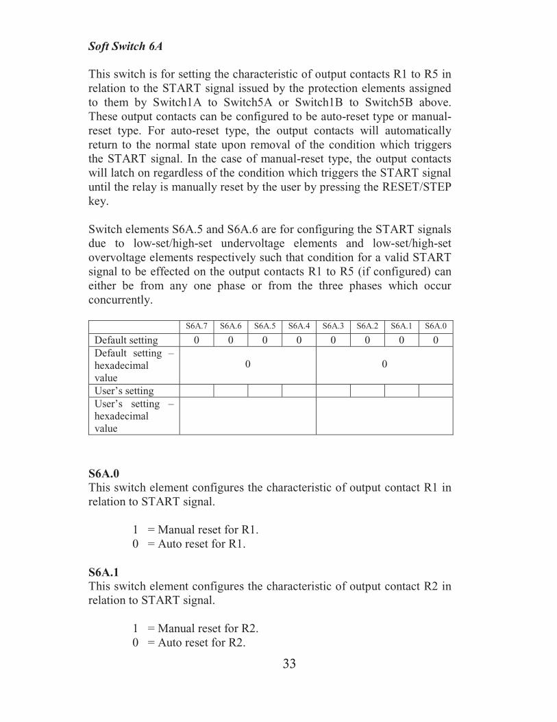
Soft Switch 6A
This switch is for setting the characteristic of output contacts R1 to R5 inrelation to the START signal issued by the protection elements assignedto them by Switch1A to Switch5A or Switch1B to Switch5B above.These output contacts can be configured to be auto-reset type or manual-reset type. For auto-reset type, the output contacts will automaticallyreturn to the normal state upon removal of the condition which triggersthe START signal. In the case of manual-reset type, the output contactswill latch on regardless of the condition which triggers the START signaluntil the relay is manually reset by the user by pressing the RESET/STEPkey.
Switch elements S6A.5 and S6A.6 are for configuring the START signalsdue to low-set/high-set undervoltage elements and low-set/high-setovervoltage elements respectively such that condition for a valid STARTsignal to be effected on the output contacts R1 to R5 (if configured) caneither be from any one phase or from the three phases which occurconcurrently.
S6A.0This switch element configures the characteristic of output contact R1 inrelation to START signal.
1 = Manual reset for R1.0 = Auto reset for R1.
S6A.1This switch element configures the characteristic of output contact R2 inrelation to START signal.
1 = Manual reset for R2.0 = Auto reset for R2.

34
S6A.2This switch element configures the characteristic of output contact R3 inrelation to START signal.
1 = Manual reset for R3.0 = Auto reset for R3.
S6A.3This switch element configures the characteristic of output contact R4 inrelation to START signal.
1 = Manual reset for R4.0 = Auto reset for R4.
S6A.4This switch element configures the characteristic of output contact R5 inrelation to START signal.
1 = Manual reset for R5.0 = Auto reset for R5.
S6A.5This switch element configures the START signal from low-set or high-set undervoltage elements for R1 to R5 above.
1 =All three phases of the low-set or high-set undervoltageelements must start concurrently for a valid START signalto be delivered to R1 to R5.
0 = Any single or more phases low-set or high-set undervoltageelements can trigger a valid START signal to R1 to R5.
S6A.6This switch element configures the START signal from low-set or high-set overvoltage elements for R1 to R5 above.
1 =All three phases of the low-set or high-set overvoltageelements must start concurrently for a valid START signalto be delivered to R1 to R5.
0 = Any single or more phases low-set or high-set overvoltageelements can trigger a valid START signal to R1 to R5.
S6A.7Not used.

35
S6B.7 S6B.6 S6B.5 S6B.4 S6B.3 S6B.2 S6B.1 S6B.0
Default setting 0 0 0 0 0 0 0 0Default setting –hexadecimalvalue
0 0
User’s settingUser’s setting –hexadecimalvalue
Soft Switch 6B
This switch is for setting the characteristic of output contacts R1 to R5 inrelation to the TRIP signal issued by the protection elements assigned tothem by Switch1A to Switch5A or Switch1B to Switch5B above. Theseoutput contacts can be configured to be auto-reset type or manual-resettype. For auto-reset type, the output contacts will automatically return tothe normal state upon removal of the condition which triggers the TRIPsignal. In the case of manual-reset type, the output contacts will latch onregardless of the condition which triggers the TRIP signal until the relayis manually reset by the user by pressing the RESET/STEP key.
Switch elements S6B.5 and S6B.6 are for configuring the TRIP signalsdue to low-set/high-set undervoltage elements and low-set/high-setovervoltage elements respectively such that condition for a valid TRIPsignal to be effected on the output contacts R1 to R5 (if configured) caneither be from any one phase or from the three phases which occurconcurrently.
S6B.0This switch element configures the characteristic of output contact R1 inrelation to TRIP signal.
1 = Manual reset for R1.0 = Auto reset for R1.
S6B.1This switch element configures the characteristic of output contact R2 inrelation to TRIP signal.
1 = Manual reset for R2.0 = Auto reset for R2.

36
S6B.2This switch element configures the characteristic of output contact R3 inrelation to TRIP signal.
1 = Manual reset for R3.0 = Auto reset for R3.
S6B.3This switch element configures the characteristic of output contact R4 inrelation to TRIP signal.
1 = Manual reset for R4.0 = Auto reset for R4.
S6B.4This switch element configures the characteristic of output contact R5 inrelation to TRIP signal.
1 = Manual reset for R5.0 = Auto reset for R5.
S6B.5This switch element configures the TRIP signal from low-set or high-setundervoltage elements for R1 to R5 above.
1 =All three phases of the low-set or high-set undervoltageelements must TRIP concurrently for a valid TRIP signal tobe delivered to R1 to R5.
0 =Any single or more phases low-set or high-set undervoltageelements can trigger a valid TRIP signal to R1 to R5.
S6B.6This switch element configures the TRIP signal from low-set or high-setovervoltage elements for R1 to R5 above.
1 =All three phases of the low-set or high-set overvoltageelements must TRIP concurrently for a valid TRIP signal tobe delivered to R1 to R5.
0 =Any single or more phases low-set or high-set overvoltageelements can trigger a valid TRIP signal to R1 to R5.
S6B.7Not used.

37
S7.7 S7.6 S7.5 S7.4 S7.3 S7.2 S7.1 S7.0Default setting 1 1 1 1 1 1 1 1Default setting –hexadecimalvalue
F F
User’s settingUser’s setting –hexadecimalvalue
S7.0Group A low-set undervoltage time delay setting.
1 = Inverse time0 = Definite time
S7.1Group A low-set overvoltage time delay setting.
1 = Inverse time0 = Definite time
S7.2Group A low-set negative sequence overvoltage time delay setting.
1 = Inverse time0 = Definite time
(Group A)(Group B)
Soft Switch 7
This soft switch allows the user to choose between definite time settingand inverse time setting for the low-set undervoltage, low-set over-voltage, low-set negative sequence overvoltage and low-set residualovervoltage.
There are two groups of settings available for the above protectionelements namely, Group A and Group B. All of the settings can beindividually set for either definite time or inverse time. Switch elementsS7.0 to S7.3 are for Group A settings and S7.4 to S7.7 are for Group Bsettings.

38
S7.3Group A low-set residual overvoltage time delay setting.
1 = Inverse time0 = Definite time
S7.4Group B low-set undervoltage time delay setting.
1 = Inverse time0 = Definite time
S7.5Group B low-set overvoltage time delay setting.
1 = Inverse time0 = Definite time
S7.6Group B low-set negative sequence overvoltage time delay setting.
1 = Inverse time0 = Definite time
S7.7Group B low-set residual overvoltage time delay setting.
1 = Inverse time0 = Definite time

39
Soft Switch 8
This soft switch allows the user to enable or disable the high-setundervoltage, high-set overvoltage, low-set residual overvoltage and low-set negative sequence overvoltage for both Group A and Group B
S8.7 S8.6 S8.5 S8.4 S8.3 S8.2 S8.1 S8.0Default setting 1 1 1 1 1 1 1 1Default setting –hexadecimalvalue
F F
User’s settingUser’s setting –hexadecimalvalue
S8.0For enabling Group A high-set undervoltage element.
1 = Enabled0 = Disabled
S8.1For enabling Group A high-set overvoltage element.
1 = Enabled0 = Disabled
S8.2For enabling Group A low-set residual overvoltage
1 = Enabled0 = Disabled
S8.3For enabling Group A low-set negative sequence overvoltage
1 = Enabled0 = Disabled
(Group B) (Group A)
40
S8.4For enabling Group B high-set undervoltage element.
1 = Enabled0 = Disabled
S8.5For enabling Group B high-set overvoltage element.
1 = Enabled0 = Disabled
S8.6For enabling Group B low-set residual overvoltage
1 = Enabled0 = Disabled
S8.7For enabling Group A low-set negative sequence overvoltage
1 = Enabled0 = Disabled
41
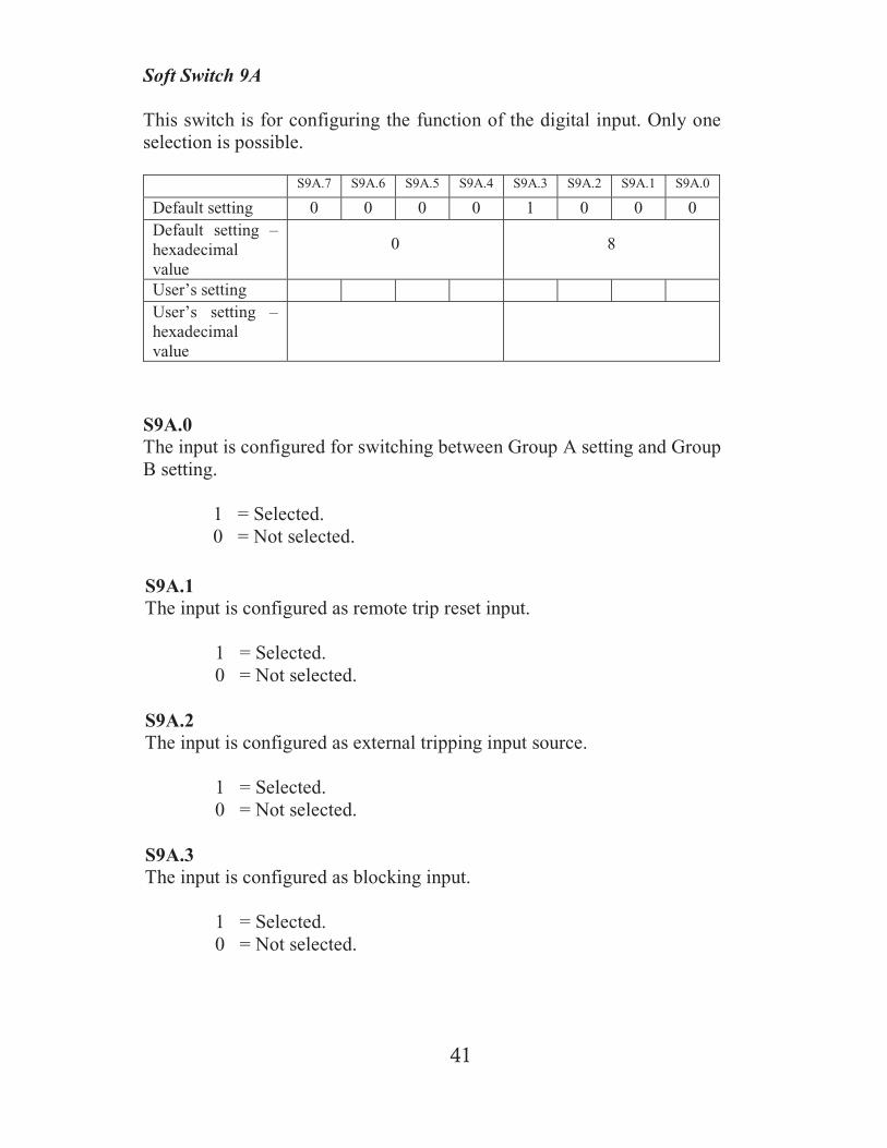
Soft Switch 9A
This switch is for configuring the function of the digital input. Only oneselection is possible.
S9A.7 S9A.6 S9A.5 S9A.4 S9A.3 S9A.2 S9A.1 S9A.0
Default setting 0 0 0 0 1 0 0 0Default setting –hexadecimalvalue
0 8
User’s settingUser’s setting –hexadecimalvalue
S9A.0The input is configured for switching between Group A setting and GroupB setting.
1 = Selected.0 = Not selected.
S9A.1The input is configured as remote trip reset input.
1 = Selected.0 = Not selected.
S9A.2The input is configured as external tripping input source.
1 = Selected.0 = Not selected.
S9A.3The input is configured as blocking input.
1 = Selected.0 = Not selected.
42
S9A.4Not used.
S9A.5Not used.
S9A.6Not used.
S9A.7Not used.
43
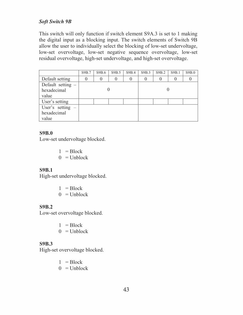
Soft Switch 9B
This switch will only function if switch element S9A.3 is set to 1 makingthe digital input as a blocking input. The switch elements of Switch 9Ballow the user to individually select the blocking of low-set undervoltage,low-set overvoltage, low-set negative sequence overvoltage, low-setresidual overvoltage, high-set undervoltage, and high-set overvoltage.
S9B.7 S9B.6 S9B.5 S9B.4 S9B.3 S9B.2 S9B.1 S9B.0
Default setting 0 0 0 0 0 0 0 0Default setting –hexadecimalvalue
0 0
User’s settingUser’s setting –hexadecimalvalue
S9B.0Low-set undervoltage blocked.
1 = Block0 = Unblock
S9B.1High-set undervoltage blocked.
1 = Block0 = Unblock
S9B.2Low-set overvoltage blocked.
1 = Block0 = Unblock
S9B.3High-set overvoltage blocked.
1 = Block0 = Unblock

44
S9B.4Low-set negative sequence overvoltage blocked.
1 = Block0 = Unblock
S9B.5Low-set residual overvoltage blocked.
1 = Block0 = Unblock
S9B.6Not used.
S9B.7Not used.
45
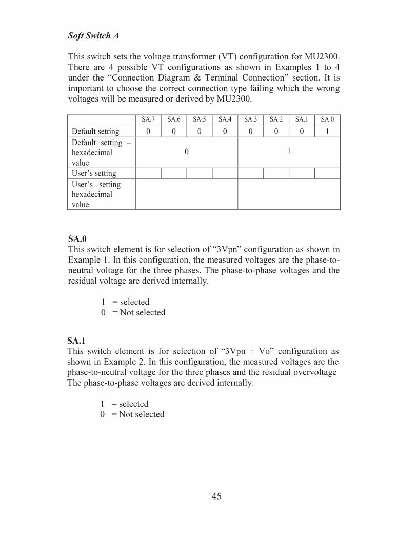
SA.7 SA.6 SA.5 SA.4 SA.3 SA.2 SA.1 SA.0
Default setting 0 0 0 0 0 0 0 1Default setting –hexadecimalvalue
0 1
User’s settingUser’s setting –hexadecimalvalue
Soft Switch A
This switch sets the voltage transformer (VT) configuration for MU2300.There are 4 possible VT configurations as shown in Examples 1 to 4under the “Connection Diagram & Terminal Connection” section. It isimportant to choose the correct connection type failing which the wrongvoltages will be measured or derived by MU2300.
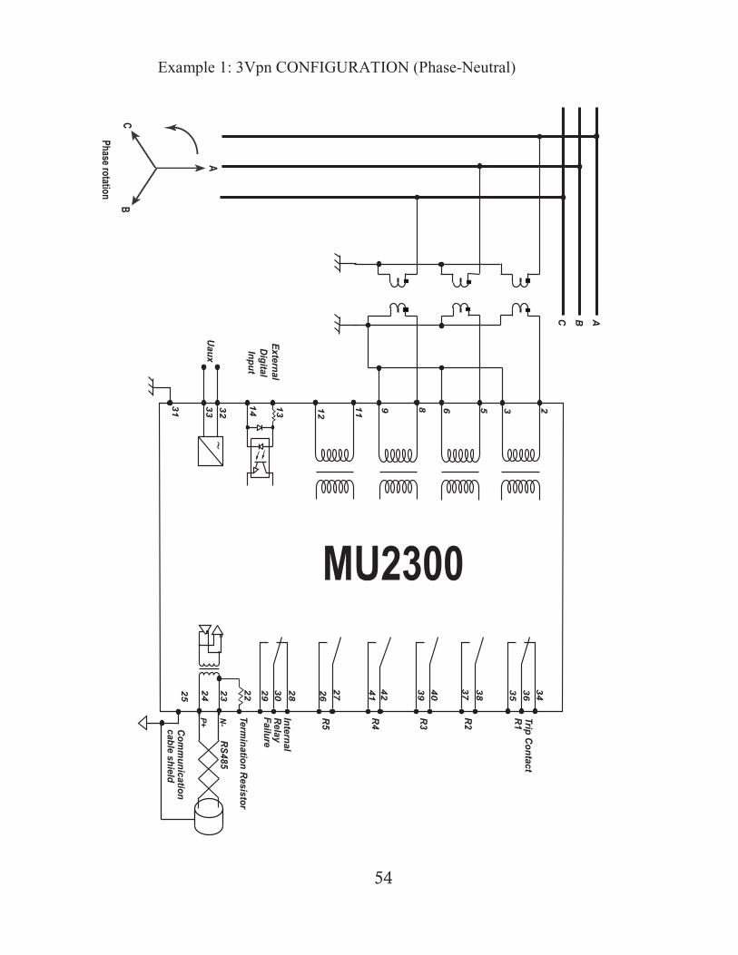
SA.0This switch element is for selection of “3Vpn” configuration as shown inExample 1. In this configuration, the measured voltages are the phase-to-neutral voltage for the three phases. The phase-to-phase voltages and theresidual voltage are derived internally.
1 = selected0 = Not selected
SA.1This switch element is for selection of “3Vpn + Vo” configuration asshown in Example 2. In this configuration, the measured voltages are thephase-to-neutral voltage for the three phases and the residual overvoltageThe phase-to-phase voltages are derived internally.
1 = selected0 = Not selected
46
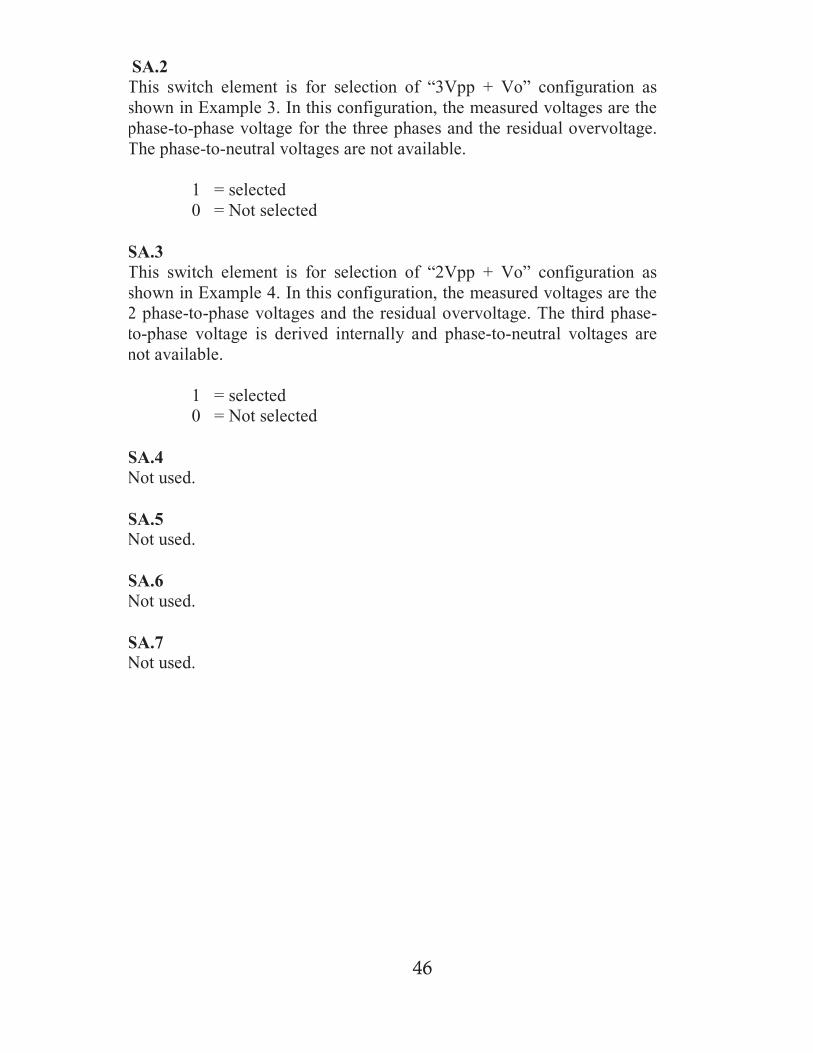
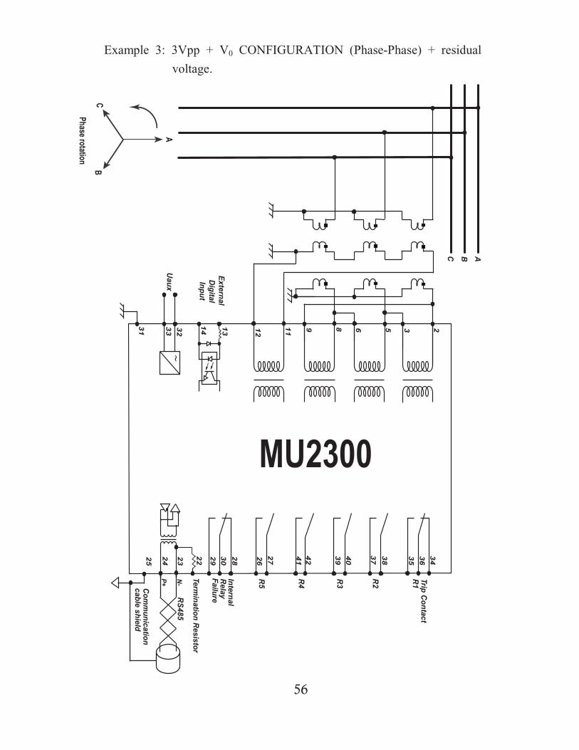
SA.2This switch element is for selection of “3Vpp + Vo” configuration asshown in Example 3. In this configuration, the measured voltages are thephase-to-phase voltage for the three phases and the residual overvoltage.The phase-to-neutral voltages are not available.
1 = selected0 = Not selected
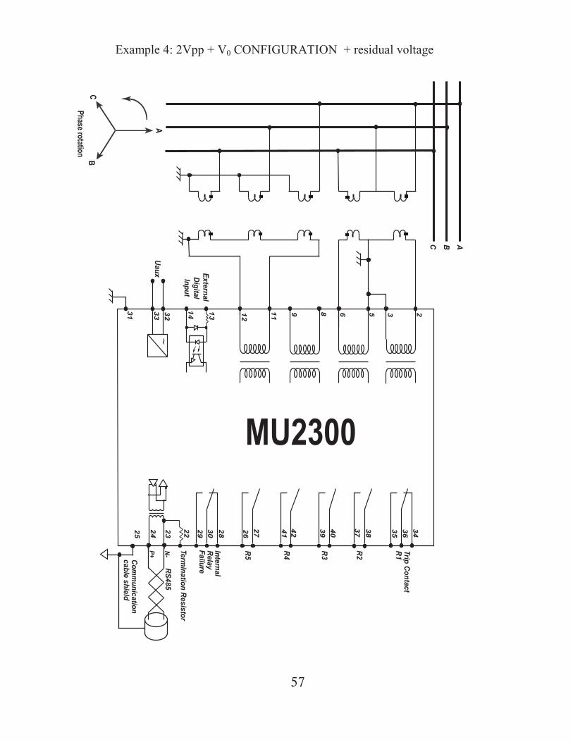
SA.3This switch element is for selection of “2Vpp + Vo” configuration asshown in Example 4. In this configuration, the measured voltages are the2 phase-to-phase voltages and the residual overvoltage. The third phase-to-phase voltage is derived internally and phase-to-neutral voltages arenot available.
1 = selected0 = Not selected
SA.4Not used.
SA.5Not used.
SA.6Not used.
SA.7Not used.
47
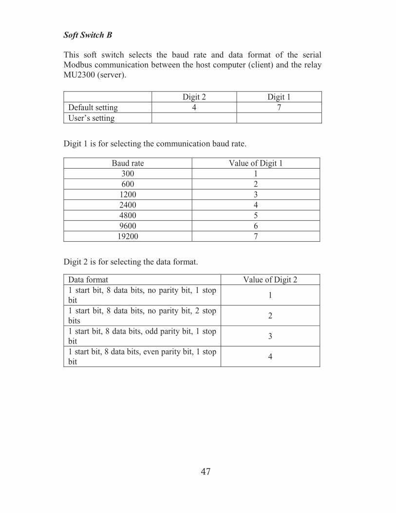
Soft Switch B
This soft switch selects the baud rate and data format of the serialModbus communication between the host computer (client) and the relayMU2300 (server).
Digit 2 Digit 1Default setting 4 7User’s setting
Digit 1 is for selecting the communication baud rate.
Baud rate Value of Digit 1300 1600 2
1200 32400 44800 59600 6
19200 7
Digit 2 is for selecting the data format.
Data format Value of Digit 21 start bit, 8 data bits, no parity bit, 1 stopbit
1
1 start bit, 8 data bits, no parity bit, 2 stopbits
2
1 start bit, 8 data bits, odd parity bit, 1 stopbit
3
1 start bit, 8 data bits, even parity bit, 1 stopbit
4
48
Soft Switch C
This soft switch is for setting the device unit number of MU2300 in aModbus communication network. The setting range for the device unit isfrom 1 to 127 and it is displayed and set in hexadecimal format.
Example:
If the selected unit number is 42, then the equivalent hexadecimal numberis 2A. For conversation between hexadecimal number and decimalnumber, please refer to Appendix B.
The default unit number is 1.

49
Soft Switch D
This soft switch allows the user to either allow or disallow remoteprogramming or changing of the setting values of the MU2300 relay.Once enabled, the remote host computer (client) is able to read andmodify all the settings and parameters of the relay through the serialcommunication channel using Modbus protocol. Otherwise, only readingof the setting values and relay parameters is possible.
1 – Remote programming is enabled.0 – Remote programming is disabled.
The default setting for MU2300 is remote programming disabled (0).
50
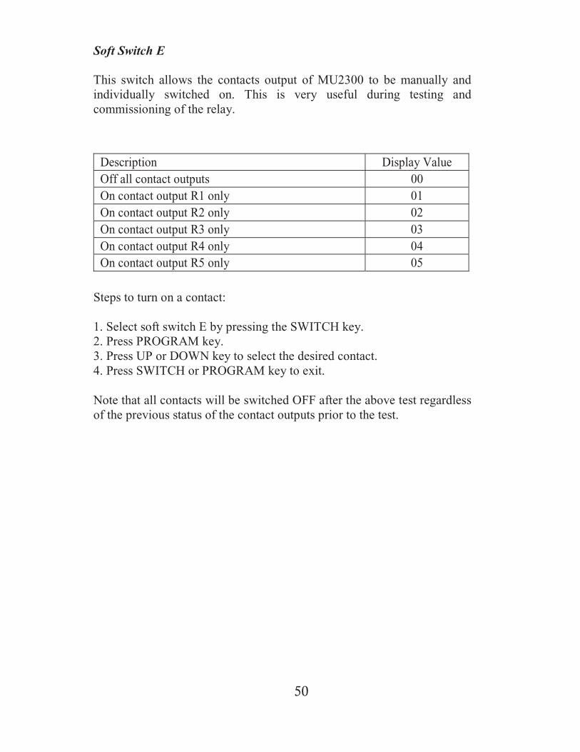
Soft Switch E
This switch allows the contacts output of MU2300 to be manually andindividually switched on. This is very useful during testing andcommissioning of the relay.
Description Display ValueOff all contact outputs 00On contact output R1 only 01On contact output R2 only 02On contact output R3 only 03On contact output R4 only 04On contact output R5 only 05
Steps to turn on a contact:
1. Select soft switch E by pressing the SWITCH key.2. Press PROGRAM key.3. Press UP or DOWN key to select the desired contact.4. Press SWITCH or PROGRAM key to exit.
Note that all contacts will be switched OFF after the above test regardlessof the previous status of the contact outputs prior to the test.

51
Soft Switch F
This switch is for selecting the operation frequency of the electricalsystem to be protected. It is crucial that the correct frequency of operationbe selected and failure to do so will give rise to wrong voltagemeasurements.
0 – 50Hz system frequency1 – 60Hz system frequency

7.1 Terminal Connection
Rear view of MU2300
52
7. Connection Diagram & Terminal Connection
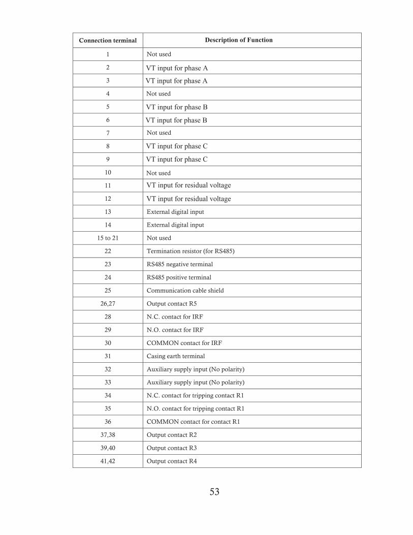
Connection terminal
1
2
3
4
5
6
7
8
9
10
11
12
13 External digital input
14 External digital input
15 to 21 Not used
22 Termination resistor (for RS485)
23 RS485 negative terminal
24 RS485 positive terminal
25 Communication cable shield
26,27 Output contact R5
28 N.C. contact for IRF
29 N.O. contact for IRF
30 COMMON contact for IRF
31 Casing earth terminal
32 Auxiliary supply input (No polarity)
33 Auxiliary supply input (No polarity)
34 N.C. contact for tripping contact R1
35 N.O. contact for tripping contact R1
36 COMMON contact for contact R1
37,38 Output contact R2
39,40 Output contact R3
41,42 Output contact R4
53
Not used
Not used
Not used
Not used
VT input for residual voltage
VT input for residual voltage
VT input for phase A
VT input for phase A
VT input for phase B
VT input for phase B
VT input for phase C
VT input for phase C
Description of Function
54
MU2300
3 26 59 812
11
31 32
33
13
14
3436
35
38
3740
39
4241
2726
28
30
2925
24
2223
ExternalDigitalInput
UauxRS485
Communication
cableshield
FailureRelayInternal
R1
R2R3R4R5
ABC
TripContact
Termination
Resistor
N-
P+A
BC
Phaserotation
Example 1: 3Vpn CONFIGURATION (Phase-Neutral)

55
MU2300
3 26 59 812
11
31 32
33
13
14
34
36
35
38
3740
39
4241
2726
28
30
2925
24
2223
ExternalDigitalInput
UauxRS485
Communication
cableshield
FailureRelayInternal
R1
R2R3R4R5
ABC
TripContact
Termination
Resistor
N-
P+A
BC
Phaserotation
Example 2: 3Vpn + V0 CONFIGURATION (Phase-Neutral) + residualvoltage.
56
MU2300
3 26 59 812
11
31 32
33
13
14
34
36
35
38
3740
39
4241
2726
28
30
2925
24
2223
ExternalDigitalInput
UauxRS485
Communication
cableshield
FailureRelayInternal
R1
R2R3R4R5
ABC
TripContact
Termination
Resistor
N-
P+A
BC
Phaserotation
Example 3: 3Vpp + V0 CONFIGURATION (Phase-Phase) + residual
voltage.
57
MU2300
3 26 59 812
11
31 32
33
13
14
3436
35
38
3740
39
4241
2726
28
30
2925
24
2223
ExternalDigitalInput
UauxRS485
Communication
cableshield
FailureRelayInternal
R1R2R3R4R5
ABC
TripContact
Termination
Resistor
N-
P+A
BC
Phaserotation
Example 4: 2Vpp + V0 CONFIGURATION + residual voltage
198
58
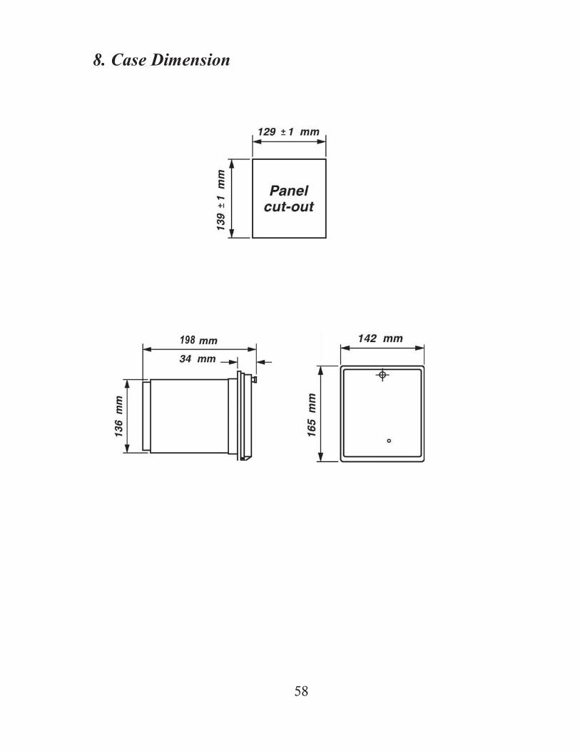
8. Case Dimension

59
9. Technical Data
i) Measuring Inputs Rated Voltage Input * 57-130V Frequency 50Hz or 60Hz
ii) Rated Auxiliary supply voltage
Model MU2300-150D
24~150V DC
Model MU2300-240AD 85~265V AC 110~340V DC
iii) Power Consumption 6-10VA typical (AC auxiliary voltage) 5-9W typical(DC auxiliary voltage)
iv) External Digital Input 80~250V AC/DC *Maximum input voltage is 260V Output i) All contacts Rated voltage 250V AC Continuous carry 5A AC or DC Make and carry for 0.2 sec 30A AC or DC Expected electrical life (min
operation) 5,000,000
Operating time Maximum 15ms Undervoltage element i) Low set Low set setting, U< 5-130V Low set definite time, tU< 0-600s Time multiplier, TMS 0.5-100 ii) High set High set setting, U<< 5-130V High set definite time, tU<< 0-600s iii) Hysteresis 105%
Input
60
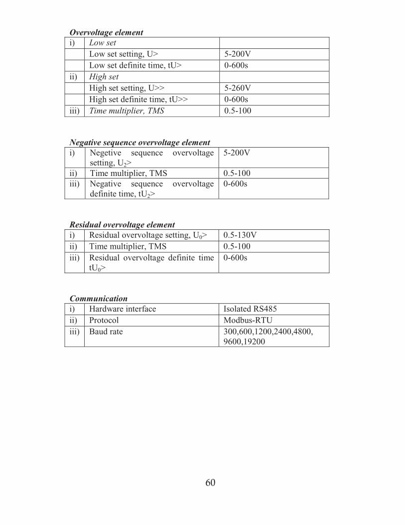
Overvoltage elementi) Low set
Low set setting, U> 5-200VLow set definite time, tU> 0-600s
ii) High setHigh set setting, U>> 5-260VHigh set definite time, tU>> 0-600s
iii) Time multiplier, TMS 0.5-100
Negative sequence overvoltage elementi) Negetive sequence overvoltage
setting, U2>5-200V
ii) Time multiplier, TMS 0.5-100iii) Negative sequence overvoltage
definite time, tU2>0-600s
Residual overvoltage elementi) Residual overvoltage setting, U0> 0.5-130Vii) Time multiplier, TMS 0.5-100iii) Residual overvoltage definite time
tU0>0-600s
Communicationi) Hardware interface Isolated RS485ii) Protocol Modbus-RTUiii) Baud rate 300,600,1200,2400,4800,
9600,19200
61
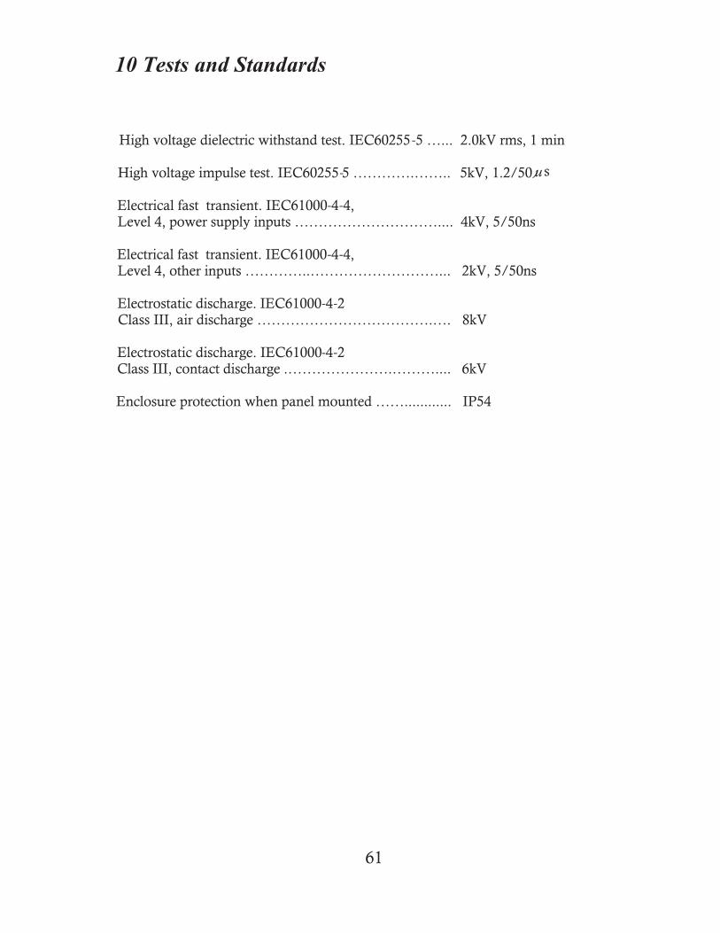
10 Tests and Standards
High voltage dielectric withstand test. IEC60255 -5 …... 2.0kV rms, 1 min
High voltage impulse test. IEC60255-5 ………….…….. 5kV, 1.2/50 s
Electrical fast transient. IEC61000-4-4,Level 4, power supply inputs ………………………….... 4kV, 5/50ns
Electrical fast transient. IEC61000-4-4,Level 4, other inputs …………..………………………... 2kV, 5/50ns
Electrostatic discharge. IEC61000-4-2Class III, air discharge ……………………………….…. 8kV
Electrostatic discharge. IEC61000-4-2Class III, contact discharge .………………….……….... 6kV
Enclosure protection when panel mounted ……............ IP54
u
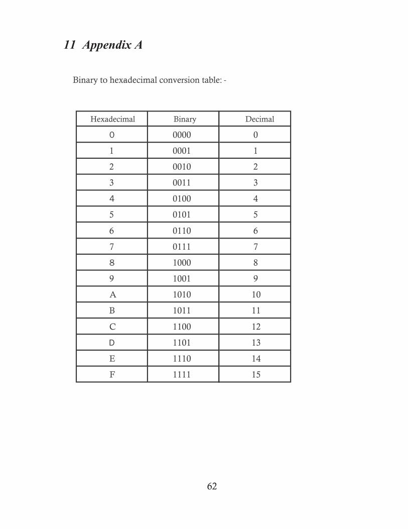
Binary to hexadecimal- conversion table: -
Hexadecimal Binary
0 0000
1 0001
2 0010
3 0011
4 0100
5 0101
6 0110
7 0111
8 1000
9 1001
A 1010
B 1011
C 1100
D 1101
E 1110
F 1111
Decimal
0
1
2
3
4
5
6
7
8
9
10
11
12
13
14
15
62
11 Appendix A

Decimal to Hexadecimal Conversation
Decimal Hexadecimal Decimal Hexadecimal Decimal Hexadecimal1 1 44 2C 87 572 2 45 2D 88 583 3 46 2E 89 594 4 47 2F 90 5A5 5 48 30 91 5B6 6 49 31 92 5C7 7 50 32 93 5D8 8 51 33 94 5E9 9 52 34 95 5F10 A 53 35 96 6011 B 54 36 97 6112 C 55 37 98 6213 D 56 38 99 6314 E 57 39 100 6415 F 58 3A 101 6516 10 59 3B 102 6617 11 60 3C 103 6718 12 61 3D 104 6819 13 62 3E 105 6920 14 63 3F 106 6A21 15 64 40 107 6B22 16 65 41 108 6C23 17 66 42 109 6D24 18 67 43 110 6E25 19 68 44 111 6F26 1A 69 45 112 7027 1B 70 46 113 7128 1C 71 47 114 7229 1D 72 48 115 7330 1E 73 49 116 7431 1F 74 4A 117 7532 20 75 4B 118 7633 21 76 4C 119 7734 22 77 4D 120 7835 23 78 4E 121 7936 24 79 4F 122 7A37 25 80 50 123 7B38 26 81 51 124 7C39 27 82 52 125 7D40 28 83 53 126 7E41 29 84 54 127 7F42 2A 85 5543 2B 86 56
63
12 Appendix B
64
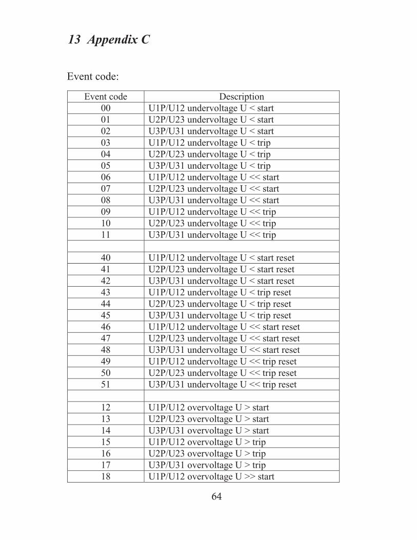
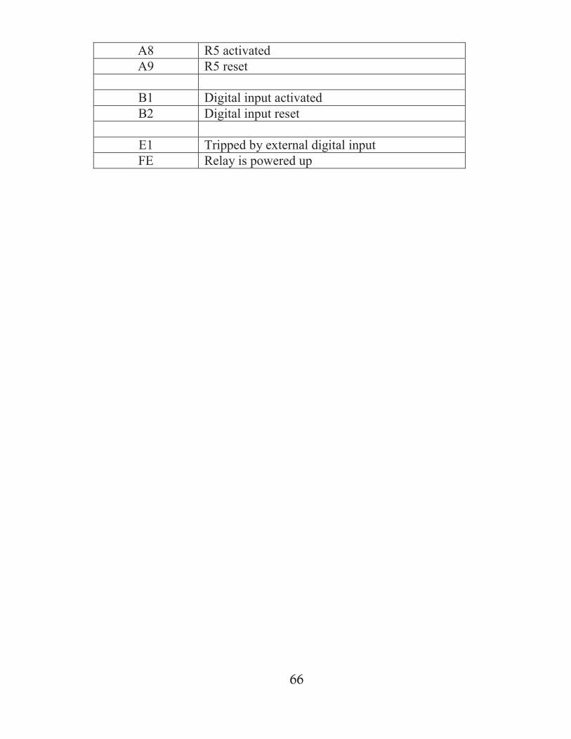
13 Appendix C
Event code:
Event code Description00 U1P/U12 undervoltage U < start01 U2P/U23 undervoltage U < start02 U3P/U31 undervoltage U < start03 U1P/U12 undervoltage U < trip04 U2P/U23 undervoltage U < trip05 U3P/U31 undervoltage U < trip06 U1P/U12 undervoltage U << start07 U2P/U23 undervoltage U << start08 U3P/U31 undervoltage U << start09 U1P/U12 undervoltage U << trip10 U2P/U23 undervoltage U << trip11 U3P/U31 undervoltage U << trip
40 U1P/U12 undervoltage U < start reset41 U2P/U23 undervoltage U < start reset42 U3P/U31 undervoltage U < start reset43 U1P/U12 undervoltage U < trip reset44 U2P/U23 undervoltage U < trip reset45 U3P/U31 undervoltage U < trip reset46 U1P/U12 undervoltage U << start reset47 U2P/U23 undervoltage U << start reset48 U3P/U31 undervoltage U << start reset49 U1P/U12 undervoltage U << trip reset50 U2P/U23 undervoltage U << trip reset51 U3P/U31 undervoltage U << trip reset
12 U1P/U12 overvoltage U > start13 U2P/U23 overvoltage U > start14 U3P/U31 overvoltage U > start15 U1P/U12 overvoltage U > trip16 U2P/U23 overvoltage U > trip17 U3P/U31 overvoltage U > trip18 U1P/U12 overvoltage U >> start
65
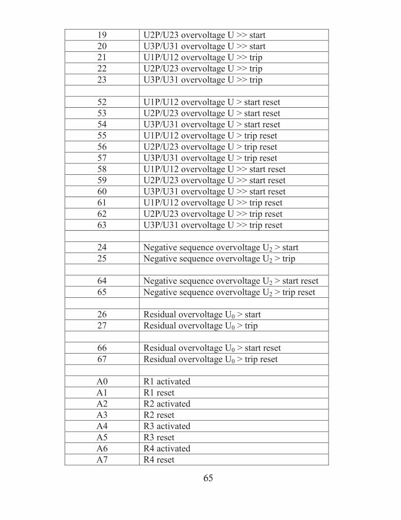
19 U2P/U23 overvoltage U >> start20 U3P/U31 overvoltage U >> start21 U1P/U12 overvoltage U >> trip22 U2P/U23 overvoltage U >> trip23 U3P/U31 overvoltage U >> trip
52 U1P/U12 overvoltage U > start reset53 U2P/U23 overvoltage U > start reset54 U3P/U31 overvoltage U > start reset55 U1P/U12 overvoltage U > trip reset56 U2P/U23 overvoltage U > trip reset57 U3P/U31 overvoltage U > trip reset58 U1P/U12 overvoltage U >> start reset59 U2P/U23 overvoltage U >> start reset60 U3P/U31 overvoltage U >> start reset61 U1P/U12 overvoltage U >> trip reset62 U2P/U23 overvoltage U >> trip reset63 U3P/U31 overvoltage U >> trip reset
24 Negative sequence overvoltage U2 > start25 Negative sequence overvoltage U2 > trip
64 Negative sequence overvoltage U2 > start reset65 Negative sequence overvoltage U2 > trip reset
26 Residual overvoltage U0 > start27 Residual overvoltage U0 > trip
66 Residual overvoltage U0 > start reset67 Residual overvoltage U0 > trip reset
A0 R1 activatedA1 R1 resetA2 R2 activatedA3 R2 resetA4 R3 activatedA5 R3 resetA6 R4 activatedA7 R4 reset
66
A8 R5 activatedA9 R5 reset
B1 Digital input activatedB2 Digital input reset
E1 Tripped by external digital inputFE Relay is powered up

INDUSTRI TEKNOLOGI MIKRO BERHAD,No. 1, Jalan TP 7/7, Sime UEP Industrial Park, 40400 Shah Alam, Selangor, Malaysia.Tel: +603-5192 7155 Fax: +603-5192 7166 Website: www.itmikro.comE-mail: [email protected]
MU2300-150806