users operating manual rg5410a-e - advanced … · users operating manual rg5410a-e amprobe europe...
TRANSCRIPT

USERS OPERATING MANUAL
RG5410A-E
Amprobe Europe GmbH Lürriper Strasse 62 41065 Mönchengladbach Telefon +49(0)2161/59906-0 Telefax +49(0)2161/59906-16
AMPROBE EUROPE RG5410A-E
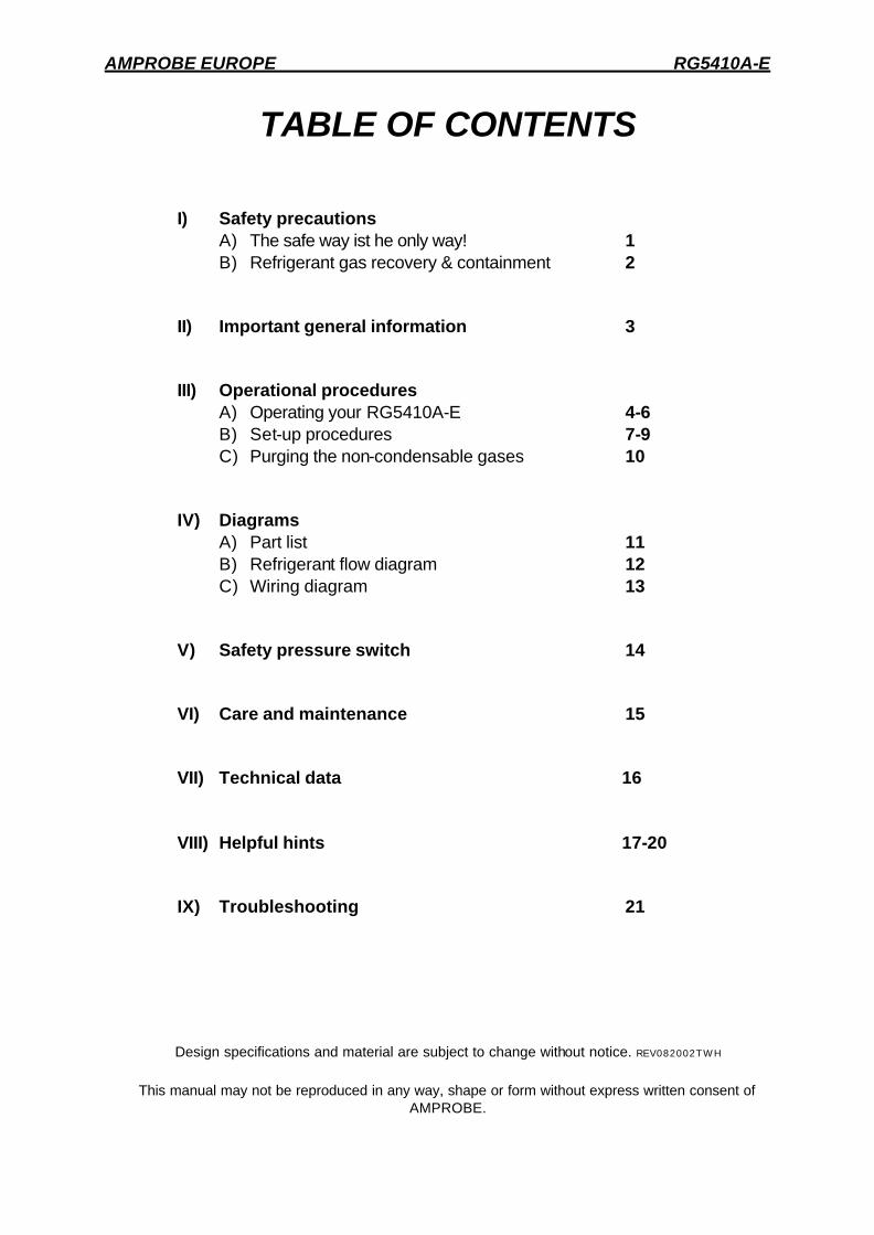
TABLE OF CONTENTS
I) Safety precautions A) The safe way ist he only way! 1 B) Refrigerant gas recovery & containment 2
II) Important general information 3
III) Operational procedures A) Operating your RG5410A-E 4-6 B) Set-up procedures 7-9 C) Purging the non-condensable gases 10
IV) Diagrams A) Part list 11 B) Refrigerant flow diagram 12 C) Wiring diagram 13
V) Safety pressure switch 14
VI) Care and maintenance 15
VII) Technical data 16
VIII) Helpful hints 17-20
IX) Troubleshooting 21
Design specifications and material are subject to change without notice. REV082002TWH
This manual may not be reproduced in any way, shape or form without express written consent of
AMPROBE.
AMPROBE EUROPE RG5410A-E
- 1 -
THE SAFE WAY IS THE ONLY WAY!
NOTE! If you are not a qualified refrigerant service technician, do not use this equipment
1. The technician should always wear goggles and gloves when working on refrigeration
systems.
2. Be sure that any room where you are working is thoroughly ventilated,
3. Always think before acting. Familiarity breeds carelessness and carelessnesscan be harmful to your health or, worse, result in death.
4. Read the Material Safety Data Sheets (MSDS) on all compounds with which you are likely to come in contact. Read MSDS on refrigerant and refrigerant oil. Obtain MSDS sheets from your refrigerant supplier.
5. Never use oxygen when testing for leaks. Any oil in contact with oxygen under pressure will form an explosive mixture.
6. Refrigerant systems are generally electrically driven and controlled. Be sure to disconnect the unit from the power source before servicing it.
7. Always store refrigerant containers in a cool, dry place.
8. Always open service and cylinder valves slowly. This allows quick control of the flow of gasses if there is any danger. Once it is determined that there is no danger, the valves may be opened fully.
9. Do not mix refrigerant in a system, a tank or anywhere else. Each type of refrigerant must have its own tank, filters, etc.
10. If moisture enters the refrigerant system, it is likely to cause considerable damage. Keep everything connected with the refrigeration system thoroughly dry and clean.
11. To reduce the risk of fire, avoid the use of extension cords as they may overheat.If you must use an extension cord iit should be a minimum of 14 AWG and not longer than 25ft. This equipment should be used in locations with mechanical ventilation providing at least four air changes per hour, or the equipment should be located at least 45cm (18”) above the floor. Do not use this equipment in the vicinity of spilled or open containers of gasoline or any other flammable liquid.

AMPROBE EUROPE RG5410A-E
- 2 -
REFRIGERANT GAS RECOVERY & CONTAINMENT
Safety comes first. Read all safety information for the safe handling of refrigerant including the Material Safety Data Sheet provided by your refrigerant supplier. Never operate unit in an explosive environment. Wear safety glasses and protective gloves. Work area must be well ventilated. This unit should only be operated by a qualified technician.
*** CAUTION: REFRIGERANT STORE CONTAINERS ***
Use only approved cylinders with a minimum of 41 bar working pressure that serve the current regulations.
NOTE: Recovery cylinders are designed for different pressures. Do not exceed the working pressure of each cylinder. Safety codes recommend that closed tanks not be filled over 80% of volume with liquid. The remaining 20% is called head pressure room.
NEVER TRANSPORT AN OVERFILLED CYLINDER. Refrigerant expands when it gets warm and may cause a tank to explode if overfilled. CYLINDER TEMP. 16 °C 21 °C 38 °C 54 °C 66 °C STARTING WITH CYLINDER 80% FULL BY VOLUME SPACE OCCUPIED BY LIQUID STARTING WITH CYLINDER 90% FULL BY VOLUME SPACE OCCUPIED BY LIQUID
80 % 81% 83% 90% 94%
90% 92% 96% 100%
AMPROBE EUROPE RG5410A-E
- 3 -
IMPORTANT GENERAL INFORMATION
Before operating the RG5410A-E recovery unit, read the following: 1. Always isolate large amounts of refrigerant and close off valves after use so if a leak
should develop anywhere in the system the refrigerant does not escape.
2. Storage cylinders sometimes have valves that are not properly seated when manufactured. Keeping caps on these valves will guard against refrigerant leakage.
3. Always operate the unit on a flat level surface.
4. Your RG5410A-E has one internal pressure shut off switche. If the pressure inside the system should go above 38,5 bar (550 psi), the system will automatically shut itself off.
CAUTION
The 38,5 bar (550 psi) switch does not prevent tank overfill. If your system shuts off on high pressure and is connected to your tank, you may have overfilled your tank and created a very dangerous situation! Take immediate measures to relieve any high pressure and/or tank overfill. 5. WARNING! Never overfill storage tanks. Overfilling may cause tanks to explode.
6. A scale must be used to avoid overfilling the storage tank.
7. Tanks and filters should be designated for one refrigerant only. Before using a tank previously used for another refrigerant, completely empty the tank, evacuate it, purge the tank using dry nitrogen, and re-evacuate it.
8. Special care should be taken when recovering from a burned-out system. Use two high acid capacity filters, in series. Alco type EK-162-F or Sporlan type C-162-F are recommended.
9. When you have finished recovering from the system, flush your RG5410A-E with a small amount of refrigerant oil and a small amount of clean refrigerant to purge off any foreign substances left in the unit.
10. Always empty refrigerant from the unit into a storage tank; see Self Purge/Auto Evacuate procedure. Liquid refrigerant left in the condenser may expand, causing damage to components.
AMPROBE EUROPE RG5410A-E
- 4 -
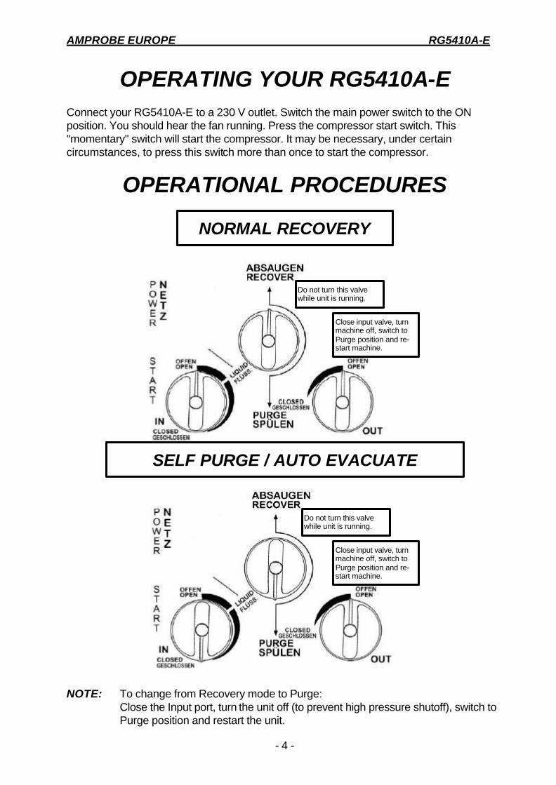
OPERATING YOUR RG5410A-E Connect your RG5410A-E to a 230 V outlet. Switch the main power switch to the ON position. You should hear the fan running. Press the compressor start switch. This "momentary" switch will start the compressor. It may be necessary, under certain circumstances, to press this switch more than once to start the compressor.
OPERATIONAL PROCEDURES
Do not turn this valve while unit is running.
Close input valve, turn machine off, switch to Purge position and re-start machine.
Do not turn this valve while unit is running.
Close input valve, turn machine off, switch to Purge position and re-start machine.
NOTE: To change from Recovery mode to Purge:
Close the Input port, turn the unit off (to prevent high pressure shutoff), switch to Purge position and restart the unit.
NORMAL RECOVERY
SELF PURGE / AUTO EVACUATE
AMPROBE EUROPE RG5410A-E
- 5 -
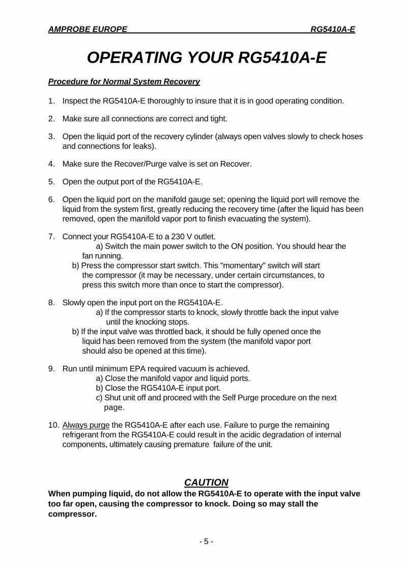
OPERATING YOUR RG5410A-E Procedure for Normal System Recovery 1. Inspect the RG5410A-E thoroughly to insure that it is in good operating condition.
2. Make sure all connections are correct and tight.
3. Open the liquid port of the recovery cylinder (always open valves slowly to check hoses and connections for leaks).
4. Make sure the Recover/Purge valve is set on Recover.
5. Open the output port of the RG5410A-E.
6. Open the liquid port on the manifold gauge set; opening the liquid port will remove the liquid from the system first, greatly reducing the recovery time (after the liquid has been removed, open the manifold vapor port to finish evacuating the system).
7. Connect your RG5410A-E to a 230 V outlet. a) Switch the main power switch to the ON position. You should hear the fan running. b) Press the compressor start switch. This "momentary" switch will start the compressor (it may be necessary, under certain circumstances, to press this switch more than once to start the compressor).
8. Slowly open the input port on the RG5410A-E. a) If the compressor starts to knock, slowly throttle back the input valve until the knocking stops. b) If the input valve was throttled back, it should be fully opened once the liquid has been removed from the system (the manifold vapor port should also be opened at this time).
9. Run until minimum EPA required vacuum is achieved. a) Close the manifold vapor and liquid ports. b) Close the RG5410A-E input port. c) Shut unit off and proceed with the Self Purge procedure on the next page.
10. Always purge the RG5410A-E after each use. Failure to purge the remaining refrigerant from the RG5410A-E could result in the acidic degradation of internal components, ultimately causing premature failure of the unit.
CAUTION When pumping liquid, do not allow the RG5410A-E to operate with the input valve too far open, causing the compressor to knock. Doing so may stall the compressor.

AMPROBE EUROPE RG5410A-E
- 6 -
OPERATING YOUR RG5410A-E Procedure for Purging Remaining Refrigerant From the RG5410A-E 1. Close the ports of the system being serviced that are connected to the input port
of the RG5410A-E.
2. Close the input port on the RG5410A-E.
3. Turn off RG5410A-E.
4. Turn the Recover/Purge valve to the purge position.
5. Restart the RG5410A-E.
6. Run until desired vacuum is achieved.
7. Close the ports on the recovery tank and the RG5410A-E.
8. Turn the RG5410A-E off.
9. Return the Recover/Purge valve to the recover position.
10. Disconnect and store all hoses.
11. Replace the in-line filter on your RG5410A-E after every time excessive contaminant is encountered.
AMPROBE EUROPE RG5410A-E
- 7 -
RG5410A-E REFRIGERANT RECOVERY ADDITIONAL INFORMATION
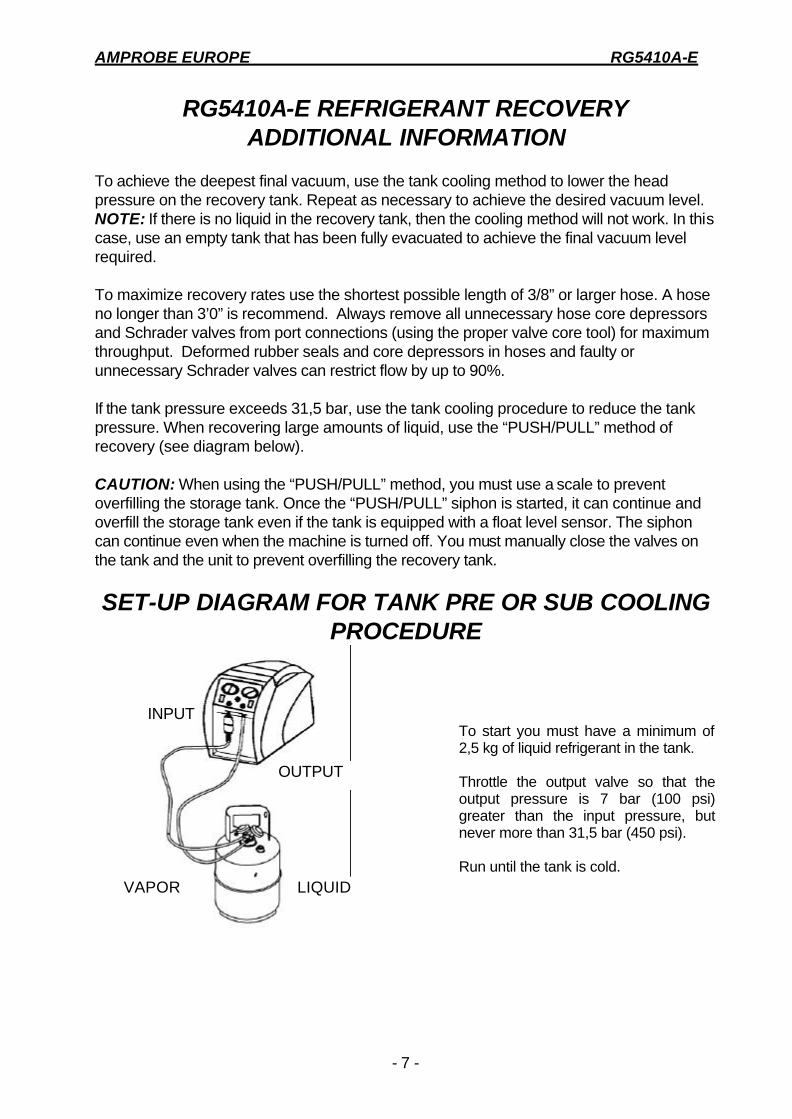
To achieve the deepest final vacuum, use the tank cooling method to lower the head pressure on the recovery tank. Repeat as necessary to achieve the desired vacuum level. NOTE: If there is no liquid in the recovery tank, then the cooling method will not work. In this case, use an empty tank that has been fully evacuated to achieve the final vacuum level required. To maximize recovery rates use the shortest possible length of 3/8” or larger hose. A hose no longer than 3’0” is recommend. Always remove all unnecessary hose core depressors and Schrader valves from port connections (using the proper valve core tool) for maximum throughput. Deformed rubber seals and core depressors in hoses and faulty or unnecessary Schrader valves can restrict flow by up to 90%. If the tank pressure exceeds 31,5 bar, use the tank cooling procedure to reduce the tank pressure. When recovering large amounts of liquid, use the “PUSH/PULL” method of recovery (see diagram below). CAUTION: When using the “PUSH/PULL” method, you must use a scale to prevent overfilling the storage tank. Once the “PUSH/PULL” siphon is started, it can continue and overfill the storage tank even if the tank is equipped with a float level sensor. The siphon can continue even when the machine is turned off. You must manually close the valves on the tank and the unit to prevent overfilling the recovery tank.
SET-UP DIAGRAM FOR TANK PRE OR SUB COOLING PROCEDURE
INPUT
OUTPUT
VAPOR LIQUID
To start you must have a minimum of 2,5 kg of liquid refrigerant in the tank. Throttle the output valve so that the output pressure is 7 bar (100 psi) greater than the input pressure, but never more than 31,5 bar (450 psi). Run until the tank is cold.
AMPROBE EUROPE RG5410A-E
- 8 -
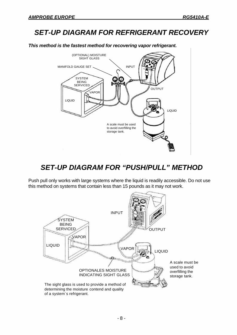
SET-UP DIAGRAM FOR REFRIGERANT RECOVERY This method is the fastest method for recovering vapor refrigerant.
MANIFOLD GAUGE SET
(OPTIONAL) MOISTURE SIGHT GLASS
INPUT
OUTPUT
LIQUID
A scale must be used to avoid overfilling the storage tank.
SYSTEM BEING
SERVICED
VAPOR
LIQUID
SET-UP DIAGRAM FOR “PUSH/PULL” METHOD Push pull only works with large systems where the liquid is readily accessible. Do not use this method on systems that contain less than 15 pounds as it may not work.
SYSTEM BEING
SERVICED
INPUT
OUTPUT
VAPOR LIQUID
LIQUID
VAPOR
OPTIONALES MOISTURE INDICATING SIGHT GLASS
A scale must be used to avoid overfilling the storage tank.
The sight glass is used to provide a method of determining the moisture contend and quality of a system´s refrigerant.

AMPROBE EUROPE RG5410A-E
- 9 -
OPTIONAL RECOVERY / TANK PRE OR SUB COOLING FOR FIXED HOSE SET UP
SYSTEM BEING
SERVICED
LIQUID VAPOR
VAPOR
LIQUID
MANIFOLD GAUGE SET INPUT
OUTPUT
A scale must be used to avoid overfilling the storage tank.
Normal recovery: Tank Vapor valve is closed. Tank pre or sub cooling: Tank Vapor valve is open and both Manifold Gauge Set valves are closed. Follow above procedure.
AMPROBE EUROPE RG5410A-E
- 10 -
RG5410A-E RECOVERY
Purging the non-condensable gasses from identified refrigerant in a tank 1. Allow the tank to sit undisturbed for 24 hours. (This allows the air to rise to the top).
2. Connect a manifold to the tank and read the amount of pressure in the tank by looking at the output pressure gauge.
3. Determine the ambient temperature in the room.
4. Refer to a Refrigerant pressure/temperature chart. Find the temperature on the chart and look across to the corresponding pressure for the type of refrigerant in the tank. Determine how that relates to the reading on the gauge.
5. If the pressure reading is higher than the pressure shown on the chart, very slowly (so as not to cause turbulence inside the tank) crack open the vapor port valve. Watch the pressure on the gauge decrease. To prevent venting, add 0,3 - 0,35 bar (4 - 5 psi) to the pressure shown on the chart. When the gauge corresponds to that pressure, close the vapor port valve.
6. Allow the tank to sit for 10 minutes and check the pressure again.
7. Repeat the process again if necessary.

AMPROBE EUROPE RG5410A-E
- 11 -
Po
s.
Bez
eich
nung
T
eile
nr.
1 P
lasi
c ca
se
1001
34 L
&R
2
Fan
gril
l 10
0505
3
Axi
al fa
n E
L181
8 4
Con
dens
er
1009
78
5 M
otor
E
L182
2 6
Cou
pler
C
P13
15
7 B
ell h
ousi
ng
CP
1001
8
Com
pres
sor
CP
1320
9
Inpu
t gau
ge
GA
1500
10
O
utpu
t gau
ge
GA
0800
11
G
auge
lens
G
A10
00
12
ON
/OF
F s
witc
h E
L131
0 13
S
tart
s sw
itch
EL1
309
14
Blu
e kn
ob
1001
23
15
Red
kno
b 10
0124
16
B
lack
kno
b 10
0122
17
F
ront
pane
l 10
0137
18
F
ilter
10
0343
19
F
lare
cap
N
B65
01
20
Pow
erco
rd
1002
22
21
Pre
ssur
e sw
itch
EL2
802
22
Rea
r pa
nel
1003
18
23
Man
ifold
70
0133
24
F
use
hold
er
1004
19
25
Fus
e 5x
20m
m
1004
06
26
Com
pres
sorb
rack
et
1002
07
27
Hos
e 4“
10
0345
PA
RT
S L
IST
RG
5410
A-E

AMPROBE EUROPE RG5410A-E
- 12 -
RE
FR
IGE
RA
NT
FL
OW
DIA
GR
AM
NO
TE
: A
filte
r mus
t alw
ays
be u
sed.
Fai
lure
to u
se a
filte
r will
inva
lidat
e yo
ur w
arra
nty.
T
he u
se o
f a fi
lter w
ill gr
eatly
redu
ce th
e ris
k of
dam
age
to y
our R
G54
10A-
E b
y pr
even
ting
fore
ign
mat
eria
l fro
m
ente
ring
the
unit.
S
peci
al c
onsi
dera
tion
for
filtra
tion
mus
t be
give
n w
hen
you
know
you
are
ser
vici
ng a
mac
hine
that
has
"Bur
ned
Out
".
We
reco
mm
end
the
use
of tw
o si
ze 1
62 fi
lter d
riers
, in
line,
to b
e us
ed fo
r tha
t job
and
that
job
only
.
FIL
TE
R
OU
TP
UT
INP
UT
CO
ND
EN
SE
R
CO
MP
RE
SS
OR
MO
TO
R
AMPROBE EUROPE RG5410A-E
- 13 -
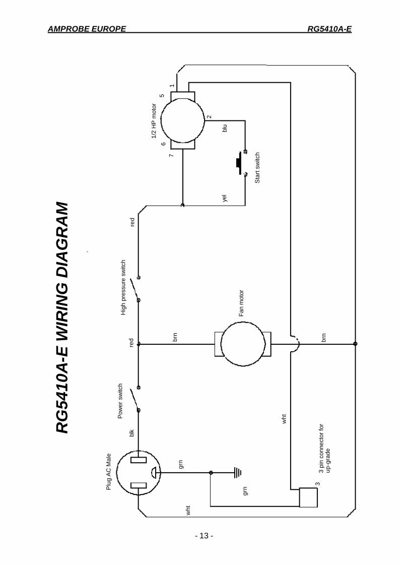
Plu
g A
C M
ale
Pow
er s
witc
h H
igh
pres
sure
sw
itch
Fan
mot
or
3 pi
n co
nnec
tor
for
up
-gra
de
Sta
rt s
witc
h
1/2
HP
mot
or
wh
t
grn
wh
t
grn
blk
brn
brn
red
red
yel
blu
3
2
1
5
7
6
RG
5410
A-E
WIR
ING
DIA
GR
AM

AMPROBE EUROPE RG5410A-E
- 14 -
.SAFETY PRESSURE SWITCH (WITH MANUAL RESET FUNCTION)
The RG5410A-E is equipped with an internal Safety Pressure Switch. If the pressure inside the system exceeds 38,5 bar, the system is switched off automatically. If the Safety Pressure Switch is activated automatically whilst filling a bottle, it could be caused by the bottle becoming overfilled. This is a very dangerous situation! You should take steps immediately to reduce the overpressure and/or to eliminate the overfilling of the bottle.
If the Safety Pressure Switch switches the unit off... The following precautions should be taken if the Safety Pressure Switch is activated: a) Suspected overfilling of the recovery bottle Connect the recovery bottle to another bottle with spare capacity so that the pressure is reduced to a safe level. This action should also reduce the pressure in the output line from the RG5410A-E. Proceed as normal after resetting the Safety Pressure Switch (see below). b) Cause of activation of Safety Pressure Switch unknown 1) Check that the recovery bottle is not overfilled. 2) Close the system valves, recovery bottle valves and RG5410A-E valves. 3) Disconnect RG5410A-E from flexible pipes. 4) Disconnect RG5410A-E from the power supply. 5) Open the input and output valves very slowly. 6) Investigate the reason for the failure. Once activated the Safety Pressure Switch has to be reset manually as follows: I) Remove the black protection cover to reveal the reset button (see picture below). II) Reset by pushing the reset button with a tool such as a screwdriver. III) Replace the cover.
AMPROBE EUROPE RG5410A-E
- 15 -
CARE AND MAINTENANCE OF YOUR RG5410A-E
A filter must always be used and should be replaced frequently. Failure to use a filter will invalidate your warranty. The use of a filter will greatly reduce the risk of damage to your RG5410A-E by preventing foreign material from entering the unit. Special consideration for filtration must be given when you know the machine you are servicing has "burned out". We recommend the use of two size 162 filter driers, in line, to be used for that job and that job only. We also recommend that a clean filter be used for every service job. Each filter should be labeled and used exclusively for one type of refrigerant only. Do not use this unit in the vicinity of spilled or open containers of gasoline or other combustible liquids Avoid the use of extension cords. If you must use an extension cord it should be a minimum of 14 AWG and not longer than 25 ft. Not using an extension cord will greatly reduce the risk of fire. Always purge the unit of any refrigerant left after completing a service job. Refrigerant left in the machine can expand and may cause damage to components. If the unit is to be stored or not used for any length of time, we recommend that it be completely evacuated of any residual refrigerant and purged with dry nitrogen. Whenever you perform any type of maintenance work on your RG5410A-E, insure that it is disconnected from the power supply before you begin.

AMPROBE EUROPE RG5410A-E
- 16 -
TECHNICAL SPECIFICATIONS RG5410A-E
Type RG5410A-E Application Refrigerant recovery Gas or Vapor Suitable refrigerants R12, R22, R134A, R401A, R401B, R401C, R402A, R402B,
R404A, R406A, R407A, R407B, R407C, R407D, R408A, R409A, R410A, R411A, R411B, R412A, R500, R502, R507, R509
Power Source 230V / 50 Hz Power 380 W Dimensions 330 x 229 x 483 mm Weight 14,5 kg Recovery Rate Vapor: up to 33 kg/h Liquid: up to 80 kg/h Push Pull: up to 380 kg/h Displacement 8,2 cm3 (1/2 cubic inch) RPM´s 1437 U/min Max. working pressure 550 p.s.i. (38,5 bar) Safety Device Safety pressure switch type P100 DA with manual reset (550 p.s.i. / 38,5 bar)
ATTENTION The RG5410A-E should not be used with inflammable gases nor with gases containing ammonia.
AMPROBE EUROPE RG5410A-E
- 17 -
HELPFUL HINTS FOR REFRIGERANT RECOVERY
Refrigerant recovery has come a long way in a few short years. On the surface it’s simply the process of taking refrigerant out of a system and putting it into a tank. However, this simple process can quickly become problematic if a few items are overlooked. The following are some tips and pointers we’ve accumulated over the last few years that can save you time and make the process go smoother. First you need to identify the refrigerant type and quantity in the system you are servicing. If you determine it’s a burnout, you need a special tank (a tank that’s identified as containing burnout or other unidentified gases), and you need to use extra filtration prior to recovery. If, on the other hand, you know the gas in the system is relatively clean or new, then a new tank should be used. If you’re planning on putting the refrigerant back into the same system after you have finished the service or if the refrigerant is going to be reclaimed, then use a tank that has the same refrigerant in it. A word of caution about the Environmental Protection Agency (EPA): If you use a variety of refrigerant gasses in your service work - as evidenced by your refrigerant purchases - and you only own one tank, you are asking for trouble. You would be well advised to own at least one tank for every refrigerant type serviced, plus an extra for burnouts and other unknowns. Planning Ahead Knowing the quantity of refrigerant is important for planning storage requirements, as well as planning for the actual recovery. For instance, any system with more than 5lbs. of refrigerant is likely to have areas where the liquid can get trapped. The key to a quick recovery procedure is to get the liquid out first, and then get the remaining vapor out. However most systems are not “recovery friendly.” That is they don’t have access ports at their lowest points. If some units you’re servicing are on maintenance contracts, you would save significant time by installing access ports at all of the lowest points in the system, where liquid is likely to accumulate. Since most systems don’t have these ports you need to be prepared to boil of the trapped liquid with a heat gun, when ever it’s found. An indicator of trapped liquid in a system is frost or condensation forming on the plumbing or components where the liquid is trapped. The trapped liquid may be in an area that is not visible. In all cases trapped liquid in a system during recovery causes the recovery process to slow down, regardless of the size or type of machine If you are unable to locate the trapped liquid (but you know it’s there, because the recovery job is taking “forever”), turn on the system compressor (if it’s operable) for a few seconds. This will get the refrigerant moving to another part of the system and in.
AMPROBE EUROPE RG5410A-E
- 18 -
HOSES AND VALVES Hoses and Schraeder valves have a large impact on recovery speed. In general, the larger the hose, the less friction on the flow of refrigerant, the quicker the recovery time. Many contractors are now using 3/8” lines for the input to the recovery machine, even if those lines originate out of 1/4” fittings. Schraeder valves must be removed from the connection prior to an expedient recovery. Most wholesalers sell a tool for removing these cores, while keeping the connection sealed. The core depressor, in the end of the hose, should also be removed. These two items can turn a 20 minute job into one that goes on for hours. So, be sure to remove Schraeder valves and core depressors before every recovery job. Another hose consideration is the little rubber grommet at the end of the hose that makes a seal with the flare fitting. We’ve seen these seals so worm and deformed that when the hose is connected to the flare fitting the grommet virtually seals off the the connection. This is probably never noticed in charging, because the pressure opens the grommet, but during recovery (or with suction) the deformed grommet severely restricts the flow of refrigerant. Refrigerant Recycling Current regulations state that used refrigerant shall not be sold, or used in a different owner’s equipment, unless the refrigerant has been laboratory analyzed and found to meet the requirements of ARI 700 (latest edition). As a result, recycling and verifying ARI 700 conformance isn’t economically justified in most cases. It’s still a great idea to do as much cleaning of refrigerant going back into the same system (or owners system) as possible. We recommend using the largest, high-acid capacity filter that are economically feasIble. Put these filters on the suction or inlet side of the recovery unit. Change filters often. The recovery of large amounts of liquid refrigerant can sometimes carry with it large quantities of oil, if the system being serviced doesn’t have an adequate oil separator installed. If this recovered refrigerant isn’t going to be liquid charged back into the same system, you might want to separate the refrigerant from the oil in order to measure the oil (to know how much oil to charge back into the system). However refrigerant sent back for reclaim does not need to have the oil removed. One of the simplest and most cost effective ways to achieve this is to use a 30 or 50 lb. tank in line with your recovery machine. Connect the the system to the liquid port of the tank then from the vapor port of the tank connect to the input of your recovery machine a second tank, for storing refrigerant, should then be connected to the output of the recovery machine. If you encounter large amounts of liquid you will need to put a band heater around the first tank. When the recovery job is complete the oil can be removed, from the first tank, by applying a small amount of pressure, using nitrogen, to one of the ports and expressing the oil from the other. If you are going to remove the oil from the vapor port you will need to turn the tank upside down. Always wear safety glasses when performing this operation as the oil may be acidic and could cause severe burning.
AMPROBE EUROPE RG5410A-E
- 19 -
KEEPING THE DIRT OUT During the recovery process your recovery machine can be exposed to debris that can, potentially, damage it. Including brazing spatter and copper and brass slithers. Further contamination can be introduced from the refrigerant storage tanks. To prolong the life of your recovery machine always use an in-line filter. Whenever you are charging a system from a recovery cylinder it is a good idea to use an in-line filter to protect the system from contamination. Again, change your in-line filters often. Getting the Liquid Out (See “Push/Pull-Method”) Push-pull is a method of removing bulk liquid from a system using the pressure differential created by the recovery machine. Push-pull will generally not work on smaller systems because there is no bulk liquid reservoir to create a siphon from. Push-pull is mostly used on systems with a receiver tank or those with greater than 20 lbs. of refrigerant, or when transferring from one tank to another. The rate of liquid transfer id very much dependent on hose size, with larger hoses providing much better throughput. Another trick is to chill the tank, if it’s partially filled, prior or during recovery. This operation will lower the pressure in the storage tank and therefore speed up recovery. There must be a minimum of 5 lbs of liquid refrigerant in the tank you wish to chill. This operation can be performed prior to or during the recovery. See the two set up diagrams and procedures on page 8 of this manual. There is nothing magic here, you are simply using your recovery machine to make a refrigerator where the tank is the evaporator. By throttling the output valve, you’re effectively creating a capillary tube or an expansion device, but you need to adjust the back pressure to suit the conditions and the refrigerant. Five to ten minutes of chilling can produce some very dramatic tank cooling, depending on the conditions. If there are any non condensibles in the tank this process will not work. Also the greater the quantity of refrigerant in the tank the longer the process will take.
AMPROBE EUROPE RG5410A-E
- 20 -
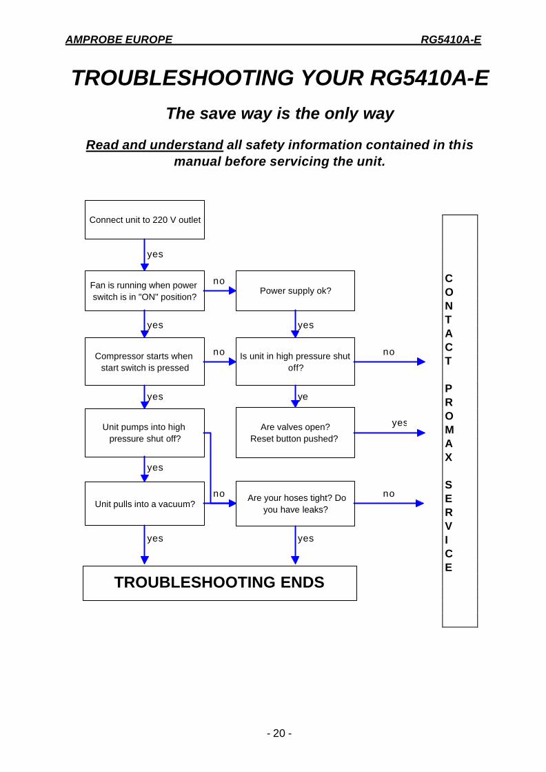
TROUBLESHOOTING YOUR RG5410A-E
The save way is the only way
Read and understand all safety information contained in this manual before servicing the unit.
Connect unit to 220 V outlet
Fan is running when power switch is in "ON" position?
Compressor starts when start switch is pressed
Unit pumps into high pressure shut off?
Power supply ok?
TROUBLESHOOTING ENDS
Are your hoses tight? Do you have leaks?
Unit pulls into a vacuum?
Is unit in high pressure shut off?
Are valves open?Reset button pushed?
yes
no
yes
yes
no
ye
no
yes
yes
no
yes
no
yesyes
C O N T A C T P R O M A X S E R V I C E