usg logix™ integrated systems (english) - is268 · 9 systems guide logix integrated ceiling...
TRANSCRIPT

USG Ceiling Solutions
LOGIX™
Integrated Ceiling Systems
SYSTEMS GUIDE


Logix™ Brand Integrated Ceiling Systems from USG allow you to design ceilings that meet
building requirements without being constrained by the limits of traditional acoustical ceilings.
Logix transforms visual distractions such as lighting, air vents, and other utilities into dramatic
design elements by concentrating these fixtures on narrow channels. This allows for open
ceilings that are uncluttered by ceiling utilities and offer a clean, monolithic, custom look with
standard components.
Logix is compatible with a wide selection of 4 in., 6 in., and 12 in. luminaires and utilities,
as well as 100 mm, 150 mm 300 mm luminaires and utilities.
SYSTEMS GUIDE
Page
Logix Integrated Ceiling Systems Overview
Reflected Ceiling Plan
Definitions
2
Plan Your System Options
Connector Panels
Logix Yoke
12
Design Considerations Layout Options
Drywall Ceilings
Chilled Beams
19
Select Your System 0n-Module Channel Spacing
Off-Module Channel Spacing28
Metric Systems 142
For More Information Technical Service 800 USG.4YOU
Website usg.com

2 Systems Guide Logix Integrated Ceiling Systems
A wide selection of acoustical and specialty panels as well as corresponding suspension
system profiles are available to enhance and customize your design. Plus, with a wide
selection of Logix partners, you can be assured that ceiling utilities will complement your
design and integrate seamlessly into the ceiling.
LOGIX INTEGRATED CEILING SYSTEMS
Office Space
Overview
3 Systems Guide Logix Integrated Ceiling Systems
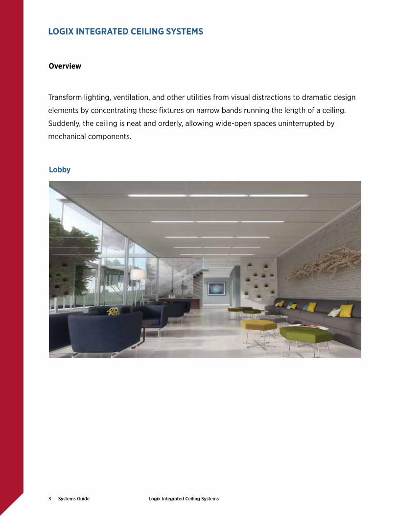
Transform lighting, ventilation, and other utilities from visual distractions to dramatic design
elements by concentrating these fixtures on narrow bands running the length of a ceiling.
Suddenly, the ceiling is neat and orderly, allowing wide-open spaces uninterrupted by
mechanical components.
LOGIX INTEGRATED CEILING SYSTEMS
Lobby
Overview

4 Systems Guide Logix Integrated Ceiling Systems
Accentuate vertical elements and create a custom look without the custom cost while
using standard products, panels, and components. Positioning channels between main
tees allows you to enliven your design with continuous, uninterrupted, decorative, and
functional channels.
Airport
LOGIX INTEGRATED CEILING SYSTEMS
Overview

5 Systems Guide Logix Integrated Ceiling Systems
1 Stabilizer bar required if opening ≥ 60!. For more information about stabilizer bars, please refer to Plank and Large Panel Stabilizer Bars — Application Guide, IC592.
LOGIX INTEGRATED CEILING SYSTEMS
Reflected Ceiling Plan
Example Reflected Ceiling Plan (RCP) Layout 1 1 1
2 4 42
6
27 7
2
2
3
5
5
5
8
5
1 Utility Channel
Infill Panel4
Opening for Luminaire, Mechanical Grille, or Other Utility
2
Channel Panel3
Connector Panel
Yoke
Accessible Stabilizer Bar1
Channel-to-Channel Module Unit

6 Systems Guide Logix Integrated Ceiling Systems
Definitions
Module The module is the measurement basis for coordinating the dimensions of the various suspended ceiling materials and layouts to be designed and constructed.
There are two key module measurements in a Logix ceiling system:
Channel Module The measurement from the centerline of two adjacent utility channels, also referred to as channel-to-channel spacing
Ceiling Module The measurement from the centerline of the suspension system tees installed perpendicular to the utility channels
Module Measurements Channel ModuleCe
iling
Mod
ule
Utilit
y ch
anne
l
Utilit
y ch
anne
l
LOGIX INTEGRATED CEILING SYSTEMS

7 Systems Guide Logix Integrated Ceiling Systems
Definitions
Utility Channel Utility channels are used to organize the lighting, ventilation, and other utilities in narrow bands that facilitate dramatic design elements that are versatile and functional. These narrow suspended ceiling channels are created by main tees or cross tees. The length of utility channels can vary allowing the freedom of various infill layout options.
Imperial Utility Channels
4 in., 6 in., and 12 in.
Metric Utility Channels
100 mm, 150 mm, and 300 mm
Configurations There are four types of configurations used to design a utility channel.
Continuous utility channels are uninterrupted by tees. This is created by main tees that frame the channel.
Fixed utility channels have intersecting tees.This is created by cross tees that frame the channel
Separated utility channels are non-continuous.
Crosscut utility channels have intersecting channels.
Other Ceiling Mounted Devices
•##Air diffusers
•##Sprinkler systems
•##Lighting fixtures
•##Cameras
•##Fire alarms
•##Smoke detectors
•##Speakers
LOGIX INTEGRATED CEILING SYSTEMS

8 Systems Guide Logix Integrated Ceiling Systems
Panels A variety of panel options are available to design a Logix ceiling system. There are three types of panels.
Channel Panel Channel panels are narrow acoustical or metal ceiling panels used in utility channels. Channel panels can be installed in a continuous manner creating a monolithic and uninterrupted aesthetic or in conjunction with lighting, ventilation and other utilities.
Infill Panel Infill panels are larger acoustical or metal ceiling panels installed in the space between utility channels.
Connector Panel Connector panels are a unique option for USG Logix ceiling systems. Connector panels visually connect various utilities in a utility channel such as luminaires and channel panels. Connector panels are configured to carry the adjacent panel or fixture. No special fixture types or tile edges are needed. Connector panels are metal and available in perforated and smooth finishes. Imperial and metric sizes are available.
Definitions
LOGIX INTEGRATED CEILING SYSTEMS

9 Systems Guide Logix Integrated Ceiling Systems
Module Unit A module unit is a representative section of the ceiling system consisting of two utility channels and the adjoining infill panels. Module units can be used to estimate the materials needed to install a ceiling assembly. There are two types of module units.
Off-Module Unit Off-Module units represent assemblies where typical ceiling panel sizes are utilized between the utility channels. With the addition of the utility channel, this creates off-module or nonstandard channel module (channel-to-channel) spacing.
52! Channel Module
On-Module Unit On-Module units represent assemblies where atypical ceiling panel sizes are utilized between the utility channels. With the addition of the utility channel, this creates on-module or a standard channel module (channel-to-channel) spacing.
48! Channel Module
24" 24"4" channel panel 4" channel panel
4in.
cha
nnel
4in.
cha
nnel
52" Channel Module
Typical Infill Panel Size
22" 22"4" channel panel 4" channel panel
4in.
cha
nnel
4in.
cha
nnel
48" Channel Module
Atypical Infill Panel Size
For further module unit options, see page 20.
Definitions
LOGIX INTEGRATED CEILING SYSTEMS

10 Systems Guide Logix Integrated Ceiling Systems
Suspension Systems There are three types of grid suspension systems used in a Logix system.
Donn® DX®/DXL™ Standard
Centricitee™ DXT™Narrow
Identitee™ DXI™Double Reveal
Main Tee Utility Channel
A utility channel created with main tees that frame that channel. This type of channel is used in a continuous utility channel configuration.
Cross Tee Utility Channel
A utility channel created with cross tees that frame the channel. This type of channel is used in a fixed, separated, or crosscut utility channel configuration.
See layout details on page 19.
Cross Tee
Main Tee
Main Tee
Utility Channel
Cross Tee
Main Tee
Cross Tee
Utility Channel
Main Tee
Main Tee
Cross Tee
Cross Tee
Definitions
LOGIX INTEGRATED CEILING SYSTEMS

11 Systems Guide Logix Integrated Ceiling Systems
Yoke The USG Logix Yoke is an optional suspension system installation accessory that facilitates the spacing and suspension of parallel main tees with one hanger wire. The Logix yoke is compatible with both metric and imperial utility channel sizes. The yoke also keeps hanger wire wraps away from linear luminaires and can reduce the number of hanger wires required. The yoke also helps to brace the utility channel.
Accessible Stabilizer Bar The USG Accessible Stabilizer Bar is a suspension system installation accessory used in plank and large panel suspension systems. Specially notched safety bars attach to the main tees and cross tees, which prevents the tee ends from spreading and enhances the rigidity of large ceiling modules.
USG stabilizer bars are available in different sizes and options for various applications. If the panel length is ≥ 60 in., then one stabilizer is required at midpoint. If the panel length is ≥ 96 in., then two stabilizer bars are required at the 1/3 and 2/3 points. These safety bars enhance system performance and safety without limiting accessibility.
See layout details and assemblies on pages 17-18.
Definitions
LOGIX INTEGRATED CEILING SYSTEMS

12 Systems Guide Logix Integrated Ceiling Systems
1 Utility Channel Configuration Continuous Fixed Separated Crosscut
5 Infill Panel Specification Mars™ Mars™ High-NRC Halcyon™ Panz® Metal
Unperforated
True™ Wood
6 Infill Panel Edge Profile Square FL SL FLB SLT
7 Grid Profile DXI Identitee DXT Centricitee Donn DX
8 Channel Panel Specification Mars Mars High-NRC Halcyon Panz Metal
C116D
9 Channel Panel Edge Profile Square FL SL FLB SLT
2 Utility Channel Width Imperial Metric Custom
4!, 6!, 12! 100 mm, 150 mm, 300 mm Contact your Sales Representative for custom options.3 Channel Module Spacing
(Channel-to-Channel)4" 5" 6" 7" 8"-$6!
4"-$4! 5"-$4! 6"-$6! 7"-$6! 10"-$6!
4"-$6! 5"-$6! 12"
1200 mm 1500 mm1300 mm 1900 mm1350 mm 1950 mm
4 Ceiling Module Dimension 4", 5", 6" ceiling module 1.25 m, 1.5 m, 1.75 m ceiling module
Selector Options
PLAN YOUR SYSTEM

13 Systems Guide Logix Integrated Ceiling Systems
Imperial 4! Channel 6! Channel
4" 6"
12! Channel
12"
Metric 100 mm Channel 150 mm Channel
100 mm 150 mm
300 mm Channel
300 mm
Utility Channel Options
PLAN YOUR SYSTEM

14 Systems Guide Logix Integrated Ceiling Systems
Infill Panel Options Halcyon™ Fiberglass Mars™ X-Technology Mineral Fiber
Mars™ High-NRC X-Technology Mineral Fiber
Panz® Unperforated Metal Aluminum
Panz® Wood ToneMetal
True™ WoodNatural Wood Veneers
Unperforated
Channel Panel Options Halcyon™ Fiberglass Mars™ X-Technology Mineral Fiber
Mars™ High-NRC X-Technology Mineral Fiber
Panz® Unperforated Metal Aluminum
Panz® Perforated, C116 Aluminum
Panz® Perforated, C116D Aluminum
Panz® Wood ToneMetal
Unperforated C116 C116D
The panel options listed below correspond to our standard fixed ceiling modules. However, virtually all standard ceiling panels are possible with a continuous utility channel system. Contact your sales representative for more information.
Panel Options
PLAN YOUR SYSTEM

15 Systems Guide Logix Integrated Ceiling Systems
Maximum 2"x$$2" SQ Edge panels with DXT.
Panel Edge Options
FL FLB SL SLT SQ
Suspension Systems
Centricitee™ DXT™
DXT Grid – FL Panel DXT Grid – FLB Panel DXT Grid – SQ Panel PanZ® Metal
DXT Grid – FL PanzTrue™ Wood
DXT Grid – FL True PanelIdentitee™ DXI™
DXI Grid – FL Panel DXI Grid – FLB PanelPanz Metal
DXI Grid – FL PanzDonn® DX®/DXL™
DX Grid – SL Panel DX Grid – SLT Panel DX Grid – SQ Panel True™ Wood
DX Grid – SL True Panel
Suspension System Options
PLAN YOUR SYSTEM

16 Systems Guide Logix Integrated Ceiling Systems
The Logix connector panel is a unique way to visually connect various utilities such as luminaires and channel panels. The connector panels are configured to carry the adjacent panel or fixture. No special fixture types or tile edges are needed.
Options Finish Smooth, Unperforated Perforated, C116 Perforated, C116D
Unperforated
C116 C116D
Color Flat White Painted
Edge Profile Reveal Edge Flush Mount
4! Channel 6! Channel
Imperial 4! x 12! 4! x 24! 6! x 12! 6! x 24!
100 mm Channel 150 mm Channel
Metric 100 mm x 300 mm 100 mm x 600 mm 1500 mm x 300mm 1500 mm x 600 mm
Connector Panels
PLAN YOUR SYSTEM

17 Systems Guide Logix Integrated Ceiling Systems
YokeImperial
4! Channel 6! Channel 12! Channel
8 1/8"
fastener placement(2 required)
4 25/32"
8 1/8"
fastener placement(2 required)
6 25/32" 12 25/32"
fastener placement(4 required)
cut main tee to be used as a bridge to lengthen yoke
8 1/8"
hanger wires (2 required)
YokeMetric
100 mm Channel 150 mm Channel 300 mm Channel
120.40 mm
fastener placement(2 required)
206.38 mm
170.18 mm
206.38 mm
fastener placement(2 required)
206.38 mm
fastener placement(4 required)
cut main tee to be used as a bridge to lengthen yoke
hanger wires (2 required)
320.18 mm
The Logix yoke is compatible with both metric and imperial utility channel sizes. The yoke keeps hanger wire wraps away from linear luminaires and may reduce the number of hanger wires required. The yoke also helps to brace the utility channel. The yoke is easy to install and is seismic tested.
Note: The USG yoke provides connections that exceed the 180 lb. requirement for Seismic Design Categories D-F.
Logix Yoke
PLAN YOUR SYSTEM

18 Systems Guide Logix Integrated Ceiling Systems
Yoke with Connector Panel The Logix yoke is compatible with all utility channel options and applications. The connector panel shown is one of many options allowing the freedom to transform the utilities into dramatic design elements.
The connector panel is secured to the adjacent main tees by folding tabs; the folding tabs should be folded inwards to insure ceiling section alignment.
hanger wire
cross tee
main tee
4" or 6" connector panel
4" or 6" adjustable yoke
secure tab with 1/8" pop-rivet
Yoke with Recessed Linear Luminaires
Logix is compatible with a wide selection of 4!, 6!, and 12! luminaires including Lumination™ LED Luminaires by GE Lighting Solutions. For more information visit: www.gelightingsolutions.com.
hanger wire
cross tee
main tee
lighting fixture
4" or 6" adjustable yoke
Yoke Assemblies
PLAN YOUR SYSTEM

19 Systems Guide Logix Integrated Ceiling Systems
Utility Channel Created with Main Tees
Utility Channel Created with Cross Tees
lighting fixture
hanger wire
main tee
cross tees
If opening is ≥ 60", then one stabilizer bar is required at midpoint.
If opening is ≥ 96", then two stabilizer bars are required at 1/3 and 2/3 points.
utility panel
cross tee
nom. 4" to 12" channel width accommodates continuous fixtures
variable channel width
yoke
connector panel
main tees
variable length fixtures
lighting fixturefield panel
main tee
hanger wire
If opening is ≥ 60", then one stabilizer bar is required at midpoint.
If opening is ≥ 96", then two stabilizer bars are required at 1/3 and 2/3 points.
yoke or two vertical hanger wires
Layout Options
DESIGN CONSIDERATIONS

20 Systems Guide Logix Integrated Ceiling Systems
22"4" 4"22"
48" Channel Module
Ceili
ng M
odul
e
Utili
ty C
hann
el
Utili
ty C
hann
el
24"4" 4"24"
52" Channel Module Off-Module On-Module
48" (4'-0")60" (5'-0") 72" (6'-0") 144" (12'-0")
52" (4'-4")54" (4'-6")64" (5'-4")66" (5'-6")78" (6'-6")90" (7'-6")100" (8'-4")102" (8'-6")126" (10'-6") Ce
iling
Mod
ule
Utili
ty C
hann
el
Utili
ty C
hann
el
Module Unit Module Unit
Off-Module UnitsOff-Module units represent assemblies where typical ceiling panel sizes are utilized between the utility channels. With the addition of the utility channel, this creates off-module or nonstandard channel-to-channel spacing.
On-Module UnitsOn-Module units represent assemblies where atypical ceiling panel sizes are utilized between the utility channels. With the addition of the utility channel, this creates on-module or standard channel-to-channel spacing.
Ceiling Modules
DESIGN CONSIDERATIONS
21 Systems Guide Logix Integrated Ceiling Systems
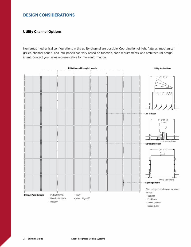
Other ceiling mounted devices not shown such as: • Cameras• Fire Alarms• Smoke Detectors• Speakers, etc.
sprinkler
fixture attachment
4", 6" or 12"
4", 6" or 12"
4", 6" or 12"
Air Diffuser
Utility Applications
Sprinkler System
Lighting Fixture
Channel Panel Options • Perforated Metal• Unperforated Metal• Halcyon™
• Mars™ • Mars™ High-NRC
Utility Channel Example Layouts
Numerous mechanical configurations in the utility channel are possible. Coordination of light fixtures, mechanical grilles, channel panels, and infill panels can vary based on function, code requirements, and architectural design intent. Contact your sales representative for more information.
Utility Channel Options
DESIGN CONSIDERATIONS

22 Systems Guide Logix Integrated Ceiling Systems
Virtually all suspended ceiling systems are possible with a continuous utility channel system. Nearly all suspended ceiling systems can be installed between continuous utility channels. Contact your sales representative for more information.
Standard 2" x 2" Ceiling Layout Standard 2" x 4" Ceiling LayoutStandard 2'x2' Ceiling Layoutwith a continuous utility channel
continuousutility channel
standard 2'x 2'suspended ceiling
Standard 2'x4' Ceiling Layoutwith a continuous utility channel
continuousutility channel
standard 2'x4'suspended ceiling
Standard 30! x 30! Ceiling Layout Standard 4" x 4" Ceiling LayoutStandard 30"x30" Ceiling Layoutwith a continuous utility channel
continuousutility channel
standard 30"x 30"suspended ceiling
Standard 4'x4' Ceiling Layoutwith a continuous utility channel
continuousutility channel
standard 4'x 4'suspended ceiling
DESIGN CONSIDERATIONS
Continuous Utility Channels

23 Systems Guide Logix Integrated Ceiling Systems
DESIGN CONSIDERATIONS
Drywall Ceilings
The USG drywall suspension system is a pre-engineered drywall ceiling system specifically created to simplify the design and construction of drywall ceilings. The system allows you to create unique and conventional drywall ceilings. The system assembles quickly and easily for faster installation and allows for the easy transition to acoustical ceilings, and vertical, horizontal, and curved surfaces. The USG drywall suspension system components come with a 10-year warranty and the system has a lifetime limited warranty when used with USG Sheetrock® Brand gypsum panels.
Integrating linear luminaires with the USG drywall suspension system creates a ceiling with advanced engineering, crisp lines and a strikingly pure aesthetic.
Example Layouts
wall channel
6’ cross tee
main tee
fasteners 6" to 8" o.c.
hanger wire 48" o.c.
adjustable yoke
SHEETROCK gypsum panels
54" wide SHEETROCK gypsum panels

24 Systems Guide Logix Integrated Ceiling Systems
DESIGN CONSIDERATIONS
Drywall Ceilings
Example Layouts
Example Luminaire Applications
Trim Flange Luminaire Trimless LuminaireTrim Flange Luminaire
lighting support bracket
drywall suspension tee
screw attached through drywall into grid
lighting unit trim flange
lighting unit
flush light cover
Trimless Luminaire
drywall suspension tee
screw attached through drywall into grid
tape and mud finished
flush light cover
lighting unit
wall angle
6' cross tee
main tee
fasteners 6" to 8" o.c.
hanger wire 48" o.c.
lighting fixture
SHEETROCK gypsum panels

25 Systems Guide Logix Integrated Ceiling Systems
Chilled beams are part of a convection HVAC system where pipes of water are fed through a heat exchanger called a chilled beam for the purpose of controlling the climate of the space below. Chilled beams can be either active or passive. Active beams provide ventilation air in addition to cooling, while passive beams consist of a cooling coil in an enclosure. Multi-service chilled beams can integrate a variety of other services including speakers, lighting, sprinkler heads, etc. Chilled beams can either be exposed below the suspended ceiling or integrated into the suspended ceiling. Logix is designed to accommodate 12 in. chilled beam fixtures and integrate them into the 12 in. Logix utility channel. Larger chilled beams may be incorporated between utility channels.
Example Layouts
Continuous Utility Channels 12! Chilled Beam Typical 12! x 6" Chilled Beam
12! Chilled Beam Typical 12! x 6" Chilled Beam
DESIGN CONSIDERATIONS
Chilled Beams
12"x 6' chilled beam
30"x 60" infill panel
12" utility channel
12"x 6' chilled beam
2'x 6' infill panel
12" utility channel

26 Systems Guide Logix Integrated Ceiling Systems
Example Layouts
Fixed Utility Channel 12! Chilled Beam Typical 12! x 6" Chilled Beam
Large Chilled Beam 2" x 8" Chilled Beam Between Utility Channels Typical 2" x 8" Chilled Beam
DESIGN CONSIDERATIONS
Chilled Beams
12" x 6' chilled beam
2'x 6' infill panel
12" utility channel
2'x8' infill panel
2'x8' chilled beam
4" or 6" utility channel
Typical 2'x8' Chilled Beam

27 Systems Guide Logix Integrated Ceiling Systems
LogiX Partners Logix is compatible with a wide selection of 4 in., 6 in., and 12 in. luminaires and utilities, as well as 100 mm, 150 mm, and 300 mm luminaires and utilities. lumi-naires and utilities. USG has dedicated a permanent space to test and evaluate compatible products and prequalify them for fit and finish. For more informa-tion about the dimensions of Logix components and assemblies, please refer to IC609 Logix Critical System Dimensions.
Lighting • Amerlux
• A Light
• Focal Point
• GE Lighting
• Zumtobel
Diffuser • Carnes
Sprinkler • SprinkFlex
DESIGN CONSIDERATIONS
Logix Partners

28 Systems Guide LOGIX Integrated Ceiling Systems
Channel Width
Ceiling Module
On-Center Channel Spacing
Infill Panels PANZ Metal Option System Page
InfillPanel
ChannelPanel
4! Channel
4! 4" 4" 22! x 48! 764 34-35
4! 4" 4" 22! x 24! 996 36-37
4! 4" 4" 44! x 24! 952 38-39
4! 4" 4" 44! x 48! 375 40-41
4! 5" 5" 56! x 20! 537 42-43
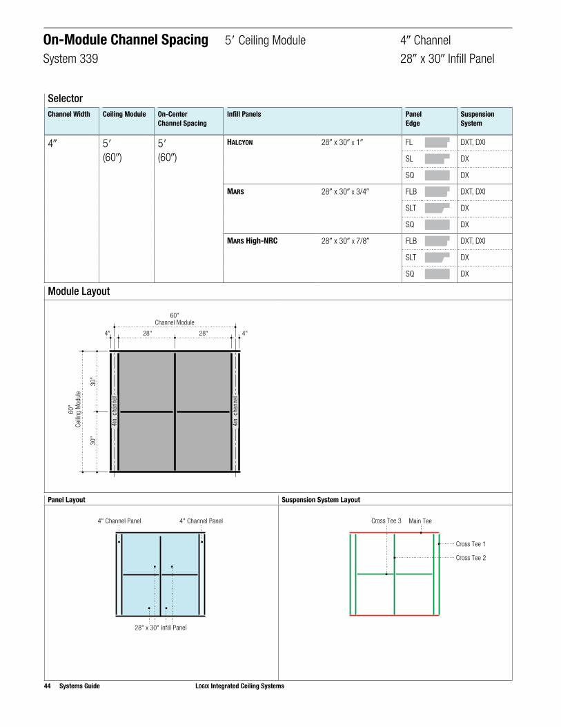
4! 5" 5" 28! x 30! 339 44-45
4! 5" 5" 28! x 60! 433 46-47
4! 5" 5" 56! x 30! 524 48-49
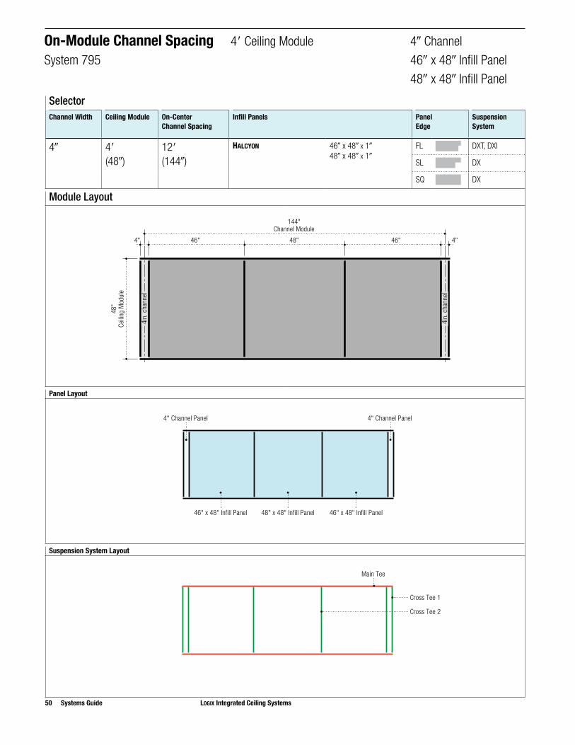
4! 4" 12" 46! x 48! 48! x 48!
795 50-51
On-Module Channel Spacing
4" and 5" Ceiling Modules
Overview

LOGIX Integrated Ceiling Systems Systems Guide 29
On-Module Channel Spacing
4" and 5" Ceiling Modules
Overview
Channel Width
Ceiling Module
On-Center Channel Spacing
Infill Panels PANZ Metal Option System Page
InfillPanel
ChannelPanel
6! Channel
6! 4" 4" 42! x 48! • 346 52-53
6! 4" 4" 42! x 24! • 727 54-55
6! 4" 4" 21! x 24! • 838 56-57
6! 4" 4" 21! x 48! • 646 58-59
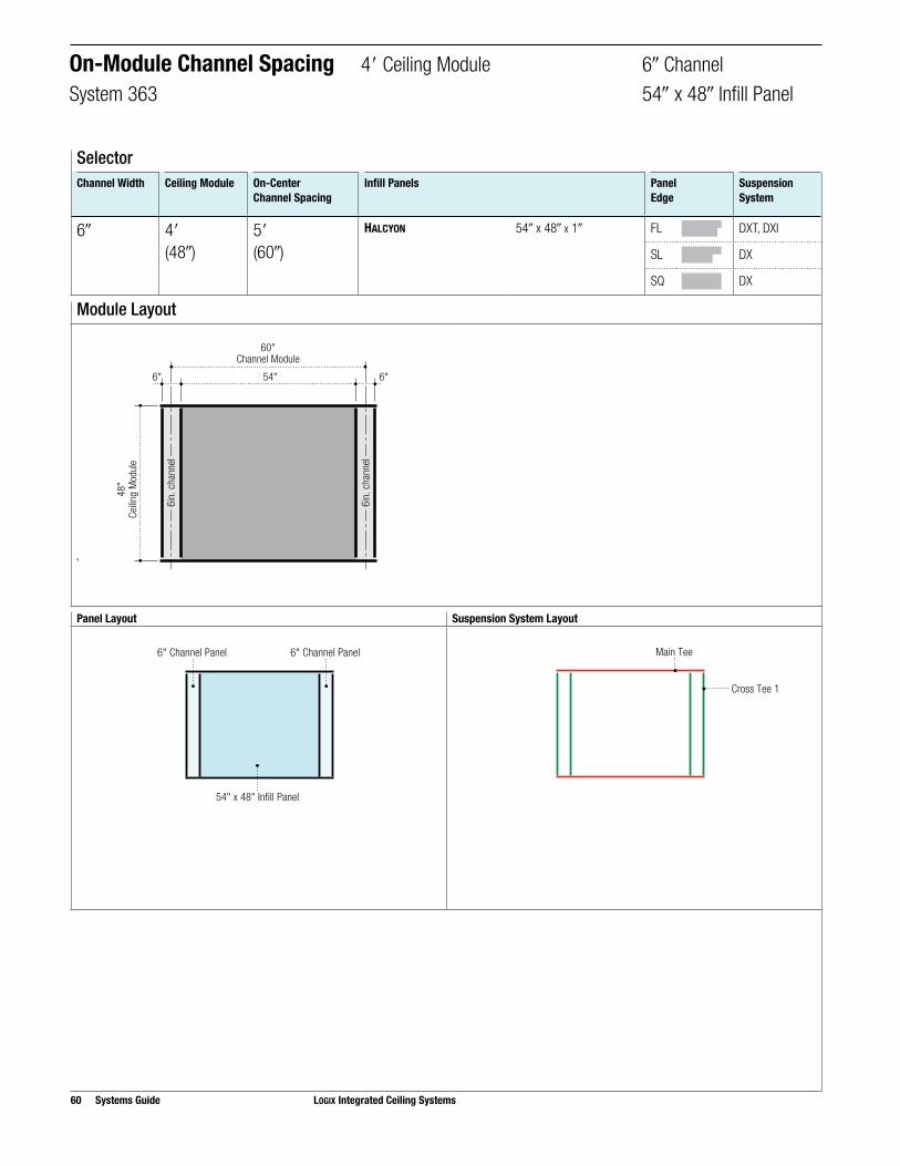
6! 4" 5" 54! x 48! • 363 60-61
6! 5" 5" 54! x 20! • 753 62-63
6! 5" 5" 27! x 30! • 856 64-65
6! 5" 5" 27! x 60! • 343 66-67
6! 5" 5" 54! x 30! • 865 68-69
6! 5" 12" 45! x 48! 48! x 48!
• 275 70-71

30 Systems Guide LOGIX Integrated Ceiling Systems
On-Module Channel Spacing
4" and 5" Ceiling Modules
Overview
Channel Width
Ceiling Module
On-Center Channel Spacing
Infill Panels PANZ Metal Option System Page
InfillPanel
ChannelPanel
12! Channel
12! 4" 5" 24! x 48! • • 944 72-73
12! 4" 5" 24! x 24! • • 464 74-75
12! 4" 5" 48! x 48! • 279 76-77
12! 5" 6" 30! x 60! • • 372 78-79
12! 5" 6" 30! x 30! • • 934 80-81
12! 5" 6" 60! x 20! • • 649 82-83
12! 6" 5" 24! x 48! • • 997 84-85
12! 6" 5" 24! x 24! • • 665 86-87
12! 6" 5" 24! x 72! • • 785 88-89
LOGIX Integrated Ceiling Systems Systems Guide 31
Channel Width
Ceiling Module
On-Center Channel Spacing
Infill Panels PANZ Metal Option System Page
InfillPanel
ChannelPanel
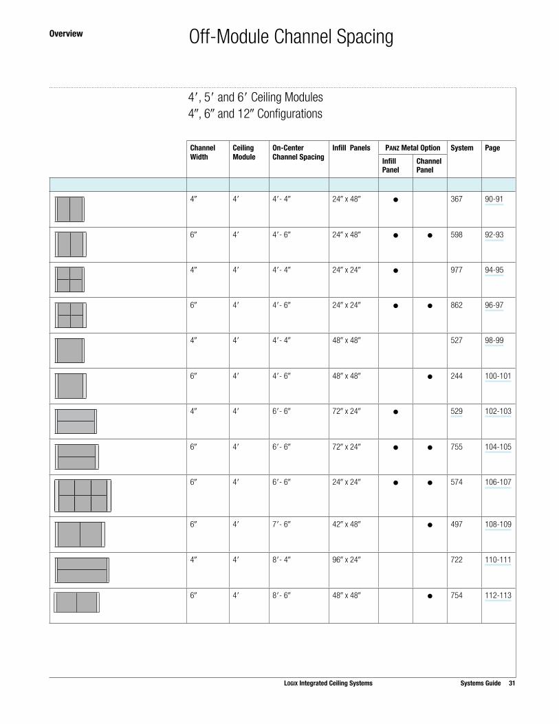
4! 4" 4"- 4! 24! x 48! • 367 90-91
6! 4" 4"- 6! 24! x 48! • • 598 92-93
4! 4" 4"- 4! 24! x 24! • 977 94-95
6! 4" 4"- 6! 24! x 24! • • 862 96-97
4! 4" 4"- 4! 48! x 48! 527 98-99
6! 4" 4"- 6! 48! x 48! • 244 100-101
4! 4" 6"- 6! 72! x 24! • 529 102-103
6! 4" 6"- 6! 72! x 24! • • 755 104-105
6! 4" 6"- 6! 24! x 24! • • 574 106-107
6! 4" 7"- 6! 42! x 48! • 497 108-109
4! 4" 8"- 4! 96! x 24! 722 110-111
6! 4" 8"- 6! 48! x 48! • 754 112-113
Off-Module Channel Spacing
4", 5" and 6" Ceiling Modules4!, 6! and 12! Configurations
Overview

32 Systems Guide LOGIX Integrated Ceiling Systems
Off-Module Channel Spacing
4", 5" and 6" Ceiling Modules4!, 6! and 12! Configurations
Overview
Channel Width
Ceiling Module
On-Center Channel Spacing
Infill Panels PANZ Metal Option System Page
InfillPanel
ChannelPanel
6! 4" 8"- 6! 96! x 24! • 664 114-115
6! 4" 8"- 6! 96! x 48! • 979 116-117
6! 4" 8"- 6! 24! x 24! • • 776 118-119
6! 4" 10"- 6! 120! x 24! • 383 120-121
4! 5" 5"- 4! 30! x 60! • 697 122-123
6! 5" 5"- 6! 30! x 60! • • 369 124-125
4! 5" 5"- 4! 30! x 30! • 378 126-127
6! 5" 5"- 6! 30! x 30! • • 642 128-129
4! 6" 4"- 4! 24! x 48! • • 859 130-131
6! 6" 4"- 6! 24! x 48! • • 824 132-133

LOGIX Integrated Ceiling Systems Systems Guide 33
Channel Width
Ceiling Module
On-Center Channel Spacing
Infill Panels PANZ Metal Option System Page
InfillPanel
ChannelPanel
6! 4" 8"- 6! 96! x 24! • 664 114-115
6! 4" 8"- 6! 96! x 48! • 979 116-117
6! 4" 8"- 6! 24! x 24! • • 776 118-119
6! 4" 10"- 6! 120! x 24! • 383 120-121
4! 5" 5"- 4! 30! x 60! • 697 122-123
6! 5" 5"- 6! 30! x 60! • • 369 124-125
4! 5" 5"- 4! 30! x 30! • 378 126-127
6! 5" 5"- 6! 30! x 30! • • 642 128-129
4! 6" 4"- 4! 24! x 48! • • 859 130-131
6! 6" 4"- 6! 24! x 48! • • 824 132-133
Channel Width
Ceiling Module
On-Center Channel Spacing
Infill Panels PANZ Metal Option System Page
InfillPanel
ChannelPanel
4! 6" 4"- 4! 24! x 24! • • 724 134-135
6! 6" 4"- 6! 24! x 24! • • 292 136-137
4! 6" 4"- 4! 24! x 72! • • 562 138-139
6! 6" 4"- 6! 24! x 72! • • 643 140-141
Off-Module Channel Spacing
4", 5" and 6" Ceiling Modules4!, 6! and 12! Configurations
Overview

34 Systems Guide LOGIX Integrated Ceiling Systems
SelectorChannel Width Ceiling Module On-Center
Channel SpacingInfill Panels Panel
EdgeSuspension System
4! 4"(48!)
4"(48!)
HALCYON 22! x 48! x 1! FL DXT, DXI
SL DX
SQ DX
MARS 22! x 48 x 3/4! FLB DXT, DXI
SLT DX
SQ DX
MARS High-NRC 22! x 48! x 7/8! FLB DXT, DXI
SLT DX
SQ DX
Panel Layout Suspension System Layout
22" x 48" Infill Panel
4" Channel Panel 4" Channel Panel
Cross Tee 1
Main Tee
Cross Tee 2
On-Module Channel Spacing 4" Ceiling Module 4! ChannelSystem 764 22! x 48! Infill Panel
Module Layout
22"4" 4"22"
48"Channel Module
48"
Ceilin
g M
odul
e
4in.
cha
nnel
4in.
cha
nnel

Step 3. Select Corresponding Grid for Selected Panels
FL/FLB SL/SLT SQ
Edge Item No. Edge Item No. Edge Item No.
Infill Panels HALCYON 22! x 48! x 1! FL ¨ 97468 SL ¨ 97441 SQ ¨ 97414
MARS 22! x 48! x 3/4! FLB ¨ 86575 SLT ¨ 86553 SQ ¨ 86525
MARS High-NRC 22! x 48! x 7/8! FLB ¨ 86486 SLT ¨ 86454 SQ ¨ 86417
Channel Panels HALCYON 4! x 48! x 1! FL ¨ 97460 SL ¨ 97430 SQ ¨ 97402
MARS 4! x 48! x 3/4! FLB ¨ 86568 SLT ¨ 86540 SQ ¨ 86514
MARS High-NRC 4! x 48! x 7/8! FLB ¨ 86475 SLT ¨ 86440 SQ ¨ 86402
Qty Item No. Qty Item No. Qty Item No.
Suspension Systems
CENTRICITEE DXT Main Tee ¨ DXT24SP101
Cross Tee 1 2 ¨ DXT424
Cross Tee 2 1 ¨ DXT424
IDENTITEE DXI Main Tee ¨ DXI24SP101
Cross Tee 1 2 ¨ DXI424
Cross Tee 2 1 ¨ DXI424
DONN DX Main Tee ¨ DX24SP101 ¨ DX24SP101
Cross Tee 1 2 ¨ DX422 2 ¨ DX422
Cross Tee 2 1 ¨ DX422 1 ¨ DX422
Order Information 4" Ceiling Module 4! ChannelSystem 764 22! x 48! Infill Panel
Suspension System EstimatorLength Sq. Ft. Main Tee
Usage Per Sq. Ft.Cross Tee 1Usage Per Sq. Ft.
Cross Tee 2Usage Per Sq. Ft.
System Module 48! 16 0.25 0.50 0.25
Note: Multiply the ceiling area (SF) by the Usage Factor (UF). This calculation will determine lineal footage of suspension system components required. Please refer to the front of this catalogue or IC592 for stabilizer bar usage.
LOGIX Integrated Ceiling Systems Systems Guide 35
Step 1. Select Panels Step 2. Select Edge for Panels

36 Systems Guide LOGIX Integrated Ceiling Systems
SelectorChannel Width Ceiling Module On-Center
Channel SpacingInfill Panels Panel
EdgeSuspension System
4! 4"(48!)
4"(48!)
HALCYON 22! x 24! x 1! FL DXT, DXI
SL DX
SQ DX, DXT
MARS 22! x 24! x 3/4! FLB DXT, DXI
SLT DX
SQ DX, DXT
MARS High-NRC 22! x 24! x 7/8! FLB DXT, DXI
SLT DX
SQ DX, DXT
Panel Layout Suspension System Layout
22" x 24" Infill Panel
4" Channel Panel 4" Channel Panel
Cross Tee 3 Main Tee
Cross Tee 1
Cross Tee 2
On-Module Channel Spacing 4" Ceiling Module 4! ChannelSystem 996 22! x 24! Infill Panel
Module Layout
24"
24"
22"4" 4"22"
48"Channel Module
48"
Ceilin
g M
odul
e
4in.
cha
nnel
4in.
cha
nnel

Step 3. Select Corresponding Grid for Selected Panels
FL/FLB SL/SLT SQ
Edge Item No. Edge Item No. Edge Item No.
Infill Panels HALCYON 22! x 24! x 1! FL ¨ 97467 SL ¨ 97440 SQ ¨ 97413
MARS 22! x 24! x 3/4! FLB ¨ 86574 SLT ¨ 86552 SQ ¨ 86524
MARS High-NRC 22! x 24! x 7/8! FLB ¨ 86485 SLT ¨ 86453 SQ ¨ 86416
Channel Panels HALCYON 4! x 48! x 1! FL ¨ 97460 SL ¨ 97430 SQ ¨ 97402
MARS 4! x 48! x 3/4! FLB ¨ 86568 SLT ¨ 86540 SQ ¨ 86514
MARS High-NRC 4! x 48! x 7/8! FLB ¨ 86475 SLT ¨ 86440 SQ ¨ 86402
Qty Item No. Qty Item No. Qty Item No.
Suspension Systems
CENTRICITEE DXT Main Tee ¨ DXT24SP101 ¨ DXT24SP101
Cross Tee 1 2 ¨ DXT424 2 ¨ DXT424
Cross Tee 2 1 ¨ DXT424 1 ¨ DXT424
Cross Tee 3 2 ¨ DXT2222 2 ¨ DXT2222
IDENTITEE DXI Main Tee ¨ DXI24SP101
Cross Tee 1 2 ¨ DXI424
Cross Tee 2 1 ¨ DXI424
Cross Tee 3 2 ¨ DXT2222
DONN DX Main Tee ¨ DX24SP101 ¨ DX24SP101
Cross Tee 1 2 ¨ DX422 2 ¨ DX422
Cross Tee 2 1 ¨ DX422 1 ¨ DX422
Cross Tee 3 2 ¨ DX2216 2 ¨ DX2216
Order Information 4" Ceiling Module 4! ChannelSystem 996 22! x 24! Infill Panel
Suspension System EstimatorLength Sq. Ft. Main Tee
Usage Per Sq. Ft.Cross Tee 1Usage Per Sq. Ft.
Cross Tee 2Usage Per Sq. Ft.
Cross Tee 3Usage Per Sq. Ft.
System Module 48! 16 0.25 0.50 0.25 0.23
Note: Multiply the ceiling area (SF) by the Usage Factor (UF). This calculation will determine lineal footage of suspension system components required. Please refer to the front of this catalogue or IC592 for stabilizer bar usage.
LOGIX Integrated Ceiling Systems Systems Guide 37
Step 1. Select Panels Step 2. Select Edge for Panels

38 Systems Guide LOGIX Integrated Ceiling Systems
SelectorChannel Width Ceiling Module On-Center
Channel SpacingInfill Panels Panel
EdgeSuspension System
4! 4"(48!)
4"(48!)
HALCYON 44! x 24! x 1! FL DXT, DXI
SL DX
SQ DX
MARS 44! x 24! x 3/4! FLB DXT, DXI
SLT DX
SQ DX
MARS High-NRC 44! x 24! x 7/8! FLB DXT, DXI
SLT DX
SQ DX
Panel Layout Suspension System Layout
44" x 24" Infill Panel
4" Channel Panel 4" Channel Panel
Cross Tee 1
Main TeeCross Tee 2
Module Layout
24"
24"
4" 4"44"
48"Channel Module
48"
Ceilin
g M
odul
e
4in.
cha
nnel
4in.
cha
nnel
On-Module Channel Spacing 4" Ceiling Module 4! ChannelSystem 952 44! x 24! Infill Panel
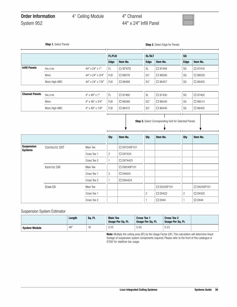
Suspension System EstimatorLength Sq. Ft. Main Tee
Usage Per Sq. Ft.Cross Tee 1Usage Per Sq. Ft.
Cross Tee 2Usage Per Sq. Ft.
System Module 48! 16 0.25 0.50 0.23
Note: Multiply the ceiling area (SF) by the Usage Factor (UF). This calculation will determine lineal footage of suspension system components required. Please refer to the front of this catalogue or IC592 for stabilizer bar usage.
Step 3. Select Corresponding Grid for Selected Panels
FL/FLB SL/SLT SQ
Edge Item No. Edge Item No. Edge Item No.
Infill Panels HALCYON 44! x 24! x 1! FL ¨ 97470 SL ¨ 97444 SQ ¨ 97416
MARS 44! x 24! x 3/4! FLB ¨ 86578 SLT ¨ 86556 SQ ¨ 86528
MARS High-NRC 44! x 24! x 7/8! FLB ¨ 86489 SLT ¨ 86457 SQ ¨ 86420
Channel Panels HALCYON 4! x 48! x 1! FL ¨ 97460 SL ¨ 97430 SQ ¨ 97402
MARS 4! x 48! x 3/4! FLB ¨ 86568 SLT ¨ 86540 SQ ¨ 86514
MARS High-NRC 4! x 48! x 7/8! FLB ¨ 86475 SLT ¨ 86440 SQ ¨ 86402
Qty Item No. Qty Item No. Qty Item No.
Suspension Systems
CENTRICITEE DXT Main Tee ¨ DXT24SP101
Cross Tee 1 2 ¨ DXT424
Cross Tee 2 1 ¨ DXT4422
IDENTITEE DXI Main Tee ¨ DXI24SP101
Cross Tee 1 2 ¨ DXI424
Cross Tee 2 1 ¨ DXI4424
DONN DX Main Tee ¨ DX24SP101 ¨ DX24SP101
Cross Tee 1 2 ¨ DX422 2 ¨ DX422
Cross Tee 2 1 ¨ DX44 1 ¨ DX44
Order Information 4" Ceiling Module 4! ChannelSystem 952 44! x 24! Infill Panel
LOGIX Integrated Ceiling Systems Systems Guide 39
Step 1. Select Panels Step 2. Select Edge for Panels

40 Systems Guide LOGIX Integrated Ceiling Systems
SelectorChannel Width Ceiling Module On-Center
Channel SpacingInfill Panels Panel
EdgeSuspension System
4! 4"(48!)
4"(48!)
HALCYON 44! x 48! x 1! FL DXT, DXI
SL DX
SQ DX
Panel Layout Suspension System Layout
44" x 48" Infill Panel
4" Channel Panel 4" Channel Panel
Cross Tee 1
Main Tee
Module Layout
4" 4"44"
48"Channel Module
48"
Ceilin
g M
odul
e
4in.
cha
nnel
4in.
cha
nnel
On-Module Channel Spacing 4" Ceiling Module 4! ChannelSystem 375 44! x 48! Infill Panel

Suspension System EstimatorLength Sq. Ft. Main Tee
Usage Per Sq. Ft.Cross Tee 1Usage Per Sq. Ft.
System Module 48! 16 0.25 0.50
Note: Multiply the ceiling area (SF) by the Usage Factor (UF). This calculation will determine lineal footage of suspension system components required. Please refer to the front of this catalogue or IC592 for stabilizer bar usage.
Step 3. Select Corresponding Grid for Selected Panels
FL/FLB SL/SLT SQ
Edge Item No. Edge Item No. Edge Item No.
Infill Panels HALCYON 44! x 48! x 1! FL ¨ 97475 SL ¨ 97455 SQ ¨ 97425
Channel Panels HALCYON 4! x 48! x 1! FL ¨ 97460 SL ¨ 97430 SQ ¨ 97402
Qty Item No. Qty Item No. Qty Item No.
Suspension Systems
CENTRICITEE DXT Main Tee ¨ DXT24SP101
Cross Tee 1 2 ¨ DXT424
IDENTITEE DXI Main Tee ¨ DXI24SP101
Cross Tee 1 2 ¨ DXI424
DONN DX Main Tee ¨ DX24SP101 ¨ DX24SP101
Cross Tee 1 2 ¨ DX422 2 ¨ DX422
Order Information 4" Ceiling Module 4! ChannelSystem 375 44! x 48! Infill Panel
LOGIX Integrated Ceiling Systems Systems Guide 41
Step 1. Select Panels Step 2. Select Edge for Panels

42 Systems Guide LOGIX Integrated Ceiling Systems
Panel Layout Suspension System Layout
56" x 20" Infill Panel
4" Channel Panel 4" Channel Panel
Cross Tee 1
Main TeeCross Tee 2
Module Layout
56"4" 4"
20"
20"
20"
60"Channel Module
60"
Ceilin
g M
odul
e
4in.
cha
nnel
4in.
cha
nnel
SelectorChannel Width Ceiling Module On-Center
Channel SpacingInfill Panels Panel
EdgeSuspension System
4! 5" (60!)
5"(60!)
HALCYON 56! x 20! x 1! FL DXT, DXI
SL DX
SQ DX
MARS 56! x 20! x 3/4! FLB DXT, DXI
SLT DX
SQ DX
MARS High-NRC 56! x 20! x 7/8! FLB DXT, DXI
SLT DX
SQ DX
On-Module Channel Spacing 5" Ceiling Module 4! ChannelSystem 537 56! x 20! Infill Panel

Suspension System EstimatorLength Sq. Ft. Main Tee
Usage Per Sq. Ft.Cross Tee 1Usage Per Sq. Ft.
Cross Tee 2Usage Per Sq. Ft.
System Module 60! 25 0.20 0.40 0.37
Note: Multiply the ceiling area (SF) by the Usage Factor (UF). This calculation will determine lineal footage of suspension system components required. Please refer to the front of this catalogue or IC592 for stabilizer bar usage.
Step 3. Select Corresponding Grid for Selected Panels
FL/FLB SL/SLT SQ
Edge Item No. Edge Item No. Edge Item No.
Infill Panels HALCYON 56! x 20! x 1! FL ¨ 97464 SL ¨ 97437 SQ ¨ 97408
MARS 56! x 20! x 3/4! FLB ¨ 86571 SLT ¨ 86548 SQ ¨ 86520
MARS High-NRC 56! x 20! x 7/8! FLB ¨ 86480 SLT ¨ 86448 SQ ¨ 86411
Channel Panels HALCYON 4! x 60! x 1! FL ¨ 97461 SL ¨ 97431 SQ ¨ 97403
MARS 4! x 60! x 3/4! FLB ¨ 86569 SLT ¨ 86541 SQ ¨ 86515
MARS High-NRC 4! x 60! x 7/8! FLB ¨ 86476 SLT ¨ 86441 SQ ¨ 86403
Qty Item No. Qty Item No. Qty Item No.
Suspension Systems
CENTRICITEE DXT Main Tee ¨ DXT24SP102
Cross Tee 1 2 ¨ DXT524
Cross Tee 2 2 ¨ DXT5622
IDENTITEE DXI Main Tee ¨ DXI24SP102
Cross Tee 1 2 ¨ DXI524
Cross Tee 2 2 ¨ DXI5624
DONN DX Main Tee ¨ DX24SP102 ¨ DX24SP102
Cross Tee 1 2 ¨ DX524 2 ¨ DX524
Cross Tee 2 2 ¨ DX5616 2 ¨ DX5616
Order Information 5" Ceiling Module 4! ChannelSystem 537 56! x 20! Infill Panel
LOGIX Integrated Ceiling Systems Systems Guide 43
Step 1. Select Panels Step 2. Select Edge for Panels
44 Systems Guide LOGIX Integrated Ceiling Systems
Panel Layout Suspension System Layout
4" Channel Panel 4" Channel Panel
28" x 30" Infill Panel
Cross Tee 1
Main TeeCross Tee 3
Cross Tee 2
Module Layout
28"4" 4"28"
30"
30"
60"Channel Module
60"
Ceilin
g M
odul
e
4in.
cha
nnel
4in.
cha
nnel
SelectorChannel Width Ceiling Module On-Center
Channel SpacingInfill Panels Panel
EdgeSuspension System
4! 5"(60!)
5"(60!)
HALCYON 28! x 30! x 1! FL DXT, DXI
SL DX
SQ DX
MARS 28! x 30! x 3/4! FLB DXT, DXI
SLT DX
SQ DX
MARS High-NRC 28! x 30! x 7/8! FLB DXT, DXI
SLT DX
SQ DX
On-Module Channel Spacing 5" Ceiling Module 4! ChannelSystem 339 28! x 30! Infill Panel

Suspension System EstimatorLength Sq. Ft. Main Tee
Usage Per Sq. Ft.Cross Tee 1Usage Per Sq. Ft.
Cross Tee 2Usage Per Sq. Ft.
Cross Tee 3Usage Per Sq. Ft.
System Module 60! 25 0.20 0.40 0.20 0.19
Note: Multiply the ceiling area (SF) by the Usage Factor (UF). This calculation will determine lineal footage of suspension system components required. Please refer to the front of this catalogue or IC592 for stabilizer bar usage.
Step 3. Select Corresponding Grid for Selected Panels
FL/FLB SL/SLT SQ
Edge Item No. Edge Item No. Edge Item No.
Infill Panels HALCYON 28! x 30! x 1! FL ¨ 97335 SL ¨ 97449 SQ ¨ 97419
MARS 28! x 30! x 3/4! FLB ¨ 86834 SLT ¨ 86559 SQ ¨ 86532
MARS High-NRC 28! x 30! x 7/8! FLB ¨ 86492 SLT ¨ 86459 SQ ¨ 86423
Channel Panels HALCYON 4! x 60! x 1! FL ¨ 97461 SL ¨ 97431 SQ ¨ 97403
MARS 4! x 60! x 3/4! FLB ¨ 86569 SLT ¨ 86541 SQ ¨ 86515
MARS High-NRC 4! x 60! x 7/8! FLB ¨ 86476 SLT ¨ 86441 SQ ¨ 86403
Qty Item No. Qty Item No. Qty Item No.
Suspension Systems
CENTRICITEE DXT Main Tee ¨ DXT24SP102
Cross Tee 1 2 ¨ DXT524
Cross Tee 2 1 ¨ DXT524
Cross Tee 3 2 ¨ DXT2822
IDENTITEE DXI Main Tee ¨ DXI24SP102
Cross Tee 1 2 ¨ DXI524
Cross Tee 2 1 ¨ DXI524
Cross Tee 3 2 ¨ DXT2822
DONN DX Main Tee ¨ DX24SP102 ¨ DX24SP102
Cross Tee 1 2 ¨ DX524 2 ¨ DX524
Cross Tee 2 1 ¨ DX524 1 ¨ DX524
Cross Tee 3 2 ¨ DX2816 2 ¨ DX2816
Order Information 5" Ceiling Module 4! ChannelSystem 339 28! x 30! Infill Panel
LOGIX Integrated Ceiling Systems Systems Guide 45
Step 1. Select Panels Step 2. Select Edge for Panels

46 Systems Guide LOGIX Integrated Ceiling Systems
Panel Layout Suspension System Layout
28" x 60" Infill Panel
4" Channel Panel 4" Channel Panel
Cross Tee 1
Main Tee
Cross Tee 2
Module Layout
28"4" 4"28"
60"Channel Module
60"
Ceilin
g M
odul
e
4in.
cha
nnel
4in.
cha
nnel
SelectorChannel Width Ceiling Module On-Center
Channel SpacingInfill Panels Panel
EdgeSuspension System
4! 5"(60!)
5"(60!)
HALCYON 28! x 60! x 1! FL DXT, DXI
SL DX
SQ DX
MARS 28! x 60! x 3/4! FLB DXT, DXI
SLT DX
SQ DX
MARS High-NRC 28! x 60! x 7/8! FLB DXT, DXI
SLT DX
SQ DX
On-Module Channel Spacing 5" Ceiling Module 4! ChannelSystem 433 28! x 60! Infill Panel

Suspension System EstimatorLength Sq. Ft. Main Tee
Usage Per Sq. Ft.Cross Tee 1Usage Per Sq. Ft.
Cross Tee 2Usage Per Sq. Ft.
System Module 60! 25 0.20 0.40 0.20
Note: Multiply the ceiling area (SF) by the Usage Factor (UF). This calculation will determine lineal footage of suspension system components required. Please refer to the front of this catalogue or IC592 for stabilizer bar usage.
Step 3. Select Corresponding Grid for Selected Panels
FL/FLB SL/SLT SQ
Edge Item No. Edge Item No. Edge Item No.
Infill Panels HALCYON 28! x 60! x 1! FL ¨ 97355 SL ¨ 97450 SQ ¨ 97420
MARS 28! x 60! x 3/4! FLB ¨ 86580 SLT ¨ 86560 SQ ¨ 86533
MARS High-NRC 28! x 60! x 7/8! FLB ¨ 86493 SLT ¨ 86461 SQ ¨ 86424
Channel Panels HALCYON 4! x 60! x 1! FL ¨ 97461 SL ¨ 97431 SQ ¨ 97403
MARS 4! x 60! x 3/4! FLB ¨ 86569 SLT ¨ 86541 SQ ¨ 86515
MARS High-NRC 4! x 60! x 7/8! FLB ¨ 86476 SLT ¨ 86441 SQ ¨ 86403
Qty Item No. Qty Item No. Qty Item No.
Suspension Systems
CENTRICITEE DXT Main Tee ¨ DXT24SP102
Cross Tee 1 2 ¨ DXT524
Cross Tee 2 1 ¨ DXT524
IDENTITEE DXI Main Tee ¨ DXI24SP102
Cross Tee 1 2 ¨ DXI524
Cross Tee 2 1 ¨ DXI524
DONN DX Main Tee ¨ DX24SP102 ¨ DX24SP102
Cross Tee 1 2 ¨ DX524 2 ¨ DX524
Cross Tee 2 1 ¨ DX524 1 ¨ DX524
Order Information 5" Ceiling Module 4! ChannelSystem 433 28! x 60! Infill Panel
LOGIX Integrated Ceiling Systems Systems Guide 47
Step 1. Select Panels Step 2. Select Edge for Panels

48 Systems Guide LOGIX Integrated Ceiling Systems
Panel Layout Suspension System Layout
4" Channel Panel 4" Channel Panel
56" x 30" Infill Panel
Cross Tee 1
Main TeeCross Tee 2
Module Layout
56"4" 4"
30"
30"
60"Channel Module
60"
Ceilin
g M
odul
e
4in.
cha
nnel
4in.
cha
nnel
On-Module Channel Spacing 4" Ceiling Module 4! ChannelSystem 524 56! x 30! Infill Panel
SelectorChannel Width Ceiling Module On-Center
Channel SpacingInfill Panels Panel
EdgeSuspension System
4! 5"(60!)
5"(60!)
HALCYON 56! x 30! x 1! FL DXT, DXI
SL DX
SQ DX
MARS 56! x 30! x 3/4! FLB DXT, DXI
SLT DX
SQ DX
MARS High-NRC 56! x 30! x 7/8! FLB DXT, DXI
SLT DX
SQ DX

Suspension System EstimatorLength Sq. Ft. Main Tee
Usage Per Sq. Ft.Cross Tee 1Usage Per Sq. Ft.
Cross Tee 2Usage Per Sq. Ft.
System Module 60! 25 0.20 0.40 0.19
Note: Multiply the ceiling area (SF) by the Usage Factor (UF). This calculation will determine lineal footage of suspension system components required. Please refer to the front of this catalogue or IC592 for stabilizer bar usage.
Step 3. Select Corresponding Grid for Selected Panels
FL/FLB SL/SLT SQ
Edge Item No. Edge Item No. Edge Item No.
Infill Panels HALCYON 56! x 30! x 1! FL ¨ 97473 SL ¨ 97453 SQ ¨ 97423
MARS 56! x 30! x 3/4! FLB ¨ 86583 SLT ¨ 86563 SQ ¨ 86535
MARS High-NRC 56! x 30! x 7/8! FLB ¨ 86496 SLT ¨ 86465 SQ ¨ 86428
Channel Panels HALCYON 4! x 60! x 1! FL ¨ 97461 SL ¨ 97431 SQ ¨ 97403
MARS 4! x 60! x 3/4! FLB ¨ 86569 SLT ¨ 86541 SQ ¨ 86515
MARS High-NRC 4! x 60! x 7/8! FLB ¨ 86476 SLT ¨ 86441 SQ ¨ 86403
Qty Item No. Qty Item No. Qty Item No.
Suspension Systems
CENTRICITEE DXT Main Tee ¨ DXT24SP102
Cross Tee 1 2 ¨ DXT524
Cross Tee 2 1 ¨ DXT5622
IDENTITEE DXI Main Tee ¨ DXI24SP102
Cross Tee 1 2 ¨ DXI524
Cross Tee 2 1 ¨ DXI5624
DONN DX Main Tee ¨ DX24SP102 ¨ DX24SP102
Cross Tee 1 2 ¨ DX524 2 ¨ DX524
Cross Tee 2 1 ¨ DX5616 1 ¨ DX5616
Order Information 5" Ceiling Module 4! ChannelSystem 524 56! x 30! Infill Panel
LOGIX Integrated Ceiling Systems Systems Guide 49
Step 1. Select Panels Step 2. Select Edge for Panels
50 Systems Guide LOGIX Integrated Ceiling Systems
Panel Layout
46" x 48" Infill Panel 48" x 48" Infill Panel 46" x 48" Infill Panel
4" Channel Panel 4" Channel Panel
Suspension System Layout
Cross Tee 1
Main Tee
Cross Tee 2
Module Layout
46" 46"48"4" 4"
144"Channel Module
48"
Ceilin
g M
odul
e
4in.
cha
nnel
4in.
cha
nnel
SelectorChannel Width Ceiling Module On-Center
Channel SpacingInfill Panels Panel
EdgeSuspension System
4! 4"(48!)
12"(144!)
HALCYON 46! x 48! x 1!48! x 48! x 1!
FL DXT, DXI
SL DX
SQ DX
On-Module Channel Spacing 4" Ceiling Module 4! ChannelSystem 795 46! x 48! Infill Panel 48! x 48! Infill Panel

Suspension System EstimatorLength Sq. Ft. Main Tee
Usage Per Sq. Ft.Cross Tee 1Usage Per Sq. Ft.
Cross Tee 2Usage Per Sq. Ft.
System Module 144! 48 0.25 0.17 0.17
Note: Multiply the ceiling area (SF) by the Usage Factor (UF). This calculation will determine lineal footage of suspension system components required. Please refer to the front of this catalogue or IC592 for stabilizer bar usage.
Step 3. Select Corresponding Grid for Selected Panels
FL/FLB SL/SLT SQ
Edge Item No. Edge Item No. Edge Item No.
Infill Panels HALCYON 46! x 48! x 1! FL ¨ 97477 SL ¨ 97457 SQ ¨ 97427
Channel Panels HALCYON 4! x 48! x 1! FL ¨ 97460 SL ¨ 97430 SQ ¨ 97402
Qty Item No. Qty Item No. Qty Item No.
Suspension Systems
CENTRICITEE DXT Main Tee ¨ DXT24SP104
Cross Tee 1 2 ¨ DXT424
Cross Tee 2 2 ¨ DXT424
IDENTITEE DXI Main Tee ¨ DXI24SP104
Cross Tee 1 2 ¨ DXI424
Cross Tee 2 2 ¨ DXI424
DONN DX Main Tee ¨ DX24SP104 ¨ DX24SP104
Cross Tee 1 2 ¨ DX422 2 ¨ DX422
Cross Tee 2 2 ¨ DX422 2 ¨ DX422
Order Information 4" Ceiling Module 4! ChannelSystem 795 46! x 48! Infill Panel 48! x 48! Infill Panel
LOGIX Integrated Ceiling Systems Systems Guide 51
Step 1. Select Panels Step 2. Select Edge for Panels

52 Systems Guide LOGIX Integrated Ceiling Systems
Panel Layout Suspension System Layout
6" Channel Panel 6" Channel Panel
42" x 48" Infill Panel
Main Tee
Cross Tee 1
Module Layout
42"6" 6"
48"Channel Module
48"
Ceilin
g M
odul
e
6in.
cha
nnel
6in.
cha
nnel
On-Module Channel Spacing 4" Ceiling Module 6! ChannelSystem 346 42! x 48! Infill Panel
SelectorChannel Width Ceiling Module On-Center
Channel SpacingInfill Panels Panel
EdgeSuspension System
6! 4"(48!)
4"(48!)
HALCYON 42! x 48! x 1! FL DXT, DXI
SL DX
SQ DX

Suspension System EstimatorLength Sq. Ft. Main Tee
Usage Per Sq. Ft.Cross Tee 1Usage Per Sq. Ft.
System Module 48! 16 0.25 0.50
Note: Multiply the ceiling area (SF) by the Usage Factor (UF). This calculation will determine lineal footage of suspension system components required. Please refer to the front of this catalogue or IC592 for stabilizer bar usage.
FL/FLB SL/SLT SQ
Edge Item No. Edge Item No. Edge Item No.
Infill Panels HALCYON 42! x 48! x 1! FL ¨ 98343 SL ¨ 97454 SQ ¨ 97424
Channel Panels HALCYON 6! x 48! x 1! FL ¨ 98198 SL ¨ 99271 SQ ¨ 97227
PANZ Metal Panels, Solid 6! x 48! FL ¨ 256820 SL ¨ 256819 SQ ¨ 256768
Panz Metal Panels, Perf C116 6! x 48! FL ¨ 256062 SL ¨ 257248 SQ ¨ 256397
Panz Metal Panels, Perf C116D 6! x 48! FL ¨ 257585 SL ¨ 257584 SQ ¨ 257406
Qty Item No. Qty Item No. Qty Item No.
Suspension Systems
CENTRICITEE DXT Main Tee ¨ DXT24
Cross Tee 1 2 ¨ DXT424
IDENTITEE DXI Main Tee ¨ DXI24
Cross Tee 1 2 ¨ DXI424
DONN DX Main Tee ¨ DX/DXL24 ¨ DX/DXL24
Cross Tee 1 2 ¨ DX422 2 ¨ DX422
Order Information 4" Ceiling Module 6! ChannelSystem 346 42! x 48! Infill Panel
Step 3. Select Corresponding Grid for Selected Panels
LOGIX Integrated Ceiling Systems Systems Guide 53
Step 1. Select Panels Step 2. Select Edge for Panels

54 Systems Guide LOGIX Integrated Ceiling Systems
Panel Layout Suspension System Layout
6" Channel Panel 6" Channel Panel
42" x 24" Infill Panel
Cross Tee 1
Main TeeCross Tee 2
Module Layout
24"
24"
42"6" 6"
48"Channel Module
48"
Ceilin
g M
odul
e
6in.
cha
nnel
6in.
cha
nnel
SelectorChannel Width Ceiling Module On-Center
Channel SpacingInfill Panels Panel
EdgeSuspension System
6! 4"(60!)
4"(60!)
HALCYON 42! x 24! x 1! FL DXT, DXI
SL DX
SQ DX
MARS 42! x 24 x 3/4! FLB DXT, DXI
SLT DX
SQ DX
MARS High-NRC 42! x 24! x 7/8! FLB DXT, DXI
SLT DX
SQ DX
On-Module Channel Spacing 4" Ceiling Module 6! ChannelSystem 727 42! x 24! Infill Panel

Suspension System EstimatorLength Sq. Ft. Main Tee
Usage Per Sq. Ft.Cross Tee 1Usage Per Sq. Ft.
Cross Tee 2Usage Per Sq. Ft.
System Module 48! 16 0.25 0.50 0.22
Note: Multiply the ceiling area (SF) by the Usage Factor (UF). This calculation will determine lineal footage of suspension system components required. Please refer to the front of this catalogue or IC592 for stabilizer bar usage.
FL/FLB SL/SLT SQ
Edge Item No. Edge Item No. Edge Item No.
Infill Panels HALCYON 42! x 24! x 1! FL ¨ 98196 SL ¨ 97443 SQ ¨ 97277
MARS 42! x 24! x 3/4! FLB ¨ 86577 SLT ¨ 86555 SQ ¨ 86527
MARS High-NRC 42! x 24! x 7/8! FLB ¨ 86488 SLT ¨ 86456 SQ ¨ 86419
Channel Panels HALCYON 6! x 48! x 1! FL ¨ 98198 SL ¨ 99271 SQ ¨ 97227
MARS 6! x 48! x 3/4! FLB ¨ 88887 SLT ¨ 86542 SQ ¨ 86325
MARS High-NRC 6! x 48! x 7/8! FLB ¨ 86331 SLT ¨ 86442 SQ ¨ 86404
PANZ Metal Panels, Solid 6! x 48! FL ¨ 256820 SL ¨ 256819 SQ ¨ 256768
Panz Metal Panels, Perf C116 6! x 48! FL ¨ 256062 SL ¨ 257248 SQ ¨ 256397
Panz Metal Panels, Perf C116D 6! x 48! FL ¨ 257585 SL ¨ 257584 SQ ¨ 257406
Qty Item No. Qty Item No. Qty Item No.
Suspension Systems
CENTRICITEE DXT Main Tee ¨ DXT24
Cross Tee 1 2 ¨ DXT424
Cross Tee 2 1 ¨ DXT4224
IDENTITEE DXI Main Tee ¨ DXI24
Cross Tee 1 2 ¨ DXI424
Cross Tee 2 1 ¨ DXI4224
DONN DX Main Tee ¨ DX/DXL24 ¨ DX/DXL24
Cross Tee 1 2 ¨ DX422 2 ¨ DX422
Cross Tee 2 1 ¨ DX4224 1 ¨ DX4224
Order Information 4" Ceiling Module 6! ChannelSystem 727 42! x 24! Infill Panel
Step 3. Select Corresponding Grid for Selected Panels
LOGIX Integrated Ceiling Systems Systems Guide 55
Step 1. Select Panels Step 2. Select Edge for Panels

56 Systems Guide LOGIX Integrated Ceiling Systems
Panel Layout Suspension System Layout
6" Channel Panel 6" Channel Panel
21" x 24" Infill Panel
Cross Tee 1
Main TeeCross Tee 3
Cross Tee 2
Module Layout
24"
24"
21"6" 6"21"
48"Channel Module
48"
Ceilin
g M
odul
e
6in.
cha
nnel
6in.
cha
nnel
SelectorChannel Width Ceiling Module On-Center
Channel SpacingInfill Panels Panel
EdgeSuspension System
6! 4"(48!)
4"(48!)
HALCYON 21! x 24! x 1! FL DXT, DXI
SL DX
SQ DX, DXT
MARS 21! x 24! x 3/4! FLB DXT, DXI
SLT DX
SQ DX, DXT
MARS High-NRC 21! x 24! x 7/8! FLB DXT, DXI
SLT DX
SQ DX, DXT
On-Module Channel Spacing 4" Ceiling Module 6! ChannelSystem 838 21! x 24! Infill Panel

Suspension System EstimatorLength Sq. Ft. Main Tee
Usage Per Sq. Ft.Cross Tee 1Usage Per Sq. Ft.
Cross Tee 2Usage Per Sq. Ft.
Cross Tee 3Usage Per Sq. Ft.
System Module 48! 16 0.25 0.50 0.25 0.22
Note: Multiply the ceiling area (SF) by the Usage Factor (UF). This calculation will determine lineal footage of suspension system components required. Please refer to the front of this catalogue or IC592 for stabilizer bar usage.
FL/FLB SL/SLT SQ
Edge Item No. Edge Item No. Edge Item No.
Infill Panels HALCYON 21! x 24! x 1! FL ¨ 98195 SL ¨ 98220 SQ ¨ 97411
MARS 21! x 24! x 3/4! FLB ¨ 88840 SLT ¨ 86550 SQ ¨ 86522
MARS High-NRC 21! x 24! x 7/8! FLB ¨ 86483 SLT ¨ 86451 SQ ¨ 86414
Channel Panels HALCYON 6! x 48! x 1! FL ¨ 98198 SL ¨ 99271 SQ ¨ 97227
MARS 6! x 48! x 3/4! FLB ¨ 88887 SLT ¨ 86542 SQ ¨ 86325
MARS High-NRC 6! x 48! x 7/8! FLB ¨ 86331 SLT ¨ 86442 SQ ¨ 86404
PANZ Metal Panels, Solid 6! x 48! FL ¨ 256820 SL ¨ 256819 SQ ¨ 256768
Panz Metal Panels, Perf C116 6! x 48! FL ¨ 256062 SL ¨ 257248 SQ ¨ 256397
Panz Metal Panels, Perf C116D 6! x 48! FL ¨ 257585 SL ¨ 257584 SQ ¨ 257406
Qty Item No. Qty Item No. Qty Item No.
Suspension Systems
CENTRICITEE DXT Main Tee ¨ DXT24SP105 ¨ DXT24SP105
Cross Tee 1 2 ¨ DXT424 2 ¨ DXT424
Cross Tee 2 1 ¨ DXT424 1 ¨ DXT424
Cross Tee 3 2 ¨ DXT2122 2 ¨ DXT2122
IDENTITEE DXI Main Tee ¨ DXI24SP105
Cross Tee 1 2 ¨ DXI424
Cross Tee 2 1 ¨ DXI424
Cross Tee 3 2 ¨ DXI2122
DONN DX Main Tee ¨ DX24SP105 ¨ DX24SP105
Cross Tee 1 2 ¨ DX422 2 ¨ DX422
Cross Tee 2 1 ¨ DX422 1 ¨ DX
Cross Tee 3 2 ¨ DX2116 2 ¨ DX2116
Order Information 4" Ceiling Module 6! ChannelSystem 838 21! x 24! Infill Panel
Step 3. Select Corresponding Grid for Selected Panels
LOGIX Integrated Ceiling Systems Systems Guide 57
Step 1. Select Panels Step 2. Select Edge for Panels

58 Systems Guide LOGIX Integrated Ceiling Systems
SelectorChannel Width Ceiling Module On-Center
Channel SpacingInfill Panels Panel
EdgeSuspension System
4! 4"(48!)
4"(48!)
HALCYON 21! x 48! x 1! FL DXT, DXI
SL DX
SQ DX
MARS 21! x 48 x 3/4! FLB DXT, DXI
SLT DX
SQ DX
MARS High-NRC 21! x 48! x 7/8! FLB DXT, DXI
SLT DX
SQ DX
Panel Layout Suspension System Layout
6" Channel Panel 6" Channel Panel
21" x 48" Infill Panel
Cross Tee 1
Main Tee
Cross Tee 2
Module Layout
21"6" 6"21"
48"Channel Module
48"
Ceilin
g M
odul
e
6in.
cha
nnel
6in.
cha
nnel
`
On-Module Channel Spacing 4" Ceiling Module 6! ChannelSystem 646 21! x 48! Infill Panel

Suspension System EstimatorLength Sq. Ft. Main Tee
Usage Per Sq. Ft.Cross Tee 1Usage Per Sq. Ft.
Cross Tee 2Usage Per Sq. Ft.
System Module 48! 16 0.25 0.50 0.25
Note: Multiply the ceiling area (SF) by the Usage Factor (UF). This calculation will determine lineal footage of suspension system components required. Please refer to the front of this catalogue or IC592 for stabilizer bar usage.
FL/FLB SL/SLT SQ
Edge Item No. Edge Item No. Edge Item No.
Infill Panels HALCYON 21! x 48! x 1! FL ¨ 97466 SL ¨ 97439 SQ ¨ 97412
MARS 21! x 48! x 3/4! FLB ¨ 86573 SLT ¨ 86551 SQ ¨ 86523
MARS High-NRC 21! x 48! x 7/8! FLB ¨ 86484 SLT ¨ 86452 SQ ¨ 86415
Channel Panels HALCYON 6! x 48! x 1! FL ¨ 98198 SL ¨ 99271 SQ ¨ 97227
MARS 6! x 48! x 3/4! FLB ¨ 88887 SLT ¨ 86542 SQ ¨ 86325
MARS High-NRC 6! x 48! x 7/8! FLB ¨ 86331 SLT ¨ 86442 SQ ¨ 86404
PANZ Metal Panels, Solid 6! x 48! FL ¨ 256820 SL ¨ 256819 SQ ¨ 256768
Panz Metal Panels, Perf C116 6! x 48! FL ¨ 256062 SL ¨ 257248 SQ ¨ 256397
Panz Metal Panels, Perf C116D 6! x 48! FL ¨ 257585 SL ¨ 257584 SQ ¨ 257406
Qty Item No. Qty Item No. Qty Item No.
Suspension Systems
CENTRICITEE DXT Main Tee ¨ DXT24SP105
Cross Tee 1 2 ¨ DXT424
Cross Tee 2 1 ¨ DXT424
IDENTITEE DXI Main Tee ¨ DXI24SP105
Cross Tee 1 2 ¨ DXI424
Cross Tee 2 1 ¨ DXI424
DONN DX Main Tee ¨ DX24SP105 ¨ DX24SP105
Cross Tee 1 2 ¨ DX422 2 ¨ DX422
Cross Tee 2 1 ¨ DX422 1 ¨ DX422
Order Information 4" Ceiling Module 6! ChannelSystem 646 21! x 48! Infill Panel
Step 3. Select Corresponding Grid for Selected Panels
LOGIX Integrated Ceiling Systems Systems Guide 59
Step 1. Select Panels Step 2. Select Edge for Panels
60 Systems Guide LOGIX Integrated Ceiling Systems
Panel Layout Suspension System Layout
6" Channel Panel 6" Channel Panel
54" x 48" Infill Panel
Cross Tee 1
Main Tee
Module Layout
`
54"6" 6"
60"Channel Module
48"
Ceilin
g M
odul
e
6in.
cha
nnel
6in.
cha
nnel
SelectorChannel Width Ceiling Module On-Center
Channel SpacingInfill Panels Panel
EdgeSuspension System
6! 4"(48!)
5"(60!)
HALCYON 54! x 48! x 1! FL DXT, DXI
SL DX
SQ DX
On-Module Channel Spacing 4" Ceiling Module 6! ChannelSystem 363 54! x 48! Infill Panel

Suspension System EstimatorLength Sq. Ft. Main Tee
Usage Per Sq. Ft.Cross Tee 1Usage Per Sq. Ft.
System Module 60! 20 0.25 0.40
Note: Multiply the ceiling area (SF) by the Usage Factor (UF). This calculation will determine lineal footage of suspension system components required. Please refer to the front of this catalogue or IC592 for stabilizer bar usage.
Step 3. Select Corresponding Grid for Selected Panels
FL/FLB SL/SLT SQ
Edge Item No. Edge Item No. Edge Item No.
Infill Panels HALCYON 54! x 48! x 1! FL ¨ 98344 SL ¨ 97458 SQ ¨ 97428
Channel Panels HALCYON 6! x 48! x 1! FL ¨ 98198 SL ¨ 99271 SQ ¨ 97227
PANZ Metal Panels, Solid 6! x 48! FL ¨ 256820 SL ¨ 256819 SQ ¨ 256768
Panz Metal Panels, Perf C116 6! x 48! FL ¨ 256062 SL ¨ 257248 SQ ¨ 256397
Panz Metal Panels, Perf C116D 6! x 48! FL ¨ 257585 SL ¨ 257584 SQ ¨ 257406
Qty Item No. Qty Item No. Qty Item No.
Suspension Systems
CENTRICITEE DXT Main Tee ¨ DXT24
Cross Tee 1 2 ¨ DXT424
IDENTITEE DXI Main Tee ¨ DXI24
Cross Tee 1 2 ¨ DXI424
DONN DX Main Tee ¨ DX/DXL24 ¨ DX/DXL24
Cross Tee 1 2 ¨ DX422 2 ¨ DX422
Order Information 4" Ceiling Module 6! ChannelSystem 363 54! x 48! Infill Panel
LOGIX Integrated Ceiling Systems Systems Guide 61
Step 1. Select Panels Step 2. Select Edge for Panels

62 Systems Guide LOGIX Integrated Ceiling Systems
Panel Layout Suspension System Layout
6" Channel Panel 6" Channel Panel
54" x 20" Infill Panel
Cross Tee 1
Main TeeCross Tee 2
Module Layout
54"6" 6"
20"
20"
20"
60"Channel Module
60"
Ceilin
g M
odul
e
6in.
cha
nnel
6in.
cha
nnel
SelectorChannel Width Ceiling Module On-Center
Channel SpacingInfill Panels Panel
EdgeSuspension System
6! 5"(60!)
5"(60!)
HALCYON 54! x 20! x 1! FL DXT, DXI
SL DX
SQ DX
MARS 54! x 20! x 3/4! FLB DXT, DXI
SLT DX
SQ DX
MARS High-NRC 54! x 20! x 7/8! FLB DXT, DXI
SLT DX
SQ DX
On-Module Channel Spacing 5" Ceiling Module 6! ChannelSystem 753 54! x 20! Infill Panel

Suspension System EstimatorLength Sq. Ft. Main Tee
Usage Per Sq. Ft.Cross Tee 1Usage Per Sq. Ft.
System Module 609 20 0.25 0.40
Note: Multiply the ceiling area (SF) by the Usage Factor (UF). This calculation will determine lineal footage of suspension system components required. Please refer to the front of this catalogue or IC592 for stabilizer bar usage.
FL/FLB SL/SLT SQ
Edge Item No. Edge Item No. Edge Item No.
Infill Panels Halcyon 549 x 209 x 19 FL ¨ 98360 SL ¨ 97436 SQ ¨ 97407
Mars 549 x 209 x 3/49 FLB ¨ 88845 SLT ¨ 86547 SQ ¨ 86519
Mars High-NRC 549 x 209 x 7/89 FLB ¨ 86479 SLT ¨ 86447 SQ ¨ 86410
Channel Panels Halcyon 69 x 609 x 19 FL ¨ 98199 SL ¨ 99272 SQ ¨ 97228
Mars 69 x 609 x 3/49 FLB ¨ 86835 SLT ¨ 86543 SQ ¨ 86507
Mars High-NRC 69 x 609 x 7/89 FLB ¨ 86333 SLT ¨ 86443 SQ ¨ 86145
Panz Metal Panels, Solid 69 x 609 FL ¨ 258036 SL ¨ 257972 SQ ¨ 257586
Panz Metal Panels, Perf C116 69 x 609 FL ¨ 259228 SL ¨ 259010 SQ ¨ 259009
Panz Metal Panels, Perf C116D 69 x 609 FL ¨ 259353 SL ¨ 259344 SQ ¨ 259308
Qty Item No. Qty Item No. Qty Item No.
Suspension Systems
centricitee DXt Main Tee ¨ DXT24
Cross Tee 1 2 ¨ DXT524
Cross Tee 2 2 ¨ DXT5424
iDentitee DXI Main Tee ¨ DXI24
Cross Tee 1 2 ¨ DXI524
Cross Tee 2 2 ¨ DXI5424
Donn DX Main Tee ¨ DX/DXL24 ¨ DX/DXL24
Cross Tee 1 2 ¨ DX524 2 ¨ DX524
Cross Tee 2 2 ¨ DX5424 2 ¨ DX5424
Order Information 58 Ceiling Module 69 ChannelSystem 753 549 x 209 Infill Panel
Step 3. Select Corresponding Grid for Selected Panels
Logix Integrated Ceiling Systems Systems Guide 63
Step 1. Select Panels Step 2. Select Edge for Panels

64 Systems Guide LOGIX Integrated Ceiling Systems
Panel Layout Suspension System Layout
6" Channel Panel 6" Channel Panel
27" x 30" Infill Panel
Cross Tee 1
Main TeeCross Tee 3
Cross Tee 2
Module Layout
27"6" 6"27"
30"
30"
60"Channel Module
60"
Ceilin
g M
odul
e
6in.
cha
nnel
6in.
cha
nnel
SelectorChannel Width Ceiling Module On-Center
Channel SpacingInfill Panels Panel
EdgeSuspension System
6! 5"(60!)
5"(60!)
HALCYON 27! x 30! x 1! FL DXT, DXI
SL DX
SQ DX
MARS 27! x 30! x 3/4! FLB DXT, DXI
SLT DX
SQ DX
MARS High-NRC 27! x 30! x 7/8! FLB DXT, DXI
SLT DX
SQ DX
On-Module Channel Spacing 5" Ceiling Module 6! ChannelSystem 856 27! x 30! Infill Panel

Suspension System EstimatorLength Sq. Ft. Main Tee
Usage Per Sq. Ft.Cross Tee 1Usage Per Sq. Ft.
Cross Tee 2Usage Per Sq. Ft.
Cross Tee 3Usage Per Sq. Ft.
System Module 60! 25 0.20 0.40 0.20 0.18
Note: Multiply the ceiling area (SF) by the Usage Factor (UF). This calculation will determine lineal footage of suspension system components required. Please refer to the front of this catalogue or IC592 for stabilizer bar usage.
FL/FLB SL/SLT SQ
Edge Item No. Edge Item No. Edge Item No.
Infill Panels HALCYON 27! x 30! x 1! FL ¨ 97333 SL ¨ 97477 SQ ¨ 97417
MARS 27! x 30! x 3/4! FLB ¨ 86850 SLT ¨ 86557 SQ ¨ 86530
MARS High-NRC 27! x 30! x 7/8! FLB ¨ 86490 SLT ¨ 86458 SQ ¨ 86421
Channel Panels HALCYON 6! x 60! x 1! FL ¨ 98199 SL ¨ 99272 SQ ¨ 97228
MARS 6! x 60! x 3/4! FLB ¨ 86835 SLT ¨ 86543 SQ ¨ 86507
MARS High-NRC 6! x 60! x 7/8! FLB ¨ 86333 SLT ¨ 86443 SQ ¨ 86145
PANZ Metal Panels, Solid 6! x 60! FL ¨ 258036 SL ¨ 257972 SQ ¨ 257586
Panz Metal Panels, Perf C116 6! x 60! FL ¨ 259228 SL ¨ 259010 SQ ¨ 259009
Panz Metal Panels, Perf C116D 6! x 60! FL ¨ 259353 SL ¨ 259344 SQ ¨ 259308
Qty Item No. Qty Item No. Qty Item No.
Suspension Systems
CENTRICITEE DXT Main Tee ¨ DXT24SP109
Cross Tee 1 2 ¨ DXT524
Cross Tee 2 1 ¨ DXT524
Cross Tee 3 2 ¨ DXT2722
IDENTITEE DXI Main Tee ¨ DXI24SP109
Cross Tee 1 2 ¨ DXI524
Cross Tee 2 1 ¨ DXI524
Cross Tee 3 2 ¨ DXI2724
DONN DX Main Tee ¨ DX24SP109 ¨ DX24SP109
Cross Tee 1 2 ¨ DX524 2 ¨ DX524
Cross Tee 2 1 ¨ DX524 1 ¨ DX524
Cross Tee 3 2 ¨ DX2716 2 ¨ DX2716
Order Information 5" Ceiling Module 6! ChannelSystem 856 27! x 30! Infill Panel
Step 3. Select Corresponding Grid for Selected Panels
LOGIX Integrated Ceiling Systems Systems Guide 65
Step 1. Select Panels Step 2. Select Edge for Panels

66 Systems Guide LOGIX Integrated Ceiling Systems
Panel Layout Suspension System Layout
27" x 60" Infill Panel
6" Channel Panel 6" Channel Panel
Cross Tee 1
Main Tee
Cross Tee 2
Module Layout
27"6" 6"27"
60"Channel Module
60"
Ceilin
g M
odul
e
6in.
cha
nnel
6in.
cha
nnel
SelectorChannel Width Ceiling Module On-Center
Channel SpacingInfill Panels Panel
EdgeSuspension System
6! 5"(60!)
5"(60!)
HALCYON 27! x 60! x 1! FL DXT, DXI
SL DX
SQ DX
MARS 27! x 60! x 3/4! FLB DXT, DXI
SLT DX
SQ DX
MARS High-NRC 27! x 60! x 7/8! FLB DXT, DXI
SLT DX
SQ DX
On-Module Channel Spacing 5" Ceiling Module 6! ChannelSystem 343 27! x 60! Infill Panel

Suspension System EstimatorLength Sq. Ft. Main Tee
Usage Per Sq. Ft.Cross Tee 1Usage Per Sq. Ft.
Cross Tee 2Usage Per Sq. Ft.
System Module 60! 25 0.20 0.40 0.20
Note: Multiply the ceiling area (SF) by the Usage Factor (UF). This calculation will determine lineal footage of suspension system components required. Please refer to the front of this catalogue or IC592 for stabilizer bar usage.
FL/FLB SL/SLT SQ
Edge Item No. Edge Item No. Edge Item No.
Infill Panels HALCYON 27! x 60! x 1! FL ¨ 98440 SL ¨ 97448 SQ ¨ 97418
MARS 27! x 60! x 3/4! FLB ¨ 86579 SLT ¨ 86558 SQ ¨ 86531
MARS High-NRC 27! x 60! x 7/8! FLB ¨ 86491 SLT ¨ 86460 SQ ¨ 86422
Channel Panels HALCYON 6! x 60! x 1! FL ¨ 98199 SL ¨ 99272 SQ ¨ 97228
MARS 6! x 60! x 3/4! FLB ¨ 86835 SLT ¨ 86543 SQ ¨ 86507
MARS High-NRC 6! x 60! x 7/8! FLB ¨ 86333 SLT ¨ 86443 SQ ¨ 86145
PANZ Metal Panels, Solid 6! x 60! FL ¨ 258036 SL ¨ 257972 SQ ¨ 257586
Panz Metal Panels, Perf C116 6! x 60! FL ¨ 259228 SL ¨ 259010 SQ ¨ 259009
Panz Metal Panels, Perf C116D 6! x 60! FL ¨ 259353 SL ¨ 259344 SQ ¨ 259308
Qty Item No. Qty Item No. Qty Item No.
Suspension Systems
CENTRICITEE DXT Main Tee ¨ DXT24SP109
Cross Tee 1 2 ¨ DXT524
Cross Tee 2 1 ¨ DXT524
IDENTITEE DXI Main Tee ¨ DXI24SP109
Cross Tee 1 2 ¨ DXI524
Cross Tee 2 1 ¨ DXI524
DONN DX Main Tee ¨ DX24SP109 ¨ DX24SP109
Cross Tee 1 2 ¨ DX524 2 ¨ DX524
Cross Tee 2 1 ¨ DX524 1 ¨ DX524
Order Information 5" Ceiling Module 6! ChannelSystem 343 27! x 60! Infill Panel
Step 3. Select Corresponding Grid for Selected Panels
LOGIX Integrated Ceiling Systems Systems Guide 67
Step 1. Select Panels Step 2. Select Edge for Panels

68 Systems Guide LOGIX Integrated Ceiling Systems
Panel Layout Suspension System Layout
54" x 30" Infill Panel
6" Channel Panel 6" Channel Panel
Cross Tee 1
Main TeeCross Tee 2
Module Layout
54"6" 6"
30"
30"
60"Channel Module
60"
Ceilin
g M
odul
e
6in.
cha
nnel
6in.
cha
nnel
SelectorChannel Width Ceiling Module On-Center
Channel SpacingInfill Panels Panel
EdgeSuspension System
6! 5"(60!)
5"(60!)
HALCYON 54! x 30! x 1! FL DXT, DXI
SL DX
SQ DX
MARS 54! x 30! x 3/4! FLB DXT, DXI
SLT DX
SQ DX
MARS High-NRC 54! x 30! x 7/8! FLB DXT, DXI
SLT DX
SQ DX
On-Module Channel Spacing 4" Ceiling Module 4! ChannelSystem 865 54! x 30! Infill Panel

Suspension System EstimatorLength Sq. Ft. Main Tee
Usage Per Sq. Ft.Cross Tee 1Usage Per Sq. Ft.
Cross Tee 2Usage Per Sq. Ft.
System Module 60! 25 0.20 0.40 0.18
Note: Multiply the ceiling area (SF) by the Usage Factor (UF). This calculation will determine lineal footage of suspension system components required. Please refer to the front of this catalogue or IC592 for stabilizer bar usage.
FL/FLB SL/SLT SQ
Edge Item No. Edge Item No. Edge Item No.
Infill Panels HALCYON 54! x 30! x 1! FL ¨ 98359 SL ¨ 98337 SQ ¨ 97422
MARS 54! x 30! x 3/4! FLB ¨ 86831 SLT ¨ 88686 SQ ¨ 86503
MARS High-NRC 54! x 30! x 7/8! FLB ¨ 86501 SLT ¨ 86464 SQ ¨ 86427
Channel Panels HALCYON 6! x 60! x 1! FL ¨ 98199 SL ¨ 99272 SQ ¨ 97228
MARS 6! x 60! x 3/4! FLB ¨ 86835 SLT ¨ 86543 SQ ¨ 86507
MARS High-NRC 6! x 60! x 7/8! FLB ¨ 86333 SLT ¨ 86443 SQ ¨ 86145
PANZ Metal Panels, Solid 6! x 60! FL ¨ 258036 SL ¨ 257972 SQ ¨ 257586
Panz Metal Panels, Perf C116 6! x 60! FL ¨ 259228 SL ¨ 259010 SQ ¨ 259009
Panz Metal Panels, Perf C116D 6! x 60! FL ¨ 259353 SL ¨ 259344 SQ ¨ 259308
Qty Item No. Qty Item No. Qty Item No.
Suspension Systems
CENTRICITEE DXT Main Tee ¨ DXT24
Cross Tee 1 2 ¨ DXT524
Cross Tee 2 1 ¨ DXT5424
IDENTITEE DXI Main Tee ¨ DXI24
Cross Tee 1 2 ¨ DXI524
Cross Tee 2 1 ¨ DXI5424
DONN DX Main Tee ¨ DX/DXL24 ¨ DX/DXL24
Cross Tee 1 2 ¨ DX524 2 ¨ DX524
Cross Tee 2 1 ¨ DX5416 1 ¨ DX5416
Order Information 5" Ceiling Module 6! ChannelSystem 865 54! x 30! Infill Panel
Step 3. Select Corresponding Grid for Selected Panels
LOGIX Integrated Ceiling Systems Systems Guide 69
Step 1. Select Panels Step 2. Select Edge for Panels

70 Systems Guide LOGIX Integrated Ceiling Systems
Panel Layout
45" x 48" Infill Panel
6" Channel Panel 6" Channel Panel
48" x 48" Infill Panel 45" x 48" Infill Panel
Module Layout
45"6" 6"48" 45"
144"Channel Module
48"
Ceilin
g M
odul
e
6in.
cha
nnel
6in.
cha
nnel
SelectorChannel Width Ceiling Module On-Center
Channel SpacingInfill Panels Panel
EdgeSuspension System
6! 4"(48!)
12"(144!)
HALCYON 45! x 48! x 1!48! x 48! x 1!
FL DXT, DXI
SL DX
SQ DX
On-Module Channel Spacing 4" Ceiling Module 6! ChannelSystem 275 45! x 48! Infill Panel 48! x 48! Infill Panel
Suspension System Layout
Cross Tee 1
Main Tee
Cross Tee 2
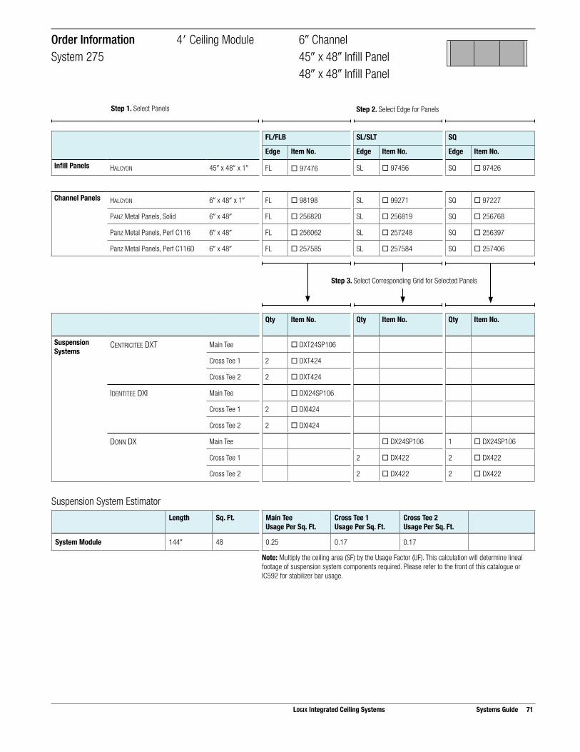
Suspension System EstimatorLength Sq. Ft. Main Tee
Usage Per Sq. Ft.Cross Tee 1Usage Per Sq. Ft.
Cross Tee 2Usage Per Sq. Ft.
System Module 144! 48 0.25 0.17 0.17
Note: Multiply the ceiling area (SF) by the Usage Factor (UF). This calculation will determine lineal footage of suspension system components required. Please refer to the front of this catalogue or IC592 for stabilizer bar usage.
FL/FLB SL/SLT SQ
Edge Item No. Edge Item No. Edge Item No.
Infill Panels HALCYON 45! x 48! x 1! FL ¨ 97476 SL ¨ 97456 SQ ¨ 97426
Channel Panels HALCYON 6! x 48! x 1! FL ¨ 98198 SL ¨ 99271 SQ ¨ 97227
PANZ Metal Panels, Solid 6! x 48! FL ¨ 256820 SL ¨ 256819 SQ ¨ 256768
Panz Metal Panels, Perf C116 6! x 48! FL ¨ 256062 SL ¨ 257248 SQ ¨ 256397
Panz Metal Panels, Perf C116D 6! x 48! FL ¨ 257585 SL ¨ 257584 SQ ¨ 257406
Qty Item No. Qty Item No. Qty Item No.
Suspension Systems
CENTRICITEE DXT Main Tee ¨ DXT24SP106
Cross Tee 1 2 ¨ DXT424
Cross Tee 2 2 ¨ DXT424
IDENTITEE DXI Main Tee ¨ DXI24SP106
Cross Tee 1 2 ¨ DXI424
Cross Tee 2 2 ¨ DXI424
DONN DX Main Tee ¨ DX24SP106 1 ¨ DX24SP106
Cross Tee 1 2 ¨ DX422 2 ¨ DX422
Cross Tee 2 2 ¨ DX422 2 ¨ DX422
Order Information 4" Ceiling Module 6! ChannelSystem 275 45! x 48! Infill Panel 48! x 48! Infill Panel
Step 3. Select Corresponding Grid for Selected Panels
LOGIX Integrated Ceiling Systems Systems Guide 71
Step 1. Select Panels Step 2. Select Edge for Panels

72 Systems Guide LOGIX Integrated Ceiling Systems
Panel Layout Suspension System Layout
12" Channel Panel 12" Channel Panel
24" x 48" Infill Panel
Cross Tee 1
Main Tee
Cross Tee 2
Module Layout
24"12" 12"24"
60"Channel Module
48"
Ceilin
g M
odul
e
12in
. cha
nnel
12in
. cha
nnel
SelectorChannel Width Ceiling Module On-Center
Channel SpacingInfill Panels Panel
EdgeSuspension System
12! 4"(48!)
5"(60!)
HALCYON 24! x 48! x 1! FL DXT, DXI
SL DX
SQ DX
MARS 24! x 48 x 3/4! FLB DXT, DXI
SLT DX
SQ DX
MARS High-NRC 24! x 48! x 7/8! FLB DXT, DXI
SLT DX
SQ DX
PANZ Metal Panels, Solid 24! x 48! FL DXT, DXI
On-Module Channel Spacing 4" Ceiling Module 12! ChannelSystem 944 24! x 48! Infill Panel

Suspension System EstimatorLength Sq. Ft. Main Tee
Usage Per Sq. Ft.Cross Tee 1Usage Per Sq. Ft.
Cross Tee 2Usage Per Sq. Ft.
System Module 60! 20 0.25 0.40 0.20
Note: Multiply the ceiling area (SF) by the Usage Factor (UF). This calculation will determine lineal footage of suspension system components required. Please refer to the front of this catalogue or IC592 for stabilizer bar usage.
FL/FLB SL/SLT SQ
Edge Item No. Edge Item No. Edge Item No.
Infill Panels HALCYON 24! x 48! x 1! FL ¨ 98245 SL ¨ 98243 SQ ¨ 98241
MARS 24! x 48! x 3/4! FLB ¨ 88985 SLT ¨ 88785 SQ ¨ 88185
MARS High-NRC 24! x 48! x 7/8! FLB ¨ 89500 SLT ¨ 89600 SQ ¨ 86300
PANZ Metal Panels, Solid 24! x 48! FL ¨ 212164
Channel Panels HALCYON 12! x 48! x 1! FL ¨ 97575 SL ¨ 97571 SQ ¨ 97491
MARS 12! x 48! x 3/4! FLB ¨ 86321 SLT ¨ 86544 SQ ¨ 86516
MARS High-NRC 12! x 48! x 7/8! FLB ¨ 86505 SLT ¨ 86444 SQ ¨ 86407
PANZ Metal Panels, Solid 12! x 48 FL ¨ 212144
Qty Item No. Qty Item No. Qty Item No.
Suspension Systems
CENTRICITEE DXT Main Tee ¨ DXT24
Cross Tee 1 2 ¨ DXT424
Cross Tee 2 1 ¨ DXT424
IDENTITEE DXI Main Tee ¨ DXI24
Cross Tee 1 2 ¨ DXI424
Cross Tee 2 1 ¨ DXI424
DONN DX Main Tee ¨ DX/DXL24 ¨ DX/DXL24
Cross Tee 1 2 ¨ DX422 2 ¨ DX422
Cross Tee 2 1 ¨ DX422 1 ¨ DX422
Order Information 4" Ceiling Module 12! ChannelSystem 944 24! x 48! Infill Panel
Step 3. Select Corresponding Grid for Selected Panels
LOGIX Integrated Ceiling Systems Systems Guide 73
Step 1. Select Panels Step 2. Select Edge for Panels

74 Systems Guide LOGIX Integrated Ceiling Systems
Panel Layout Suspension System Layout
12" Channel Panel 12" Channel Panel
24" x 24" Infill Panel
Cross Tee 1
Main TeeCross Tee 3
Cross Tee 2
Module Layout
24"
24"
24"12" 12"24"
60"Channel Module
48"
Ceilin
g M
odul
e
12in
. cha
nnel
12in
. cha
nnel
SelectorChannel Width Ceiling Module On-Center
Channel SpacingInfill Panels Panel
EdgeSuspension System
12! 4"(48!)
5"(60!)
HALCYON 24! x 24! x 1! FL DXT, DXI
SL DX
SQ DX, DXT
MARS 24! x 24 x 3/4! FLB DXT, DXI
SLT DX
SQ DX, DXT
MARS High-NRC 24! x 24! x 7/8! FLB DXT, DXI
SLT DX
SQ DX, DXT
PANZ Metal Panels, Solid 24! x 24! FL DXT, DXI
On-Module Channel Spacing 4" Ceiling Module 12! ChannelSystem 464 24! x 24! Infill Panel
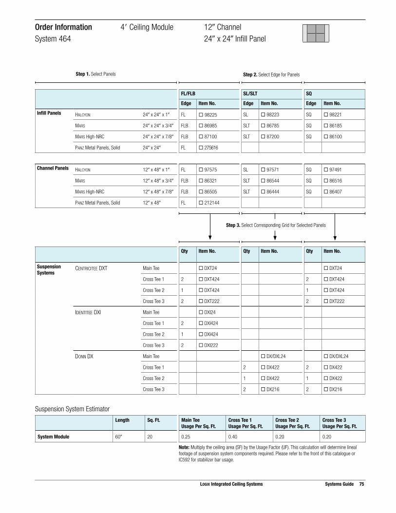
Suspension System EstimatorLength Sq. Ft. Main Tee
Usage Per Sq. Ft.Cross Tee 1Usage Per Sq. Ft.
Cross Tee 2Usage Per Sq. Ft.
Cross Tee 3Usage Per Sq. Ft.
System Module 60! 20 0.25 0.40 0.20 0.20
Note: Multiply the ceiling area (SF) by the Usage Factor (UF). This calculation will determine lineal footage of suspension system components required. Please refer to the front of this catalogue or IC592 for stabilizer bar usage.
FL/FLB SL/SLT SQ
Edge Item No. Edge Item No. Edge Item No.
Infill Panels HALCYON 24! x 24! x 1! FL ¨ 98225 SL ¨ 98223 SQ ¨ 98221
MARS 24! x 24! x 3/4! FLB ¨ 86985 SLT ¨ 86785 SQ ¨ 86185
MARS High-NRC 24! x 24! x 7/8! FLB ¨ 87100 SLT ¨ 87200 SQ ¨ 86100
PANZ Metal Panels, Solid 24! x 24! FL ¨ 275616
Channel Panels HALCYON 12! x 48! x 1! FL ¨ 97575 SL ¨ 97571 SQ ¨ 97491
MARS 12! x 48! x 3/4! FLB ¨ 86321 SLT ¨ 86544 SQ ¨ 86516
MARS High-NRC 12! x 48! x 7/8! FLB ¨ 86505 SLT ¨ 86444 SQ ¨ 86407
PANZ Metal Panels, Solid 12! x 48! FL ¨ 212144
Qty Item No. Qty Item No. Qty Item No.
Suspension Systems
CENTRICITEE DXT Main Tee ¨ DXT24 ¨ DXT24
Cross Tee 1 2 ¨ DXT424 2 ¨ DXT424
Cross Tee 2 1 ¨ DXT424 1 ¨ DXT424
Cross Tee 3 2 ¨ DXT222 2 ¨ DXT222
IDENTITEE DXI Main Tee ¨ DXI24
Cross Tee 1 2 ¨ DXI424
Cross Tee 2 1 ¨ DXI424
Cross Tee 3 2 ¨ DXI222
DONN DX Main Tee ¨ DX/DXL24 ¨ DX/DXL24
Cross Tee 1 2 ¨ DX422 2 ¨ DX422
Cross Tee 2 1 ¨ DX422 1 ¨ DX422
Cross Tee 3 2 ¨ DX216 2 ¨ DX216
Order Information 4" Ceiling Module 12! ChannelSystem 464 24! x 24! Infill Panel
Step 3. Select Corresponding Grid for Selected Panels
LOGIX Integrated Ceiling Systems Systems Guide 75
Step 1. Select Panels Step 2. Select Edge for Panels

76 Systems Guide LOGIX Integrated Ceiling Systems
Panel Layout Suspension System Layout
12" Channel Panel 12" Channel Panel
48" x 48" Infill Panel
Cross Tee 1
Main Tee
Module Layout
48"12" 12"
60"Channel Module
48"
Ceilin
g M
odul
e
12in
. cha
nnel
12in
. cha
nnel
SelectorChannel Width Ceiling Module On-Center
Channel SpacingInfill Panels Panel
EdgeSuspension System
12! 4"(48!)
5"(60!)
HALCYON 48! x 48! x 1! FL DXT, DXI
SL DX
SQ DX
On-Module Channel Spacing 4" Ceiling Module 12! ChannelSystem 279 48! x 48! Infill Panel

Suspension System EstimatorLength Sq. Ft. Main Tee
Usage Per Sq. Ft.Cross Tee 1Usage Per Sq. Ft.
System Module 60! 20 0.25 0.40
Note: Multiply the ceiling area (SF) by the Usage Factor (UF). This calculation will determine lineal footage of suspension system components required. Please refer to the front of this catalogue or IC592 for stabilizer bar usage.
FL/FLB SL/SLT SQ
Edge Item No. Edge Item No. Edge Item No.
Infill Panels HALCYON 48! x 48! x 1! FL ¨ 98445 SL ¨ 98443 SQ ¨ 98441
Channel Panels HALCYON 12! x 48! x 1! FL ¨ 97575 SL ¨ 97571 SQ ¨ 97491
PANZ Metal Panels, Solid 12! x 48! FL ¨ 212144
Qty Item No. Qty Item No. Qty Item No.
Suspension Systems
CENTRICITEE DXT Main Tee ¨ DXT24
Cross Tee 1 2 ¨ DXT424
IDENTITEE DXI Main Tee ¨ DXI24
Cross Tee 1 2 ¨ DXI424
DONN DX Main Tee ¨ DX/DXL24 ¨ DX/DXL24
Cross Tee 1 2 ¨ DX422 2 ¨ DX422
Order Information 4" Ceiling Module 12! ChannelSystem 279 48! x 48! Infill Panel
Step 3. Select Corresponding Grid for Selected Panels
LOGIX Integrated Ceiling Systems Systems Guide 77
Step 1. Select Panels Step 2. Select Edge for Panels

78 Systems Guide LOGIX Integrated Ceiling Systems
Panel Layout Suspension System Layout
12" Channel Panel 12" Channel Panel
30" x 60" Infill Panel
Cross Tee 1
Main Tee
Module Layout
30"12" 12"30"
72"Channel Module
60"
Ceilin
g M
odul
e
12in
. cha
nnel
12in
. cha
nnel
SelectorChannel Width Ceiling Module On-Center
Channel SpacingInfill Panels Panel
EdgeSuspension System
12! 5"(60!)
6"(72!)
HALCYON 30! x 60! x 1! FL DXT, DXI
SL DX
SQ DX
MARS 30! x 60! x 3/4! FLB DXT, DXI
SLT DX
SQ DX
MARS High-NRC 30! x 60! x 7/8! FLB DXT, DXI
SLT DX
SQ DX
PANZ Metal Panels, Solid 30! x 60! FL DXT, DXI
On-Module Channel Spacing 5" Ceiling Module 12! ChannelSystem 372 30! x 60! Infill Panel

Suspension System EstimatorLength Sq. Ft. Main Tee
Usage Per Sq. Ft.Cross Tee 1Usage Per Sq. Ft.
Cross Tee 2Usage Per Sq. Ft.
System Module 72! 30 0.20 0.33 0.17
Note: Multiply the ceiling area (SF) by the Usage Factor (UF). This calculation will determine lineal footage of suspension system components required. Please refer to the front of this catalogue or IC592 for stabilizer bar usage.
FL/FLB SL/SLT SQ
Edge Item No. Edge Item No. Edge Item No.
Infill Panels HALCYON 30! x 60! x 1! FL ¨ 98336 SL ¨ 99270 SQ ¨ 97266
MARS 30! x 60! x 3/4! FLB ¨ 86267 SLT ¨ 86564 SQ ¨ 86536
MARS High-NRC 30! x 60! x 7/8! FLB ¨ 86497 SLT ¨ 86466 SQ ¨ 86429
PANZ Metal Panels, Solid 30! x 60! FL ¨ 212201
Channel Panels HALCYON 12! x 60! x 1! FL ¨ 97576 SL ¨ 97434 SQ ¨ 97492
MARS 12! x 60! x 3/4! FLB ¨ 88885 SLT ¨ 86545 SQ ¨ 86517
MARS High-NRC 12! x 60! x 7/8! FLB ¨ 86477 SLT ¨ 86445 SQ ¨ 86408
PANZ Metal Panels, Solid 12! x 60! FL ¨ 212160
Qty Item No. Qty Item No. Qty Item No.
Suspension Systems
CENTRICITEE DXT Main Tee ¨ DXT24
Cross Tee 1 2 ¨ DXT524
IDENTITEE DXI Main Tee ¨ DXI24
Cross Tee 1 2 ¨ DXI524
DONN DX Main Tee ¨ DX/DXL24 ¨ DX/DXL24
Cross Tee 1 2 ¨ DX524 2 ¨ DX524
Order Information 5" Ceiling Module 12! ChannelSystem 372 30! x 60! Infill Panel
Step 3. Select Corresponding Grid for Selected Panels
LOGIX Integrated Ceiling Systems Systems Guide 79
Step 1. Select Panels Step 2. Select Edge for Panels

80 Systems Guide LOGIX Integrated Ceiling Systems
Panel Layout Suspension System Layout
30" x 30" Infill Panel
12" Channel Panel 12" Channel Panel
Cross Tee 1
Main TeeCross Tee 2
Module Layout
30"12" 12"30"
30"
30"
72"Channel Module
60"
Ceilin
g M
odul
e
12in
. cha
nnel
12in
. cha
nnel
SelectorChannel Width Ceiling Module On-Center
Channel SpacingInfill Panels Panel
EdgeSuspension System
12! 5"(60!)
6"(72!)
HALCYON 30! x 30! x 1! FL DXT, DXI
SL DX
SQ DX
MARS 30! x 30! x 3/4! FLB DXT, DXI
SLT DX
SQ DX
MARS High-NRC 30! x 30! x 7/8! FLB DXT, DXI
SLT DX
SQ DX
PANZ Metal Panels, Solid 30! x 30! FL DXT, DXI
On-Module Channel Spacing 5" Ceiling Module 12! ChannelSystem 934 30! x 30! Infill Panel

Suspension System EstimatorLength Sq. Ft. Main Tee
Usage Per Sq. Ft.Cross Tee 1Usage Per Sq. Ft.
Cross Tee 2Usage Per Sq. Ft.
Cross Tee 3Usage Per Sq. Ft.
System Module 729 30 0.20 0.33 0.17 0.17
Note: Multiply the ceiling area (SF) by the Usage Factor (UF). This calculation will determine lineal footage of suspension system components required. Please refer to the front of this catalogue or IC592 for stabilizer bar usage.
FL/FLB SL/SLT SQ
Edge Item No. Edge Item No. Edge Item No.
Infill Panels HALCYON 30! x 30! x 1! FL ¨ 98335 SL ¨ 98333 SQ ¨ 98331
MARS 30! x 30! x 3/4! FLB ¨ 86830 SLT ¨ 86875 SQ ¨ 86815
MARS High-NRC 30! x 30! x 7/8! FLB ¨ 86400 SLT ¨ 86500 SQ ¨ 86426
PANZ Metal Panels, Solid 30! x 30! FL ¨ 212123
Channel Panels HALCYON 12! x 60! x 1! FL ¨ 97576 SL ¨ 97434 SQ ¨ 97492
MARS 12! x 60! x 3/4! FLB ¨ 88885 SLT ¨ 86545 SQ ¨ 86517
MARS High-NRC 12! x 60! x 7/8! FLB ¨ 86477 SLT ¨ 86445 SQ ¨ 86408
PANZ Metal Panels, Solid 12! x 60! FL ¨ 212160
Qty Item No. Qty Item No. Qty Item No.
Suspension Systems
CENTRICITEE DXT Main Tee ¨ DXT24
Cross Tee 1 2 ¨ DXT524
Cross Tee 2 2 ¨ DXT3022
IDENTITEE DXI Main Tee ¨ DXI24
Cross Tee 1 2 ¨ DXI524
Cross Tee 2 2 ¨ DXI3022
DONN DX Main Tee ¨ DX/DXL24 ¨ DX/DXL24
Cross Tee 1 2 ¨ DX524 2 ¨ DX524
Cross Tee 2 2 ¨ DX3016 2 ¨ DX3016
Order Information 5" Ceiling Module 12! ChannelSystem 934 30! x 30! Infill Panel
Step 3. Select Corresponding Grid for Selected Panels
LOGIX Integrated Ceiling Systems Systems Guide 81
Step 1. Select Panels Step 2. Select Edge for Panels

82 Systems Guide LOGIX Integrated Ceiling Systems
Panel Layout Suspension System Layout
12" Channel Panel 12" Channel Panel
20" x 60" Infill Panel
Cross Tee 1
Main TeeCross Tee 2
Module Layout
60"12" 12"
20"
20"
20"
72"Channel Module
60"
Ceilin
g M
odul
e
12in
. cha
nnel
12in
. cha
nnel
SelectorChannel Width Ceiling Module On-Center
Channel SpacingInfill Panels Panel
EdgeSuspension System
12! 5"(60!)
6"(72!)
HALCYON 60! x 20! x 1! FL DXT, DXI
SL DX
SQ DX
MARS 60! x 20! x 3/4! FLB DXT, DXI
SLT DX
SQ DX
MARS High-NRC 60! x 20! x 7/8! FLB DXT, DXI
SLT DX
SQ DX
PANZ Metal Panels, Solid 60! x 20! FL DXT, DXI
On-Module Channel Spacing 5" Ceiling Module 12! ChannelSystem 649 60! x 20! Infill Panel

Suspension System EstimatorLength Sq. Ft. Main Tee
Usage Per Sq. Ft.Cross Tee 1Usage Per Sq. Ft.
Cross Tee 2Usage Per Sq. Ft.
System Module 72! 30 0.20 0.33 0.33
Note: Multiply the ceiling area (SF) by the Usage Factor (UF). This calculation will determine lineal footage of suspension system components required. Please refer to the front of this catalogue or IC592 for stabilizer bar usage.
FL/FLB SL/SLT SQ
Edge Item No. Edge Item No. Edge Item No.
Infill Panels HALCYON 60! x 20! x 1! FL ¨ 98194 SL ¨ 99267 SQ ¨ 98261
MARS 60! x 20! x 3/4! FLB ¨ 86164 SLT ¨ 86905 SQ ¨ 86160
MARS High-NRC 60! x 20! x 7/8! FLB ¨ 86481 SLT ¨ 86449 SQ ¨ 89501
PANZ Metal Panels, Solid 60! x 20! FL ¨ 212181
Channel Panels HALCYON 12! x 60! x 1! FL ¨ 97576 SL ¨ 97434 SQ ¨ 97492
MARS 12! x 60! x 3/4! FLB ¨ 88885 SLT ¨ 86545 SQ ¨ 86517
MARS High-NRC 12! x 60! x 7/8! FLB ¨ 86477 SLT ¨ 86445 SQ ¨ 86408
PANZ Metal Panels, Solid 12! x 60! FL ¨ 212160
Qty Item No. Qty Item No. Qty Item No.
Suspension Systems
CENTRICITEE DXT Main Tee ¨ DXT24
Cross Tee 1 2 ¨ DXT524
Cross Tee 2 2 ¨ DXT524
IDENTITEE DXI Main Tee ¨ DXI24
Cross Tee 1 2 ¨ DXI524
Cross Tee 2 2 ¨ DXI524
DONN DX Main Tee ¨ DX/DXL24 ¨ DX/DXL24
Cross Tee 1 2 ¨ DX524 2 ¨ DX524
Cross Tee 2 2 ¨ DX524 2 ¨ DX524
Order Information 5" Ceiling Module 12! ChannelSystem 649 60! x 20! Infill Panel
Step 3. Select Corresponding Grid for Selected Panels
LOGIX Integrated Ceiling Systems Systems Guide 83
Step 1. Select Panels Step 2. Select Edge for Panels
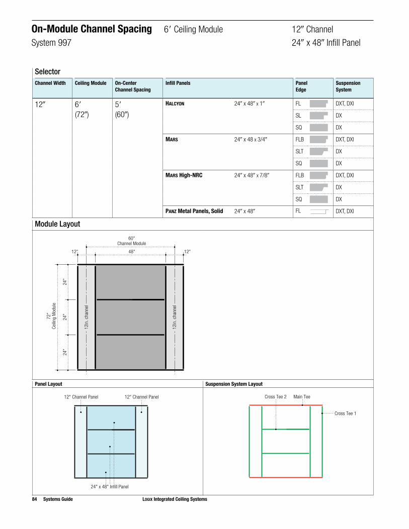
84 Systems Guide LOGIX Integrated Ceiling Systems
Panel Layout Suspension System Layout
24" x 48" Infill Panel
12" Channel Panel 12" Channel Panel
Cross Tee 1
Main TeeCross Tee 2
Module Layout
24"
24"
24"
48"12" 12"
60"Channel Module
72"
Ceilin
g M
odul
e
12in
. cha
nnel
12in
. cha
nnel
SelectorChannel Width Ceiling Module On-Center
Channel SpacingInfill Panels Panel
EdgeSuspension System
12! 6" (72!)
5"(60!)
HALCYON 24! x 48! x 1! FL DXT, DXI
SL DX
SQ DX
MARS 24! x 48 x 3/4! FLB DXT, DXI
SLT DX
SQ DX
MARS High-NRC 24! x 48! x 7/8! FLB DXT, DXI
SLT DX
SQ DX
PANZ Metal Panels, Solid 24! x 48! FL DXT, DXI
On-Module Channel Spacing 6" Ceiling Module 12! ChannelSystem 997 24! x 48! Infill Panel

Suspension System EstimatorLength Sq. Ft. Main Tee
Usage Per Sq. Ft.Cross Tee 1Usage Per Sq. Ft.
Cross Tee 2Usage Per Sq. Ft.
System Module 60! 30 0.17 0.40 0.27
Note: Multiply the ceiling area (SF) by the Usage Factor (UF). This calculation will determine lineal footage of suspension system components required. Please refer to the front of this catalogue or IC592 for stabilizer bar usage.
FL/FLB SL/SLT SQ
Edge Item No. Edge Item No. Edge Item No.
Infill Panels HALCYON 24! x 48! x 1! FL ¨ 98245 SL ¨ 98243 SQ ¨ 98241
MARS 24! x 48! x 3/4! FLB ¨ 88985 SLT ¨ 88785 SQ ¨ 88185
MARS High-NRC 24! x 48! x 7/8! FLB ¨ 89500 SLT ¨ 89600 SQ ¨ 86300
PANZ Metal Panels, Solid 24! x 48! FL ¨ 212164
Channel Panels HALCYON 12! x 72! x 1! FL ¨ 97463 SL ¨ 97435 SQ ¨ 97406
MARS 12! x 72! x 3/4! FLB ¨ 86570 SLT ¨ 86546 SQ ¨ 86518
MARS High-NRC 12! x 72! x 7/8! FLB ¨ 86478 SLT ¨ 86446 SQ ¨ 86409
PANZ Metal Panels, Solid 12! x 72! FL ¨ 202654
Qty Item No. Qty Item No. Qty Item No.
Suspension Systems
CENTRICITEE DXT Main Tee ¨ DXT24
Cross Tee 1 2 ¨ DXT624
Cross Tee 2 2 ¨ DXT424
IDENTITEE DXI Main Tee ¨ DXI24
Cross Tee 1 2 ¨ DXI624
Cross Tee 2 2 ¨ DXI424
DONN DX Main Tee ¨ DX/DXL24 ¨ DX/DXL24
Cross Tee 1 2 ¨ DX624 2 ¨ DX624
Cross Tee 2 2 ¨ DX422 2 ¨ DX422
Order Information 6" Ceiling Module 12! ChannelSystem 997 24! x 48! Infill Panel
Step 3. Select Corresponding Grid for Selected Panels
LOGIX Integrated Ceiling Systems Systems Guide 85
Step 1. Select Panels Step 2. Select Edge for Panels

86 Systems Guide LOGIX Integrated Ceiling Systems
Panel Layout Suspension System Layout
24" x 24" Infill Panel
12" Channel Panel 12" Channel Panel
Cross Tee 1
Main TeeCross Tee 3
Cross Tee 2
Module Layout
24"
24"
24"
24"12" 12"24"
60"Channel Module
72"
Ceilin
g M
odul
e
12in
. cha
nnel
12in
. cha
nnel
SelectorChannel Width Ceiling Module On-Center
Channel SpacingInfill Panels Panel
EdgeSuspension System
12! 6"(72!)
5"(60!)
HALCYON 24! x 24! x 1! FL DXT, DXI
SL DX
SQ DX, DXT
MARS 24! x 24! x 3/4! FLB DXT, DXI
SLT DX
SQ DX, DXT
MARS High-NRC 24! x 24! x 7/8! FLB DXT, DXI
SLT DX
SQ DX, DXT
PANZ Metal Panels, Solid 24! x 24! FL DXT, DXI
On-Module Channel Spacing 6" Ceiling Module 12! ChannelSystem 665 24! x 24! Infill Panel

Suspension System EstimatorLength Sq. Ft. Main Tee
Usage Per Sq. Ft.Cross Tee 1Usage Per Sq. Ft.
Cross Tee 2Usage Per Sq. Ft.
Cross Tee 3Usage Per Sq. Ft.
System Module 60! 30 0.17 0.40 0.20 0.27
Note: Multiply the ceiling area (SF) by the Usage Factor (UF). This calculation will determine lineal footage of suspension system components required. Please refer to the front of this catalogue or IC592 for stabilizer bar usage.
FL/FLB SL/SLT SQ
Edge Item No. Edge Item No. Edge Item No.
Infill Panels HALCYON 24! x 24! x 1! FL ¨ 98225 SL ¨ 98223 SQ ¨ 98221
MARS 24! x 24! x 3/4! FLB ¨ 86985 SLT ¨ 86785 SQ ¨ 86185
MARS High-NRC 24! x 24! x 7/8! FLB ¨ 87100 SLT ¨ 87200 SQ ¨ 86100
PANZ Metal Panels, Solid 24! x 24! FL ¨ 275616
Channel Panels HALCYON 12! x 72! x 1! FL ¨ 97463 SL ¨ 97435 SQ ¨ 97406
MARS 12! x 72! x 3/4! FLB ¨ 86570 SLT ¨ 86546 SQ ¨ 86518
MARS High-NRC 12! x 72! x 7/8! FLB ¨ 86478 SLT ¨ 86446 SQ ¨ 86409
PANZ Metal Panels, Solid 12! x 72! FL ¨ 202654
Qty Item No. Qty Item No. Qty Item No.
Suspension Systems
CENTRICITEE DXT Main Tee ¨ DXT24 ¨ DXT24
Cross Tee 1 2 ¨ DXT624 2 ¨ DXT624
Cross Tee 2 1 ¨ DXT624 1 ¨ DXT624
Cross Tee 3 4 ¨ DXT222 4 ¨ DXT222
IDENTITEE DXI Main Tee ¨ DXI24
Cross Tee 1 2 ¨ DXI624
Cross Tee 2 1 ¨ DXI624
Cross Tee 3 4 ¨ DXI222
DONN DX Main Tee ¨ DX/DXL24 ¨ DX/DXL24
Cross Tee 1 2 ¨ DX624 2 ¨ DX624
Cross Tee 2 1 ¨ DX624 1 ¨ DX624
Cross Tee 3 4 ¨ DX216 4 ¨ DX216
Order Information 6" Ceiling Module 12! ChannelSystem 665 24! x 24! Infill Panel
Step 3. Select Corresponding Grid for Selected Panels
LOGIX Integrated Ceiling Systems Systems Guide 87
Step 1. Select Panels Step 2. Select Edge for Panels

88 Systems Guide LOGIX Integrated Ceiling Systems
Panel Layout Suspension System Layout
12" Channel Panel 12" Channel Panel
72" x 24" Infill Panel
Cross Tee 1
Main Tee
Cross Tee 2
Module Layout
24"12" 12"24"
60"Channel Module
72"
Ceilin
g M
odul
e
12in
. cha
nnel
12in
. cha
nnel
SelectorChannel Width Ceiling Module On-Center
Channel SpacingInfill Panels Panel
EdgeSuspension System
12! 6"(72!)
5"(60!)
HALCYON 24! x 72! x 1! FL DXT, DXI
SL DX
SQ DX
MARS 24! x 72! x 3/4! FLB DXT, DXI
SLT DX
SQ DX
MARS High-NRC 24! x 72! x 7/8! FLB DXT, DXI
SLT DX
SQ DX
PANZ Metal Panels, Solid 24! x 72! FL DXT, DXI
On-Module Channel Spacing 6" Ceiling Module 12! ChannelSystem 785 24! x 72! Infill Panel

Suspension System EstimatorLength Sq. Ft. Main Tee
Usage Per Sq. Ft.Cross Tee 1Usage Per Sq. Ft.
Cross Tee 2Usage Per Sq. Ft.
System Module 60! 30 0.17 0.40 0.20
Note: Multiply the ceiling area (SF) by the Usage Factor (UF). This calculation will determine lineal footage of suspension system components required. Please refer to the front of this catalogue or IC592 for stabilizer bar usage.
FL/FLB SL/SLT SQ
Edge Item No. Edge Item No. Edge Item No.
Infill Panels HALCYON 24! x 72! x 1! FL ¨ 98348 SL ¨ 99268 SQ ¨ 99234
MARS 24! x 72! x 3/4! FLB ¨ 88996 SLT ¨ 86166 SQ ¨ 86223
MARS High-NRC 24! x 72! x 7/8! FLB ¨ 89670 SLT ¨ 89660 SQ ¨ 86360
PANZ Metal Panels, Solid 24! x 72! FL ¨ 212192
Channel Panels HALCYON 12! x 72! x 1! FL ¨ 97463 SL ¨ 97435 SQ ¨ 97406
MARS 12! x 72! x 3/4! FLB ¨ 86570 SLT ¨ 86546 SQ ¨ 86518
MARS High-NRC 12! x 72! x 7/8! FLB ¨ 86478 SLT ¨ 86446 SQ ¨ 86409
PANZ Metal Panels, Solid 12! x 72! FL ¨ 202654
Qty Item No. Qty Item No. Qty Item No.
Suspension Systems
CENTRICITEE DXT Main Tee ¨ DXT24
Cross Tee 1 2 ¨ DXT624
Cross Tee 2 1 ¨ DXT624
IDENTITEE DXI Main Tee ¨ DXI24
Cross Tee 1 2 ¨ DXI624
Cross Tee 2 1 ¨ DXI624
DONN DX Main Tee ¨ DX/DXL24 ¨ DX/DXL24
Cross Tee 1 2 ¨ DX624 2 ¨ DX624
Cross Tee 2 1 ¨ DX624 1 ¨ DX624
Order Information 6" Ceiling Module 12! ChannelSystem 785 24! x 72! Infill Panel
Step 3. Select Corresponding Grid for Selected Panels
LOGIX Integrated Ceiling Systems Systems Guide 89
Step 1. Select Panels Step 2. Select Edge for Panels

90 Systems Guide LOGIX Integrated Ceiling Systems
SelectorChannel Width Ceiling Module On-Center
Channel SpacingInfill Panels Panel
EdgeSuspension System
4! 4"(48!)
4"- 4!(52!)
HALCYON 24! x 48! x 1! FL DXT, DXI
SL DX
SQ DX
MARS 24! x 48! x 3/4! FLB DXT, DXI
SLT DX
SQ DX
MARS High-NRC 24! x 48! x 7/8! FLB DXT, DXI
SLT DX
SQ DX
PANZ Metal Panels, Solid 24! x 48! FL DXT, DXI
Panel Layout Suspension System Layout
24" x 48" Infill Panel
4" Channel Panel 4" Channel Panel
Cross Tee 1
Main Tee
Cross Tee 2
Module Layout
24"4" 4"24"
52"Channel Module
48"
Ceilin
g M
odul
e
4in.
cha
nnel
4in.
cha
nnel
Off-Module Channel Spacing 4" Ceiling Module 4! ChannelSystem 367 24! x 48! Infill Panel

Suspension System EstimatorLength Sq. Ft. Main Tee
Usage Per Sq. Ft.Cross Tee 1Usage Per Sq. Ft.
Cross Tee 2Usage Per Sq. Ft.
System Module 52! 17.333 0.25 0.46 0.23
Note: Multiply the ceiling area (SF) by the Usage Factor (UF). This calculation will determine lineal footage of suspension system components required. Please refer to the front of this catalogue or IC592 for stabilizer bar usage.
Step 3. Select Corresponding Grid for Selected Panels
FL/FLB SL/SLT SQ
Edge Item No. Edge Item No. Edge Item No.
Infill Panels HALCYON 24! x 48! x 1! FL ¨ 98245 SL ¨ 98243 SQ ¨ 98241
MARS 24! x 48! x 3/4! FLB ¨ 88985 SLT ¨ 88785 SQ ¨ 88185
MARS High-NRC 24! x 48! x 7/8! FLB ¨ 89500 SLT ¨ 89600 SQ ¨ 86300
PANZ Metal Panels, Solid 24! x 48! FL ¨ 212164
Channel Panels HALCYON 4! x 48! x 1! FL ¨ 97460 SL ¨ 97430 SQ ¨ 97402
MARS 4! x 48! x 3/4! FLB ¨ 86568 SLT ¨ 86540 SQ ¨ 86514
MARS High-NRC 4! x 48! x 7/8! FLB ¨ 86475 SLT ¨ 86440 SQ ¨ 86402
PANZ Metal Panels, Solid 4! x 48! FL ¨ 202636
Qty Item No. Qty Item No. Qty Item No.
Suspension Systems
CENTRICITEE DXT Main Tee ¨ DXT24SP103
Cross Tee 1 2 ¨ DXT424
Cross Tee 2 1 ¨ DXT424
IDENTITEE DXI Main Tee ¨ DXI24SP103
Cross Tee 1 2 ¨ DXI424
Cross Tee 2 1 ¨ DXI424
DONN DX Main Tee ¨ DX24SP103 ¨ DX24SP103
Cross Tee 1 2 ¨ DX422 2 ¨ DX422
Cross Tee 2 1 ¨ DX422 1 ¨ DX422
Order Information 4" Ceiling Module 4! ChannelSystem 367 24! x 48! Infill Panel
LOGIX Integrated Ceiling Systems Systems Guide 91
Step 1. Select Panels Step 2. Select Edge for Panels

92 Systems Guide LOGIX Integrated Ceiling Systems
Panel Layout Suspension System Layout
24" x 48" Infill Panel
6" Channel Panel 6" Channel Panel
Cross Tee 1
Main Tee
Cross Tee 2
Module Layout
24"6" 6"24"
54"Channel Module
48"
Ceilin
g M
odul
e
6in.
cha
nnel
6in.
cha
nnel
SelectorChannel Width Ceiling Module On-Center
Channel SpacingInfill Panels Panel
EdgeSuspension System
6! 4"(48!)
4"- 6!(54!)
HALCYON 24! x 48! x 1! FL DXT, DXI
SL DX
SQ DX
MARS 24! x 48 x 3/4! FLB DXT, DXI
SLT DX
SQ DX
MARS High-NRC 24! x 48! x 7/8! FLB DXT, DXI
SLT DX
SQ DX
PANZ Metal Panels, Solid 24! x 48! FL DXT, DXI
Off-Module Channel Spacing 4" Ceiling Module 6! ChannelSystem 598 24! x 48! Infill Panel

Suspension System EstimatorLength Sq. Ft. Main Tee
Usage Per Sq. Ft.Cross Tee 1Usage Per Sq. Ft.
Cross Tee 2Usage Per Sq. Ft.
System Module 54! 18 0.25 .44 .22
Note: Multiply the ceiling area (SF) by the Usage Factor (UF). This calculation will determine lineal footage of suspension system components required. Please refer to the front of this catalogue or IC592 for stabilizer bar usage.
FL/FLB SL/SLT SQ
Edge Item No. Edge Item No. Edge Item No.
Infill Panels HALCYON 24! x 48! x 1! FL ¨ 98245 SL ¨ 98243 SQ ¨ 98241
MARS 24! x 48! x 3/4! FLB ¨ 88985 SLT ¨ 88785 SQ ¨ 88185
MARS High-NRC 24! x 48! x 7/8! FLB ¨ 89500 SLT ¨ 89600 SQ ¨ 86300
PANZ Metal Panels, Solid 24! x 48! FL ¨ 212164
Channel Panels HALCYON 6! x 48! x 1! FL ¨ 98198 SL ¨ 99271 SQ ¨ 97227
MARS 6! x 48! x 3/4! FLB ¨ 88887 SLT ¨ 86542 SQ ¨ 86325
MARS High-NRC 6! x 48! x 7/8! FLB ¨ 86331 SLT ¨ 86442 SQ ¨ 86404
PANZ Metal Panels, Solid 6! x 48! FL ¨ 256820 SL ¨ 256819 SQ ¨ 256768
Panz Metal Panels, Perf C116 6! x 48! FL ¨ 256062 SL ¨ 257248 SQ ¨ 256397
Panz Metal Panels, Perf C116D 6! x 48! FL ¨ 257585 SL ¨ 257584 SQ ¨ 257406
Qty Item No. Qty Item No. Qty Item No.
Suspension Systems
CENTRICITEE DXT Main Tee ¨ DXT24
Cross Tee 1 2 ¨ DXT424
Cross Tee 2 1 ¨ DXT424
IDENTITEE DXI Main Tee ¨ DXI24
Cross Tee 1 2 ¨ DXI424
Cross Tee 2 1 ¨ DXI424
DONN DX Main Tee ¨ DX/DXL24 ¨ DX/DXL24
Cross Tee 1 2 ¨ DX422 2 ¨ DX422
Cross Tee 2 1 ¨ DX422 1 ¨ DX422
Order Information 4" Ceiling Module 6! ChannelSystem 598 24! x 48! Infill Panel
Step 3. Select Corresponding Grid for Selected Panels
LOGIX Integrated Ceiling Systems Systems Guide 93
Step 1. Select Panels Step 2. Select Edge for Panels

94 Systems Guide LOGIX Integrated Ceiling Systems
SelectorChannel Width Ceiling Module On-Center
Channel SpacingInfill Panels Panel
EdgeSuspension System
4! 4"(48!)
4"- 4!(52!)
HALCYON 24! x 24! x 1! FL DXT, DXI
SL DX
SQ DX, DXT
MARS 24! x 24! x 3/4! FLB DXT, DXI
SLT DX
SQ DX, DXT
MARS High-NRC 24! x 24! x 7/8! FLB DXT, DXI
SLT DX
SQ DX, DXT
PANZ Metal Panels, Solid 24! x 24! FL DXT, DXI
Panel Layout Suspension System Layout
24" x 24" Infill Panel
4" Channel Panel 4" Channel Panel
Cross Tee 1
Main TeeCross Tee 3
Cross Tee 2
Module Layout
24"
24"
24"4" 4"24"
52"Channel Module
48"
Ceilin
g M
odul
e
4in.
cha
nnel
4in.
cha
nnel
Off-Module Channel Spacing 4" Ceiling Module 4! ChannelSystem 977 24! x 24! Infill Panel

Suspension System EstimatorLength Sq. Ft. Main Tee
Usage Per Sq. Ft.Cross Tee 1Usage Per Sq. Ft.
Cross Tee 2Usage Per Sq. Ft.
Cross Tee 3Usage Per Sq. Ft.
System Module 54! 18 0.25 0.44 0.22 0.22
Note: Multiply the ceiling area (SF) by the Usage Factor (UF). This calculation will determine lineal footage of suspension system components required. Please refer to the front of this catalogue or IC592 for stabilizer bar usage.
Step 3. Select Corresponding Grid for Selected Panels
FL/FLB SL/SLT SQ
Edge Item No. Edge Item No. Edge Item No.
Infill Panels HALCYON 24! x 24! x 1! FL ¨ 98225 SL ¨ 98223 SQ ¨ 98221
MARS 24! x 24! x 3/4! FLB ¨ 86985 SLT ¨ 86785 SQ ¨ 86185
MARS High-NRC 24! x 24! x 7/8! FLB ¨ 87100 SLT ¨ 87200 SQ ¨ 86100
PANZ Metal Panels, Solid 24! x 24! FL ¨ 275616
Channel Panels HALCYON 4! x 48! x 1! FL ¨ 97460 SL ¨ 97430 SQ ¨ 97402
MARS 4! x 48! x 3/4! FLB ¨ 86568 SLT ¨ 86540 SQ ¨ 86514
MARS High-NRC 4! x 48! x 7/8! FLB ¨ 86475 SLT ¨ 86440 SQ ¨ 86402
Qty Item No. Qty Item No. Qty Item No.
Suspension Systems
CENTRICITEE DXT Main Tee ¨ DXT24SP103 1 ¨ DXT24SP103
Cross Tee 1 2 ¨ DXT424 2 ¨ DXT424
Cross Tee 2 1 ¨ DXT424 1 ¨ DXT424
Cross Tee 3 2 ¨ DXT222 2 ¨ DXT222
IDENTITEE DXI Main Tee ¨ DXI24SP103
Cross Tee 1 2 ¨ DXI424
Cross Tee 2 1 ¨ DXI424
Cross Tee 3 2 ¨ DXI222
DONN DX Main Tee ¨ DX24SP103 ¨ DX24SP103
Cross Tee 1 2 ¨ DX422 2 ¨ DX422
Cross Tee 2 1 ¨ DX422 1 ¨ DX422
Cross Tee 3 2 ¨ DX216 2 ¨ DX216
Order Information 4" Ceiling Module 4! ChannelSystem 977 24! x 24! Infill Panel
LOGIX Integrated Ceiling Systems Systems Guide 95
Step 1. Select Panels Step 2. Select Edge for Panels

96 Systems Guide LOGIX Integrated Ceiling Systems
Panel Layout Suspension System Layout
24" x 24" Infill Panel
6" Channel Panel 6" Channel Panel
Cross Tee 1
Main TeeCross Tee 3
Cross Tee 2
Module Layout
24"
24"
24"6" 6"24"
54"Channel Module
48"
Ceilin
g M
odul
e
6in.
cha
nnel
6in.
cha
nnel
SelectorChannel Width Ceiling Module On-Center
Channel SpacingInfill Panels Panel
EdgeSuspension System
6! 4"(48!)
4"- 6!(54!)
HALCYON 24! x 24! x 1! FL DXT, DXI
SL DX
SQ DX, DXT
MARS 24! x 24! x 3/4! FLB DXT, DXI
SLT DX
SQ DX, DXT
MARS High-NRC 24! x 24! x 7/8! FLB DXT, DXI
SLT DX
SQ DX, DXT
PANZ Metal Panels, Solid 24! x 24! FL DXT, DXI
Off-Module Channel Spacing 4" Ceiling Module 6! ChannelSystem 862 24! x 24! Infill Panel

Suspension System EstimatorLength Sq. Ft. Main Tee
Usage Per Sq. Ft.Cross Tee 1Usage Per Sq. Ft.
Cross Tee 2Usage Per Sq. Ft.
Cross Tee 3Usage Per Sq. Ft.
System Module 54! 18 0.25 0.44 0.22 0.22
Note: Multiply the ceiling area (SF) by the Usage Factor (UF). This calculation will determine lineal footage of suspension system components required. Please refer to the front of this catalogue or IC592 for stabilizer bar usage.
FL/FLB SL/SLT SQ
Edge Item No. Edge Item No. Edge Item No.
Infill Panels HALCYON 24! x 24! x 1! FL ¨ 98225 SL ¨ 98223 SQ ¨ 98221
MARS 24! x 24! x 3/4! FLB ¨ 86985 SLT ¨ 86785 SQ ¨ 86185
MARS High-NRC 24! x 24! x 7/8! FLB ¨ 87100 SLT ¨ 87200 SQ ¨ 86100
PANZ Metal Panels, Solid 24! x 24! FL ¨ 275616
Channel Panels HALCYON 6! x 48! x 1! FL ¨ 97572 SL ¨ 99271 SQ ¨ 97227
MARS 6! x 48! x 3/4! FLB ¨ 88887 SLT ¨ 86542 SQ ¨ 86325
MARS High-NRC 6! x 48! x 7/8! FLB ¨ 86331 SLT ¨ 86442 SQ ¨ 86404
PANZ Metal Panels, Solid 6! x 48! FL ¨ 256820 SL ¨ 256819 SQ ¨ 256768
Panz Metal Panels, Perf C116 6! x 48! FL ¨ 256062 SL ¨ 257248 SQ ¨ 256397
Panz Metal Panels, Perf C116D 6! x 48! FL ¨ 257585 SL ¨ 257584 SQ ¨ 257406
Qty Item No. Qty Item No. Qty Item No.
Suspension Systems
CENTRICITEE DXT Main Tee ¨ DXT24 ¨ DXT24
Cross Tee 1 2 ¨ DXT424 2 ¨ DXT424
Cross Tee 2 1 ¨ DXT424 1 ¨ DXT424
Cross Tee 3 2 ¨ DXT222 2 ¨ DXT222
IDENTITEE DXI Main Tee ¨ DXI24
Cross Tee 1 2 ¨ DXI424
Cross Tee 2 1 ¨ DXI424
Cross Tee 3 2 ¨ DXI222
DONN DX Main Tee ¨ DX/DXL24 ¨ DX/DXL24
Cross Tee 1 2 ¨ DX422 2 ¨ DX422
Cross Tee 2 1 ¨ DX422 1 ¨ DX422
Cross Tee 3 2 ¨ DX216 2 ¨ DX216
Order Information 4" Ceiling Module 6! ChannelSystem 862 24! x 24! Infill Panel
Step 3. Select Corresponding Grid for Selected Panels
LOGIX Integrated Ceiling Systems Systems Guide 97
Step 1. Select Panels Step 2. Select Edge for Panels

98 Systems Guide LOGIX Integrated Ceiling Systems
SelectorChannel Width Ceiling Module On-Center
Channel SpacingInfill Panels Panel
EdgeSuspension System
4! 4"(48!)
4"- 4!(52!)
HALCYON 48! x 48! x 1! FL DXT, DXI
SL DX
SQ DX
Panel Layout Suspension System Layout
48" x 48" Infill Panel
4" Channel Panel 4" Channel Panel
Cross Tee 1
Main Tee
Module Layout
48"4" 4"
52"Channel Module
48"
Ceilin
g M
odul
e
4in.
cha
nnel
4in.
cha
nnel
`
Off-Module Channel Spacing 4" Ceiling Module 4! ChannelSystem 527 48! x 48! Infill Panel

Suspension System EstimatorLength Sq. Ft. Main Tee
Usage Per Sq. Ft.Cross Tee 1Usage Per Sq. Ft.
System Module 52! 17.333 0.25 0.46
Note: Multiply the ceiling area (SF) by the Usage Factor (UF). This calculation will determine lineal footage of suspension system components required. Please refer to the front of this catalogue or IC592 for stabilizer bar usage.
Step 3. Select Corresponding Grid for Selected Panels
FL/FLB SL/SLT SQ
Edge Item No. Edge Item No. Edge Item No.
Infill Panels HALCYON 48! x 48! x 1! FL ¨ 98445 SL ¨ 98443 SQ ¨ 98441
Channel Panels HALCYON 4! x 48! x 1! FL ¨ 97460 SL ¨ 97430 SQ ¨ 97402
HALCYON 6! x 48! x 1! FL ¨ 98198 SL ¨ 99271 SQ ¨ 97227
Qty Item No. Qty Item No. Qty Item No.
Suspension Systems
CENTRICITEE DXT Main Tee ¨ DXT24SP103
Cross Tee 1 2 ¨ DXT424
IDENTITEE DXI Main Tee ¨ DXI24SP103
Cross Tee 1 2 ¨ DXI424
DONN DX Main Tee ¨ DX24SP103 ¨ DX24SP103
Cross Tee 1 2 ¨ DX422 2 ¨ DX422
Order Information 4" Ceiling Module 4! ChannelSystem 527 48! x 48! Infill Panel
LOGIX Integrated Ceiling Systems Systems Guide 99
Step 1. Select Panels Step 2. Select Edge for Panels

100 Systems Guide LOGIX Integrated Ceiling Systems
Panel Layout Suspension System Layout
48" x 48" Infill Panel
6" Channel Panel 6" Channel Panel
Cross Tee 1
Main Tee
Module Layout
48"6" 6"
54"Channel Module
48"
Ceilin
g M
odul
e
6in.
cha
nnel
6in.
cha
nnel
SelectorChannel Width Ceiling Module On-Center
Channel SpacingInfill Panels Panel
EdgeSuspension System
6! 4"(48!)
4"- 6!(54!)
HALCYON 48! x 48! x 1! FL DXT, DXI
SL DX
SQ DX
Off-Module Channel Spacing 4" Ceiling Module 6! ChannelSystem 244 48! x 48! Infill Panel
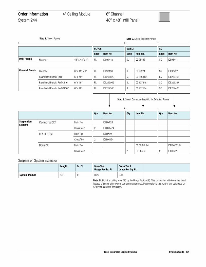
Suspension System EstimatorLength Sq. Ft. Main Tee
Usage Per Sq. Ft.Cross Tee 1Usage Per Sq. Ft.
System Module 54! 18 0.25 0.44
Note: Multiply the ceiling area (SF) by the Usage Factor (UF). This calculation will determine lineal footage of suspension system components required. Please refer to the front of this catalogue or IC592 for stabilizer bar usage.
Step 3. Select Corresponding Grid for Selected Panels
FL/FLB SL/SLT SQ
Edge Item No. Edge Item No. Edge Item No.
Infill Panels HALCYON 48! x 48! x 1! FL ¨ 98445 SL ¨ 98443 SQ ¨ 98441
Channel Panels HALCYON 6! x 48! x 1! FL ¨ 98198 SL ¨ 99271 SQ ¨ 97227
PANZ Metal Panels, Solid 6! x 48! FL ¨ 256820 SL ¨ 256819 SQ ¨ 256768
Panz Metal Panels, Perf C116 6! x 48! FL ¨ 256062 SL ¨ 257248 SQ ¨ 256397
Panz Metal Panels, Perf C116D 6! x 48! FL ¨ 257585 SL ¨ 257584 SQ ¨ 257406
Qty Item No. Qty Item No. Qty Item No.
Suspension Systems
CENTRICITEE DXT Main Tee ¨ DXT24
Cross Tee 1 2 ¨ DXT424
IDENTITEE DXI Main Tee ¨ DXI24
Cross Tee 1 2 ¨ DXI424
DONN DX Main Tee ¨ DX/DXL24 ¨ DX/DXL24
Cross Tee 1 2 ¨ DX422 2 ¨ DX422
Order Information 4" Ceiling Module 6! ChannelSystem 244 48! x 48! Infill Panel
LOGIX Integrated Ceiling Systems Systems Guide 101
Step 1. Select Panels Step 2. Select Edge for Panels

102 Systems Guide LOGIX Integrated Ceiling Systems
Panel Layout Suspension System Layout
72" x 24" Field Panel
4" Channel Panel 4" Channel Panel
Cross Tee 1
Main TeeCross Tee 2
Module Layout
24"
24"
72"4" 4"
76"Channel Module
48"
Ceilin
g M
odul
e
4in.
cha
nnel
4in.
cha
nnel
SelectorChannel Width Ceiling Module On-Center
Channel SpacingInfill Panels Panel
EdgeSuspension System
4! 4"(48!)
6"- 4!(76!)
HALCYON 72! x 24! x 1! FL DXT, DXI
MARS 72! x 24! x 3/4! FLB DXT, DXI
MARS High-NRC 72! x 24! x 7/8! FLB DXT, DXI
PANZ Metal Panels, Solid 72! x 24! FL DXT, DXI
Off-Module Channel Spacing 4" Ceiling Module 4! ChannelSystem 529 72! x 24! Infill Panel

Suspension System EstimatorLength Sq. Ft. Main Tee
Usage Per Sq. Ft.Cross Tee 1Usage Per Sq. Ft.
Cross Tee 2Usage Per Sq. Ft.
System Module 78! 26 0.25 0.31 0.23
Note: Multiply the ceiling area (SF) by the Usage Factor (UF). This calculation will determine lineal footage of suspension system components required. Please refer to the front of this catalogue or IC592 for stabilizer bar usage.
FL/FLB SL/SLT SQ
Edge Item No. Edge Item No. Edge Item No.
Infill Panels HALCYON 72! x 24! x 1! FL ¨ 98348
MARS 72! x 24! x 3/4! FLB ¨ 88996
MARS High-NRC 72! x 24! x 7/8! FLB ¨ 89670
PANZ Metal Panels, Solid 72! x 24! FL ¨ 212192
Channel Panels HALCYON 4! x 48! x 1! FL ¨ 97460 SL ¨ 97430 SQ ¨ 97402
MARS 4! x 48! x 3/4! FLB ¨ 86568
MARS High-NRC 4! x 48! x 7/8! FLB ¨ 86475
PANZ Metal Panels, Solid 4! x 48! FL ¨ 202636
Qty Item No. Qty Item No. Qty Item No.
Suspension Systems
CENTRICITEE DXT Main Tee ¨ DXTSP110
Cross Tee 1 2 ¨ DXT424
Cross Tee 2 1 ¨ DXT624
IDENTITEE DXI Main Tee ¨ DXISP110
Cross Tee 1 2 ¨ DXI424
Cross Tee 2 1 ¨ DXI624
Order Information 4" Ceiling Module 4! ChannelSystem 529 72! x 24! Infill Panel
Step 3. Select Corresponding Grid for Selected Panels
LOGIX Integrated Ceiling Systems Systems Guide 103
Step 1. Select Panels Step 2. Select Edge for Panels

104 Systems Guide LOGIX Integrated Ceiling Systems
Panel Layout Suspension System Layout
72" x 24" Infill Panel
6" Channel Panel 6" Channel Panel
Cross Tee 1
Main TeeCross Tee 2
Module Layout
24"
24"
72"6" 6"
78"Channel Module
48"
Ceilin
g M
odul
e
6in.
cha
nnel
6in.
cha
nnel
SelectorChannel Width Ceiling Module On-Center
Channel SpacingInfill Panels Panel
EdgeSuspension System
6! 4"(48!)
6"- 6!(78!)
HALCYON 72! x 24! x 1! FL DXT, DXI
SL DX
SQ DX
MARS 72! x 24! x 3/4! FLB DXT, DXI
SLT DX
SQ DX
MARS High-NRC 72! x 24! x 7/8! FLB DXT, DXI
SLT DX
SQ DX
PANZ Metal Panels, Solid 72! x 24! FL DXT, DXI
Off-Module Channel Spacing 4" Ceiling Module 6! ChannelSystem 755 72! x 24! Infill Panel

Suspension System EstimatorLength Sq. Ft. Main Tee
Usage Per Sq. Ft.Cross Tee 1Usage Per Sq. Ft.
Cross Tee 2Usage Per Sq. Ft.
System Module 78! 26 0.25 0.31 0.23
Note: Multiply the ceiling area (SF) by the Usage Factor (UF). This calculation will determine lineal footage of suspension system components required. Please refer to the front of this catalogue or IC592 for stabilizer bar usage.
FL/FLB SL/SLT SQ
Edge Item No. Edge Item No. Edge Item No.
Infill Panels HALCYON 72! x 24! x 1! FL ¨ 98348 SL ¨ 99268 SQ ¨ 99234
MARS 72! x 24! x 3/4! FLB ¨ 88996 SLT ¨ 86166 SQ ¨ 86223
MARS High-NRC 72! x 24! x 7/8! FLB ¨ 89670 SLT ¨ 89660 SQ ¨ 86360
PANZ Metal Panels, Solid 72! x 24! FL ¨ 212192
Channel Panels HALCYON 6! x 48! x 1! FL ¨ 98198 SL ¨ 99271 SQ ¨ 97227
MARS 6! x 48! x 3/4! FLB ¨ 88887 SLT ¨ 86542 SQ ¨ 86325
MARS High-NRC 6! x 48! x 7/8! FLB ¨ 86331 SLT ¨ 86442 SQ ¨ 86404
PANZ Metal Panels, Solid 6! x 48! FL ¨ 256820 SL ¨ 256819 SQ ¨ 256768
Panz Metal Panels, Perf C116 6! x 48! FL ¨ 256062 SL ¨ 257248 SQ ¨ 256397
Panz Metal Panels, Perf C116D 6! x 48! FL ¨ 257585 SL ¨ 257584 SQ ¨ 257406
Qty Item No. Qty Item No. Qty Item No.
Suspension Systems
CENTRICITEE DXT Main Tee ¨ DXT24
Cross Tee 1 2 ¨ DXT424
Cross Tee 2 1 ¨ DXT624
IDENTITEE DXI Main Tee ¨ DXI24
Cross Tee 1 2 ¨ DXI424
Cross Tee 2 1 ¨ DXI624
DONN DX Main Tee ¨ DX/DXL24 ¨ DX/DXL24
Cross Tee 1 2 ¨ DX422 2 ¨ DX422
Cross Tee 2 1 ¨ DX624 1 ¨ DX624
Order Information 4" Ceiling Module 6! ChannelSystem 755 72! x 24! Infill Panel
Step 3. Select Corresponding Grid for Selected Panels
LOGIX Integrated Ceiling Systems Systems Guide 105
Step 1. Select Panels Step 2. Select Edge for Panels

106 Systems Guide LOGIX Integrated Ceiling Systems
Panel Layout Suspension System Layout
24" x 24" Infill Panel
6" Channel Panel 6" Channel Panel
Cross Tee 1
Main Tee
Cross Tee 3
Cross Tee 2
Module Layout
24"
24"
24" 24" 24"6" 6"
78"Channel Module
48"
Ceilin
g M
odul
e
6in.
cha
nnel
6in.
cha
nnel
SelectorChannel Width Ceiling Module On-Center
Channel SpacingInfill Panels Panel
EdgeSuspension System
6! 4"(48!)
6"- 6!(78!)
HALCYON 24! x 24! x 1! FL DXT, DXI
SL DX
SQ DX, DXT
MARS 24! x 24! x 3/4! FLB DXT, DXI
SLT DX
SQ DX, DXT
MARS High-NRC 24! x 24! x 7/8! FLB DXT, DXI
SLT DX
SQ DX, DXT
PANZ Metal Panels, Solid 24! x 24! FL DXT, DXI
Off-Module Channel Spacing 4" Ceiling Module 6! ChannelSystem 574 24! x 24! Infill Panel

Suspension System EstimatorLength Sq. Ft. Main Tee
Usage Per Sq. Ft.Cross Tee 1Usage Per Sq. Ft.
Cross Tee 2Usage Per Sq. Ft.
Cross Tee 3Usage Per Sq. Ft.
System Module 78! 26 0.25 0.31 0.31 0.23
Note: Multiply the ceiling area (SF) by the Usage Factor (UF). This calculation will determine lineal footage of suspension system components required. Please refer to the front of this catalogue or IC592 for stabilizer bar usage.
Step 3. Select Corresponding Grid for Selected Panels
FL/FLB SL/SLT SQ
Edge Item No. Edge Item No. Edge Item No.
Infill Panels HALCYON 24! x 24! x 1! FL ¨ 98225 SL ¨ 98223 SQ ¨ 98221
MARS 24! x 24! x 3/4! FLB ¨ 86985 SLT ¨ 86785 SQ ¨ 86185
MARS High-NRC 24! x 24! x 7/8! FLB ¨ 87100 SLT ¨ 87200 SQ ¨ 86100
PANZ Metal Panels, Solid 24! x 24! FL ¨ 275616
Channel Panels MARS 4! x 48! x 3/4! FLB ¨ 86568 SLT ¨ 86540 SQ ¨ 86514
MARS High-NRC 4! x 48! x 7/8! FLB ¨ 86475 SLT ¨ 86440 SQ ¨ 86402
PANZ Metal Panels, Solid 4! x 48! FL ¨ 202636
Qty Item No. Qty Item No. Qty Item No.
Suspension Systems
CENTRICITEE DXT Main Tee ¨ DXT24 ¨ DXT24
Cross Tee 1 2 ¨ DXT424 2 ¨ DXT424
Cross Tee 2 2 ¨ DXT424 2 ¨ DXT424
Cross Tee 3 3 ¨ DXT222 3 ¨ DXT222
IDENTITEE DXI Main Tee ¨ DXI24
Cross Tee 1 2 ¨ DXI424
Cross Tee 2 3 ¨ DXI424
Cross Tee 3 3 ¨ DXI222
DONN DX Main Tee ¨ DX/DXL24 ¨ DX/DXL24
Cross Tee 1 2 ¨ DX422 2 ¨ DX422
Cross Tee 2 2 ¨ DX422 2 ¨ DX422
Cross Tee 3 3 ¨ DX216 3 ¨ DX216
Order Information 4" Ceiling Module 6! ChannelSystem 574 24! x 24! Infill Panel
LOGIX Integrated Ceiling Systems Systems Guide 107
Step 1. Select Panels Step 2. Select Edge for Panels

108 Systems Guide LOGIX Integrated Ceiling Systems
Panel Layout Suspension System Layout
42" x 48" Infill Panel
6" Channel Panel 6" Channel Panel
Cross Tee 1
Main Tee
Cross Tee 2
Module Layout
42"6" 6"42"
86"Channel Module
48"
Ceilin
g M
odul
e
6in.
cha
nnel
6in.
cha
nnel
SelectorChannel Width Ceiling Module On-Center
Channel SpacingInfill Panels Panel
EdgeSuspension System
6! 4"(48!)
7"- 6!(80!)
HALCYON 42! x 48! x 1! FL DXT, DXI
SL DX
SQ DX
Off-Module Channel Spacing 4" Ceiling Module 4! ChannelSystem 497 42! x 48! Infill Panel

Suspension System EstimatorLength Sq. Ft. Main Tee
Usage Per Sq. Ft.Cross Tee 1Usage Per Sq. Ft.
Cross Tee 2Usage Per Sq. Ft.
System Module 90! 30 0.25 0.27 0.13
Note: Multiply the ceiling area (SF) by the Usage Factor (UF). This calculation will determine lineal footage of suspension system components required. Please refer to the front of this catalogue or IC592 for stabilizer bar usage.
Step 3. Select Corresponding Grid for Selected Panels
FL/FLB SL/SLT SQ
Edge Item No. Edge Item No. Edge Item No.
Infill Panels HALCYON 42! x 48! x 1! FL ¨ 98343 SL ¨ 97454 SQ ¨ 97424
Channel Panels HALCYON 6! x 48! x 1! FL ¨ 98198 SL ¨ 99271 SQ ¨ 97227
PANZ Metal Panels, Solid 6! x 48! FL ¨ 256820 SL ¨ 256819 SQ ¨ 256768
Panz Metal Panels, Perf C116 6! x 48! FL ¨ 256062 SL ¨ 257248 SQ ¨ 256397
Panz Metal Panels, Perf C116D 6! x 48! FL ¨ 257585 SL ¨ 257584 SQ ¨ 257406
Qty Item No. Qty Item No. Qty Item No.
Suspension Systems
CENTRICITEE DXT Main Tee ¨ DXT24
Cross Tee 1 2 ¨ DXT424
Cross Tee 2 1 ¨ DXT424
IDENTITEE DXI Main Tee ¨ DXI24
Cross Tee 1 2 ¨ DXI424
Cross Tee 2 1 ¨ DXI424
DONN DX Main Tee ¨ DX/DXL24 ¨ DX/DXL24
Cross Tee 1 2 ¨ DX422 2 ¨ DX422
Cross Tee 2 1 ¨ DX422 1 ¨ DX422
Order Information 4" Ceiling Module 4! ChannelSystem 497 42! x 48! Infill Panel
LOGIX Integrated Ceiling Systems Systems Guide 109
Step 1. Select Panels Step 2. Select Edge for Panels

110 Systems Guide LOGIX Integrated Ceiling Systems
Panel Layout Suspension System Layout
96" x 24" Infill Panel
4" Channel Panel 4" Channel Panel
Cross Tee 1
Main TeeCross Tee 2
Module Layout
24"
24"
96"4" 4"
100"Channel Module
48"
Ceilin
g M
odul
e
4in.
cha
nnel
4in.
cha
nnel
SelectorChannel Width Ceiling Module On-Center
Channel SpacingInfill Panels Panel
EdgeSuspension System
4! 4"(48!)
8"- 4!(100!)
HALCYON 96! x 24! x 1! FL DXT, DXI
SL DX
SQ DX
Off-Module Channel Spacing 4" Ceiling Module 4! ChannelSystem 722 96! x 24! Infill Panel
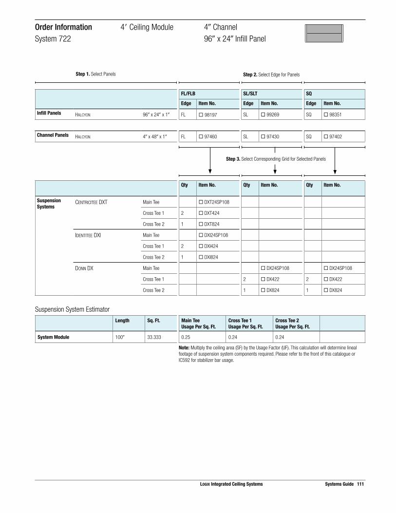
Suspension System EstimatorLength Sq. Ft. Main Tee
Usage Per Sq. Ft.Cross Tee 1Usage Per Sq. Ft.
Cross Tee 2Usage Per Sq. Ft.
System Module 100! 33.333 0.25 0.24 0.24
Note: Multiply the ceiling area (SF) by the Usage Factor (UF). This calculation will determine lineal footage of suspension system components required. Please refer to the front of this catalogue or IC592 for stabilizer bar usage.
Step 3. Select Corresponding Grid for Selected Panels
FL/FLB SL/SLT SQ
Edge Item No. Edge Item No. Edge Item No.
Infill Panels HALCYON 96! x 24! x 1! FL ¨ 98197 SL ¨ 99269 SQ ¨ 98351
Channel Panels HALCYON 4! x 48! x 1! FL ¨ 97460 SL ¨ 97430 SQ ¨ 97402
Qty Item No. Qty Item No. Qty Item No.
Suspension Systems
CENTRICITEE DXT Main Tee ¨ DXT24SP108
Cross Tee 1 2 ¨ DXT424
Cross Tee 2 1 ¨ DXT824
IDENTITEE DXI Main Tee ¨ DXI24SP108
Cross Tee 1 2 ¨ DXI424
Cross Tee 2 1 ¨ DXI824
DONN DX Main Tee ¨ DX24SP108 ¨ DX24SP108
Cross Tee 1 2 ¨ DX422 2 ¨ DX422
Cross Tee 2 1 ¨ DX824 1 ¨ DX824
Order Information 4" Ceiling Module 4! ChannelSystem 722 96! x 24! Infill Panel
LOGIX Integrated Ceiling Systems Systems Guide 111
Step 1. Select Panels Step 2. Select Edge for Panels

112 Systems Guide LOGIX Integrated Ceiling Systems
Panel Layout Suspension System Layout
48" x 48" Infill Panel
6" Channel Panel 6" Channel Panel
Cross Tee 1
Main Tee
Cross Tee 2
Module Layout
48" 48"6" 6"
102"Channel Module
48"
Ceilin
g M
odul
e
6in.
cha
nnel
6in.
cha
nnel
SelectorChannel Width Ceiling Module On-Center
Channel SpacingInfill Panels Panel
EdgeSuspension System
6! 4"(48!)
8"- 6!(102!)
HALCYON 48! x 48! x 1! FL DXT, DXI
SL DX
SQ DX
MARS 48! x 48 x 3/4! FLB DXT, DXI
SLT DX
SQ DX
MARS High-NRC 48! x 48! x 7/8! FLB DXT, DXI
SLT DX
SQ DX
Off-Module Channel Spacing 4" Ceiling Module 6! ChannelSystem 754 48! x 48! Infill Panel

Suspension System EstimatorLength Sq. Ft. Main Tee
Usage Per Sq. Ft.Cross Tee 1Usage Per Sq. Ft.
Cross Tee 2Usage Per Sq. Ft.
System Module 102! 34 0.25 0.24 0.12
Note: Multiply the ceiling area (SF) by the Usage Factor (UF). This calculation will determine lineal footage of suspension system components required. Please refer to the front of this catalogue or IC592 for stabilizer bar usage.
Step 3. Select Corresponding Grid for Selected Panels
FL/FLB SL/SLT SQ
Edge Item No. Edge Item No. Edge Item No.
Infill Panels HALCYON 48! x 48! x 1! FL ¨ 98445 SL ¨ 98443 SQ ¨ 98441
Channel Panels HALCYON 6! x 48! x 1! FL ¨ 98198 SL ¨ 99271 SQ ¨ 97227
PANZ Metal Panels, Solid 6! x 48! FL ¨ 256820 SL ¨ 256819 SQ ¨ 256768
Panz Metal Panels, Perf C116 6! x 48! FL ¨ 256062 SL ¨ 257248 SQ ¨ 256397
Panz Metal Panels, Perf C116D 6! x 48! FL ¨ 257585 SL ¨ 257584 SQ ¨ 257406
Qty Item No. Qty Item No. Qty Item No.
Suspension Systems
CENTRICITEE DXT Main Tee ¨ DXT24
Cross Tee 1 2 ¨ DXT424
Cross Tee 2 1 ¨ DXT424
IDENTITEE DXI Main Tee ¨ DXI24
Cross Tee 1 2 ¨ DXI424
Cross Tee 2 1 ¨ DXI424
DONN DX Main Tee ¨ DX/DXL24 ¨ DX/DXL24
Cross Tee 1 2 ¨ DX422 2 ¨ DX422
Cross Tee 2 1 ¨ DX422 1 ¨ DX422
Order Information 4" Ceiling Module 6! ChannelSystem 754 48! x 48! Infill Panel
LOGIX Integrated Ceiling Systems Systems Guide 113
Step 1. Select Panels Step 2. Select Edge for Panels
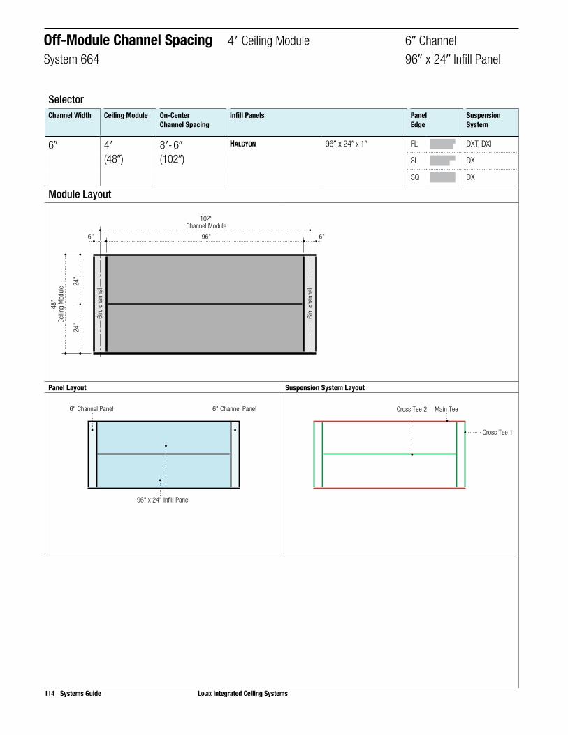
114 Systems Guide LOGIX Integrated Ceiling Systems
Panel Layout Suspension System Layout
96" x 24" Infill Panel
6" Channel Panel 6" Channel Panel
Cross Tee 1
Main TeeCross Tee 2
Module Layout
24"
24"
96"6" 6"
102"Channel Module
48"
Ceilin
g M
odul
e
6in.
cha
nnel
6in.
cha
nnel
SelectorChannel Width Ceiling Module On-Center
Channel SpacingInfill Panels Panel
EdgeSuspension System
6! 4"(48!)
8"- 6!(102!)
HALCYON 96! x 24! x 1! FL DXT, DXI
SL DX
SQ DX
Off-Module Channel Spacing 4" Ceiling Module 6! ChannelSystem 664 96! x 24! Infill Panel

Suspension System EstimatorLength Sq. Ft. Main Tee
Usage Per Sq. Ft.Cross Tee 1Usage Per Sq. Ft.
Cross Tee 2Usage Per Sq. Ft.
System Module 102! 34 0.25 0.24 0.12
Note: Multiply the ceiling area (SF) by the Usage Factor (UF). This calculation will determine lineal footage of suspension system components required. Please refer to the front of this catalogue or IC592 for stabilizer bar usage.
Step 3. Select Corresponding Grid for Selected Panels
FL/FLB SL/SLT SQ
Edge Item No. Edge Item No. Edge Item No.
Infill Panels HALCYON 96! x 24! x 1! FL ¨ 98197 SL ¨ 99269 SQ ¨ 98351
Channel Panels HALCYON 6! x 48! x 1! FL ¨ 98198 SL ¨ 99271 SQ ¨ 97227
PANZ Metal Panels, Solid 6! x 48! FL ¨ 256820 SL ¨ 256819 SQ ¨ 256768
Panz Metal Panels, Perf C116 6! x 48! FL ¨ 256062 SL ¨ 257248 SQ ¨ 256397
Panz Metal Panels, Perf C116D 6! x 48! FL ¨ 257585 SL ¨ 257584 SQ ¨ 257406
Qty Item No. Qty Item No. Qty Item No.
Suspension Systems
CENTRICITEE DXT Main Tee ¨ DXT24
Cross Tee 1 2 ¨ DXT424
Cross Tee 2 1 ¨ DXT824
IDENTITEE DXI Main Tee ¨ DXI24
Cross Tee 1 2 ¨ DXI424
Cross Tee 2 1 ¨ DXI824
DONN DX Main Tee ¨ DX/DXL24 ¨ DX/DXL24
Cross Tee 1 2 ¨ DX422 2 ¨ DX422
Cross Tee 2 1 ¨ DX824 1 ¨ DX824
Order Information 4" Ceiling Module 6! ChannelSystem 664 96! x 24! Infill Panel
LOGIX Integrated Ceiling Systems Systems Guide 115
Step 1. Select Panels Step 2. Select Edge for Panels

116 Systems Guide LOGIX Integrated Ceiling Systems
Panel Layout Suspension System Layout
96" x 48" Infill Panel
6" Channel Panel 6" Channel Panel
Cross Tee 1
Main Tee
Module Layout
96"6" 6"
102"Channel Module
48"
Ceilin
g M
odul
e
6in.
cha
nnel
6in.
cha
nnel
SelectorChannel Width Ceiling Module On-Center
Channel SpacingInfill Panels Panel
EdgeSuspension System
6! 4"(48!)
8"- 6!(102!)
HALCYON 96! x 48! x 1! SL DX
SQ DX
Off-Module Channel Spacing 4" Ceiling Module 6! ChannelSystem 979 96! x 48! Infill Panel

Suspension System EstimatorLength Sq. Ft. Main Tee
Usage Per Sq. Ft.Cross Tee 1Usage Per Sq. Ft.
System Module 102! 34 0.25 0.24
Note: Multiply the ceiling area (SF) by the Usage Factor (UF). This calculation will determine lineal footage of suspension system components required. Please refer to the front of this catalogue or IC592 for stabilizer bar usage.
Step 3. Select Corresponding Grid for Selected Panels
FL/FLB SL/SLT SQ
Edge Item No. Edge Item No. Edge Item No.
Infill Panels HALCYON 96! x 48! x 1! SL ¨ 98483 SQ ¨ 98481
Channel Panels HALCYON 6! x 48! x 1! SL ¨ 99271 SQ ¨ 97227
PANZ Metal Panels, Solid 6! x 48! SL ¨ 256819 SQ ¨ 256768
Panz Metal Panels, Perf C116 6! x 48! SL ¨ 257248 SQ ¨ 256397
Panz Metal Panels, Perf C116D 6! x 48! SL ¨ 257584 SQ ¨ 257406
Qty Item No. Qty Item No. Qty Item No.
Suspension Systems
DONN DX Main Tee ¨ DX/DXL24 ¨ DX/DXL24
Cross Tee 1 2 ¨ DX422 2 ¨ DX422
Order Information 4" Ceiling Module 6! ChannelSystem 979 96! x 48! Infill Panel
LOGIX Integrated Ceiling Systems Systems Guide 117
Step 1. Select Panels Step 2. Select Edge for Panels

118 Systems Guide LOGIX Integrated Ceiling Systems
Panel Layout Suspension System Layout
24" x 24" Infill Panel 24" x 24" Infill Panel
6" Channel Panel 6" Channel Panel
Cross Tee 1
Main Tee
Cross Tee 3
Cross Tee 2
Module Layout
24"
24"
6" 6"24" 24" 24" 24"
102"Channel Module
48"
Ceilin
g M
odul
e
6in.
cha
nnel
6in.
cha
nnel
SelectorChannel Width Ceiling Module On-Center
Channel SpacingInfill Panels Panel
EdgeSuspension System
6! 4"(48!)
8"- 6!(102!)
HALCYON 24! x 24! x 1! FL DXT, DXI
SL DX
SQ DX, DXT
MARS 24! x 24! x 3/4! FLB DXT, DXI
SLT DX
SQ DX, DXT
MARS High-NRC 24! x 24! x 7/8! FLB DXT, DXI
SLT DX
SQ DX, DXT
PANZ Metal Panels, Solid 24! x 24! FL DXT, DXI
Off-Module Channel Spacing 4" Ceiling Module 6! ChannelSystem 776 24! x 24! Infill Panel

Suspension System EstimatorLength Sq. Ft. Main Tee
Usage Per Sq. Ft.Cross Tee 1Usage Per Sq. Ft.
Cross Tee 2Usage Per Sq. Ft.
Cross Tee 3Usage Per Sq. Ft.
System Module 102! 34 0.25 0.24 0.35 0.24
Note: Multiply the ceiling area (SF) by the Usage Factor (UF). This calculation will determine lineal footage of suspension system components required. Please refer to the front of this catalogue or IC592 for stabilizer bar usage.
FL/FLB SL/SLT SQ
Edge Item No. Edge Item No. Edge Item No.
Infill Panels HALCYON 24! x 24! x 1! FL ¨ 98225 SL ¨ 98223 SQ ¨ 98221
MARS 24! x 24! x 3/4! FLB ¨ 86985 SLT ¨ 86785 SQ ¨ 86185
MARS High-NRC 24! x 24! x 7/8! FLB ¨ 87100 SLT ¨ 87200 SQ ¨ 86100
PANZ Metal Panels, Solid 24! x 24! FL ¨ 275616
Channel Panels HALCYON 6! x 48! x 1! FL ¨ 98198 SL ¨ 99271 SQ ¨ 97227
MARS 6! x 48! x 3/4! FLB ¨ 88887 SLT ¨ 86542 SQ ¨ 86325
MARS High-NRC 6! x 48! x 7/8! FLB ¨ 86331 SLT ¨ 86442 SQ ¨ 86404
PANZ Metal Panels, Solid 6! x 48! FL ¨ 256820 SL ¨ 256819 SQ ¨ 256768
Panz Metal Panels, Perf C116 6! x 48! FL ¨ 256062 SL ¨ 257248 SQ ¨ 256397
Panz Metal Panels, Perf C116D 6! x 48! FL ¨ 257585 SL ¨ 257584 SQ ¨ 257406
Qty Item No. Qty Item No. Qty Item No.
Suspension Systems
CENTRICITEE DXT Main Tee ¨ DXT24 ¨ DXT24
Cross Tee 1 2 ¨ DXT424 2 ¨ DXT424
Cross Tee 2 3 ¨ DXT424 3 ¨ DXT424
Cross Tee 3 4 ¨ DXT222 4 ¨ DXT222
IDENTITEE DXI Main Tee ¨ DXI24
Cross Tee 1 2 ¨ DXI424
Cross Tee 2 3 ¨ DXI424
Cross Tee 3 4 ¨ DXI222
DONN DX Main Tee ¨ DX/DXL24 ¨ DX/DXL24
Cross Tee 1 2 ¨ DX422 2 ¨ DX422
Cross Tee 2 3 ¨ DX422 3 ¨ DX422
Cross Tee 3 4 ¨ DX216 4 ¨ DX216
Order Information 4" Ceiling Module 6! ChannelSystem 776 24! x 24! Infill Panel
Step 3. Select Corresponding Grid for Selected Panels
LOGIX Integrated Ceiling Systems Systems Guide 119
Step 1. Select Panels Step 2. Select Edge for Panels

120 Systems Guide LOGIX Integrated Ceiling Systems
Panel Layout
120" x 24" Infill Panel
6" Channel Panel 6" Channel Panel
Module Layout
24"
24"
120"6" 6"
126"Channel Module
48"
Ceilin
g M
odul
e
6in.
cha
nnel
6in.
cha
nnel
SelectorChannel Width Ceiling Module On-Center
Channel SpacingInfill Panels Panel
EdgeSuspension System
6! 4"(48!)
10"- 6!(126!)
HALCYON 120! x 24! x 1! FL DXT, DXI
Off-Module Channel Spacing 4" Ceiling Module 6! ChannelSystem 383 120! x 24! Infill Panel
Suspension System Layout
Cross Tee 1
Main TeeCross Tee 2

LOGIX Integrated Ceiling Systems Systems Guide 121
Suspension System EstimatorLength Sq. Ft. Main Tee
Usage Per Sq. Ft.Cross Tee 1Usage Per Sq. Ft.
Cross Tee 2Usage Per Sq. Ft.
System Module 126! 34 0.25 0.19 0.24
Note: Multiply the ceiling area (SF) by the Usage Factor (UF). This calculation will determine lineal footage of suspension system components required. Please refer to the front of this catalogue or IC592 for stabilizer bar usage.
Step 3. Select Corresponding Grid for Selected Panels
FL/FLB SL/SLT SQ
Edge Item No. Edge Item No. Edge Item No.
Infill Panels HALCYON 120! x 24! x 1! FL ¨ 99213
Channel Panels HALCYON 6! x 48! x 1! FL ¨ 98198
PANZ Metal Panels, Solid 6! x 48! FL ¨ 256820
Panz Metal Panels, Perf C116 6! x 48! FL ¨ 256062
Panz Metal Panels, Perf C116D 6! x 48! FL ¨ 257585
Qty Item No. Qty Item No. Qty Item No.
Suspension Systems
CENTRICITEE DXT Main Tee ¨ DXT24SP110
Cross Tee 1 2 ¨ DXT424
Cross Tee 2 1 ¨ DXT1024
IDENTITEE DXI Main Tee ¨ DXI24SP110
Cross Tee 1 2 ¨ DXI424
Cross Tee 2 1 ¨ DXI1024
Order Information 4" Ceiling Module 6! ChannelSystem 383 120! x 24! Infill Panel
Step 1. Select Panels Step 2. Select Edge for Panels

122 Systems Guide LOGIX Integrated Ceiling Systems
Panel Layout Suspension System Layout
30" x 60" Infill Panel
4" Channel Panel 4" Channel Panel
Cross Tee 1
Main Tee
Cross Tee 2
Module Layout
30" 30"4" 4"
64"Channel Module
60"
Ceilin
g M
odul
e
4in.
cha
nnel
4in.
cha
nnel
SelectorChannel Width Ceiling Module On-Center
Channel SpacingInfill Panels Panel
EdgeSuspension System
4! 5"(60!)
5"- 4!(64!)
HALCYON 30! x 60! x 1! FL DXT, DXI
SL DX
SQ DX
MARS 30! x 60! x 3/4! FLB DXT, DXI
SLT DX
SQ DX
MARS High-NRC 30! x 60! x 7/8! FLB DXT, DXI
SLT DX
SQ DX
PANZ Metal Panels, Solid 30! x 60! FL DXT, DXI
Off-Module Channel Spacing 5" Ceiling Module 4! ChannelSystem 697 30! x 60! Infill Panel

Suspension System EstimatorLength Sq. Ft. Main Tee
Usage Per Sq. Ft.Cross Tee 1Usage Per Sq. Ft.
Cross Tee 2Usage Per Sq. Ft.
System Module 64! 26.667 0.20 0.38 0.19
Note: Multiply the ceiling area (SF) by the Usage Factor (UF). This calculation will determine lineal footage of suspension system components required. Please refer to the front of this catalogue or IC592 for stabilizer bar usage.
Step 3. Select Corresponding Grid for Selected Panels
FL/FLB SL/SLT SQ
Edge Item No. Edge Item No. Edge Item No.
Infill Panels HALCYON 30! x 60! x 1! FL ¨ 98336 SL ¨ 99270 SQ ¨ 97266
MARS 30! x 60! x 3/4! FLB ¨ 86267 SLT ¨ 86564 SQ ¨ 86536
MARS High-NRC 30! x 60! x 7/8! FLB ¨ 86497 SLT ¨ 86466 SQ ¨ 86429
PANZ Metal Panels, Solid 30! x 60! FL ¨ 212201
Channel Panels HALCYON 4! x 60! x 1! FL ¨ 97461 SL ¨ 97431 SQ ¨ 97403
MARS 4! x 60! x 3/4! FLB ¨ 86569 SLT ¨ 86541 SQ ¨ 86515
MARS High-NRC 4! x 60! x 7/8! FLB ¨ 86476 SLT ¨ 86441 SQ ¨ 86403
Qty Item No. Qty Item No. Qty Item No.
Suspension Systems
CENTRICITEE DXT Main Tee ¨ DXT24SP107
Cross Tee 1 2 ¨ DXT524
Cross Tee 2 1 ¨ DXT524
IDENTITEE DXI Main Tee ¨ DXI24SP107
Cross Tee 1 2 ¨ DXI524
Cross Tee 2 1 ¨ DXI524
DONN DX Main Tee ¨ DX24SP107 ¨ DX24SP107
Cross Tee 1 2 ¨ DX524 2 ¨ DX524
Cross Tee 2 1 ¨ DX524 1 ¨ DX524
Order Information 5" Ceiling Module 4! ChannelSystem 697 30! x 60! Infill Panel
LOGIX Integrated Ceiling Systems Systems Guide 123
Step 1. Select Panels Step 2. Select Edge for Panels

124 Systems Guide LOGIX Integrated Ceiling Systems
Panel Layout Suspension System Layout
30" x 60" Infill Panel
6" Channel Panel 6" Channel Panel
Cross Tee 1
Main Tee
Cross Tee 2
Module Layout
30" 30"6" 6"
66"Channel Module
60"
Ceilin
g M
odul
e
6in.
cha
nnel
6in.
cha
nnel
SelectorChannel Width Ceiling Module On-Center
Channel SpacingInfill Panels Panel
EdgeSuspension System
6! 5"(60!)
5"- 6!(66!)
HALCYON 30! x 60! x 1! FL DXT, DXI
SL DX
SQ DX
MARS 30! x 60! x 3/4! FLB DXT, DXI
SLT DX
SQ DX
MARS High-NRC 30! x 60! x 7/8! FLB DXT, DXI
SLT DX
SQ DX
PANZ Metal Panels, Solid 30! x 60! FL DXT, DXI
Off-Module Channel Spacing 5" Ceiling Module 6! ChannelSystem 369 30! x 60! Infill Panel

Suspension System EstimatorLength Sq. Ft. Main Tee
Usage Per Sq. Ft.Cross Tee 1Usage Per Sq. Ft.
Cross Tee 2Usage Per Sq. Ft.
System Module 66! 27.5 0.20 0.36 0.18
Note: Multiply the ceiling area (SF) by the Usage Factor (UF). This calculation will determine lineal footage of suspension system components required. Please refer to the front of this catalogue or IC592 for stabilizer bar usage.
FL/FLB SL/SLT SQ
Edge Item No. Edge Item No. Edge Item No.
Infill Panels HALCYON 30! x 60! x 1! FL ¨ 98336 SL ¨ 99270 SQ ¨ 97266
MARS 30! x 60! x 3/4! FLB ¨ 86267 SLT ¨ 86564 SQ ¨ 86536
MARS High-NRC 30! x 60! x 7/8! FLB ¨ 86497 SLT ¨ 86466 SQ ¨ 86429
PANZ Metal Panels, Solid 30! x 60! FL ¨ 212201
Channel Panels HALCYON 6! x 60! x 1! FL ¨ 98199 SL ¨ 99272 SQ ¨ 97228
MARS 6! x 60! x 3/4! FLB ¨ 86835 SLT ¨ 86543 SQ ¨ 86507
MARS High-NRC 6! x 60! x 7/8! FLB ¨ 86333 SLT ¨ 86443 SQ ¨ 86145
PANZ Metal Panels, Solid 6! x 60! FL ¨ 258036 SL ¨ 257972 SQ ¨ 257586
Panz Metal Panels, Perf C116 6! x 60! FL ¨ 259228 SL ¨ 259010 SQ ¨ 259009
Panz Metal Panels, Perf C116D 6! x 60! FL ¨ 259353 SL ¨ 259344 SQ ¨ 259308
Qty Item No. Qty Item No. Qty Item No.
Suspension Systems
CENTRICITEE DXT Main Tee ¨ DXT24
Cross Tee 1 2 ¨ DXT524
Cross Tee 2 1 ¨ DXT524
IDENTITEE DXI Main Tee ¨ DXI24
Cross Tee 1 2 ¨ DXI524
Cross Tee 2 1 ¨ DXI524
DONN DX Main Tee ¨ DX/DXL24 ¨ DX/DXL24
Cross Tee 1 2 ¨ DX524 2 ¨ DX524
Cross Tee 2 1 ¨ DX524 1 ¨ DX524
Order Information 5" Ceiling Module 6! ChannelSystem 369 30! x 60! Infill Panel
Step 3. Select Corresponding Grid for Selected Panels
LOGIX Integrated Ceiling Systems Systems Guide 125
Step 1. Select Panels Step 2. Select Edge for Panels

126 Systems Guide LOGIX Integrated Ceiling Systems
Panel Layout Suspension System Layout
30" x 30" Infill Panel
4" Channel Panel 4" Channel Panel
Cross Tee 1
Main TeeCross Tee 3
Cross Tee 2
Module Layout
30" 30"4" 4"
30"
30"
64"Channel Module
60"
Ceilin
g M
odul
e
4in.
cha
nnel
4in.
cha
nnel
SelectorChannel Width Ceiling Module On-Center
Channel SpacingInfill Panels Panel
EdgeSuspension System
4! 5"(60!)
5"- 4!(64!)
HALCYON 30! x 30! x 1! FL DXT, DXI
SL DX
SQ DX
MARS 30! x 30! x 3/4! FLB DXT, DXI
SLT DX
SQ DX
MARS High-NRC 30! x 30! x 7/8! FLB DXT, DXI
SLT DX
SQ DX
PANZ Metal Panels, Solid 30! x 30! FL DXT, DXI
Off-Module Channel Spacing 5" Ceiling Module 4! ChannelSystem 378 30! x 30! Infill Panel

Suspension System EstimatorLength Sq. Ft. Main Tee
Usage Per Sq. Ft.Cross Tee 1Usage Per Sq. Ft.
Cross Tee 2Usage Per Sq. Ft.
System Module 66! 27.5 0.20 0.36 0.18
Note: Multiply the ceiling area (SF) by the Usage Factor (UF). This calculation will determine lineal footage of suspension system components required. Please refer to the front of this catalogue or IC592 for stabilizer bar usage.
Step 3. Select Corresponding Grid for Selected Panels
FL/FLB SL/SLT SQ
Edge Item No. Edge Item No. Edge Item No.
Infill Panels HALCYON 30! x 30! x 1! FL ¨ 98335 SL ¨ 98333 SQ ¨ 98331
MARS 30! x 30! x 3/4! FLB ¨ 86830 SLT ¨ 86875 SQ ¨ 86815
MARS High-NRC 30! x 30! x 7/8! FLB ¨ 86400 SLT ¨ 86500 SQ ¨ 86426
PANZ Metal Panels, Solid 30! x 30! FL ¨ 212123
Channel Panels HALCYON 4! x 60! x 1! FL ¨ 97461 SL ¨ 97431 SQ ¨ 97403
MARS 4! x 60! x 3/4! FLB ¨ 86569 SLT ¨ 86541 SQ ¨ 86515
MARS High-NRC 4! x 60! x 7/8! FLB ¨ 86476 SLT ¨ 86441 SQ ¨ 86403
Qty Item No. Qty Item No. Qty Item No.
Suspension Systems
CENTRICITEE DXT Main Tee ¨ DXT24SP107
Cross Tee 1 2 ¨ DXT524
Cross Tee 2 1 ¨ DXT524
Cross Tee 3 1 ¨ DXT3022
IDENTITEE DXI Main Tee ¨ DXI24SP107
Cross Tee 1 2 ¨ DXI524
Cross Tee 2 1 ¨ DXI524
Cross Tee 3 1 ¨ DXI3022
DONN DX Main Tee ¨ DX124SP107 ¨ DX124SP107
Cross Tee 1 2 ¨ DX524 2 ¨ DX524
Cross Tee 2 1 ¨ DX524 1 ¨ DX524
Cross Tee 3 1 ¨ DX3016 1 ¨ DX3016
Order Information 5" Ceiling Module 4! ChannelSystem 378 30! x 30! Infill Panel
LOGIX Integrated Ceiling Systems Systems Guide 127
Step 1. Select Panels Step 2. Select Edge for Panels

128 Systems Guide LOGIX Integrated Ceiling Systems
Panel Layout Suspension System Layout
30" x 30" Infill Panel
6" Channel Panel 6" Channel Panel
Cross Tee 1
Main TeeCross Tee 3
Cross Tee 2
Module Layout
30" 30"6" 6"
30"
30"
66"Channel Module
60"
Ceilin
g M
odul
e
6in.
cha
nnel
6in.
cha
nnel
SelectorChannel Width Ceiling Module On-Center
Channel SpacingInfill Panels Panel
EdgeSuspension System
6! 5"(60!)
5"- 6!(66!)
HALCYON 30! x 30! x 1! FL DXT, DXI
SL DX
SQ DX
MARS 30! x 30! x 3/4! FLB DXT, DXI
SLT DX
SQ DX
MARS High-NRC 30! x 30! x 7/8! FLB DXT, DXI
SLT DX
SQ DX
PANZ Metal Panels, Solid 30! x 30! FL DXT, DXI
Off-Module Channel Spacing 5" Ceiling Module 6! ChannelSystem 642 30! x 30! Infill Panel

Suspension System EstimatorLength Sq. Ft. Main Tee
Usage Per Sq. Ft.Cross Tee 1Usage Per Sq. Ft.
Cross Tee 2Usage Per Sq. Ft.
Cross Tee 3Usage Per Sq. Ft.
System Module 66! 27.5 0.20 0.36 0.18 0.18
Note: Multiply the ceiling area (SF) by the Usage Factor (UF). This calculation will determine lineal footage of suspension system components required. Please refer to the front of this catalogue or IC592 for stabilizer bar usage.
FL/FLB SL/SLT SQ
Edge Item No. Edge Item No. Edge Item No.
Infill Panels HALCYON 30! x 30! x 1! FL ¨ 98335 SL ¨ 98333 SQ ¨ 98331
MARS 30! x 30! x 3/4! FLB ¨ 86830 SLT ¨ 86875 SQ ¨ 86815
MARS High-NRC 30! x 30! x 7/8! FLB ¨ 86400 SLT ¨ 86500 SQ ¨ 86426
PANZ Metal Panels, Solid 30! x 30! FL ¨ 212123
Channel Panels HALCYON 6! x 60! x 1! FL ¨ 98199 SL ¨ 99272 SQ ¨ 97228
MARS 6! x 60! x 3/4! FLB ¨ 86835 SLT ¨ 86543 SQ ¨ 86507
MARS High-NRC 6! x 60! x 7/8! FLB ¨ 86333 SLT ¨ 86443 SQ ¨ 86145
PANZ Metal Panels, Solid 6! x 60! FL ¨ 258036 SL ¨ 257972 SQ ¨ 257586
Panz Metal Panels, Perf C116 6! x 60! FL ¨ 259228 SL ¨ 259010 SQ ¨ 259009
Panz Metal Panels, Perf C116D 6! x 60! FL ¨ 259353 SL ¨ 259344 SQ ¨ 259308
Qty Item No. Qty Item No. Qty Item No.
Suspension Systems
CENTRICITEE DXT Main Tee ¨ DXT24
Cross Tee 1 2 ¨ DXT524
Cross Tee 2 1 ¨ DXT524
Cross Tee 3 2 ¨ DXT3022
IDENTITEE DXI Main Tee ¨ DXI24
Cross Tee 1 2 ¨ DXI524
Cross Tee 2 1 ¨ DXI524
Cross Tee 3 2 ¨ DXI3022
DONN DX Main Tee ¨ DX/DXL24 ¨ DX/DXL24
Cross Tee 1 2 ¨ DX524 2 ¨ DX524
Cross Tee 2 1 ¨ DX524 1 ¨ DX524
Cross Tee 3 2 ¨ DX3016 2 ¨ DX3016
Order Information 5" Ceiling Module 6! ChannelSystem 642 30! x 30! Infill Panel
Step 3. Select Corresponding Grid for Selected Panels
LOGIX Integrated Ceiling Systems Systems Guide 129
Step 1. Select Panels Step 2. Select Edge for Panels

130 Systems Guide LOGIX Integrated Ceiling Systems
Panel Layout Suspension System Layout
24" x 48" Infill Panel
4" Channel Panel 4" Channel Panel
Cross Tee 1
Main TeeCross Tee 2
Module Layout
24"
24"
24"
48"4" 4"
52"Channel Module
72"
Ceilin
g M
odul
e
4in.
cha
nnel
4in.
cha
nnel
SelectorChannel Width Ceiling Module On-Center
Channel SpacingInfill Panels Panel
EdgeSuspension System
4! 6"(72!)
4"- 4!(52!)
HALCYON 24! x 48! x 1! FL DXT, DXI
SL DX
SQ DX
MARS 24! x 48! x 3/4! FLB DXT, DXI
SLT DX
SQ DX
MARS High-NRC 24! x 48! x 7/8! FLB DXT, DXI
SLT DX
SQ DX
PANZ Metal Panels, Solid 24! x 48! FL DXT, DXI
Off-Module Channel Spacing 5" Ceiling Module 4! ChannelSystem 859 24! x 48! Infill Panel
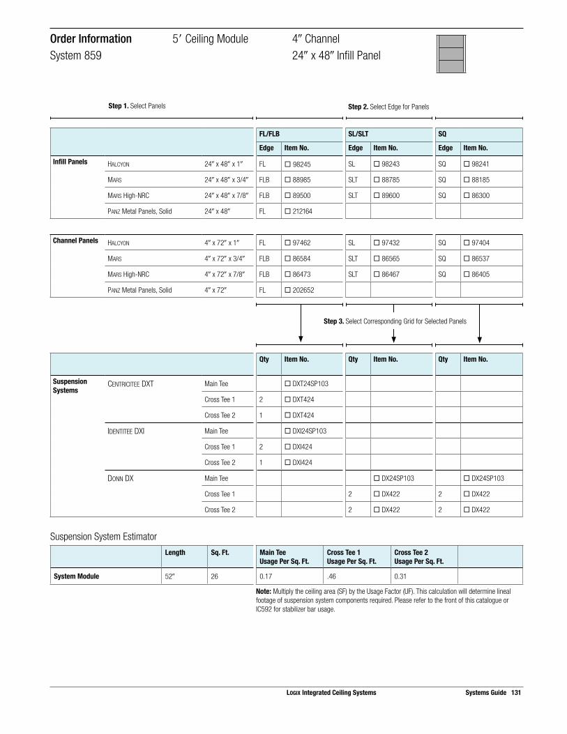
Suspension System EstimatorLength Sq. Ft. Main Tee
Usage Per Sq. Ft.Cross Tee 1Usage Per Sq. Ft.
Cross Tee 2Usage Per Sq. Ft.
System Module 52! 26 0.17 .46 0.31
Note: Multiply the ceiling area (SF) by the Usage Factor (UF). This calculation will determine lineal footage of suspension system components required. Please refer to the front of this catalogue or IC592 for stabilizer bar usage.
FL/FLB SL/SLT SQ
Edge Item No. Edge Item No. Edge Item No.
Infill Panels HALCYON 24! x 48! x 1! FL ¨ 98245 SL ¨ 98243 SQ ¨ 98241
MARS 24! x 48! x 3/4! FLB ¨ 88985 SLT ¨ 88785 SQ ¨ 88185
MARS High-NRC 24! x 48! x 7/8! FLB ¨ 89500 SLT ¨ 89600 SQ ¨ 86300
PANZ Metal Panels, Solid 24! x 48! FL ¨ 212164
Channel Panels HALCYON 4! x 72! x 1! FL ¨ 97462 SL ¨ 97432 SQ ¨ 97404
MARS 4! x 72! x 3/4! FLB ¨ 86584 SLT ¨ 86565 SQ ¨ 86537
MARS High-NRC 4! x 72! x 7/8! FLB ¨ 86473 SLT ¨ 86467 SQ ¨ 86405
PANZ Metal Panels, Solid 4! x 72! FL ¨ 202652
Qty Item No. Qty Item No. Qty Item No.
Suspension Systems
CENTRICITEE DXT Main Tee ¨ DXT24SP103
Cross Tee 1 2 ¨ DXT424
Cross Tee 2 1 ¨ DXT424
IDENTITEE DXI Main Tee ¨ DXI24SP103
Cross Tee 1 2 ¨ DXI424
Cross Tee 2 1 ¨ DXI424
DONN DX Main Tee ¨ DX24SP103 ¨ DX24SP103
Cross Tee 1 2 ¨ DX422 2 ¨ DX422
Cross Tee 2 2 ¨ DX422 2 ¨ DX422
Order Information 5" Ceiling Module 4! ChannelSystem 859 24! x 48! Infill Panel
Step 3. Select Corresponding Grid for Selected Panels
LOGIX Integrated Ceiling Systems Systems Guide 131
Step 1. Select Panels Step 2. Select Edge for Panels

132 Systems Guide LOGIX Integrated Ceiling Systems
Panel Layout Suspension System Layout
24" x 48" Infill Panel
6" Channel Panel 6" Channel Panel
Cross Tee 1
Main TeeCross Tee 2
Module Layout
24"
24"
24"
48"6" 6"
54"Channel Module
72"
Ceilin
g M
odul
e
6in.
cha
nnel
6in.
cha
nnel
SelectorChannel Width Ceiling Module On-Center
Channel SpacingInfill Panels Panel
EdgeSuspension System
6! 6"(72!)
4"- 6!(54!)
HALCYON 24! x 48! x 1! FL DXT, DXI
SL DX
SQ DX
MARS 24! x 48 x 3/4! FLB DXT, DXI
SLT DX
SQ DX
MARS High-NRC 24! x 48! x 7/8! FLB DXT, DXI
SLT DX
SQ DX
PANZ Metal Panels, Solid 24! x 48! FL DXT, DXI
Off-Module Channel Spacing 6" Ceiling Module 6! ChannelSystem 824 24! x 48! Infill Panel

Suspension System EstimatorLength Sq. Ft. Main Tee
Usage Per Sq. Ft.Cross Tee 1Usage Per Sq. Ft.
Cross Tee 2Usage Per Sq. Ft.
System Module 54! 27 0.17 0.30 0.30
Note: Multiply the ceiling area (SF) by the Usage Factor (UF). This calculation will determine lineal footage of suspension system components required. Please refer to the front of this catalogue or IC592 for stabilizer bar usage.
FL/FLB SL/SLT SQ
Edge Item No. Edge Item No. Edge Item No.
Infill Panels HALCYON 24! x 48! x 1! FL ¨ 98245 SL ¨ 98243 SQ ¨ 98241
MARS 24! x 48! x 3/4! FLB ¨ 88985 SLT ¨ 88785 SQ ¨ 88185
MARS High-NRC 24! x 48! x 7/8! FLB ¨ 89500 SLT ¨ 89600 SQ ¨ 86300
PANZ Metal Panels, Solid 24! x 48! FL ¨ 212164
Channel Panels HALCYON 6! x 72! x 1! FL ¨ 97574 SL ¨ 97433 SQ ¨ 97405
MARS 6! x 72! x 3/4! FLB ¨ 86567 SLT ¨ 86566 SQ ¨ 86538
MARS High-NRC 6! x 72! x 7/8! FLB ¨ 86474 SLT ¨ 86468 SQ ¨ 86406
PANZ Metal Panels, Solid 6! x 72! FL ¨ 202653
Qty Item No. Qty Item No. Qty Item No.
Suspension Systems
CENTRICITEE DXT Main Tee ¨ DXT24
Cross Tee 1 2 ¨ DXT424
Cross Tee 2 2 ¨ DXT424
IDENTITEE DXI Main Tee ¨ DXI24
Cross Tee 1 2 ¨ DXI424
Cross Tee 2 2 ¨ DXI424
DONN DX Main Tee ¨ DX/DXL24 ¨ DX/DXL24
Cross Tee 1 2 ¨ DX422 2 ¨ DX422
Cross Tee 2 2 ¨ DX422 2 ¨ DX422
Order Information 6" Ceiling Module 6! ChannelSystem 824 24! x 48! Infill Panel
Step 3. Select Corresponding Grid for Selected Panels
LOGIX Integrated Ceiling Systems Systems Guide 133
Step 1. Select Panels Step 2. Select Edge for Panels

134 Systems Guide LOGIX Integrated Ceiling Systems
Panel Layout Suspension System Layout
24" x 24" Infill Panel
4" Channel Panel 4" Channel Panel
Cross Tee 1
Main TeeCross Tee 3
Cross Tee 2
Module Layout
24"
24"
24"
24"4" 4"24"
52"Channel Module
72"
Ceilin
g M
odul
e
4in.
cha
nnel
4in.
cha
nnel
SelectorChannel Width Ceiling Module On-Center
Channel SpacingInfill Panels Panel
EdgeSuspension System
4! 6"(72!)
4"- 4!(52!)
HALCYON 24! x 24! x 1! FL DXT, DXI
SL DX
SQ DX, DXT
MARS 24! x 24! x 3/4! FLB DXT, DXI
SLT DX
SQ DX, DXT
MARS High-NRC 24! x 24! x 7/8! FLB DXT, DXI
SLT DX
SQ DX, DXT
PANZ Metal Panels, Solid 24! x 24! FL DXT, DXI
Off-Module Channel Spacing 6" Ceiling Module 4! ChannelSystem 724 24! x 24! Infill Panel

Suspension System EstimatorLength Sq. Ft. Main Tee
Usage Per Sq. Ft.Cross Tee 1Usage Per Sq. Ft.
Cross Tee 2Usage Per Sq. Ft.
Cross Tee 3Usage Per Sq. Ft.
System Module 52! 26 0.17 0.46 0.23 0.31
Note: Multiply the ceiling area (SF) by the Usage Factor (UF). This calculation will determine lineal footage of suspension system components required. Please refer to the front of this catalogue or IC592 for stabilizer bar usage.
Step 3. Select Corresponding Grid for Selected Panels
FL/FLB SL/SLT SQ
Edge Item No. Edge Item No. Edge Item No.
Infill Panels HALCYON 24! x 24! x 1! FL ¨ 98225 SL ¨ 98223 SQ ¨ 98221
MARS 24! x 24! x 3/4! FLB ¨ 86985 SLT ¨ 86785 SQ ¨ 86185
MARS High-NRC 24! x 24! x 7/8! FLB ¨ 87100 SLT ¨ 87200 SQ ¨ 86100
PANZ Metal Panels, Solid 24! x 24! FL ¨ 275616
Channel Panels HALCYON 4! x 72! x 1! FL ¨ 97462 SL ¨ 97432 SQ ¨ 97404
MARS 4! x 72! x 3/4! FLB ¨ 86584 SLT ¨ 86565 SQ ¨ 86537
MARS High-NRC 4! x 72! x 7/8! FLB ¨ 86473 SLT ¨ 86467 SQ ¨ 86405
PANZ Metal Panels, Solid 4! x 72! FL ¨ 202652
Qty Item No. Qty Item No. Qty Item No.
Suspension Systems
CENTRICITEE DXT Main Tee ¨ DXT24SP103 ¨ DXT24SP103
Cross Tee 1 2 ¨ DXT624 2 ¨ DXT624
Cross Tee 2 1 ¨ DXT624 1 ¨ DXT624
Cross Tee 3 4 ¨ DXT222 4 ¨ DXT222
IDENTITEE DXI Main Tee ¨ DXI24SP103
Cross Tee 1 2 ¨ DXI624
Cross Tee 2 1 ¨ DXI624
Cross Tee 3 4 ¨ DXI222
DONN DX Main Tee ¨ DX24SP103 ¨ DX24SP103
Cross Tee 1 2 ¨ DX624 2 ¨ DX624
Cross Tee 2 1 ¨ DX624 1 ¨ DX624
Cross Tee 3 4 ¨ DX216 4 ¨ DX216
Order Information 6" Ceiling Module 4! ChannelSystem 724 24! x 24! Infill Panel
LOGIX Integrated Ceiling Systems Systems Guide 135
Step 1. Select Panels Step 2. Select Edge for Panels

136 Systems Guide LOGIX Integrated Ceiling Systems
Panel Layout Suspension System Layout
24" x 24" Infill Panel
6" Channel Panel 6" Channel Panel
Cross Tee 1
Main TeeCross Tee 3
Cross Tee 2
Module Layout
24"
24"
24"
24"6" 6"24"
54"Channel Module
72"
Ceilin
g M
odul
e
6in.
cha
nnel
6in.
cha
nnel
SelectorChannel Width Ceiling Module On-Center
Channel SpacingInfill Panels Panel
EdgeSuspension System
6! 6"(72!)
4"- 6!(54!)
HALCYON 24! x 24! x 1! FL DXT, DXI
SL DX
SQ DX, DXT
MARS 24! x 24! x 3/4! FLB DXT, DXI
SLT DX
SQ DX, DXT
MARS High-NRC 24! x 24! x 7/8! FLB DXT, DXI
SLT DX
SQ DX, DXT
PANZ Metal Panels, Solid 24! x 24! FL DXT, DXI
Off-Module Channel Spacing 6" Ceiling Module 6! ChannelSystem 292 24! x 24! Infill Panel

Suspension System EstimatorLength Sq. Ft. Main Tee
Usage Per Sq. Ft.Cross Tee 1Usage Per Sq. Ft.
Cross Tee 2Usage Per Sq. Ft.
Cross Tee 3Usage Per Sq. Ft.
System Module 54! 27 0.17 0.44 0.22 0.30
Note: Multiply the ceiling area (SF) by the Usage Factor (UF). This calculation will determine lineal footage of suspension system components required. Please refer to the front of this catalogue or IC592 for stabilizer bar usage.
FL/FLB SL/SLT SQ
Edge Item No. Edge Item No. Edge Item No.
Infill Panels HALCYON 24! x 24! x 1! FL ¨ 98225 SL ¨ 98223 SQ ¨ 98221
MARS 24! x 24! x 3/4! FLB ¨ 86985 SLT ¨ 86785 SQ ¨ 86185
MARS High-NRC 24! x 24! x 7/8! FLB ¨ 87100 SLT ¨ 87200 SQ ¨ 86100
PANZ Metal Panels, Solid 24! x 24! FL ¨ 275616
Channel Panels HALCYON 6! x 72! x 1! FL ¨ 97574 SL ¨ 97433 SQ ¨ 97405
MARS 6! x 72! x 3/4! FLB ¨ 86567 SLT ¨ 86566 SQ ¨ 86538
MARS High-NRC 6! x 72! x 7/8! FLB ¨ 86474 SLT ¨ 86468 SQ ¨ 86406
PANZ Metal Panels, Solid 6! x 72! FL ¨ 202653
Qty Item No. Qty Item No. Qty Item No.
Suspension Systems
CENTRICITEE DXT Main Tee ¨ DXT24 ¨ DXT24
Cross Tee 1 2 ¨ DXT624 2 ¨ DXT624
Cross Tee 2 1 ¨ DXT624 1 ¨ DXT624
Cross Tee 3 4 ¨ DXT222 4 ¨ DXT222
IDENTITEE DXI Main Tee ¨ DXI24
Cross Tee 1 2 ¨ DXI624
Cross Tee 2 1 ¨ DXI624
Cross Tee 3 4 ¨ DXI222
DONN DX Main Tee ¨ DX/DXL24 ¨ DX/DXL24
Cross Tee 1 2 ¨ DX624 2 ¨ DX624
Cross Tee 2 1 ¨ DX624 1 ¨ DX624
Cross Tee 3 4 ¨ DX216 4 ¨ DX216
Order Information 6" Ceiling Module 6! ChannelSystem 292 24! x 24! Infill Panel
Step 3. Select Corresponding Grid for Selected Panels
LOGIX Integrated Ceiling Systems Systems Guide 137
Step 1. Select Panels Step 2. Select Edge for Panels

138 Systems Guide LOGIX Integrated Ceiling Systems
Panel Layout Suspension System Layout
24" x 72" Infill Panel
4" Channel Panel 4" Channel Panel
Cross Tee 1
Main Tee
Cross Tee 2
Module Layout
24"4" 4"24"
52"Channel Module
72"
Ceilin
g M
odul
e
4in.
cha
nnel
4in.
cha
nnel
SelectorChannel Width Ceiling Module On-Center
Channel SpacingInfill Panels Panel
EdgeSuspension System
4! 6"(72!)
4"- 4!(52!)
HALCYON 24! x 72! x 1! FL DXT, DXI
SL DX
SQ DX
MARS 24! x 72! x 3/4! FLB DXT, DXI
SLT DX
SQ DX
MARS High-NRC 24! x 72! x 7/8! FLB DXT, DXI
SLT DX
SQ DX
PANZ Metal Panels, Solid 24! x 72! FL DXT, DXI
Off-Module Channel Spacing 6" Ceiling Module 4! ChannelSystem 562 24! x 72! Infill Panel

Suspension System EstimatorLength Sq. Ft. Main Tee
Usage Per Sq. Ft.Cross Tee 1Usage Per Sq. Ft.
Cross Tee 2Usage Per Sq. Ft.
System Module 52! 26 0.17 0.46 0.23
Note: Multiply the ceiling area (SF) by the Usage Factor (UF). This calculation will determine lineal footage of suspension system components required. Please refer to the front of this catalogue or IC592 for stabilizer bar usage.
Step 3. Select Corresponding Grid for Selected Panels
FL/FLB SL/SLT SQ
Edge Item No. Edge Item No. Edge Item No.
Infill Panels HALCYON 24! x 72! x 1! FL ¨ 98348 SL ¨ 99268 SQ ¨ 99234
MARS 24! x 72! x 3/4! FLB ¨ 88996 SLT ¨ 86166 SQ ¨ 86223
MARS High-NRC 24! x 72! x 7/8! FLB ¨ 89670 SLT ¨ 89660 SQ ¨ 86360
PANZ Metal Panels, Solid 24! x 72! FL ¨ 212192
Channel Panels HALCYON 4! x 72! x 1! FL ¨ 97462 SL ¨ 97432 SQ ¨ 97404
MARS 4! x 72! x 3/4! FLB ¨ 86584 SLT ¨ 86565 SQ ¨ 86537
MARS High-NRC 4! x 72! x 7/8! FLB ¨ 86473 SLT ¨ 86467 SQ ¨ 86405
PANZ Metal Panels, Solid 4! x 72! FL ¨ 202652
Qty Item No. Qty Item No. Qty Item No.
Suspension Systems
CENTRICITEE DXT Main Tee ¨ DXT24SP103
Cross Tee 1 2 ¨ DXT624
Cross Tee 2 1 ¨ DXT624
IDENTITEE DXI Main Tee ¨ DXI24SP103
Cross Tee 1 2 ¨ DXI624
Cross Tee 2 1 ¨ DXI624
DONN DX Main Tee ¨ DX24SP103 ¨ DX24SP103
Cross Tee 1 2 ¨ DX624 2 ¨ DX624
Cross Tee 2 1 ¨ DX624 1 ¨ DX624
Order Information 6" Ceiling Module 4! ChannelSystem 562 24! x 72! Infill Panel
LOGIX Integrated Ceiling Systems Systems Guide 139
Step 1. Select Panels Step 2. Select Edge for Panels

140 Systems Guide LOGIX Integrated Ceiling Systems
Panel Layout Suspension System Layout
24" x 72" Infill Panel
6" Channel Panel 6" Channel Panel
Cross Tee 1
Main Tee
Cross Tee 2
Module Layout
24"6" 6"24"
54"Channel Module
72"
Ceilin
g M
odul
e
6in.
cha
nnel
6in.
cha
nnel
SelectorChannel Width Ceiling Module On-Center
Channel SpacingInfill Panels Panel
EdgeSuspension System
6! 6"(72!)
4"- 6!(54!)
HALCYON 24! x 72! x 1! FL DXT, DXI
SL DX
SQ DX
MARS 24! x 72! x 3/4! FLB DXT, DXI
SLT DX
SQ DX
MARS High-NRC 24! x 72! x 7/8! FLB DXT, DXI
SLT DX
SQ DX
PANZ Metal Panels, Solid 24! x 72! FL DXT, DXI
Off-Module Channel Spacing 4" Ceiling Module 6! ChannelSystem 643 24! x 72! Infill Panel

Suspension System EstimatorLength Sq. Ft. Main Tee
Usage Per Sq. Ft.Cross Tee 1Usage Per Sq. Ft.
Cross Tee 2Usage Per Sq. Ft.
System Module 54! 27 0.17 0.44 0.22
Note: Multiply the ceiling area (SF) by the Usage Factor (UF). This calculation will determine lineal footage of suspension system components required. Please refer to the front of this catalogue or IC592 for stabilizer bar usage.
FL/FLB SL/SLT SQ
Edge Item No. Edge Item No. Edge Item No.
Infill Panels HALCYON 24! x 72! x 1! FL ¨ 98348 SL ¨ 99268 SQ ¨ 99234
MARS 24! x 72! x 3/4! FLB ¨ 88996 SLT ¨ 86166 SQ ¨ 86223
MARS High-NRC 24! x 72! x 7/8! FLB ¨ 89670 SLT ¨ 89660 SQ ¨ 86360
PANZ Metal Panels, Solid 24! x 72! FL ¨ 212192
Channel Panels HALCYON 6! x 72! x 1! FL ¨ 97574 SL ¨ 97433 SQ ¨ 97405
MARS 6! x 72! x 3/4! FLB ¨ 86567 SLT ¨ 86566 SQ ¨ 86538
MARS High-NRC 6! x 72! x 7/8! FLB ¨ 86474 SLT ¨ 86468 SQ ¨ 86406
PANZ Metal Panels, Solid 6! x 72! FL ¨ 202653
Qty Item No. Qty Item No. Qty Item No.
Suspension Systems
CENTRICITEE DXT Main Tee ¨ DXT24
Cross Tee 1 2 ¨ DXT624
Cross Tee 2 1 ¨ DXT624
IDENTITEE DXI Main Tee ¨ DXI24
Cross Tee 1 2 ¨ DXI624
Cross Tee 2 1 ¨ DXI624
DONN DX Main Tee ¨ DX/DXL24 ¨ DX/DXL24
Cross Tee 1 2 ¨ DX624 2 ¨ DX624
Cross Tee 2 1 ¨ DX624 1 ¨ DX624
Order Information 4" Ceiling Module 6! ChannelSystem 643 24! x 72! Infill Panel
Step 3. Select Corresponding Grid for Selected Panels
LOGIX Integrated Ceiling Systems Systems Guide 141
Step 1. Select Panels Step 2. Select Edge for Panels

142 Systems Guide LOGIX Integrated Ceiling Systems
Metric Systems
100mm Channels
Overview
Channel Width
Ceiling Module
On-Center Channel Spacing
Infill Panels PANZ Metal Option System Page
InfillPanel
ChannelPanel
1000mm Ceiling Module
100mm 1000mm 1500mm 1400mm x 500mm • • 132 146-147
100mm 1000mm 1500mm 1400mm x 1000mm • 116 148-149
1200mm Ceiling Module
100mm 1200mm 1200mm 550mm x 600mm • • 121 150-151
100mm 1200mm 1200mm 1100mm x 600mm • • 134 152-153
100mm 1200mm 1200mm 1100mm x 1200mm • 105 154-155
100mm 1200mm 1300mm 1200mm x 600mm • • 112 156-157
100mm 1200mm 1300mm 1200mm x 1200mm • 108 158-159
100mm 1200mm 1900mm 1800mm x 300mm • • 141 160-161
100mm 1200mm 1900mm 1800mm x 600mm • • 139 162-163

LOGIX Integrated Ceiling Systems Systems Guide 143
Metric Systems
100mm Channels
Overview
Channel Width
Ceiling Module
On-Center Channel Spacing
Infill Panels PANZ Metal Option System Page
InfillPanel
ChannelPanel
1500mm Ceiling Module
100mm 1500mm 1500mm 700mm x 750mm • • 124 164-165
100mm 1500mm 1500mm 1400mm x 750mm • • 110 166-167
100mm 1500mm 1500mm 1400mm x 500mm • • 102 168-169
100mm 1500mm 1500mm 1400mm x 1500mm • 129 170-171

144 Systems Guide LOGIX Integrated Ceiling Systems
Metric Systems
150mm Channels
Overview
Channel Width
Ceiling Module
On-Center Channel Spacing
Infill Panels PANZ Metal, Solid System Page
InfillPanel
ChannelPanel
1000mm Ceiling Module
150mm 1000mm 1500mm 675mm x 500mm • • 136 172-173
150mm 1000mm 1500mm 1350mm x 500mm • 122 174-175
150mm 1000mm 1500mm 1350mm x 1000mm • 107 176-177
1200mm Ceiling Module
150mm 1200mm 1200mm 525mm x 600mm • 113 178-179
150mm 1200mm 1200mm 1050mm x 600mm • 109 180-181
150mm 12000mm 1200mm 1050mm x 1200mm • 101 182-183
150mm 12000mm 1350mm 600mm x 600mm • • 127 184-185
150mm 12000mm 1350mm 1200mm x 600mm • • 130 186-187
150mm 12000mm 1350mm 1200mm x 1200mm • 106 188-189
150mm 12000mm 1950mm 1800mm x 300mm • • 120 190-191
150mm 12000mm 1950mm 1800mm x 600mm • • 137 192-193

LOGIX Integrated Ceiling Systems Systems Guide 145
Metric Systems
150mm Channels
Channel Width
Ceiling Module
On-Center Channel Spacing
Infill Panels PANZ Metal, Solid System Page
InfillPanel
ChannelPanel
1500mm Ceiling Module
150mm 1500mm 1500mm 1350mm x 500mm • 114 194-195
150mm 1500mm 1500mm 1350mm x 1500mm 145 196-197
150mm 1500mm 1500mm 675mm x 750mm 143 198-199
150mm 1500mm 1500mm 1350mm x 750mm • 104 200-201
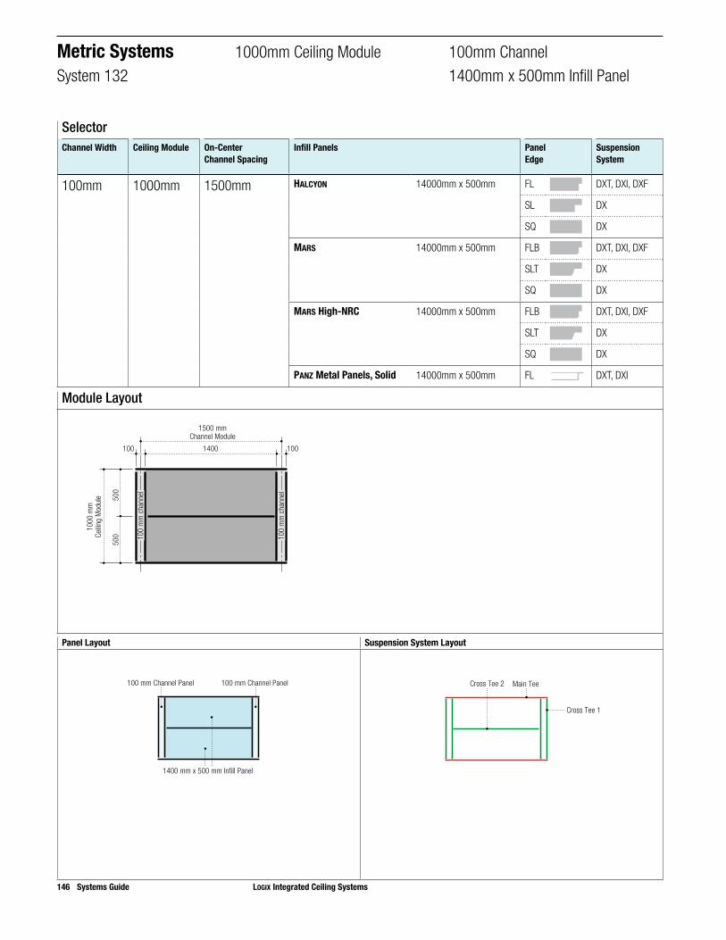
146 Systems Guide LOGIX Integrated Ceiling Systems
Panel Layout Suspension System Layout
1400 mm x 500 mm Infill Panel
100 mm Channel Panel 100 mm Channel Panel
Main Tee
Cross Tee 1
Cross Tee 2
Module Layout
1400
500
500
100 100
1500 mmChannel Module
1000
mm
Ceilin
g M
odul
e
100
mm
cha
nnel
100
mm
cha
nnel
SelectorChannel Width Ceiling Module On-Center
Channel SpacingInfill Panels Panel
EdgeSuspension System
100mm 1000mm 1500mm HALCYON 14000mm x 500mm FL DXT, DXI, DXF
SL DX
SQ DX
MARS 14000mm x 500mm FLB DXT, DXI, DXF
SLT DX
SQ DX
MARS High-NRC 14000mm x 500mm FLB DXT, DXI, DXF
SLT DX
SQ DX
PANZ Metal Panels, Solid 14000mm x 500mm FL DXT, DXI
Metric Systems 1000mm Ceiling Module 100mm ChannelSystem 132 1400mm x 500mm Infill Panel

Step 3. Select Corresponding Grid for Selected Panels
FL/FLB SL/SLT SQ
Edge Item No. Edge Item No. Edge Item No.
Infill Panels HALCYON 1400mm x 500mm FL ¨ ME97464 SL ¨ ME97437 SQ ¨ ME97408
MARS 1400mm x 500mm FLB ¨ ME86571 SLT ¨ ME86548 SQ ¨ ME86520
MARS High-NRC 1400mm x 500mm FLB ¨ ME86480 SLT ¨ ME86448 SQ ¨ ME86411
PANZ Metal Panels, Solid 1400mm x 500mm FL ¨ ME909964
Channel Panels HALCYON 100mm x 1000mm FL ¨ ME97538 SL ¨ ME97509 SQ ¨ ME97480
PANZ Metal Panels, Solid 100mm x 1000mm FL ¨ ME99946
Qty Item No. Qty Item No. Qty Item No.
Suspension Systems
CENTRICITEE DXT Main Tee ¨ MEDXT24SP205
Cross Tee 1 2 ¨ MEDXT1000
Cross Tee 2 1 ¨ MEDXT1000
Cross Tee 3 2 ¨ MEDXT700
IDENTITEE DXI Main Tee ¨ MEDXI24SP205
Cross Tee 1 2 ¨ MEDXI1000
Cross Tee 2 1 ¨ MEDXI1000
Cross Tee 3 2 ¨ MEDXI700
DONN DX Main Tee 1 ¨ MEDX24SP205 ¨ MEDX24SP205
Cross Tee 1 2 ¨ MEDX1000 2 ¨ MEDX1000
Cross Tee 2 1 ¨ MEDX1000 1 ¨ MEDX1000
Cross Tee 3 2 ¨ MEDX700 2 ¨ MEDX700
Order Information 1000mm Ceiling Module 100mm ChannelSystem 132 1400mm x 500mm Infill Panel
Suspension System EstimatorLength m2 Main Tee
Usage Per m2Cross Tee 1Usage Per m2
Cross Tee 2Usage Per m2
Cross Tee 3Usage Per m2
System Module 1500mm 1.500 1.000 1.333 0.667 0.933
Note: Multiply the ceiling area (SF) by the Usage Factor (UF). This calculation will determine lineal footage of suspension system components required. Please refer to the front of this catalogue or IC592 for stabilizer bar usage.
LOGIX Integrated Ceiling Systems Systems Guide 147
Step 1. Select Panels Step 2. Select Edge for Panels

148 Systems Guide LOGIX Integrated Ceiling Systems
Panel Layout Suspension System Layout
1400 mm x 1000 mm Infill Panel
100 mm Channel Panel 100 mm Channel Panel
Main Tee
Cross Tee 1
Module Layout
1400100 100
1500 mmChannel Module
1000
mm
Ceilin
g M
odul
e
100
mm
cha
nnel
100
mm
cha
nnel
SelectorChannel Width Ceiling Module On-Center
Channel SpacingInfill Panels Panel
EdgeSuspension System
100mm 1000mm 1500mm HALCYON 1400mm x 1000mm FL DXT, DXI, DXF
SL DX
SQ DX
Metric Systems 1000mm Ceiling Module 100mm ChannelSystem 116 1400mm x 1000mm Infill Panel
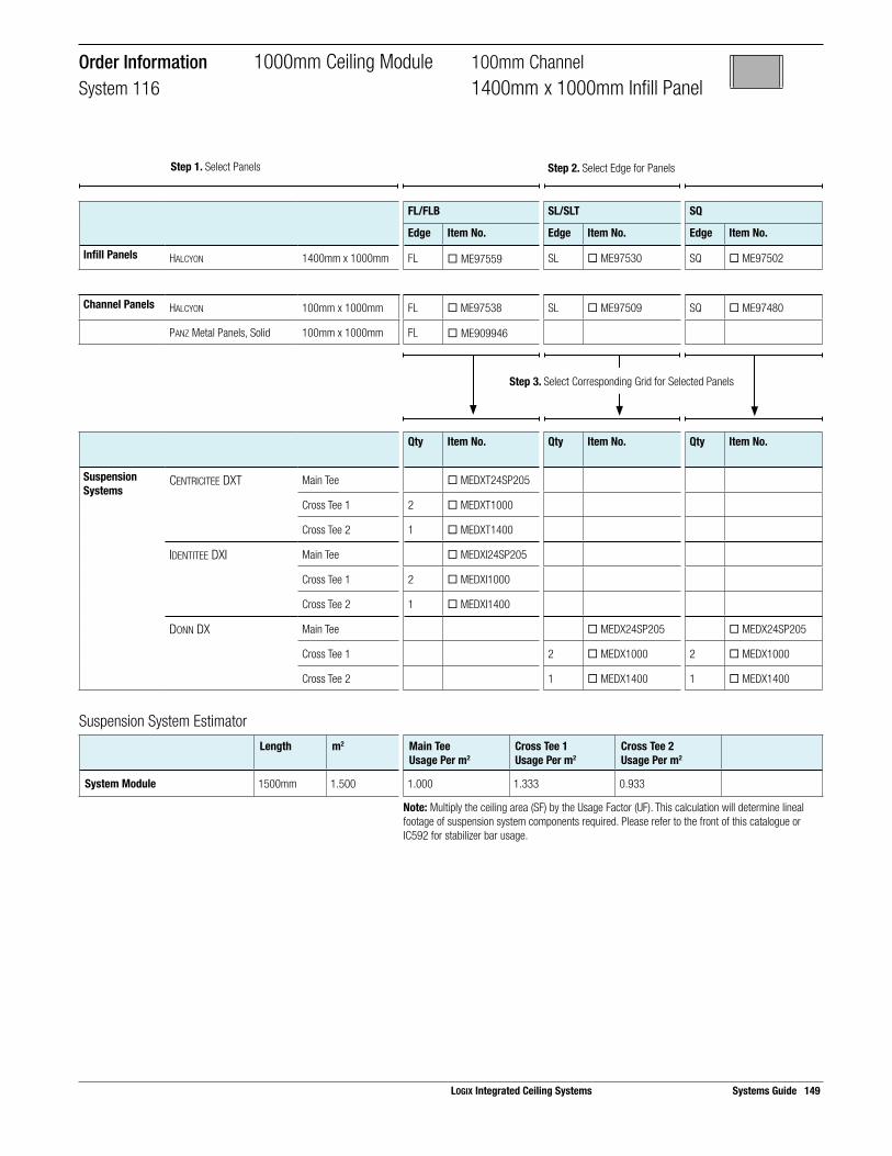
Suspension System EstimatorLength m2 Main Tee
Usage Per m2Cross Tee 1Usage Per m2
Cross Tee 2Usage Per m2
System Module 1500mm 1.500 1.000 1.333 0.933
Note: Multiply the ceiling area (SF) by the Usage Factor (UF). This calculation will determine lineal footage of suspension system components required. Please refer to the front of this catalogue or IC592 for stabilizer bar usage.
Step 3. Select Corresponding Grid for Selected Panels
FL/FLB SL/SLT SQ
Edge Item No. Edge Item No. Edge Item No.
Infill Panels HALCYON 1400mm x 1000mm FL ¨ ME97559 SL ¨ ME97530 SQ ¨ ME97502
Channel Panels HALCYON 100mm x 1000mm FL ¨ ME97538 SL ¨ ME97509 SQ ¨ ME97480
PANZ Metal Panels, Solid 100mm x 1000mm FL ¨ ME909946
Qty Item No. Qty Item No. Qty Item No.
Suspension Systems
CENTRICITEE DXT Main Tee ¨ MEDXT24SP205
Cross Tee 1 2 ¨ MEDXT1000
Cross Tee 2 1 ¨ MEDXT1400
IDENTITEE DXI Main Tee ¨ MEDXI24SP205
Cross Tee 1 2 ¨ MEDXI1000
Cross Tee 2 1 ¨ MEDXI1400
DONN DX Main Tee ¨ MEDX24SP205 ¨ MEDX24SP205
Cross Tee 1 2 ¨ MEDX1000 2 ¨ MEDX1000
Cross Tee 2 1 ¨ MEDX1400 1 ¨ MEDX1400
Order Information 1000mm Ceiling Module 100mm ChannelSystem 116 1400mm x 1000mm Infill Panel
Step 1. Select Panels Step 2. Select Edge for Panels
LOGIX Integrated Ceiling Systems Systems Guide 149
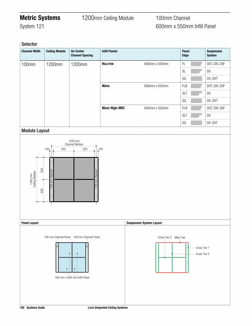
150 Systems Guide LOGIX Integrated Ceiling Systems
Panel Layout Suspension System Layout
550 mm x 600 mm Infill Panel
100 mm Channel Panel 100 mm Channel Panel
Cross Tee 3 Main Tee
Cross Tee 1
Cross Tee 2
Module Layout
600
600
550100 100550
1200 mmChannel Module
1200
mm
Ceilin
g M
odul
e
100
mm
cha
nnel
100
mm
cha
nnel
SelectorChannel Width Ceiling Module On-Center
Channel SpacingInfill Panels Panel
EdgeSuspension System
100mm 1200mm 1200mm HALCYON 600mm x 550mm FL DXT, DXI, DXF
SL DX
SQ DX, DXT
MARS 600mm x 550mm FLB DXT, DXI, DXF
SLT DX
SQ DX, DXT
MARS High-NRC 600mm x 550mm FLB DXT, DXI, DXF
SLT DX
SQ DX, DXT
Metric Systems 1200mm Ceiling Module 100mm ChannelSystem 121 600mm x 550mm Infill Panel

LOGIX Integrated Ceiling Systems Systems Guide 151
Order Information 1200mm Ceiling Module 100mm ChannelSystem 121 550mm x 600mm Infill Panel
Step 1. Select Panels Step 2. Select Edge for Panels
Step 3. Select Corresponding Grid for Selected Panels
FL/FLB SL/SLT SQ
Edge Item No. Edge Item No. Edge Item No.
Infill Panels HALCYON 550mm x 600mm FL ¨ ME97468 SL ¨ ME97440 SQ ¨ ME97413
MARS 550mm x 600mm FLB ¨ ME86574 SLT ¨ ME86552 SQ ¨ ME86524
MARS High-NRC 550mm x 600mm FLB ¨ ME86485 SLT ¨ ME86453 SQ ¨ ME86416
PANZ Metal Panels, Solid 550mm x 600mm FL ¨ ME909965
Channel Panels HALCYON 100mm x 1200mm FL ¨ ME97460 SL ¨ ME97430 SQ ¨ ME97402
MARS 100mm x 1200mm FLB ¨ ME86568 SLT ¨ ME86540 SQ ¨ ME86514
MARS High-NRC 100mm x 1200mm FLB ¨ ME86475 SLT ¨ ME86440 SQ ¨ ME86402
PANZ Metal Panels, Solid 100mm x 1200mm FL ¨ ME909947
Qty Item No. Qty Item No. Qty Item No.
Suspension Systems
CENTRICITEE DXT Main Tee 1 ¨ MEDXT24SP201 1 ¨ MEDXT24SP201
Cross Tee 1 2 ¨ MEDXT1200 2 ¨ MEDXT1200
Cross Tee 2 1 ¨ MEDXT1200 1 ¨ MEDXT1200
Cross Tee 3 2 ¨ MEDXT550 2 ¨ MEDXT550
IDENTITEE DXI Main Tee 1 ¨ MEDXI24SP201
Cross Tee 1 2 ¨ MEDXI1200
Cross Tee 2 1 ¨ MEDXI1200
Cross Tee 3 2 ¨ MEDXI550
DONN DX Main Tee 1 ¨ MEDX24SP201 1 ¨ MEDX24SP201
Cross Tee 1 2 ¨ MEDX1200 2 ¨ MEDX1200
Cross Tee 2 1 ¨ MEDX1200 1 ¨ MEDX1200
Cross Tee 3 2 ¨ MEDX550 2 ¨ MEDX550
Suspension System EstimatorLength m2 Main Tee
Usage Per m2Cross Tee 1Usage Per m2
Cross Tee 2Usage Per m2
Cross Tee 3Usage Per m2
System Module 1200mm 1.440 0.833 1.667 0.833 0.764
Note: Multiply the ceiling area (SF) by the Usage Factor (UF). This calculation will determine lineal footage of suspension system components required. Please refer to the front of this catalogue or IC592 for stabilizer bar usage.

152 Systems Guide LOGIX Integrated Ceiling Systems
Panel Layout Suspension System Layout
1100 mm x 600 mm Infill Panel
100 mm Channel Panel 100 mm Channel Panel
Cross Tee 2 Main Tee
Cross Tee 1
Module Layout
600
600
100 1001100
1200 mmChannel Module
1200
mm
Ceilin
g M
odul
e
100
mm
cha
nnel
100
mm
cha
nnel
SelectorChannel Width Ceiling Module On-Center
Channel SpacingInfill Panels Panel
EdgeSuspension System
100mm 1200mm 1200mm HALCYON 1100mm x 600mm FL DXT, DXI, DXF
SL DX
SQ DX
MARS 1100mm x 600mm FLB DXT, DXI, DXF
SLT DX
SQ DX
MARS High-NRC 1100mm x 600mm FLB DXT, DXI, DXF
SLT DX
SQ DX
PANZ Metal Panels, Solid 1100mm x 600mm FL DXT, DXI
Metric Systems 1200mm Ceiling Module 100mm ChannelSystem 134 1100mm x 600mm Infill Panel

Suspension System EstimatorLength m2 Main Tee
Usage Per m2Cross Tee 1Usage Per m2
Cross Tee 2Usage Per m2
System Module 1200mm 1.440 0.833 1.667 0.764
Note: Multiply the ceiling area (SF) by the Usage Factor (UF). This calculation will determine lineal footage of suspension system components required. Please refer to the front of this catalogue or IC592 for stabilizer bar usage.
Step 3. Select Corresponding Grid for Selected Panels
FL/FLB SL/SLT SQ
Edge Item No. Edge Item No. Edge Item No.
Infill Panels HALCYON 1100mm x 600mm FL ¨ ME97470 SL ¨ ME97444 SQ ¨ ME97416
MARS 1100mm x 600mm FLB ¨ ME86578 SLT ¨ ME86556 SQ ¨ ME86528
MARS High-NRC 1100mm x 600mm FLB ¨ ME86489 SLT ¨ ME86457 SQ ¨ ME86420
PANZ Metal Panels, Solid 1100mm x 600mm FL ¨ ME909969
Channel Panels HALCYON 100mm x 1200mm FL ¨ ME97460 SL ¨ ME97430 SQ ¨ ME97402
MARS 100mm x 1200mm FLB ¨ ME86568 SLT ¨ ME86540 SQ ¨ ME86514
MARS High-NRC 100mm x 1200mm FLB ¨ ME86475 SLT ¨ ME86440 SQ ¨ ME86402
PANZ Metal Panels, Solid 100mm x 1200mm FL ¨ ME909947
Qty Item No. Qty Item No. Qty Item No.
Suspension Systems
CENTRICITEE DXT Main Tee ¨ MEDXT24SP201
Cross Tee 1 2 ¨ MEDXT1200
Cross Tee 2 1 ¨ MEDXT1100
IDENTITEE DXI Main Tee ¨ MEDXI24SP201
Cross Tee 1 2 ¨ MEDXI1200
Cross Tee 2 1 ¨ MEDXI1100
DONN DX Main Tee ¨ MEDX24SP201 ¨ MEDX24SP201
Cross Tee 1 2 ¨ MEDX1200 2 ¨ MEDX1200
Cross Tee 2 1 ¨ MEDX1100 1 ¨ MEDX1100
Order Information 1200mm Ceiling Module 100mm ChannelSystem 134 11000mm x 600mm Infill Panel
LOGIX Integrated Ceiling Systems Systems Guide 153
Step 1. Select Panels Step 2. Select Edge for Panels

154 Systems Guide LOGIX Integrated Ceiling Systems
Panel Layout Suspension System Layout
1100 mm x 1200 mm Infill Panel
100 mm Channel Panel 100 mm Channel Panel
Main Tee
Cross Tee 1
Module Layout
100 1001100
1200 mmChannel Module
1200
mm
Ceilin
g M
odul
e
100
mm
cha
nnel
100
mm
cha
nnel
SelectorChannel Width Ceiling Module On-Center
Channel SpacingInfill Panels Panel
EdgeSuspension System
110mm 1200mm 1200mm HALCYON 1100mm x 1200mm FL DXT, DXI, DXF
SL DX
SQ DX
Metric Systems 1200mm Ceiling Module 100mm ChannelSystem 105 1100mm x 1200mm Infill Panel

Suspension System EstimatorLength m2 Main Tee
Usage Per m2Cross Tee 1Usage Per m2
System Module 1200mm 1.440 0.833 1.667
Note: Multiply the ceiling area (SF) by the Usage Factor (UF). This calculation will determine lineal footage of suspension system components required. Please refer to the front of this catalogue or IC592 for stabilizer bar usage.
Step 2. Select Edge for PanelsStep 1. Select Panels
Step 3. Select Corresponding Grid for Selected Panels
FL/FLB SL/SLT SQ
Edge Item No. Edge Item No. Edge Item No.
Infill Panels HALCYON 1100mm x 1200mm FL ¨ ME97562 SL ¨ ME97533 SQ ¨ ME97505
Channel Panels HALCYON 100mm x 1200mm FL ¨ ME97460 SL ¨ ME97430 SQ ¨ ME97402
PANZ Metal Panels, Solid 100mm x 1200mm FL ¨ ME909947
Qty Item No. Qty Item No. Qty Item No.
Suspension Systems
CENTRICITEE DXT Main Tee ¨ MEDXT24SP201
Cross Tee 1 2 ¨ MEDXT1200
IDENTITEE DXI Main Tee ¨ MEDXI24SP201
Cross Tee 1 2 ¨ MEDXI1200
DONN DX Main Tee ¨ MEDX24SP201 ¨ MEDX24SP201
Cross Tee 1 2 ¨ MEDX1200 2 ¨ MEDX1200
Order Information 1200mm Ceiling Module 100mm ChannelSystem 105 1100mm x 1200mm Infill Panel
LOGIX Integrated Ceiling Systems Systems Guide 155

156 Systems Guide LOGIX Integrated Ceiling Systems
Panel Layout Suspension System Layout
1200 mm x 600 mm Infill Panel
100 mm Channel Panel100 mm Channel Panel
Main Tee
Cross Tee 1
Cross Tee 2
Module Layout
600
600
1200100 100
1300 mmChannel Module
1200
mm
Ceilin
g M
odul
e
100
mm
cha
nnel
100
mm
cha
nnel
SelectorChannel Width Ceiling Module On-Center
Channel SpacingInfill Panels Panel
EdgeSuspension System
100mm 1200mm 1300mm HALCYON 1200mm x 600mm FL DXT, DXI, DXF
SL DX
SQ DX
MARS 1200mm x 600mm FLB DXT, DXI, DXF
SLT DX
SQ DX
MARS High-NRC 1200mm x 600mm FLB DXT, DXI, DXF
SLT DX
SQ DX
PANZ Metal Panels, Solid 1200mm x 600mm FL DXT, DXI
Metric Systems 1200mm Ceiling Module 100mm ChannelSystem 112 1200mm x 600mm Infill Panel

Suspension System EstimatorLength m2 Main Tee
Usage Per m2Cross Tee 1Usage Per m2
Cross Tee 2Usage Per m2
System Module 1300mm 1.560 0.833 1.538 0.769
Note: Multiply the ceiling area (SF) by the Usage Factor (UF). This calculation will determine lineal footage of suspension system components required. Please refer to the front of this catalogue or IC592 for stabilizer bar usage.
Step 3. Select Corresponding Grid for Selected Panels
FL/FLB SL/SLT SQ
Edge Item No. Edge Item No. Edge Item No.
Infill Panels HALCYON 1200mm x 600mm FL ¨ ME98245 SL ¨ ME98243 SQ ¨ ME98241
MARS 1200mm x 600mm FLB ¨ ME88985 SLT ¨ ME88785 SQ ¨ ME88185
MARS High-NRC 1200mm x 600mm FLB ¨ ME89500 SLT ¨ ME89600 SQ ¨ ME86300
PANZ Metal Panels, Solid 1200mm x 600mm FL ¨ ME909974
Channel Panels HALCYON 100mm x 1200mm FL ¨ ME97460 SL ¨ ME97430 SQ ¨ ME97402
MARS 100mm x 1200mm FLB ¨ ME86568 SLT ¨ ME86540 SQ ¨ ME86514
MARS High-NRC 100mm x 1200mm FLB ¨ ME86475 SLT ¨ ME86440 SQ ¨ ME86402
PANZ Metal Panels, Solid 100mm x 1200mm FL ¨ ME909947
Qty Item No. Qty Item No. Qty Item No.
Suspension Systems
CENTRICITEE DXT Main Tee ¨ MEDXT24SP203
Cross Tee 1 2 ¨ MEDXT1200
Cross Tee 2 1 ¨ MEDXT1200
IDENTITEE DXI Main Tee ¨ MEDXI24SP203
Cross Tee 1 2 ¨ MEDXI1200
Cross Tee 2 1 ¨ MEDXI1200
DONN DX Main Tee ¨ MEDX24SP203 ¨ MEDX24SP203
Cross Tee 1 2 ¨ MEDX1200 2 ¨ MEDX1200
Cross Tee 2 1 ¨ MEDX1200 1 ¨ MEDX1200
Order Information 1200mm Ceiling Module 100mm ChannelSystem 112 1200mm x 600mm Infill Panel
LOGIX Integrated Ceiling Systems Systems Guide 157
Step 1. Select Panels Step 2. Select Edge for Panels

158 Systems Guide LOGIX Integrated Ceiling Systems
Panel Layout Suspension System Layout
1200 mm x 1200 mm Infill Panel
100 mm Channel Panel100 mm Channel Panel
Main Tee
Cross Tee 1
Module Layout
1200100 100
1300 mmChannel Module
1200
mm
Ceilin
g M
odul
e
100
mm
cha
nnel
100
mm
cha
nnel
SelectorChannel Width Ceiling Module On-Center
Channel SpacingInfill Panels Panel
EdgeSuspension System
100mm 1200mm 1300mm HALCYON 1200mm x 1200mm FL DXT, DXI, DXF
SL DX
SQ DX
Metric Systems 1200mm Ceiling Module 100mm ChannelSystem 108 1200mm x 1200mm Infill Panel

LOGIX Integrated Ceiling Systems Systems Guide 159
Order Information 1200mm Ceiling Module 100mm ChannelSystem 108 1200mm x 1200mm Infill Panel
Step 2. Select Edge for PanelsStep 1. Select Panels
Step 3. Select Corresponding Grid for Selected Panels
FL/FLB SL/SLT SQ
Edge Item No. Edge Item No. Edge Item No.
Infill Panels HALCYON 1200mm x 1200mm FL ¨ ME98445 SL ¨ ME98443 SQ ¨ ME98441
Channel Panels HALCYON 100mm x 1200mm FL ¨ ME97460 SL ¨ ME97430 SQ ¨ ME97402
PANZ Metal Panels, Solid 100mm x 1200mm FL ¨ ME909947
Qty Item No. Qty Item No. Qty Item No.
Suspension Systems
CENTRICITEE DXT Main Tee ¨ MEDXT24SP203
Cross Tee 1 2 ¨ MEDXT1200
IDENTITEE DXI Main Tee ¨ MEDXI24SP203
Cross Tee 1 2 ¨ MEDXI1200
DONN DX Main Tee ¨ MEDX24SP203 ¨ MEDX24SP203
Cross Tee 1 2 ¨ MEDX1200 2 ¨ MEDX1200
Suspension System EstimatorLength m2 Main Tee
Usage Per m2Cross Tee 1Usage Per m2
System Module 1300mm 1.560 0.833 1.538
Note: Multiply the ceiling area (SF) by the Usage Factor (UF). This calculation will determine lineal footage of suspension system components required. Please refer to the front of this catalogue or IC592 for stabilizer bar usage.

160 Systems Guide LOGIX Integrated Ceiling Systems
Panel Layout Suspension System Layout
1800 mm x 300 mm Infill Panel
100 mm Channel Panel100 mm Channel Panel
Main Tee
Cross Tee 1
Cross Tee 2
Module Layout
300
300
300
300
1800100 100
1900 mmChannel Module
1200
mm
Ceilin
g M
odul
e
100
mm
cha
nnel
100
mm
cha
nnel
SelectorChannel Width Ceiling Module On-Center
Channel SpacingInfill Panels Panel
EdgeSuspension System
100mm 1200mm 1900mm HALCYON 1800mm x 300mm FL DXT, DXI, DXF
SL DX
SQ DX
MARS 1800mm x 300mm FLB DXT, DXI, DXF
SLT DX
SQ DX
MARS High-NRC 1800mm x 300mm FLB DXT, DXI, DXF
SLT DX
SQ DX
PANZ Metal Panels, Solid 1800mm x 300mm FL DXT, DXI
Metric Systems 1200mm Ceiling Module 100mm ChannelSystem 141 1800mm x 300mm Infill Panel

Suspension System EstimatorLength m2 Main Tee
Usage Per m2Cross Tee 1Usage Per m2
Cross Tee 2Usage Per m2
System Module 1900mm 2.280 0.833 1.053 2.500
Note: Multiply the ceiling area (SF) by the Usage Factor (UF). This calculation will determine lineal footage of suspension system components required. Please refer to the front of this catalogue or IC592 for stabilizer bar usage.
Step 2. Select Edge for PanelsStep 1. Select Panels
Step 3. Select Corresponding Grid for Selected Panels
FL/FLB SL/SLT SQ
Edge Item No. Edge Item No. Edge Item No.
Infill Panels HALCYON 300mm x 1800mm FL ¨ ME97574 SL ¨ ME97433 SQ ¨ ME97405
MARS 300mm x 1800mm FLB ¨ ME86570 SLT ¨ ME86546 SQ ¨ ME86518
MARS High-NRC 300mm x 1800mm FLB ¨ ME86478 SLT ¨ ME86446 SQ ¨ ME86409
PANZ Metal Panels, Solid 300mm x 1800mm FL ¨ ME909956
Channel Panels HALCYON 100mm x 1200mm FL ¨ ME97460 SL ¨ ME97430 SQ ¨ ME97402
MARS 100mm x 1200mm FLB ¨ ME86568 SLT ¨ ME86540 SQ ¨ ME86514
MARS High-NRC 100mm x 1200mm FLB ¨ ME86475 SLT ¨ ME86440 SQ ¨ ME86402
PANZ Metal Panels, Solid 100mm x 1200mm FL ¨ ME909947
Qty Item No. Qty Item No. Qty Item No.
Suspension Systems
CENTRICITEE DXT(Use with PANZ)
Main Tee ¨ MEDXT24SP203
Cross Tee 1 2 ¨ MEDXT1200
Cross Tee 2 3 ¨ MEDXT1900
IDENTITEE DXI Main Tee ¨ MEDXI24SP203
Cross Tee 1 2 ¨ MEDXI1200
Cross Tee 2 3 ¨ MEDXI1900
DONN DX Main Tee ¨ MEDX24SP203 ¨ MEDX24SP203
Cross Tee 1 2 ¨ MEDX1200 2 ¨ MEDX1200
Cross Tee 2 3 ¨ MEDX1900 3 ¨ MEDX1900
Order Information 1200mm Ceiling Module 100mm ChannelSystem 141 1800mm x 300mm Infill Panel
LOGIX Integrated Ceiling Systems Systems Guide 161

162 Systems Guide LOGIX Integrated Ceiling Systems
Panel Layout Suspension System Layout
1800 mm x 600 mm Infill Panel
100 mm Channel Panel100 mm Channel Panel
Cross Tee 2 Main Tee
Cross Tee 1
Module Layout
600
600
1800100 100
1900 mmChannel Module
1200
mm
Ceilin
g M
odul
e
100
mm
cha
nnel
100
mm
cha
nnel
SelectorChannel Width Ceiling Module On-Center
Channel SpacingInfill Panels Panel
EdgeSuspension System
100mm 1200mm 1900mm HALCYON 1800mm x 600mm FL DXT, DXI, DXF
SL DX
SQ DX
MARS 1800mm x 600mm FLB DXT, DXI, DXF
SLT DX
SQ DX
MARS High-NRC 1800mm x 600mm FLB DXT, DXI, DXF
SLT DX
SQ DX
Metric Systems 1200mm Ceiling Module 100mm ChannelSystem 139 1800mm x 600mm Infill Panel

Suspension System EstimatorLength m2 Main Tee
Usage Per m2Cross Tee 1Usage Per m2
Cross Tee 2Usage Per m2
System Module 1900mm 2.280 0.833 1.053 0.833
Note: Multiply the ceiling area (SF) by the Usage Factor (UF). This calculation will determine lineal footage of suspension system components required. Please refer to the front of this catalogue or IC592 for stabilizer bar usage.
Order Information 1200mm Ceiling Module 100mm ChannelSystem 139 1800mm x 600mm Infill Panel
Step 2. Select Edge for PanelsStep 1. Select Panels
Step 3. Select Corresponding Grid for Selected Panels
FL/FLB SL/SLT SQ
Edge Item No. Edge Item No. Edge Item No.
Infill Panels HALCYON 600mm x 1800mm FL ¨ ME97553 SL ¨ ME97445 SQ ¨ ME99234
MARS 600mm x 1800mm FLB ¨ ME88996 SLT ¨ ME86166 SQ ¨ ME86223
MARS High-NRC 600mm x 1800mm FLB ¨ ME89670 SLT ¨ ME89660 SQ ¨ ME86360
PANZ Metal Panels, Solid 300mm x 1800mm FL ¨ ME909956
Channel Panels HALCYON 100mm x 1200mm FL ¨ ME97460 SL ¨ ME97430 SQ ¨ ME97402
MARS 100mm x 1200mm FLB ¨ ME86568 SLT ¨ ME86540 SQ ¨ ME86514
MARS High-NRC 100mm x 1200mm FLB ¨ ME86475 SLT ¨ ME86440 SQ ¨ ME86402
PANZ Metal Panels, Solid 100mm x 1200mm FL ¨ ME909947
Qty Item No. Qty Item No. Qty Item No.
Suspension Systems
CENTRICITEE DXT Main Tee ¨ MEDXT24SP203
Cross Tee 1 2 ¨ MEDXT1200
Cross Tee 2 1 ¨ MEDXT1900
IDENTITEE DXI Main Tee ¨ MEDXI24SP203
Cross Tee 1 2 ¨ MEDXI1200
Cross Tee 2 1 ¨ MEDXI1900
DONN DX Main Tee ¨ MEDX24SP203 ¨ MEDX24SP203
Cross Tee 1 2 ¨ MEDX1200 2 ¨ MEDX1200
Cross Tee 2 1 ¨ MEDX1900 1 ¨ MEDX1900
LOGIX Integrated Ceiling Systems Systems Guide 163

164 Systems Guide LOGIX Integrated Ceiling Systems
Panel Layout Suspension System Layout
700 mm x 750 mm Infill Panel
100 mm Channel Panel100 mm Channel Panel
Main Tee
Cross Tee 1
Cross Tee 3
Cross Tee 2
Module Layout
700 700
750
750
100 100
1500 mmChannel Module
1500
mm
Ceilin
g M
odul
e
100
mm
cha
nnel
100
mm
cha
nnel
SelectorChannel Width Ceiling Module On-Center
Channel SpacingInfill Panels Panel
EdgeSuspension System
100mm 1500mm 1500mm HALCYON 700mm x 750mm FL DXT, DXI, DXF
SL DX
SQ DX
MARS 700mm x 750mm FLB DXT, DXI, DXF
SLT DX
SQ DX
MARS High-NRC 700mm x 750mm FLB DXT, DXI, DXF
SLT DX
SQ DX
Metric Systems 1500mm Ceiling Module 100mm ChannelSystem 124 700mm x 750mm Infill Panel

Suspension System EstimatorLength m2 Main Tee
Usage Per m2Cross Tee 1Usage Per m2
Cross Tee 2Usage Per m2
System Module 1500mm 2.250 0.667 1.333 1.244
Note: Multiply the ceiling area (SF) by the Usage Factor (UF). This calculation will determine lineal footage of suspension system components required. Please refer to the front of this catalogue or IC592 for stabilizer bar usage.
Step 3. Select Corresponding Grid for Selected Panels
FL/FLB SL/SLT SQ
Edge Item No. Edge Item No. Edge Item No.
Infill Panels HALCYON 700mm x 750mm FL ¨ ME97335 SL ¨ ME97449 SQ ¨ ME97419
MARS 700mm x 750mm FLB ¨ ME86834 SLT ¨ ME86559 SQ ¨ ME86532
MARS High-NRC 700mm x 750mm FLB ¨ ME86492 SLT ¨ ME86459 SQ ¨ ME86423
PANZ Metal Panels, Solid 700mm x 750mm FL ¨ ME909971
Channel Panels HALCYON 100mm x 1500mm FL ¨ ME97461 SL ¨ ME97431 SQ ¨ ME97403
MARS 100mm x 1500mm FLB ¨ ME86569 SLT ¨ ME86541 SQ ¨ ME86515
MARS High-NRC 100mm x 1500mm FLB ¨ ME86476 SLT ¨ ME86441 SQ ¨ ME86403
PANZ Metal Panels, Solid 100mm x 1500mm FL ¨ ME909949
Qty Item No. Qty Item No. Qty Item No.
Suspension Systems
CENTRICITEE DXT(Use with PANZ)
Main Tee ¨ MEDXT24SP205
Cross Tee 1 2 ¨ MEDXT1500
Cross Tee 2 2 ¨ MEDXT1400
IDENTITEE DXI Main Tee ¨ MEDXI24SP205
Cross Tee 1 2 ¨ MEDXI1500
Cross Tee 2 2 ¨ MEDXI1400
DONN DX Main Tee ¨ MEDX24SP205 ¨ MEDX24SP205
Cross Tee 1 2 ¨ MEDX1500 2 ¨ MEDX1500
Cross Tee 2 2 ¨ MEDX1400 2 ¨ MEDX1400
Order Information 1500mm Ceiling Module 100mm ChannelSystem 124 700mm x 750mm Infill Panel
LOGIX Integrated Ceiling Systems Systems Guide 165
Step 1. Select Panels Step 2. Select Edge for Panels

166 Systems Guide LOGIX Integrated Ceiling Systems
Panel Layout Suspension System Layout
1400 mm x 750 mm Infill Panel
100 mm Channel Panel 100 mm Channel Panel
Main Tee
Cross Tee 1
Cross Tee 2
Module Layout
1400
750
750
100 100
1500 mmChannel Module
1500
mm
Ceilin
g M
odul
e
100
mm
cha
nnel
100
mm
cha
nnel
SelectorChannel Width Ceiling Module On-Center
Channel SpacingInfill Panels Panel
EdgeSuspension System
100mm 1500mm 1500mm HALCYON 1400mm x 750mm FL DXT, DXI, DXF
SL DX
SQ DX
MARS 1400mm x 750mm FLB DXT, DXI, DXF
SLT DX
SQ DX
MARS High-NRC 1400mm x 750mm FLB DXT, DXI, DXF
SLT DX
SQ DX
PANZ Metal Panels, Solid 1400mm x 750mm FL DXT, DXI
Metric Systems 1500mm Ceiling Module 100mm ChannelSystem 110 1400mm x 750mm Infill Panel
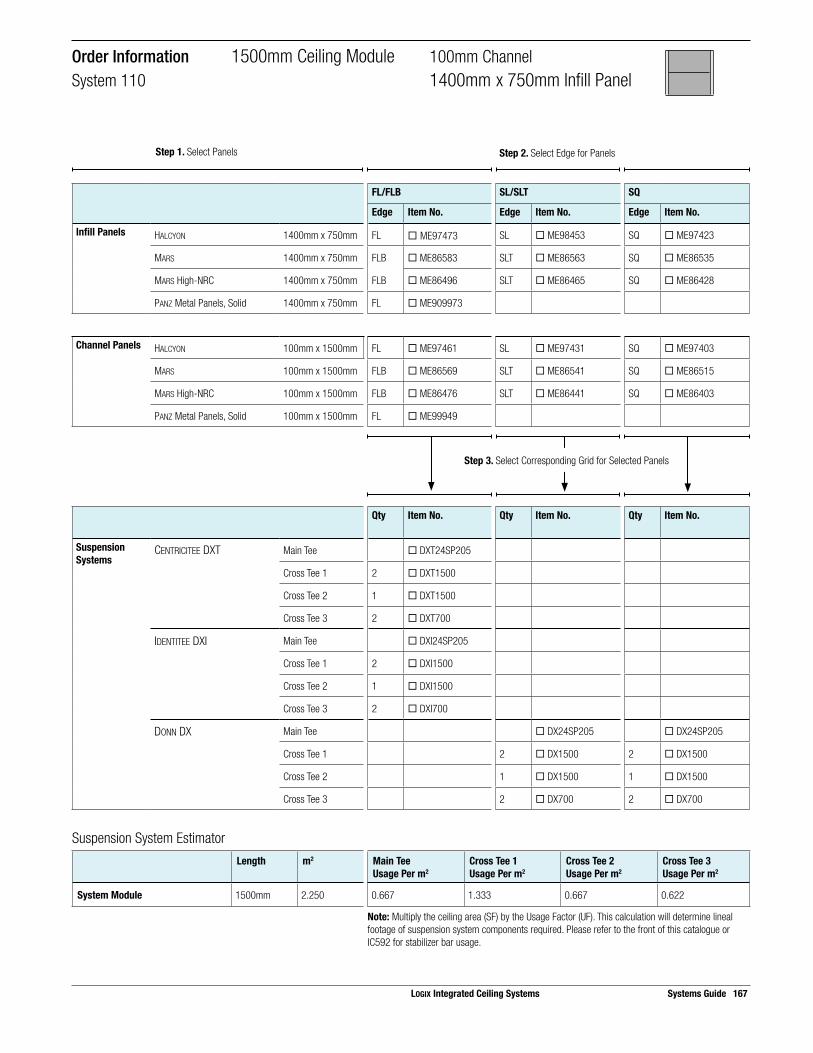
LOGIX Integrated Ceiling Systems Systems Guide 167
Order Information 1500mm Ceiling Module 100mm ChannelSystem 110 1400mm x 750mm Infill Panel
Step 1. Select Panels Step 2. Select Edge for Panels
Step 3. Select Corresponding Grid for Selected Panels
FL/FLB SL/SLT SQ
Edge Item No. Edge Item No. Edge Item No.
Infill Panels HALCYON 1400mm x 750mm FL ¨ ME97473 SL ¨ ME98453 SQ ¨ ME97423
MARS 1400mm x 750mm FLB ¨ ME86583 SLT ¨ ME86563 SQ ¨ ME86535
MARS High-NRC 1400mm x 750mm FLB ¨ ME86496 SLT ¨ ME86465 SQ ¨ ME86428
PANZ Metal Panels, Solid 1400mm x 750mm FL ¨ ME909973
Channel Panels HALCYON 100mm x 1500mm FL ¨ ME97461 SL ¨ ME97431 SQ ¨ ME97403
MARS 100mm x 1500mm FLB ¨ ME86569 SLT ¨ ME86541 SQ ¨ ME86515
MARS High-NRC 100mm x 1500mm FLB ¨ ME86476 SLT ¨ ME86441 SQ ¨ ME86403
PANZ Metal Panels, Solid 100mm x 1500mm FL ¨ ME99949
Qty Item No. Qty Item No. Qty Item No.
Suspension Systems
CENTRICITEE DXT Main Tee ¨ DXT24SP205
Cross Tee 1 2 ¨ DXT1500
Cross Tee 2 1 ¨ DXT1500
Cross Tee 3 2 ¨ DXT700
IDENTITEE DXI Main Tee ¨ DXI24SP205
Cross Tee 1 2 ¨ DXI1500
Cross Tee 2 1 ¨ DXI1500
Cross Tee 3 2 ¨ DXI700
DONN DX Main Tee ¨ DX24SP205 ¨ DX24SP205
Cross Tee 1 2 ¨ DX1500 2 ¨ DX1500
Cross Tee 2 1 ¨ DX1500 1 ¨ DX1500
Cross Tee 3 2 ¨ DX700 2 ¨ DX700
Suspension System EstimatorLength m2 Main Tee
Usage Per m2Cross Tee 1Usage Per m2
Cross Tee 2Usage Per m2
Cross Tee 3Usage Per m2
System Module 1500mm 2.250 0.667 1.333 0.667 0.622
Note: Multiply the ceiling area (SF) by the Usage Factor (UF). This calculation will determine lineal footage of suspension system components required. Please refer to the front of this catalogue or IC592 for stabilizer bar usage.
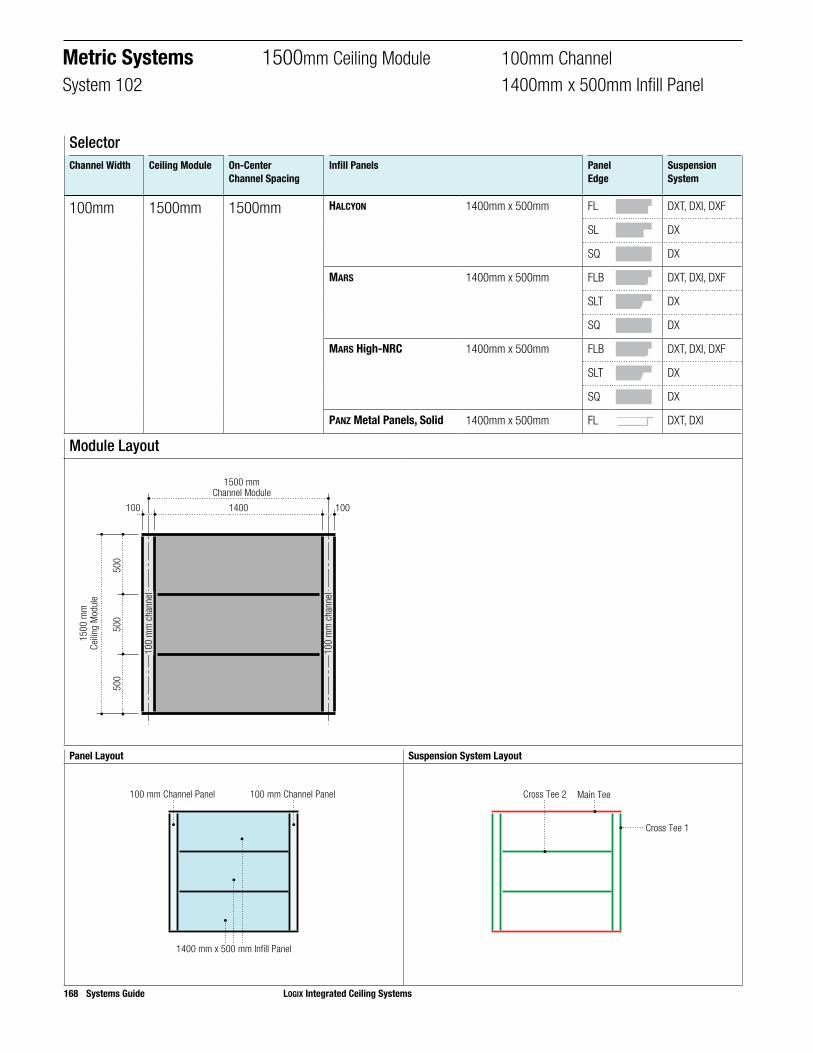
168 Systems Guide LOGIX Integrated Ceiling Systems
Panel Layout Suspension System Layout
1400 mm x 500 mm Infill Panel
100 mm Channel Panel 100 mm Channel Panel
Main Tee
Cross Tee 1
Cross Tee 2
Module Layout
1400
500
500
500
100 100
1500 mmChannel Module
1500
mm
Ceilin
g M
odul
e
100
mm
cha
nnel
100
mm
cha
nnel
SelectorChannel Width Ceiling Module On-Center
Channel SpacingInfill Panels Panel
EdgeSuspension System
100mm 1500mm 1500mm HALCYON 1400mm x 500mm FL DXT, DXI, DXF
SL DX
SQ DX
MARS 1400mm x 500mm FLB DXT, DXI, DXF
SLT DX
SQ DX
MARS High-NRC 1400mm x 500mm FLB DXT, DXI, DXF
SLT DX
SQ DX
PANZ Metal Panels, Solid 1400mm x 500mm FL DXT, DXI
Metric Systems 1500mm Ceiling Module 100mm ChannelSystem 102 1400mm x 500mm Infill Panel

LOGIX Integrated Ceiling Systems Systems Guide 169
Order Information 1500mm Ceiling Module 100mm ChannelSystem 102 1400mm x 500mm Infill Panel
1400
500
500
500
100 100
1500 mmChannel Module
1500
mm
Ceilin
g M
odul
e
100
mm
cha
nnel
100
mm
cha
nnel
Step 2. Select Edge for PanelsStep 1. Select Panels
Step 3. Select Corresponding Grid for Selected Panels
FL/FLB SL/SLT SQ
Edge Item No. Edge Item No. Edge Item No.
Infill Panels HALCYON 1400mm x 500mm FL ¨ ME97464 SL ¨ ME97437 SQ ¨ ME97408
MARS 1400mm x 500mm FLB ¨ ME86571 SLT ¨ ME86548 SQ ¨ ME86520
MARS High-NRC 1400mm x 500mm FLB ¨ ME86480 SLT ¨ ME86448 SQ ¨ ME86411
PANZ Metal Panels, Solid 300mm x 1800mm FL ¨ ME909956
Channel Panels HALCYON 100mm x 1500mm FL ¨ ME97461 SL ¨ ME97431 SQ ¨ ME97403
MARS 100mm x 1500mm FLB ¨ ME86569 SLT ¨ ME86541 SQ ¨ ME86515
MARS High-NRC 100mm x 1500mm FLB ¨ ME86476 SLT ¨ ME86441 SQ ¨ ME86403
PANZ Metal Panels, Solid 100mm x 1500mm FL ¨ ME909949
Qty Item No. Qty Item No. Qty Item No.
Suspension Systems
CENTRICITEE DXT Main Tee ¨ MEDXT24SP205
Cross Tee 1 2 ¨ MEDXT1000
IDENTITEE DXI Main Tee ¨ MEDXI24SP205
Cross Tee 1 2 ¨ MEDXI1000
DONN DX Main Tee ¨ MEDX24SP205 ¨ MEDX24SP205
Cross Tee 1 2 ¨ MEDX1000 2 ¨ MEDX1000
Suspension System EstimatorLength m2 Main Tee
Usage Per m2Cross Tee 1Usage Per m2
System Module 1500mm 1.500 1.000 1.333
Note: Multiply the ceiling area (SF) by the Usage Factor (UF). This calculation will determine lineal footage of suspension system components required. Please refer to the front of this catalogue or IC592 for stabilizer bar usage.

170 Systems Guide LOGIX Integrated Ceiling Systems
Panel Layout Suspension System Layout
1400 mm x 1500 mm Infill Panel
100 mm Channel Panel 100 mm Channel Panel
Main Tee
Cross Tee 1
Module Layout
1400100 100
1500 mmChannel Module
1500
mm
Ceilin
g M
odul
e
100
mm
cha
nnel
100
mm
cha
nnel
SelectorChannel Width Ceiling Module On-Center
Channel SpacingInfill Panels Panel
EdgeSuspension System
10mm 1500mm 1500mm HALCYON 1400mm x 1500mm FL DXT, DXI, DXF
SL DX
SQ DX
Metric Systems 1500mm Ceiling Module 100mm ChannelSystem 129 1400mm x 1500mm Infill Panel

Suspension System EstimatorLength m2 Main Tee
Usage Per m2Cross Tee 1Usage Per m2
Cross Tee 2Usage Per m2
System Module 1500mm 2.250 0.667 1.333 0.622
Note: Multiply the ceiling area (SF) by the Usage Factor (UF). This calculation will determine lineal footage of suspension system components required. Please refer to the front of this catalogue or IC592 for stabilizer bar usage.
Step 3. Select Corresponding Grid for Selected Panels
FL/FLB SL/SLT SQ
Edge Item No. Edge Item No. Edge Item No.
Infill Panels HALCYON 1400mm x 1500mm FL ¨ ME99229 SL ¨ ME97537 SQ ¨ ME97567
Channel Panels HALCYON 100mm x 1500mm FL ¨ ME97461 SL ¨ ME97431 SQ ¨ ME97403
PANZ Metal Panels, Solid 100mm x 1500mm FL ¨ ME909949
Qty Item No. Qty Item No. Qty Item No.
Suspension Systems
CENTRICITEE DXT Main Tee ¨ MEDXT24SP205
Cross Tee 1 2 ¨ MEDXT1500
Cross Tee 2 1 ¨ MEDXT1400
IDENTITEE DXI Main Tee ¨ MEDXI24SP205
Cross Tee 1 2 ¨ MEDXI1500
Cross Tee 2 1 ¨ MEDXI1400
DONN DX Main Tee ¨ MEDX24SP205 ¨ MEDX24SP205
Cross Tee 1 2 ¨ MEDX1500 2 ¨ MEDX1500
Cross Tee 2 1 ¨ MEDX1400 1 ¨ MEDX1400
Order Information 1500mm Ceiling Module 100mm Channel
System 129 1400mm x 1500mm Infill Panel
LOGIX Integrated Ceiling Systems Systems Guide 171
Step 1. Select Panels Step 2. Select Edge for Panels

172 Systems Guide LOGIX Integrated Ceiling Systems
Panel Layout Suspension System Layout
675 mm x 500 mm Infill Panel
150 mm Channel Panel 150 mm Channel Panel
Main Tee
Cross Tee 1
Cross Tee 3
Cross Tee 2
Module Layout
675150 150675
500
500
1500 mmChannel Module
1000
mm
Ceilin
g M
odul
e
150
mm
cha
nnel
150
mm
cha
nnel
SelectorChannel Width Ceiling Module On-Center
Channel SpacingInfill Panels Panel
EdgeSuspension System
150mm 1000mm 1500mm HALCYON 675mm x 500mm FL DXT, DXI, DXF
SL DX
SQ DX
MARS 675mm x 500mm FLB DXT, DXI, DXF
SLT DX
SQ DX
MARS High-NRC 675mm x 500mm FLB DXT, DXI, DXF
SLT DX
SQ DX
Metric Systems 1000mm Ceiling Module 150mm ChannelSystem 136 675mm x 500mm Infill Panel
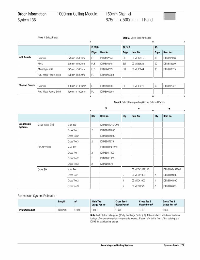
Suspension System EstimatorLength m2 Main Tee
Usage Per m2Cross Tee 1Usage Per m2
Cross Tee 2Usage Per m2
Cross Tee 3Usage Per m2
System Module 1500mm 1.500 1.000 1.333 0.667 0.900
Note: Multiply the ceiling area (SF) by the Usage Factor (UF). This calculation will determine lineal footage of suspension system components required. Please refer to the front of this catalogue or IC592 for stabilizer bar usage.
Step 3. Select Corresponding Grid for Selected Panels
FL/FLB SL/SLT SQ
Edge Item No. Edge Item No. Edge Item No.
Infill Panels HALCYON 675mm x 500mm FL ¨ ME97544 SL ¨ ME97515 SQ ¨ ME97486
MARS 675mm x 500mm FLB ¨ ME86648 SLT ¨ ME86625 SQ ¨ ME86599
MARS High-NRC 675mm x 500mm FLB ¨ ME86069 SLT ¨ ME86044 SQ ¨ ME86015
PANZ Metal Panels, Solid 675mm x 500mm FL ¨ ME909960
Channel Panels HALCYON 150mm x 1000mm FL ¨ ME98198 SL ¨ ME99271 SQ ¨ ME97227
PANZ Metal Panels, Solid 150mm x 1000mm FL ¨ ME909953
Qty Item No. Qty Item No. Qty Item No.
Suspension Systems
CENTRICITEE DXT Main Tee ¨ MEDXT24SP206
Cross Tee 1 2 ¨ MEDXT1000
Cross Tee 2 1 ¨ MEDXT1000
Cross Tee 3 2 ¨ MEDXT675
IDENTITEE DXI Main Tee ¨ MEDXI24SP206
Cross Tee 1 2 ¨ MEDXI1000
Cross Tee 2 1 ¨ MEDXI1000
Cross Tee 3 2 ¨ MEDXI675
DONN DX Main Tee ¨ MEDX24SP206 ¨ MEDX24SP206
Cross Tee 1 2 ¨ MEDX1000 2 ¨ MEDX1000
Cross Tee 2 1 ¨ MEDX1000 1 ¨ MEDX1000
Cross Tee 3 2 ¨ MEDXI675 2 ¨ MEDXI675
Order Information 1000mm Ceiling Module 150mm ChannelSystem 136 675mm x 500mm Infill Panel
LOGIX Integrated Ceiling Systems Systems Guide 173
Step 1. Select Panels Step 2. Select Edge for Panels

174 Systems Guide LOGIX Integrated Ceiling Systems
Panel Layout Suspension System Layout
1350 mm x 500 mm Infill Panel
150 mm Channel Panel 150 mm Channel Panel
Main Tee
Cross Tee 1
Cross Tee 2
Module Layout
1350150 150
500
500
1500 mmChannel Module
1000
mm
Ceilin
g M
odul
e
150
mm
cha
nnel
150
mm
cha
nnel
SelectorChannel Width Ceiling Module On-Center
Channel SpacingInfill Panels Panel
EdgeSuspension System
150mm 1000mm 1500mm HALCYON 1350mm x 500mm FL DXT, DXI, DXF
SL DX
SQ DX
MARS 1350mm x 500mm FLB DXT, DXI, DXF
SLT DX
SQ DX
MARS High-NRC 1350mm x 500mm FLB DXT, DXI, DXF
SLT DX
SQ DX
Metric Systems 1000mm Ceiling Module 150mm ChannelSystem 122 1350mm x 500mm Infill Panel
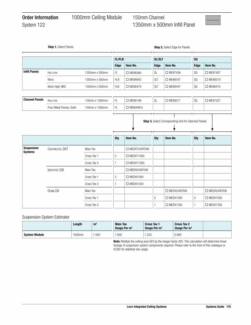
Suspension System EstimatorLength m2 Main Tee
Usage Per m2Cross Tee 1Usage Per m2
Cross Tee 2Usage Per m2
System Module 1500mm 1.500 1.000 1.333 0.900
Note: Multiply the ceiling area (SF) by the Usage Factor (UF). This calculation will determine lineal footage of suspension system components required. Please refer to the front of this catalogue or IC592 for stabilizer bar usage.
Step 3. Select Corresponding Grid for Selected Panels
Order Information 1000mm Ceiling Module 150mm ChannelSystem 122 1350mm x 500mm Infill Panel
FL/FLB SL/SLT SQ
Edge Item No. Edge Item No. Edge Item No.
Infill Panels HALCYON 1350mm x 500mm FL ¨ ME98360 SL ¨ ME97436 SQ ¨ ME97407
MARS 1350mm x 500mm FLB ¨ ME88845 SLT ¨ ME86547 SQ ¨ ME86519
MARS High-NRC 1350mm x 500mm FLB ¨ ME86479 SLT ¨ ME86447 SQ ¨ ME86410
Channel Panels HALCYON 150mm x 1000mm FL ¨ ME98198 SL ¨ ME99271 SQ ¨ ME97227
PANZ Metal Panels, Solid 150mm x 1000mm FL ¨ ME909953
Qty Item No. Qty Item No. Qty Item No.
Suspension Systems
CENTRICITEE DXT Main Tee ¨ MEDXT24SP206
Cross Tee 1 2 ¨ MEDXT1000
Cross Tee 2 1 ¨ MEDXT1350
IDENTITEE DXI Main Tee ¨ MEDXI24SP206
Cross Tee 1 2 ¨ MEDXI1000
Cross Tee 2 1 ¨ MEDXI1350
DONN DX Main Tee ¨ MEDX24SP206 ¨ MEDX24SP206
Cross Tee 1 2 ¨ MEDX1000 2 ¨ MEDX1000
Cross Tee 2 1 ¨ MEDX1350 1 ¨ MEDX1350
LOGIX Integrated Ceiling Systems Systems Guide 175
Step 1. Select Panels Step 2. Select Edge for Panels

176 Systems Guide LOGIX Integrated Ceiling Systems
Panel Layout Suspension System Layout
1350 mm x 1000 mm Infill Panel
150 mm Channel Panel 150 mm Channel Panel
Main Tee
Cross Tee 1
Module Layout
1350150 150
1500 mmChannel Module
1000
mm
Ceilin
g M
odul
e
150
mm
cha
nnel
150
mm
cha
nnel
SelectorChannel Width Ceiling Module On-Center
Channel SpacingInfill Panels Panel
EdgeSuspension System
150mm 1000mm 1500mm HALCYON 1350mm x 1000mm FL DXT, DXI, DXF
SL DX
SQ DX
Metric Systems 1000mm Ceiling Module 150mm ChannelSystem 107 1350mm x 1000mm Infill Panel

Suspension System EstimatorLength m2 Main Tee
Usage Per m2Cross Tee 1Usage Per m2
System Module 1500mm 1.500 1.000 1.333
Note: Multiply the ceiling area (SF) by the Usage Factor (UF). This calculation will determine lineal footage of suspension system components required. Please refer to the front of this catalogue or IC592 for stabilizer bar usage.
Step 3. Select Corresponding Grid for Selected Panels
FL/FLB SL/SLT SQ
Edge Item No. Edge Item No. Edge Item No.
Infill Panels HALCYON 1350mm x 1000mm FL ¨ ME97558 SL ¨ ME97529 SQ ¨ ME97501
Channel Panels HALCYON 150mm x 1000mm FL ¨ ME97541 SL ¨ ME97512 SQ ¨ ME97483
PANZ Metal Panels, Solid 150mm x 1000mm FL ¨ ME909953
Qty Item No. Qty Item No. Qty Item No.
Suspension Systems
CENTRICITEE DXT Main Tee ¨ MEDXT24SP206
Cross Tee 1 2 ¨ MEDXT1000
IDENTITEE DXI Main Tee ¨ MEDXI24SP206
Cross Tee 1 2 ¨ MEDXI1000
DONN DX Main Tee ¨ MEDX24SP206 ¨ MEDX24SP206
Cross Tee 1 2 ¨ MEDX1000 2 ¨ MEDX1000
Order Information 1000mm Ceiling Module 150mm ChannelSystem 107 1350mm x 1000mm Infill Panel
LOGIX Integrated Ceiling Systems Systems Guide 177
Step 1. Select Panels Step 2. Select Edge for Panels

178 Systems Guide LOGIX Integrated Ceiling Systems
Panel Layout Suspension System Layout
525 mm x 600 mm Infill Panel
150 mm Channel Panel 150 mm Channel Panel
Cross Tee 3 Main Tee
Cross Tee 1
Cross Tee 2
Module Layout
150 150
600
600
525 525
1200 mmChannel Module
1200
mm
Ceilin
g M
odul
e
150
mm
cha
nnel
150
mm
cha
nnel
SelectorChannel Width Ceiling Module On-Center
Channel SpacingInfill Panels Panel
EdgeSuspension System
150mm 1200mm 1200mm HALCYON 525mm x 600mm FL DXT, DXI, DXF
SL DX
SQ DX, DXT
MARS 525mm x 600mm FLB DXT, DXI, DXF
SLT DX
SQ DX, DXT
MARS High-NRC 525mm x 600mm FLB DXT, DXI, DXF
SLT DX
SQ DX, DXT
Metric Systems 1200mm Ceiling Module 150mm ChannelSystem 113 525mm x 600mm Infill Panel

Suspension System EstimatorLength m2 Main Tee
Usage Per m2Cross Tee 1Usage Per m2
Cross Tee 2Usage Per m2
Cross Tee 3Usage Per m2
System Module 1200mm 1.440 0.833 1.667 0.833 0.729
Note: Multiply the ceiling area (SF) by the Usage Factor (UF). This calculation will determine lineal footage of suspension system components required. Please refer to the front of this catalogue or IC592 for stabilizer bar usage.
Step 3. Select Corresponding Grid for Selected Panels
FL/FLB SL/SLT SQ
Edge Item No. Edge Item No. Edge Item No.
Infill Panels HALCYON 525mm x 600mm FL ¨ ME98195 SL ¨ ME98220 SQ ¨ ME97411
MARS 525mm x 600mm FLB ¨ ME88840 SLT ¨ ME86550 SQ ¨ ME86522
MARS High-NRC 525mm x 600mm FLB ¨ ME86483 SLT ¨ ME86451 SQ ¨ ME86414
Channel Panels HALCYON 150mm x 1200mm FL ¨ ME97572 SL ¨ ME97493 SQ ¨ ME97479
MARS 150mm x 1200mm FLB ¨ ME88887 SLT ¨ ME86542 SQ ¨ ME86325
MARS High-NRC 150mm x 1200mm FLB ¨ ME86331 SLT ¨ ME86442 SQ ¨ ME86404
PANZ Metal Panels, Solid 150mm x 1200mm FL ¨ ME909954
Qty Item No. Qty Item No. Qty Item No.
Suspension Systems
CENTRICITEE DXT Main Tee ¨ MEDXT24SP204 ¨ MEDXT24SP204
Cross Tee 1 2 ¨ MEDXT1200 2 ¨ MEDXT1200
Cross Tee 2 1 ¨ MEDXT1200 1 ¨ MEDXT1200
Cross Tee 3 2 ¨ MEDXT525 2 ¨ MEDXT525
IDENTITEE DXI Main Tee ¨ MEDXI24SP204
Cross Tee 1 2 ¨ MEDXI1200
Cross Tee 2 1 ¨ MEDXI1200
Cross Tee 3 2 ¨ MEDXI525
DONN DX Main Tee ¨ MEDX24SP204 ¨ MEDX24SP204
Cross Tee 1 2 ¨ MEDX1200 2 ¨ MEDX1200
Cross Tee 2 1 ¨ MEDX1200 1 ¨ MEDX1200
Cross Tee 3 2 ¨ MEDX525 2 ¨ MEDX525
Order Information 1200mm Ceiling Module 150mm ChannelSystem 113 525mm x 600mm Infill Panel
LOGIX Integrated Ceiling Systems Systems Guide 179
Step 1. Select Panels Step 2. Select Edge for Panels

180 Systems Guide LOGIX Integrated Ceiling Systems
Panel Layout Suspension System Layout
1050 mm x 600 mm Infill Panel
150 mm Channel Panel 150 mm Channel Panel
Cross Tee 2 Main Tee
Cross Tee 1
Module Layout
150 150
600
600
1050
1200 mmChannel Module
1200
mm
Ceilin
g M
odul
e
150
mm
cha
nnel
150
mm
cha
nnel
SelectorChannel Width Ceiling Module On-Center
Channel SpacingInfill Panels Panel
EdgeSuspension System
150mm 1200mm 1200mm HALCYON 1050mm x 600mm FL DXT, DXI, DXF
SL DX
SQ DX
Metric Systems 1200mm Ceiling Module 150mm ChannelSystem 109 1050mm x 600mm Infill Panel

Suspension System EstimatorLength m2 Main Tee
Usage Per m2Cross Tee 1Usage Per m2
Cross Tee 2Usage Per m2
System Module 1200mm 1.440 0.833 1.667 0.729
Note: Multiply the ceiling area (SF) by the Usage Factor (UF). This calculation will determine lineal footage of suspension system components required. Please refer to the front of this catalogue or IC592 for stabilizer bar usage.
Step 3. Select Corresponding Grid for Selected Panels
FL/FLB SL/SLT SQ
Edge Item No. Edge Item No. Edge Item No.
Infill Panels HALCYON 1050mm x 600mm FL ¨ ME97560 SL ¨ ME97531 SQ ¨ ME97503
Channel Panels HALCYON 150mm x 1200mm FL ¨ ME97572 SL ¨ ME97493 SQ ¨ ME97479
PANZ Metal Panels, Solid 150mm x 1200mm FL ¨ ME909954
Qty Item No. Qty Item No. Qty Item No.
Suspension Systems
CENTRICITEE DXT Main Tee ¨ MEDXT24SP204
Cross Tee 1 2 ¨ MEDXT1200
Cross Tee 2 1 ¨ MEDXT1050
IDENTITEE DXI Main Tee ¨ MEDXI24SP204
Cross Tee 1 2 ¨ MEDXI1200
Cross Tee 2 1 ¨ MEDXI1050
DONN DX Main Tee ¨ MEDX24SP204 ¨ MEDX24SP204
Cross Tee 1 2 ¨ MEDX1200 2 ¨ MEDX1200
Cross Tee 2 1 ¨ MEDX1050 1 ¨ MEDX1050
Order Information 1200mm Ceiling Module 150mm ChannelSystem 109 1050mm x 600mm Infill Panel
LOGIX Integrated Ceiling Systems Systems Guide 181
Step 1. Select Panels Step 2. Select Edge for Panels

182 Systems Guide LOGIX Integrated Ceiling Systems
Panel Layout Suspension System Layout
1050 mm x 1200 mm Infill Panel
150 mm Channel Panel 150 mm Channel Panel
Main Tee
Cross Tee 1
Module Layout
150 1501050
1200 mmChannel Module
1200
mm
Ceilin
g M
odul
e
150
mm
cha
nnel
150
mm
cha
nnel
SelectorChannel Width Ceiling Module On-Center
Channel SpacingInfill Panels Panel
EdgeSuspension System
150mm 1200mm 1200mm HALCYON 1050mm x 1200mm FL DXT, DXI, DXF
SL DX
SQ DX
Metric Systems 1200 mm Ceiling Module 150mm ChannelSystem 101 1050mm x 1200mm Infill Panel
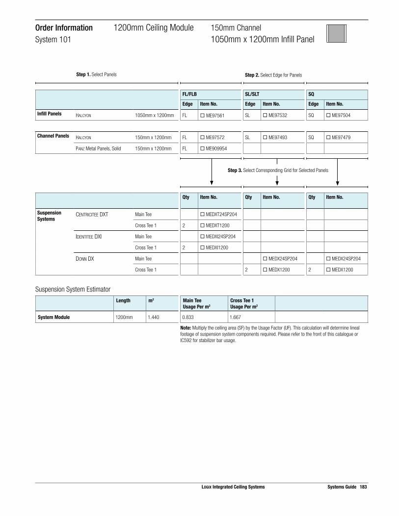
Suspension System EstimatorLength m2 Main Tee
Usage Per m2Cross Tee 1Usage Per m2
System Module 1200mm 1.440 0.833 1.667
Note: Multiply the ceiling area (SF) by the Usage Factor (UF). This calculation will determine lineal footage of suspension system components required. Please refer to the front of this catalogue or IC592 for stabilizer bar usage.
Step 3. Select Corresponding Grid for Selected Panels
Order Information 1200mm Ceiling Module 150mm ChannelSystem 101 1050mm x 1200mm Infill Panel
FL/FLB SL/SLT SQ
Edge Item No. Edge Item No. Edge Item No.
Infill Panels HALCYON 1050mm x 1200mm FL ¨ ME97561 SL ¨ ME97532 SQ ¨ ME97504
Channel Panels HALCYON 150mm x 1200mm FL ¨ ME97572 SL ¨ ME97493 SQ ¨ ME97479
PANZ Metal Panels, Solid 150mm x 1200mm FL ¨ ME909954
Qty Item No. Qty Item No. Qty Item No.
Suspension Systems
CENTRICITEE DXT Main Tee ¨ MEDXT24SP204
Cross Tee 1 2 ¨ MEDXT1200
IDENTITEE DXI Main Tee ¨ MEDXI24SP204
Cross Tee 1 2 ¨ MEDXI1200
DONN DX Main Tee ¨ MEDX24SP204 ¨ MEDX24SP204
Cross Tee 1 2 ¨ MEDX1200 2 ¨ MEDX1200
LOGIX Integrated Ceiling Systems Systems Guide 183
Step 1. Select Panels Step 2. Select Edge for Panels

184 Systems Guide LOGIX Integrated Ceiling Systems
Panel Layout Suspension System Layout
600 mm x 600 mm Infill Panel
150 mm Channel Panel 150 mm Channel Panel
`
Main Tee
Cross Tee 1
Cross Tee 3
Cross Tee 2
Module Layout
600
600
600 600150 150
1350 mmChannel Module
1200
mm
Ceilin
g M
odul
e
150
mm
cha
nnel
150
mm
cha
nnel
SelectorChannel Width Ceiling Module On-Center
Channel SpacingInfill Panels Panel
EdgeSuspension System
150mm 1200mm 1350mm HALCYON 600mm x 600mm FL DXT, DXI, DXF
SL DX
SQ DX, DXT
MARS 600mm x 600mm FLB DXT, DXI, DXF
SLT DX
SQ DX, DXT
MARS High-NRC 600mm x 600mm FLB DXT, DXI, DXF
SLT DX
SQ DX, DXT
PANZ Metal Panels, Solid 600mm x 600mm FL DXT, DXI
Metric Systems 1200mm Ceiling Module 150mm ChannelSystem 127 600mm x 600mm Infill Panel

Suspension System EstimatorLength m2 Main Tee
Usage Per m2Cross Tee 1Usage Per m2
Cross Tee 2Usage Per m2
Cross Tee 3Usage Per m2
System Module 1350mm 1.620 0.833 1.481 0.741 0.741
Note: Multiply the ceiling area (SF) by the Usage Factor (UF). This calculation will determine lineal footage of suspension system components required. Please refer to the front of this catalogue or IC592 for stabilizer bar usage.
Step 3. Select Corresponding Grid for Selected Panels
FL/FLB SL/SLT SQ
Edge Item No. Edge Item No. Edge Item No.
Infill Panels HALCYON 600mm x 600mm FL ¨ ME98225 SL ¨ ME98223 SQ ¨ ME98221
MARS 600mm x 600mm FLB ¨ ME86985 SLT ¨ ME86785 SQ ¨ ME86185
MARS High-NRC 600mm x 600mm FLB ¨ ME87100 SLT ¨ ME87200 SQ ¨ ME86100
PANZ Metal Panels, Solid 600mm x 600mm FL ¨ ME909975
Channel Panels HALCYON 150mm x 1200mm FL ¨ ME97572 SL ¨ ME97493 SQ ¨ ME97479
MARS 150mm x 1200mm FLB ¨ ME88887 SLT ¨ ME86542 SQ ¨ ME86325
MARS High-NRC 150mm x 1200mm FLB ¨ ME86331 SLT ¨ ME86442 SQ ¨ ME86404
PANZ Metal Panels, Solid 150mm x 1200mm FL ¨ ME909954
Qty Item No. Qty Item No. Qty Item No.
Suspension Systems
CENTRICITEE DXT Main Tee ¨ MEDXT3600 ¨ MEDXT3600
Cross Tee 1 2 ¨ MEDXT1200 2 ¨ MEDXT1200
Cross Tee 2 1 ¨ MEDXT1200 1 ¨ MEDXT1200
Cross Tee 3 2 ¨ MEDXT600 2 ¨ MEDXT600
IDENTITEE DXI Main Tee ¨ MEDXI3600
Cross Tee 1 2 ¨ MEDXI1200
Cross Tee 2 1 ¨ MEDXI1200
Cross Tee 3 2 ¨ MEDXI600
DONN DX Main Tee ¨ MEDX3600 ¨ MEDX3600
Cross Tee 1 2 ¨ MEDX1200 2 ¨ MEDX1200
Cross Tee 2 1 ¨ MEDX1200 1 ¨ MEDX1200
Cross Tee 3 2 ¨ MEDX600 2 ¨ MEDX600
Order Information 1200mm Ceiling Module 150mm ChannelSystem 127 600mm x 600mm Infill Panel
LOGIX Integrated Ceiling Systems Systems Guide 185
Step 1. Select Panels Step 2. Select Edge for Panels
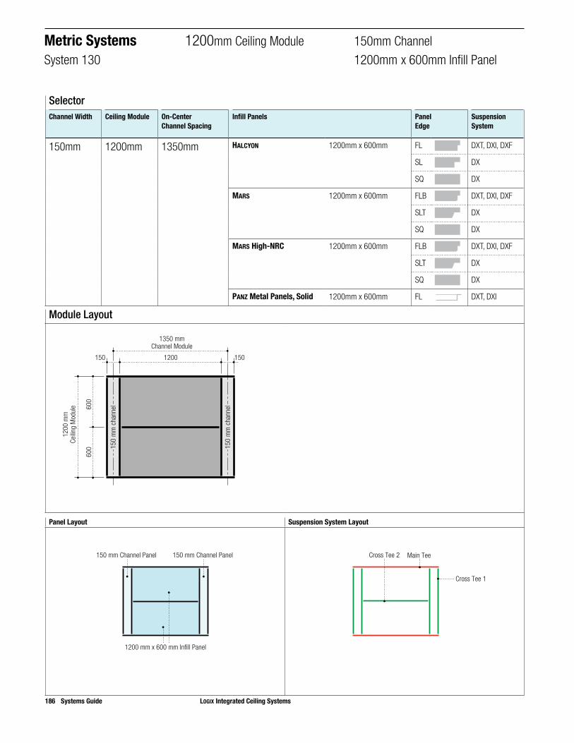
186 Systems Guide LOGIX Integrated Ceiling Systems
Panel Layout Suspension System Layout
1200 mm x 600 mm Infill Panel
150 mm Channel Panel 150 mm Channel Panel
Main Tee
Cross Tee 1
Cross Tee 2
Module Layout
600
600
1200150 150
1350 mmChannel Module
1200
mm
Ceilin
g M
odul
e
150
mm
cha
nnel
150
mm
cha
nnel
SelectorChannel Width Ceiling Module On-Center
Channel SpacingInfill Panels Panel
EdgeSuspension System
150mm 1200mm 1350mm HALCYON 1200mm x 600mm FL DXT, DXI, DXF
SL DX
SQ DX
MARS 1200mm x 600mm FLB DXT, DXI, DXF
SLT DX
SQ DX
MARS High-NRC 1200mm x 600mm FLB DXT, DXI, DXF
SLT DX
SQ DX
PANZ Metal Panels, Solid 1200mm x 600mm FL DXT, DXI
Metric Systems 1200mm Ceiling Module 150mm ChannelSystem 130 1200mm x 600mm Infill Panel

Suspension System EstimatorLength m2 Main Tee
Usage Per m2Cross Tee 1Usage Per m2
Cross Tee 2Usage Per m2
System Module 1350mm 1.620 0.833 1.481 0.741
Note: Multiply the ceiling area (SF) by the Usage Factor (UF). This calculation will determine lineal footage of suspension system components required. Please refer to the front of this catalogue or IC592 for stabilizer bar usage.
Step 3. Select Corresponding Grid for Selected Panels
FL/FLB SL/SLT SQ
Edge Item No. Edge Item No. Edge Item No.
Infill Panels HALCYON 1200mm x 600mm FL ¨ ME98245 SL ¨ ME98243 SQ ¨ ME98241
MARS 1200mm x 600mm FLB ¨ ME88985 SLT ¨ ME88785 SQ ¨ ME88185
MARS High-NRC 1200mm x 600mm FLB ¨ ME89500 SLT ¨ ME89600 SQ ¨ ME86300
PANZ Metal Panels, Solid 1200mm x 600mm FL ¨ ME909974
Channel Panels HALCYON 150mm x 1200mm FL ¨ ME97572 SL ¨ ME97493 SQ ¨ ME97479
MARS 150mm x 1200mm FLB ¨ ME88887 SLT ¨ ME86542 SQ ¨ ME86325
MARS High-NRC 150mm x 1200mm FLB ¨ ME86331 SLT ¨ ME86442 SQ ¨ ME86404
PANZ Metal Panels, Solid 150mm x 1200mm FL ¨ ME909954
Qty Item No. Qty Item No. Qty Item No.
Suspension Systems
CENTRICITEE DXT(Use with PANZ)
Main Tee ¨ MEDXT3600
Cross Tee 1 2 ¨ MEDXT1200
Cross Tee 2 1 ¨ MEDXT1200
IDENTITEE DXI Main Tee ¨ MEDXI3600
Cross Tee 1 2 ¨ MEDXI1200
Cross Tee 2 1 ¨ MEDXI1200
DONN DX Main Tee ¨ MEDX3600 ¨ MEDX3600
Cross Tee 1 2 ¨ MEDX1200 2 ¨ MEDX1200
Cross Tee 2 1 ¨ MEDX1200 1 ¨ MEDX1200
Order Information 1200mm Ceiling Module 150mm ChannelSystem 130 1200mm x 600mm Infill Panel
LOGIX Integrated Ceiling Systems Systems Guide 187
Step 1. Select Panels Step 2. Select Edge for Panels

188 Systems Guide LOGIX Integrated Ceiling Systems
Panel Layout Suspension System Layout
1200 mm x 1200 mm Infill Panel
150 mm Channel Panel 150 mm Channel Panel
Main Tee
Cross Tee 1
Module Layout
1200150 150
1350 mmChannel Module
1200
mm
Ceilin
g M
odul
e
150
mm
cha
nnel
150
mm
cha
nnel
SelectorChannel Width Ceiling Module On-Center
Channel SpacingInfill Panels Panel
EdgeSuspension System
150mm 1200mm 1350mm HALCYON 1200mm x 1200mm FL DXT, DXI, DXF
SL DX
SQ DX
Metric Systems 1200mm Ceiling Module 150mm ChannelSystem 106 1200mm x 1200mm Infill Panel

Suspension System EstimatorLength m2 Main Tee
Usage Per m2Cross Tee 1Usage Per m2
System Module 1350mm 1.620 0.833 1.481
Note: Multiply the ceiling area (SF) by the Usage Factor (UF). This calculation will determine lineal footage of suspension system components required. Please refer to the front of this catalogue or IC592 for stabilizer bar usage.
Step 3. Select Corresponding Grid for Selected Panels
Order Information 1200mm Ceiling Module 150mm ChannelSystem 106 1200mm x 1200mm Infill Panel
FL/FLB SL/SLT SQ
Edge Item No. Edge Item No. Edge Item No.
Infill Panels HALCYON 1200mm x 1200mm FL ¨ ME98445 SL ¨ ME98443 SQ ¨ ME98441
Channel Panels HALCYON 150mm x 1200mm FL ¨ ME97572 SL ¨ ME97493 SQ ¨ ME97479
PANZ Metal Panels, Solid 150mm x 1200mm FL ¨ ME909954
Qty Item No. Qty Item No. Qty Item No.
Suspension Systems
CENTRICITEE DXT Main Tee ¨ MEDXT3600
Cross Tee 1 2 ¨ MEDXT1200
IDENTITEE DXI Main Tee ¨ MEDXI3600
Cross Tee 1 2 ¨ MEDXI1200
DONN DX Main Tee ¨ MEDX3600 ¨ MEDX3600
Cross Tee 1 2 ¨ MEDX1200 2 ¨ MEDX1200
LOGIX Integrated Ceiling Systems Systems Guide 189
Step 1. Select Panels Step 2. Select Edge for Panels

190 Systems Guide LOGIX Integrated Ceiling Systems
Panel Layout Suspension System Layout
1800 mm x 300 mm Infill Panel
150 mm Channel Panel 150 mm Channel Panel
Main Tee
Cross Tee 1
Cross Tee 2
Module Layout
300
300
300
300
1800150 150
1950 mmChannel Module
1200
mm
Ceilin
g M
odul
e
150
mm
cha
nnel
150
mm
cha
nnel
SelectorChannel Width Ceiling Module On-Center
Channel SpacingInfill Panels Panel
EdgeSuspension System
150mm 1200mm 1950mm HALCYON 1800mm x 300mm FL DXT, DXI, DXF
SL DX
SQ DX
MARS 1800mm x 300mm FLB DXT, DXI, DXF
SLT DX
SQ DX
MARS High-NRC 1800mm x 300mm FLB DXT, DXI, DXF
SLT DX
SQ DX
PANZ Metal Panels, Solid 1800mm x 300mm FL DXT, DXI
Metric Systems 1200mm Ceiling Module 150mm ChannelSystem 120 1800mm x 300mm Infill Panel
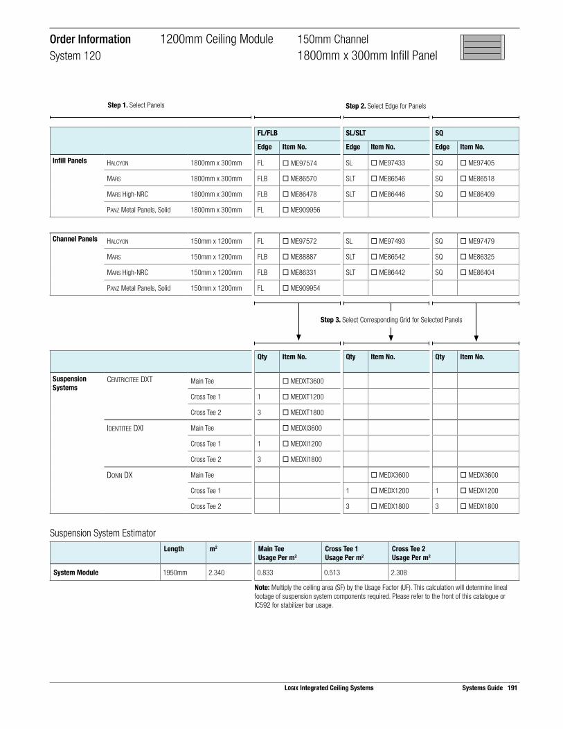
Suspension System EstimatorLength m2 Main Tee
Usage Per m2Cross Tee 1Usage Per m2
Cross Tee 2Usage Per m2
System Module 1950mm 2.340 0.833 0.513 2.308
Note: Multiply the ceiling area (SF) by the Usage Factor (UF). This calculation will determine lineal footage of suspension system components required. Please refer to the front of this catalogue or IC592 for stabilizer bar usage.
Step 3. Select Corresponding Grid for Selected Panels
FL/FLB SL/SLT SQ
Edge Item No. Edge Item No. Edge Item No.
Infill Panels HALCYON 1800mm x 300mm FL ¨ ME97574 SL ¨ ME97433 SQ ¨ ME97405
MARS 1800mm x 300mm FLB ¨ ME86570 SLT ¨ ME86546 SQ ¨ ME86518
MARS High-NRC 1800mm x 300mm FLB ¨ ME86478 SLT ¨ ME86446 SQ ¨ ME86409
PANZ Metal Panels, Solid 1800mm x 300mm FL ¨ ME909956
Channel Panels HALCYON 150mm x 1200mm FL ¨ ME97572 SL ¨ ME97493 SQ ¨ ME97479
MARS 150mm x 1200mm FLB ¨ ME88887 SLT ¨ ME86542 SQ ¨ ME86325
MARS High-NRC 150mm x 1200mm FLB ¨ ME86331 SLT ¨ ME86442 SQ ¨ ME86404
PANZ Metal Panels, Solid 150mm x 1200mm FL ¨ ME909954
Qty Item No. Qty Item No. Qty Item No.
Suspension Systems
CENTRICITEE DXT Main Tee ¨ MEDXT3600
Cross Tee 1 1 ¨ MEDXT1200
Cross Tee 2 3 ¨ MEDXT1800
IDENTITEE DXI Main Tee ¨ MEDXI3600
Cross Tee 1 1 ¨ MEDXI1200
Cross Tee 2 3 ¨ MEDXI1800
DONN DX Main Tee ¨ MEDX3600 ¨ MEDX3600
Cross Tee 1 1 ¨ MEDX1200 1 ¨ MEDX1200
Cross Tee 2 3 ¨ MEDX1800 3 ¨ MEDX1800
Order Information 1200mm Ceiling Module 150mm ChannelSystem 120 1800mm x 300mm Infill Panel
LOGIX Integrated Ceiling Systems Systems Guide 191
Step 1. Select Panels Step 2. Select Edge for Panels

192 Systems Guide LOGIX Integrated Ceiling Systems
Panel Layout Suspension System Layout
1800 mm x 600 mm Infill Panel
150 mm Channel Panel 150 mm Channel Panel
Main Tee
Cross Tee 1
Cross Tee 2
Module Layout
600
600
1800150 150
1950 mmChannel Module
1200
mm
Ceilin
g M
odul
e
150
mm
cha
nnel
150
mm
cha
nnel
SelectorChannel Width Ceiling Module On-Center
Channel SpacingInfill Panels Panel
EdgeSuspension System
150mm 1200mm 1950mm HALCYON 1800mm x 600mm FL DXT, DXI, DXF
SL DX
SQ DX
MARS 1800mm x 600mm FLB DXT, DXI, DXF
SLT DX
SQ DX
MARS High-NRC 1800mm x 600mm FLB DXT, DXI, DXF
SLT DX
SQ DX
PANZ Metal Panels, Solid 1800mm x 600mm FL DXT, DXI
Metric Systems 1200mm Ceiling Module 150mm ChannelSystem 137 1800mm x 600mm Infill Panel

Suspension System EstimatorLength m2 Main Tee
Usage Per m2Cross Tee 1Usage Per m2
Cross Tee 2Usage Per m2
System Module 1950mm 2.340 0.833 1.026 1.538
Note: Multiply the ceiling area (SF) by the Usage Factor (UF). This calculation will determine lineal footage of suspension system components required. Please refer to the front of this catalogue or IC592 for stabilizer bar usage.
Order Information 1200mm Ceiling Module 150mm ChannelSystem 137 1800mm x 600mm Infill Panel
Step 3. Select Corresponding Grid for Selected Panels
FL/FLB SL/SLT SQ
Edge Item No. Edge Item No. Edge Item No.
Infill Panels HALCYON 1800mm x 600mm FL ¨ ME97553 SL ¨ ME97445 SQ ¨ ME99234
MARS 1800mm x 600mm FLB ¨ ME88996 SLT ¨ ME86166 SQ ¨ ME86223
MARS High-NRC 1800mm x 600mm FLB ¨ ME89670 SLT ¨ ME89660 SQ ¨ ME86360
PANZ Metal Panels, Solid 1800mm x 600mm FL ¨ ME909970
Channel Panels HALCYON 150mm x 1200mm FL ¨ ME97572 SL ¨ ME97493 SQ ¨ ME97479
MARS 150mm x 1200mm FLB ¨ ME88887 SLT ¨ ME86542 SQ ¨ ME86325
MARS High-NRC 150mm x 1200mm FLB ¨ ME86331 SLT ¨ ME86442 SQ ¨ ME86404
PANZ Metal Panels, Solid 150mm x 1200mm FL ¨ ME90954
Qty Item No. Qty Item No. Qty Item No.
Suspension Systems
CENTRICITEE DXT Main Tee ¨ MEDXT3600
Cross Tee 1 2 ¨ MEDXT1200
Cross Tee 2 2 ¨ MEDXT1800
IDENTITEE DXI Main Tee ¨ MEDXI3600
Cross Tee 1 2 ¨ MEDXI1200
Cross Tee 2 2 ¨ MEDXI1800
DONN DX Main Tee ¨ MEDX3600 ¨ MEDX3600
Cross Tee 1 2 ¨ MEDX1200 2 ¨ MEDX1200
Cross Tee 2 2 ¨ MEDX1800 2 ¨ MEDX1800
LOGIX Integrated Ceiling Systems Systems Guide 193
Step 1. Select Panels Step 2. Select Edge for Panels

194 Systems Guide LOGIX Integrated Ceiling Systems
Panel Layout Suspension System Layout
1350 mm x 500 mm Infill Panel
150 mm Channel Panel 150 mm Channel Panel
Main Tee
Cross Tee 1
Cross Tee 2
Module Layout
500
500
500
1350150 150
1500 mmChannel Module
1500
mm
Ceilin
g M
odul
e
150
mm
cha
nnel
150
mm
cha
nnel
SelectorChannel Width Ceiling Module On-Center
Channel SpacingInfill Panels Panel
EdgeSuspension System
150mm 1500mm 1500mm HALCYON 1350mm x 500mm FL DXT, DXI, DXF
SL DX
SQ DX
MARS 1350mm x 500mm FLB DXT, DXI, DXF
SLT DX
SQ DX
MARS High-NRC 1350mm x 500mm FLB DXT, DXI, DXF
SLT DX
SQ DX
Metric Systems 1500mm Ceiling Module 150mm ChannelSystem 114 1350mm x 500mm Infill Panel

Suspension System EstimatorLength m2 Main Tee
Usage Per m2Cross Tee 1Usage Per m2
Cross Tee 2Usage Per m2
System Module 1500mm 1.500 1.000 2.000 1.800
Note: Multiply the ceiling area (SF) by the Usage Factor (UF). This calculation will determine lineal footage of suspension system components required. Please refer to the front of this catalogue or IC592 for stabilizer bar usage.
Step 3. Select Corresponding Grid for Selected Panels
FL/FLB SL/SLT SQ
Edge Item No. Edge Item No. Edge Item No.
Infill Panels HALCYON 1350mm x 500mm FL ¨ ME98360 SL ¨ ME97436 SQ ¨ ME97407
MARS 1350mm x 500mm FLB ¨ ME88845 SLT ¨ ME86547 SQ ¨ ME86519
MARS High-NRC 1350mm x 500mm FLB ¨ ME86479 SLT ¨ ME86447 SQ ¨ ME86410
PANZ Metal Panels, Solid 1350mm x 500mm FL ¨ ME909963
Channel Panels HALCYON 150mm x 1500mm FL ¨ ME97573 SL ¨ ME97570 SQ ¨ ME97490
MARS 150mm x 1500mm FLB ¨ ME86835 SLT ¨ ME86543 SQ ¨ ME86507
MARS High-NRC 150mm x 1500mm FLB ¨ ME86333 SLT ¨ ME86443 SQ ¨ ME86145
Qty Item No. Qty Item No. Qty Item No.
Suspension Systems
CENTRICITEE DXT Main Tee ¨ MEDXT24SP206
Cross Tee 1 2 ¨ MEDXT1500
Cross Tee 2 2 ¨ MEDXT1350
IDENTITEE DXI Main Tee ¨ MEDXI24SP206
Cross Tee 1 2 ¨ MEDXI1500
Cross Tee 2 2 ¨ MEDXI1350
DONN DX Main Tee ¨ MEDX24SP206 ¨ MEDX24SP206
Cross Tee 1 2 ¨ MEDX1500 2 ¨ MEDX1500
Cross Tee 2 2 ¨ MEDX1350 2 ¨ MEDX1350
Order Information 1500mm Ceiling Module 150mm ChannelSystem 114 1350mm x 500mm Infill Panel
LOGIX Integrated Ceiling Systems Systems Guide 195
Step 1. Select Panels Step 2. Select Edge for Panels
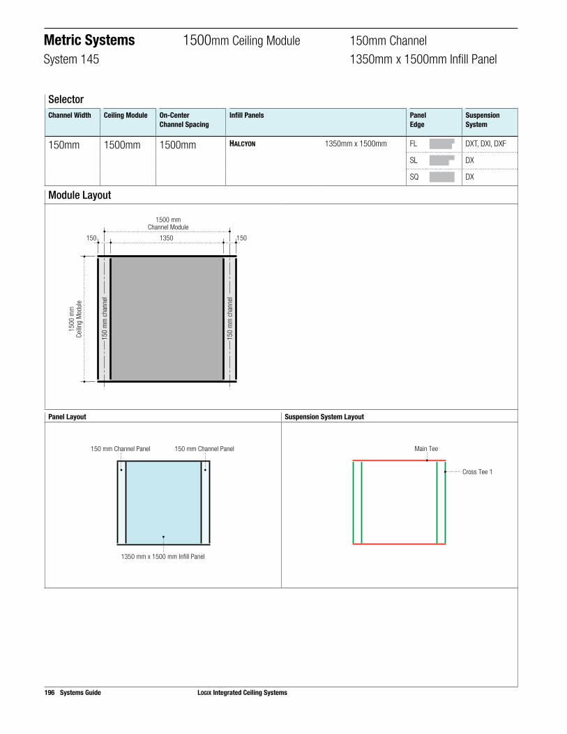
196 Systems Guide LOGIX Integrated Ceiling Systems
Panel Layout Suspension System Layout
1350 mm x 1500 mm Infill Panel
150 mm Channel Panel 150 mm Channel Panel
Main Tee
Cross Tee 1
Module Layout
150 1501350
1500 mmChannel Module
1500
mm
Ceilin
g M
odul
e
150
mm
cha
nnel
150
mm
cha
nnel
SelectorChannel Width Ceiling Module On-Center
Channel SpacingInfill Panels Panel
EdgeSuspension System
150mm 1500mm 1500mm HALCYON 1350mm x 1500mm FL DXT, DXI, DXF
SL DX
SQ DX
Metric Systems 1500mm Ceiling Module 150mm ChannelSystem 145 1350mm x 1500mm Infill Panel

Suspension System EstimatorLength m2 Main Tee
Usage Per m2Cross Tee 1Usage Per m2
System Module 1500mm 2.250 0.667 1.333
Note: Multiply the ceiling area (SF) by the Usage Factor (UF). This calculation will determine lineal footage of suspension system components required. Please refer to the front of this catalogue or IC592 for stabilizer bar usage.
Step 3. Select Corresponding Grid for Selected Panels
Order Information 1500mm Ceiling Module 150mm ChannelSystem 145 1350mm x 1500mm Infill Panel
FL/FLB SL/SLT SQ
Edge Item No. Edge Item No. Edge Item No.
Infill Panels HALCYON 1350mm x 1500mm FL ¨ ME97565 SL ¨ ME97536 SQ ¨ ME97507
Channel Panels HALCYON 150mm x 1500mm FL ¨ ME97573 SL ¨ ME97570 SQ ¨ ME97490
Qty Item No. Qty Item No. Qty Item No.
Suspension Systems
CENTRICITEE DXT Main Tee ¨ MEDXT24SP206
Cross Tee 1 2 ¨ MEDXT1500
IDENTITEE DXI Main Tee ¨ MEDXI24SP206
Cross Tee 1 2 ¨ MEDXI1500
DONN DX Main Tee 1 ¨ MEDX24SP206 ¨ MEDX24SP206
Cross Tee 1 2 ¨ MEDX1500 2 ¨ MEDX1500
LOGIX Integrated Ceiling Systems Systems Guide 197
Step 1. Select Panels Step 2. Select Edge for Panels
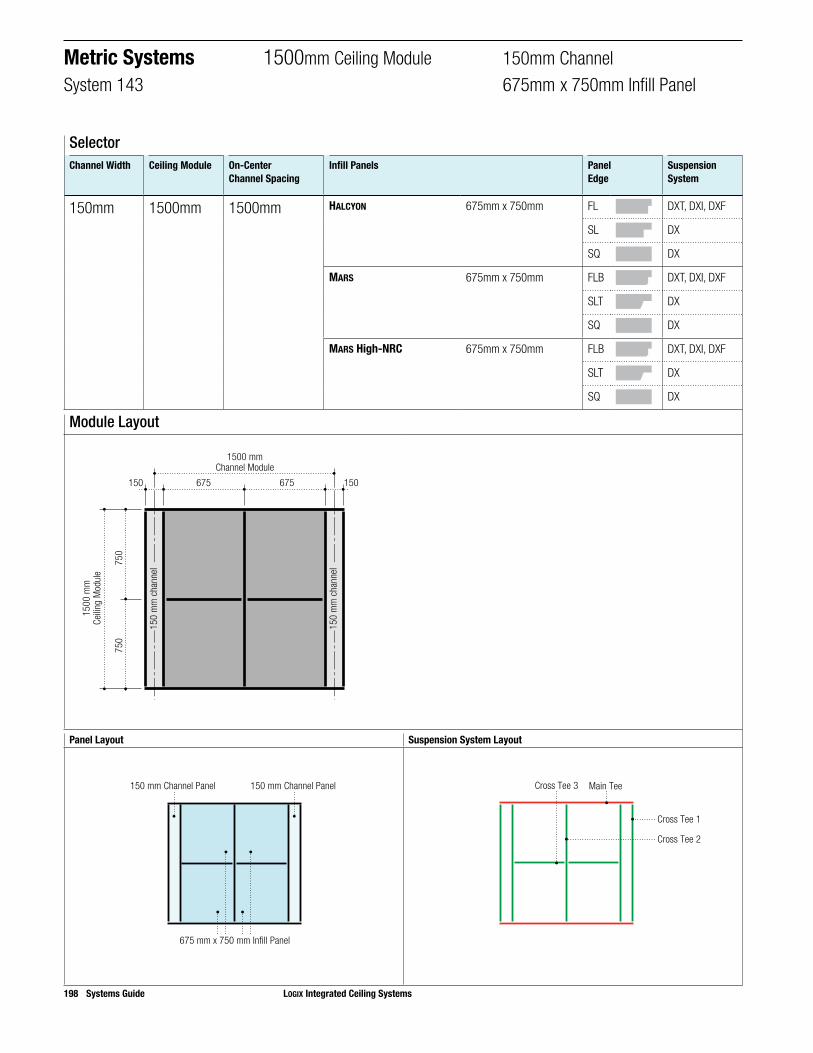
198 Systems Guide LOGIX Integrated Ceiling Systems
Panel Layout Suspension System Layout
675 mm x 750 mm Infill Panel
150 mm Channel Panel 150 mm Channel Panel
Main Tee
Cross Tee 1
Cross Tee 3
Cross Tee 2
Module Layout
675150 150675
750
750
1500 mmChannel Module
1500
mm
Ceilin
g M
odul
e
150
mm
cha
nnel
150
mm
cha
nnel
SelectorChannel Width Ceiling Module On-Center
Channel SpacingInfill Panels Panel
EdgeSuspension System
150mm 1500mm 1500mm HALCYON 675mm x 750mm FL DXT, DXI, DXF
SL DX
SQ DX
MARS 675mm x 750mm FLB DXT, DXI, DXF
SLT DX
SQ DX
MARS High-NRC 675mm x 750mm FLB DXT, DXI, DXF
SLT DX
SQ DX
Metric Systems 1500mm Ceiling Module 150mm ChannelSystem 143 675mm x 750mm Infill Panel

Suspension System EstimatorLength m2 Main Tee
Usage Per m2Cross Tee 1Usage Per m2
Cross Tee 2Usage Per m2
Cross Tee 3Usage Per m2
System Module 1500mm 1.500 1.000 2.000 1.000 0.900
Note: Multiply the ceiling area (SF) by the Usage Factor (UF). This calculation will determine lineal footage of suspension system components required. Please refer to the front of this catalogue or IC592 for stabilizer bar usage.
Step 3. Select Corresponding Grid for Selected Panels
Order Information 1500mm Ceiling Module 150mm ChannelSystem 143 675mm x 750mm Infill Panel
FL/FLB SL/SLT SQ
Edge Item No. Edge Item No. Edge Item No.
Infill Panels HALCYON 675mm x 750mm FL ¨ ME98333 SL ¨ ME97447 SQ ¨ ME97417
MARS 675mm x 750mm FLB ¨ ME86850 SLT ¨ ME86557 SQ ¨ ME86530
MARS High-NRC 675mm x 750mm FLB ¨ ME86490 SLT ¨ ME86458 SQ ¨ ME86421
Channel Panels HALCYON 150mm x 1500mm FL ¨ ME97573 SL ¨ ME97570 SQ ¨ ME97490
MARS 150mm x 1500mm FLB ¨ ME86835 SLT ¨ ME86543 SQ ¨ ME86507
MARS High-NRC 150mm x 1500mm FLB ¨ ME86333 SLT ¨ ME86443 SQ ¨ ME86145
Qty Item No. Qty Item No. Qty Item No.
Suspension Systems
CENTRICITEE DXT Main Tee ¨ MEDXT24SP206
Cross Tee 1 2 ¨ MEDXT1500
Cross Tee 2 1 ¨ MEDXT1500
Cross Tee 3 2 ¨ MEDXT675
IDENTITEE DXI Main Tee ¨ MEDXI24SP206
Cross Tee 1 2 ¨ MEDXI1500
Cross Tee 2 1 ¨ MEDXI1500
Cross Tee 3 2 ¨ MEDXI675
DONN DX Main Tee ¨ MEDX24SP206 ¨ MEDX24SP206
Cross Tee 1 2 ¨ MEDX1500 2 ¨ MEDX1500
Cross Tee 2 1 ¨ MEDX1500 1 ¨ MEDX1500
Cross Tee 3 2 ¨ MEDX675 2 ¨ MEDX675
LOGIX Integrated Ceiling Systems Systems Guide 199
Step 1. Select Panels Step 2. Select Edge for Panels

200 Systems Guide LOGIX Integrated Ceiling Systems
Panel Layout Suspension System Layout
1350 mm x 750 mm Infill Panel
150 mm Channel Panel 150 mm Channel Panel
Main Tee
Cross Tee 1
Cross Tee 2
Module Layout
1350150 150
750
750
1500 mmChannel Module
1500
mm
Ceilin
g M
odul
e
150
mm
cha
nnel
150
mm
cha
nnel
SelectorChannel Width Ceiling Module On-Center
Channel SpacingInfill Panels Panel
EdgeSuspension System
150mm 1500mm 1500mm HALCYON 1350mm x 750mm FL DXT, DXI, DXF
SL DX
SQ DX
MARS 1350mm x 750mm FLB DXT, DXI, DXF
SLT DX
SQ DX
MARS High-NRC 1350mm x 750mm FLB DXT, DXI, DXF
SLT DX
SQ DX
PANZ Metal Panels, Solid 1350mm x 750mm FL DXT, DXI
Metric Systems 1500mm Ceiling Module 150mm ChannelSystem 104 1350mm x 750mm Infill Panel

Suspension System EstimatorLength m2 Main Tee
Usage Per m2Cross Tee 1Usage Per m2
Cross Tee 2Usage Per m2
System Module 1500mm 2.250 0.667 1.333 0.600
Note: Multiply the ceiling area (SF) by the Usage Factor (UF). This calculation will determine lineal footage of suspension system components required. Please refer to the front of this catalogue or IC592 for stabilizer bar usage.
Step 3. Select Corresponding Grid for Selected Panels
FL/FLB SL/SLT SQ
Edge Item No. Edge Item No. Edge Item No.
Infill Panels HALCYON 1350mm x 750mm FL ¨ ME98359 SL ¨ ME98337 SQ ¨ ME97422
MARS 1350mm x 750mm FLB ¨ ME86831 SLT ¨ ME88686 SQ ¨ ME86503
MARS High-NRC 1350mm x 750mm FLB ¨ ME86501 SLT ¨ ME86464 SQ ¨ ME86427
PANZ Metal Panels, Solid 1350mm x 750mm FL ¨ ME909972
Channel Panels HALCYON 150mm x 1500mm FL ¨ ME97573 SL ¨ ME97570 SQ ¨ ME97490
MARS 150mm x 1500mm FLB ¨ ME86835 SLT ¨ ME86543 SQ ¨ ME86507
MARS High-NRC 150mm x 1500mm FLB ¨ ME86333 SLT ¨ ME86443 SQ ¨ ME86145
Qty Item No. Qty Item No. Qty Item No.
Suspension Systems
CENTRICITEE DXT Main Tee ¨ MEDXT24SP206
Cross Tee 1 2 ¨ MEDXT1500
Cross Tee 2 1 ¨ MEDXT1350
IDENTITEE DXI Main Tee ¨ MEDXI24SP206
Cross Tee 1 2 ¨ MEDXI1500
Cross Tee 2 1 ¨ MEDXI1350
DONN DX Main Tee ¨ MEDX24SP206 ¨ MEDX24SP206
Cross Tee 1 2 ¨ MEDX1500 2 ¨ MEDX1500
Cross Tee 2 1 ¨ MEDX1350 1 ¨ MEDX1350
Order Information 1500mm Ceiling Module 150mm ChannelSystem 104 1350mm x 750mm Infill Panel
LOGIX Integrated Ceiling Systems Systems Guide 201
Step 1. Select Panels Step 2. Select Edge for Panels

Notes
202 Systems Guide LOGIX Integrated Ceiling Systems

PRODUCT INFORMATIONSee usg.com for the most up-to-date product information.
INSTALLATIONMust be installed in compliance with ASTM C636, ASTM E580, CISCA and standard industry practices, within all applicable code requirements. Alternative assemblies and installation methods may be utilized when approved by the Authority Having Jurisdiction. USG recommends checking with the Authority Having Jurisdiction prior to designing and installing a suspended ceiling system.
CODE COMPLIANCEThe information presented is correct to the best of our knowledge at the date of issuance. Because codes continue to evolve, check with a local official prior to designing and install-ing a ceiling system. Other restrictions and exemptions may apply. This is only intended as a quick installation reference.
ICC EVALUATION SERVICE, INC., REPORT COMPLIANCESuspension systems manufactured by USG Interiors, Inc., have been reviewed and are approved by listing in ICC-Evaluation Service Report ESR-1222. Evaluation Reports are sub-ject to reexamination, revision and possible cancellation. Please refer to usgdesignstudio.com or usg.com for current reports.
L.A. RESEARCH REPORT ComplianceDonn brand suspension systems manufactured by USG Interiors, Inc., have been reviewed and are approved by listing in the following L.A. Research Report number: 25764.
NOTICEWe shall not be liable for incidental and consequential damages, directly or indirectly sustained, nor for any loss caused by applica-tion of these goods not in accordance with current printed instructions or for other than the intended use. Our liability is expressly limited to replacement of defective goods. Any claim shall be deemed waived unless made in writing to us within thirty (30) days from date it was or reasonably should have been discovered.
SAFETY FIRST! Follow good safety/industrial hygiene practices during installation. Wear appropriate personal protective equipment. Read MSDS and literature before specification and installation.
IS268/rev 10-14© 2014, USG Corporation or its affiliates. All rights reserved. The trademarks CENTRICITEE, DX, DXL, DONN, DXI, FINELINE, HALCYON, IDENTITEE, LOGIX, MARS, USG, IT’S YOUR WORLD BUILD IT, THE USG LOGO and related marks are trademarks of USG Interiors, LLC or a related company. GE Lighting Solutions, LLC is a subsidiary of the General Electric Company. The GE brand logo, Lumination are trademarks of the General Electric Company. © 2012 GE Lighting Solutions, LLC.
WEBSITESusg.comseismicceilings.comsustainableceilings.comusgdesignstudio.com
TECHNICAL SERVICE800 USG.4YOU (800 874.4968)
CUSTOMER SERVICE800 950.3839