using extra loudspeakers and sound … we do not recommend using local reinforcement in combination...
TRANSCRIPT

1
D1536505 Cisco TelePresence Using Extra Loudspeakers and Sound ReinforcementAll contents © 2016–2019 Cisco Systems, Inc. All rights reserved.
Cisco Webex SX80 and Codec Pro Based Systems
Using Extra Loudspeakers and Sound ReinforcementA guide to provide a better auditory experience
D1536505 Produced: March 2019 for CE9.7All contents © 2016–2019 Cisco Systems, Inc. All rights reserved

2
D1536505 Cisco TelePresence Using Extra Loudspeakers and Sound ReinforcementAll contents © 2016–2019 Cisco Systems, Inc. All rights reserved.
What’s in this guideContents
ContentsIntroduction ......................................................................................3Codec SX80: Use with Extra Loudspeakers (I) ...............................4Codec SX80: Use with Extra Loudspeakers (II) ...............................5Codec SX80: Expanding Scenario to Include Local Presenter (I) ...6Codec SX80: Expanding Scenario to Include Local Presenter (II)...7MX700/800: Use with Extra Loudspeakers .....................................8MX700/800: Use with Extra Loudspeakers .....................................9MX700/800: Expanding Scenario to Include Local Presenter .......10MX700/800: Expanding Scenario to Include Local Presenter ....... 11Codec Pro: Use with Extra Loudspeakers (I) .................................12Codec Pro: Use with Extra Loudspeakers (II) ................................13Codec Pro: Expanding to Include Local Presenter (I) ....................14Codec Pro: Expanding to Include Local Presenter (II) ...................15Audio Console — Customizing the Audio Connections ...................16The Audio Console Panel ..............................................................17Setting Up the Equalizer ................................................................18

3
D1536505 Cisco TelePresence Using Extra Loudspeakers and Sound ReinforcementAll contents © 2016–2019 Cisco Systems, Inc. All rights reserved.
Get Inspired
When using the Codec Pro or the SX80, you may want to use more than one pair of loudspeakers in the room to enhance the overall auditory experience.
When using the Codec Pro or SX80 with local sound reinforcement, extra loudspeakers are strongly recommended to ensure that people in the room get the good auditory experience.
To set up the system we recommend to use the Audio ConsoleNEW.
Alternatively, you may use parts of the API of the codec.
The use of Audio Console to set up a system for local reinforcement is discussed at the end of this document.
We recommend delaying the sound from the extra set of loudspeakers to take advantage of the Haas effect.
The Haas effect (also known as the Precedence effect) causes humans to localize sound sources in the direction of the first arriving sound despite the presence of a single reflection from a different direction. A single reflection arriving within 5–30 ms can be up to 10 dB louder than the direct sound without being perceived as a secondary auditory event.
To a listener located in sweet spot, the two extra loudspeakers will combine into a single phantom source and thus cause no violation of the single reflection requirement.
Introduction
Typical scenarios when a local presenter (lecturer) uses a wearable microphone and local reinforcement is used to enhance the auditory experience in the room.
In need of a little inspiration when it comes to designing video meeting scenarios?
Check out Project Workplace (https://projectworkplace.cisco.com/#/) which may serve as inspiration when you want to build your perfect meeting scenarios, explore our collaboration products, and discover experiences.
Typical scenarios when a codec is used with extra loudspeakers.
About Microphones and Echo Cancelling
If no more than 8 microphones are required, we do recommend that you stick to the 8 independent built-in echo cancelers of the codec. These are high-quality cancelers closely integrated with the internal mixer, loudspeaker sound processing and the general signal flow inside the codec.
The use of external echo cancelers will normally introduce additional delay with reduced lip-sync performance as a result. In addition, you will experience increased cost of installation and maintenance.
Note We do not recommend using local reinforcement in combination with SpeakerTrack.
Extra loudspeakers
Extra loudspeakers
Main loudspeakers
Main loudspeakers

4
D1536505 Cisco TelePresence Using Extra Loudspeakers and Sound ReinforcementAll contents © 2016–2019 Cisco Systems, Inc. All rights reserved.
Main loudspeakers
LAN
Local microphones
Touch 10Display(s)
Extra loudspeakers
Presentation source
(For clarity, no camera
connections are shown)
• Line outputs 1– 4 are standard “speaker outputs” (line level) that go through the volume control.
• Line outputs 5 and 6 are “record outputs” that contain local microphones as well as far end and program material.
• The example shown here reflects the codec’s standard behavior. This may easily be modified by means of the Audio Console (described later in this document).
Codec SX80: Use with Extra Loudspeakers (I) Connecting to the Codec
The illustration at left shows the external connections needed. Note that, for clarity, the camera connections have been omitted.
The illustration shows a configuration using passive loudspeakers and a power amplifier. Active loudspeakers (with built-in power amplifiers) may, of course, be used instead.
You may use any number of local microphones. Shown here is the maximum number the codec supports, which is 8 microphones — see also “About Microphones and Echo Cancelling” on page 3.
Your presentation source may be connected using either HDMI or DVI. In the latter case, audio must be provided separately to the codec, as shown.
For clarity, the HDMI PC-input audio alternative has been omitted in the illustration of the internal signal paths shown on the following page.

5
D1536505 Cisco TelePresence Using Extra Loudspeakers and Sound ReinforcementAll contents © 2016–2019 Cisco Systems, Inc. All rights reserved.
Codec SX80: Use with Extra Loudspeakers (II)
• For the initial configuration when setting this up, we recommend the use of a sound source connected to the video system as “local presentation outside a call”. Make sure you use a signal with a representative content and signal level, as well as sufficient dynamic range. Recorded speech should be a part of this signal.
• We recommend that level setting on the audio output connectors is kept at its default value (-10)
The extra loudspeakers’ level should then be set as suitable, using the loudspeakers’ own gain controls.
This will leave a range of –14 dB to +10 dB available for further adjustments, which will be needed if compensation for many people present in the room calls for a different level.
• Define a sweet spot (normally the position where things should sound the best).
• Measure the distance between the sweet spot and all of the loudspeakers, as shown at right.
• You should now introduce a delay to the sound from each of the extra loudspeakers.
This delay will correspond to the distances l1 – l3 and l2 – l4.
As a rule of thumb, use 3 ms delay per meter.
• A further 5–30 ms of delay should be added to the calculated delay difference to take advantage of the Haas effect — see page 3 for more on this.
The exact amount of delay is difficult to predict, try listening to the entire system while adjusting the delay. Use the sweet spot.
Ideally, you should hear a rich sound without being very much aware of the presence of the extra loudspeakers, while at the same time it should be clearly noticable when you switch off the extra loudspeakers.
• This delay adjustment may involve output level adjustment for the extra loudspeakers, but not necessarily.
• Use output level in the codec API to adjust the balance between the main and extra loudspeaker sets.
• The entire setup should then be tested with people in the room, alternatively with an amount of absorption material corresponding to such a situation.
This may call for further level adjustments, as outlined above.
• Be sure to make a video call to test that the far end experience has the quality required.
Sweet spot
l3
l2
l4
l1
The sweet spot is normally the position where things should sound the best. We recommend that you apply a delay setting to the extra loudspeakers to make things sound better. This will require that you measure the distances shown—see text for more.
PC-input audio & Far End audio sent to main
loudspeakers
Audio to Far End
GainMaster Volume
Adaptive echo cancelers
Delay
Gain
PC-input audio
Audio from Far End (including any Far End PC-input audio)
SX80
PC-input audio and
Far End audio sent
to extra loudspeakers
PC-input audio
PC-input audio

6
D1536505 Cisco TelePresence Using Extra Loudspeakers and Sound ReinforcementAll contents © 2016–2019 Cisco Systems, Inc. All rights reserved.
Main loudspeakers
Wireless microphone for local presenter
Wireless microphone base station
LAN
Touch 10Display(s)
Extra loudspeakers
Presentation source
Local microphones
(For clarity, no camera
connections are shown)
• Line outputs 1– 4 are standard “speaker outputs” (line level) that go through the volume control.
• Line outputs 5 and 6 are “record outputs” that contain local microphones as well as far end and program material.
• The example shown here reflects the codec’s standard behavior. This may easily be modified by means of the Audio Console (described later in this document).
Codec SX80: Expanding Scenario to Include Local Presenter (I) Connecting to the Codec
The illustration at left shows the external connections needed when expanding the scenario to include a local presenter. The only difference from the original scenario is the introduction of a wireless microphone and its base station (shown in green). The use of a wireless microphone is not mandatory, wired microphones may also be used. In addition, you may also use any of the microphone inputs for the local presenter. If you need more than one for this, use the number needed, just observe the danger of feedback if care has not been taken (see the following page for more on this).
Note that, for clarity, the camera connections have been omitted.
The illustration shows a configuration using passive loudspeakers and a power amplifier. Active loudspeakers (with built-in power amplifiers) may, of course, be used instead.
You may use any number of local microphones. Shown here is the maximum number the codec supports, which is 8 microphones — see also “About Microphones and Echo Cancelling” on page 3.
In the illustration, the wireless microphone is connected to Input No.1, but you may connect it to any of the 8 Inputs.
Your presentation source may be connected using either HDMI or DVI. In the latter case, audio must be provided separately to the codec, as shown.
For clarity, the HDMI PC-input audio alternative has been omitted in the illustration of the internal signal paths shown on the following page.

7
D1536505 Cisco TelePresence Using Extra Loudspeakers and Sound ReinforcementAll contents © 2016–2019 Cisco Systems, Inc. All rights reserved.
Codec SX80: Expanding Scenario to Include Local Presenter (II)
• We assume that you have already set up your SX80 to work with a set of extra loudspeakers, as described on the previous page.
• Use a dedicated (and closely mounted) microphone for the presenter, preferably of the wearable type.
This will ensure high quality audio with low loudness variation from the presenter and low sensitivity towards other audio sources. It is important that the presenter microphone does not pick up much of the audio from the loudspeakers, when local reinforcement of the presenter audio is used.
This serves to avoid strong reverberation, coloration and in the worst case feedback, of the presenter audio.
Other microphones in the room, e.g. ceiling mounted microphones may still be operating, but not as a substitute for the personal microphone.
• The wearable microphone will typically be of the wireless type with a base station.
In order to avoid clipping of the codec’s microphone input, you may want to set the base station output to Mic out, rather than Line out.
If you do so, make sure the base station is not suffering damage from the phantom voltage supplied by the codec. See also Appendix for more.
• Another strategy will be to use Line out of the base station and reduce the input sensitivity of the codec accordingly.
The codec full scale level is 22 dBu. If you have a base station supplying e.g. 18 dBu, you should not set the codec input level higher than 4.
Each step of the codec input level setting corresponds to 1dB gain. For more on this, consult the SX80 Physical Interface Guide.
• Furthermore, we do recommend that any kind of processing in the base station is avoided. We are here thinking of such things as dynamic EQ, compression, noise reduction, AGC, de-essing etc. These types of time-varying and/or non-linear processing may be detrimental to the codec’s echo cancelling performance. Fixed EQ, however, should cause no problem.
• The input signal level from the wearable microphone should be checked using the VU-meter feature of the codec. Green with occassional appearances of yellow is considered good. Note that there is no peak hold, so testing by listening will be needed. Use the gain control of the microphone base station to adjust the microphone level, if needed.
• Adjust the gain settings so that the codec input levels are the same for all microphone inputs, for a given sound level.
Should you now need to adjust the sound level, use the following guidelines:
• Use Mixer Gain of the Audio Console to amplify the local presenter.
• Use Master Volume to amplify PC-input audio and far-end audio. The local presenter will not be affected by this.
• You may want to fine-tune the delay at this stage.
• The entire setup should then be tested with people in the room, alternatively with an amount of absorption material corresponding to such a situation.
This may call for further level adjustments, as outlined above.
• Be sure to make a video call to test that the far end experience has the quality required.
In the below example two microphones are used for the local reinforcement, feel free to use any number of the 8 microphones.
Note We do not recommend that you combine local reinforcement and SpeakerTrack.
Local presenter, PC-input
audio and Far End
audio sent to extra
loudspeakers
PC-input audio & Far End audio sent to main
loudspeakers
Microphones for local
presenter
Audio to Far End
Gain
Gain
Master Volume
Microphone reinforcement gain
Adaptive echo cancelers
Delay
Gain
PC-input audio
PC-input audio
PC-input audio
Audio from Far End (including any Far End PC-input audio)
SX80
8
D1536505 Cisco TelePresence Using Extra Loudspeakers and Sound ReinforcementAll contents © 2016–2019 Cisco Systems, Inc. All rights reserved.
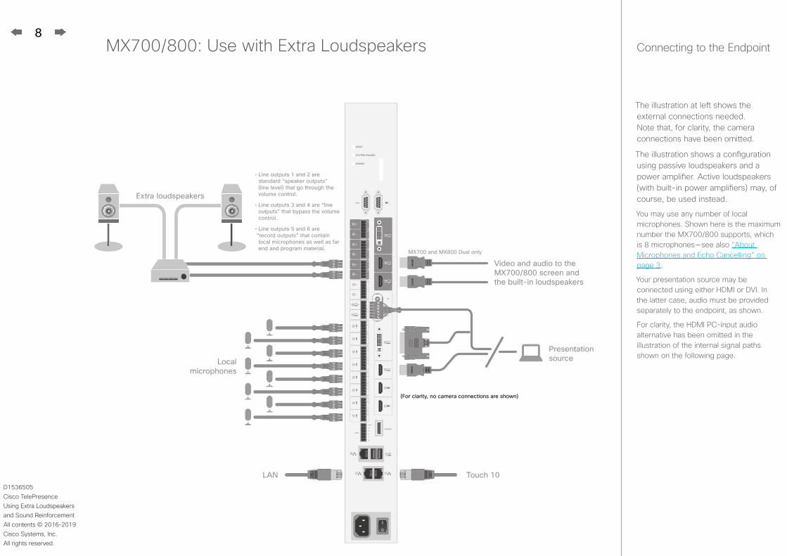
MX700/800: Use with Extra Loudspeakers Connecting to the Endpoint
The illustration at left shows the external connections needed. Note that, for clarity, the camera connections have been omitted.
The illustration shows a configuration using passive loudspeakers and a power amplifier. Active loudspeakers (with built-in power amplifiers) may, of course, be used instead.
You may use any number of local microphones. Shown here is the maximum number the MX700/800 supports, which is 8 microphones — see also “About Microphones and Echo Cancelling” on page 3.
Your presentation source may be connected using either HDMI or DVI. In the latter case, audio must be provided separately to the endpoint, as shown.
For clarity, the HDMI PC-input audio alternative has been omitted in the illustration of the internal signal paths shown on the following page.
LAN
Presentation sourceLocal
microphones
Extra loudspeakers
(For clarity, no camera connections are shown)
Touch 10
MX700 and MX800 Dual only
Video and audio to the MX700/800 screen and the built-in loudspeakers
• Line outputs 1 and 2 are standard “speaker outputs” (line level) that go through the volume control.
• Line outputs 3 and 4 are “line outputs” that bypass the volume control.
• Line outputs 5 and 6 are “record outputs” that contain local microphones as well as far end and program material.

9
D1536505 Cisco TelePresence Using Extra Loudspeakers and Sound ReinforcementAll contents © 2016–2019 Cisco Systems, Inc. All rights reserved.
• For the initial configuration when setting this up, we recommend the use of a sound source connected to the video system as “local presentation outside a call”. Make sure you use a signal with a representative content and signal level, as well as sufficient dynamic range. Recorded speech should be a part of this signal.
• We recommend that level setting on the audio output connectors is kept at its default value (-10).
The extra loudspeakers’ level should then be set as suitable, using the loudspeakers’ own gain controls.
This will leave a range of –14 dB to +10 dB available for further adjustments, which will be needed if compensation for many people present in the room calls for a different level.
• Define a sweet spot (normally the position where things should sound the best).
• Measure the distance between the sweet spot and both of the extra loudspeakers, as well as the distance between the sweet spot and the video system, as shown at right.
• You should now introduce a delay to the sound from each of the external loudspeakers.
This delay will correspond to the distances ls – l3 and ls – l4.
As a rule of thumb, use 3 ms delay per meter.
• A further 5–30 ms of delay should be added to the calculated delay difference to take advantage of the Haas effect — see page 3 for more on this.
The exact amount of delay is difficult to predict, try listening to the entire system while adjusting the delay. Use the sweet spot.
Ideally, you should hear a rich sound without being very much aware of the presence of the external loudspeakers, while at the same time it should be clearly noticable when you switch off the external loudspeakers.
• This delay adjustment may involve output level adjustments, but not necessarily.
• Use Output level in the codec API to adjust the balance between the integrated and extra loud-speakers.
• The entire setup should then be tested with people in the room, alternatively with an amount of absorption material corresponding to such a situation.
This may call for further level adjustments, as outlined above.
• Be sure to make a video call to test that the far end experience has the quality required.
MX700/800: Use with Extra Loudspeakers
Sweet spot
l3 l4ls
Adaptive echo cancelers
PC-input audio
PC-input audio
Audio to Far EndAudio from Far End (including any Far End PC-input audio)
MX700/800
PC-input audio and
Far End audio sent to extra loudspeakers
DelayGain
Master Volume
Gain
PC-input audio and Far End audio sent to built-in loudspeakers
The sweet spot is normally the position where things should sound the best. We recommend that you apply a
delay setting to the extra loudspeakers to make things sound better. This will require that you measure the distances shown—
see text for more.
We do recommend the use of “Audio Console — Customizing the Audio Connections” on page 16 to set up this behavior.

10
D1536505 Cisco TelePresence Using Extra Loudspeakers and Sound ReinforcementAll contents © 2016–2019 Cisco Systems, Inc. All rights reserved.
MX700/800: Expanding Scenario to Include Local Presenter Connecting to the Endpoint
LAN Touch 10
Presentation source
Wireless microphone for local presenter
Wireless microphone base station
(For clarity, no camera connections are shown)
Local microphones
Extra loudspeakers
Video and audio to the MX700/800 screen and the built-in loudspeakers
MX700 and MX800 Dual only
• Line outputs 1 and 2 are standard “speaker outputs” (line level) that go through the volume control.
• Line outputs 3 and 4 are “line outputs” that bypass the volume control.
• Line outputs 5 and 6 are “record outputs” that contain local microphones as well as far end and program material.
Wireless microphone base station
The illustration at left shows the external connections needed when expanding the scenario to include a local presenter. The only difference from the original scenario is the introduction of a wireless microphone and its base station (shown in green). The use of a wireless microphone is not mandatory, wired microphones may also be used. In addition, you may also use any of the microphone inputs for the local presenter. If you need more than one for this, use the number needed, just observe the danger of feedback if care has not been taken (see the following page for more on this).
Note that, for clarity, the camera connections have been omitted.
The illustration shows a configuration using passive loudspeakers and a power amplifier. Active loudspeakers (with built-in power amplifiers) may, of course, be used instead.
You may use any number of local microphones. Shown here is the maximum number the MX700/800 supports, which is 8 microphones — see also “About Microphones and Echo Cancelling” on page 3.
In the illustration, the wireless microphone is connected to Input No.1, but you may connect it to any of the 8 Inputs.
Your presentation source may be connected using either HDMI or DVI. In the latter case, audio must be provided separately to the endpoint, as shown.
For clarity, the HDMI PC-input audio alternative has been omitted in the illustration of the internal signal paths shown on the following page.

11
D1536505 Cisco TelePresence Using Extra Loudspeakers and Sound ReinforcementAll contents © 2016–2019 Cisco Systems, Inc. All rights reserved.
MX700/800: Expanding Scenario to Include Local Presenter
• We assume that you have already set up your MX700/800 to work with a set of extra loudspeakers, as described on the previous page.
• Use a dedicated (and cloesly mounted) microphone for the presenter, preferably of the wearable type.
This will ensure high quality audio with low loudness variation from the presenter and low sensitivity towards other audio sources. It is important that the presenter mi-crophone does not pick up much of the audio from the built-in loudspeakers of the MX700/800 or the extra loudspeakers, when local reinforcement of the pre-senter audio is used.
This serves to avoid strong reverberation, coloration and in the worst case feedback, of the presenter audio.
Other microphones in the room, e.g. ceiling mounted microphones may still be operating, but not as a substitute for the personal microphone.
• The wearable microphone will typically be of the wireless type with a base station.
In order to avoid clipping of the codec’s microphone input, you may want to set the base station output to Mic out, rather than Line out.
If you do so, make sure the base station is not suffering damage from the phantom voltage supplied
by the codec. See also Appendix for more.
• Another strategy will be to use Line out of the base station and reduce the input sensitivity of the codec accordingly.
The codec full scale level is 22 dBu. If you have a base station supplying e.g. 18 dBu, you should not set the codec input level higher than 4.
Each step of the codec input level setting corresponds to 1dB gain. For more on this, consult the SX80 Physical Interface Guide.
• Furthermore, we do recommend that any kind of processing in the base station is avoided. We are here thinking of such things as dynamic EQ, compression, noise reduction, AGC, de-essing etc. These types of time-varying and/or non-linear processing may be detrimental to the codec’s echo cancelling performance. Fixed EQ, however, should cause no problem.
• The input signal level from the wearable microphone should be checked using the VU-meter feature of the codec. Green with occassional appearances of yellow is considered good. Note that there is no peak hold, so testing by listening will be needed. Use the gain control of the microphone base station to adjust the microphone level, if needed.
• Adjust the gain settings so that the codec input levels are the same for all microphone inputs, for a given sound level.
Should you now need to adjust the sound level, use the following guidelines:
• Use MicrophoneReinforce-ment Gain to amplify the local presenter.
• Use Master volume to amplify PC-input audio and far-end audio. This will not influence the level of the local presenter.
• You may want to fine-tune the delay at this stage.
• Finally, the entire setup should then be tested with people in the room, alternatively with an amount of absorption material corresponding to such a situation.
This may call for further level adjustments, as outlined above.
• Be sure to make a video call to test that the far end experience has the quality required.
In the above example two microphones are used for the local reinforcement. This is just an example, feel free to use any number of the 8 microphones.
Note We do not recommend that you combine local reinforcement and SpeakerTrack.
PC-input audio and Far End audio sent to built-in loudspeakers
Microphones for local presenter
DelayGain
Gain Microphone reinforcement gain
Adaptive echo cancelers
Gain
PC-input audio
PC-input audio
Audio to Far EndAudio from Far End (including any Far End PC-input audio)
MX700/800
Local presenter, PC-input audio and
Far End audio sent to extra loudspeakersMaster Volume
We do recommend the use of “Audio Console — Customizing the Audio Connections” on page 16 to set up this behavior.

12
D1536505 Cisco TelePresence Using Extra Loudspeakers and Sound ReinforcementAll contents © 2016–2019 Cisco Systems, Inc. All rights reserved.
Codec Pro: Use with Extra Loudspeakers (I) Connecting to the Codec
The Codec Pro section of this document applies to Cisco Room 70 G2 as well.
The illustration at left shows the external connections needed.
You may use any number of local microphones (up to 8) — see also “About Microphones and Echo Cancelling” on page 3.
Network (LAN)
Computer (for presentation)
Microphones, max 8
Presentation Display
Remote Presenter Display
Touch 10
Audience Camera
Loudspeakers, mono or stereo Power
Remote Audience Display
Loudspeakers must be active or connected to a power amplifier.
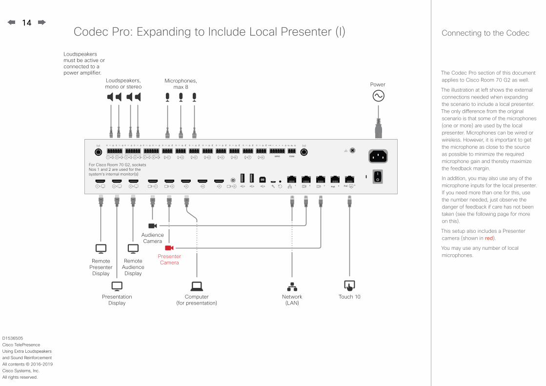
For Cisco Room 70 G2, sockets Nos 1 and 2 are used for the system’s internal monitor(s)

13
D1536505 Cisco TelePresence Using Extra Loudspeakers and Sound ReinforcementAll contents © 2016–2019 Cisco Systems, Inc. All rights reserved.
Codec Pro: Use with Extra Loudspeakers (II)
PC-input audio
Audio to Far End
Adaptive echo cancelers
GainMaster Volume
Delay
Gain
PC-input audio
and Far End audio
sent to main loudspeakers
PC-input audio & Far End audio sent to extra loudspeakers
Audio from
Far End
(including any Far End PC-input audio)
Audio to Far End
PC-input audio
• For the initial configuration when setting this up, we recommend the use of a sound source connected to the video system as “local presentation outside a call”. Make sure you use a signal with a representative content and signal level, as well as sufficient dynamic range. Recorded speech should be a part of this signal.
• We recommend that level setting on the audio output connectors is kept at its default value (-4)
The extra loudspeakers’ level should then be set as suitable, using the loudspeakers’ own gain controls.
This will leave a range of –20 dB to +4 dB available for further adjustments, which will be needed if compensation for many people present in the room calls for a different level.
• Define a sweet spot (normally the position where things should sound the best).
• Measure the distance between the sweet spot and all of the loudspeakers, as shown at right.
• You should now introduce a delay to the sound from each of the extra loudspeakers.
This delay will correspond to the distances l1 – l3 and l2 – l4.
As a rule of thumb, use 3 ms delay per meter.
• A further 5–30 ms of delay should be added to the calculated delay difference to take advantage of the Haas effect — see page 3 for more on this.
The exact amount of delay is difficult to predict, try listening to the entire system while adjusting the delay. Use the sweet spot.
Ideally, you should hear a rich sound without being very much aware of the presence of the extra loudspeakers, while at the same time it should be clearly noticable when you switch off the extra loudspeakers.
• This delay adjustment may involve output level adjustment for the extra loudspeakers, but not necessarily.
• Use output level in the codec API to adjust the balance between the main and extra loudspeaker sets.
• The entire setup should then be tested with people in the room, alternatively with an amount of absorption material corresponding to such a situation.
This may call for further level adjustments, as outlined above.
• Be sure to make a video call to test that the far end experience has the quality required.
l3
l2
l4
l1
The sweet spot is normally the position where things should sound the best. We recommend that you apply a delay setting to the extra loudspeakers to make things sound better. This will require that you measure the distances shown—see text for more.
The below illustration shows the internal signal paths of the Codec Pro when used for local reinforcement with extra loudspeakers.
Tip: Use Audio Console to set things up in a web browser.
14
D1536505 Cisco TelePresence Using Extra Loudspeakers and Sound ReinforcementAll contents © 2016–2019 Cisco Systems, Inc. All rights reserved.
Codec Pro: Expanding to Include Local Presenter (I) Connecting to the Codec
The Codec Pro section of this document applies to Cisco Room 70 G2 as well.
The illustration at left shows the external connections needed when expanding the scenario to include a local presenter. The only difference from the original scenario is that some of the microphones (one or more) are used by the local presenter. Microphones can be wired or wireless. However, it is important to get the microphone as close to the source as possible to minimize the required microphone gain and thereby maximize the feedback margin.
In addition, you may also use any of the microphone inputs for the local presenter. If you need more than one for this, use the number needed, just observe the danger of feedback if care has not been taken (see the following page for more on this).
This setup also includes a Presenter camera (shown in red).
You may use any number of local microphones.
Loudspeakers must be active or connected to a power amplifier.
Network (LAN)
Computer (for presentation)
Microphones, max 8
Presentation Display
Remote Presenter Display
Touch 10
Audience Camera
Presenter Camera
Power
Remote Audience Display
Loudspeakers, mono or stereo
For Cisco Room 70 G2, sockets Nos 1 and 2 are used for the system’s internal monitor(s)

15
D1536505 Cisco TelePresence Using Extra Loudspeakers and Sound ReinforcementAll contents © 2016–2019 Cisco Systems, Inc. All rights reserved.
Codec Pro: Expanding to Include Local Presenter (II)
• We assume that you have already set up your Codec Pro to work with a set of extra loudspeakers, as described on the previous pages.
• Use a dedicated (and closely mounted) microphone for the presenter, preferably of the wearable type.
This will ensure high quality audio with low loudness variation from the presenter and low sensitivity towards other audio sources. It is important that the presenter microphone does not pick up much of the audio from the loudspeakers, when local reinforcement of the presenter audio is used.
This serves to avoid strong reverberation, coloration and in the worst case feedback, of the presenter audio.
Other microphones in the room, e.g. ceiling mounted microphones may still be operating, but not as a substitute for the personal microphone.
• The wearable microphone will typically be of the wireless type with a base station.
In order to avoid clipping of the codec’s microphone input, you may want to set the base station output to Mic out, rather than Line out.
If you do so, make sure the base station is not suffering damage from the phantom voltage supplied by the codec.
• Another strategy will be to use Line out of the base station and reduce the input sensitivity of the codec accordingly.
The codec full scale level is 22 dBu. If you have a base station supplying e.g. 18 dBu, you should not set the codec input level higher than 4.
Each step of the codec input level setting corresponds to 1dB gain. For more on this, consult the Codec Pro Physical Interface Guide.
• Furthermore, we do recommend that any kind of processing in the base station is avoided. We are here thinking of such things as dynamic EQ, compression, noise reduction, AGC, de-essing etc. These types of time-varying and/or non-linear processing may be detrimental to the codec’s echo cancelling performance. Fixed EQ, however, should cause no problem.
• The input signal level from the wearable microphone should be checked using the VU-meter feature of the codec. Green with occassional appearances of yellow is considered good. Note that there is no peak hold, so testing by listening will be needed. Use the gain control of the microphone base station to adjust the microphone level, if needed.
• Adjust the gain settings so that the codec input levels are the same for all microphone inputs, for a given sound level.
Should you now need to adjust the sound level, use the following guidelines:
• Use Audio Console to amplify the local presenter.
• Use Master Volume to amplify PC-input audio and far-end audio. The local presenter will not be affected by this. Applies when the Output Group has been set to be Volume Controlled only.
• You may want to fine-tune the delay at this stage.
• The entire setup should then be tested with people in the room, alternatively with an amount of absorption material corresponding to such a situation.
This may call for further level adjustments, as outlined above.
• Be sure to make a video call to test that the far end experience has the quality required.
In the below example two microphones are used for the local reinforcement, feel free to use any number of the 8 microphones.
Note We do not recommend that you combine local reinforcement and SpeakerTrack.
The below illustration shows the internal signal paths of the Codec Pro when used for local reinforcement with extra loudspeakers and local presenter.
Audio to Far End
Adaptive echo cancelers
GainMaster Volume
Delay
Gain
PC-input audio
and Far End audio
sent to main loudspeakers
PC-input audio & Far End audio sent to extra loudspeakers
Microphones for local presenter
Audio from
Far End
(including any Far End PC-input audio)
Audio to Far End
PC-input audio
PC-input audio
Gain

16
D1536505 Cisco TelePresence Using Extra Loudspeakers and Sound ReinforcementAll contents © 2016–2019 Cisco Systems, Inc. All rights reserved.
The Audio Console utility lets you define how audio inputs and outputs should be connected together, using simple drag and drop.
The Audio Console is available for systems using SX80 and Codec Pro.
The Audio Console can be found under Setup in the Web interface of your video system.
You start by defining logical input and output groups. The physical inputs and outputs are then assigned to those logical inputs and outputs.
New logical input and output groups may be added at all times. Likewise, you may remove logical modules at all times.
Changes applied to the settings are immediately put into effect. In this version saving has been automated, no need to worry!NEW
The logical input and output groups can be given names defined by you.
A physical input, e.g. a microphone, can be assigned to more than one input. This comes in handy when working with local reinforcement, typically using a video system in lecture halls where the local audience also needs to hear what is being said through the microphone.
The Audio Console setup lets you utilize Echo Control on the part of the microphone signal that is sent to the far end, but at the same time omitting it for the part used locally (by assigning that microphone to more than one logical group). Use Direct On for this, see the next page for more on this..
You may also apply noise reduction and equalizer settings to the microphone signal.
A physical output cannot be assigned to more than a single logical output group.
In the Codec Pro, a Microphone input is a Line input with Phantom Feeding activated.
Using Audio Return Channels
HDMI offers, under certain circumstances, the ability to transmit audio in either direction. When audio is sent in reverse, this is referred to as an Audio Return Channel (ARC). The Codec Pro supports this.
Consider the below configuration, showing a Cisco QuadCam (top), a monitor (middle), and a Codec Pro (bottom) connected via HDMI. The QuadCam will act as both camera and soundbar in this setting.
During normal use, the HDMI1 is used to provide the Codec Pro with video from the cameras of the QuadCam unit and the audio return channel of the same will be used to route the audio from the Codec Pro to the loudspeakers of the QuadCam.
However, if you want to use the setup as just a TV with a soundbar, the system will send audio from the monitor to the Codec Pro through HDMI out 1 (ARC) of Codec Pro and the Codec Pro will send that audio further to the QuadCam through HDMI1 in (ARC).
In order to be able to do this, the monitor must be CEC+ARC enabled. If your setup makes use of 4k video, make sure the monitor supports CEC+ARC in 4k format.
Audio Console — Customizing the Audio Connections Where are the VU-meters?
To display the VU-meters, sign in to the web interface of the codec, then navigate to Setup > Peripherals and then down to the microphone VU-meters.
Alternatively go to Settings > Issues and Diagnostics > Microphone check on the Touch10 to display a VU-meter per microphone.
1 2
17
D1536505 Cisco TelePresence Using Extra Loudspeakers and Sound ReinforcementAll contents © 2016–2019 Cisco Systems, Inc. All rights reserved.
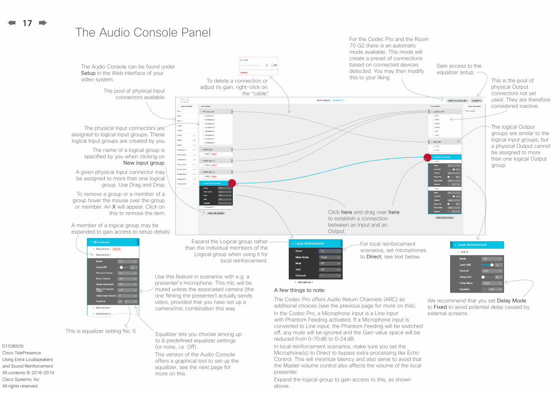
The Audio Console Panel
A few things to note:
The Codec Pro offers Audio Return Channels (ARC) as additional choices (see the previous page for more on this).In the Codec Pro, a Microphone input is a Line input with Phantom Feeding activated. If a Microphone input is converted to Line input, the Phantom Feeding will be switched off, any mute will be ignored and the Gain value space will be reduced from 0–70 dB to 0–24 dB.In local reinforcement scenarios, make sure you set the Microphone(s) to Direct to bypass extra processing like Echo Control. This will minimize latency and also serve to avoid that the Master volume control also affects the volume of the local presenter.Expand the logical group to gain access to this, as shown above.
The pool of physical Input connectors available.
This is the pool of physical Output connectors not yet used. They are therefore considered inactive.
The physical Input connectors are assigned to logical Input groups. These logical Input groups are created by you.
The name of a logical group is specified by you when clicking on
New input group.
A given physical Input connector may be assigned to more than one logical
group. Use Drag and Drop.
To remove a group or a member of a group hover the mouse over the group or member. An X will appear. Click on
this to remove the item.
The logical Output groups are similar to the logical Input groups, but a physical Output cannot be assigned to more than one logical Output group.
Click here and drag over here to establish a connection between an Input and an Output.
To delete a connection or adjust its gain, right-click on
the “cable”.
Equalizer lets you choose among up to 8 predefined equalizer settings (or none, i.e. Off).This version of the Audio Console offers a graphical tool to set up the equalizer, see the next page for more on this.
Gain access to the equalizer setup.
The Audio Console can be found under Setup in the Web interface of your video system.
A member of a logical group may be expanded to gain access to setup details:
Expand the Logical group rather than the individual members of the
Logical group when using it for local reinforcement.
For the Codec Pro and the Room 70 G2 there is an automatic mode available. This mode will create a preset of connections based on connected devices detected. You may then modify this to your liking.
This is equalizer setting No. 5
We recommend that you set Delay Mode to Fixed to avoid potential delay caused by external screens.
For local reinforcement scenarios, set microphones to Direct, see text below.
Use this feature in scenarios with e.g. a presenter’s microphone. This mic will be muted unless the associated camera (the one filming the presenter) actually sends video, provided that you have set up a camera/mic combination this way.
18
D1536505 Cisco TelePresence Using Extra Loudspeakers and Sound ReinforcementAll contents © 2016–2019 Cisco Systems, Inc. All rights reserved.
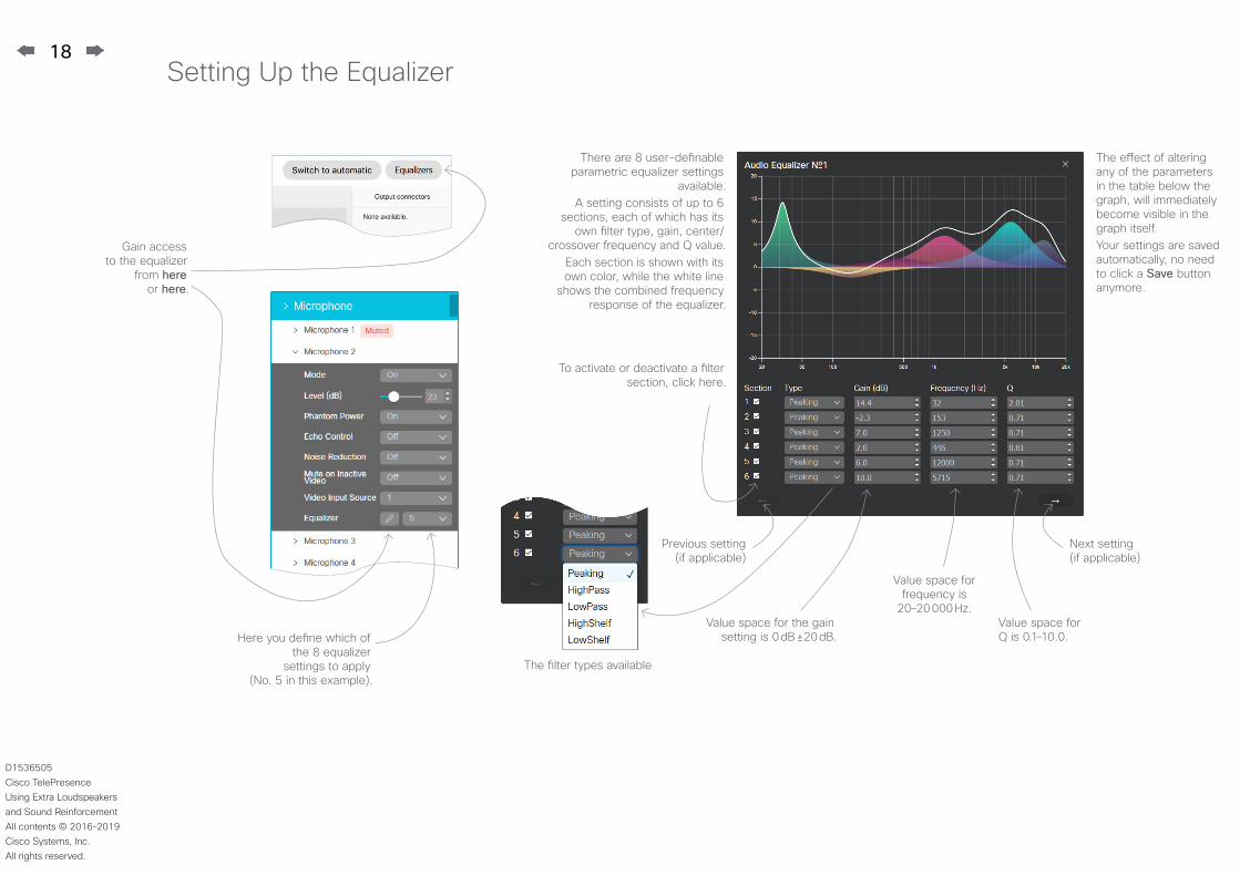
Setting Up the Equalizer
There are 8 user-definable parametric equalizer settings
available.A setting consists of up to 6
sections, each of which has its own filter type, gain, center/
crossover frequency and Q value.Each section is shown with its own color, while the white line
shows the combined frequency response of the equalizer.
To activate or deactivate a filter section, click here.
The filter types available
Gain access to the equalizer
from here or here.
Here you define which of the 8 equalizer
settings to apply (No. 5 in this example).
Next setting (if applicable)
Previous setting (if applicable)
Value space for the gain setting is 0 dB ±20 dB.
Value space for frequency is
20–20 000 Hz.Value space for Q is 0.1–10.0.
The effect of altering any of the parameters in the table below the graph, will immediately become visible in the graph itself.Your settings are saved automatically, no need to click a Save button anymore.

Cisco has more than 200 offices worldwide. Addresses, phone numbers, and fax numbers are listed on the Cisco Website at www.cisco.com/go/offices.
Cisco and the Cisco Logo are trademarks of Cisco Systems, Inc. and/or its affiliates in the U.S. and other countries. A listing of Cisco’s trademarks can be found at www.cisco.com/go/trademarks. Third party trademarks mentioned are the property of their respective owners. The use of the word partner does not imply a partnership relationship between Cisco and any other company. (1005R)
Americas Headquarters Cisco Systems, Inc. San Jose, CA
Asia Pacific Headquarters Cisco Systems (USA) Pte. Ltd. Singapore
Europe Headquarters Cisco Systems International BV Amsterdam, The Netherlands