using musical acoustics federico pedersini, augusto sarti...
TRANSCRIPT

NOVEMBER 2000 IEEE SIGNAL PROCESSING MAGAZINE 37
Using Musical Acoustics
Federico Pedersini, Augusto Sarti, and Stefano Tubaro
The physical modeling of complex sound genera-tors can only be approached by individually syn-thesizing and discretizing the objects thatcontribute to the generation of sounds. This
raises the problem of how to correctly implement the inter-action between these objects. In this article we show how toconstruct an object-basedenvironment for soundgeneration, whose ob-jects can be individuallysynthesized and whichcan interact with eachother through the mod-eling of a potential interaction topology. We will also showhow this interaction topology can be made dynamic andtime varying. We will further discuss how we envision anobject-based environment that integrates geometric, radio-metric, and intrinsic/extrinsic acoustic properties. We willfinally illustrate our first results toward the modeling ofcomplex sound generation systems.
BackgroundRecent achievements in the areas of computer vision, dig-ital image processing, and computer graphics have madeit possible to model realistic visual three-dimensional(3-D) environments [17], [27], [31], [33], [72], [2]and 3-D objects [4], [68], [39], [52]-[55] with effortsand costs that tend to decrease day by day. At the same
time, a great deal of effort has also been spent in the areaof audio analysis, synthesis, and processing, which hasbrought significant results in the perceptual encod-ing/compression of natural audio [10], in the realistic pro-duction of synthetic sounds [48], [20], [6], [8] and intheir realistic spatialization [29], [36], [46], [47], [70].Behind this tidal wave of results is an exponential increaseof computational power at low cost, combined with anever more capillary diffusion of domestic Internet con-nections and a consequent explosion of new forms of net-worked services. An attempt to prevent research from
producing just a disorganized collection of heterogeneousresults has been made by the MPEG standardizationboard, which in the past few years has spent tremendousefforts toward a standardization for multimedia encod-ing/decoding and document retrieval and is still workingtoward this goal. This effort has encouraged the research
community to channelthe new results withinthe standards and hasmotivated technologyproviders to focuson the productionof low-cost multi-
media set-top boxes that could enable even computer-il-literate users to access shared networked virtualenvironments.
In the past decade, the market has been preparing itselffor the maturing of the technology related to the creation ofinteractive multimedia environments. In fact, electroniccommerce, with virtual shopping centers and marketplaces, is already a booming reality. All this is creating a tre-mendous demand for authoring tools that could speed upthe process of creation and personalization of these envi-ronments, which are expected to become more and morerealistic in the near future. The concept of virtual universityis also stirring a great deal of interest as more and more aca-demic institutions are getting ready to become didacticproviders for remote learners.
In spite of the abundance of results in the manyareas of interest for multimedia applications, little hasbeen done for synergically exploiting those that concernsynthetic and natural modeling/rendering of visual 3-Denvironments and acoustic 3-D environments. From acertain viewpoint, this is rather surprising as the model-ing/rendering of 3-D objects and environments has a greatdeal in common with the modeling/spatialization ofsounds. For example, the photorealistic rendering of a3-D environment requires the specification of a geometricmodel and a radiometric model for the surfaces of the en-vironment, plus a model for the illumination. Similarly,
Cor
el
1053-5888/00/$10.00©2000IEEE

realistic sound rendering requires a description of the sur-faces of the environment (as far as both geometry andsound reflection/absorption are concerned), and a modelof the sound source. Consequently, a number of similari-ties can be found between classical visual rendering tech-niques and advanced sound spatialization models.
A strong parallel can also be recognized between ad-vanced visual 3-D modeling techniques and sound syn-thesis techniques. For example, 3-D visual modelingstarted out with completely synthetic (CAD) techniquesand progressed with measurement-driven solutions (e.g.,modeling based on images, range cameras, or laser scan-ners). More recently, some 3-D modeling techniqueshave appeared, which go beyond the modeling of sur-faces, and try to also describe the mechanism that ani-mates them (e.g., physical modeling of human faces withdescription of dermis and muscles [66], [67]). The evo-lution of sound synthesis techniques [8] is similar. Ini-tially, the most widespread solutions for soundgeneration were fully synthetic (e.g., oscillator-based syn-thesis, nonlinear distortion, frequency modulation syn-thesis, etc.) [20], [8], and then a number of methodsappeared which used natural sounds to model syntheticones. Some popular examples are granular synthesis [20],[8] (mosaicing of natural sound particles) and wavetablesynthesis [48] (based on the postprocessing of naturalsound samples). More recently, a number of solutionshave appeared in the literature, which are based on themodeling of the mechanism of production of soundrather than on the modeling of the sound itself [6], [7],[50], [51], [60], [61], [64]. This physical modeling ap-proach is gaining more and more popularity for a numberof reasons.
Object-Based Audio EnvironmentsA common way to model a basic visual 3-D environmentis to describe it as a set of objects which interact with eachother and with the users in 3-D space. Objects can be sur-faces that generate, reflect, refract, or diffuse light orpoints or curves that act as light sources. Passive surfacesare assigned a position in space, a shape, and some radio-metric properties (albedo or texture and reflectivity ortransparency model). Light sources (active objects) areassigned a radiation model. Objects can be time varyingand can be made “sensitive” to events, which could bewithin the 3-D environment (e.g., the contact with othersurfaces) or external (user’s action through some inputdevice). When one such event occurs, an appropriate re-action of the object and/or of the environment is trig-gered. The whole 3-D scene can thus be thought of as aset of individually modeled objects, which interact witheach other depending on their mutual positioning withinthe 3-D environment and on external events. A simple ap-proach to the rendering of this scene is done through ananalysis of the mutual location of active/passive objectsand viewpoints, based on some ray-tracing strategy [31],
or some more sophisticated approach based on“radiosity” [33], with the help of some post-processingtools aimed at improving the final rendering quality (e.g.,radiometric surface smoothing through an interpolationof the normals of the triangles of the surface mesh).
An object-based environment for the generation andthe spatialization of sounds could be envisioned in a waythat is quite similar to what is described above. In fact, ageneric object of this environment could be a functionalelement of a sound-generating device, or it could be an el-ement of the environment that contributes to the soundspatialization/reverberation. As an object could play bothroles at once, sound attributes that should be attached toit are:▲ Intrinsic attributes, which describe the internal vibra-tional properties, the mechanical/fluidodynamical prop-erties of the object;▲ Extrinsic attributes, which describe the way the objectirradiates soundwaves in the environment and/or influ-ences soundwaves propagated in the environment, i.e.,how the object irradiates sounds and/or reflects/absorbs/diffuses incident soundwaves.
Intrinsic attributes are invoked when the object is in-volved in the generation of sounds, while extrinsic attrib-utes are mainly invoked in the sound rendering phase. Infact, the spatialization process requires the specificationof both shape and sound reflectivity properties of the sur-faces of the environment. Quite clearly, an object mayhave both intrinsic and extrinsic sound attributes, as it canitself act as a sound generator or it can act as a sound scat-terer for other generators. Its extrinsic properties may beboth active and passive: the active attributes, in fact, cor-respond to the description of how the resonator irradiatessoundwaves in the environment, while passive attributesdescribe how the object reflects, diffuses, and absorbs in-cident soundwaves. For example, the surface of a gonghas both intrinsic (vibrational) and extrinsic (radiational)properties. The active radiational properties describe howthe vibrations of its surface are irradiated into the envi-ronment, while the passive radiational properties charac-terize the reflection and the scattering of pressure wavesof external origin due to the object’s surface.
The audio rendering of the scene should be donethrough an analysis of the mutual location of surfaces,sound sources, and position of the auditory points (vir-tual microphones) by adopting a strategy that plays therole that ray tracing and/or radiosity play in thephotorealistic rendering process [17], [33].
Sound objects should be time varying, and their be-havior should be made sensitive to events, which couldtake place within the 3-D environment (e.g., contact con-dition) or with the user (user’s action through some inputdevice such as a mouse or a MIDI actuator). When onesuch event occurs, an appropriate reaction of the objectsand/or the environment should be triggered.
The above discussion on the attributes that character-ize the generation of sounds and the influence of the envi-
38 IEEE SIGNAL PROCESSING MAGAZINE NOVEMBER 2000

ronment on the rendering and the spatialization raisesquestions on how, in fact, these attributes can be used forthe creation of an object-based environment that involvesmultisensory forms of content. We believe that the ambi-tious goal of an object-based interactive hybrid au-dio/3-D environment can be achieved through thedevelopment of three object-based subenvironments (seeFig. 1) that interact with each other:▲ An object-based 3-D scene layer (3-DSL);▲ An object-based sound generation layer (SGL);▲ An object-based sound rendering layer (SRL).
The object subdivision in the 3-D layer, in the soundsynthesis layer, and in the spatialization layer may not bethe same. In fact, 3-D objects are subdivided dependingon the 3-D modeling approach and on the surface shape,audio objects are subdivided according to their functionalrole in the sound generation structure, while soundsources and scatterers are subdivided according to bothgeometrical and functional properties of such objects.The motivations behind a three-layered structure are thedifferences between such object subdivisions and, evenmore, the fact that keeping the problems of image render-ing, sound generation, and sound rendering separatemakes the synthesis far more flexible than otherwisebelieved. Anyway, no complications should arise fromthis layered approach if the mapping of signals betweenthese three structures is done correctly.
Interaction between 3-DSL and SGL: The interactionbetween these layers is in terms of control (positional)signals and is two directional:▲ Physical modeling of sounds enables the use of physicalinputs, therefore the positional parameters of some 3-Dobjects can be mapped onto inputs of some sound objects;▲ Physical modeling of sounds enables responsive in-put/output, therefore positional feedback can be easilyprovided. Such parameters can be mapped onto some3-D objects.
Interaction between SGL and SRL: The interaction be-tween these layers is in terms of vibrational signals and isgenerally two directional:
▲ The vibrations that take place in SGL’s resonators needto be transferred onto the SRL and irradiated into the en-vironment, using the extrinsic attributes of the corre-sponding objects;▲ The sound irradiated into the environment may pro-duce sympathetic vibrational phenomena in other resona-tors, therefore there may be signal transferral from SRLto SGL as well.
Interaction between 3-DSL and SRL: The interactionbetween these layers is in terms of control (positional)signals and is basically feed forward (the interaction be-tween 3-DSL and SRL becomes two directional whenthe geometry of the environment is modified to achieve adesired spatialization quality). In fact, the positional pa-rameters of generators, scatterers, and viewpoints (whichcorrespond to auditory points as well) are directly passedby the 3-D object layer to the spatialization layer tochange the parameters of the spatialization model. In-deed, sound scattering depends also on the 3-D shape ofthe reflectors, and that information must be kept current.
In the next section we will focus on the SGL, and wewill illustrate our object-based approach to sound synthe-sis through automatic physical modeling.
Sound Generation LayerIn principle, the SGL could be defined and implementedusing traditional sound synthesis algorithms [20], [6],[8] based on direct generation (sound sampling, additivesynthesis, granular synthesis, etc.) or on signal modifica-tion (subtractive synthesis, nonlinear distortion synthesis,frequency modulation, etc.). These methods, however,are characterized by a certain timbral rigidity because theymodel sounds rather than the sound generation mecha-nism. Such sound synthesis methods, in fact, are not suit-able for interpreting positional parameters from the 3-Dscene layer to modify the timbre of the generated soundsin a meaningful, predictable, and plausible fashion. Fur-thermore, they do not allow the specification of a physi-cally plausible feedback signal to be mapped back ontothe 3-D scene layer. To make interaction between SGLand 3-DSL possible and realistic, one reasonable solutionis to implement sound synthesis with the physical model-ing of the sound generation mechanism [5]-[7]. Thischoice has a number of advantages:▲ The action on the model is specified through controlsignals with physical meaning;▲ A precise relationship exists between the reaction of thereference physical instrument to a certain action and thereaction of its model;▲ The model can easily be made responsive in the sensethat it can return a physical positional feedback;▲ Timbral richness is determined by the model structurerather than by the complexity of its parametric control(the model has its own timbral dynamics);▲ A physical model simplifies the specification of thesound radiating surface in the spatialization layer.
NOVEMBER 2000 IEEE SIGNAL PROCESSING MAGAZINE 39
Control Parameters(Action/Reaction)
Sound Signals(To/From Env.)
PositionalParameters
▲ 1. A schematic representation of the interactions between the3-DSL, the SGL, and the SRL.

The physical synthesis of sounds consists of modelingthe vibrational phenomena that occur in a complex reso-nating structure, which can be made of a number of sim-pler resonators connected together. The vibrationalphenomena are normally caused and, possibly, sustainedby the interaction with other structures. Examples of suchinteractions are a gong hammered by a mallet or a bowedviolin string.
The Issue of Local DiscretizationIndeed, a sound generating system made of two or moreinteracting objects could be modeled and discretized as awhole, as normally done in the literature. This choice,however, would dramatically increase the complexity ofthe synthesis problem and reduce its flexibility. In fact, toaccount for all possible interactions between various ob-jects, the sound environment would end up being mod-eled as a wide collection of complex and autonomoussystems. As a consequence, to be able to construct an ob-ject-based sound environment with a reasonable effort,we need to develop a strategy that allows us to manage allpossible interactions between individually synthesizedobjects, by planning and implementing the interactiontopology and solving all possible computability and sta-bility problems beforehand.
The problem of computability arises when we need toconnect together two discrete-time models, each ofwhich exhibits an instantaneous connection between in-put and output (see Fig. 2). In fact, the direct intercon-nection of the two systems would give rise to a delay-freeloop (an implicit equation) in their implementation algo-rithm. This type of problems typically occurs when we tryto connect together two individually discretized systemswithout taking into account any global interconnectionconstraint. To overcome this difficulty, the simplest solu-tion, which is often adopted in the literature, consists ofinserting a delay element in the noncomputable loops[71] (which correspond to deciding an artificial orderingin the involved operations). A more sophisticated ap-proach is adopting some iterative numerical approach forsolving the implicit equation that describes thenoncomputable loop [21]. Whatever the solution maybe, it involves a certain cost or risk in the final digital im-plementation, especially when discontinuous non-linearities are present in the model. In fact, too simple asolution will tend to modify the system’s behavior and,often time, to cause severe instability. Conversely, a moresophisticated iterative solution will dramatically increasethe computational cost, as an implicit equation will haveto be solved at each time instance.
This last discussion brings us to the problem of stabil-ity of the global implementation. It would be highly de-sirable for a block-based synthesis strategy to be able topreserve the stability properties of the analog referencesystem. This would allow us to select a sampling fre-quency that is only related to the involved signalbandwidths, rather than to the adopted discretization
strategy. In other words, we would like to keep theoversampling factor (of the temporal discretization) aslow as possible, without giving up the physicality or thebehavioral plausibility of the system. Unlike what it mayseem, this problem is quite critical when highly nonlinearelements are involved in the model implementation,which is our case not just because systems may be intrinsi-cally nonlinear, but because contact conditions are mod-eled by step functions.
The sound objects that we are interested in are resona-tors [6]-[8], which are the sites where the vibratory phe-nomena take place. Such elements are modeled as lineardynamic systems that may incorporate an instantaneousnonlinear element to model the contact condition withother blocks and, in some cases, some sort of contact de-formation. Examples of resonators are the string-soundboard structure of a piano or a violin, the acoustictube of woodwinds or brass instruments, and the wholemetal structure of a gong or a bell.
There are also other types of dynamic systems that needto be modeled, which play more the role of exciters [6]-[8]than that of resonators. These are elements whose only roleis to cause and, possibly, support the vibratory phenome-non in the resonator and are usually modeled as nonlineardynamic systems. Examples of exciters are the drumstick ofpercussions, the bow of a string instrument, the reed of aclarinet, and the human lips for brass instruments. Vibra-tory phenomena, however, can also be mutually caused bya collision between two resonators, in which case anonlinearity must be included to model the contact condi-tion. One difference that often discriminates between anexciter and a resonator is the fact that the former is usuallymodeled with lumped parameters (i.e., with a set of differ-ential or even algebraic equations), while the latter is usu-ally modeled with distributed parameters (i.e., with a set ofpartial differential equations).
The subdivision into blocks is induced by their func-tional role within the structure, and it would be desirableto preserve it during the synthesis phase. It is the goal ofthis section to show how it is possible to adopt a local ap-proach to synthesis, which allows us to individually syn-
40 IEEE SIGNAL PROCESSING MAGAZINE NOVEMBER 2000
y=f(x) x=g(y)
▲ 2. The problem of computability created when two digital sys-tems that exhibit an instantaneous I/O connection are con-nected together. The absence of a delay element in the loopgenerates an implicit equation between inputs and outputs.

thesize the building blocks and take care of theirinteraction later on.
Wave Digital StructuresA physical structure (mechanical or fluidodynamical) canbe described by an electrical equivalent circuit made oflumped or distributed elements. The equivalence can bemade rather arbitrarily as a physical model is always char-acterized by a pair of extensive-intensive variables (e.g.,voltage current, force velocity, pressure flow, etc.), andreciprocity principles can always be invoked. For exam-ple, if we wanted to model the hammer-string interactionin a piano we could first select a simplified model of theactual piano mechanism and then adopt an electricalequivalent of it, as shown in Fig. 3. In this case the equiv-alence is established by having forces and velocities corre-spond to voltages and currents, respectively.
In general, we can recognize a number of equivalencesbetween mechanical and electrical models, which can beused to automatize the construction of the electricalmodel. Some of these correspondences are shown in Fig.4. Similar equivalences can be established between elec-trical and fluidodynamical variables/laws, for the model-ing of interactions between acoustic tubes and specific
exciters such as the jet flow in flutes and organ pipes or thereed in woodwinds.
Going through the electrical equivalent of thesound-production mechanism provides us with a stan-dard representation of physical models. This representa-tion cannot be digitally implemented using a localapproach, however, as a direct interconnection of indi-vidually discretized elements would give rise to problemsof computability. This is to be attributed to the fact that,when using extensive-intensive (voltage-current) pairs ofvariables, a direct interconnection of the blocks will notaccount for global constraints such as Kirchhoff laws.
One way to overcome this difficulty is to describe thesystem by means of scattering parameters [3]. This allowsus to exploit the concept of adaptation to avoid com-putability problems. A well-known local method for de-signing filters after linear circuits, which is based on thisapproach, is that of wave digital filters (WDFs) [23],[24], [26]. The method consists of adopting a differentpair of wave variables a v Ri= + and b v Ri= − for each ele-ment of the circuit, with R being a free parameter calledreference resistance. This corresponds to a linear changeof reference frame, from a ( , )v i pair to an ( , )a b pair, per-formed with a linear transformation with one degree of
NOVEMBER 2000 IEEE SIGNAL PROCESSING MAGAZINE 41
StringBridge
SoundboardHammer
Felt(NLE)
String
Bridge
Soundboard
Hammer
i
a
1 1/211
1
b
v
1
1 a
Felt Characteristics
Nut(Damper)
StringPortion
Jct
Hammer
StringPortion
Bridge(BP Filter)
S.Board(Filter)
RLC
b
▲ 3. Construction of the electrical equivalent of a piano model. When the hammer is in contact with the string, the velocities of hammerand string are the same at the contact point, therefore the contact junction is a series junction (current corresponds to velocity, volt-age corresponds to force).

freedom (reference resistance R). The global constraints(Kirchhoff laws) are modeled in the interconnectionphase, using multiport series and parallel adaptors, whichalso account for all the changes in the reference framesfrom point to point. The degree of freedom in the specifi-cation of the reference frame can be exploited to satisfy anadaptation condition on one of the ports of each adaptor.An adapted port, in fact, will not exhibit a local instanta-neous wave reflection, thus guaranteeing that nocomputability problems will take place.
One key aspect of WDFs is that they preserve manyproperties of the analog filters that are used as a reference,such as passivity and losslessness [25]. Because of that, inthe past few years we witnessed renewed interest inWDFs as the research in musical acoustics started to turntoward synthesis through physical modeling. This interestin WDFs is also due to the popularity gained in the pastfew years by digital waveguides (DWGs), which are closerelatives of WDF’s. Such structures, in fact, are suitablefor modeling resonating structures in a rather versatileand simple fashion.
The DWG modeling approach consists of implement-ing the general solution of the equation that describes thepropagation of perturbations in the structure [63], [64],together with its boundary conditions. For example, thegeneral solution of the differential equation that describesthe vibration of an infinitely long string (the idealone-dimensional wave equation) is a pair of waves thatpropagate undistorted in the system, which can thus bemodeled by a pair of delay lines. Such waves travel undis-torted as long as the propagation structure is homoge-neous (constant characteristic impedance). When adiscontinuity occurs, wave scattering is modeled with ascattering junction structured like an adaptor of the WDFtheory. A DWG structure will thus be made of an inter-connection of delay lines, scattering junctions, and filters,which can be rather simply generalized to model lossyand dispersive propagation [64]. DWGs are suitable forsimulating distributed resonating structures such as elas-tic strings, acoustic tubes, or even membranes and bells.
The similarity between DWGs and WDFs is not inci-dental, as the former represent the distributed-parametercounterpart of WDFs. In fact, they both use (incident andreflected) waves and scattering junctions. Thanks to suchsimilarities, WDFs and DWGs turn out to be fully com-patible with each other. However, while DWG waves aredefined with reference to a physical choice of wave param-eters such as propagation velocity and characteristic im-pedance, the reference parameters for WDF wavesrepresents a degree of freedom to be used to avoidcomputability problems.
It is quite clear that hybrid WDF/DWG structures seemto offer a flexible solution to the problem of sound synthe-sis through physical modeling. One should keep in mind,however, that both the classical WDF theory and theDWG theory are inherently linear, which raises the prob-lem of how to incorporate nonlinearities into a genericwave digital (WD) structure, as they are predominant inmusical acoustics.
Nonlinear WD StructuresThe need to incorporate nonlinear elements in WDFstructures was first recognized by Meerkötter [49], whonoticed that in any linear WDF structure there is alwaysone degree of freedom left in the global combination ofreference resistances, which can be exploited to adapt theport where the nonlinear element needs to be connectedto. Indeed, since the wave variables are either voltage orcurrent waves, the nonlinear elements that can be incor-porated in WDF structures this way are nonlinear resis-tors. Quite clearly, the wave nonlinearity (a b a− curve)that will be connected to the reflection-free (adapted)port of the WDF structure is obtained from the Kirchhoffcharacteristic of the nonlinear resistor (a v i− curve) usingthe same transformation that defines pairs ( , )a b of wavesas a function of Kirchhoff pairs ( , )v i of variables (voltageand current).
Nonlinear resistors, however, represent only a subsetof the so-called “algebraic” nonlinearities [16] encoun-tered in nonlinear circuit theory and in musical acoustics.Algebraic bipoles are described by an equation betweenthe two port variables v j( ) and i k( ) , wherej k, { , , , }∈ ± ±0 1 2 … denote time differentiation (if posi-tive) or integration (if negative) of v and i. Nonlinear de-vices that are not algebraic are called dynamic [16]elements. The simplest examples of nonlinear algebraicbipoles are nonlinear resistors, capacitors, and inductors,although many others can be found in the literature ofnonlinear circuit theory (FNDRs, supercapacitors,superinductors, memristors, etc. [16]).
Modeling nonresistive algebraic nonlinearities withclassical WDF principles is known to give rise to prob-lems of computability, since closed loops without delayscannot be avoided in the resulting WD structure. An ex-ample of WD implementation of a circuit containing anonlinear reactance can be found in [21], whose schemeexhibits a problem of computability that is numerically
42 IEEE SIGNAL PROCESSING MAGAZINE NOVEMBER 2000
Mechanical Elements Electrical Equivalent
String TransmissionLine
Mass Inductor
Spring Capacitor
Damper Resistor
ContinuityLaws
KirchhoffLaws
▲ 4. Some examples of correspondences between physical ele-ments/laws and electrical elements/laws.

avoided by solving a nonlinear implicit equation at everytime instance. Other authors [71], in similar situations,choose a more rudimental solution that consists of insert-ing a delay element where the noncomputable connection(delay-free loop) is found. This solution, however, couldeasily introduce unacceptable discretization errors or in-stability problems.
To overcome computability problems without havingto solve implicit equations, a different solution for a waveimplementation of circuits that contain reactive non-linearities was proposed in [60] and [22]. In this solution,new waves are defined to be suitable for the direct model-ing of algebraic nonlinearities such as capacitors andinductors. In fact, with respect to the new waves, the de-scription of the nonlinear element becomes purely alge-braic, so that the results already formulated for nonlinearresistors [49] can be applied. To adopt such new waves, aspecial two-port element that performs the change of vari-ables is defined and implemented in a computable fashion.The reactive nonlinear element is thus modeled in a newWD domain, where its description becomes memoryless.Roughly speaking, with respect to the new wave variables,the behavior of the nonlinear bipole becomes resistor like,therefore the two-port junction that performs the changeof wave variables plays the role of a device that transformthe reactance into a resistor.
The above idea of transforming reactances into nonlin-ear resistors is not new in the theory of circuit design. Infact, the literature on nonlinear circuits is rich with resultsthat allow the designer to model arbitrary nonlinear net-works by using just nonlinear resistors, operational am-plifiers, and other linear circuit elements [11]-[15]. Bydoing so, it is possible to design arbitrary bipoles withoutever using a nonlinear inductor or a nonlinear capacitor,which are more difficult to implement. This is possible byusing special two-port analog devices called mutators[16], [12], [11], which are built using only operationalamplifiers and linear passive resistors and capacitors. Ingeneral, mutators reduce the problem of realizing a wideclass of nonlinear bipoles with memory to that of synthe-sizing a nonlinear resistor. The method proposed in [60]and [22] is the digital counterpart of this analog approachto the design of nonlinear circuits.
Generalized WDF structuresA further extension of the ideas introduced in [60] and[22] was recently proposed [61], which introduced amore general family of digital waves that allow us tomodel a wider class of algebraic and dynamicnonlinearities. The consequent generalization of theWDF principles include dynamic multiport junctions andadaptors, which synergically combine ideas of nonlinearcircuit theory (mutators) and WDF theory (adaptors).This generalization provides us with a certain degree offreedom in the design of WD structures. In fact, not onlycan we design a dynamic adaptor in such a way to incor-porate the whole dynamics of a nonlinear element into it,
but we can also design a dynamic adaptor that will incor-porate an arbitrarily large portion of a linear structure. Itcan be easily proven [61] that, under mild conditions ontheir parameters, such multiport adaptors arenonenergetic, therefore the global stability of the refer-ence circuit is preserved by the wave digital implementa-tion. For this reason, such multiport junctions can bereferred to as dynamic adaptors.
The class of digital waves that we use for modeling aport in the WD domain is basically of the form
A z V z R z I zB z V z R z I z( ) ( ) ( ) ( )( ) ( ) ( ) ( ),
= += −
where R z( ) is a reference transfer function (RTF) [60],[61]. With this choice, the class of nonlinearities that canbe modeled in the WD domain is, in fact, that of all alge-braic bipoles of the form
p g q P z H z V z Q z H z I zv i= = =( ), ( ) ( ) ( ), ( ) ( ) ( ) ,
where p and q are related to v and i, respectively, througha finite difference equation, while R z H z H zv i( ) ( ) / ( )= .The above choice of digital waves allows us to model awide class of nonlinear dynamic elements, such as nonlin-ear reactances (e.g., nonlinear springs) or, more gener-ally, linear circuits containing a lumped nonlinearity. Thememory of the nonlinear element is, in fact, incorporatedin the dynamic adaptor or in the mutator that thenonlinearity is connected to. As a consequence, our adap-tors cannot be memoryless, as they are characterized byreflection filters instead of reflection coefficients.
With this more general definition of the digital waves,we can define the adaptation conditions for any linearbipole by selecting the RTF in such a way as to eliminatethe instantaneous input/output connection in its WD im-plementation (instantaneous adaptation). An “adapted”
NOVEMBER 2000 IEEE SIGNAL PROCESSING MAGAZINE 43
Z z2( ) Z z2( )
Z z1( ) Z z1( )Z z3( ) Z z3( )
b=F(a)
▲ 5. Macro-adaptors in extended WDF structures are obtained byarbitrarily interconnecting together a number of dynamic ad-aptors. Such macro-adaptors model the local topology of“instantaneously decoupled” subsystems.

bipole will thus be modeled in the WD domain asB z z K z A z( ) ( ) ( )= −1 , where the delayed reflection filterK z( ) can also be identically zero.
The interconnection between WD elements is im-plemented through a network of elementary (series orparallel) dynamic adaptors, as shown in Fig. 5. Theseadaptors take care of performing the necessary trans-formation (with memory) between variables, as eachwave pair is referred to a different RTF. This networkof elementary adaptors constitutes a dynamic macro-adaptor that can be proven to be nonenergetic [61].This is an important feature of such elements as it al-lows us to guarantee that the passivity properties of theindividual elements of the reference analog circuit bepreserved by their WD counterpart. In fact, we have al-ready verified that parallel and series multiport junc-tions are intrinsically nonenergetic provided that theport RTFs be stable. A computable interconnectionthrough the nonenergetic junction of elements havingthe same passivity properties as the reference ones willpreserve the stability properties of the reference analogcircuit. We need to make sure, however, that thequantization of the filter coefficients will not affect thecontinuity constraints on the junctions and that the an-alog-to-digital mapping is always performed by meansof the bilinear transformation.
Object InteractionThe sound synthesis approach summarized in the previ-ous section, which we propose for the SGL, allows us toimplement a fixed topology of interaction between soundobjects, in the sense that the interconnection between ob-jects needs to be specified in advance and cannot bechanged on the fly. Furthermore, as complex resonatingstructures may become difficult to implement, initialize,and handle, it would be desirable to have some strategyfor splitting the structure into smaller elements that areeasier to deal with and may work in parallel. Finally, noth-ing has yet been said about how to implement and initial-ize macro-adaptors, which are the key elements of ourstructures. These problems are assessed in this section, to-gether with the problem of how to make the synthesisstructure time varying.
Planning the TopologyWe will now show that there is a way to make the SGL in-terconnection topology dynamic, which exploits the non-linear elements that implement the contact conditions.Let us consider an object that could potentially interactwith a number of other objects in a sound environment.For example, we could think of a mallet that could collide,at different times, with a number of drum-like resonators.
44 IEEE SIGNAL PROCESSING MAGAZINE NOVEMBER 2000
NLE
LocalTopology
DecouplingMultiport
Block
LE
LE
Z z1( )Z zi 1( )
LocalTopology
DecouplingMultiport
Block
Z zi ( )
NLE
LE
NLE
Local Topology
DecouplingMultiport
Block
LE
LocalTopology
NLE
LE
LELocal Topology
NLE
Z (z)N
LE
▲ 6. Structure of a nonlinear block-based WD system with fixed interaction topology. The gray boxes at the ports of decoupling multiportblock denote the presence of a delay element, which guarantees that neither instantaneous local reflections nor instantaneous reflec-tions through outer loops will occur.
Indeed, this situation cannot be implemented with a fixedinteraction topology such as the one of Fig. 6. To makethis dynamic topology possible, we need to be able toconnect or disconnect objects while the system is run-ning. This can be achieved by exploiting the fact that aconnection between systems is irrelevant when their con-tact condition is not satisfied.
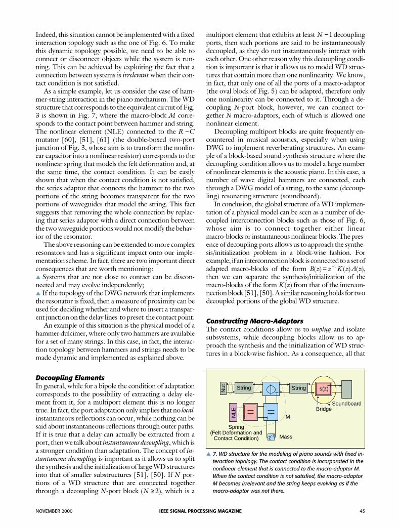
As a simple example, let us consider the case of ham-mer-string interaction in the piano mechanism. The WDstructure that corresponds to the equivalent circuit of Fig.3 is shown in Fig. 7, where the macro-block M corre-sponds to the contact point between hammer and string.The nonlinear element (NLE) connected to the R C−mutator [60], [51], [61] (the double-boxed two-portjunction of Fig. 3, whose aim is to transform the nonlin-ear capacitor into a nonlinear resistor) corresponds to thenonlinear spring that models the felt deformation and, atthe same time, the contact condition. It can be easilyshown that when the contact condition is not satisfied,the series adaptor that connects the hammer to the twoportions of the string becomes transparent for the twoportions of waveguides that model the string. This factsuggests that removing the whole connection by replac-ing that series adaptor with a direct connection betweenthe two waveguide portions would not modify the behav-ior of the resonator.
The above reasoning can be extended to more complexresonators and has a significant impact onto our imple-mentation scheme. In fact, there are two important directconsequences that are worth mentioning:▲ Systems that are not close to contact can be discon-nected and may evolve independently;▲ If the topology of the DWG network that implementsthe resonator is fixed, then a measure of proximity can beused for deciding whether and where to insert a transpar-ent junction on the delay lines to preset the contact point.
An example of this situation is the physical model of ahammer dulcimer, where only two hammers are availablefor a set of many strings. In this case, in fact, the interac-tion topology between hammers and strings needs to bemade dynamic and implemented as explained above.
Decoupling ElementsIn general, while for a bipole the condition of adaptationcorresponds to the possibility of extracting a delay ele-ment from it, for a multiport element this is no longertrue. In fact, the port adaptation only implies that no localinstantaneous reflections can occur, while nothing can besaid about instantaneous reflections through outer paths.If it is true that a delay can actually be extracted from aport, then we talk about instantaneous decoupling, which isa stronger condition than adaptation. The concept of in-stantaneous decoupling is important as it allows us to splitthe synthesis and the initialization of large WD structuresinto that of smaller substructures [51], [50]. If N por-tions of a WD structure that are connected togetherthrough a decoupling N-port block ( )N ≥2 , which is a
multiport element that exhibits at least N −1 decouplingports, then such portions are said to be instantaneouslydecoupled, as they do not instantaneously interact witheach other. One other reason why this decoupling condi-tion is important is that it allows us to model WD struc-tures that contain more than one nonlinearity. We know,in fact, that only one of all the ports of a macro-adaptor(the oval block of Fig. 5) can be adapted, therefore onlyone nonlinearity can be connected to it. Through a de-coupling N-port block, however, we can connect to-gether N macro-adaptors, each of which is allowed onenonlinear element.
Decoupling multiport blocks are quite frequently en-countered in musical acoustics, especially when usingDWG to implement reverberating structures. An exam-ple of a block-based sound synthesis structure where thedecoupling condition allows us to model a large numberof nonlinear elements is the acoustic piano. In this case, anumber of wave digital hammers are connected, eachthrough a DWG model of a string, to the same (decoup-ling) resonating structure (soundboard).
In conclusion, the global structure of a WD implemen-tation of a physical model can be seen as a number of de-coupled interconnection blocks such as those of Fig. 6,whose aim is to connect together either linearmacro-blocks or instantaneous nonlinear blocks. The pres-ence of decoupling ports allows us to approach the synthe-sis/initialization problem in a block-wise fashion. Forexample, if an interconnection block is connected to a set ofadapted macro-blocks of the form B z z K z A z( ) ( ) ( )= −1 ,then we can separate the synthesis/initialization of themacro-blocks of the form K z( ) from that of the intercon-nection block [51], [50]. A similar reasoning holds for twodecoupled portions of the global WD structure.
Constructing Macro-AdaptorsThe contact conditions allow us to unplug and isolatesubsystems, while decoupling blocks allow us to ap-proach the synthesis and the initialization of WD struc-tures in a block-wise fashion. As a consequence, all that
NOVEMBER 2000 IEEE SIGNAL PROCESSING MAGAZINE 45
Nut String
Spring(Felt Deformation and
Contact Condition)
SoundboardBridge
String
M
Massz-1
s( )z
NLE
▲ 7. WD structure for the modeling of piano sounds with fixed in-teraction topology. The contact condition is incorporated in thenonlinear element that is connected to the macro-adaptor M.When the contact condition is not satisfied, the macro-adaptorM becomes irrelevant and the string keeps evolving as if themacro-adaptor was not there.

is left to discuss is the construction and the initializationof a macro-adaptor.
An N-port macro-adaptor can be automatically builtthrough a tableau-based approach, specifically designedfor WD structures [51], [50]. Its description, in fact, canbe given in the form
S C 0( ) ( )z z T= ,
where S( )z is a 2N N× tableau matrix [3], 0 is a vectorwith N zero elements, and C( ) [ ]z A A B BN N
T= ⋅⋅⋅ ⋅⋅⋅1 1 isthe vector of digital waves. A generic macro-adaptor canbe thought of as a network of elementary (parallel or se-ries) three-port adaptors with memory that belong to apredefined collection. This allows us to construct S( )z by“pasting” a number of predefined 6 3× matrices into alarger sparse matrix. This matrix equation can be quiteeasily rearranged and inverted to obtain a state-updateequation, or else it can be solved iteratively using some ef-ficient numerical method for sparse matrix equations.
As our macro-adaptors are not memoryless, they needto be properly initialized, which is a critical operation forWD models of mechanical systems as it usually affects themutual position and contact conditions of mechanical ele-ments. The determination of the state update equation canbe seen as a direct form of the synthesis problem, as outputsignals are computed from input signals and memory con-tent. Initialization, on the other hand, can be seen as an in-verse problem, as memory content must be derived fromoutput and input signals. As the nonlinearity is “lumped,”this operation can be quite easily performed throughnonlinearity inversion and matrix inversion.
Making the Structure Time VaryingChanging any model parameters in a WD structure usuallyaffects all the other parameters as they are bound to satisfyglobal adaptation conditions. Temporal variations of thenonlinearities are easily implemented by employing specialWD two-port elements that are able to perform a variety oftransformations on the nonlinear characteristics (nonho-mogeneous scaling, rotation, etc.). Temporal variations ofRTFs, on the other hand, are implemented through aglobal recomputation of all model parameters on the be-half of a process that works in parallel with the simulator[51], [50]. This operation requires the remapping of thenonlinearities as well. This parameter update, however, isnot computationally intensive as it is performed at a ratethat is normally only a fraction of the signal rate (e.g., 100times slower). It is important to remember, however, thatabrupt parameter changes must be carefully dealt with notto affect the global energy in an uncontrollable fashion.
Automatic ImplementationSome methods are already available for synthesizing lin-ear macro-blocks [63]; therefore the automatic synthesisprocedure is based on the assumption that such elementsare already available in the form of a collection of pre-
synthesized structures. In its current state, the system thatwe developed is able to automatically compile the sourcecode that implements a WD structure based on standardWDF adaptors and new dynamic adaptors chosen from areasonably wide collection [51], [50]. The informationthat the system starts from is a semantic description of thenetwork of interactions between all such elements.
Currently, the family of blocks includes WD mutators[60] and other types of adaptors developed for modelingtypical nonlinear elements of the classical nonlinear cir-cuit theory (both resistive and reactive). The available lin-ear macro-blocks belong to the family of the DWGs [63],while the nonlinear maps are currently point wise de-scribed in the Kirchhoff domain and then automaticallyconverted in a piecewise-linear WD map. Typical lumpedWDF blocks are masses, springs, dampers, nonlinearities,ideal generators, and filters (especially allpass filters, forthe fine tuning of strings or acoustic tubes or to accountfor the dispersive propagation in some enharmonic elasticstructures such as bells, low piano strings, etc.). Typicaldistributed-parameter blocks are simple DWG imple-mentation of strings and acoustic tubes, generalizedDWG that accounts for rigidity and losses in a distributedfashion, reverberators based on Toeplitz matrices, greenfunctions, and DWG models of 2-D and 3-D structuressuch as membranes and bells.
The parameters can be modified “on the fly” to makethe structure time varying. A parallel process deals with theproblem of recomputation of all WD parameters, depend-ing on their changes expressed in the Kirchhoff domain.
An Example of ApplicationOur approach to the construction of the SGL has beentested on a variety of applications of musical acoustics.Starting from an appropriate semantic description of thebuilding blocks and their topology of interconnection, weused our authoring tool to automatically generate C++source code for the implementation of a number of typicalacoustic musical instruments. The timbral classes imple-mented with this method are hammered strings (piano,electric piano), plucked strings (guitar), bowed strings (vi-olin), reed instruments (clarinet, oboe), jet-flow acoustictubes (flute, organ pipes), percussions, etc.
One of these examples, namely the grand piano, hasbeen developed with a two-fold goal in mind: to testour solution to the problem of the mechanical model-ing of a nontrivial acoustic instrument and to test ourapproach to the construction of a dynamic topology ofinterconnection.
The basic mechanism of hammer-string interaction isshown in Fig. 3, which corresponds to the block-basedWD model of Fig. 7. As we can see in Fig. 8, the trajecto-ries of the hammer and of the string at contact point andthe temporal evolution of the force that the hammer ex-erts on the string are very “physical” and realistic. In fact,the hammer tends to bounce back a bit more every time awave is reflected by the nut or the bridge and returns at
46 IEEE SIGNAL PROCESSING MAGAZINE NOVEMBER 2000

the contact point, causing the ripples in the force’s profile.This behavior turns out to have a very realistic impact onthe resulting sound. The plotted output corresponds tothe acoustic signal at the bridge.
The global implementation of the piano model hasbeen entirely built using a rather extended network ofWDF and DWG elements. The DWG model of eachstring includes stiffness [59] and losses [64]. The bridgeis modeled as a bandpass filter (the WD equivalent of anRLC filter) and is connected to a rather complexsoundboard model based on a DWG network. Thestring’s fine tuning is performed using all-pass filters. Alimited number of hammers are used dynamically to hit afull-scale resonator such as the one described above, witha dynamic management of the contact conditions. As forthe spatialization layer, in its current state, a limited num-ber of virtual pick-ups are scattered on the soundboardmodel and the vibrational signals are sent to apseudophysical reverberator based on a circulant feed-back delay network [57].
Indeed, the computational complexity of the resultingalgorithm in this case coincides with the complexity of theresonating structure, whose role in the characterization oftimbres is predominant. Some simpler implementations,however, already run real time on low-cost PC platforms.For example, the WD model of an electromechanical pi-ano (e.g., Wurlitzer or Fender-Rhodes) can easily runwith full polyphony (61 or 73 keys) on a Pentium III(350 MHz).
Sound Rendering Layer: An OverviewThe literature is rich with sound reverberation techniquesof practical usability [30], which range from simplecomb-and-allpass filters that model early reverberation,to more complex resonating structures based on feedbackdelay networks [57], [58], DWG structures [64], [63]and multidimensional WDF [40]. Solutions based onDWG structures have the advantage of exhibiting a closesimilarity with the resonating structures used for soundgeneration through physical modeling. In fact, they areoften implemented as a network of delay lines connectedthrough multiport junctions.
When the goal is not just to obtain plausible reverbera-tions, but to achieve audio-realistic rendering, more com-plex solutions need to be considered. Advanced renderingtechniques, in fact, are aimed at creating a sense of pres-ence by enabling a certain auditory comprehension of theproportions and the geometry of the surrounding space.
The sound rendering techniques that are available inthe literature [29] can be roughly classified into five fami-lies: finite element methods, image source methods,boundary element methods, path tracing, and beam trac-ing. Aside from the first class of methods, all such tech-niques are inspired by visual rendering solutions. Thereare some strong differences between light and sound radi-ation, however, which complicate the situation in the
acoustic case. First of all, sound wavelengths are muchlonger than light wavelengths. This does not allow us toignore the phenomena of diffraction. Other conse-quences of having longer wavelengths are that specularreflections become dominant over diffuse reflections andthat occlusions due to small objects have little impact onsound spatialization. A second significant difference isthat sound propagation is much slower than light propa-gation. In fact, reverberations are the result of differentpropagation delays in different paths. Another crucial dif-ference from visual rendering is that sound propagation iscoherent. In fact, when modeling sound propagation wemust carefully take the phase of acoustic waves into ac-count. Because of these differences, successful visual ren-dering technique could easily translate into unfeasiblesound rendering solutions.
Finite element methods consist of solving the wavepropagation equation over a predefined volumetricgrid. One interesting WDF-based solution within thiscategory was proposed by Rabenstein [56], [40], [41].These solutions produce very accurate results but theyrequire the modeling of the propagation on all thepoints of a dense grid that samples the spatialization vol-ume, which makes it quite demanding in terms of bothmemory and computations.
Image source methods [1], [9] are a first example ofmodeling of specular acoustic reflections in environments.They consist of computing specular reflection paths by“mirroring” the sound source over each surface of the envi-ronment. A line segment that connects a virtual (mirrored)source with the receiver is used to model a specular reflec-
NOVEMBER 2000 IEEE SIGNAL PROCESSING MAGAZINE 47
0
1
2
3
4
5
2 4 6 8 t ms[ ]
F N[ 0.1]�
y mms [ ]
y mmh [ ]
y [ ]mm
−3
−2
−1
0
1
2
0 20 40 60 80 t ms[ ]
▲ 8. Model simulation of an acoustic piano through a WD model.F is the force that the hammer applies to the string, y h is theposition of the hammer, and ys is the position of the string atthe contact point. Finally, y is the position of the string at thesoundbridge.

tion path. Higher order reflection paths can be obtainedthrough a recursive generation of virtual sources throughrepeated mirroring. Indeed, this approach is robust, but itcan only model specular reflections. Furthermore, its com-putational complexity increases exponentially with thenumber of reflections that we want to account for, whichmakes it feasible only for simple environments.
To approach the audio-realistic rendering problem inan object-based fashion, we need, once again, to invoke theparallelisms with classical visual rendering methods.Boundary element methods, path tracing, and beam trac-ing are all directly derived from visual rendering solutions.
Examples of boundary element methods that are ex-tensively used in computer graphics are the so-called radi-ant exchange methods [17], [32], which model diffusereflection of radiosity between surfaces. These techniquesrequire the computation of form factors to measure theradiosity exchanged between pairs of surfaces patches. Toobtain the radiosity of each surface patch of a given 3-Denvironment, it is necessary to simultaneously solve a setof transport equations.
Unfortunately, the success that this approach has hadin visual rendering is difficult to match in the acoustic ren-dering case [46], [69]. This is because transport equa-tions in acoustic modeling are expected to account for allthe above-mentioned differences between light andsound radiation. In particular, they have to account forphase. Furthermore, besides specular reflections, theymust consider paths of diffraction through extended formfactor computations. Finally, to obtain good renderingresults, the size of the surface patches must be muchsmaller than the acoustic wavelength and the solutionmust be computed for a number of frequencies, whichmakes the radiant exchange approach of little practical us-ability, especially for large 3-D environments.
Another class of image rendering techniques that has acounterpart in audio spatialization is ray tracing [31],[27], [73], [38]. Acoustic rays (paths) can be defined assmall portions of spherical acoustic waves of negligible ap-erture, and geometrical acoustics can be applied to describethe reflections of such rays on objects [43]. A simple imple-mentation of this approach for acoustic rendering can beobtained by ignoring the phenomenon of diffraction. Thiscorresponds to assuming that acoustic wavelengths of in-terest are negligible compared with the size of the objectsin the environment. In some applications where the fre-quencies that we care to spatialize are the higher ones, thismight be not a restrictive assumption. Another assump-tion that needs to be made is the mutual incoherence (i.e.,the absence of mutual interferences) between the waves as-sociated to different acoustic rays. This last one is a difficultcondition to guarantee in advance, but is generally verifiedwith good approximation.
Along the direction of the acoustic ray, the pressuredecreases with the square power of the distance. Whenthe acoustic ray hits an object, a reflection occurs in a waythat depends on the physical characteristics of the surface.
If we focus just on specular reflections, we need to ac-count for a filtering effect, due to the fact that the surfacematerial interacts with the incident wave in a fre-quency-dependent fashion. This filtering can be modeledby a transfer function of the form
K ZZ
= −+
coscos
,θθ
11
where θ is the angle of incidence of the acoustic ray and Zis the (frequency-dependent) characteristic impedance ofthe reflecting surface. When the surface is rigid andsmooth, Z → ∞ and K →1, providing a perfect reflectionregardless of the incidence angle.
Path tracing techniques [42] consist of determining allthe acoustic rays of interest between a sound source and alistening point (receiver). Rays are generated from thesource point and followed through the environment untilan appropriate set of significant rays is found to reach thelistening point [38].
Path tracing methods have the advantage of being sim-ple to implement, as only the interaction between raysand surfaces need to be computed. As a consequence, un-like finite element methods, the complexity depends lessthan linearly on the number of surfaces of the modeledenvironment. Furthermore, they can be devised and im-plemented in such as way as to model surface-ray interac-tions that are more complex than specular reflection. Infact, paths of diffuse reflection, diffraction, and refractioncan be sampled as well. By doing so, it is possible to modelany type of indirect reverberation and to accommodatearbitrarily shaped surfaces [18]. Conversely, path tracingtechniques require a strong sampling of the fifth-dimen-sional (5-D) parameter space that describes all possiblerays, which gives rise to approximations [45] and aliasingin the acoustic response of the environment. Approxima-tions are due to the limited number of paths that can bemodeled, while alias is due to the fact that there is noguarantee that some important acoustic ray will not bemissed in the sampling process. Furthermore, such meth-ods are difficult to implement when the auditory point isnot stationary, as changes in the location of the receiverwould require path retracing.
A very promising technique that overcomes, in part,these limitations is represented by beam tracing [29],which is the acoustic counterpart of the visual renderingtechnique described in [34]. Beam tracing methods are,in a way, a generalization of ray tracing techniques, asthey trace pyramidal bundles of rays throughout the envi-ronment. Roughly speaking, the approach starts with thesurface-based segmentation of the whole set of rays thatemanate from the sound source. This first step produces anumber of beams, each of which illuminates a differentsurface. Such beams are then clipped to remove theshadow region, which is then replaced by a properly con-structed transmission beam. A reflection beam can thenbe obtained through the creation of a virtual source bysimply mirroring the transmission beam over the surface.
48 IEEE SIGNAL PROCESSING MAGAZINE NOVEMBER 2000

The process is repeated for the reflected beam which, inturn, intersects some other surfaces. The main advantageof beam tracing over path tracing is that it exploits spatialcoherence since, with a single beam, we can model an infi-nite number of ray-surface intersections. This overcomesthe above-mentioned problems of approximation andaliasing that arise from a sampling of the 5-D parameterspace that describes the rays. On the other hand, beamtracing methods are more difficult to implement than raytracing techniques. In fact, determining intersection andclipping beams can become rather complicated from ageometric standpoint. Even more complex can be themodeling of refractions or reflections off curved surfaces.
An interesting characteristic of this approach [29] isthe possibility of computing the topology of interactionbetween sources and surfaces through off-line preanalysiscalled beam tracing. This topology is described by a graphcalled a beam tree. By doing so, the rendering processconsists of performing a lookup search for the beams ofthe beam tree that contain the moving receiver.
All the sound rendering solutions that have beenbriefly discussed in this section exhibit a number of ad-vantages and disadvantages. When the goal is to obtainplausible reverberations rather than audio-realistic soundrendering, DWG techniques can be an interesting solu-tion. In fact, they operate in a fully object-based fashionand are very similar in spirit to the sound synthesis ap-proach proposed in this article for the SGL. The soundrendering techniques based on finite elements represent agood solution when we are interested in the modeling ofthe spatialization of low-frequency sounds, but they arenot object based. Boundary element methods are alsobest suited for a realistic spatialization of low-frequencysounds, but their complexity is very high. When dealingwith simple environments (typically a rectangular room),image source methods are probably the best solution, al-though they are limited to the modeling of specular re-flections only. Depending on our expectations on thespatialization accuracy, path tracing and beam tracing ap-pear to be very promising sound-rendering techniques.Path tracing is an excellent approach for modeling higherorder reflections, although it is difficult to employ withdynamically moving auditory points. Although beamtracing appears to be more complex to implement, it en-ables the precomputation of the topology of interactionbetween surfaces and sources (beam tree). Both tracingsolutions are also very close in spirit to the object-basedlayered organization of audiovisual 3-D environments, aspresented in this article. Furthermore, we can outline anumber of similarities between the object-based soundsynthesis technique that we proposed for the SGL andsuch spatialization techniques for the SRL. In fact, inboth cases, the construction and the managing of the to-pology of interactions is the most challenging and com-plex tasks to perform.
ConclusionsIn this article we illustrated our approach to the construc-tion of an object-based environment for sound genera-tion, whose objects are individually synthesized andinteract with each other through the modeling of theirpotential interaction topology. In particular, we showedhow this interaction topology can be implemented insuch a way to avoid problems of computability and topreserve the physical properties of the reference acousticstructure such as passivity and losslessness. We then illus-trated our strategy to make this interconnection dynamicand time varying. We also discussed how we envision anobject-based environment that integrates geometric, ra-diometric, and intrinsic/extrinsic acoustic properties.
The proposed approach has proven effective for theautomatic and modular synthesis of a wide class of physi-cal structures encountered in musical acoustics. In fact,the wave tableau approach we implemented makes theconstruction and the implementation of the interactiontopology simple and systematic. In its current state, theimplementation of the described synthesis system is ableto assemble the synthesis structure from a syntactic de-scription of its objects and their interaction topology,providing the user with a first CAD approach to the con-struction of an interactive sound environment.
We finally gave a brief overview on the available soundrendering methods and their potential of integrationwithin a layered representation of audiovisual 3-D envi-ronments. The resulting scenario is challenging andpromising, as new forms of interaction between users andacoustically responsive virtual environments will be pos-sible, in which sounds will be generated through themodeling of the physical interaction between objects andwill be correctly spatialized and auralized.
It is important to mention that a first example of vir-tual audio reality system has already been developedwithin the EC-sponsored DIVA project [36], [62], [47].This work already constitutes a significant step forward inthe direction of audiovisual integration, althoughfull-scale interactivity and object-based solutions are notyet a reality in the achieved results. We are currentlyworking on a full-scale implementation of the layeredstructure for audiovisual environments as presented inthis article. In particular, we are focusing on the SRL andits interactions with the SGL.
One concluding remark on future directions of researchis that there is a strong need of understanding what kind ofapproximations can be made on the synthesis-renderingstructure in both SGL and SRL without significantly im-pacting on human perception of sound quality. As weknow, there is virtually no limit in the level of detail thatcan be used in modeling physical reality. This is true forboth spatialization and sound synthesis. A better under-standing of the link between perceptual redundancy andphysical accuracy of the models would thus help us sim-plify the implementation of audiovisual environments.
NOVEMBER 2000 IEEE SIGNAL PROCESSING MAGAZINE 49

AcknowledgmentsWe wish to thank Dr. Enrico Bianchi of Phoenix ToolsLtd. for the fruitful discussions on problems of photo-realistic and audiorealistic rendering.
Federico Pedersini was born in Brescia, Italy, in 1965. He re-ceived the “laurea” degree (summa cum laude) in electricalengineering in 1991 and the doctoral degree in electricalengineering and communications in 1994, both from thePolitecnico di Milano, Milan, Italy. He spent one year atthe Intitut fur Theoretische Nachrichtentechnik of theUniversity of Hannover, Germany, working on cameracalibration for 3-D reconstruction systems and accuratemodeling of camera imaging process. He is currentlywith the Politecnico di Milano, where he is doing researchon image processing for 3-D measurement, reconstruc-tion, and image synthesis.
Augusto Sarti was born in Rovigo, Italy, in 1963. He re-ceived the “laurea” degree (summa cum laude) in electri-cal engineering in 1988 and a doctoral degree in electricalengineering and information sciences in 1993, both fromthe University of Padova, Padua, Italy. He worked forone year for the Italian National Research Council, doingresearch on digital radio systems. He then spent two yearsdoing research on nonlinear system theory at the Univer-sity of California, Berkeley. He is currently an AssistantProfessor at the Politecnico di Milano, Milan, Italy, andhis research interests are in digital signal processing and,in particular, in video coding, image analysis for 3-Dscene reconstruction, and audio processing and synthesis.
Stefano Tubaro was born in Novara, Italy, in 1957. Hecompleted his studies in electrical engineering in 1982.He joined the Politecnico di Milano, Dipartimento diElettronica e Informazione in 1984, doing research onvoice and image coding. In 1986 he joined the CSTS(Study Center for Space Telecommunications) of theCNR (National Research Council). Since 1991 he hasbeen an Associate Professor of Electrical Communica-tions at the Politecnico di Milano. His current researchinterests focus on digital image processing and, in partic-ular, on video sequence coding at low bit-rate throughmotion estimation and image segmentation. He alsoworks on stereovision for 3-D scene reconstruction ap-plied to remote manipulation, autonomous vehicle guid-ance, and telepresence.
References[1] J. Allen and D. Berkley, “Image method for efficiently simulating
small-room acoustics,” J. Acoustical Soc. Amer., vol. 65, no. 4, pp. 912-915,Apr. 1979.
[2] P. Beardsley, P. Torr, and A. Zisserman, “3-D model acquisition from ex-tended image sequences,” in Proc. ECCV ‘96, Cambridge, UK, Apr. 14-18,1996, vol. 2, pp. 683-695.
[3] V. Belevitch, Classical Network Theory. San Francisco, CA: Holden Day,1968.
[4] A. Blake and A. Zisserman, Visual Reconstruction. Cambridge, MA: MITPress, 1987.
[5] G. Borin, G. De Poli, and A. Sarti, “A modular approach to excitator-reso-nator interaction in physical models synthesis,” in Proc. Int. Computer MusicConf., Columbus, OH, Nov. 1990, pp. 46-50.
[6] G. Borin, G. De Poli, and A. Sarti, “Sound synthesis by dynamic systemsinteraction,” in Readings in Computer-Generated Music, D. Baggi, Ed. LosAlamitos, CA: IEEE Computer Society Press, 1992, pp. 139-160.
[7] G. Borin, G. De Poli, and A. Sarti, “Algorithms and structures for synthesisusing physical models,” Computer Music J., vol. 19, no. 4, pp. 30-42, 1992.
[8] G. Borin, G. De Poli, and A. Sarti, “Musical signal synthesis,” in MusicalSignal Processing, C. Roads, S. Pope, A. Piccialli, and G. DePoli, Eds. Lisse,Netherlands: Swets and Zeitlinger, 1996, pp. 5-30.
[9] J. Borish, “Extension of the image model to arbitrary polyhedra,” J. Acoust.Soc. Amer., vol. 75, no. 6, pp. 1827-1836, June 1984.
[10] K. Brandenburg, “Perceptual coding of high quality digital audio,” in Ap-plications of Digital Signal Processing to Audio and Acoustics, M. Kahrs and K.Brandenburg, Eds. Norwell, MA: Kluwer, 1998, pp. 85-131.
[11] L.O. Chua, “Synthesis of new nonlinear network elements,” Proc. IEEE,vol. 56, pp. 1325-1340, Aug. 1968.
[12] L.O. Chua, Introduction to Nonlinear Network Theory. New York:McGraw-Hill, 1969.
[13] L.O. Chua, “Memristor—The missing circuit element,” IEEE Trans. Cir-cuit Theory, vol. CT-18, pp. 507-519, Sept. 1971.
[14] L.O. Chua, “Device modeling via basic nonlinear circuit elements,” IEEETrans. Circuits Syst., vol. CAS-27, pp. 1014-1044, Nov. 1980.
[15] L.O. Chua, “Dynamic nonlinear networks: State-of-the-art,” IEEE Trans.Circuits Syst., vol. CAS-27, pp. 1059-1087, Nov. 1980.
[16] L.O. Chua, “Nonlinear circuits,” IEEE Trans. Circuits Syst., vol. CAS-31,pp. 69-87, Jan. 1984.
[17] M.F. Cohen and J.R. Wallace, Radiosity and Realistic Image Synthesis.Reading, MA: Academic, 1993.
[18] R.L. Cook, T. Porter, and L. Carpenter. “Distributed ray tracing,” in Proc.SIGGRAPH’84, vol. 18, pp. 137-146.
[19] N. Dadoun, D.G. Kirkpatrick, and J.P. Walsh. “The geometry of beamtracing,” in Proc. Symp. Computational Geometry, Baltimore, MD, June,1985, pp. 55-71.
[20] G. De Poli, “A tutorial on digital sound synthesis techniques,” in The MusicMachine, C. Roads, Ed. Cambridge, MA: MIT Press, 1992, pp. 429-447.
[21] T. Felderhoff, “Simulation of nonlinear circuits with period doubling andchaotic behavior by wave digital principles,” IEEE Trans. Circuits Syst. I,vol. CAS-41, pp. 485-491, July 1994.
[22] T. Felderhoff, “A new wave description for nonlinear elements,” IEEE Int.Symp. Circuits and Systems, Atlanta, GA, May 12-15, 1996, pp. 221-224.
[23] A. Fettweis, “Wave digital filters: Theory and practice,” Proc. IEEE, vol.74, pp. 327-270, Feb. 1986.
[24] A. Fettweis, “Some principles of designing digital filters imitating classicalfilter structures,” IEEE Trans. Circuit Theory, vol. CT-18, pp. 314-316,Mar. 1971.
[25] A. Fettweis, “Pseudopassivity, sensitivity, and stability of wave digital fil-ters,” IEEE Trans. Circuit Theory, vol. CT-19, pp. 668-673, Nov. 1972.
[26] A. Fettweis and K.Meerkötter, “On adaptors for wave digital filters,”IEEE Trans. Acoustic, Speech, Signal Processing, vol. ASSP-23, pp. 516-525,Dec. 1975.
[27] J.D. Foley, A. van Dam, S.K. Feiner, and J.F. Hughes, Computer Graphics:Principles and Practice. 2nd ed. in C, Reading, MA: Addison-Wesley, 1996.
[28] F. Fontana and D. Rocchesso, “Physical modeling of membranes for per-cussion instruments,” Acustica - Acta Acustica, vol. 84, no. 3, pp. 529-542,May-June 1998.
50 IEEE SIGNAL PROCESSING MAGAZINE NOVEMBER 2000

[29] T. Funkhouser, I. Carlbom, G. Elko, G. Pingali, M. Sondhi, and J. West,“A beam tracing approach to acoustic modeling for interactive virtual envi-ronments,” in Proc. SIGGRAPH’98, pp. 21-32.
[30] W. Gardner, “Reverberation algorithms,” in Applications of Digital SignalProcessing to Audio and Acoustics, M. Kahrs and K. Brandenburg, Eds. Nor-well, MA: Kluwer, 1998, pp. 85-131.
[31] A.S. Glassner, An Introduction to Ray Tracing. New York: Academic,1989.
[32] C.M. Goral, K.E. Torrance, D.P. Greenberg, and B. Battaile, “Modelingthe interaction of light between diffuse surfaces.” in Proc. SIGGRAPH’84,vol. 18, pp. 213-222.
[33] R. Hall, Illumination and Color in Computer-Generated Imaging. NewYork: Springer-Verlag, 1989.
[34] P. Heckbert and P. Hanrahan, “Beam tracing polygonal objects,” in Proc.SIGGRAPH’84,, vol. 18, pp. 119-127.
[35] M. Hodgson, “Evidence of diffuse surface reflections in rooms,” J. Acoust.Soc. Amer., vol. 89, pp. 765-771, 1991.
[36] J. Huopaniemi, L. Savioja, and T. Takala, “DIVA virtual audio reality sys-tem,” in Proc. Int. Conf. Auditory Display, (ICAD’96), Palo Alto, CA, Nov.4-6, 1996, pp. 111-116.
[37] C.B. Jones, “A new approach to the ‘hidden line’ problem,” Computer J.,vol. 14, no. 3, pp. 232-237, Aug. 1971.
[38] J.T. Kajiya, “The rendering equation,” in Proc. SIGGRAPH’86, vol. 20,pp. 143-150.
[39] T. Kanade, P. Rander, and P.J. Narayanan, “Virtualized reality: Con-structing virtual worlds from real scenes.” IEEE Multimedia, vol. 4, pp.34-47, Jan.-Mar. 1997.
[40] H. Krauß and R. Rabenstein, “Application of multidimensional wave dig-ital filters to boundary value problems,” IEEE Signal Processing Lett., vol. 2,pp. 138-140, July 1995.
[41] H. Krauß, R. Rabenstein, and M. Gerken, “Simulation of wave propaga-tion by multidimensional digital filters,” J. Simulation Practice Theory, vol. 4,pp. 361-382, 1996.
[42] U.R. Krockstadt, “Calculating the acoustical room response by the use ofa ray tracing technique,” J. Sound Vibr., no. 8, vol. 18, 1968.
[43] H. Kuttruff, Room Acoustics, 3rd ed. New York: Elsevier Science, 1991.
[44] H. Kuttruff, “A simple iteration scheme for the computation of decayconstants in enclosures with diffusely reflecting boundaries,” J. Acoustic Soc.Amer., vol. 98, no. 1, pp. 288-293, July 1995.
[45] H. Lehnert, “Systematic errors of the ray-tracing algorithm,” J. AppliedAcoustics, vol. 38, nos. 2-4, pp. 207-221, 1993.
[46] T. Lewers, “A combined beam tracing and radiant exchange computermodel of room acoustics,” J. Applied Acoustics, vol. 38, nos. 2-4, pp.161-178, 1993.
[47] T. Lokki, L. Savioja, and J. Hiipakka, “Immersive 3-D sound reproduc-tion in virtual room,” in Proc. AES 16th Int. Conf. Spatial Sound Reproduc-tion, Rovaniemi, Finland, Apr. 10-12, 1999, pp. 172-177.
[48] D.C. Massie, “Wavetable sampling synthesis,” in Applications of DigitalSignal Processing to Audio and Acoustics, M. Kahrs and K. Brandenburg, Eds.Norwell, MA: Kluwer, 1998, pp. 85-131.
[49] K. Meerkötter and R. Scholtz. “Digital simulation of nonlinear circuits bywave digital filter principles,” in Proc. IEEE Int. Symp. Circuits and Systems,Portland, OR, May 8-11, 1989, vol. 1, pp. 720-723.
[50] F. Pedersini, A. Sarti, and S. Tubaro, “Block-wise physical model synthesisfor musical acoustics,” IEE Electron. Lett., vol. 35, no. 17, pp. 1418-1419,Aug. 1999.
[51] F. Pedersini, A. Sarti, S. Tubaro, and R. Zattoni, “Toward the automaticsynthesis of nonlinear wave digital models for musical acoustics,” in Proc.IX Euro. Signal Processing Conf., Sept. 8-11, 1998, Rhodes, Greece, vol. IV,pp. 2361-2364.
[52] F. Pedersini, P. Pigazzini, A. Sarti, and S. Tubaro, “3-D area matchingwith arbitrary multiview geometry,” in Proc. EURASIP Signal Processing:Image Communications, vol. 14, nos. 1-2, pp. 71-94, 1998.
[53] F. Pedersini, A. Sarti, and S. Tubaro, “multicamera systems: calibration andapplications,” IEEE Signal Processing Mag., vol. 16, pp. 55-65, May 1999.
[54] F. Pedersini, A. Sarti, and S. Tubaro, “Visible surface reconstruction withaccurate localization of object boundaries,” IEEE Trans. Circuits Syst. VideoTechnol., vol. 10, pp. 278-291, Mar. 2000.
[55] F. Pedersini, P. Pigazzini, A. Sarti, and S. Tubaro, “Multicamera motionestimation for high-accuracy 3-D reconstruction.” EURASIP Signal Pro-cessing, vol. 80, no. 1, pp. 1-21, Jan. 2000.
[56] R. Rabenstein and H. Krauß: “Discrete simulation of uniform transmis-sion lines by multidimensional digital filters.” Int. J. Numer. Model., vol. 9,pp. 271-294, 1996.
[57] D. Rocchesso J and O. Smith: “Circulant and elliptic feedback delay net-works for artificial reverberation,” IEEE Trans. Speech Audio Processing, vol.5, no. 1, pp. 51-63, Jan. 1997.
[58] D. Rocchesso, “Maximally diffusive yet efficient feedback delay networksfor artificial reverberation,” IEEE Signal Processing Lett., vol. 4, no. 9, pp.252-255, Sept. 1997.
[59] D. Rocchesso and F. Scalcon, “Bandwidth of perceived inharmonicity forphysical modeling of dispersive strings,” IEEE Trans. Speech Audio Pro-cessing, vol. 7, pp. 597-601, Sept. 1999.
[60] A. Sarti and G. De Poli, “Generalized adaptors with memory for nonlinearwave digital structures.” in Proc. VIII European Signal Processing Conf.,Trieste, Italy, 1996, vol. 3, pp. 1773-1776.
[61] A. Sarti and G. De Poli, “Toward nonlinear wave digital filters,” IEEETrans. Signal Processing, vol. 47, pp. 1654-1668, June 1999.
[62] L. Savioja, J. Huopaniemi, T. Lokki, and R. Väänänen, “Virtual environ-ment simulation advances in the DIVA project,” in Proc. Int. Conf. AuditoryDisplay (ICAD’97), Palo Alto, CA, Nov. 3-5, 1997, pp. 43-46.
[63] J.O. Smith, “Acoustic modeling using digital waveguides,” in Musical Sig-nal Processing, C. Roads, S.T. Pope, A. Piccialli, and G. DePoli, Eds. Lisse,The Netherlands: Swets and Zeitlinger, 1997, pp. 221-263.
[64] J.O. Smith, “Principles of digital waveguide models of musical instru-ments,” in Applications of Digital Signal Processing to Audio and Acoustics, M.Kahrs and K. Brandenburg, Eds. Norwell, MA: Kluwer, 1998, pp. 417-466.
[65] S.J. Teller and C.H. Séquin, “Visibility preprocessing for interactivewalkthroughs,” in Proc. SIGGRAPH’91, vol. 25, pp. 61-69.
[66] D. Terzopoulos and A. Witkin, “Physically based models with rigid anddeformable components,” IEEE Computer Graphics and Applications, vol. 8,no. 6, pp. 41-51, 1988.
[67] D. Terzopoulos and D. Thalmann, Computer Animation and Simulation.New York: Springer-Verlag, 1995.
[68] http://www.3-Dscanners.com/
[69] N. Tsingos and J. Gascuel, “A general model for simulation of roomacoustics based on hierarchical radiosity, technical sketches,” in SIGGRAPH97 Visual Proc., 1997.
[70] Väänänen, V. Välimäki, J. Huopaniemi, and M. Karjalainen, “Efficientand parametric reverberator for room acoustics modeling,” in Proc. Int.Computer Music Conf. (ICMC’97), Thessaloniki, Greece, Sept. 25-30, 1997,pp. 200-203.
[71] S.A. Van Duyne, J.R. Pierce, and J.O. Smith, “Traveling-wave implemen-tation of a lossless mode-coupling filter and the wave digital hammer,” inProc. 1994 Intl. Computer Music Conf., 1994, pp. 411-418.
[72] L. Van Gool and A. Zisserman, “Automatic 3-D model building fromvideo sequences,” Euro. Trans. Telecommun., vol. 8, no. 4, pp. 369-378,July-Aug. 1997.
[73] T. Whitted, “An improved illumination model for shaded display,”Commun. ACM, vol. 23, no. 6, pp. 343-349, June 1980.
NOVEMBER 2000 IEEE SIGNAL PROCESSING MAGAZINE 51