using response function concepts to model groundwater ...– offset wenner (5...
TRANSCRIPT

Surface geophysics
ER Method

Geophysics
• Theory & application• Equipment• Field procedures – good practice and reporting• Guidelines for Offset Wenner method• Field sheets• Need for calibration against other methods• Trouble shooting• Case study

ER Principles
• Apparent resistivity of ground• Measured using an array of electrodes
– Two current– Two potential
• Effective depth of measurement depends on electrode spacing– Soundings (fixed centreline)– Profiles (fixed spacing)
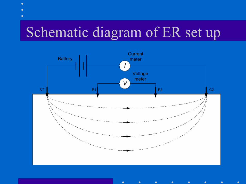
Schematic diagram of ER set up
I
V
BatteryCurrentmeter
Voltagemeter
C1 P1 P2 C2

Sounding & ProfilingSounding aims to detect vertical changes
Profiling aims to detect lateral changes

Resistance
• Resistance = Voltage/Current
R = V/I
I
V
BatteryCurrentmeter
Voltagemeter
C1 P1 P2 C2

Resistivity
• Measured resistance depends on– Array set up– Electrical resistivity (intrinsic property)
• Resistivity = Geometric factor for array * R– E.g. for the Wenner array
where a = electrode spacing
aRa πρ 2=

Array configurations
• Standard arrays– Wenner (equal spacing between all electrodes)– Schlumberger (voltage measurement over a
smalling spacing)• Non-standard
– Offset Wenner (5 electrodes/spacing)– Multi-electrode systems

Wenner vs Schlumberger•Requires less instrument sensitivity•Reduction of data marginally easier•Favoured in the US
I
V
BatteryCurrentmeter
Voltagemeter
C1 P1 P2 C2
•Faster because only outer electrodes need to be moved•More sensitive in distinguishing lateral from vertical variations•Favoured in Europe
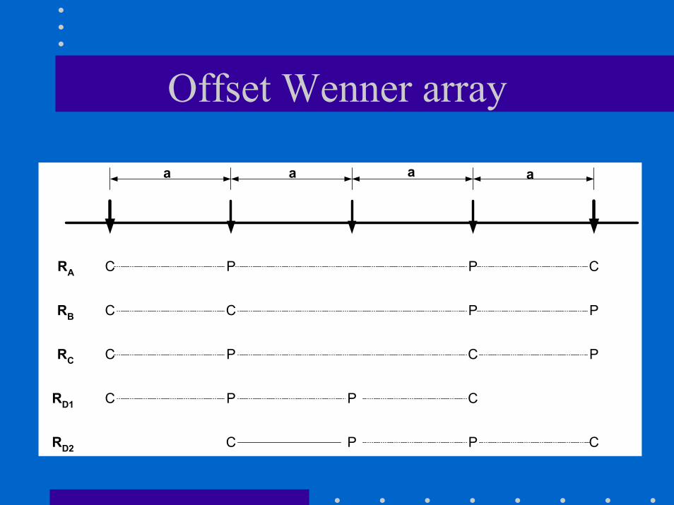
Offset Wenner array
RA
RB
RC
RD1
RD2
a a a a
C
C
C
C
P P
C
P
P
C
P
C
P C
P P C
C
P
P

Offset Wenner measurements
• 5 electrode positions to measure
RA
RB
RC
RD1
RD2
a a a a
C
C
C
C
P P
C
P
P
C
P
C
P C
P P C
C
P
P
– Two (offset) Wenner resistances (RA and RB)
• reduce effects of lateral underground resistivity variations
– 3 additional resistances (RC, RD1 and RD2)
• Allow calculation of observation error
• RA = RB + RC

Equipment
• ABEM SAS 300 Terrameter• BGS 256 multi-electrode system
– 2 Multi-core cables– 21 electrodes– Switch box
• Total cable spread 512 m• NB: Solomon Islands, Vanuatu, Fiji
(MRD), SOPAC have this equipment

Guidelines for method
• Best used in horizontal layered situation• To detect coastal saline water, soundings should
ideally be parallel to the coast• Desirable to use full cable spread where possible• Resistance measurements should begin with
smallest electrode spacing• Observations and observation errors should be
recorded at each setting• Apparent resistivities should be calculated and
plotted in the field

Field procedures
• Preparation• Location• Setting up• Taking measurements• Field Calculations
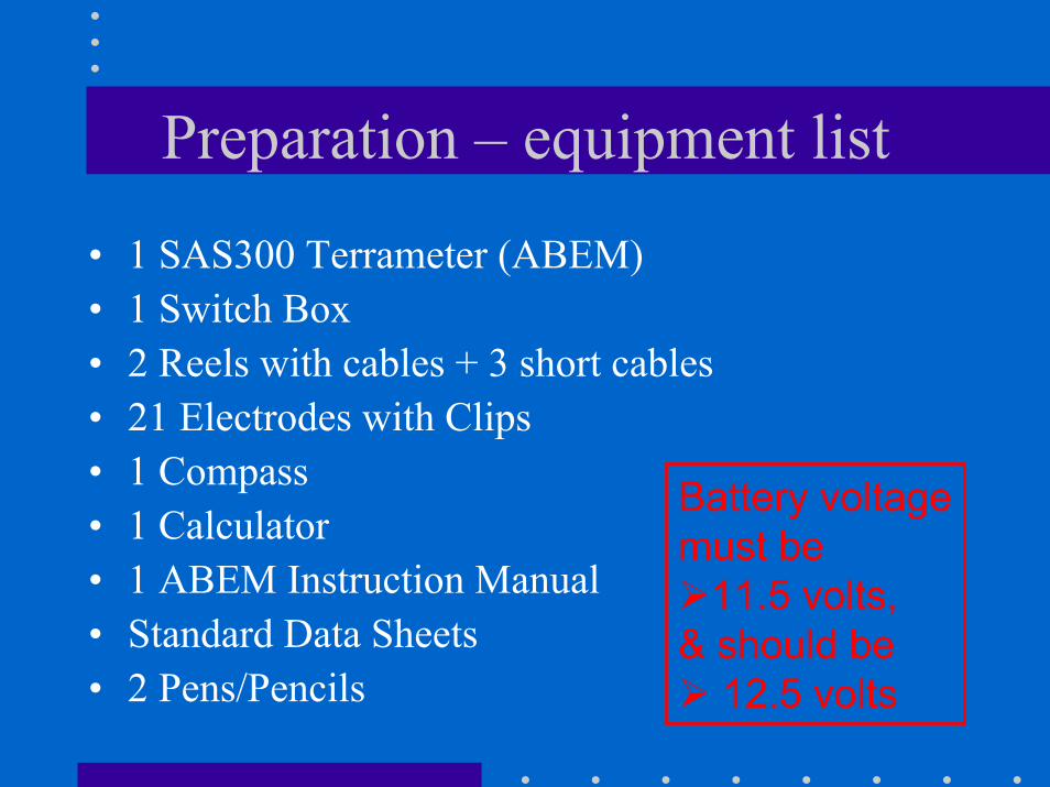
Preparation – equipment list
• 1 SAS300 Terrameter (ABEM)• 1 Switch Box• 2 Reels with cables + 3 short cables • 21 Electrodes with Clips• 1 Compass• 1 Calculator• 1 ABEM Instruction Manual• Standard Data Sheets• 2 Pens/Pencils
Battery voltage must be
11.5 volts,& should be
12.5 volts

Location - consider
• Location of proposed borehole/s.• Line requires a reasonably straight site.• Line should avoid large obstacles or metallic
objects.• If less than 500 metres from the shoreline make
the line run approximately parallel to the shore.• Avoid cables running onto slopes and over hills.

Location - continued
• Avoid running the cable along formed roads• If cable lines cross roadways, either stop
traffic or raise the cable to allow traffic to pass.
• Take weather conditions into consideration:Do not make measurements in the rainAvoid thunderstorms and lightning
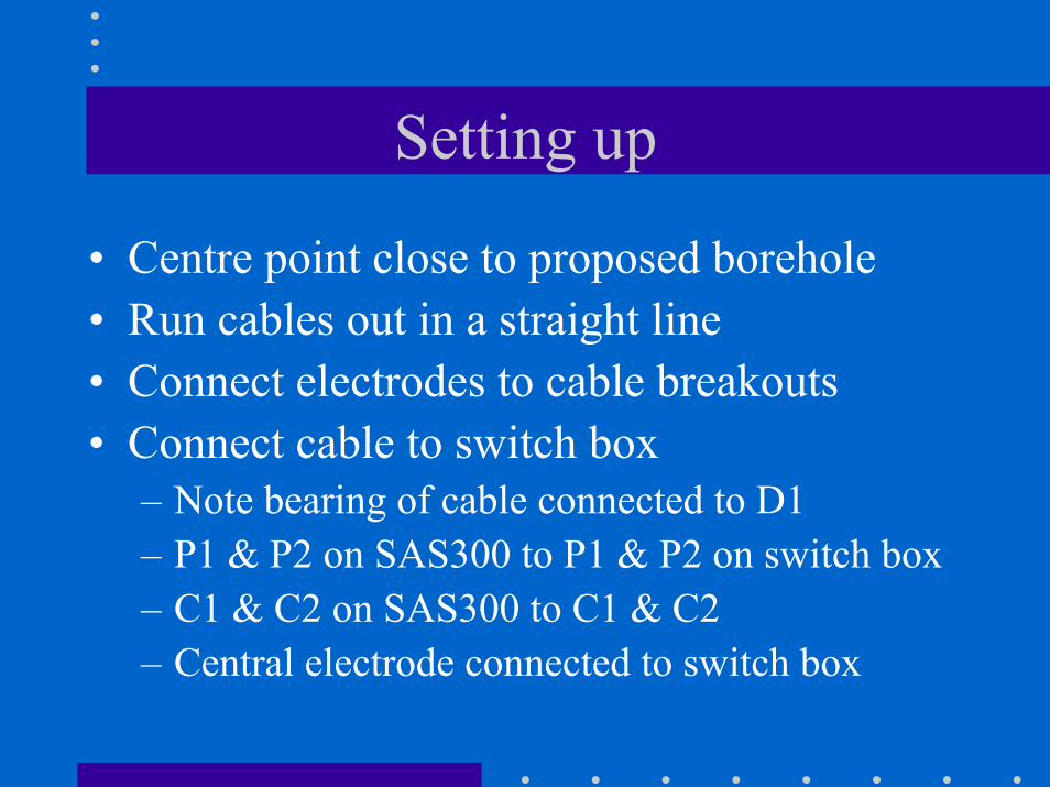
Setting up
• Centre point close to proposed borehole• Run cables out in a straight line• Connect electrodes to cable breakouts• Connect cable to switch box
– Note bearing of cable connected to D1– P1 & P2 on SAS300 to P1 & P2 on switch box– C1 & C2 on SAS300 to C1 & C2– Central electrode connected to switch box

Taking measurements
1. Fill out site details on standard data sheet.2. Check the battery to ensure it is still charged,
• > 11.5 volts (use battery check on the SAS300)
3. Set PC switch towards the BGS label.• Start with a current setting of 20mA. Always use
maximum current obtainable and decrease as required.
4. Set the resistivity range either to 1 ohm or 100 ohms

Taking measurements (cont.)
5. Take measurements for A, C, D1, D2 and B at settings 1 to 9.• If an error code is displayed refer to the error code
sheet. (e.g. error message "1" indicates that a current electrode is disconnected)
6. Record the measured resistance• make sure consistent readings are obtained• Note the units recorder e.g. mohms, ohms or kohms• Use the standard data sheet• Measure the direction of the cable line using a
compass and record on the data sheet.

Field calculations
• Field calculation of the Wenner Resistivity should be carried out using the field sheet.
• Calculations involve– finding the average of measurements RD1 and
RD2– multiplying by 2πa (a = spacing)
• Plot values on log-log graph paper.• Draw a curve to fit the plotted points.

Field sheet

Need for calibration
• Reliability is improved by measuring soundings at points where a depth or material property is known e.g.– Water table position– Freshwater lens thickness– Geology
• Interpreted resistivity values can be considered for similar soundings

Rarotonga case study
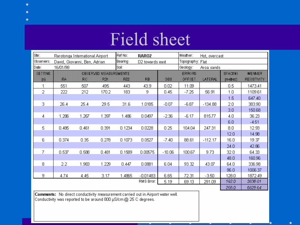
Field sheet
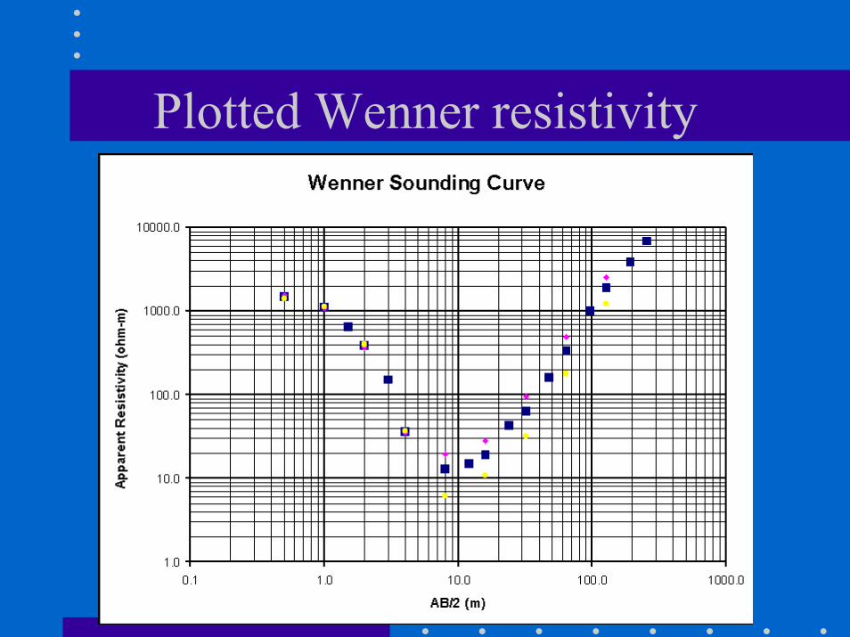
Plotted Wenner resistivity
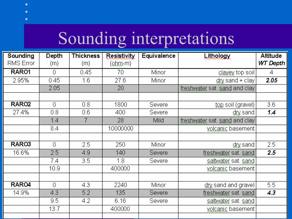
Sounding interpretations

Interpreted resistivity values

Sounding #2 - Airfield
Trouble shooting

Interpretation