using simulink in signal processing...
TRANSCRIPT
09/03/11 EC4440.MPF - Simulink Introduction 1
Using Simulink in Signal Processing Applications
09/03/11 EC4440.MPF - Simulink Introduction 2
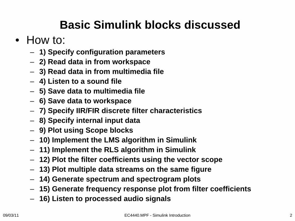
Basic Simulink blocks discussed• How to:
– 1) Specify configuration parameters– 2) Read data in from workspace– 3) Read data in from multimedia file– 4) Listen to a sound file– 5) Save data to multimedia file– 6) Save data to workspace– 7) Specify IIR/FIR discrete filter characteristics– 8) Specify internal input data– 9) Plot using Scope blocks– 10) Implement the LMS algorithm in Simulink– 11) Implement the RLS algorithm in Simulink– 12) Plot the filter coefficients using the vector scope– 13) Plot multiple data streams on the same figure– 14) Generate spectrum and spectrogram plots– 15) Generate frequency response plot from filter coefficients– 16) Listen to processed audio signals
09/03/11 EC4440.MPF - Simulink Introduction 3
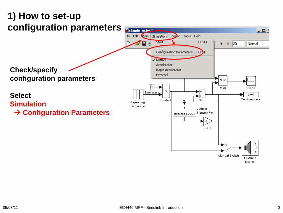
Check/specify configuration parameters
SelectSimulation
Configuration Parameters
1) How to set-up configuration parameters
09/03/11 EC4440.MPF - Simulink Introduction 4
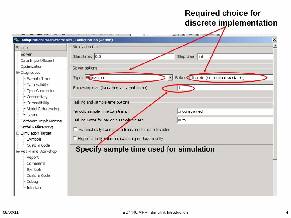
Specify sample time used for simulation
Required choice for discrete implementation

09/03/11 EC4440.MPF - Simulink Introduction 5
2) How to read data from the workspaceSelectSimulink
SourcesFrom Workspace

09/03/11 EC4440.MPF - Simulink Introduction 6
1) Data must be formatted as ynn2=[timesample,datasample], format: N 2
2) Need to define –timesample- with the correct sampling frequency
INPUT DATA FORMAT
09/03/11 EC4440.MPF - Simulink Introduction 7
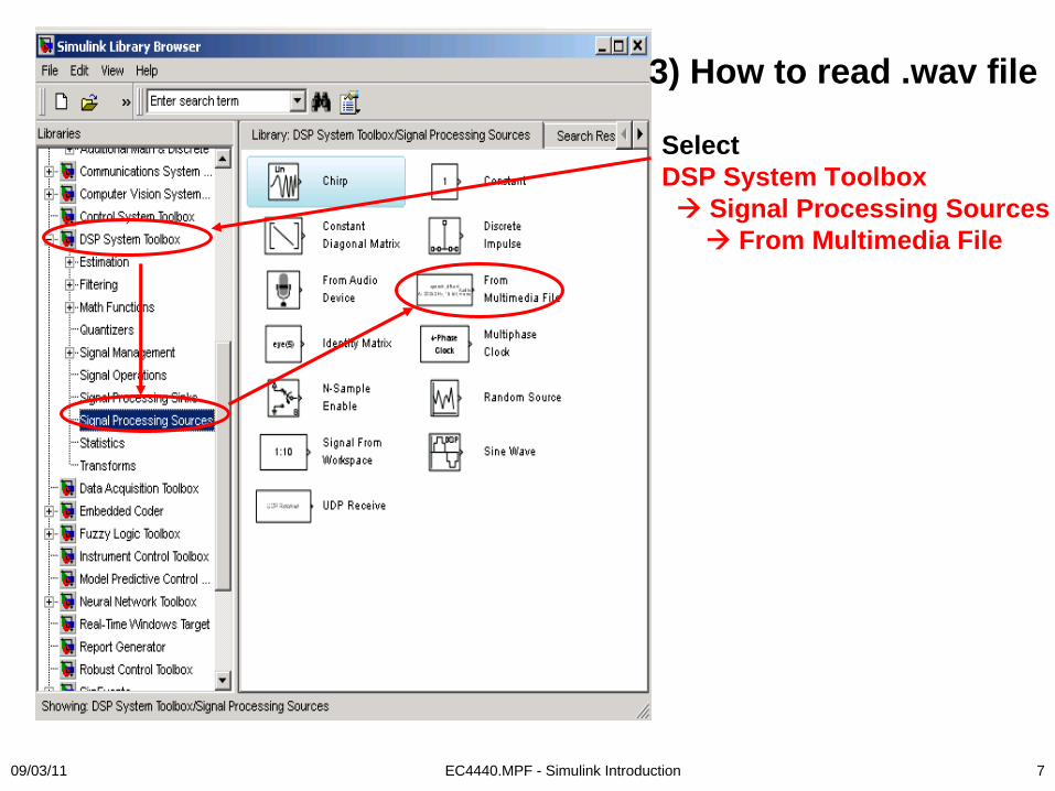
3) How to read .wav file
Select DSP System Toolbox
Signal Processing SourcesFrom Multimedia File

09/03/11 EC4440.MPF - Simulink Introduction 8
09/03/11 EC4440.MPF - Simulink Introduction 9
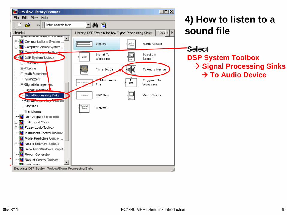
4) How to listen to a sound file
Select DSP System Toolbox
Signal Processing SinksTo Audio Device

09/03/11 EC4440.MPF - Simulink Introduction 10
5) Save data to a multimedia file
Select DSP System Toolbox
Signal Processing SinksTo Multimedia File
09/03/11 EC4440.MPF - Simulink Introduction 11
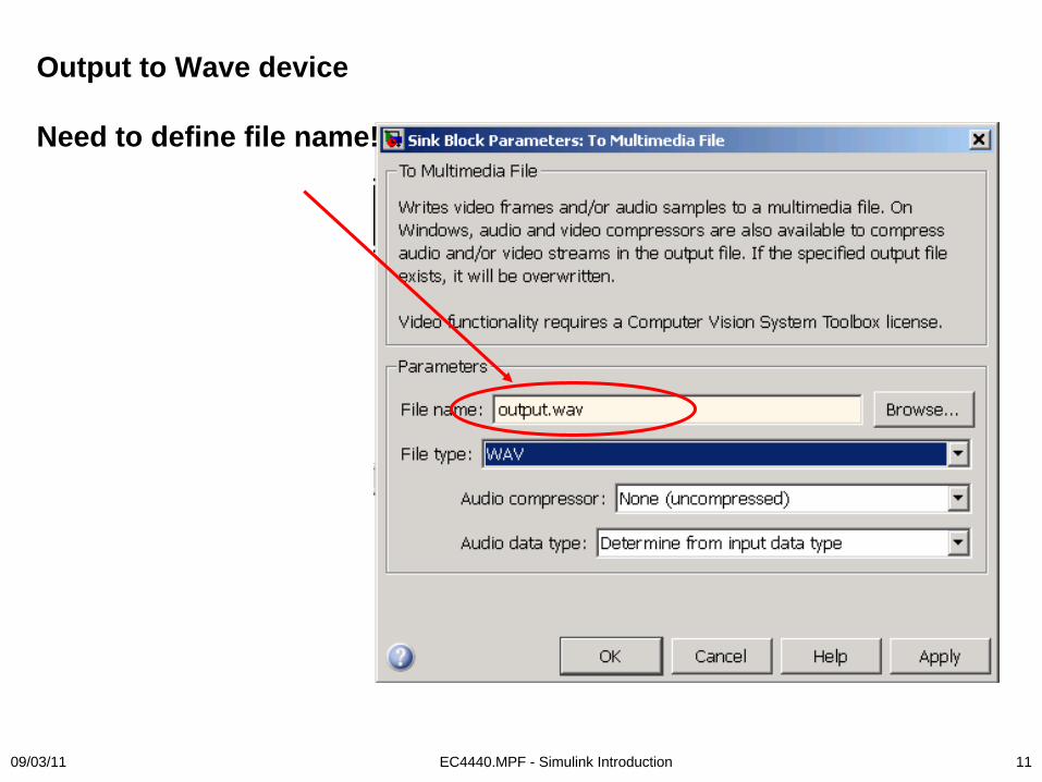
Output to Wave device
Need to define file name!
09/03/11 EC4440.MPF - Simulink Introduction 12
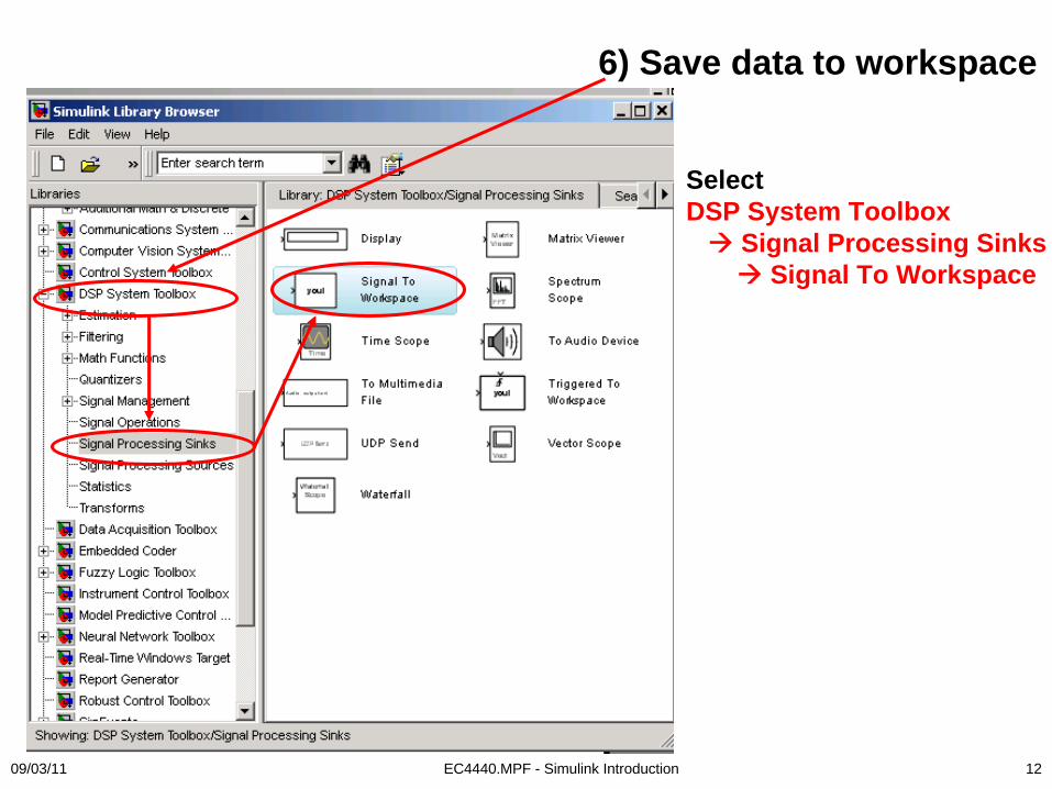
6) Save data to workspace
Select DSP System Toolbox
Signal Processing SinksSignal To Workspace

09/03/11 EC4440.MPF - Simulink Introduction 13
7) Specify IIR/FIR Filter characteristics
SelectSimulink
DiscreteDiscrete Filter

09/03/11 EC4440.MPF - Simulink Introduction 14
8) Specify internal input data
SelectSimulink
Sources
White Gaussian Noise
Sinewave
Uniform Random Noise
Specific parameters specified within each block

09/03/11 EC4440.MPF - Simulink Introduction 15
9) Plot data using Scope blocks
SelectSimulink
Sinks
2 options:
a) Floating Scope(need to specify inputs)
b) Scope(need to connect inputs)
09/03/11 EC4440.MPF - Simulink Introduction 16
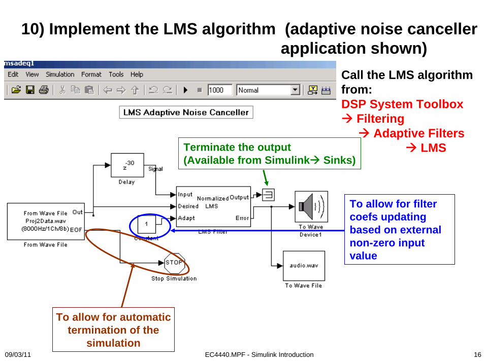
Call the LMS algorithm from:DSP System Toolbox
FilteringAdaptive Filters
LMS
To allow for automatic termination of the
simulation
Terminate the output (Available from Simulink Sinks)
To allow for filter coefs updating based on external non-zero input value
10) Implement the LMS algorithm (adaptive noise canceller application shown)
09/03/11 EC4440.MPF - Simulink Introduction 17
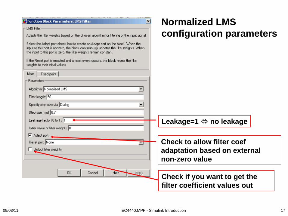
Leakage=1 no leakage
Check to allow filter coef adaptation based on external non-zero value
Check if you want to get the filter coefficient values out
Normalized LMS configuration parameters

09/03/11 EC4440.MPF - Simulink Introduction 18
LMS step size can be varied using the “slider gain”
SimulinkMath Operations
09/03/11 EC4440.MPF - Simulink Introduction 19
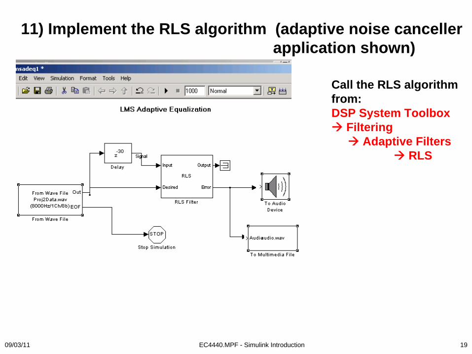
11) Implement the RLS algorithm (adaptive noise canceller application shown)
Call the RLS algorithm from:DSP System Toolbox
FilteringAdaptive Filters
RLS
09/03/11 EC4440.MPF - Simulink Introduction 20
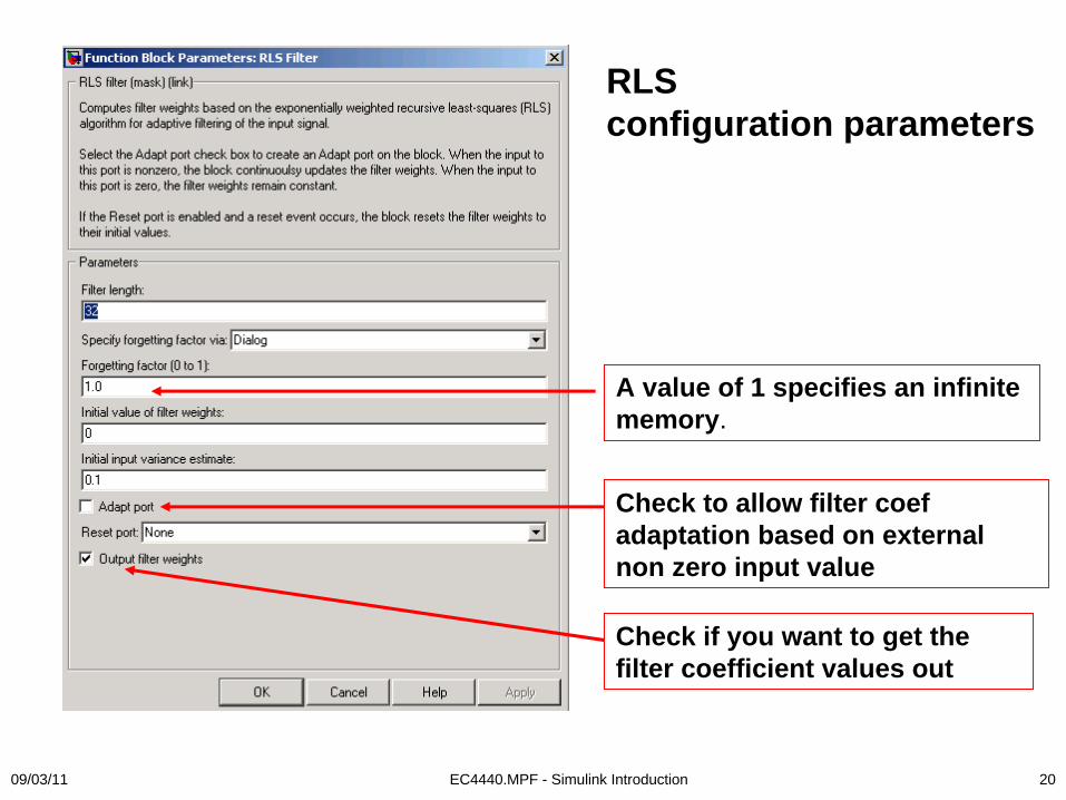
RLS configuration parameters
Check to allow filter coef adaptation based on external non zero input value
Check if you want to get the filter coefficient values out
A value of 1 specifies an infinite memory.
09/03/11 EC4440.MPF - Simulink Introduction 21
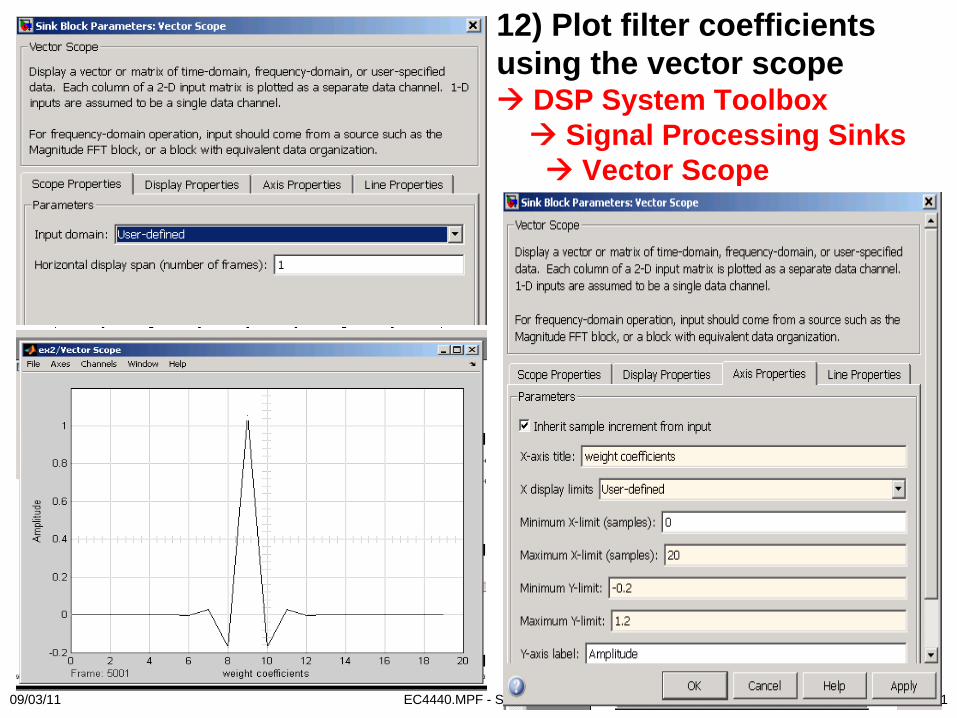
12) Plot filter coefficients using the vector scope
DSP System Toolbox Signal Processing Sinks
Vector Scope
09/03/11 EC4440.MPF - Simulink Introduction 22
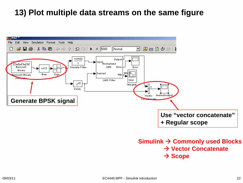
13) Plot multiple data streams on the same figure
Use “vector concatenate”+ Regular scope
Simulink Commonly used BlocksVector ConcatenateScope
Generate BPSK signal

09/03/11 EC4440.MPF - Simulink Introduction 23
14) Generate spectrum and spectrogram plotsSpecta.mdl (provided in course material)
09/03/11 EC4440.MPF - Simulink Introduction 24
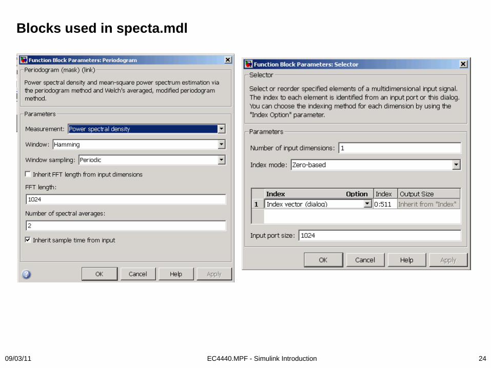
Blocks used in specta.mdl
09/03/11 EC4440.MPF - Simulink Introduction 25
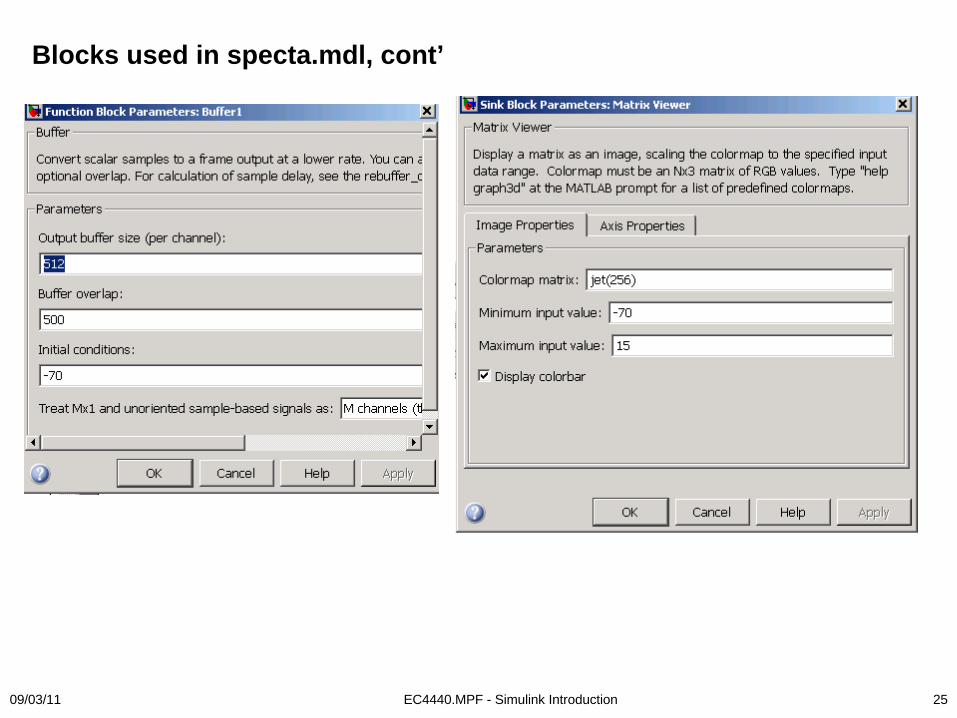
Blocks used in specta.mdl, cont’
09/03/11 EC4440.MPF - Simulink Introduction 26
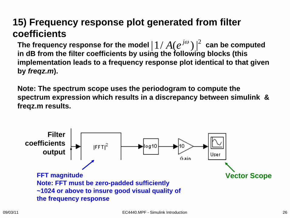
The frequency response for the model can be computed in dB from the filter coefficients by using the following blocks (this implementation leads to a frequency response plot identical to that given by freqz.m).
Note: The spectrum scope uses the periodogram to compute the spectrum expression which results in a discrepancy between simulink & freqz.m results.
2|1/ ( ) |jA e ω
15) Frequency response plot generated from filter coefficients
FFT magnitudeNote: FFT must be zero-padded sufficiently ~1024 or above to insure good visual quality of the frequency response
Filter coefficients
output
Vector Scope
09/03/11 EC4440.MPF - Simulink Introduction 27
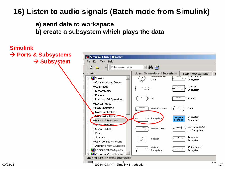
16) Listen to audio signals (Batch mode from Simulink)a) send data to workspaceb) create a subsystem which plays the data
Simulink Ports & Subsystems
Subsystem

09/03/11 EC4440.MPF - Simulink Introduction 28
c) Remove subsystem input/output ports
09/03/11 EC4440.MPF - Simulink Introduction 29
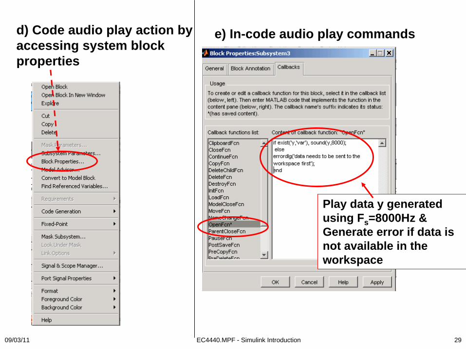
d) Code audio play action by accessing system block properties
e) In-code audio play commands
Play data y generated using Fs =8000Hz &Generate error if data is not available in the workspace

09/03/11 EC4440.MPF - Simulink Introduction 30