using the festo iot gateway in enterprise networks · the solution is deployed using a standard...
TRANSCRIPT

USING THE FESTOIoT GATEWAY INENTERPRISE NETWORKS

Abstract - The purpose of the Festo IoT Gateway device is toallow for a communication between the factory floor and thecloud. Traditionally production networks are completelyseparated from the Internet. This application note describes asolution using Debian GNU/Linux in a virtual machine toconnect the IoT Gateway to the Festo Cloud while complyingwith state of the art security recommendations. We proposemicro-segmentation using tagged VLAN to separate the IoTGateway ’Cloud’ port from the enterprise network. In thisdocument we show how to set up a separate network withfirewall rules to control all communication to and from the IoTGateway. This application note is intended to provide a low costapproach for small companies but the concepts also apply tomore complex enterprise networks with hardware firewalls.
I. INTRODUCTION Network security is a vitalpart of protecting theconfidentiality, availabilityand integrity of companiesassets. Informationtechnology (IT) security haslong been a concern for ITsystems in the office.Firewalls separatingnetworks from each otherare common place. Userand host authenticationwith elaborate authorizationmechanisms arewidespread and providesafeguards againstadversaries.2
Fig. 1. Bottom part of the process control/automation pyramid
Author:Thomas Ruschival
commands response
Level 2:DCS/SCADA
Level 1:Control/PLC
Level 0: Field

Traditionally, Industrial ControlSystems were isolated systemswith proprietary software andcommunication protocols. Thecommunication architecture ofthe process control zone wasstrictly hierarchical in the sensethat communication is alwaysinitiated from top to bottom andonly occurs between adjacentlayers. In this architecture lowerlayers respond to requests orcommands from the next higherlayer. Figure 1 shows theclassical process pyramidarchitecture.
Figure 2 formalizes this common approach and give security recommendationspublished in ISA99 ”Industrial Automation and Control Systems Security” by theInternational Society of Automation (ISA) and later harmonized as internationalstandard IEC62443 1. The architecture is conceptually separated into levels andzones. This is a theoretical approach, in concrete setups the layers may blur.Firewalls between the zones provide fine granular control over which hosts areallowed to communicate over which protocol with hosts in another network.
The enterprise zone comprises global enterprise resource planning (ERP) on level 5and site local office networks on level 4. The office network includes file servers andoffice workstations and wireless devices. The hosts in the office network usuallyhave outbound Internet access using common protocols like HTTP, HTTPS or others.The traffic is routed through The Internet Connection Sharing (ICS) firewall and theperimeter firewall. Proxy servers or stateful packet inspection can be used in the ICSfirewall to monitor communication content or encapsulated protocols.
The companies network is separated from the internet by the ’perimeter firewall’.Only a well-known set of protocols is allowed to connect from the hosts enterprisenetwork to the Internet. Request from the Internet on specific ports are forwarded tohosts located in the demilitarized zone (DMZ). A typical example of a host in theDMZ is the company web server that responds to HTTP(S) requests from theInternet. Additionally intrusion protection systems (IPS) can be deployed on theperimeter firewall to detect abnormal communication patterns. The manufacturingzone comprises all IT systems for plant operations on the site. A manufacturing zonefirewall (MZ) may be deployed to separate access to and from the demilitarized zone.
The Manufacturing zone often maintains a separate network infrastructure withdedicated DHCP, DNS and file servers. Typical level 3 systems are manufacturingexecution systems, plant historian servers, and engineering systems 2.
The systems in the process control zone control one specific manufacturing processor cell. SCADA or DCS systems are found in level 2. Level 1 contains programmablelogic controllers (PLC) or application specific controllers. Level 0 comprises sensorsand actuators connected to the PLCs via field buses, industrial Ethernet or directly wired.3
Level 1: Control network, PLC
Level 5: Enterprise network, ERP
Level 4: Site office network
Demilitarized Zone
Level 2: Area/Plant SCADA or DCS
Level 3: Site MES system
Level 0: Industrial fieldbusProc
ess
cont
rol z
one
Man
ufac
turing
zon
eAut
omat
ion
netw
ork
Ente
r-pr
ise
zone
ICS Firewall
MZ Firewall
Firewall/Network segregation
Perim
eter
Fire
wal
l
Fig. 2. Control hierarchy zones adapted from ISA99

The hosts on the manufacturing zone are critical assets for the company.Compromised participants may affect production, product quality and company tradesecrets. As additional challenge the hosts in the manufacturing zone run out datedversions of operating systems and cannot be easily upgraded due to functionalrestrictions.
According to the strictly hierarchical approach host on the automation networkusually have no Internet connection. It is not advised to grant direct access from theInternet or the enterprise zone to the manufacturing zone.
A. New challenges and architectural changesMany existing communication architectures where planned according to Figure 2.However, following this architecture some use-cases are difficult to implement. Forinstance synchronization of the MES system with ERP systems require access fromthe enterprise network. Remote monitoring for service companies or manufacturersto devices introduce direct channels from field devices to Internet sites. For instanceremote monitoring services of assets using GSM communication. Other companiesoffer remote service for equipment and systems 3. However these accesses areconducted through a specifically designed manner. Any of these scenarios mustguarantee the strict separation of production control and secondary functions likepredictive maintenance. This holds in particular for safety related systems.
NAMUR, the association of process automation operators has launched the project“NAMUR Open Architecture (NOA)” 4. The goal of the project is to developarchitectures that allow a second communication channel for read-only access toinformation in field devices while leaving the hierarchy for control intact.
The Festo IoT Gateway is designed to accommodate these bypass channels foraccessing data generated in the field.
B. The Festo IoT GatewayThe Festo IoT Gateway allows to connect to the Festo Cloud running on MicrosoftAzure infrastructure. TCP ports for cloud applications cannot be easily changed sincethe same software is shared by all customers.
To keep the IoT gateway deployment and configuration as simple as possible thedevice relies on a DHCP server for network configuration. Only in rare cases manualconfiguration using the Festo Automation Suite is required.
As basic device security design consideration all communication is established fromthe IoT Gateway. The device does not respond to any incoming packets on the’Cloud’ Port, including ICMP packets such as ping.
For confidentiality and authentication device and cloud communicate over TLS 1.2channels. During production the IoT gateway generates a unique public key certificate.The public key is distributed and the private key securely stored in the device. All IoTgateways also have public keys of the Festo Cloud application. Together thesecertificates grant secure authentication of both communication partners.
4
II. CHALLENGESLarge scale remote access facilities do not attend the requirements of small machineoperators or equipment manufacturers selling applications to a large variety ofcustomers. For one these systems require trained personnel for installation andoperation and are often considered too expensive to deploy ’just’ for predictivemaintenance. Enterprise IT has to guarantee network security and availability. Strictand sometimes complex policies regulate installation and network access of devices.These policies do not yet cover use-cases of new device like the Festo IoT Gateway.In this application note we suggest at cost efficient solution to provide field levelinformation in the cloud without circumvention of established security designprinciples in the network.
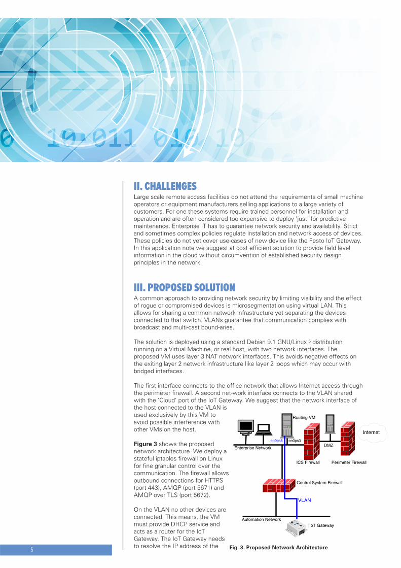
III. PROPOSED SOLUTIONA common approach to providing network security by limiting visibility and the effectof rogue or compromised devices is microsegmentation using virtual LAN. Thisallows for sharing a common network infrastructure yet separating the devicesconnected to that switch. VLANs guarantee that communication complies withbroadcast and multi-cast bound-aries.
The solution is deployed using a standard Debian 9.1 GNU/Linux 5 distributionrunning on a Virtual Machine, or real host, with two network interfaces. Theproposed VM uses layer 3 NAT network interfaces. This avoids negative effects onthe exiting layer 2 network infrastructure like layer 2 loops which may occur withbridged interfaces.
The first interface connects to the office network that allows Internet access throughthe perimeter firewall. A second net-work interface connects to the VLAN sharedwith the ’Cloud’ port of the IoT Gateway. We suggest that the network interface ofthe host connected to the VLAN isused exclusively by this VM toavoid possible interference withother VMs on the host.
Figure 3 shows the proposednetwork architecture. We deploy astateful iptables firewall on Linuxfor fine granular control over thecommunication. The firewall allowsoutbound connections for HTTPS(port 443), AMQP (port 5671) andAMQP over TLS (port 5672).
On the VLAN no other devices areconnected. This means, the VMmust provide DHCP service andacts as a router for the IoTGateway. The IoT Gateway needsto resolve the IP address of the5
DMZEnterprise Network
Automation Network
Perimeter FirewallICS Firewall
Control System Firewall
IoT Gateway
Routing VM
Internet
VLAN
en0ps8 en0ps3
Fig. 3. Proposed Network Architecture

Festo Cloud services. In the proposed solution the VM does not run a Domain NameSystem (DNS) server, hence we additionally allow DNS requests (port 53) to beforwarded to the enterprise or public DNS server.
For this solution to work the perimeter firewall must allow outbound HTTPS (port443) and AMQP over TLS connections on TCP port 5671 and 5672.
A. IP configurationWe use the Debian package net-tools to configure the network using listing 1 in/etc/network/interfaces. The interface enp0s3 is connected to the office network. Itexpects to receive IP configuration from the company DHCP server. The secondinterface enp0s8, connected to the VLAN is configured with a static IP address. Fordetails see 6.
1 #/etc/network/interfaces23 source /etc/network/interfaces.d/*45 # The loopback network interface6 auto lo7 iface lo inet loopback89 # The primary network interface10 allow-hotplug enp0s311 iface enp0s3 inet dhcp12 allow-hotplug enp0s813 iface enp0s8 inet static14 address 192.168.133.254/24
Listing 1. /etc/network/interfaces
B. DHCP configurationDHCP server is provided by the package isc-dhcp-server which uses theconfiguration listing 2 in /etc/default/isc-dhcp-server and listing 3 in/etc/dhcp/dhcpd.conf. To avoid interference with the company DHCP-server on theoffice-network we configure the server to only listen on en0ps8 i.e. the networkinterfaces connected to the IoT Gateway.
1 #/etc/default/isc-dhcp-server23 INTERFACESv4="enp0s8"4 INTERFACESv6=""
Listing 2. /etc/default/isc-dhcp-server
In the minimal setup in listing 3, we provide the IoT Gatway with a valid IP address,routing information and the company nameserver, here ns1.company.com. Fordetails see 7.
6

1 #/etc/dhcp/dhcpd.conf23 default-lease-time 600;4 max-lease-time 7200;5 ddns-update-style none;6 subnet 192.168.133.0 netmask 255.255.255.0 {7 range 192.168.133.1 192.168.133.2;8 option domain-name-servers ns1.company.com ;9 option domain-name "gateway.iot";10 option routers 192.168.133.254;11 option broadcast-address 192.168.133.255;12 default-lease-time 600;13 max-lease-time 7200;14 }
Listing 3. /etc/dhcp/dhcpd.conf
C. Iptables firewall configurationNetfilter iptables is the most common firewall tech-nology on linux and enabled inthe default Debian Linux kernel configuration. Listing 4 shows an executableshellscript to setup the firewall. The rules use a white-listing approach denying alltraffic that is not explicitly allowed. For details on the syntax see 8.
1 #!/bin/bash23 #nterface to Festo Device4 INIF="enp0s8"5 # Interface to Customer6 OUTIF="enp0s3"78 # set chain policy of each chain to ACCEPT9 iptables -P INPUT DROP10 iptables -P FORWARD ACCEPT11 iptables -P OUTPUT DROP1213 # flush all rules14 iptables -F15 iptables -F -t nat16 # delete user-defined chains17 iptables -X18 # set packet counter to zero19 iptables -Z2021 # accept established incoming connections22 iptables -A INPUT -i $INIF -m conntrack \23 --ctstate ESTABLISHED,RELATED -j ACCEPT24 # accept outgoing DNS-traffic25 iptables -A INPUT -i $INIF -p udp \26 --sport 53 -j ACCEPT27 # accept DHCP Requests28 iptables -A INPUT -i $INIF -p udp \29 --dport 67 -j ACCEPT30 #31 iptables -A OUTPUT -o $OUTIF -p udp \
7

32 --dport 53 -m conntrack \33 --ctstate NEW,ESTABLISHED,RELATED -j ACCEPT34 # accept outgoing HTTPS traffic35 iptables -A OUTPUT -o $OUTIF -p tcp \36 --dport 443 -m conntrack \37 --ctstate NEW,ESTABLISHED,RELATED -j ACCEPT38 # accept outgoing AMQP traffic39 iptables -A OUTPUT -o $OUTIF -p tcp \40 --sport 5671 -m conntrack \41 --ctstate NEW,ESTABLISHED,RELATED -j ACCEPT42 # accept outgoing AMQP traffic43 iptables -A OUTPUT -o $OUTIF -p tcp \44 --sport 5672 -m conntrack \45 --ctstate NEW,ESTABLISHED,RELATED -j ACCEPT4647 # NAT of connections48 iptables -t nat -I POSTROUTING \49 -o $OUTIF -j MASQUERADE5051 #enable IP-forwarding in the kernel52 echo "1" > /proc/sys/net/ipv4/ip_forward
Listing 4. /usr/sbin/firewall.sh
D. Port based authenticationAt the moment the IoT gateway does not support IEEE 802.1X port basedauthentication 9. MAC Address Bypass (MAB) can be implemented to use the FestoIoT Gateway in a IEEE 802.1X enabled network. This has been successfully tested inthe Festo IT.
IV. CONCLUSIONPublishing information from manufacturing devices to the Internet is a sensitiveundertaking and requires thorough planning. This application note shows how toconnect the Festo IoT Gateway to the Internet while maintaining the networkarchitecture for all other network hosts. The current proposed setup shows only oneeasy low cost implementation while maintaining a high standard for the security ofthe customer enterprise network. The IoT gateway will also work with otherenterprise grade firewall vendors like Cisco, Fortinet, or SonicWall. The IoT Gatewayhas been integrated and tested at Festo in a Cisco CPwE 10 certified network.
8
REFERENCES[1] IEC, “Industrial automation and control systems security,” International Electrotechnical Commission, Geneva, CH, Standard 62443-1, 2009.[2] “Secure architecture for industrial control systems,” SANS, 2015.[Online]. Available: https://www.sans.org/reading-room/whitepapers/ICS/secure-architecture-industrial-control-systems-36327[3] “Siemens - SIMATIC Remote Services,” https://support.industry. siemens.com/cs/sc/2281/simatic-remote-services, accessed: 2018-01-11.[4] C. K. und Thomas Tauchnitz und Ulrich Epple und Lars Nothdurft und Christian Diedrich und Tizian Schroder und Daniel Grossmann und Suprateek Banerjee und Michael Krau und Chris Iatrou und Leon Urbas, “Namur open architecture,” atp edition, vol. 59, no. 01-02, pp. 20–37, 2017. [Online]. Available: http://ojs.di-verlag.de/index.php/atp edition/article/view/620[5] “Osboxes - debian 9.1 virtual box images,” https://www.osboxes.org/debian/, accessed: 2018-01-22.[6] “Debian - /etc/network/interfaces, man (5) interfaces,” https://manpages.debian.org/jessie/ifupdown/interfaces.5.en.html, accessed: 2018-01-19.[7] “Isc - dhcp server configuration, man (5) dhcpd.conf,” https: //linux.die.net/man/5/dhcpd.conf.[8] “netfilter iptables /etc/network/interfaces, man (8) iptables,” https://linux.die.net/man/8/iptables, accessed: 2018-01-19.[9] “Ieee standard for local and metropolitan area networks–port-based network access control,” IEEE Std 802.1X-2010 (Revision of IEEE Std 802.1X-2004), pp. 1–205, Feb 2010.[10] “Cisco - cpwe converged plantwide ethernet (cpwe) design and implementation,” accessed: 2018-01-29. [Online]. Avail-able: https://www.cisco.com/c/en/us/td/docs/solutions/Verticals/CPwE/CPwE DIG/CPwE chapter1.html