using touch interface in harsh environments - nxp.com user control interface is another factor to...
TRANSCRIPT

Freescale Semiconductor, Inc.Application Note
© 2015 Freescale Semiconductor, Inc. All rights reserved.
1 IntroductionThe touch-sensing method is used to replace most of traditional tact switch inputs as a new type of human-machine interface used in home-appliance applications. However, using such kind of detection method in harsh environment is still a challenge for most of product designers. A good balance of fast response and no false trigger in key detection is always an essential factor for the user-interface design. The touch-sensing input (TSI) module in Freescale MCUs provides capacitive touch detection with high sensitivity and durability, which can help customers to adapt this kind of human touch-sensing technology quicker. This application note describes how to use the S08PT family MCU features in applications with emphasis on both touch-sensing interface and safety aspect. Different techniques in circuit design, intelligent software control and reliable mechanical structure are illustrated in this application note to show how to achieve a product design with protection features for handling faults and fast TSI response without any false trigger in extreme conditions. Most of the critical scenarios and unexpected use cases from the end-user point of view must be fully studied and well-covered in advance to prevent any serious flaw
Document Number: AN5060Rev. 0, 01/2015
Contents1. Introduction . . . . . . . . . . . . . . . . . . . . . . . . . . . . . . . . . 12. System overview . . . . . . . . . . . . . . . . . . . . . . . . . . . . . 23. Hardware design . . . . . . . . . . . . . . . . . . . . . . . . . . . . . 34. Firmware design . . . . . . . . . . . . . . . . . . . . . . . . . . . . . 45. Conclusion . . . . . . . . . . . . . . . . . . . . . . . . . . . . . . . . 116. References . . . . . . . . . . . . . . . . . . . . . . . . . . . . . . . . . 12
Using Touch Interface in Harsh Environmentsby: Dennis Lui and T.C. Lun

Using Touch Interface in Harsh Environment, Application Note, Rev. 0, 01/2015
2 Freescale Semiconductor, Inc.
System overview
persisting in the final design stage which causes significant delay in the whole project schedule.
2 System overviewA completed microwave oven design with touch interface using the MC9S08PT60 MCU (PT60) is developed as a quick-start solution for the customers working on similar product designs with safety requirements. The documents AN4476: System Design Guideline for 5V 8-bit families in Home Appliance Applications and AN4463: How to Develop a Robust Software in Noise Environment available on freescale.com provide a detailed description of EMC design considerations. This application note focuses only on hardware, firmware and mechanical design techniques for safety enhancement.
Figure 1. System block diagram
The microwave oven system block diagram is shown in Figure 1. The AC power line voltage is transformed down and regulated to 12 V and 5 V in the power supply module. All power relay switches are controlled by 12 V driving circuits, while the power stage high currents are drawn directly from the AC power line. The 5 V supply is the main supply for the whole system including the MCU, input / output, display, and temperature sensor circuit. However, the buzzer circuit is driven by 12 V.
The MC9S08PT60 MCU is used for all signal detections on the user interface, power stage controls with sequential order and system protection in fault conditions. During normal operation, an event triggered by the end-user through input touch keys is decoded in the MCU and the corresponding message or system status is shown on the LCD display as confirmation or indication. The control scheme for power stages must be able to turn the high-power devices on or off with limited voltage stress on the power line. The status of the oven door (open or closed) is monitored periodically as one of the error signals for system protection. The mechanical switch is used as a reliable method to cut off the ground connection for grill

Using Touch Interface in Harsh Environment, Application Note, Rev. 0, 01/2015
Freescale Semiconductor, Inc. 3
Hardware design
and microwave power stages when the oven door is open. Different sound patterns generated from the buzzer are used as alert signals when fault conditions are detected.
3 Hardware designA serial-bus-controlled LCD driver for the LCD panel used in this hardware design is a good choice to balance the effort spent on circuit design and the cost of using high pin count package. Other discrete LED indicators are controlled by six input / output pins using the scanning method. Dedicated input / output pins are reserved for critical power stage controls, touch key scanning and real-time monitoring of system status. The detailed descriptions for each circuit portion are shown in the following subsections. See Figure 8, and Figure 9 for all reference symbols.
3.1 LCD driving and scanning
A simple LCD panel with 13 segments and four backplanes is used as the display for basic text information and it is driven by a serial-bus-controlled LCD driver, which can help to simplify the hardware design and provide more flexibility on supporting different LCD panel modules. The backlight of the LCD display is controlled by a dedicated MCU input / output pin.
The discrete LED indicators are divided into three groups; only one of the groups can be active at a time. The status of each active group is set by the value applied at the segment pins (LED_COM0/1/2). Each group is selected alternately by using a scanning method and can be further extended to combine with an additional scanning task in different time slots if necessary.
3.2 TSI scanning
The usage of TSI provides a simple way to increase key detection sensitivity when compared to the traditional mechanical key input method. The TSI module in the PT60 supports up to 16 external electrodes; each active electrode must be enabled before scanning. Otherwise, the scan does not work or an invalid result will be asserted. However, the total noise getting into the TSI module could be much higher if all TSI electrode channels are set active, no matter if the channel is scanned or not. Each electrode channel setting in the active mode behaves as a floating pin in the non-scanning period. The floating pin structure is more sensitive to noise and it also provides an effective path for noise coupling from other circuits.
The TSI channels should be scanned sequentially with only one target channel being active at a time and other channels configured as output low. In case of a 16-channel scanning the floating time reduction is more than 90 %, which can help to eliminate external noises injected into the TSI pins in an idle state.
The side effect of high sensitivity is the issue with mistriggering when there is no user activity. The software design must be able to identify the touch event from other patterns triggered by noises.
3.3 Temperature detection
One of the ADC channels is used to measure the voltage generated by a sensor in different temperature conditions. The characteristic curve of the sensor output against the temperature or simply a pre-defined
Using Touch Interface in Harsh Environment, Application Note, Rev. 0, 01/2015
4 Freescale Semiconductor, Inc.
Firmware design
threshold level is stored in the flash memory for direct table look-up or over-threshold detection method, to identify whether the system is working properly or overheats in high temperature conditions.
3.4 Power stage control
All high-voltage driving circuits are isolated from the control board using a standard power relay as a control switch to protect the system in case of a fault. The control sequence in power stages is a critical design parameter to ensure that the system is able to operate in safe conditions. The mechanism of power stage controls is described as follows:
• Both the Grill and Microwave functions are prohibited if the Fan function is not yet enabled.
• The Grill and Microware functions are independent; either one or both can be selected.
• The Motor function is enabled automatically when the Fan function is active.
• Both the Grill and Microwave functions are forced to shutdown immediately in case the oven door is opened. The circuit ground point is disconnected by a mechanical switch.
The Fan function should be enabled before the operation of Grill and Microwave functions to make sure the cooling system is running properly and to avoid overheating.
3.5 AC power detection
The AC power line frequency detection is a simple method to indicate whether the input power is stable or not. An optical coupler is used to transform the signal format to match the MCU input requirements. The coupling circuit is used to:
• Provide isolation between the AC power line and the MCU input
• Decrease the voltage to 5 V level for MCU detection
• Convert the sinusoidal signal into the square wave signal for frequency measurement in the MCU
The zero-crossing point of the sinusoidal AC signal indicates the best timing to switch a power device on or off with a minimum loading effect and low transient noise on the power system. Therefore, all power stages are not changed immediately when a command is received; the action will be delayed until the zero-crossing point is reached.
3.6 Alert messages
The 7-segment LCD display is used as a visual medium for displaying the status information, action confirmation, and error messages. The buzzer component is added into the system as an alternative to generate sound messages, particularly useful for alert messages when error conditions are detected. For example, a periodic ‘beep’ sound is generated when serious fault conditions are detected. This kind of acoustic alert message can catch the end user’s attention for a longer time and eliminates the sign limitation of a visual display.
4 Firmware designA proper firmware design with safety considerations improves the overall system performance, safety protection and operating stability in harsh environment. Most of the safety-related issues can be avoided

Using Touch Interface in Harsh Environment, Application Note, Rev. 0, 01/2015
Freescale Semiconductor, Inc. 5
Firmware design
if the MCU is able to control all functions in pre-defined sequences with minimum stress placed on the hardware modules. The user control interface is another factor to address the safety requirements.
The interface must be designed with helpful information on how to use the product quickly and the ability to keep the end users out of selecting a feature which is not allowed at the moment. It is not appropriate to accept all input triggers from the end users without any filtering; the firmware must understand the current situation and make right decisions on corresponding actions.
4.1 Firmware structure
The firmware includes all the necessary tasks for user input detection, display driving, power stage control, and safety protection which allow the product to work properly. The firmware structure consists of two parts:
• Main routine: Handles all tasks on a periodic basis.
• Interrupt routines: Handle specific tasks on an event-driven basis.
Figure 2 shows the main program flow and the timer interrupt routine.
Figure 2. Main program flow
The main program continually executes a series of subroutines after the system initialization in order to control the system according to user’s inputs and keep track of all conditions for safe operation. One of the Timer / Pulse-Width Modulation (TPM) modules is configured in the output compare mode to generate a periodic timing which is used as the core time base component for various software timers. An individual counter variable is assigned for each software timer. It counts up in the Timer interrupt routine and resets to zero when it reaches a pre-defined threshold. The final period for each software timer is equal to the

Using Touch Interface in Harsh Environment, Application Note, Rev. 0, 01/2015
6 Freescale Semiconductor, Inc.
Firmware design
core time base multiplied by the corresponding counter threshold. Software timers with different periods are assigned specific tasks with the timing concern in the main loop.
Figure 3 shows the flow of other interrupt routines, specifically the timer input capture interrupt for handling input events triggered by a square wave or pulse signals at rising or falling edges, the TSI interrupt for performing sequential channel scanning and the ADC interrupt to indicate the end of sampling for temperature detection.
• Zero-crossing interrupt – captures the AC power line frequency, updates the clock and detects the zero-crossing point for power stage output toggling
• TSI interrupt – selects the next TSI channel until all channels are scanned
• ADC interrupt – completes the ADC sampling and triggers the calculation of temperature
Figure 3. Interrupt routines

Using Touch Interface in Harsh Environment, Application Note, Rev. 0, 01/2015
Freescale Semiconductor, Inc. 7
Firmware design
4.2 Front panel description
The front panel is shown in Figure 4. End users can control the system using the front panel which consists of sixteen TSI functional keys for command input, a four-digit seven-segment display for system status or error message indication. The following subsections briefly discuss each of these.
Figure 4. Front panel
4.2.1 The seven-segment display
The 7-segment display provides a simple way to indicate the system status, error messages or acknowledgement for user input. The display information is limited to a set of characters which can be mapped using a seven-segment format in terms of shape. For example, the character ‘T’ is represented by symbol ‘’, but there are no capital letters for ‘B’ or ‘R’ because the shape of ‘B’ is the same as the number ‘8’ in seven-segment format and the shape of ‘R’ closely resembles the letter ‘A’. The details of messages using this design are shown in Table 1.

Using Touch Interface in Harsh Environment, Application Note, Rev. 0, 01/2015
8 Freescale Semiconductor, Inc.
Firmware design
4.2.2 Function keys
There are five function keys for user input:
• MODE – selects one of the operating modes:
— Mode 1 – enables the Fan function only; this mode is used for testing purposes
— Mode 2 – enables the Fan and Grill functions
— Mode 3 – enables the Fan and Microwave functions
— Mode 4 – enables the Fan, Grill and Microwave functions
• START – starts or confirms the process
• STOP – stops or cancels the process
• TSI_0 – 7 – reserved for further development
• TSI_11 – 15 – reserved for further development
• N/A – no touch functions
4.2.3 Mechanical switch
A mechanical switch is used to lock or release the front door. The open door condition is always detected and shown on the display as an alert message for the user.
• In Stop condition – the message ‘Open’ is displayed when the door is open
• In Start condition – the message ‘Error’ is displayed when the door is open
4.3 Random delay function
The use of multiple reads on change of state is a common practice to eliminate any fault alarm triggered by random noises. However, this method is not effective for a noise with periodic pattern that matches the
Table 1. Seven-segment display symbols
Seven-segment display symbols
Equivalent characters Description
norl Normal In normal condition
0 to 9 0 to 9 Numeric character from 0 to 9
OPT1/2/3/4 Operating Mode 1 / 2 / 3 / 4 Select the operating mode
STAr Start Start or confirm a process
STOP Stop Stop or cancel a process
noTA Not Allowed The action is not allowed
eror Error Indicates an error
ACer AC Error Error due to AC power
Ader ADC Error Error due to the ADC
OPEn Open The front door is open

Using Touch Interface in Harsh Environment, Application Note, Rev. 0, 01/2015
Freescale Semiconductor, Inc. 9
Firmware design
sampling frequency. A random delay time function must be added in each sampling time to make sure that there is no correlation to the periodic noise. The timing diagrams are shown in Figure 5.
Figure 5. Random delay timing
This type of random delay function can be achieved by reading the internal free-running TPM counter value. The two least significant bits of the counter value are rolling very fast and almost randomly, with respect to each time event for sampling. The actual delay is equal to the random 2-bit data multiplied by a fixed time interval.
4.4 TSI decoding
A touch event will increase the touch pad equivalent capacitance in a way that the corresponding counter value in the TSI module will be higher when compared to the baseline (no touch), so it is possible to detect a touch event if the counter reading is higher than a pre-defined threshold. However, the delta of the counter value for a touch is only 3% to 5% subject to the touch area, so this kind of simple threshold detection is not effective and mistriggerring by noises is possible even with multiple reads or averaging on the counter value.
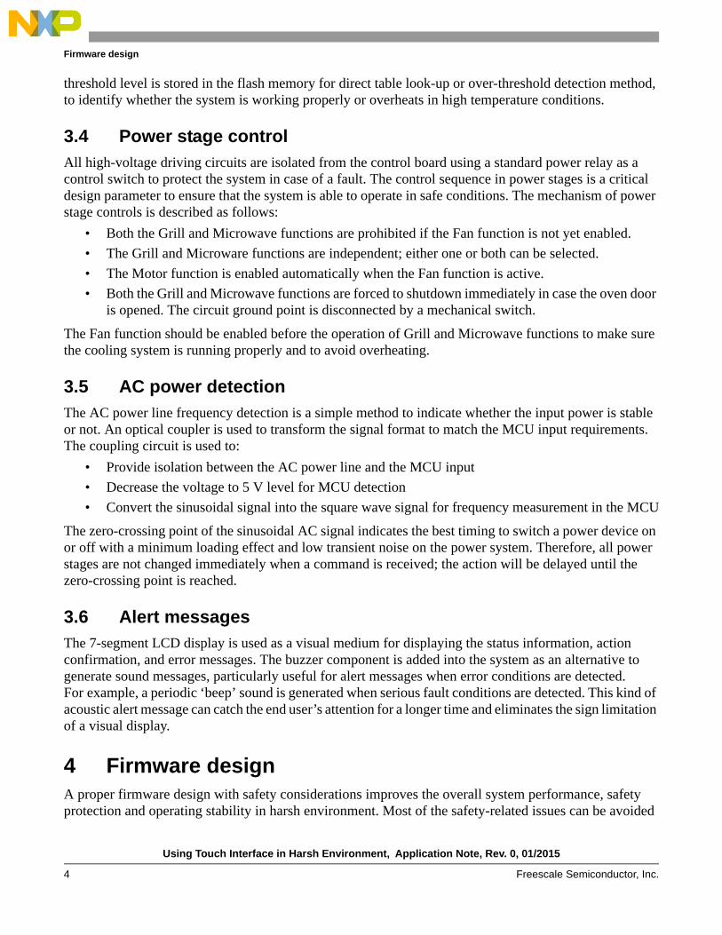
Figure 6 shows a touch detection method with more flexibility on timing selection to match the requirements for different applications. The balance of fast response and high noise immunity level can be adjusted according to the user’s feeling or the product specifications. Three timing parameters are used to define the rules for touch pattern recognition:
• T1 – defines the period from idle state to press state, the press state should be maintained for a couple of counter readings
• T2 – defines the period of the hold state after the press condition, holding too long is treated as a hold-up condition
• T3 – defines the idle time before the next detection; pressing multiple times very quickly is prohibited
Using Touch Interface in Harsh Environment, Application Note, Rev. 0, 01/2015
10 Freescale Semiconductor, Inc.
Firmware design
Figure 6. TSI decoding pattern
Examples of touch patterns are shown in Figure 6; only the B and E patterns are recognized as valid touch events and properly released for next detection. The touch action of pattern A is too fast and it would be considered as a glitch pattern generated by noises. The holding time of pattern C is too long and the system is affected by a continuous background noises. The idle time of pattern D is too short and it is not sufficient for a release condition.
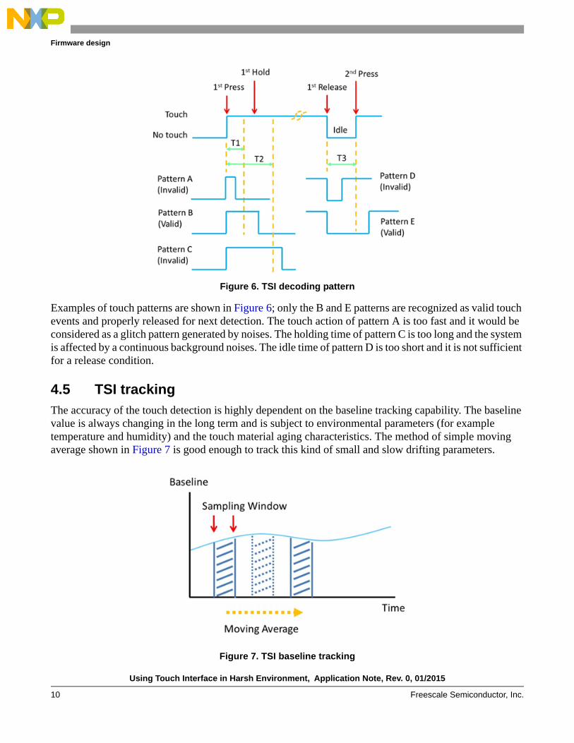
4.5 TSI tracking
The accuracy of the touch detection is highly dependent on the baseline tracking capability. The baseline value is always changing in the long term and is subject to environmental parameters (for example temperature and humidity) and the touch material aging characteristics. The method of simple moving average shown in Figure 7 is good enough to track this kind of small and slow drifting parameters.
Figure 7. TSI baseline tracking

Using Touch Interface in Harsh Environment, Application Note, Rev. 0, 01/2015
Freescale Semiconductor, Inc. 11
Conclusion
Normally, the system will go through a similar process with faster sampling loop in the power-up state to calibrate all baseline values to speed up the initialization process for the TSI feature, and then performing the tracking process slowly in the background.
4.6 Protection features
Smart control of the operating flow is very important from the system protection point of view. The firmware must be able to identify the current status or conditions before processing any input requests. For example, the firmware must not turn on a power control stage if one or more pre-defined conditions are not fulfilled. The following protection rules are implemented in the system:
• The default operating mode is Mode 1 (See Section 4.2.2, “Function keys”) which means that the power control stages for the Grill and Microwave functions are kept in an inactive state until the user changes the state of the functions intentionally.
• Only the STOP key input is still being scanned when the START key input is detected. For example, the user cannot change the operating mode when the power stages are running. It must be stopped before changing the mode setting.
• In normal conditions, all active power control stages would be shut down immediately if the open door error is triggered. The shutdown process will be executed straight away irrespective of whether the zero-crossing point is reached or not and the ‘Error’ message is shown in the seven-segment display as an alert message. The periodic ‘beep’ sound is also generated continuously by the buzzer circuit until the front door is closed again.
• The alert message caused by the door being opened will be changed from ‘Error’ to ‘Stop’ when the front door is closed and the user must press the STOP key once to clear the error state. This is a friendly reminder to ensure that the user is aware of the fault condition and is ready to release the lock state for further operation.
• Measuring only the AC power line frequency for error checking is not safe enough. The measurement process will be suspended if the corresponding interrupt routine is not triggered periodically. The measurement routing is waiting for new data to calculate. It is necessary to have a dedicated timeout function for the AC power detection to make sure that an error signal is asserted when the signal was not toggled for a long time.
5 ConclusionA complete reference design with the TSI feature is illustrated as an example; it covers the safety considerations on the product design level and couples with hardware and software techniques for product enhancement from the safety point of view. The TSI pattern decoding with high noise immunity is used to avoid issues with mistriggering in touch-sensing applications. It can help customers to adapt the Freescale solutions in their products easier and faster.

Using Touch Interface in Harsh Environment, Application Note, Rev. 0, 01/2015
12 Freescale Semiconductor, Inc.
References
6 ReferencesThe following reference documents are available on freescale.com:
• AN4438 – EMC Design Considerations for MC9S08PT60
• AN4476 – System Design Guideline for 5V 8-bit families in Home Appliance Applications
• AN4463 – How To Develop a Robust Software in Noise Environment
• AN2321 – Designing for Board Level Electromagnetic Compatibility
• AN2764 – Improving the Transient Immunity Performance of Microcontroller-Based Applications
Using Touch Interface in Harsh Environment, Application Note, Rev. 0, 01/2015
Freescale Semiconductor, Inc. 13
Schematic 1
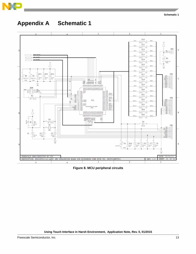
Appendix A Schematic 1
Figure 8. MCU peripheral circuits

Using Touch Interface in Harsh Environment, Application Note, Rev. 0, 01/2015
14 Freescale Semiconductor, Inc.
Schematic 2
Appendix B Schematic 2
Figure 9. LCD and LED driving circuits

Document Number: AN5060Rev. 001/2015
Information in this document is provided solely to enable system and software
implementers to use Freescale products. There are no express or implied copyright
licenses granted hereunder to design or fabricate any integrated circuits based on the
information in this document.
Freescale reserves the right to make changes without further notice to any products
herein. Freescale makes no warranty, representation, or guarantee regarding the
suitability of its products for any particular purpose, nor does Freescale assume any
liability arising out of the application or use of any product or circuit, and specifically
disclaims any and all liability, including without limitation consequential or incidental
damages. “Typical” parameters that may be provided in Freescale data sheets and/or
specifications can and do vary in different applications, and actual performance may
vary over time. All operating parameters, including “typicals,” must be validated for
each customer application by customer’s technical experts. Freescale does not convey
any license under its patent rights nor the rights of others. Freescale sells products
pursuant to standard terms and conditions of sale, which can be found at the following
address: freescale.com/SalesTermsandConditions.
How to Reach Us:
Home Page: freescale.com
Web Support: freescale.com/support
Freescale and the Freescale logo are trademarks of Freescale Semiconductor, Inc.,
Reg. U.S. Pat. & Tm. Off. All other product or service names are the property of their
respective owners.
© 2015 Freescale Semiconductor, Inc.