ut inspection of welding joins: issues and contribution of ... · pdf filecontext: weld...
TRANSCRIPT

UT inspection of welding joins: issues and contribution
of CIVA simulation tools

GENERAL CONTEXT: ISSUES AND PROBLEMS OF WELD INSPECTION BY ULTRASONIC METHODS
67th IIW Annual Assembly and International Conference | Pierre CALMON | 2
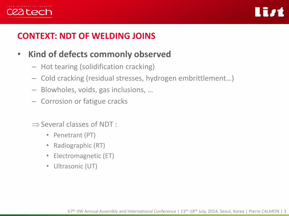
CONTEXT: NDT OF WELDING JOINS
• Kind of defects commonly observed – Hot tearing (solidification cracking)
– Cold cracking (residual stresses, hydrogen embrittlement…)
– Blowholes, voids, gas inclusions, …
– Corrosion or fatigue cracks
Several classes of NDT :
• Penetrant (PT)
• Radiographic (RT)
• Electromagnetic (ET)
• Ultrasonic (UT)
67th IIW Annual Assembly and International Conference | 13th-18th July, 2014, Seoul, Korea | Pierre CALMON | 3
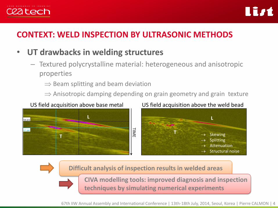
CONTEXT: WELD INSPECTION BY ULTRASONIC METHODS
• UT drawbacks in welding structures – Textured polycrystalline material: heterogeneous and anisotropic
properties
Beam splitting and beam deviation
Anisotropic damping depending on grain geometry and grain texture
67th IIW Annual Assembly and International Conference | 13th-18th July, 2014, Seoul, Korea | Pierre CALMON | 4
Difficult analysis of inspection results in welded areas
L
T
TIME
US field acquisition above base metal
L
T Skewing Splitting Attenuation Structural noise
US field acquisition above the weld bead
CIVA modelling tools: improved diagnosis and inspection techniques by simulating numerical experiments
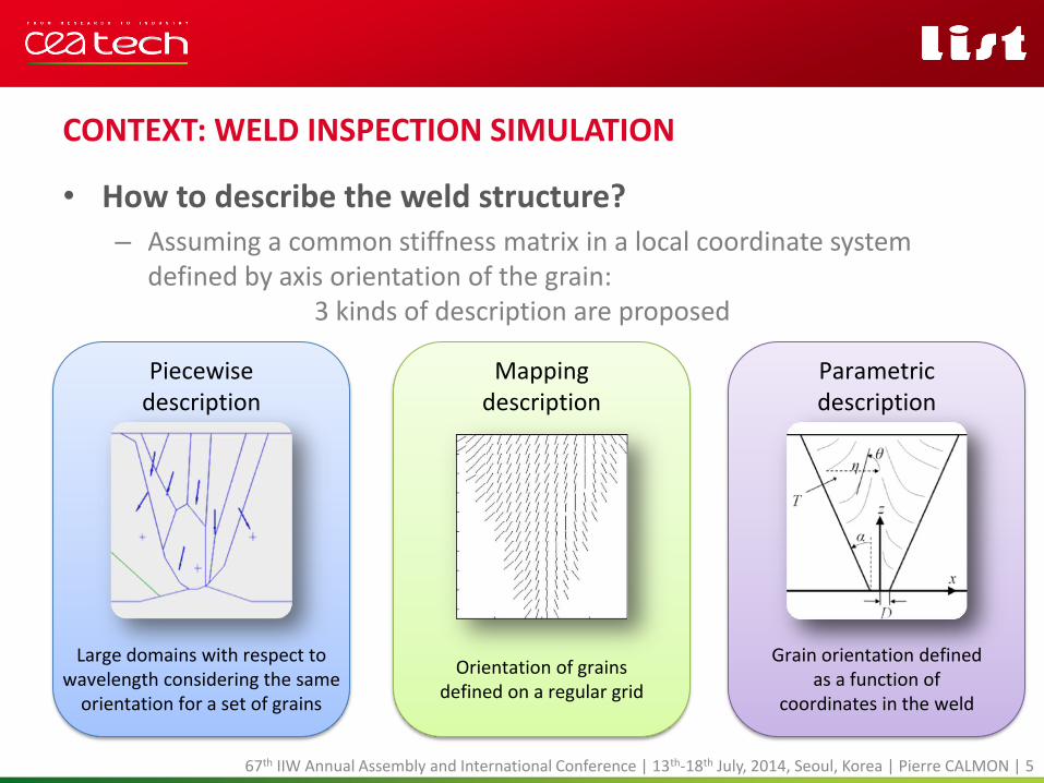
CONTEXT: WELD INSPECTION SIMULATION
• How to describe the weld structure? – Assuming a common stiffness matrix in a local coordinate system
defined by axis orientation of the grain: 3 kinds of description are proposed
67th IIW Annual Assembly and International Conference | 13th-18th July, 2014, Seoul, Korea | Pierre CALMON | 5
Piecewise description
Mapping description
Parametric description
Orientation of grains defined on a regular grid
Large domains with respect to wavelength considering the same
orientation for a set of grains
Grain orientation defined as a function of
coordinates in the weld

CONTEXT: WELD INSPECTION SIMULATION
• Piecewise description of grain orientation – Definition of large homogeneous domain with a unique
crystallographic orientation
• Derived from
– post-processing of macrographic images gathering, with a tolerance threshold, the grains according to their orientation around a common average axis
• Advantages and drawbacks
– easy to implement description
– unrealistic artefacts and wave mode conversions due to fictive interfaces
– excessive approximation or difficulties to divide any welds in domains with similar orientation
67th IIW Annual Assembly and International Conference | 13th-18th July, 2014, Seoul, Korea | Pierre CALMON | 6
Piecewise description

CONTEXT: WELD INSPECTION SIMULATION
• Mapping description of grain orientation – The grain orientation is given on a regular grid with a spatial sampling
depending on the process to define these orientations
• Derived from
– post-processing of macrographic images extracting orientation from gradient-based operators (OrientationJ, ImageJ's plugin for directional analysis in images)
– simulation tools modelling the grain structure formation during solidification
» MINA (Modelling anIsotropy from Notebook of Arc Welding) - LCND/EDF
» CAFE module - ESI Group
• Advantages and drawbacks
– accurate description
– requires a smoothing procedure for ray-based models
67th IIW Annual Assembly and International Conference | 13th-18th July, 2014, Seoul, Korea | Pierre CALMON | 7
Mapping description
CONTEXT: WELD INSPECTION SIMULATION
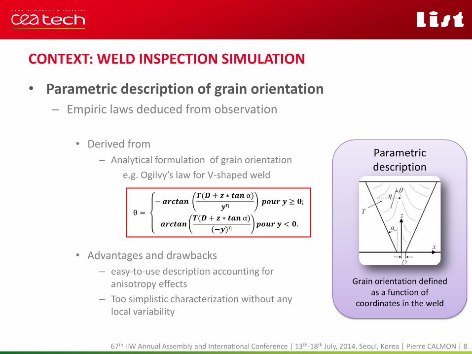
• Parametric description of grain orientation – Empiric laws deduced from observation
• Derived from
– Analytical formulation of grain orientation
e.g. Ogilvy’s law for V-shaped weld
• Advantages and drawbacks
– easy-to-use description accounting for anisotropy effects
– Too simplistic characterization without any local variability
67th IIW Annual Assembly and International Conference | 13th-18th July, 2014, Seoul, Korea | Pierre CALMON | 8
Parametric description
Grain orientation defined as a function of
coordinates in the weld
θ =
− 𝒂𝒓𝒄𝒕𝒂𝒏 𝑻(𝑫 + 𝒛 ∗ 𝒕𝒂𝒏 α)
𝒚η 𝒑𝒐𝒖𝒓 𝒚 ≥ 𝟎;
𝒂𝒓𝒄𝒕𝒂𝒏𝑻(𝑫 + 𝒛 ∗ 𝒕𝒂𝒏 α)
(−𝒚)η𝒑𝒐𝒖𝒓 𝒚 < 𝟎.

CONTEXT: WELD INSPECTION SIMULATION
• Usual modelling tools for NDT applications – Finite Element Method (FEM) or Finite Difference Method (FDM)
• Industrial FEM codes: ABAQUS, ANSYS, COMSOL…
• FDM academic codes: EFIT, SimSonic, ACEL-NDT,…
• ATHENA FEM code (EDF R&D) specifically dedicated to NDT inspections in welds using fictitious domain method for defects of complex geometry
– Ray-based method with paraxial approximation
• Dynamic Ray Tracing (model used in CIVA)
• Gaussian Beam
• Gaussian Wave Packet
67th IIW Annual Assembly and International Conference | 13th-18th July, 2014, Seoul, Korea | Pierre CALMON | 9
FE calculation zone
Probe
Defect
Weld

MODELLING OF WELD INSPECTION WITH THE CIVA SOFTWARE
67th IIW Annual Assembly and International Conference | Pierre CALMON | 10

MODELLING OF WELD INSPECTION IN CIVA
• Beam simulation with piecewise description of weld in CIVA – DRT method manages only piecewise homogeneous descriptions in the
current CIVA version • Propagation: in each homogeneous domain ray tracing is a straight line in a constant
direction of energy
• Reflexion/Refraction: Snell’s law is applied on the interface between 2 homogeneous domains
– Good agreement with other FE codes if some conditions are met:
• domains characteristic lengths >> wavelength
• small contrast of impedance between adjacent domains
67th IIW Annual Assembly and International Conference | 13th-18th July, 2014, Seoul, Korea | Pierre CALMON | 11
12.7 mm L0 contact probe 2.25 MHz
32
mm
λ ≈ 2,5mm
FEM Athena (EDF) Chassignole PhD Thesis

MODELLING OF WELD INSPECTION IN CIVA
• Illustration of ray model limits for a piecewise description – Comparison for 2 different descriptions
– Comparison of the results with hybrid Finite Element Code (CIVA/ATHENA)
67th IIW Annual Assembly and International Conference | 13th-18th July, 2014, Seoul, Korea | Pierre CALMON | 12
3λ
Weld #1 respecting the ray theory validity condition
Side drilled hole (located at the same depth)
λ
Weld #2 not respecting the ray theory validity condition
Contrast of impedance equivalent in the two
descriptions
Finite Element Box
Incident field computed with CIVA

MODELLING OF WELD INSPECTION IN CIVA
• Illustration of ray model limits for a piecewise description – Side-drilled hole echo simulations for weld #1 (dimensions around 3λ)
Good agreement between FE model and the DRT model
– Side-drilled hole echo simulations for weld #2 (dimensions around λ)
Discrepancies between FE model and the DRT model (amplitude and position)
67th IIW Annual Assembly and International Conference | 13th-18th July, 2014, Seoul, Korea | Pierre CALMON | 13
3λ Hybrid Code Athena/CIVA
Scanning position
DRT model in CIVA
Scanning position
0.2dB
- CIVA - Athena
Time
λ Hybrid Code Athena/CIVA
Scanning position
DRT model in CIVA
Scanning position
6.3dB
- CIVA - Athena
Time

MODELLING OF WELD INSPECTION IN CIVA
• From a piecewise description of weld to a equivalent material with smoothly inhomogeneous properties – Drawbacks of the piecewise description
• Interfaces generate unrealistic artefacts and wave mode conversions
• Penalizing description for the ray model: simulation variations with respect to domain geometry definitions
• Inapplicable or too approximate description for a lot of weld types
– Advantages of a equivalent smoothly inhomogeneous material
• Can be deduced directly from parametric description or from mapping description with smoothing filtering process
• Well-adapted and generic approach for a lot of weld types
• Modelling an average behavior of the coherent wave front used for the inspection
67th IIW Annual Assembly and International Conference | 13th-18th July, 2014, Seoul, Korea | Pierre CALMON | 14
Extension of DRT model for smoothly inhomogeneous anisotropic material in next CIVA version

MODELLING OF WELD INSPECTION IN CIVA
• DRT model in smoothly inhomogeneous anisotropic material – Evaluation of ray-paths and travel time
• Deduced from Eikonal equation
Differential equation to solve, called axial ray system, defining the ray trajectory
– Computation of ray amplitude
• Deduced from the Transport equation in a ray tube (energy conservation) assuming paraxial approximation
Another differential equation to solve, called paraxial ray system, defining the evolution of the ray tube associated to the axial ray trajectory
67th IIW Annual Assembly and International Conference | 13th-18th July, 2014, Seoul, Korea | Pierre CALMON | 15
Polarization vector
Energy velocity vector position of the ray
slowness of the ray
with 𝑎𝑖𝑗𝑘𝑙 = 𝜌−1𝑐𝑖𝑗𝑘𝑙
V. Cerveny, Seismic Ray Theory, Cambridge University Press, 2001 A. Gardahaut et al., QNDE, 2013
𝑑𝛿𝑥𝑖𝑑𝑇
= 𝐴𝑖𝑗𝛿𝑥𝑗 + 𝐵𝑖𝑗𝛿𝑝𝑗
𝑑𝛿𝑝𝑖𝑑𝑇
= 𝐶𝑖𝑗𝛿𝑥𝑗 + 𝐷𝑖𝑗𝛿𝑝𝑗

MODELLING OF WELD INSPECTION IN CIVA
• DRT model in smoothly inhomogeneous anisotropic material – Higher computation cost than for straight line ray tracing (piecewise
description)
• Iterative time step procedures to solve differential equations
Euler or RK4 schemes performed with adaptive step
• Examples of ray tracing in the CIVA scene
67th IIW Annual Assembly and International Conference | 13th-18th July, 2014, Seoul, Korea | Pierre CALMON | 16
L45 case T45 case
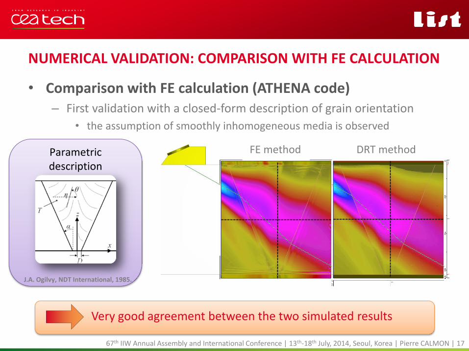
NUMERICAL VALIDATION: COMPARISON WITH FE CALCULATION
• Comparison with FE calculation (ATHENA code) – First validation with a closed-form description of grain orientation
• the assumption of smoothly inhomogeneous media is observed
67th IIW Annual Assembly and International Conference | 13th-18th July, 2014, Seoul, Korea | Pierre CALMON | 17
Very good agreement between the two simulated results
Hybrid Finite Element Code Dynamic Ray Tracing
-- Hybrid Finite Element Code
-- Dynamic Ray Tracing
FE method DRT method Parametric description
J.A. Ogilvy, NDT International, 1985.

NUMERICAL VALIDATION: COMPARISON WITH FE CALCULATION
• Comparison with FE calculation (ATHENA code) – Validation with a mapping description of the weld
• assumption of smoothly inhomogeneous media assumed following a spline interpolation on the grid
67th IIW Annual Assembly and International Conference | 13th-18th July, 2014, Seoul, Korea | Pierre CALMON | 18
Mapping description
2x2 mm mapping of grain orientation macrography of the weld
Image processing
interpolation

Differences below 1.5 dB between the two models
FE method DRT method
FE method DRT method
FE method DRT method
Mapping description
67th IIW Annual Assembly and International Conference | 13th-18th July, 2014, Seoul, Korea | Pierre CALMON | 19
NUMERICAL VALIDATION: COMPARISON WITH FE CALCULATION • Comparison with FE calculation (ATHENA code)
– Validation with a mapping description of the weld

EXPERIMENTAL COMPARISONS
• Characteristics of the inspected welded mock-up – Specific mock-up with calibrated flaws (SDH and notches)
– SMAW weld realized in vertical position
• disorientation of the fiber axis along the welding direction (about 18°)
(XZ) inspection plane is not a plane of symmetry (3D case)
SDH1/SDH2 1.5 mm N1/N2/N3 10 mm height N3 located into the weld
67th IIW Annual Assembly and International Conference | 13th-18th July, 2014, Seoul, Korea | Pierre CALMON | 20
MOSAICS Project

EXPERIMENTAL COMPARISONS
• Properties used for simulation – Anisotropic elastic properties obtained with characterization process
• Anisotropic damping properties (2D description only)
(N. Alaoui Ismaili et al., QNDE, 2013)
MOSAICS Project
67th IIW Annual Assembly and International Conference | 13th-18th July, 2014, Seoul, Korea | Pierre CALMON | 21

EXPERIMENTAL COMPARISONS
• Comparison with L45 inspection at 2MHz – Experimental CScan
IP1
IP2
IP3
SDH1 echoes SDH2 echoes
N1 echoes N2 echoes
N3 echoes
Analysis of comparisons in these 3 inspections planes
MOSAICS Project
67th IIW Annual Assembly and International Conference | 13th-18th July, 2014, Seoul, Korea | Pierre CALMON | 22

EXPERIMENTAL COMPARISONS
• Study of SDH echoes:
67th IIW Annual Assembly and International Conference | 13th-18th July, 2014, Seoul, Korea | Pierre CALMON | 23
very good agreement of direct echoes before and after passing through the welding joint
SDH2 :-11.5dB
SDH2 :-11 dB
SDH1 : ref.
SDH1 : ref.
DRT model in CIVA Experimental data
Exp
erim
ent
DR
T m
od
el
MOSAICS Project

EXPERIMENTAL COMPARISONS
• Study of N1 and N2 echoes:
67th IIW Annual Assembly and International Conference | 13th-18th July, 2014, Seoul, Korea | Pierre CALMON | 24
N1 : corner LL
DRT model in CIVA Experimental data
Exp
erim
ent
DR
T m
od
el
N1 : corner LLT
N1 : corner TT N2 : corner LL
N1 : corner LL N1 : corner LLT
N1 : corner TT
N2 : corner LL
simulated mixed corner echo (LLT) of N1 notch overestimated with respect to other corner echoes
good agreement especially for the LL corner echoes
MOSAICS Project

DRT model in CIVA Experimental data
Exp
erim
ent
DR
T m
od
el
N3 : corner LL N3 : corner LLT
N3 : corner LL
EXPERIMENTAL COMPARISONS
• Study of N3 echoes located into the weld:
67th IIW Annual Assembly and International Conference | 13th-18th July, 2014, Seoul, Korea | Pierre CALMON | 25
worse result: - 4 dB discrepancy for the LL echo - mixed corner echo not simulated
weld seam description not enough precise with regards to UT in this area
MOSAICS Project

CONCLUSION AND PERSPECTIVES
67th IIW Annual Assembly and International Conference | Pierre CALMON | 26
CONCLUSIONS
• Evolution of modelling in CIVA to perform NDT in welds – using a ray-based approximation on a smoothly inhomogeneous
anisotropic medium
– GUI tools introduced in CIVA to manage such description (parametric or mapping descriptions)
– Manage 3D configurations in terms of probe, defect and material with a more realistic descriptions of welding joint
• Validations: – Numerical validation: P-wave field successfully compared with FE code
with a closed-form expression and a mapping description provided from a macrograph image processing
– Comparisons with experimental acquisitions:
• good agreement when flaws located outside the weld in the base metal
• discrepancies observed when the notch is located at the weld bead
67th IIW Annual Assembly and International Conference | 13th-18th July, 2014, Seoul, Korea | Pierre CALMON | 27

PERSPECTIVES
• Weld description: – facilitate the procedures for defining the properties of welds
• Mechanical properties and grain properties in weld
Analysis automated tools of macrography
Import of descriptions provided by numerical simulation of welding process
• Geometry of weld
Set of predefined geometric description of weld
67th IIW Annual Assembly and International Conference | 13th-18th July, 2014, Seoul, Korea | Pierre CALMON | 28
PERSPECTIVES
• Ray based modelling in CIVA: – qT modes modelling in progress for inhomogeneous anisotropic
medium
– handle with 3D anisotropy of the wave attenuation
– improve the computation time and the numerical precision
– investigate the sensitivity of the model according to the descriptions of welds obtained by macrography or simulation codes
– Model more accurately the interaction of the ultrasonic wave with the polycrystalline structure of welds;
• determine the anisotropic behavior of the attenuation and wave velocity according to the wavefront direction
67th IIW Annual Assembly and International Conference | 13th-18th July, 2014, Seoul, Korea | Pierre CALMON | 29