utah state implementation plan section x vehicle
TRANSCRIPT
UTAH STATE IMPLEMENTATION PLAN
SECTION X
VEHICLE INSPECTION
AND MAINTENANCE PROGRAM
PART D
UTAH COUNTY
Adopted by the Utah Air Quality Board
December 5, 2012

Section X Part D, page i
Table of Contents
1. Applicability ............................................................................................................................................................. 1 2. Summary of Utah County I/M Program ..................................................................................................................... 1 3. I/M SIP implementation ............................................................................................................................................. 3
Section X Part D, page ii
SECTION X, PART D
UTAH COUNTY
Appendices
1 Vehicle Emissions Inspection/Maintenance Program, Ordinance 2011-42, revised
November 22, 2011.
2 Provo I/M Ordinance 1994-106, December 12, 1994
3 Audit Policies

Section X Part D, page 1
UTAH STATE IMPLEMENTATION PLAN
SECTION X
AUTOMOTIVE INSPECTION AND MAINTENANCE (I/M) PROGRAM
PART D
UTAH COUNTY
1. Applicability
Utah County I/M program requirements: Provo City was designated nonattainment for the
carbon monoxide (CO) National Ambient Air Quality Standards (NAAQS) on January 6, 1992
(56 FR 56846, November 6, 1991) and was classified as a "moderate" area. The Provo City CO
nonattainment area was redesignated to attainment for the CO NAAQS on January 3, 2006 (70
FR 66264, November 2, 2005).
Utah was previously required by Sections 182 and 187 of the Clean Air Act to implement and
maintain an I/M program in Utah County that met the minimum requirements of 40 CFR Part 51
Subpart S and that was at least as effective as the EPA's Basic Performance Standard as specified
in 40 CFR 51.352. However, the Basic Performance Standard requirement is no longer
applicable as the nonattainment area in Utah County has been redesignated to attainment /
maintenance for the CO NAAQS. Parts A and D of Section X, together with the referenced
appendices, continue to demonstrate compliance with the 40 CFR Part 51 provisions for
Inspection and Maintenance Program Requirements for Utah County and produce mobile source
emission reductions that are sufficient to demonstrate continued maintenance of the CO NAAQS.
In addition, the Utah County I/M program is a control measure to attain and maintain EPA's
particulate NAAQS in Utah County.
Provo City ordinance: In addition to the Utah County ordinance, Provo City ordinance requires
that the vehicles operated by people staying in Provo for more than sixty days be inspected and
repaired as specified in the Utah County I/M ordinance regardless of where the vehicle is
registered. These ordinances are provided in Section X, Part D, Appendix 1 and 2.
2. Summary of Utah County I/M Program
Below is a summary of Utah County’s I/M program. Section X, Part D Appendices 1 – 3 contain
the essential documents for Utah County’s I/M program.
Network Type: Utah County’s I/M program is a decentralized, test-and-repair network, as
approved by EPA on November 2, 2005 (70 FR 66264).
Test Convenience: There are approximately 200 permitted I/M stations within Utah
County. Specific operating hours are not specified by the county. Some stations that test

Draft—August 21, 2012
Section X Part D, page 2
and/or service only one type of vehicle are permitted. There are also government and
private fleet permitted stations that are not open to the public.
Subject fleet: All model year 1968 and newer vehicles registered or principally-operated
in Utah are subject to the I/M program except for exempt vehicles.
Test frequency: Vehicles less than two years old as of January 1 on any given year are
exempt from an emissions inspection. Vehicles two years old and less than six years old
as of January 1 on any given year are inspected every other year as per Utah Code 41-6a-
1642(6). All vehicles six years old and older as of January 1 on any given year are
inspected annually.
Station/inspector Audits: Utah County’s I/M program will regularly audit all permitted
I/M inspectors and stations to ensure compliance with county I/M ordinances and
policies. Particular attention will be given to identifying and correcting any fraud or
incompetence with respect to vehicle emissions inspections. Compliance with
recordkeeping, document security, analyzer maintenance, and program security
requirements will be scrutinized. Utah County I/M program will have an active covert
compliance program to minimize potential fraudulent testing. Utah county audit policy is
provided in Appendix 3 of this Part of Section X.
Waivers: Utah County’s I/M program may issue waivers under limited circumstances.
The wavier procedure can be found in Utah County’s I/M ordinance provided in
Appendix 1. Utah County will take corrective action as needed to maintain a maximum
waiver rate of 5% of the initially failed vehicles, or the Utah Air Quality Board will revise
the SIP and emission reductions claimed based on the actual waiver rate. The procedure
for issuing waivers is specified in Utah County’s I/M ordinance provided in Appendix 1
of this Part of the SIP and meets the minimum waiver issuance criteria specified in 40
CFR Subparts 51.360.
Test Equipment: Specifications for Utah County’s emission analyzer and its I/M test
procedures, standards and analyzers are provided in Utah County’s I/M ordinance
provided in Appendix 1. Test equipment and procedure were developed according to
good engineering practices to ensure test accuracy. Analyzer calibration specifications
and emissions test procedures meet the minimum standards established in Appendix A of
the EPA's I/M Guidance Program Requirements, 40 CFR Part 51 Subpart S.

Draft—August 21, 2012
Section X Part D, page 3
Test Procedures:
The following vehicles are subject to an OBD II inspection:
o 1996 and newer light duty vehicles1 and
o 2008 and newer medium duty vehicles2
The following vehicles are subject to a two-speed idle test that is compatible with
Section VI (Preconditioned Two Speed Idle Test) in Appendix B of the EPA I/M
Guidance Program Requirements, 40 CFR 51, Subpart S:
o 1995 and older vehicles,
o 1996 to 2007 medium and heavy duty vehicles3 and
o 2008 and newer heavy duty vehicles.
3. I/M SIP implementation
1 Light duty vehicles have a Gross Vehicle Weight of 8500 lbs or less.
2 Medium duty vehicles have a Gross Vehicle Weight greater than 8500 lbs but less than 14,000 lbs 3 Heavy Duty vehicles have a Gross Vehicle Weight greater 14,000 lbs
The I/M program ordinances, policies, procedures, and activities specified in this I/M SIP
revision have been implemented and shall continue until a maintenance plan without an I/M
program is approved by EPA in accordance with Section 175 of the Clean Air Act as amended.


REVISED UTAH 2000 EMISSION INSPECTION SYSTEM
SPECIFICATIONS
January 2000

1-2
UTAH 2000 TWO SPEED IDLE & OBD II SPECIFICATION SECTION 1. INTRODUCTION 1.1 BACKGROUND INFORMATION
The County has adopted Regulation __XXX_____ that changes the emission test used in the inspection/maintenance (I/M) program from that specified in UTAH-91. The previously required two-speed idle (TSI) test will be modified to conform to BAR-97 TSI standards, a series of enhanced two speed idle tests. Vehicle model years 1995 and older will now be subject to the enhanced TSI testing. In general, vehicles 1996 and newer will use an OBD II test procedure. This document details the specifications for emission test systems to perform the two mode TSI, OBD II, safety, and gas cap tests.
1.2 COMMON TERMS AND DEFINITIONS
This document hence forth shall use the term "the County" to refer to the Counties of Davis, Utah and Weber as a single entity for the purposes of this specification. The following words may have been used interchangeably within this document:
For the physical cabinet and hardware; Analyzer Software UTAH 2000 TAS-Test Analyzer System EIS Unit Instrument
For the Contractor; Contractor Manufacturer 1.3 ELECTRONIC TRANSMISSION 1.3.1 Electronic Data Transmission (EDT) Overview
A required component of the enhanced program is the electronic transmission of data about the vehicle under test and its test results. Electronic Data Transmission (EDT) is the name that the County has given to the electronic network that enables the UTAH 2000 to automatically connect to the County's centralized Vehicle Information Database (HOST) via the modem and dial-up connection.
a) Mandatory EDT Service:
In order to comply with the EDT mandate, each inspection station shall obtain and maintain EDT services through the County's designated EDT contractor. The following criteria shall be met before an EIS is used for I/M test certification: (1) the EIS shall be connected to, and shall be fully functional with the EDT service and (2) the EIS shall maintain, and be operational with the most currently approved software and hardware updates. However, the UTAH 2000 units shall

1-3
be capable of properly operating independently of the EDT service in the event the EDT services are not functioning for program start-up.
NOTE: The electronic certificate feature is required for authorization of certificate
numbers. The UTAH 2000 will also have a similar function for bar code entry of certificates. The specification describes a manual method of achieving the same function. At least the manual method must exist at program start-up.
b) Charges for EDT Services: Inspection stations must maintain EDT service in accordance with the terms specified by the
contract between the County and the EDT contractor.
c) Communication Protocol The Contractor will be required to finalize development of a communications protocol for the transmission of data to and from the HOST. The Contractor shall provide the algorithm/procedures or software that facilitates communication between the UTAH 2000 analyzers and the EDT host computers. d) EDT Host Computer System (HCS)
The EIS will be required to interface to the EDT network host system. The HCS will run on a Microsoft Windows NT network. The transmitted data files will be stored in a Microsoft SQL Server database. Each analyzer must be able to Communicate to the Windows NT 4.0 Server via a secured/encrypted method. The County prior to implementation must approve the proposed method. All transactions with the HCS will be accomplished using the approved method only.
1.3.2 Form, Manner and Frequency of Data Transmittals for ET a) Form: For each inspection, the data transmittal shall consist of the vehicle's test
information and, when required, repair information, safety information, audit data, tamper data, calibration data, and lockout information.
b) Manner: The manner of the data transmittal shall be using the method approved
by the County and subsequently adopted into the UTAH 2000 specifications. The UTAH 2000 must be maintained to ensure proper operation and shall be connected to a fully operational connection during all times of operation.
c) Frequency: The data shall be transmitted for inspection and shall include one
transmission per scheduled time period. If the initial contact results in no match being found, an additional transmission may be required.
1.4 TAMPER RESISTANCE
Since the proposed EIS must be California BAR-97 Approved, the controlled access design shall be that method used by the manufacturer during California BAR-97 Approval. Measures for securing any additional hardware not included in the California BAR-97 Approval shall be submitted for approval by the County. Analyzer operators,

1-4
the County field representatives, Contractor's representatives, and manufacturer's representatives shall be prevented from creating or changing any test results, the County programs or the County data files contained in the EIS as called for in this specification. The EIS' shall utilize special BIOS, partitions (or equivalent approved by the County), as well as other appropriate software and hardware provisions deemed necessary by the County to protect the I/M files and programs. File and program protection may consist of mechanical systems in combination with electronic/software systems. The protection features shall prevent access to the secured disk drives and portions of the hard disk containing I/M programs and test data. The "control" key, or its functional equivalent giving access to the operating system (OS), shall not be activated except through the use of a special password algorithm securing the EIS' service-related page(s) and menu(s). The County shall approve the password algorithm at the time of certification testing. The Contractor may propose other security or protection alternatives, such as more sophisticated BIOS limitations and LPT port key, for approval by the County.
In addition, the emission analyzer and the sampling system shall be made tamper-resistant. As a minimum, the manufacturer shall develop tamper-resistant features to prevent unauthorized access through the cabinet. Micro-switches, keyed locks, software-controlled locks, and software algorithms requiring the use of an access code shall all be utilized where appropriate. Access codes for the County functions shall be changed daily based on an algorithm proposed by the Contractor and provided to the County. Service access codes shall be changed daily based on a unique algorithm provided by the Contractor. Algorithms must be changeable at the request of the County as part of a software update. Manufacturers must utilize electronic monitoring on the doors securing the floppy disk drives. The following examples illustrate ineffective, and therefore unacceptable, security measures: A mercury switch would not be effective if the analyzer can be tipped over to one side to trigger the switch.
A software-controlled solenoid sensor shall be used on the secured floppy drive door of all UTAH 2000 units. This sensor must be used in conjunction with any key or combination lock. The sensor shall be controlled by the EIS software, allowing the unlatching of the doors in response to authorized requests from the County Menu, always maintaining the appropriate levels of security. All UTAH 2000 EIS units shall have sensors, such as micro-switches, to detect the “open/closed” state of the doors, as well as other secured areas of the EIS. The EIS shall monitor these sensors and shall define an inappropriate state as a tamper.
Manufacturers may offer analyzers with additional disk drives that can run optional software application programs. However, the optional disk drives shall be secured from the BIOS, operating system and all other I/M related programs and test data (or equivalent acceptable to the County). If tampering occurs, a software lockout algorithm shall be activated which aborts any existing test sequence and prevents further I/M testing until the lockout is cleared by a the County field representative (or other representatives authorized by the County). In addition, manufacturers must describe, to the County's satisfaction, what security measures will be taken to prevent the unauthorized use of access codes, keys and combinations to the secured areas of the analyzer under each of the following circumstances:

1-5
1. Tampering has occurred. 2. A manufacturer's service technician quits or is fired.
3. 3. A combination, key or critical access code is obtained by an
unauthorized person(s) such as an inspection technician. The County field representatives or other representatives authorized by the County may have access to the analyzer's OS or be able to modify files on the hard disk. At no point shall technicians have access to either the OS or the BIOS.
The use of micro-switches to detect unauthorized entry is acceptable. However, unauthorized access to the secured areas of the analyzer shall be detected even when the power is off. The analyzer shall record the type and location of each tamper. The tamper attempts shall be recorded in a tamper file which includes the date of the tamper-caused lockout, the type and location of the lockout, the date the lockout was cleared and who it was cleared by (the County or manufacturer's service representative). The specific tamper type and location shall only be accessible through the County Menu - LOCKOUT EIS function.
The lockout system shall be designed so that it can be activated by a the County field representative from the County Menu. Only the County field representatives (or other representatives authorized by the County) may remove lockouts put in place from the County Menu. Manufacturers shall develop a system by which their service technicians shall be prevented, by some method approved by the County, from clearing the County installed lockouts. In particular, the following policies shall apply to the manufacturers' field representatives:
1. They shall not be capable of clearing a County -installed lockout; 2. They shall not be capable of clearing a lockout due to a requirement for a
three-day gas calibration/leak check; 3. They shall not be capable to add, delete or modify Station or Technician
license number; 4. They shall not be capable of altering the calibration gas values; 5. They shall not clear a lockout when there is evidence of physical
tampering. Furthermore, they shall report this or any other type of lockout to the County field office by the end of the next working day after discovering the lockout.
The access codes used by the manufacturer's service representatives shall be changed automatically by the EIS on a daily basis. The algorithm must not be available to manufacturer's field service personnel. The daily service access codes may only be given to authorized field service representatives and may not be provided more than one week in advance. The tamper resistance features shall be designed so that software programs, especially those that deal with repair and diagnosis of vehicles, can be added at a later date.

1-6
Optional software packages supplied by the manufacturer shall: 1) not interfere with the normal operation of the I/M inspection and testing software; 2) not compromise the tamper-resistance of the analyzer or software (such as giving the technicians access to the OS); and 3) be approved by the County before they are delivered or installed in any UTAH 2000 analyzers.
Access to and from all required and mandatory-option programs shall be "seamless." These programs shall be accessed from the Main Menu or a submenu, and, when exited, shall return directly to the menu or submenu from which they were accessed, without requiring the EIS to reboot.
1.5 ORGANIZATION OF SPECIFICATION
This document provides the specifications for the UTAH 2000 equipment and procedures to be used for performing inspections required by the County Regulation ______XXX_______
Section 1 This section is an introduction, providing background about emission testing equipment, summarizing enhancements recently added to the UTAH 2000. System security and integrity are also included in this section.
Section 2 This section gives the specifications, including
performance standards, for all test-related hardware such as the computer, the analyzer, the OBD II tester, the fuel cap tester, the analyzer cabinet, and the bar code scanner.
Section 3 This section describes in detail the software specification,
including data storage; the form, manner and frequency of electronic transmission including transmission of test, calibration and vehicle records, sequences and procedures for performing required tests.
Section 4 This section describes in detail the requirements for the
Vehicle Information Database (HOST) hardware and software functions.
Section 5 This section describes in detail the requirements for Warranty, Service and Documentation that must be adhered to in order to provide and guarantee a satisfactory level of protection for the UTAH 2000 customers.
The Appendices contain items referred to in the Specification such as the emissions standards table and the information that must be transmitted to and from the HOST, as well as highly technical and strictly confidential items.

2-1
SECTION 2 HARDWARE SPECIFICATIONS 2.1. OVERVIEW
Section 2 discusses the hardware performance requirements (and design requirements where necessary) for the UTAH 2000 Emission Inspection System (EIS) needed to perform emissions testing on the vehicles registered in the participating counties.
This section covers the computer and its peripherals, the emissions analytical instrument and its sample conditioning system, OBD II hardware, the cabinet and the hardware aspects of its security, bar code scanning, engine speed measurement, and other equipment.
The UTAH 2000 units must comprise of an IBM-compatible personal computer (PC) with a printer , a modem and software and hardware to perform both two-speed idle and OBD II testing; a five-gas analyzer and sample conditioning system; zero and calibration gases; a bar code reader; a fuel cap tester; a tachometer, an opacity measurement system (optional) and a cabinet.
2.1.1 Computer/Peripheral Compatibility Computers shall be IBM-PC-compatible. They shall be able to reliably read and write IBM-compatible 1.44Mb 3.5" diskettes.
Systems must be capable of producing graphic output on CRT displays and printers. The computer and printer shall be capable of printing graphics and text displayed on CRT.
Systems must be capable of communicating with computers, specifically the HOST, using modems and a dial-up connection. The power supply must have the potential to handle at least 100 watts of additional upgrade devices.
2.2 GENERAL REQUIREMENTS 2.2.1 Availability of Circuitry
All components including circuit board and integrated circuits used in the EIS shall be types and brands that are presently in common usage. Custom ROM programs developed by the manufacturer for building the analyzer are allowed. Deviations may be allowed upon approval by the County.
2.2.2 Clock/Calendar
The EIS shall have a real time clock/calendar which shall make available the current date and time. Both time and date shall be in standard IBM PC format and used to set the computer's date and time on power up.
The EIS shall store the date and time in the DateofTest, TestStartTime and TestEndTime fields (or similarly named fields) of the EIS, Repair, and Safety records.

2-2
The communication software shall reset the current EIS date/time settings each time contact is made with the HOST except during communication diagnostics. The EIS clock shall be reset to the HOST clock at the beginning of each test. If the HOST determines that the EIS clock is not keeping correct time, the HOST shall set a lockout and a message shall be displayed indicating that service is required.
Resetting the clock after a lockout shall require controlled access available only to the County Representatives and the manufacturer's service technician. The access mechanism or procedures shall be approved by the County.
The analyzer clock/calendar shall be equipped with a battery backup feature that has a battery with at least a five-year expected life. The calendar shall be capable of handling the year roll-over from 1999 to 2000.
2.2.3 Data and File Transfer
All vehicle test, calibration, tamper and other required information shall be capable of being transferred from the EIS to the HOST:
a) Via an IBM PC compatible modem (located inside the cabinet) and connection to
a telephone line, electronically receiving and/or transmitting data from the HOST whenever the EIS connects to the HOST, and
b) By use of the standard 3.5" IBM 1.44Mb compatible floppy disk.
2.2.4 OBD II
The EIS shall have a port to connect to any OBD II SAE Standardized Link. Hardware must be completely enclosed in EIS cabinet, less the cable to vehicle. The link shall enable the EIS to access vehicle readiness status, fault codes, MIL Request Status and engine RPM. The EIS must also have the ability to clear fault codes for all OBD II equipped vehicles. For certification purposes, the County requires a description of the OBD II hardware and requires the hardware to undergo a series of tests to determine accuracy.
2.2.5 Analyzer Compatibility
The EIS shall be compatible with all types of automotive service operating environments. The analyzer shall operate under the conditions and performance requirements of this specification.
2.2.6 Testing Throughput Capability
The emissions analyzer shall be designed so that it is capable of performing at least 10 tests per hour for eight consecutive hours without experiencing excessive hang-up or other deleterious effects.

2-3
2.3 COMPUTERS & PERIPHERAL REQUIREMENTS
The EIS functions shall be controlled by an IBM PC-compatible computer. Each EIS must include the hardware and software needed to perform all functions required by this specification. The computer shall be capable of at least the following tasks:
1. Collect and record HC, CO, CO2, and O2, (NO upgrade) readings at a rate
of once per second, at a minimum,
2. Monitor and clear OBD II functions,
3. Transmit test and other records to the HOST,
4. Read and interpret bar code labels from DMV registration documents, technician identification cards, calibration gas bottles, testing facility and technician licenses, referee labels, VIN and VEC labels,
5. Read data from compact discs (CD),
6. Provide storage for archived test and graphic files,
7. Test vehicle gas caps, 8. Recall as well as provide VIR reprint capability for emission test records
and repair records, 9. Access engine RPM,
10. Interface with an optional partial-flow opacity-measuring device, display
and record to the test record,
11. Demonstrate Year 2000 compliance.
The County reserves the right to add additional programs and functional performance requirements, up to the technical limits of the hardware, to improve the inspection and maintenance program.
Manufacturers may offer analyzers with additional disk drives that can run optional software/hardware application programs; however, the computer shall not be bootable from any additional drive, nor shall any program run from one of these drives have access to the computer’s operating system. Programs run from an additional drive shall not be capable of interfering with, modifying, corrupting or interrupting any inspection-related program, procedure, or file.
2.3.1 Minimum Required Microcomputer Configuration
2-4
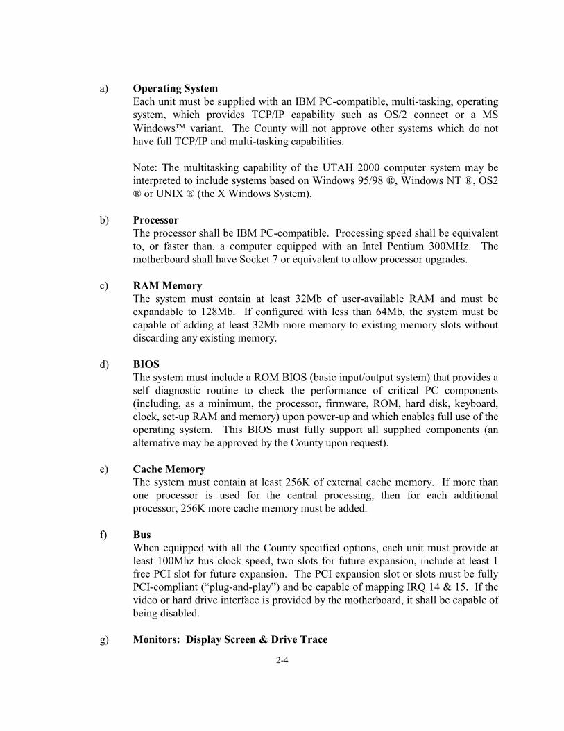
a) Operating System
Each unit must be supplied with an IBM PC-compatible, multi-tasking, operating system, which provides TCP/IP capability such as OS/2 connect or a MS Windows variant. The County will not approve other systems which do not have full TCP/IP and multi-tasking capabilities. Note: The multitasking capability of the UTAH 2000 computer system may be interpreted to include systems based on Windows 95/98 ®, Windows NT ®, OS2 ® or UNIX ® (the X Windows System).
b) Processor
The processor shall be IBM PC-compatible. Processing speed shall be equivalent to, or faster than, a computer equipped with an Intel Pentium 300MHz. The motherboard shall have Socket 7 or equivalent to allow processor upgrades.
c) RAM Memory
The system must contain at least 32Mb of user-available RAM and must be expandable to 128Mb. If configured with less than 64Mb, the system must be capable of adding at least 32Mb more memory to existing memory slots without discarding any existing memory.
d) BIOS
The system must include a ROM BIOS (basic input/output system) that provides a self diagnostic routine to check the performance of critical PC components (including, as a minimum, the processor, firmware, ROM, hard disk, keyboard, clock, set-up RAM and memory) upon power-up and which enables full use of the operating system. This BIOS must fully support all supplied components (an alternative may be approved by the County upon request).
e) Cache Memory
The system must contain at least 256K of external cache memory. If more than one processor is used for the central processing, then for each additional processor, 256K more cache memory must be added.
f) Bus
When equipped with all the County specified options, each unit must provide at least 100Mhz bus clock speed, two slots for future expansion, include at least 1 free PCI slot for future expansion. The PCI expansion slot or slots must be fully PCI-compliant (“plug-and-play”) and be capable of mapping IRQ 14 & 15. If the video or hard drive interface is provided by the motherboard, it shall be capable of being disabled.
g) Monitors: Display Screen & Drive Trace

2-5
The active screen area must be in color, of .28 dot pitch or less, and measure at least 17" diagonally. The monitor must be capable of non-interlaced resolution up to 1024 X 768. The display must interface with a color graphics adapter fully compatible with the IBM SVGA color graphics adapter. This interface must be capable of operating in non-interlaced modes up to a resolution of 1024 X 768 while emulating 64K colors or more. The video adapter must be equipped with a 64-bit accelerator chip (or better) to increase its video processing speed and must be PCI bus-compliant. The video adapter must be easily upgradable to at least 4Mb and must be already equipped with 2Mb.
The above specifications do not apply to a second portable monitor that may be provided for the driver. However, this monitor must display all warnings and information required to perform the driving portion of the test (RPM, drive trace, etc.). This second monitor is subject to the County approval.
h) Floppy Disk
One 1.44Mb floppy drive is required. The floppy drives must have an external door protecting them from contamination (dust). The analyzer's cooling fan (if equipped) shall not create a negative pressure in the case unless the floppy drive(s) are sealed to prevent this negative pressure from drawing dust into the drive. The secured floppy disk shall be designated the "A" drive.
i) Compact Disc (CD)
Each analyzer must be equipped with one CD ROM drive. The disk drive must be protected from contamination in the shop environment. The CD ROM drive shall be capable of reading CD ROMs that are formatted per ISO 9660. The minimum acceptable sustained transfer rate is 600 kilobytes per second with a minimum acceptable average random access time of 225ms and must be multimedia and photo CD compatible as a minimum. A means for providing security to prevent unauthorized access to lower level system functions shall be submitted by the manufacturer for County approval.
j) Hard Disk
Each unit must come with at least 4 gigabytes of usable formatted uncompressed hard disk storage. The vendor must leave at least 2 gigabytes of usable storage for the County. Second-by-second data, emission inspection data (including graphics) and vehicle data will be stored in the County storage area. The system shall warn the technician with a screen prompt when the hard disk is within 10% of being full in any of the allotted storage areas. The hard disk is to be self-parking, shock mounted, and able to operate reliably in the expected hostile garage environment. The hard disk must also include a County-approved method of limiting logical access to the County data and programs. The hard drive's minimum acceptable burst transfer (external transfer) shall be 7,000 kilobytes per second. The hard drive's minimum acceptable sustained transfer (internal
2-6
transfer) shall be 2,000 kilobytes per second. The minimum acceptable average random access time shall be 14ms. No software cache can be used when measuring transfer rate or access times.
k) Hard Disk Interface
The hard disk interface must be PCI bus-compliant and use enhanced IDE Mode 4 (or better) or Fast SCSI-2 (or better) or alternative approved by the County. The hard disk interface must be capable of maintaining a minimum transfer rate of 8,000 kilobytes per second with all peripherals installed (including options).
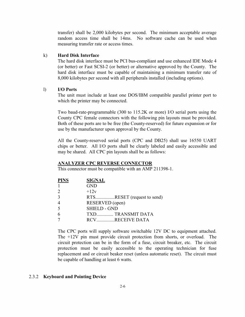
l) I/O Ports
The unit must include at least one DOS/IBM compatible parallel printer port to which the printer may be connected.
Two baud-rate-programmable (300 to 115.2K or more) I/O serial ports using the County CPC female connectors with the following pin layouts must be provided. Both of these ports are to be free (the County-reserved) for future expansion or for use by the manufacturer upon approval by the County.
All the County-reserved serial ports (CPC and DB25) shall use 16550 UART chips or better. All I/O ports shall be clearly labeled and easily accessible and may be shared. All CPC pin layouts shall be as follows:
ANALYZER CPC REVERSE CONNECTOR This connector must be compatible with an AMP 211398-1.
PINS SIGNAL 1 GND 2 +12v 3 RTS................RESET (request to send) 4 RESERVED (open) 5 SHIELD - GND 6 TXD.............. TRANSMIT DATA 7 RCV...............RECEIVE DATA The CPC ports will supply software switchable 12V DC to equipment attached. The +12V pin must provide circuit protection from shorts, or overload. The circuit protection can be in the form of a fuse, circuit breaker, etc. The circuit protection must be easily accessible to the operating technician for fuse replacement and or circuit beaker reset (unless automatic reset). The circuit must be capable of handling at least 6 watts.
2.3.2 Keyboard and Pointing Device

2-7
The EIS keyboard must be fully interfaced with the microcomputer and have all of the necessary normal, numeric, cursor, control, shift, alternate, and function keys needed to operate a standard IBM PC-compatible computer. A full-sized keyboard with at least 101 keys should be provided. The keyboard shall be readily available through retail outlets. The keyboard shall be removable and replaceable without requiring access to a secured area within the EIS cabinet. The keyboard must accept a standard keyboard connector. Provisions for a pointing device must be provided. If not built in, then a common connector (PS2, DB 9-pin, etc.) must be provided. The device driver must be active and compatible with an MS Mouse. Other pointing devices (such as light pens) may be approved by the County.
2.3.3 Modem
a) The modem hardware must support the following protocols:
� Modulation: ITU (International Telecommunications Union, formerly the CCITT) V.22, V.22bis, V.32, V.32bis, V.34.
� Error control: ITU V.42, MNP (Microcom Network Protocol) 2, 3 and 4.
� Compression: ITU V.42bis, MNP 5.
� Connect Time: The modem must be capable of achieving a link with the
HOST in less than 10 seconds at 56K baud or higher. The link time will be measured from the point the line is picked up to the point of connect.
The modems must support at least the following baud rates: 1200, 2400, 4800, 9600, 12k, 14.4k, 19.2k, 21.6k, 24k, 26.4k, 28.8k, 33.6k and 56k asynchronous operation.
The modem must support the industry-standard AT command set.
If the modem is not using a common expansion bus slot or a common I/O jack (such as a modem that is an integral part of the motherboard), then a means of disabling the modem and an expansion slot or another high speed I/O port must be provided with the intent of supporting an upgraded modem if needed for future expansion. The modem lights, if equipped, shall not be visible from the outside of the EIS cabinet.
The analyzer shall have a standard female modular telephone connector located on the back of the analyzer. The telephone cord shall not be attached to the power cord. The telephone line shall be enclosed in a protective cable meeting County and UL approval. Alternative methods may be submitted to the County for approval.
2-8
2.3.4 Optional Diagnostic Assistance This system shall be offered as an option. When analyzers are submitted to the County for certification, this option shall be installed.
Compatibility with H.324 (from International Telecommunications Union's Telecommunication Standardization Sector - ITU-T) and T120 (white boarding) is required. This may be provided by one multifunction device or multiple devices (video capture board, audio board, modem, etc.). The EIS must demonstrate ability to perform all functions.
a) Video
All video components listed in this section shall be capable of meeting the following requirements.
1. Capturing images in 256 shades of gray or, at a resolution of 320 x 240
pixels, at a minimum rate of one frame per second and saving the frames to the hard drive in TIFF-LZW format.
2. Receiving full motion video files and play them when triggered manually
via CD for the optional electronic repair manual feature. These files shall be in a format that will run under Microsoft video for MS Windows Runtime Version.
b) Audio
A speaker is required on this optional system to provide the ability to play AVI files. This speaker shall also have the capability of providing audio for video teleconferencing for diagnostic assistance.
An external speaker connector is required to provide the ability to connect an external speaker or speakers to this audio system. An industry-standard speaker connector shall be used for the external connector and shall be easily accessible.
If equipped with a handset or headset and internal and/or external speakers, they shall be switchable on and off and shall have volume controls easily accessible to the technician.
An internal microphone may be provided at the manufacturer's discretion. The external microphone connector shall be a common type used for microphones. The audio system shall be capable of H.324 telecommunication. The microphone and handset/headset are not required at this time; however, the connectors and the functionality of the audio system with these components are required and must be demonstrated.
2.3.5 Printer

2-9
The Utah 2000 EIS shall have a single laser printer on board for printing both VIRs and certificates.
a) Certificates and VIR Printing Requirements
The EIS unit shall use a laser printer capable of printing at least 4 pages of text per minute on 8.5" x 11" paper at 96 characters per line and 6 lines per inch. This laser printer will be used to print inspection reports and diagnostic information. The laser printer must print high-quality text and graphics at 600dpi or better. A Laser printer is required, no Ink-Jets or Bubble-Jets will be accepted. Printers must have as a minimum 2 Mbytes of memory and enough memory to print twelve 176 x 144 resolution (1.5" x 1.25") graphic images (pixels) in 64 shades of gray with the remainder of the 8.5 x 14 page filled with text. Page printers (printers that process total pages in memory before printing them) must be expandable to 4Mb of memory. Vehicle inspection reports (VIR) shall be printed for passing and failing vehicle inspections and as duplicates for a passing/failing inspection.
The printer shall print a VIR duplicating the font and clarity provided in the example VIRs (see Appendix IV). This is intended to ensure uniformity between manufacturers for style and size.
The printers shall be easily accessible to allow the clearing of paper jams, replacement of paper, toner, etc.
2.3.6 Running Changes and Other Hardware Modifications Any changes to design characteristics, component specifications and any modifications to the hardware must be approved by the County. It will be the instrument manufacturer's responsibility to confirm that such changes have no detrimental effect on analyzer performance.
a) Only County-approved hardware configurations and options may be used in
UTAH 2000 analyzers.
b) All proposed hardware modifications and options must be thoroughly tested before being submitted to the County.
c) ALL proposed hardware modifications, including manufacturer-initiated
modifications, must be submitted to the County for testing and approval as follows:
1. Submit a modified UTAH 2000 analyzer to the County or arrange to
update the Engineering test unit.
2. All proposed hardware modifications shall be accompanied by a cover letter containing the following information:

2-10
i. A description of all of the proposed modifications to be performed
(including manufacturer-initiated modifications), a parts list and the installation instructions for the field service representative. Any modifications to the bench or sample system shall also be accompanied with test data and an engineering evaluation regarding the effects of the proposed modifications on the performance and reliability of the analyzer.
ii. A timeline showing when the modifications are expected to be
performed (start to finish), and how many existing units will be updated.
iii. If any special procedures are needed to perform the hardware
modifications, describe the procedures for performing the update.
iv. If the proposed hardware modifications require changes or additions to the software, documentation for the software update shall be submitted as indicated above.
3. Depending on the type and number of modifications proposed, the County
may require testing at the County-approved beta test sites prior to release of the software. The county will perform a preliminary review of the modifications prior to releasing it for beta-site testing.
2.4 EXHAUST GAS ANALYSIS EQUIPMENT FOR THE UTAH 2000
This section defines the requirements for the equipment needed to determine the concentrations of the exhaust gases of interest during the UTAH 2000 two-speed idle tests. It covers the analyzers/sensors and sampling systems, including sampling probes, hoses and filters.
2.4.1 General
The analyzer shall be compatible with all types of automotive service operating environments. The analyzer shall operate under the conditions and performance requirements listed below.
2.4.2 Measured Gases
Gases to be measured are hydrocarbons (HC), parts per million as hexane (ppmh); carbon monoxide (CO), percent; carbon dioxide (CO2), percent; oxygen (O2), upgradeble to percent; nitric oxide (NO), ppm. Opacity of diesel exhaust shall be offered as an option.
2-11
2.4.3 Types of Analyzers HC, CO, and CO2 shall be measured by means of non-dispersive infrared (NDIR) analysis.
2.4.4 Sampling Systems (except Opacity)
Sampling systems shall draw exhaust gas from the vehicle under test, shall remove particulate matter and aerosols from the sampled gas, shall drain the condensed water from the sample if necessary, and shall deliver the resultant gas sample to the analyzers/sensors for analysis. The sampling system shall, as a minimum, consist of a tailpipe probe, flexible sample line, a sample chiller, a continuously-draining water removal system, particulate trap, sample pump and flow control components. The sample system and its components shall be designed to conduct high through-put testing. Provisions shall be made for the introduction of zero air and calibration gases, as discussed below.
2.4.5 Analyzer Requirements
a) Automatic Zero: The analyzer shall conduct an automatic zero adjustment (or
equivalent, with County approval), prior to each test. The zero adjustment shall include the HC, CO, CO2 and NO channels. The O2 channel shall have its span adjusted while the other channels are being zeroed. The analyzer shall perform two steps while zeroing:
1. Zero Air: The analyzer shall be zeroed, and the O2 sensor spanned, using
generated zero air. The Zero Air generator must be an integrated part of the sample system. See Section c.3.i for zero air requirements. System must be capable of detecting the presence of shop air.
2. Ambient Air: Ambient air, filtered for particulates, shall be introduced to
the analyzer before the sample pump, but after the sample probe, hose and filter/water trap. The analyzer shall record the concentrations of the four measured gases, but shall make no adjustments.
b) Zero Drift Lockout Threshold: If zero and/or span drift cause the infrared signal
levels to move beyond the adjustment range of the analyzer, the operator shall be locked out from testing and instructed to call for service. (The analyzer manufacturer shall indicate, in writing, at what point the drift lockout will occur.)
c) Calibration and Leak Check: The analyzer shall, to the maximum extent
possible, maintain accuracy between gas calibrations taking into account all errors including noise, repeatability, drift, linearity, temperature and barometric pressure. 1. General: The analyzer shall automatically require and successfully pass a
floppy drive check and a gas calibration for HC, CO, CO2, and O2 by a method that is approved by the County at least every three days or the

2-12
analyzer shall lock itself out from further I/M tests. The gas calibration shall ensure that accuracy specifications are satisfied or the analyzer shall be automatically prohibited from performing any portion of the I/M test. The gas calibration procedure shall correct the readings to the center of the allowable tolerance range. When a gas calibration is initiated, the analyzer channels shall actually be adjusted. It is not sufficient to merely check the calibration and do nothing if the analyzer is within allowable tolerances. The leak check shall be performed every 24 hours.
2. Gas Calibration Procedure: Gas calibration shall be accomplished by
introducing gases traceable to the National Institute of Standards and Technology (NIST) into the analyzer either through the calibration port or through the probe. A High range calibration gas shall be introduced first, and the analyzer output shall be adjusted to the center of the tolerance range.
3. Calibration Gases: Calibration span gases and zero air utilized for
calibration shall have a ±2% blend tolerance and a ±1% certified accuracy, and shall be provided by a County-certified gas blender. No more than 2 liters of each gas shall be required to successfully perform a gas calibration; exceptions shall be subject to County approval.
The analyzer shall be designed, in a manner approved by the county, to accommodate the gas cylinders, zero air generator and other hardware necessary to perform the three-day gas calibration. Other configurations may be submitted for the County's consideration. The analyzer shall be equipped with a gas calibration port. Gas cylinder mounting shall provide adequate room for routine access, servicing and replacement of cylinders, regulators, etc. Brackets and other hardware shall be located so that analyzer stability and impact protection is considered in the design. The gas cylinder storage area shall be actively ventilated to prevent gas buildup in case of leakage.
The analyzer manufacturers shall design the connectors used with the gas cylinders so that cylinders containing different concentrations or compositions of gas cannot be switched. As an alternative, manufacturers may use the same connectors on all required cylinders if they display a message instructing the operator to properly connect the hoses to the gas calibration cylinders when they are not connected correctly. In addition for this alternative, some type of reasonably permanent, prominent label or tag shall be used to readily identify which hose should be attached to which cylinder. Other alternatives may be presented to the county for consideration. In any event, disposable cylinders shall be equipped with CGA 165 connectors
2-13
Separate regulators shall be used for each cylinder necessary to perform a gas calibration. Regulator materials shall be compatible with the gases of interest.
The following calibration gases shall be used:
i. Zero Air:
Concentrations: 20.9% O2, balance N2. Impurities: <1 ppm THC, CO, NO; <400 ppm CO2.
ii. High Range:
3200 ppm propane 8.00% carbon monoxide 12.0% carbon dioxide Balance: oxygen-free nitrogen
4. Zero Air Supply — Generators: Zero air must be supplied to the analyzer
from a California BAR-97 approved zero air generator meeting the following minimum requirements:
i. Output Air Purity: Generator output air shall meet the purity
requirements of c) 3. i., above, when provided with inlet air containing no more than 100 ppm total hydrocarbons as methane, 100 ppm CO, 500 ppm CO2, and 50 ppm NOx.
ii. Output Dewpoint: ≤ -40F (≤ -40oC)
iii. Output Particulates: Filtration shall be 99.99% effective at 0.5
micron.
iv. Operating Temperature Range: +35oF to +110oF (2oC to 43oC)
v. Warm-up Time: The zero air generator shall be capable of providing a stabilized supply of air meeting the output purity and dewpoint requirements listed above in less than 30 minutes.
vi. Mounting: The air generator (1) shall comply with all applicable
electrical and safety codes, (2) shall meet applicable Underwriters’ Laboratories requirements (or BAR-approved equivalent), and (3) shall not cause the response time requirements of §2.4.5. r) and 2.4.6 g) to be exceeded.

2-14
vii. Connecting Hose: At a minimum, a shop air connection is required from the EIS system and the EIS cabinet shall meet BAR-97 specifications.
viii. Certification: At a minimum, the zero air generator must be
BAR-97 Approved and the EIS must be BAR-97 Certified.
5. Leak Check: The analyzer shall require that a leak check be successfully passed every 24 hours. Refer to Section 2.4.6 Sampling System Components, subsection f) System Leak Check for leak check requirements.
6. Other Requirements: The gas calibration and leak check procedures shall
require no more than five minutes. The analyzer shall provide adequate prompts on the display to guide the Inspection technician through the calibration procedure in a manner that minimizes the amount of gas used. The analyzer shall be designed to keep the loss of calibration gas to an absolute minimum (less than 0.1 liter in 24 hours) if the operator forgets to shut the valve off.
7. Alternate Calibration Frequencies: Proposals for less frequent gas
calibrations will be subjected to lengthy accuracy and drift tests. Proposals of this type shall be thoroughly evaluated (e.g., lab as well as field testing in the range of the required span points for accuracy and drift for extended periods of time) and characterized prior to submission to the County.
d) Propane Equivalency Factor: The nominal PEF range shall be between 0.470
and 0.560. For each audit, the nominal PEF shall be conveniently displayed for the County field representatives, in a manner acceptable to the County. Corrections shall be made automatically. The corrected PEF value may cover the range of 0.470 to 0.560.
e) NDIR Beam Strength: The beam strength from the source to the detector for all
channels shall be monitored such that when the beam degrades beyond the adjustment range of the analyzer, the analyzer shall be locked out from operation. The manufacturer shall specify at what point degradation occurs whereby the signal cannot be corrected.
f) Date of Last Gas Calibration: The date of the last gas calibration shall be kept in
non-volatile memory (or on the hard disk) and shall be displayed on the status page. When the system check is adjusted, if the date/time change, positive or negative, is greater than 48 hours, three-day gas calibration/leak check shall be required.

2-15
g) Lockout Criteria: If the EIS has not successfully passed a 3-day calibration for a period of three days or more or a leak check for a period of 24 hours or more, it shall lock itself out from performing an official I/M test and shall display a message to the operator upon startup and attempting to initiate an official emissions inspection.
h) Audit Gas Pressure: During a gas audit, analyzer readings shall not change by
more than 1% of the reading if the audit gas pressure is modified by ±1.5 PSI from the atmospheric absolute pressure at the probe.
i) Audit Gas Blends and Gas Audit Procedure:
There shall be four audit gas blends: Low Range, Mid Range #1, Mid Range #2, and High Range. Their concentrations, with ±2% blend tolerance and ±1% certified accuracy, shall be as follows:
i. Zero Air
Same as zero air calibration gas, except that CO2 impurity level shall be <1 ppm
ii. Low Range
200 ppm propane 0.50% carbon monoxide 6.0% carbon dioxide Balance: oxygen-free nitrogen
iii. Mid Range #1
960 ppm propane 2.40% carbon monoxide 3.6% carbon dioxide Balance: oxygen-free nitrogen
iv. Mid Range #2
1920 ppm propane 4.80% carbon monoxide 7.2% carbon dioxide Balance: oxygen-free nitrogen
v. High Range
Same as High Range calibration gas
The audit procedure shall be as follows:
1. Enter the Audit mode or the corresponding field service mode. 2. Zero the analyzer. 3. Perform a leak check.
2-16
4. Flow the audit gas through the sample probe, ensuring that the pressure at the probe tip is equal to ambient barometric pressure ±0.1 in. Hg. (A balloon teed into the gas flow line is an acceptable pressure indicator. It should stand upright, but not inflated.)
5. When the HC, CO, and CO2 readings have stabilized (no less than 60 seconds of gas flow), record them (HC in ppm propane).
6. Repeat Steps 4 and 5 for any other audit gases. 7. Compare the readings with the audit gas values. (Note: the HC reading
should be taken in ppm propane before comparing.)
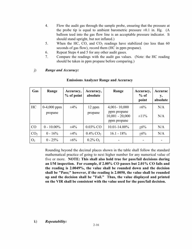
j) Range and Accuracy:
Emissions Analyzer Range and Accuracy
Gas
Range
Accuracy, % of point
Accuracy, absolute
Range
Accuracy,
% of point
Accurac
y, absolute
HC
0-4,000 ppm
propane
±4%
12 ppm propane
4,001- 10,000 ppm propane
10,001 - 20,000 ppm propane
±6%
±11%
N/A
N/A
CO
0 - 10.00%
±4%
0.03% CO
10.01-14.00%
±6%
N/A
CO2
0 - 16%
±4%
0.4% CO2
16.1 - 18%
±6%
N/A
O2
0 - 25%
±6%
0.2% O2
-
-
-
Rounding beyond the decimal places shown in the table shall follow the standard mathematical practice of going to next higher number for any numerical value of five or more. NOTE: This shall also hold true for pass/fail decisions during an I/M inspection. For example, if 2.00% CO passes but 2.01% CO fails and the reading is 2.0049%, the value shall be rounded down and the decision shall be "Pass;" however, if the reading is 2.0050, the value shall be rounded up and the decision shall be "Fail." Thus, the value displayed and printed on the VIR shall be consistent with the value used for the pass/fail decision.
k) Repeatability:

2-17
Emissions Analyzer Repeatability
Gas
Range
Repeatabilit
y, % of point
Repeatability, absolute
Range
Repeatabilit
y, % of point
Repeatability, absolute
HC
0-1400 ppmh
±2%
3 ppmh
1400-2000
ppmh
±3%
N/A
CO
0 - 7.00%
±2%
0.02% CO
7.01-10.00%
±3%
N/A
CO2
0 – 10%
±2%
0.1% CO2
10 - 16%
±3%
N/A
O2
0 – 25%
±3%
0.1% O2
-
-
-
Accuracy and repeatability shall be defined by the test procedures in Section 5.
l) Noise:
Emissions Analyzer Noise
Gas
Range
Noise, % of
point
Noise,
absolute
Range
Noise, % of
point
Noise,
absolute HC
0-1400 ppmh
±0.8%
2 ppmh
1400-2000
ppmh
±1%
N/A
CO
0 - 7.00%
±0.8%
0.01% CO
7.01-10.00%
±1%
N/A
CO2
0 – 10%
±0.8%
0.1% CO2
10 - 16%
±1%
N/A
O2
0 – 25%
±1.5%
0.1% O2
-
-
-
Noise shall be defined operationally as follows: Sample Mid Range #1 Audit Gas for 20 seconds. Collect all the analyzer output readings for each channel over the 20 seconds. (For example, if the analyzer outputs are read by the EIS at the rate of twice per second, the total number of readings would be 40.)
2-18
m) Minimum Analyzer Display Resolution: The analyzer electronics shall have sufficient resolution and accuracy to achieve the following:
HC 1 ppm HC CO 0.01% CO CO2 0.1% CO2 O2 (optional) 0.1% O2 RPM 1 RPM
n) Display Refresh Rate: Dynamic information being displayed shall be refreshed at a minimum of twice per second. Alternatives may be submitted to the County for its approval.
o) Interference Effects: The interference effects from non-interest gases shall not
exceed ±4 ppm for HC, ±0.02% for CO, ±0.20% for CO2. Corrections for collision-broadening effects of combined high CO and CO2 concentrations shall be taken into account in developing the factory calibration curves, and is included in the accuracy specifications. Interference gases shall be as follows:
Interference Gases
16% Carbon Dioxide in Nitrogen 1600 ppm Hexane in Nitrogen 10% Carbon Monoxide in Nitrogen 75 ppm Hydrogen Sulfide in Nitrogen 75 ppm Sulfur Dioxide in Nitrogen 18% Carbon Dioxide and 9% Carbon Monoxide in
Nitrogen Water-Saturated Hot Air
NOTE: Interference gases shall have a ±2% blend tolerance and ±2% certified accuracy.
p) Warm-up Time: The analyzer shall reach stability within 30 minutes at 35oF
from startup. If an analyzer does not achieve stability within the allotted time frame, it shall be locked out from I/M testing and a message shall be displayed instructing the operator to call for service.
q) System Lockout During Warm-up: Functional operation of the gas sampling unit
shall remain disabled through a system lockout until the instrument meets stability and warm-up requirements. The instrument shall be considered "warmed-up" when internal analyzer verifications are complete and the zero readings for HC, CO, CO2, and O2 have stabilized, within the allowable accuracy values, for five minutes without adjustment.
2-19
r) Analyzer/Sensor Response Times Analyzer/sensor response times are defined as follows:
1. Rise time: When a gas is introduced to a sensor’s sample cell inlet or inlet
port (t0), the time required by the sensor’s output to rise from first indication of response to the input gas to a given percentage of the final stable reading of a gas’s concentration. Two rise times are specified:
i. T90: The time required to reach 90% of the final gas
concentration reading from first indication of response to the input gas.
ii. T95: The time required to reach 95% of the final gas
concentration reading from first indication of response to the input gas.
2. Fall Time: When a gas is removed from a sensor’s sample cell inlet or
inlet port (tS), the time required by the sensor’s output to fall from first indication of withdrawal of the gas to a given percentage of the final stable reading of a gas’s concentration. Two fall times are specified:
i. T10: The time required to fall to 10% of the stable gas
concentration reading from first indication of withdrawal of the gas.
ii. T5: The time required to fall to 5% of the stable gas
concentration reading from first indication of withdrawal of the gas.
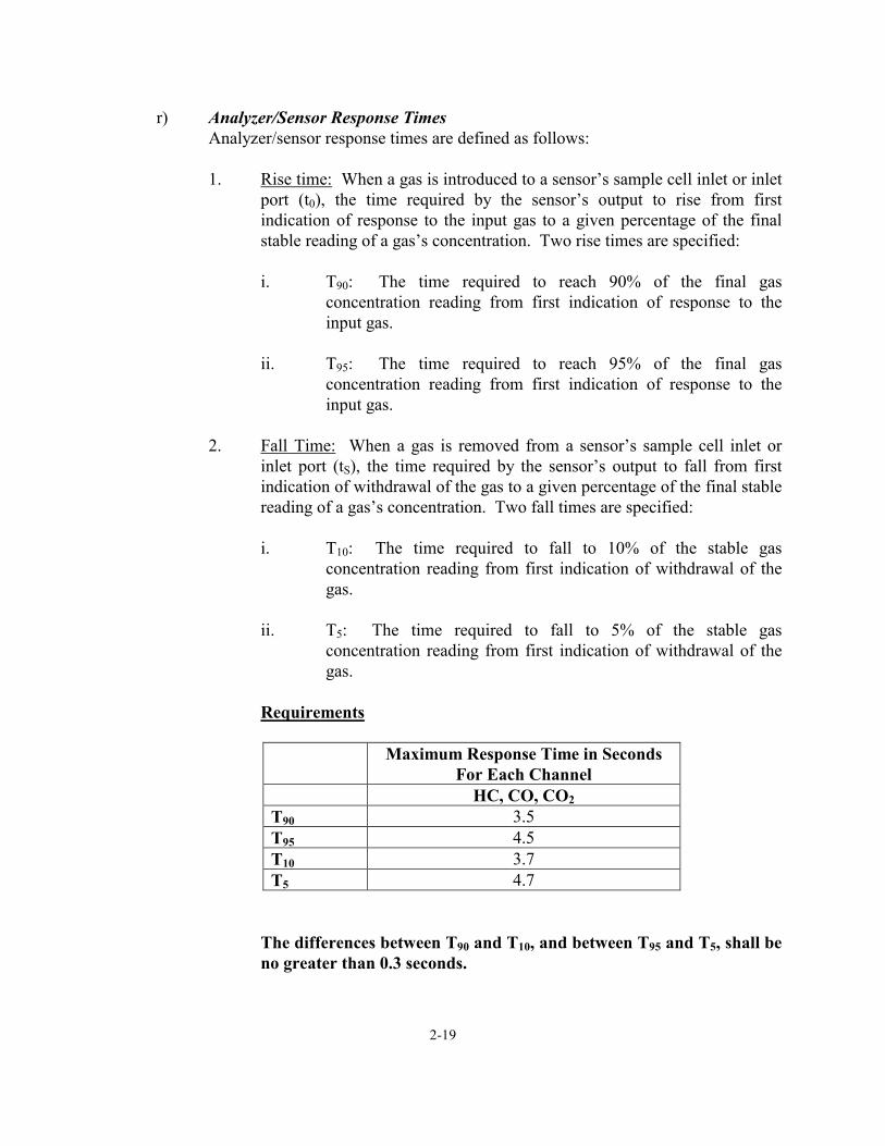
Requirements
Maximum Response Time in Seconds
For Each Channel HC, CO, CO2 T90 3.5 T95 4.5 T10 3.7 T5 4.7
The differences between T90 and T10, and between T95 and T5, shall be no greater than 0.3 seconds.

2-20
Note that the oxygen (O2) sensor's response time is specified as an overall system response time (see Section 2.4.6,g) in harmony with the generally-accepted European specifications.
s) HC Hang-up
When the analyzer performs a HC hang-up check before the start of an emissions inspection, the recorded ambient air readings shall be subtracted from the sampled readings to determine the amount of HC hang-up (residual HC) in the sampling system.
The analyzer shall be locked out from official emissions testing until (a) the ambient air has less than 15 ppm HC and 0.02% CO , and (b) until the residual HC obtained through the sample probe is less than 20 ppm propane.
t) Emissions Accounting/Accuracy
The manufacturer shall ensure that its analytical system provides an accurate accounting of the actual exhaust emissions produced during the test, taking into consideration the individual channel accuracy’s, repeatability’s, interference effects, sample transport times and analyzer response times.
2.4.6 Sampling System Components
a) General: The system shall be designed to ensure durable, leak-free operation and be easily maintained.
The sampling system shall be designed to withstand typical vehicle exhaust temperatures and high throughput, as when the vehicle is driven through a TSI test cycle for 120 seconds.
Materials that are in contact with the gases sampled shall not contaminate or change the character of the gases to be analyzed. The sampling system shall be designed to be corrosion-resistant for at least five years.
b) Sample Hose: The sample hose shall be 25 ft ±0.5 ft in length, when measured
from the front of the EIS cabinet. Other configurations may be submitted to the County for its consideration
The hose material in contact with the exhaust sample shall be nonporous, and shall not absorb, adsorb, react with, or affect the sample in any manner. The outer coating of the hose shall be abrasion-resistant and unaffected by the substances found in a typical service facility’s environment.
The sample hose shall be flexible, yet shall resist kinking and crushing, as defined in Section 5.

2-21
The sample hose shall be connected to the probe and to the analyzer sample system with screw-type fittings.
c) Sample Hose and Probe: The sample hose and probe shall withstand exhaust gas
temperatures at the probe tip of up to 1100oF for five (5) minutes.
d) Sample Probe: The analyzer manufacturer shall equip the analyzer with a sampling probe which meets the following criteria:
1. Retention - The probe shall incorporate a positive means of retention to
prevent it from slipping out of the tailpipe when in use.
2. Hand Grip - A thermally-insulated, securely-attached hand grip shall be provided on the probe in such a manner that easy probe insertion using one hand is insured.
3. Flexibility - Manufacturers shall supply two types of removable probe tips
with each analyzer sold. The probe and both probe tips shall meet the following criteria:
i. the probe shall be designed so that the tip extends 16 inches into
the tailpipe; ii. the probe and probe tip should be designed so the average garage
operator can easily remove and reinstall them without special tools;
iii. a handle, made of thermally insulating materials, shall be attached to a rigid, reasonably non-crushable portion of tubing made of stainless steel or something equivalent, which can be easily removed from the sample line and reinstalled by the operator; and
iv. the probe tip shall be shielded so that debris is not scooped up by the probe when it is inserted into the tailpipe.
v. In addition, one of the probe tips supplied with the analyzer shall be of the traditional style meeting the following specifications:
a. flexible enough to extend into a 1½-inch diameter exhaust
pipe having a three-inch radius, 45-degree bend; and b. the flexible portion shall be constructed so that it is sealed
to prevent any sample dilution.
vi. Manufacturers shall also supply the analyzer with an essentially straight probe tip (no more than a 15o bend) meeting the following specifications:

2-22
a. made of either stainless steel, 3/16 inch outside diameter (O.D.) solid-wall tubing, which is readily available; and
b. designed so that the connector between the removable probe tip and the rigid portion of tubing is up inside the tailpipe at least three inches to reduce the effects of any leak that might occur.
4. Serviceability - For the purposes of economical replacement, the flexible
portion of the probe assembly shall be designed so it can be replaced. The probes supplied shall be readily available.
5. Materials - The probe shall be made of materials that will withstand
exhaust temperatures up to 1100oF. Use of dissimilar metals with thermal expansion factors of more than five percent shall not be used in either the construction of probes or connectors.
6. Audit Gas Introduction - Probes shall be designed to allow, or shall be
supplied with an adapter allowing, the introduction of audit gas from a one-half inch inside diameter flexible hose. The probe tip or the adapter shall be sized to provide a tight fit so that dilution cannot occur at the probe/hose connection.
7. Probe Cap - A probe tip cap suitable for performing a system leak check
shall be provided if the vacuum decay method of leak check is utilized. Otherwise, whatever hoses and connectors are necessary shall be provided to allow the operator to perform the leak check.
e) Particulate Filter, Water Trap and Sample Chiller
1. The particulate filter shall be capable of trapping 97% of all particulates
and aerosols 5 microns or larger.
2. The filter element shall not absorb or adsorb hydrocarbons.
3. The water trap shall be sized to remove exhaust sample water from vehicles fueled with gasoline, gasohol, propane, compressed natural gas (CNG), as well as with alternative and oxygenated fuels, such as methanol (M85), ethanol (E85), and reformulated gasolines with MTBE as the oxygenate. The filter element, bowl and housing shall be inert to these fuels as well as to the exhaust gases from vehicles burning these fuels. The condensed water shall be continuously drained from the water trap's bowl. Sufficient water shall be trapped, regardless of fuel, to prevent condensation in the sample system or in the optical bench's sample cell.

2-23
4. The sample system shall incorporate a chiller to enhance water separation and system performance and extend analyzer life.
f) System Leak Check: The analyzer shall require that a leak check be successfully
passed every 24 hours.
During a leak check the analyzer shall not allow an error of more than +1% of the High Range calibration gas reading (UTAH 2000 span gas). A leak equivalent to a reading error greater than +1% shall be cause for failing the leak check.
g) System Response Time Requirements For Analyzer Channels: The overall system response time of the analytical train comprises the Transport Time and the Analyzer/Sensor Response Time (see Section 2.4.5 r).
1. Transport Time: The time from the exhaust sample's entry into the tip of
the sample probe until the analyzer/sensor first begins to respond to the sample. The Transport Time shall be no more than 5 seconds for HC, CO and CO2 and no more than 7.5 seconds for O2.
2. System Response Time:
i. HC, CO, & CO2 Channels: The response rise time (see §2.4.5.r)1) from the probe to the display shall be no more than eight (8) seconds to T90. In addition, the response fall time shall be no greater than 8.3 seconds to T10.
ii. O2 Channel: The response rise time shall be no greater than
15 seconds to T90. The response fall time for a step change in concentration from 20.9% O2 to 0.1% O2 shall be not greater than 40 seconds.
h) Hang-up Check [Ref. Section 2.4.5 s)]
Activation of the emission measurements mode of the EIS shall be prevented unless a successful hang-up check has been performed immediately prior to the test sequence. The sample system's Hang-up shall not exceed 20 ppm propane prior to testing. A unit with a clean sample system shall have an HC hang-up time of no more than 120 seconds. If the HC hang-up does not drop below 20 ppm propane within 150 seconds, the following message shall be displayed: "POSSIBLE DIRTY FILTERS OR SAMPLE LINE."
i) Dilution
The analyzer supplier shall demonstrate to the satisfaction of the County that the flow rate on the EIS unit shall not cause more than 2% dilution during sampling of the exhaust of a 1.6L engine at normal idle. Two percent dilution is defined as a sample of 98% exhaust and 2% ambient air.

2-24
j) Back-Purge The sample system must automatically back purge the sample system after and in between each test. A minimum pressure should be used for this purpose. The high pressure pack-purge serves to extend the life of the analyzer by flushing out particulates, moisture and HC's remaining in the sample line after each test
2.4.7 Temperature Operating Range
The analyzer, including all of the software/hardware enclosed in the cabinet, shall operate within the performance specifications described herein in ambient air temperatures ranging from 35o to 110oF. Analyzers shall be designed so that adequate air flow is provided around critical components to prevent overheating (and automatic shutdown) and to prevent the condensation of water vapor which could reduce the reliability and durability of the analyzer.
2.4.8 Humidity Operating Range
The analyzer, including all of the software/hardware enclosed in the cabinet, shall operate within the performance specifications described herein at up to 85% relative humidity throughout the required temperature range.
2.4.9 Opacity
An opacity option shall be offered for use in testing light- and medium-duty diesel-powered vehicles. It shall be a partial-flow device, meeting the performance requirements of ISO 11614, and shall interface seamlessly with the analyzer software via an RS232C port. A DB25 pin serial port or other County- approved connector is required. Adjustments such as electronic signal filtering shall be incorporated so as to correlate with other opacity-measuring devices and standards. Other methods of measuring opacity may be submitted for County consideration. The devices shall be calibrated by a method and at a frequency approved by the County.
2.4.10 Ambient Temperature Measurement
Ambient temperature shall be measured prior to the start of every inspection, and shall be recorded in the Ambient Temperature field of the test record. The temperature measuring device shall have the following minimum characteristics:
Range: 0 - 140oF Accuracy: ±3oF
2.5 CABINET & PERIPHERAL REQUIREMENTS
All cabinets, including modifications are subject to County approval and shall be tamper resistant as specified in §1.4.
2.5.1 Power/Telephone Cord

25
The modem shall be designed to connect to the EIS by means of a modular telephone connector with a standard wiring configuration. The connector shall be located on the back of the analyzer cabinet. Alternatives to this requirement to improve the durability of the connection interface and the telephone line are encouraged and may be proposed by the manufacturer for evaluation by the County. The telephone cord shall not be attached to the power cord. The telephone line shall be enclosed in a protective cable meeting County and UL approval. Alternative methods to protect the telephone line may be submitted to the County for approval.
The manufacturer shall include provisions to ensure that the power necessary to activate the modem at the appropriate time is available.
The analyzer shall be supplied with a 25-foot UL-approved power cord. The manufacturer shall design the cabinet so that convenient storage is provided for the excess cord not needed to reach the nearest power outlet.
2.5.2 Power Requirements
The EIS shall operate only on alternating current (AC). No direct current (DC) models will be acceptable. The EIS shall not be powered by a portable AC generating unit. An exception to this rule may be sought by the manufacturer if it can be shown, to the satisfaction of the County, that the analyzer is immune to the line frequency variations of the portable AC generating unit. Immunity to line frequency variations is defined here as line frequency variations which will not cause more than one percent of full scale (FS) disturbances on any of the analyzers. Additionally, any AC portable generating unit used with the EIS shall not have frequency excursions exceeding one hertz from 60 hertz.
Input power shall be 115 VAC, 60 hertz. All instruments shall meet the specified requirements over an input voltage variation of at least ±12 volts. Maximum allowable performance change due to line voltage variations shall not exceed one-third of the accuracy requirements.
2.5.3 Instrument Construction
The instrument shall be designed and constructed to provide reliable and accurate service in the automotive repair environment. The analyzer shall be supplied with a cabinet which is equipped with a storage area large enough to secure all accessories and operating manuals.
a) Materials
The materials used in instrument construction shall be resistant to corrosive type substances found in the automotive repair environment and be designed to last for at least the period of the warranty.
b) Finish
The exterior and interior finish of the entire cabinet and console shall be sufficiently durable to withstand the chemicals and environmental conditions
26
normally encountered in the automotive repair environment for the period of the warranty.
c) Mobility The analyzer may be permanently mounted or mobile with wheels. Wheels shall be at least five inches in diameter and have a locking mechanism capable of preventing movement on a 15o incline.
If mobile, the analyzer shall be designed so that movement over rough surfaces (three-inch deep holes) and on 15o inclines, will not cause it to tip over. Analyzers shall not tip over when placed at the center of an inclined plane that makes an angle of 10 degrees with the horizontal and rotated 360o stopping in the position where it is most likely to tip over. In addition, the analyzer shall not become unstable or tip over when rolled straight off the edge of a two-inch high platform or when one wheel is rolled over a drain, two inches below the surface, inside an 18-inch diameter depression.
d) Identification
The analyzer serial number and the date of production shall be conveniently displayed to the quality assurance inspectors and the County field representatives, in a manner meeting the County's approval. The first two characters of the EIS number shall be alphas denoting the manufacturer's initials, and shall not be changeable from the keyboard even in the manufacturer's service mode. The initials chosen are subject to approval by the County to prevent duplication between manufacturers. The remaining six characters shall be numeric. The numbers shall be right justified. Zeroes shall be used to fill any blank spaces between the initials and the numerics. For example, the EIS number for analyzer #23 from Hobo Electronics would be "HE000023."
e) Electrical Design
Provisions shall be made for storing the power cord in a manner satisfactory to the County. Fuses or circuit breakers shall be used to protect individual electrical circuits and emission analyzers. Main circuit breakers and fuses shall be readily accessible from the exterior of the cabinet. Analyzer operation shall be unaffected by electrical line noise and voltage surges. The analyzer shall be sufficiently protected from voltage surges to prevent damage to the analyzer from the simultaneous start up of a 220-volt compressor, an arc welder, hydraulic controls and other equipment commonly found in the typical automotive test and/or repair environment.
f) Electromagnetic Isolation and Interference
Electromagnetic signals found in an automotive environment shall not cause malfunctions or changes in accuracy in the electronics of the EIS. The instrument design shall insure that readings do not vary as a result of electromagnetic radiation and induction devices normally found in the automotive garage
27
environment (including high energy vehicle ignition systems, RF transmission radiation sources and building electrical systems).
In addition, the manufacturer shall ensure that the analyzer processor and memory components are sufficiently protected to prevent the loss of programs and test records.
g) Vibration and Shock Protection
System operation shall be unaffected by the vibration and shock encountered under the normal operating conditions encountered in an automotive environment. Instruments, motors, pumps, and disk drives shall be shock-mounted to absorb any vibration which might affect the system operation.
h) Instruction Manual & Accessories Storage
A storage area shall be provided to store the analyzer operating instruction manual and UTAH 2000 accessories.
2.6 BAR CODE SCANNER**
A non-contact two dimensional bar code scanner capable of reading both 1-D and 2-D bar codes, including code 39, PDF-417, UPC labels and 128 symbologies and all necessary interface software and hardware designed to read labels meeting SAE specifications J1877 and J1892 is required on all analyzers**. The bar code scanner shall be able to auto-discriminate between the symbologies. The bar code scanner shall be capable of reading a VIN through a windshield. The bar code scanner shall be capable of reading a DMV bar code having a maximum length of 7¼" (seven and one quarter inches).
In addition to collecting information from the VIN label, scanners may also be required to enter emission application information from the County recognized abbreviated lookup manuals.
The County recommends that the manufacturers contact the vehicle manufacturers to inquire about obtaining bar-coded labels for testing purposes.
2.6.1 Minimum Required Configuration for Bar Code Scanner The analyzer shall be equipped with a standard port configuration and standard connector (such as DB9 or DB25 RS232C external connector) for the bar code scanner. Scanner and communication must be County approved (proprietary scanner systems will not be permitted). The bar code scanner will be used to load emission control system information from application manuals and from the permanent bar code labels placed on the vehicle by the manufacturer. The supplied bar code scanner shall come with at least a twenty (20) foot long self coiling cord and be able to read bar codes placed on the door frames and under the hoods. Manufacturers will be expected to include any software necessary to utilize the data gathered from labels.
**The bar code scanner shall be standard, "off-the-shelf" technology approved by the County.

28
2.7 FUEL CAP TESTER The UTAH 2000 EIS shall include a fuel cap testing system meeting the following specifications. The fuel cap tester must be provided as an integrated component located internally within a secured area of the EIS cabinet. All electronic components, flow sensors, controlling switches, and solenoids, with the exception of the hose and gas cap adapters, must be mounted within the secured area of the EIS cabinet. Fuel Cap Testers must be certified by the California Bureau of Automotive Repair or equivalent laboratories approved by the County.
a) The fuel cap tester shall test the leak rate of fuel caps to prevent evaporative
emissions.
b) The tester shall be designed so that tethered caps can be accommodated without moving the EIS and shall be capable of pressurizing the fuel cap for this test. The pressurizing system shall apply a controlled pressure of 30 in. H2O to the fuel cap. The system shall indicate a fail if the leak rate is greater than 60cc per minute. The system shall indicate a pass if the leak down rate is 60cc or less per minute. The leak test shall last no longer than 120 seconds.
c) The tester shall have the capability to change the leak rate pass/fail setpoint if
needed at a later date.
d) The system shall be tamper resistant.
e) Fuel cap test equipment shall indicate a pass/fail condition.
f) The tester shall have an indicator and/or screen prompt informing the technician when the system is ready to test (pressurized ).
g) The tester shall have a means of controlling the maximum reservoir pressure and
relieving overpressure.
1. The fuel cap tester shall communicate with the UTAH 2000 EIS to record information such as pass/fail, calibration, etc. Communication and power to the unit shall be internal to the EIS cabinet.
j) Calibration and Accuracy
1. Each system will have a calibrated screened orifice for calibration
PASS/FAIL determination. The set shall be individually calibrated; the calibration shall be traceable to the NIST. The master calibration set shall consist of a PASS MASTER flowing 52 to 56cc per minute and a FAIL MASTER flowing 64 to 68cc per minute (both measured at 30 in. H2O pressure). The tester shall be calibrated every three days with the master calibration set. The calibration set shall be calibrated before initial usage.
29
The calibration method shall be NIST traceable. Equipment out of calibration may not be used.
2. The tester accuracy shall be ±3cc per minute and shall be capable of
maintaining its accuracy from 35o to 110oF and at elevations from -60 to 7,000 feet.
k) Adapters
1. The system shall be capable of testing at least 95% of the County motor
vehicle fleet (excluding pressurized fuel systems such as CNG, LPG, etc.) that are equipped with evaporative control systems.
2. As soon as adapters are available for new designs they should be made
available for sale to the EIS owners within a period of one year of their introduction.
3. Adapter sets shall have a means of indicating or cross-referencing which
vehicles they fit. 2.8 ENGINE RPM DETECTION
The analyzer shall utilize a tachometer capable of detecting engine RPM with a 0.5 second response time and an accuracy of ±3% of the true RPM. Prompts may be provided to assist the technician in locating an RPM signal on vehicles equipped with DIS. Based on the vehicle identification information entered by the technician, the analyzer shall advise the technician regarding which vehicles require a primary pick up, which require that an alternate counting algorithm be used and which require the use of an auxiliary piece of equipment. Analyzers shall be provided with all the software and hardware that is necessary to make them capable of reading engine speed on all vehicles manufactured prior to analyzer certification that are included in the Inspection Program (except those powered by diesel engines). As a minimum, analyzers must be equipped with a spark plug wire direct pickup, a non-contact pickup, and an OBD II interface connection. For analyzer certification, analyzers shall be capable of reading engine RPM on all spark ignition vehicles. Beginning with 1996 model year vehicles, the system shall be capable of detecting engine RPM via OBD II.
2.9 ACCESSING OBD II FAULT CODES
Analyzer manufacturers must incorporate provisions for reading fault codes from vehicles with on-board diagnostics II (OBD II) using the Standardized Link as defined by SAE J1979 and J1978. The SAE Standardized Link shall connect to the vehicle's on-board diagnostics port to automatically interrogate and retrieve fault codes. The OBD II hardware must adhere to the communications protocols and hardware requirements as defined by SAE J1979 and J1978 specifications. The OBD II hardware must be maintained in the secured area of the EIS cabinet with the exception of the cable to the vehicle. Hardware and software shall be seamless to the user.
30
2.10 TESTING HEAVY-DUTY GASOLINE-POWERED VEHICLES Manufacturers shall supply the analyzer with the hardware and software necessary to test heavy-duty gasoline-powered vehicles manufactured prior to certification. At a minimum, accessories shall allow for 40-foot motorhomes to be tested without degrading the emission analyzer response time and provide the technician with an accurate indication of the engine speed.
2.11 DUAL EXHAUST For vehicles with dual exhaust, the analyzer supplier shall provide a dual probe-and-hose arrangement, designed so that the flows from each tailpipe reach the main sample hose at the same time and shall have the same flow ±10%. A quick-connect coupling may be used to connect an auxiliary probe and hose, but no quick-connect coupling shall be used in the primary single-exhaust path. The quick-connect fitting, if used, shall have a leak-proof shutoff when not in use.

3-1
SECTION 3. UTAH 2000 SOFTWARE SPECIFICATION 3.1 OVERVIEW
Section 3 specifies the software requirements for UTAH 2000 emission inspection systems (EIS). It includes inspection procedures, sequences, decisions, responses and prompts, as well as necessary information, security issues, lockouts, file structures, etc. It also contains requirements for communication with the County’s Vehicle Information Database (HOST). Important note: In general, when the wording of a prompt is not specified (or is paraphrased) it is up to the manufacturer to coordinate with the County to reach an agreement as to the specific wording to be used. This specification is designed to set the groundwork or foundation for the operation of the software for its functions, and at times is specific as to tasks, wording, processes and functions. It has been designed with flexibility in mind to allow for reaching the solution to each task using a method or methods deemed easier or more efficient by the manufacturer as long as the functionality is in place and the method(s) used do not undermine the intent of this specification.
3.2 UTAH 2000 SOFTWARE COMPONENTS 3.2.1 General
The program software used in the EIS shall consist of a process control system as well as data look-up files necessary to conduct official vehicle inspections that meet the UTAH 2000 specifications. The software shall consist of inspection test procedures and criteria; necessary station, technician, and vehicle information; security measures, utilities and ancillary software modules. The software's features shall include vehicular emission measurements of HC, CO, CO2, and O2, engine RPM measurements, exhaust dilution determinations, bar code scanning, interface with OBD II, communication with the HOST, safety testing, gas cap testing, etc. The Manufacturer may offer additional features, which are not required by this specification, so long as these items do not defeat or interfere with the integrity or purpose of this specification.
3.2.2 Boot-up Configuration
On each power-up, the EIS shall automatically self-diagnose all computer systems, including memory, hard disk and loading of all necessary operating software without technician intervention. If any corruption is found on the hard disk during the boot sequence and if check files are created (usually saved as *.chk files), then the check files must be deleted so that the hard disk will not contain an excessive number of these files. Upon satisfactory computer component checkout (including hard disk and data structures), the application software shall present the Main Menu of the available EIS operations. All offered features shall be menu-driven. For inspection related features,

3-2
context-sensitive, on-line help shall be provided which can be accessed preferably with a single keystroke.
3.2.3 Software Modifications and Software Update Certification
Periodic software updates will be necessary. The County or the manufacturer may require software updates. In either case, the manufacturer is responsible for installing the software in all EIS units. The first four updates must be included as part of the EIS initial cost. The cost of subsequent software updates is the responsibility of the EIS owner if the software update is required by the County but is the responsibility of the manufacturer if they require the update to fix a problem that went undiscovered until after its release. These revisions are likely to occur within the first two years of the enhanced vehicle inspection program and their costs shall be included in the quoted initial purchase price for the base system. Updates to the software specifications will be provided to the manufacturer by the County. The manufacturer shall provide the software program to the County upon each update. The software version number is to be indicated on the EIS status screen, Main Menu, on each vehicle test record and the VIR. The version number shall consist of a four digit numeric code to be made up of the following format X.XX. Where the first version submitted will be 1.00 and each update will require the number to be incremented by a value of "0.01". For example, the 10th submittal will read 1.10.
All software updates shall cause the software version number to change. There will be a separate field in the test record indicating the software version currently in use
Areas in the software where changes or additions might be required include (but are not limited to):
• Preconditioning procedures and emission test sequences (as applicable for two-speed idle tests);
• Various lookup/reference tables; • Functional tests; • Diagnostic and repair procedures; • Data communication procedures; • Criteria affecting emission standards selection, vehicle exemptions and
vehicle pass/fail criteria. Other areas not specifically mentioned might also be impacted at some point, but we do not expect to request changes in all these areas at once.
To maintain the integrity of the County's I/M program, County field personnel will be instructed to lock out The UTAH 2000 units that have unauthorized modifications or are running unapproved software versions. The following criteria apply to software and software updates:

3-3
a) Only the County-approved software shall be used in the UTAH 2000 units conducting official inspections. The County intends to accommodate software developed by third parties as long as system security and integrity are not compromised. In addition, the County may initiate the development of software updates by third parties for use in all UTAH 2000 units. If the County initiates development of a software update, manufacturers shall cooperate with the County and/or the County-approved third party.(This section does not prohibit manufacturers from charging reasonable fees for software updates or from requiring nondisclosure agreements when software updates are developed by third-parties.)
b) All proposed software updates must be thoroughly tested by the manufacturer
before being submitted to the County. Update disks as well as electronically transmitted updates shall be encrypted in a manner approved by the County. The EIS shall be capable of accepting software updates via CD.
c) All proposed software updates generated by the manufacturer shall be submitted
to the County with a written description list of the reason(s) for the update, such as the problem(s) that the update corrects.
d) All proposed software updates, including manufacturer-generated updates, must
be submitted to the County for testing and approval as follows:
1. Software updates must be submitted on a mutually agreed upon medium. 2. Each new software version submitted to the County, including minor
revisions, must have a new and unique software version number. 3. All proposed software updates must be accompanied by a cover letter with
the following information: i. A description of all of the changes contained in the proposed
software update, including manufacturer-initiated modifications. ii. A timeline of when the update is expected to be installed (start to
finish) and how many units will be updated. iii. If any hardware modifications or special procedures are needed to
perform the software update, describe the procedures for performing the update.
4. Depending on the type and number of changes contained in the proposed software update, the County may require testing at the County-approved beta sites prior to release of the software. The County will perform a preliminary review of the proposed software prior to releasing it for either full use or beta site testing.
e) The manufacturer is allowed six months, from the date the County issues its
finalized specifications, for periodic software updates to submit for approval and testing by the County. Prior to the six-month period, the manufacturer shall be permitted to review and to comment upon the proposed specifications. If,

3-4
however, a previously installed update does not meet the specifications, the County may require a shorter time period. Failure of a manufacturer to furnish or install software updates as specified, is cause for the County to decertify the manufacturer's EIS Certification, or to issue a citation and civil penalty up to $1,000 per week that the manufacturer fails to furnish or install the software updates. (The County may allow additional time to review and comment and/or submit software updates if the modifications are more complex.)
3.2.4 Running Changes and Other Software Modifications
Any changes to design characteristics, component specifications, and any modifications to the software must be approved by the County. It will be the manufacturer's responsibility to confirm that such changes have no detrimental effect on the performance of the UTAH 2000.
3.2.5 Virus Detection Software
Each EIS unit shall contain a virus detection program, subject to the County approval, which shall verify the integrity (i.e. check for infection/corruption) of each update disk or decompressed file before it is applied to the EIS or allowed in memory. Infected/corrupted software shall be blocked from installation.
In lieu of this requirement, the EIS manufacturer may submit for the County's consideration written procedures clearly illustrating how the EIS manufacturer intends to meet the intent of the VIRUS PROTECTION PROGRAM requirement. These procedures shall demonstrate how the integrity of the EIS software and update software or decompressed file shall be protected under all circumstances.
3.2.6 Directory, File Structure and File Storage
When data is being stored or accessed, the computer shall display a message indicating that the disk is in operation and the EIS shall not be moved or disturbed. All information relating to vehicle emissions and OBD II inspections, calibrations, repairs, and safety inspections shall be stored onto the hard drive. Any information that must be sent to the HOST must also be stored onto the 3.5 inch floppy drive. The frequency of storage during testing shall be, at the very least, once per test immediately at the end of the inspection but before the printing of the inspection report. More frequent saves to the drives are permitted and encouraged. The EIS shall keep in storage on the hard drive, at the very least, the last one thousand (1,000) vehicle inspections, the last one thousand (1,000) safety inspections, the last one thousand (1,000) repair records and the last one hundred (100) calibration records. All station related information and all information that remains unsent to the HOST shall be stored onto the 3.5 inch floppy drive (usually the A:Drive) as well as onto the hard drive. This shall allow the analyzer to recover any information that has not been sent to the HOST and station information in the event of a hard drive failure.
3.2.7 Display

3-5
a) Readability The display, when in the test mode, shall be readable at a minimum distance of eight feet in a building that meets OSHA lighting standards for a garage environment. Display contrast and brightness shall be adjustable.
b) The County Messages (Technical Service Bulletins (TSB))
The County messages shall be transmitted by the HOST to the EIS during all communication sessions. All new messages shall be displayed immediately after the HOST contact. The EIS shall display these messages one-time-only and shall provide an option to print and an option to save. All displayed messages shall default to print and the technician must press a function key to continue. All messages from the HOST shall be deleted after the first viewing, unless specified otherwise by the technician.
c) Testing Messages
During the emissions test, the EIS shall display the word TESTING on the screen. The EIS shall also display messages such as test mode, vehicle engine speed, excessive exhaust dilution, low flow and engine RPM violations.
d) Information Not Permitted During Testing
The EIS shall not display the emission readings during the inspection. (However, during manual mode, the readings shall be displayed.)
e) Print Screen Capability
The EIS shall have a PRINT feature, which prints any current text or graph displayed on the screen, by depressing no more than three keys. The print feature shall always be active; however, there shall be no print capability during emissions testing.
3.2.8 Technician and Station License Numbers and Other Numbers
a) General: The technician's license number and access code shall reside in both the EIS and
the HOST. The EIS shall determine the validity of the technician's access code with the Technician Information Records.
The EIS shall have the capacity to store at least 99 technician access codes and 99
corresponding Technician License numbers. Only through the County Menu and the HOST can the technician's access code and corresponding license number be added, changed or deleted. Station and technician license numbers begin with three (3) alpha characters, followed by six numeric characters.
b) Technician Access Codes:
The EIS shall require the technician to enter a special access code before an inspection can begin. The access code shall neither be displayed nor printed on
3-6
the VIR. This special access code number shall be linked to the technician's license number.
c) Technician License Numbers:
A technician's license number reflects the type of license the technician possesses. The EIS shall automatically abort the inspection and display a message indicating that the technician has not obtained the proper license number and/or endorsement from the County.
d) Station License Number:
The station license number shall be entered into the EIS during initialization. Only valid station license numbers may be entered into the EIS. The station license numbers are unique to each station. The station license number shall be placed in the Station Number I/M field of the test record and on the VIR. This is field #2 and this field must be populated in the test record for every valid test record sent to the HOST.
e) Test Record Number
The EIS shall give each valid test a consecutive number. A valid test consists of a completed test with an overall pass or fail test result that shall be transmitted to the HOST. The record number shall be written to Test Number field, field #1 of the test record. This field is numeric and has a length of 6 digits. When the number reaches 999999, the number shall be reset to 000001. This field must be populated in the test record for every valid test record sent to the HOST.
f) EIS Number
The EIS number shall be unique for the EIS unit in The County. The first two characters of the EIS number are alpha. These two characters shall be assigned to the manufacturer upon certification of that manufacturer's EIS unit. The following six (6) digits shall be unique to each EIS made by the manufacturer. The EIS number shall be written to the EIS ID field, field #4, of the test record. This field must be populated in the test record for every valid emission test record sent to the HOST. Print the EIS number on the VIR.
g) Loaded Software Version Number
This field shall contain the version number of the software that is currently being used by the EIS. The loaded software version number shall be written to the Software Version field, field #31, of the test record and printed on the VIR. This field must be populated in the test record for every valid test record sent to the HOST.
h) HOST Identification
The HOST-ID is a record identifier generated by the HOST. The HOST shall assign an ID number to a test record which shall be transmitted to the EIS. The ID will be written to the HOST-ID field of the test record. The HOST-ID shall not be

3-7
modified by the EIS and shall be transmitted back to the HOST during transmission of data.
3.2.9 EIS Lockout Reasons
The EIS shall be prohibited from performing an inspection for any of the following reasons:
Warm-up in progress (see Note 1) Warm-up failure (see Note 1) Gas calibration required Gas calibration failure Gas analyzer failure Fuel cap tester failure Fuel cap tester out of calibration Oxygen sensor out of calibration Leak check required Leak check failure EIS tampering Out of certificates Hard disk is full Floppy disk or disk mechanism failure Hard disk or disk mechanism failure County EIS lockout No communication with HOST in XXX days and XXX tests (see Note 2) Failure to pay for test authorization numbers purchased Failure to pay monthly payment County disk drive tampering Technician License Expired Station License Expired
Notes: 1. An analyzer warm-up requirement or failure shall not restrict the UTAH
2000 units from allowing OBD II testing. 2. Example: A lockout shall be set whenever fifty (050) inspections (running
total) have been performed by the EIS within five (005) consecutive days without communicating to the HOST. The HOST sets the no contact limit and number of inspections allowed. The lockout can be cleared by County personnel or by the HOST in accordance with pre-established procedures.
3.3 SOFTWARE MODULES 3.3.1 Utah Main Menu

3-8
Upon boot-up of an EIS unit and after the completion of the boot-up procedures, defined in Section 3.2.1b Boot-up Configuration, the software shall immediately query the analyzer for a warm-up requirement and check the system for any breaches in security that may have occurred while the power was shut off. The software shall display the Main Menu and the results of the warm-up and security checks. Somewhere on the Main Menu the software shall display the software version currently in operation and a clock with the current system date and time. The date and time shall be in the format of MM/DD/YYYY HH:MM AM/PM. In addition, the Main Menu shall display the County logo in which the EIS unit is operating under. The logos will be provided in electronic format at a later date. a) Warm-up:
If the analyzer requires a warm-up, or a warm-up flag is set on the analyzer, the software shall go into a warm-up period whereby analyzer calibrations and official TSI inspections are not permitted. During the warm-up period, the Main Menu shall present a countdown timer displaying the time left in the warm-up period.
b) Security: While in the Main Menu, the software shall periodically, no less than once every second, check for any security breaches. Once a security breach has occurred the software shall display a message on the screen notifying the operator of the violation and shall restrict any official vehicle inspections (safety, TSI and OBD II) and system calibrations. However, other functions shall be allowed after a security breach.
c) Menu Items:
The Main Menu shall display the title "Utah-2000 Main Menu" in larger font relative to that on the buttons and shall be located at the top of the Main Menu screen and centered horizontally on two lines. In addition, the logo of the County in which the individual EIS unit is operating in shall be displayed at the top right corner of the Main Menu screen. Following are a list of options, along with a brief description, that shall be made available from this menu:
Inspection Menu… Gas Analyzer Menu… Shutdown Analyzer Communications Standby
1. Inspection Menu: With the selection of this feature the software shall display the Inspection Menu.
2. Gas Analyzer Menu: With the selection of this feature the software shall display the Gas Analyzer Menu.

3-9
3. Shutdown Analyzer: With the selection of this feature, the software allows the technician to select the Shutdown Analyzer procedure
4. Communications Standby: Selecting this feature allows the technician to place the analyzer in Communications Standby mode, which is required for data transfer. 3.3.2 Inspection Menu
Upon selection of this feature the software shall display the Vehicle Emissions Inspection menu. Somewhere on the Utah 2000 Inspection Menu the software shall display the software version currently in operation and a clock with the current system date and time. The date and time shall be in the format of MM/DD/YYYY HH:MM AM/PM. In addition, the Inspection Menu shall display the County logo in which the EIS unit is operating under. The logos will be provided in electronic format at a later date. a) Warm-up:
If the analyzer requires a warm-up, or a warm-up flag is set on the analyzer, the software shall go into a warm-up period whereby analyzer calibrations and official TSI inspections are not permitted. During the warm-up period, the Vehicle Emissions Inspection menu shall present a countdown timer displaying the time left in the warm-up period.
b) Menu Items:
The Utah 2000 Inspection Menu shall display the title "Utah 2000 Inspection" in larger font relative to that on the buttons and shall be located at the top of the Utah 2000 Inspection Menu screen and centered horizontally. In addition, the logo of the County in which the individual EIS unit is operating in shall be displayed at the top right corner of the Utah 2000 Inspection Menu screen. Following are a list of options, along with a brief description, that shall be made available from this menu:
Emission & Safety Inspection Emission-Only Inspection Safety-Only Inspection Previous Vehicle Information Training Emission & Safety Inspection Analyzer Information Menu… Diagnostic Tools Menu… Communications Diagnostics… Station Manager Menu… Q/A County Menu…
1. Emission & Safety Inspection: Selecting this menu item allows the technician to perform official TSI Emission, OBDII, Gas Cap and Safety Inspections. (See Vehicle Inspection Procedures for details on inspection processes.)

3-10
2. Emission_Only Inspection: Selecting this menu item allows the technician to perform official TSI Emission, OBD II and Gas Cap Inspections.
3. 3. Safety-Only Inspection: Selecting this menu item allows the technician to perform official Safety Inspections.
4. Previous Vehicle Information: Selecting this menu item allows the technician to query Previous Vehicle Information.
5. Training Emission & Safety Inspection: Selecting this menu item allows the technician to access training mode and perform unofficial TSI Emission, OBD II, Gas Cap and Safety Inspections. This feature shall allow technicians to conduct vehicle inspections as described in Section “Vehicle Inspection Procedures” with the following exceptions: (1) Inspections under Training Mode will not be stored and test results will not be transferred to the HOST; (2) The technician shall not be prompted for a password; (3) VIR’s shall not display the certificate shading; (4) VIR’s shall prominently display the words “NOT AN OFFICIAL INSPECTION” across the VIR; and (5) Certificate numbers shall not be issued.
6. Analyzer Information Menu: Selecting this menu item allows the technician to access the Analyzer Information Menu.
7. Diagnostic Tools Menu: Selecting this menu item allows the technician to access the Diagnostic Tools Menu.
8. Communications Diagnostics: Selecting this menu item allows the technician to access the Communications Diagnostics Menu.
9. Station Manager Menu: Selecting this menu item allows the technician to access the Station Manager Menu.
10. QA/County Menu: Selecting this menu item allows the technician to access the QA/County Menu.
3.3.3 Gas Analyzer Menu
Upon selection of this feature the software shall display the Gas Analyzer Menu. Somewhere on the Gas Analyzer Menu the software shall display the software version currently in operation and a clock with the current system date and time. The date and time shall be in the format of MM/DD/YYYY HH:MM AM/PM. a) Warm-up:
If the analyzer requires a warm-up, or a warm-up flag is set on the analyzer, the software shall go into a warm-up period whereby analyzer calibrations and official TSI inspections are not permitted. During the warm-up period, the Gas Analyzer Menu shall present a countdown timer displaying the time left in the warm-up period. The manufacturer recommended warm-up period prior to calibration must be completed. This warm-up period must be submitted to the County for approval.
b) Menu Items:
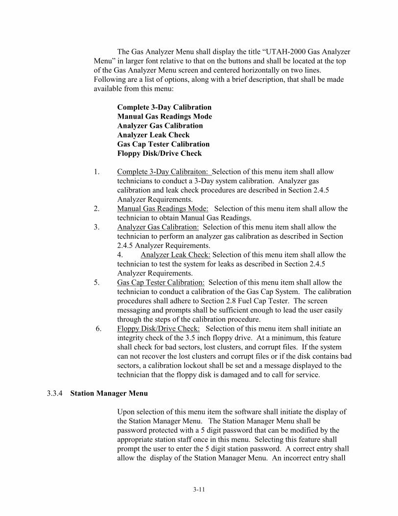
3-11
The Gas Analyzer Menu shall display the title “UTAH-2000 Gas Analyzer Menu” in larger font relative to that on the buttons and shall be located at the top of the Gas Analyzer Menu screen and centered horizontally on two lines. Following are a list of options, along with a brief description, that shall be made available from this menu:
Complete 3-Day Calibration
Manual Gas Readings Mode Analyzer Gas Calibration Analyzer Leak Check Gas Cap Tester Calibration Floppy Disk/Drive Check
1. Complete 3-Day Calibraiton: Selection of this menu item shall allow technicians to conduct a 3-Day system calibration. Analyzer gas calibration and leak check procedures are described in Section 2.4.5 Analyzer Requirements.
2. Manual Gas Readings Mode: Selection of this menu item shall allow the technician to obtain Manual Gas Readings.
3. Analyzer Gas Calibration: Selection of this menu item shall allow the technician to perform an analyzer gas calibration as described in Section 2.4.5 Analyzer Requirements. 4. Analyzer Leak Check: Selection of this menu item shall allow the technician to test the system for leaks as described in Section 2.4.5 Analyzer Requirements.
5. Gas Cap Tester Calibration: Selection of this menu item shall allow the technician to conduct a calibration of the Gas Cap System. The calibration procedures shall adhere to Section 2.8 Fuel Cap Tester. The screen messaging and prompts shall be sufficient enough to lead the user easily through the steps of the calibration procedure.
6. Floppy Disk/Drive Check: Selection of this menu item shall initiate an integrity check of the 3.5 inch floppy drive. At a minimum, this feature shall check for bad sectors, lost clusters, and corrupt files. If the system can not recover the lost clusters and corrupt files or if the disk contains bad sectors, a calibration lockout shall be set and a message displayed to the technician that the floppy disk is damaged and to call for service.
3.3.4 Station Manager Menu
Upon selection of this menu item the software shall initiate the display of the Station Manager Menu. The Station Manager Menu shall be password protected with a 5 digit password that can be modified by the appropriate station staff once in this menu. Selecting this feature shall prompt the user to enter the 5 digit station password. A correct entry shall allow the display of the Station Manager Menu. An incorrect entry shall

3-12
inform the user that the password was incorrect and prompt the user to retry. Three incorrect password entries shall return the user to the Inspection Menu.
a) Menu Items:
The Station Manager Menu shall display the title “UTAH-2000 Station Manager Menu” in larger font relative to that on the buttons and shall be located at the top of the Station Manager Menu screen and centered horizontally on two lines. Following are a list of options, along with a brief description, that shall be made available from this menu:
Review Inventory Load Certificates Menu… Void Certificates Menu… Inventory Warning Settings Station Identification Update Safety Inspector Information Monthly Safety Inspection Report
1. Review Inventory: Selection of this menu item shall display Certificate Inventory.
2. Load Certificates Menu: Selection of this menu item displays the Load Certificates Menu and allows the Station Manager to load emission and safety inspection certificate numbers into inventory. Certificates will have the ability to be entered (loaded) manually, or may be entered by using a Bar Code Scanner. The “Bar Code Scan Certificate” feature shall allow entry of new emissions and safety certificate numbers using the bar code scanner in the event the HOST is not operational. The manufacturer shall develop a method whereby certificates can be embedded into a bar code and then scanned into the analyzer. This method must be secured and restrict unauthorized updates into the analyzer.
3. Void Certificates Menu: Selection of this menu item allows the Station Manager to void emission and safety inspection certificate numbers.
4. Inventory Warning Settings: Selection of this menu item allows the Station Manager to specify when the analyzer should display a warning of low certificate inventory (i.e. Five remaining certificates or 25 remaining certificates).
5. Station Indentification: Selection of this menu item displays station information and allows it to be changed. The only information that shall be allowed to be modified is limited to business name, street number and name, and regular business phone number. The HOST contact number, state, zip code, and station license number shall not be changed through this menu.

3-13
6. Update Safety Inspector Information: Selection of this menu item allows the Station Manager to change the access password to the Station Manager Menu.
7. Monthly Safety Inspection Report: Selection of this menu item shall allow the technician to print monthly safety inspection reports for submittal to the Highway Patrol. Upon entry to this feature, the software shall provide appropriate prompts to allow the user to select and print a monthly safety report for any month in which data exists on the UTAH 2000 unit. The monthly report shall be in the standard format adopted by the State's Highway Patrol, a sample copy of a monthly safety report is provided in Appendix I.
3.3.5 Diagnostic Tools Menu
Upon selection of this feature the software shall display the Diagnostic Tools Menu. This feature is designed to allow the technicians to test, diagnose and repair vehicles. a) Menu Items:
The Diagnostic Tools Menu shall display the title “UTAH-2000 Diagnostic Tools Menu” in larger font relative to that on the buttons and shall be located at the top of the Diagnostic Tools Menu screen and centered horizontally on two lines. Following are a list of options, along with a brief description, that shall be made available from this menu:
Gas Cap Pressure Test Digital Multimeter Read OBD Fault Codes
1. Gas Cap Pressure Test: Selection of this menu item allow the technician to perform a diagnostic Gas Cap Pressure test.
2. Digital Multimeter: Selection of this menu item allows the technician to use the Digital Multimeter for diagnostic purposes.
3. Read OBD II Fault Codes: Selection of this menu item shall allow the technician to access the vehicle's readiness status code, any fault code, MIL request Status code, “freeze frame” and engine RPM via the OBD II port. This feature shall give the technician the ability to diagnose, repair and reset any OBD II related failure.
3.3.6 Q/A County Menu
Upon selection of this feature the software shall display the Q/A County Menu. This menu shall be password protected as previously described. NOTE: While in the Q/A County Menu, the software shall monitor the system. When the software detects inactivity for more than 10 minutes the software shall terminate its idle state and shall

3-14
exit the Q/A County Menu. This security feature shall prevent the County Representative from leaving the facility and mistakenly leaving the unit in the Q/A County Menu. a) Menu Items:
The Q/A County Menu shall display the title “UTAH-2000 Q/A County Menu” in larger font relative to that on the buttons and shall be located at the top of the Q/A County Menu screen and centered horizontally on two lines. Following are a list of options, along with a brief description, that shall be made available from this menu:
Leak Check Gas Audit Update Station Information Update Inspector Information Install New Data Disk Reset Date & Time Hands-On Test
Lockout Analyzer Perform Emergency Software Update
Search and Retrieve Test Record Station Evaluation Report
1. Leak Check: Selection of this menu item shall allow the County Representative to perform Leak Check procedures for the analyzer hardware.
2. 2. Gas Audit: Selection of this menu item shall allow the County Representative to conduct a gas audit following procedures described in Section 2 of this specification. This screen shall allow the County Representative to zero the bench upon request, shall display HC , CO, CO2 and O2 emissions readings (uncompensated for the dilution correction factor), display a clock minute and second timer, allow the timer to be reset, display the status of the analyzer (analyzer error flags, zero-needed flag, out-of-calibration flag, warm-up ...) and allow the emissions readings to be printed upon request. This feature shall be “user friendly” by displaying the appropriate instructions for proper usage of the unit in this mode. Within the gas audit screen there shall be a function to enter (with capabilities of using the bar code scanner and key board) the gas audit bottle values. In addition, the gas audit screen shall have a function, manually selectable by the auditor, to capture and record the gas readings. Based on this capture, the analyzer must automatically make a pass/fail determination of the gas audit using the gas audit limits in Section 2 of this specification. Within this audit screen there shall also be a listing of the following items where the auditor may manually make a pass/fail or yes/no, etc, determination for each:

3-15
Station Sign Flex Probes Station Permit Aux. Flex Probes Technician Permit Current Repair Manuals Emission Fee Chart Span Gas Emissions Manual Change Access Code Certificates New Data Disk Public Relations Pamphlets Reset Tamper Tune-Up Tools Software Update Propane Kit Station Lockout Technical Bulletins Technician Lockout Dynamometer Audit Remove Lockout Inspection Reason Letter Delivered Inspection Result Follow-Up Action There shall be adequate room for comments by the County Representative. Upon completion of the gas audit and station performance, the analyzer
shall print out a copy of the results. On the print out, there shall be provisions for the signatures of the Station Manager and County auditor.
3. Update Station Information: Selection of this menu item shall allow the County Representative to modify the HOST phone number, the station license number, zip code and the UTAH 2000 serial number.
4. Update Inspector Information: Selection of this menu item shall allow the Inspector information assigned to that particular unit to be edited, deleted and added by the County Representative.
5. Install New Data Disk: Selection of this menu item shall give the County Representative the ability to replace the existing 3.5 inch diskette with a new one. Selection of this feature shall automatically open/unlock the secured area of the cabinet where the floppy drive is housed, prompt to open the secured door, replace the diskette and to close the secured area. The software shall not allow the County Representative to exit this function until the secured area has been closed.
6. Reset Date & Time: Selection of this menu item shall allow the County Representative to reset the analyzer’s current date and time, if needed.
7. Hands-On Test: Selection of this menu item shall allow the County Representative to perform a manual TSI, OBD II, Gas Cap or Safety Inspection, without issuing or in any way using any certificate numbers.
8. Lockout Analyzer: Selection of this menu item shall allow the County Representative to set and reset the County and Tamper lockouts. Other lockouts shall not be able to be set from this menu.
9. Perform Emergency Software Update: Selection of this menu item shall allow the County Representative to perform an emergency software update.
10. Search and Retrieve Test Record: Selection of this menu item shall allow the County Representative to re-print previous emissions TSI, OBD II, Gas Cap, Repair and Safety Inspections.
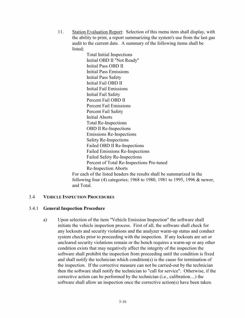
3-16
11. Station Evaluation Report: Selection of this menu item shall display, with the ability to print, a report summarizing the system's use from the last gas audit to the current date. A summary of the following items shall be listed;
Total Initial Inspections Initial OBD II "Not Ready" Initial Pass OBD II Initial Pass Emissions Initial Pass Safety Initial Fail OBD II Initial Fail Emissions Initial Fail Safety Percent Fail OBD II Percent Fail Emissions Percent Fail Safety Initial Aborts Total Re-Inspections OBD II Re-Inspections Emissions Re-Inspections Safety Re-Inspections Failed OBD II Re-Inspections Failed Emissions Re-Inspections Failed Safety Re-Inspections Percent of Total Re-Inspections Pre-tuned Re-Inspection Aborts For each of the listed headers the results shall be summarized in the
following four (4) categories; 1968 to 1980, 1981 to 1995, 1996 & newer, and Total.
3.4 VEHICLE INSPECTION PROCEDURES 3.4.1 General Inspection Procedure
a) Upon selection of the item "Vehicle Emission Inspection" the software shall initiate the vehicle inspection process. First of all, the software shall check for any lockouts and security violations and the analyzer warm-up status and conduct system checks prior to proceeding with the inspection. If any lockouts are set or uncleared security violations remain or the bench requires a warm-up or any other condition exists that may negatively affect the integrity of the inspection the software shall prohibit the inspection from proceeding until the condition is fixed and shall notify the technician which condition(s) is the cause for termination of the inspection. If the corrective measure can not be carried-out by the technician then the software shall notify the technician to "call for service". Otherwise, if the corrective action can be performed by the technician (i.e., calibration....) the software shall allow an inspection once the corrective action(s) have been taken.

3-17
b) If there exists no reason for the inspection to be terminated, the software shall
prompt the technician to enter his/her unique access code. Upon entry of the access code, the software shall verify whether the access code exists in the Technician Information table. The technician shall be given three chances to enter a valid access code. After an incorrect third entry, the software shall terminate the inspection process. After each incorrect entry the software shall inform the technician of the incorrect entry and to retry. A correct entry shall allow the inspection process to proceed.
c) If allowed to proceed, the software shall begin the HC Hang-up process and
prompt the technician to enter the vehicle identification number (VIN) either manually or scanned using the bar code scanner. If scanned using the bar code scanner, only a single entry is required. The software shall allow three attempts to enter the VIN correctly, afterwards it should terminate the inspection process. The software shall record in the EIS test record which method was used to enter the VIN.
d) If allowed to proceed, the software shall prompt the technician to enter the vehicle
license plate number either manually or scanned using the bar code scanner. If scanned using the bar code scanner, only a single entry is required. The software shall allow three attempts to enter the license plate correctly, afterwards it should terminate the inspection process. The software shall record in the EIS test record which method was used to enter the license plate.
e) 1. The software shall conduct an internal search on the hard drive for
any previous inspection containing the same VIN and/or license plate number. The software shall display on the screen a summary containing information of any matches found and allow the technician to select any one or to reject them all and proceed with a manual data entry. If the technician selects a matching record the software shall display the pertinent vehicle owner and vehicle specific information for review, possible modification, and acceptance by the technician as outlined in the following sub-section. If the technician chooses to reject all matches the software shall require the technician to manually enter the vehicle owner and vehicle specific information as outlined in the following sub-section.
2. If a match is found, the software shall display the pertinent vehicle owner and vehicle specific information for review, possible modification, and acceptance by the technician as outlined in the following sub-section.
f) If allowed to proceed, the software shall display any matching inspection records
found. Matching records available for review may be modified and accepted by the technician. The software shall require manual entry if a matching record was not found on the hard drive or if the technician rejected all matching records. The following information shall be displayed on two separate screens:

3-18
i. Vehicle Owner Information Screen. First Name,
Last Name, Address, County, City, Zip Code.
ii. Vehicle Specific Information Screen. Year,
Make, Model, Type, GVWR, Body Type, Cylinders, Transmission, Engine Displacement (liters), Odometer, Fuel Type. g) If allowed to proceed, the software shall make the determination as to whether to
conduct a TSI emissions or an OBD II inspection. All 1996 and newer gasoline powered vehicles with a GVWR less than 8,500 pounds, which are flagged in the VRT to undergo OBD II testing shall be subject to an OBD II inspection. Other vehicles shall undergo a TSI inspection.
1. If an OBD II inspection is required, the software shall follow the OBD II
inspection procedures outlined in the section OBD II Inspection Procedures. Afterwards the software shall continue with the inspection process outlined in the next sub-section. An HC Hang-up failure shall not restrict OBD II inspections, however, the analyzer shall inform the technician of the problem. 2. If a TSI inspection is required, the software shall not allow the
inspection to continue if the system failed the HC Hang-up process and shall notify the technician of the failure and whether or not he/she would like to wait for the HC Hang-up process to repeat.
If the TSI inspection is allowed to continue, the software shall follow the inspection procedures outlined in the section Visual Inspection Procedures, followed by those in the section Gas Cap Pressure Test Inspection Procedures and the Two-Speed Idle (TSI) Inspection Procedures. Afterwards the software shall continue with the inspection process outlined in the next sub-section.

3-19
h) If allowed to proceed, the software shall prompt the technician if he/she would like to conduct a safety inspection.
1. If the technician chooses to conduct a safety inspection, the software shall
follow the procedures outlined in the section Safety Inspection Procedures. Afterwards the software shall continue with the inspection process outlined in the next sub-section.
2. If the technician chooses not to conduct a safety inspection, the software shall continue with the inspection process outlined in the next sub-section.
i) If allowed to proceed, the software shall evaluate the test results for the emissions
test and Safety inspection, if applicable, based on the procedures in this specification and display a summary screen indicating the results of the vehicle inspection. The software shall require the technician to press a button to continue with the inspection process and print the VIR.
j) The software shall print the appropriate VIR as outlined in the section Vehicle
Inspection Report (VIR). 3.4.2 Two-Speed Idle (TSI) Inspection Procedures
Two-speed idle testing in the enhanced program areas shall be used when OBD II testing is not required. A passing TSI test shall be if the final HC and CO emissions readings, as specified in the appropriate test sequence, do not exceed the respective emissions limits.
All emissions readings for HC and CO shall be corrected for dilution using the Dilution Correction Factor (DCF) prior to evaluation of emissions test results. The CO2 and O2 emissions readings shall not be compensated for the DCF. The following testing/sampling sequences shall be available in the software at the time of certification/approval:
a) SEQUENCE #1: Testing period: 30 seconds for each stage First stage: 2500 RPM (± 10 %) Second stage: Idle RPM Basis for test results: Average of last 5 seconds of each sampling period. Units of test results: Concentration measurements: PPM HC, % CO, % O2 and
% CO2.
Test Sequence # 1 shall be used to test all vehicles except those mentioned under the test sequences below.
b) SEQUENCE #2:
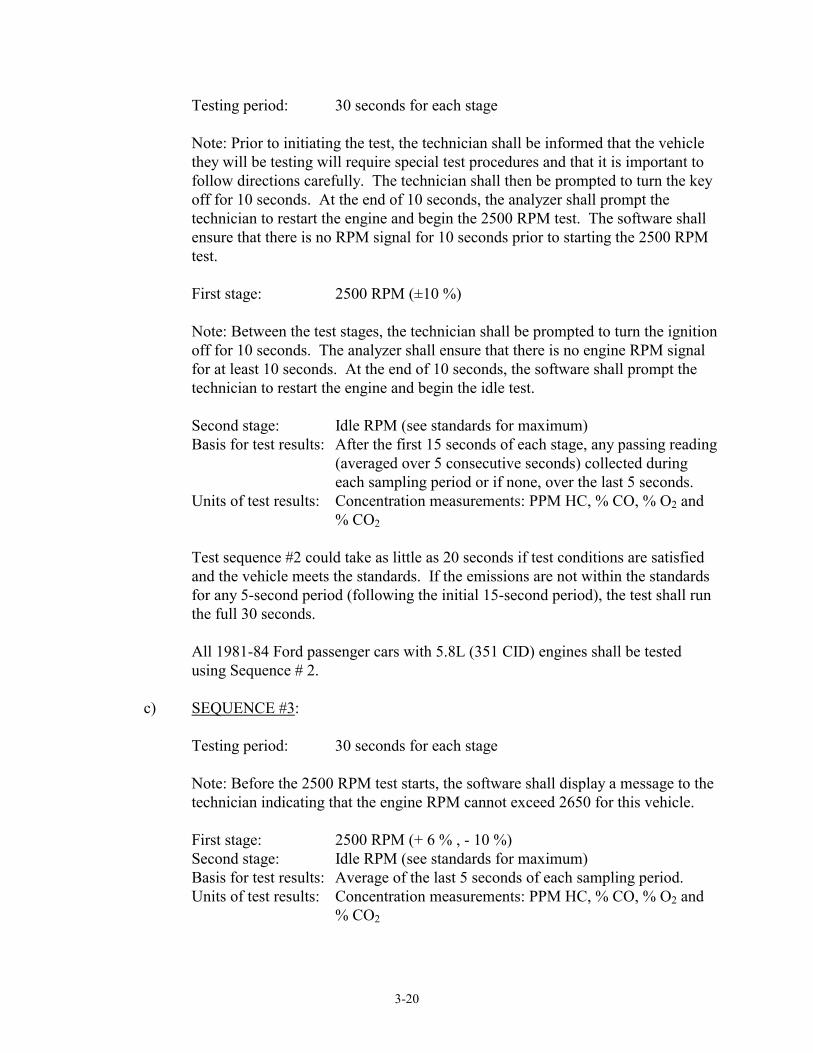
3-20
Testing period: 30 seconds for each stage
Note: Prior to initiating the test, the technician shall be informed that the vehicle they will be testing will require special test procedures and that it is important to follow directions carefully. The technician shall then be prompted to turn the key off for 10 seconds. At the end of 10 seconds, the analyzer shall prompt the technician to restart the engine and begin the 2500 RPM test. The software shall ensure that there is no RPM signal for 10 seconds prior to starting the 2500 RPM test.
First stage: 2500 RPM (±10 %)
Note: Between the test stages, the technician shall be prompted to turn the ignition off for 10 seconds. The analyzer shall ensure that there is no engine RPM signal for at least 10 seconds. At the end of 10 seconds, the software shall prompt the technician to restart the engine and begin the idle test.
Second stage: Idle RPM (see standards for maximum)
Basis for test results: After the first 15 seconds of each stage, any passing reading (averaged over 5 consecutive seconds) collected during each sampling period or if none, over the last 5 seconds.
Units of test results: Concentration measurements: PPM HC, % CO, % O2 and % CO2
Test sequence #2 could take as little as 20 seconds if test conditions are satisfied and the vehicle meets the standards. If the emissions are not within the standards for any 5-second period (following the initial 15-second period), the test shall run the full 30 seconds.
All 1981-84 Ford passenger cars with 5.8L (351 CID) engines shall be tested using Sequence # 2.
c) SEQUENCE #3: Testing period: 30 seconds for each stage
Note: Before the 2500 RPM test starts, the software shall display a message to the technician indicating that the engine RPM cannot exceed 2650 for this vehicle.
First stage: 2500 RPM (+ 6 % , - 10 %) Second stage: Idle RPM (see standards for maximum) Basis for test results: Average of the last 5 seconds of each sampling period. Units of test results: Concentration measurements: PPM HC, % CO, % O2 and
% CO2

3-21
All 1984 Jeeps with a 2.5L (150 CID) light-duty trucks shall be tested using test Sequence # 3.
d) SEQUENCE #4:
Testing period: 30 seconds for each stage
First stage: 2500 RPM (±10 %)
Note: A message shall be displayed to the technician indicating that the vehicle being tested will require special test procedures and that it is important that they follow directions carefully. The EIS shall display the following prompt only once, prior to the start of the emissions sampling:
DISPLAY PROMPT: IS THE VEHICLE FUEL INJECTED? (YES/NO) Programming Criteria: 1. If Yes, perform test sequence # 4. 2. If No, follow inspection sequence # 1. The technician shall be prompted to set the parking brake, press the brake pedal
and run the IDLE test with the transmission in DRIVE. When the idle test is complete, the technician shall be prompted to return the transmission to PARK.
Second stage: Idle RPM (see standards for max.)
Basis for test results: Average of last 5 seconds of each sampling period. Units of test results: Concentration measurements: PPM HC, % CO, % O2 and
% CO2
All 1984 Chrysler/Dodge/Plymouth passenger cars with a 2.2L, fuel-injected engines with automatic transmissions shall be tested using Sequence # 4.
e) SEQUENCE #5: Given the problems with the ZF automatic transmission, the County prefers that
the affected vehicles be tested at their dealerships. Accordingly, if the technician enters an A (for automatic) for the transmission type, and if the vehicle make, model and model year match BMW/Peugeot/Volvo criteria, the EIS shall display the following message:
BECAUSE OF THE POSSIBILITY OF TRANSMISSION DAMAGE TO THIS VEHICLE, THE COUNTY PREFERS THAT IT BE INSPECTED AT

3-22
ITS DEALERSHIP. IF YOU STILL WISH TO PERFORM THE INSPECTION, YOU MAY DO SO AT YOUR OWN RISK OR YOU MAY ABORT THE TEST.
Note: If the technician chooses to continue testing this vehicle, display the following message before beginning the test sequence.
BEFORE BEGINNING THE EMISSIONS TEST, MAKE SURE THE ENGINE IS AT NORMAL OPERATING TEMPERATURE. IF NOT, THE VEHICLE SHOULD BE DRIVEN UNTIL IT IS. DO NOT WARM THE ENGINE BY RAISING THE RPM ABOVE IDLE WHILE THE TRANSMISSION IS IN PARK OR NEUTRAL.
Perform idle test only (delete first stage).
Testing period: 30 seconds for idle stage Engine Speed: Idle RPM [Note: One stage only.] Basis for test results: Average of the last 5 seconds of the sampling period. Units of test results: Concentration measurements: PPM HC, % CO, % O2 and
% CO2
Note: All 1984-87 BMWs with automatic transmission, 1985-88 Volvo 740s with automatic transmission, and 1986-87 Peugeot 505s with automatic transmission shall be tested using test Sequence #5. If the engine has been changed to a different year, the special test sequence shall follow the year of the vehicle.
Example: * 1985 BMW with a ZF transmission and original engine uses test
sequence #5 and the emission standards for 1985. * 1985 BMW with a ZF transmission and a 1990 engine uses test
sequence #5 and emission standards for 1990. f) SEQUENCE #6:
Testing period: 30 seconds for each stage First stage: 2500 RPM (±10%) Second stage: Idle RPM Basis for test results: Stage 1: Average of last 5 seconds of sampling period. Stage 2: Same as stage 1; however, if the emissions are not within
the standards and the idle RPM was below 900, then the technician shall be prompted to rev the engine so that the idle speed is a minimum of 900 RPM (but not to exceed the manufacturer's specifications), and to continue the test for

3-23
another 30-second Second-Stage Idle Test. After the first 15 seconds of the repeated second stage, any passing reading (averaged over 5 consecutive seconds) collected during the sampling period, or, if none, the average reading over the last 5 seconds of the stage.
Units of test results: Concentration measurements: PPM HC, % CO, % O2 and % CO2
All 1985 Ford Ranger 2.3L (140 CID) light duty trucks and 1986 Ford Ranger and
Aerostar 2.3L (140 CID) light duty trucks shall be tested using test sequence #6. g) SEQUENCE #7: Testing period: 25 seconds for each stage
Note: Prior to beginning the first stage, the technician shall be informed that the vehicle he/she will be testing will require special test procedures and that it is important to follow directions carefully (this information shall not be displayed prior to the “second-chance” test if preconditioning is required). The technician shall then be prompted to ensure the tach lead is connected, start the vehicle and allow it to idle. At the end of 156 seconds, the analyzer shall prompt the technician to insert the probe and begin the 2500 RPM test. The software shall ensure that there is an RPM signal for 156 seconds prior to starting the 2500 RPM test. This 156-second warm-up shall not be required prior to the “second-chance” test if preconditioning is required.
First stage: 2500 RPM (±10 %) Second stage: Idle RPM (see standards for maximum)
Basis for test results: After the first 10 seconds of each stage, averaging shall begin. Any passing reading (averaged over 5 consecutive seconds) collected during each sampling period or if none, over the last 5 seconds.
Units of test results: Concentration measurements: PPM HC, % CO, % O2 and % CO2
Test Sequence #7 could take as little as 15 seconds if test conditions are satisfied and the vehicle meets the standards. If the emissions are not within the standards for any 5-second period (following the initial 15-second period), the test shall run the 25 seconds.
All 1985-1986 GM passenger cars with VIN-Y ("Y" in eighth position of the
VIN) engines shall be tested using Sequence # 7. 3.4.3 Vehicle Preconditioning Sequence For Two-Speed Idle Test

3-24
If a vehicle fails the TSI first chance and if all its emission readings are below 150% of their respective emissions limits, the analyzer shall instruct the technician to precondition the vehicle and run a second chance test. The EIS shall also use special test sequences for the second chance test if they were used for the first test. For example: if the EIS uses special test sequence #2 and the vehicle requires preconditioning, the EIS shall use special test sequence #2 for the second chance test. The EIS shall also follow any RPM restrictions that the special test sequence may require, i.e., a 1985 BMW with a ZF transmission shall NOT be preconditioned at high RPM. Based on the surveys conducted for the County, and on studies conducted on suspected pattern failures by the EPA, all model vehicles failing an initial test shall be preconditioned in the following manner, and re-tested:
DISPLAY PROMPT:
REMOVE THE EXHAUST PROBE FROM THE TAILPIPE.
a) Procedure #1: For All Vehicles Except Those Covered by Procedures 2 and 3 OPERATE THE VEHICLE AT 2500 ±300 RPM FOR THREE MINUTES WITH THE TRANSMISSION IN “PARK” OR “NEUTRAL.” AT THE END OF THE THREE-MINUTE PERIOD, ALLOW THE VEHICLE TO RETURN TO IDLE AND STABILIZE FOR 10 SECONDS, BUT DO NOT TURN THE IGNITION SWITCH OFF. INSERT THE PROBE INTO THE TAILPIPE. AT THE END OF THE 10-SECOND PERIOD, IMMEDIATELY BEGIN THE EMISSIONS TEST.
Programming Criteria For Procedure # 1
Within 30 seconds of having completed the three-minute portion of the preconditioning sequence, the technician shall release the throttle, insert the probe and return the engine to 2500 (±250) RPM. The 30-second time period shall begin when the engine RPM drops below 2200. The EIS shall provide prompts indicating when the technician should release the throttle, insert the probe and increase the engine RPM to the appropriate range as specified as soon as the probe has been inserted. The emissions test sequence shall begin as soon as the engine RPM reaches the appropriate range. The EIS shall display the time remaining before the preconditioning period will have to be restarted or the test aborted.
b) Procedure #2: For 1981-86 Fords and 1984-85 Honda Preludes

3-25
OPERATE THE VEHICLE AT 2500 ±300 RPM FOR 3 MINUTES WITH THE TRANSMISSION IN “PARK” OR “NEUTRAL.” AT THE END OF THE 3-MINUTE PERIOD, ALLOW THE VEHICLE TO RETURN TO IDLE AND IMMEDIATELY TURN THE IGNITION KEY OFF. INSERT THE PROBE INTO THE TAILPIPE. LEAVE THE IGNITION OFF FOR 10 SECONDS THEN RESTART THE ENGINE AND PROCEED IMMEDIATELY WITH THE EMISSIONS TEST.
Programming Criteria For Procedure # 2
Within 30 seconds of having completed the three-minute portion of the preconditioning sequence, the technician shall release the throttle, turn off the ignition for at least 10 seconds, insert the probe and return the engine to 2500 (±250) RPM*. The 30-second time period shall begin when the engine RPM drops below 2200. The EIS shall provide prompts indicating when the technician should release the throttle, turn the ignition key off, insert the probe, and to restart the engine and immediately increase the engine RPM to the appropriate range as specified. The emissions test shall begin as soon as the engine RPM reaches the appropriate range. The EIS shall display the time remaining before the preconditioning period will have to be restarted or the test aborted.
c) Procedure #3: For “ZF” Automatic Transmission
Given the problems with the ZF automatic transmission, the County prefers that the affected vehicles be tested at their dealerships. Accordingly, if the technician enters an A (for automatic) for the transmission type, and if the vehicle make, model and model year match BMW/Peugeot/Volvo criteria, the EIS shall display the following message:
BECAUSE OF THE POSSIBILITY OF TRANSMISSION DAMAGE TO THIS VEHICLE, THE COUNTY PREFERS THAT IT BE INSPECTED AT ITS DEALERSHIP. IF YOU STILL WISH TO PERFORM THE INSPECTION, YOU MAY DO SO AT YOUR OWN RISK. PRESS “ENTER” TO CONTINUE. IF NOT, PRESS “ESC” TO ABORT THE TEST.
For all 1984-1987 BMWs with automatic, 1986-87 Peugeot 505s with automatic, and 1985-88 Volvo 740s with automatic transmission.
*Emissions test RPM requirements may vary depending upon the test sequences.

3-26
If these vehicles fail the first chance, display the following message:
DUE TO POSSIBLE SERIOUS TRANSMISSION DAMAGE, DO NOT RAISE THE ENGINE SPEED ABOVE IDLE RPM WHILE THE TRANSMISSION IS IN NEUTRAL OR PARK. IF THE VEHICLE NEEDS TO BE PRECONDITIONED, DRIVE IT UNTIL IT HAS REACHED OPERATING TEMPERATURE.
The analyzer shall start the second chance test as soon as the EIS detects engine RPM within the idle RPM range. The EIS shall perform the emissions measurement at idle for 30 seconds. After the second chance, the EIS shall allow the technician to continue with the remainder of the inspection.
d) Programming Criteria For All Procedures:
The manufacturer shall provide for the capability to utilize as many different preconditioning procedures as can be contained in the analyzer. The preconditioning procedure number shall be recorded on the test record in the Preconditioning Procedure field.
1. For all procedures- The analyzer shall automatically instruct the technician
to initiate the preconditioning procedure whenever a vehicle fails the emissions test before the test can proceed. The analyzer software shall select and display only the appropriate preconditioning procedure based on the vehicle make and model year information entered by the technician.
2. For procedure # 1- A message shall be displayed instructing the technician
to remove the exhaust probe and increase the engine RPM to 2500 (±300) and hold it there for 3 minutes. The analyzer shall detect a signal in the proper range for 3 minutes within a 3-minute and 15-second period, with no single excursion exceeding 5 seconds. A message shall be displayed instructing the technician to adjust the engine RPM, restart the test or abort the test as appropriate if the RPM is outside of the specified limits. The preconditioning period shall begin as soon as the engine RPM is stable (for a period of 1 second) and in the proper range. To avoid loading the sample system with vehicle exhaust during the preconditioning process, the analyzer shall either back purge during the preconditioning sequence or prevent preconditioning if the probe is in the tailpipe. Preconditioning prevention could be determined by checking for emissions prior to or during the preconditioning sequence.
When the preconditioning period is complete, the technician shall be instructed to
allow the vehicle to return to idle and the analyzer shall ensure that the engine speed is reduced for at least 10 seconds, but no more than 30 seconds. If the engine speed is reduced for less than 10 seconds or more than 30 seconds, a message shall be displayed instructing the technician to either restart the
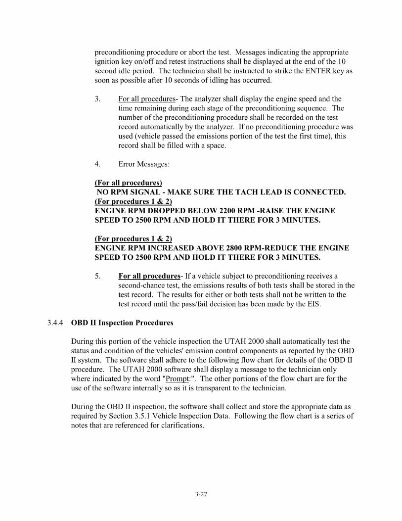
3-27
preconditioning procedure or abort the test. Messages indicating the appropriate ignition key on/off and retest instructions shall be displayed at the end of the 10 second idle period. The technician shall be instructed to strike the ENTER key as soon as possible after 10 seconds of idling has occurred.
3. For all procedures- The analyzer shall display the engine speed and the
time remaining during each stage of the preconditioning sequence. The number of the preconditioning procedure shall be recorded on the test record automatically by the analyzer. If no preconditioning procedure was used (vehicle passed the emissions portion of the test the first time), this record shall be filled with a space.
4. Error Messages:
(For all procedures) NO RPM SIGNAL - MAKE SURE THE TACH LEAD IS CONNECTED. (For procedures 1 & 2)
ENGINE RPM DROPPED BELOW 2200 RPM -RAISE THE ENGINE SPEED TO 2500 RPM AND HOLD IT THERE FOR 3 MINUTES.
(For procedures 1 & 2)
ENGINE RPM INCREASED ABOVE 2800 RPM-REDUCE THE ENGINE SPEED TO 2500 RPM AND HOLD IT THERE FOR 3 MINUTES.
5. For all procedures- If a vehicle subject to preconditioning receives a
second-chance test, the emissions results of both tests shall be stored in the test record. The results for either or both tests shall not be written to the test record until the pass/fail decision has been made by the EIS.
3.4.4 OBD II Inspection Procedures
During this portion of the vehicle inspection the UTAH 2000 shall automatically test the status and condition of the vehicles' emission control components as reported by the OBD II system. The software shall adhere to the following flow chart for details of the OBD II procedure. The UTAH 2000 software shall display a message to the technician only where indicated by the word "Prompt:". The other portions of the flow chart are for the use of the software internally so as it is transparent to the technician. During the OBD II inspection, the software shall collect and store the appropriate data as required by Section 3.5.1 Vehicle Inspection Data. Following the flow chart is a series of notes that are referenced for clarifications.
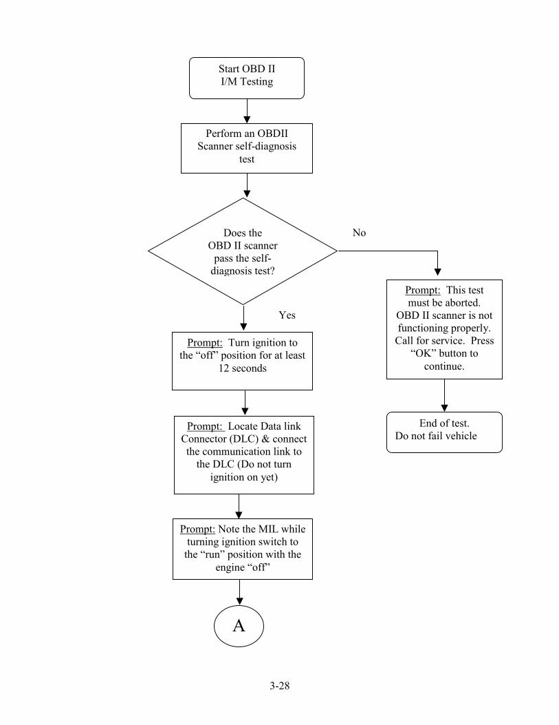
3-28
Start OBD II I/M Testing
Perform an OBDII Scanner self-diagnosis
test
Prompt: Note the MIL while turning ignition switch to
the “run” position with the engine “off”
Prompt: Turn ignition to the “off” position for at least
12 seconds
Prompt: Locate Data link Connector (DLC) & connect the communication link to
the DLC (Do not turn ignition on yet)
Prompt: This test must be aborted.
OBD II scanner is not functioning properly.
Call for service. Press “OK” button to
continue.
End of test. Do not fail vehicle
Does the OBD II scanner
pass the self-diagnosis test?
A
Yes
No

3-29
A
Vehicle fails test (see note 1)
Prompt: Start and leave the engine running and establish
communication with the on-board system
Prompt: No communication
with vehicle OBD II. Turn
engine switch to “off” and
disconnect the communications
link from the DLC. Press
“OK” button to continue.
Prompt: Does the MIL
illuminate?
Prompt: Did the MIL illuminate when
ignition switch was at “run” position with
the engine “off”?
Is the MIL (Mode $01, PID $01, Data A, bit 7)
commanded on?
Is the MIL illuminated
Vehicle fails test (see note 3)
Vehicle fails test (see note 4)
s
Has a successful communication with the on-board system been
established?
s
Vehicle fails test (see note 2)
End of OBD II Inspection
CNo
B
‘Count’ => 3?
Increment ‘Count’ by 1
Assign Variable ‘Count’Count = 0
s
No
No
No
No
No
Ye
Ye
Yes
Yes
Yes
Ye

303-
View Readiness Code status (Data Collection
only)
Retrieve DTCs using Mode $03 request. Provide DTCs with
description on the VIR for repair.
Prompt: End of OBDII Inspection.
Turn engine switch of “off” and disconnect the
communications link from the DLC. Press “OK” button to
continue.
Vehicle fails test.
Prompt: End of OBD II InsVehicle is not ready for OBD
The Vehicle needs to be opesuch a way as to “exercis
monitors. Turn engine switand disconnect the commun
link from DLC. Press “OK”continue.
Vehicle does not pass or fail Otest. Rather it is a “not rea
condition. (See note 5)
B C
Are all
End of OBD II Inspection.
Is (Vehicle ModeYear => 2001) an(Not Readys =< 1
Is (Vehicle ModelYear 1996 – 2000)and (Not Readys
=< 2)
End of OBD II Inspectio
No
Readiness Codes set to “Ready”?l d )? Yes
No
Prompt: End of OBD II
Inspection. Turn engine switch to
“off” and disconnect the
communications
s
No
pect II teratee” ach “icat butt
BDdy”
n
Ye
ion. sting.d in ll off” ions on to
II
Yes
link from the DLC. Press
“OK” button to continue.
Vehicle passes test.
End of OBD II Inspection.

3-31
a) Notes on OBD II Flowchart:
1. Note 1: The purpose of this step is to verify the On-Board Diagnostic
(OBD) system has control of the Malfunction Indicator Light (MIL) and the MIL is functional. Operation of the MIL varies between vehicle manufacturers. Key On Engine Off (KOEO) typically results in the MIL on steady, however, there are systems which will illuminate the MIL only briefly during KOEO. In either situation MIL presence and illumination capability has been established. If the vehicle fails the I/M test at this point, the vehicle inspection report should indicate the MIL problem should be repaired and also include information gathered during the remaining I/M test steps.
2. Note 2: It is important for the I/M testing personnel to verify proper
diagnostic equipment operation before failing the vehicle. If the diagnostic equipment is functional then the vehicle’s communication problem must be resolved.
Without communication between the OBD system and the test equipment the I/M test must be ended and the problem resolved before further interrogation of the vehicle can be performed. This step includes identification of Data Link Connector (DLC) tampering, serial data circuit problems and any other condition that would prevent the OBD system from communicating with the test equipment.
3. Note 3: I/M test failure is a result of MIL illumination even though the
OBD system has not commanded the MIL on, or has stored any Diagnostic Trouble Codes (DTCs); e.g., a serial data line failure between the OBD computer and the Instrument Panel.
4. Note 4: I/M test failure is a result of both the actual and commanded state
of the MIL. DTCs should be stored since the MIL is commanded on. A vehicle should not fail an I/M test when DTCs are stored but there is no MIL on; e.g., the DTC was stored by a loose gas cap which was subsequently tightened.
5. Note 5: Readiness Code status must be identified at this stage in the I/M
test to determine whether or not all emission control systems have been tested by the OBD system. If any one (or more) Readiness Code(s) are not set (“ready”) the OBD system has not yet completed testing of the system(s) and failures may be present but not yet identified. It is important to understand that the vehicle does not fail the I/M test at this point; no emission related faults have been identified. The current state of the vehicle’s emission control system is undetermined. The software shall print the two page "OBD II Drive Cycle" (see Appendix III) to inform the vehicle owner how to set the Readiness Codes.

3-32
The emission control systems and related components are tested under specific vehicle operating conditions. Therefore, to set the Readiness Codes the vehicle must be operated within these specific conditions (commonly referred to as “enable criteria”) for the OBD system tests to be performed. Once testing of an emission control system is complete, the related Readiness Code will be set (“ready”). When all Readiness Codes are set, the vehicle is ready for further I/M testing.
3.4.5 Visual Inspection Procedures
The EIS shall prompt the technician to enter the condition for each of the following visual inspection items;
1. Air Injection System, 2. Fuel Evaporation Control System, 3. EGR System, 4. PCV System, 5. Catalytic Converter,
The possible conditions for the visual inspection are pass, fail and not applicable. A fail item shall be the only cause for failing the visual inspection.
3.4.6 Gas Cap Pressure Test Inspection Procedures
The EIS shall prompt the technician to answer the following questions in this same sequence:
1. "Is the gas cap accessible? (Y/N)", 2. "Can the gas cap be removed? (Y/N)", 3. "Does it fit a standard adapter? (Y/N)".
If the technician answers “no” to any of the first two questions the software shall terminate the inspection process and print a VIR with all of the information collected thus far. However, if the technician answers “yes” to those same questions, the software shall not terminate the test. If the technician answers no to the third question the gas cap test shall not be conducted. However, if yes is answered to the final question then the pressure test shall be conducted. The software shall provide the appropriate prompts to facilitate the technician through the gas cap test process. At the conclusion of the gas cap test, the software shall evaluate whether the gas cap in question failed or passed the test.
a) If the gas cap failed the test, the software shall prompt the technician if the gas cap
was replaced with a new one. If so, the software shall prompt the technician to place the new gas cap on the tester and the software shall test the new gas cap. If the new cap fails the test then the software shall record this result in the EIS record. However, if the technician does not replace the gas cap with a new one the software shall keep the result and store it in the EIS record.

3-33
b) If the gas cap passes the test, the software shall keep the result and store it in the
EIS record.
At the conclusion of the gas cap test the software shall prompt the technician to remove the gas cap from the tester and to place it back on the filler neck of the vehicle.
3.4.7 Safety Inspection Procedures
The EIS shall prompt the technician to enter the Inspector Number, Inspection Fee and condition for each of the following safety items;
1. Wheel Lugs, 2. Emergency Brake, 3. Steering and Suspension, 4. Exhaust System, 5. Windshield Wipers/Washer, 6. Windshield/Tinting, 7. Other Glass, 8. Mirrors, 9. Headlights, 10. Other Lights, 11. Turn Signals, 12. Tires, 13. Horn, 14. Fuel System, 15. Other (i.e., body, seat, belts, ...).
The possible conditions for the safety inspection are pass, fail, repair, advisory and not applicable. If a technician enters a repair condition for any item, the software must prompt to enter the cost associated with the repair of the item(s) in question. An entry of repair or advisory for any of the safety inspection items shall require the software to prompt the technician to enter comments for the item(s) in question. During the course of the safety inspection the EIS shall also prompt the technician to remove a front and rear wheel and note which wheel was pulled for both, the left or right. Upon removal of the wheels, the technician shall be notified to inspect and measure the brake shoe thickness remaining on each set of brake shoe of those wheels pulled. The brake shoe thickness shall be measured and entered onto the system and the values shall range anywhere from 0 to a value of 32. There will be four (4) measurements taken, Front Wheel Primary, Front Wheel Secondary, Rear Wheel Primary and Rear Wheel Secondary. The lowest reading shall be used for pass/fail criteria. Values less than and equal to 1 shall be cause for failing the brake shoe safety inspection, thus failing the safety inspection. A fail for any safety inspection item shall be cause for failing the safety inspection. All data entered by the technician shall be stored to the Safety test record and sent to the HOST on the next HOST contact.
3.4.8 Repair Data Entry

3-34
The EIS shall prompt the technician to enter the date the repairs were made. The EIS shall not accept any repairs conducted before the initial test date. If the repairs were conducted prior to the initial test then the software shall inform the technician that the repairs are not valid to obtain a waiver. The EIS shall display a list of all repair categories and prompt the technician to select the category or categories of the system(s) which were repaired and/or service recommended. The codes for each of the two possible entries shall be stored in the repair record and sent to the HOST on the next call. The technician must be able to return to the list of major categories after each sub-category has been completed. Prior to exiting this function, the software shall summarize the information that was selected by the technician. This summary screen shall give the technician the option to accept/continue or modify the repair information. If the repair information is accepted then the software shall continue with the inspection process. Else, if the modify option is selected then the software shall go back and allow the technician to change the previous selections. All prior selections shall not be erased when the technician selects to modify the information.
All repair actions shall be documented on the vehicle inspection report (VIR), and stored in the repair record. The technician shall be required to sign on the VIR to document the repairs that have been performed to reduce emissions. The vehicle repair cost shall be printed on the VIR and the parts cost and labor cost of the repairs shall be entered in the PartsCost and LaborCost, respectively, fields of the repair record.
Categories
Spark Plugs/Wires Other Ignition Timing/Spark Advance Air/Fuel Mixture Adjustment Idle Speed Adjustment Choke System Other Carburetor Repairs Vacuum Leaks Fuel Injection System Other Induction System Air Filter Oil Change Thermostatic Air Cleaner PCV System Air Injection/Reaction System EGR System Fuel Evaporative System Catalytic Converter(s) Oxygen (O2) Sensor(s) MAP Sensor Mass Air Flow Sensor Coolant Temp. Sensor Throttle Position Sensor

3-35
Other Sensors/Switches Computer/PROM Internal Engine Repair Other Repairs/Unknown
After entry of eligible repair information the software shall allow the test to proceed and conduct the inspection as normal.
3.4.9 Pass/Fail Determination
The final inspection results shall be determined as follows:
a) Emission Inspection Pass Criteria If the OverallEmissionsResult, OverallGasCapTestResult, OBDIITestResult, and number 96 through 105 fields of the EIS test record all contain pass or N/A entries, then the vehicle shall pass the emissions portion of the inspection and a "P" shall be entered into the OverallTestResult field of the EIS test record. The vehicle shall pass the inspection and the EIS shall issue an emissions certificate.
b) Emission Inspection Fail Criteria
If the OverallEmissionsResult, OverallGasCapTestResult, OBDIITestResult, or number 96 through 105 fields of the EIS test record contain a fail or a tamper entry, then the vehicle shall fail the emissions portion of the inspection and a "F" shall be entered into the OverallTestResult field of the EIS test record. The vehicle shall fail the inspection and the EIS shall not issue an emissions certificate but may allow a waiver if the vehicle meets the waiver criteria.
c) Emission Inspection "Not Ready" Criteria
If the OBDIITestResult field of the EIS test record contains a "not ready" entry, then the vehicle shall not fail or pass the emissions portion of the inspection and a "R" shall be entered into the OverallTestResult field of the EIS test record. The vehicle shall not fail or pass the inspection and the EIS shall not issue an emissions certificate shall not allow a waiver.
d) Safety Inspection Pass Criteria
If field numbers 18 through 32 all contain either a pass, repair, advisory or N/A entry and both the FWMeasured and RWMeasured fields of the Safety test record each contain a value greater than 1, then the SafetyTestResult field of the Safety test record shall contain a "P" entry and the vehicle shall pass the safety portion of the inspection. The software shall issue a safety certificate.
e) Safety Inspection Fail Criteria
If any field numbers 18 through 32 contain a fail entry or either or both the FWMeasured and RWMeasured fields contain a value less than or equal to 1, then the SafetyTestResult field of the Safety test record shall contain a "F" entry and the vehicle shall fail the safety portion of the inspection. The software shall not issue a safety certificate.
3-36
3.4.10 Emissions and Safety Certificates of Compliance
The UTAH 2000 shall issue a certificate of compliance on pre-perforated paper provided by County. The certificate can then be used for registration of vehicle. The analyzer shall automatically keep track of the number of remaining certificates based on the total number purchased. The certificate number shall be printed on the VIR in both alpha numeric and UPRC one-dimensional barcode and shall be transmitted during the next HOST contact along with any other required inspection information. The certificate number shall be put in the CertificateNumber field of the EIS test record. The 10 digits shall be used sequentially for each emissions test requiring a certificate number. The certificate numbers shall be purchased by the UTAH 2000 unit from the HOST during a certificate purchase transaction. The UTAH 2000 software shall keep track of the unused certificate numbers issued to it by the HOST and notify the technicians when the certificate inventories are "running low".
3.4.11 Waivers
Upon completion of the inspection, if eligible repair information was entered and the vehicle failed for OBD II or TSI the software shall evaluate whether the vehicle is eligible for a waiver using all of the following criteria;
Repairs were conducted on or after the intial inspection date, Failed OBD II inspection or TSI, If a TSI inspection was conducted then current HC and CO readings shall not
exceed those of the previous inspection, and The software shall reference the Waiver Criteria Table for the corresponding
county-specific limits and criteria. The county-specific waiver criteria are provided in the Waiver Criteria Table.
3.4.12 Vehicle Inspection Report (VIR)
After display and review of the final test results, the EIS shall print the VIR. The VIRs shall adhere to the format provided in the sample VIRs in Appendix IV.
3.4.13 Training Mode
The UTAH 2000 shall have a TRAINING MODE feature that will allow a technician or student to go through the complete inspection procedure. This capability will be used by the manufacturers for training purchasers of the EIS, by EIS owners to train new employees, or for schools to train students. The training mode shall not require the use of a technician's access code or allow access to secured areas of hardware or software and will not communicate to the HOST. The display shall show a message throughout the
3-37
inspection that this is a training exercise and not an official test (no certificates shall be issued). The EIS shall print "NOT AN OFFICIAL INSPECTION" on the VIR.
The training mode test results shall be recorded and shall not be transmitted to the HOST at the next required communication session (i.e. next Inspection, data file refresh, etc.).
3.4.14 Dilution Correction Factor
The software shall apply a DCF to the HC and CO inspection emissions results. This dilution correction accounts for any exhaust sample dilution, intentional or unintentional, occurring during the emissions inspection process. The software shall calculate the DCF using the following procedure, and shall pre-select the formula appropriate to the vehicle's fuel type. If the calculated DCF exceeds 3.0, a default value of 3.0 shall be used. If the DCF falls below 1.0, then a default value of 1.0 shall be used.
a) Calculate “x” using the EIS measurements of CO and CO2 :
where [CO2]meas. and [CO]meas. are the final readings of each mode of the inspection (for example, 2500 RPM and idle).
b) Calculate the [ CO2 ]adj. using the following formulas.
For Gasoline
For Methanol or Ethanol:
For Compressed Natural Gas (CNG):
c) Calculate the corrected readings;
[ ][ ] [ ]x =
COCO + CO
meas.2
meas.2 meas.
[ ]adj.2CO = x
4.644+1.88x 100�
���
��
[ ]adj.2CO = x
4.73+1.88x 100�
���
��
[ ]adj.2CO = x
6.64+1.88x 100�
���
��

3-38
Corrected HC = Observed HC x DCF Corrected CO = Observed CO x DCF
3.4.15 Dilution
The software shall monitor the dilution in the exhaust throughout the duration of the TSI emissions sampling. The dilution (not to be mistaken for the DCF) is calculated summing the uncorrected CO and uncorrected CO2 emissions readings (CO + CO2). If the dilution value is below 6% then sample dilution is occurring and the emissions testing shall not proceed and cause a restart in the emissions testing procedure. However, CNG- and LPG-powered vehicles shall use a value of 4%.
3.4.16 Sample System Readiness (Zero & HC Hang-up) a) The analyzer shall be zeroed in accordance with Section 2.4.5 a) and b). b) The HC hang-up check will be done, according to Section 2.4.5 s), immediately
after the analyzer is zeroed and the ambient air is sampled. The zeroing and HC Hang-up process' shall be initiated after an inspection has been initiated and the technician access code has been accepted by the analyzer. The whole zero-ambient air-HC hang-up sequence shall run in background while the inspection process continues but before the TSI. If the hang-up check is not completed before the technician is ready to start the tailpipe test, the EIS shall display the following message:
DISPLAY PROMPT:
HC HANG-UP CHECK IN PROGRESS.
If the hang-up check is not successfully completed in 150 seconds from the start of the hang-up check, the EIS shall display the following message:
DISPLAY PROMPT:
POSSIBLE DIRTY PROBE, HOSE OR FILTER. VERIFY THAT THE PROBE TIP IS NOT NEAR AN EMISSIONS SOURCE AND THAT THE PARTICULATE FILTER IS NOT DIRTY. DO YOU WANT TO RETRY OR ABORT THE INSPECTION.
c) The software shall not allow the inspection to continue before the system passes
the HC hang-up check unless it has been determined that the inspection will be an OBD II test.
3.4.17 Aborts
The software shall record the following types of aborts. Any information already gathered prior to the abort shall be written to the test record and stored on to the hard
3-39
drive. The technician shall have the option to abort any inspection at any time with the selection of the <Esc> or a function key. Aborted inspection records shall be sent to the HOST. If an abort occurs, then the software shall select the most appropriate abort code, write it to the AbortCodeNumber field in the EIS test record, and place an "A" to the OverallTestResult field of the EIS test record.
Code Description
01 Inspector license expired 02 Incorrect VIN 03 After HOST contact 04 Gas cap not accessible 05 Gas cap can not be removed 06 After visual inspection but prior to gas cap test 07 During OBD II inspection 08 During TSI inspection 09 During Safety inspection
3.5 VEHICLE INSPECTION INFORMATION 3.5.1 Vehicle Inspection Data
a) Data Collection, format and Storage: Following is a brief description describing all of the data, including TSI, OBD II, safety, gas cap, repair, calibration, lockout, Vehicle Reference Table (VRT), and emissions limits data that shall be collected and stored onto the hard drive. The data described in this section is divided into several different subsets referred to as records and/or tables. Each record contains data for each of the major tasks of the UTAH 2000 units. The records are sorted by alphabetical order in Appendix II. Some information will be generated by the UTAH 2000 units and the rest will be supplied by the HOST. Those fields designated by the fields "Sent to HOST" and "Sent by HOST" with a "X" signify that the data will be generated at the EIS unit or the HOST, respectively and transferred during the inspection's HOST communication session. Some fields may be generated from both sources and are designated by a "X" in both fields. The "RefreshAll" designates the data which shall be transmitted during a non-inspection HOST session. The "RefreshAll" process is used only for updating the individual EIS units with the latest information, as in the initialization process. All field formats shall be adhered to when storing on to any of the drives and during the HOST transmission. Important Note: The manufacturer shall adhere to the possible entries for each field(s) when specified in this specification. Appendix II contains the possible entries for many fields. When possible entries are absent/omitted in this specification it shall be the responsibility of the manufacturer to develop the codes and possible entries upon consultation and approval of the County.
1. Audit Record (Audit): During a County gas audit, the software shall record the following information in the prescribed format and store the information onto the hard drive and floppy drive. These records shall be

3-40
sent to the HOST during the inspection HOST session. Once sent to the HOST the record shall be removed from the floppy drive but not from the hard drive. Only the last fifty (50) Audit records are required to be kept in storage on the hard drive.
2. Calibration Record (Calibration): This record shall be generated during
each UTAH 2000 unit calibration. All records must be sent to the HOST, one time only, on the initial call of the following inspection. Prior to being sent the test records must be stored on both the hard drive and floppy disk. Once sent to the HOST, the record shall be removed from the floppy disk. The EIS shall keep in storage on the hard drive, at the very least, the last one hundred (100) calibration records.
3. Certified Emissions Repair Facility Record (CERF): This record will be
generated and sent by the HOST. This record contains information on all repair facilities certified by the County to conduct repairs on emissions components. This record shall be referenced by the software before allowing repair information to be entered. Any repairs from facilities not found in this list or with an expired license will not count towards the inspection. The CERF records shall be sent by the HOST during a "RefreshAll" session.
4. Certified Emissions Repair Technician Record (CERT): This record will
be generated and sent by the HOST. This record contains information on all repair technicians certified by the County to conduct repairs on emissions components. This record shall be referenced by the software before allowing repair information to be entered. Any repairs from technicians not found in this list or with an expired license will not count towards the inspection. The CERT records shall be sent by the HOST during a "RefreshAll" session.
5. City Zip Code Record (CityZip): This record will be generated and sent
by the HOST. This record contains zip code related information. This record shall be used by the software for cross referencing county codes, county names, city names, and city zip codes. Included in each record is the field "GasCapTest" which shall be used by the software to determine whether a vehicle is required to undergo the gas cap pressure test. These records shall be sent by the HOST during a "RefreshAll" session.
6. County Information Record (CountyInfo): This record will be generated
and sent by the HOST. This record contains technical center phone numbers for each county. This record shall be used by the software for cross referencing county codes and the technical center phone numbers. These records shall be sent by the HOST during a "RefreshAll" session.
7. Technical Service Bulletin (TSB): This record will be generated and sent
by the HOST. This record contains technical service bulletins for the

3-41
technicians. The TSB shall be displayed by the software upon receiving the TSB. The software shall allow the technicians to review on screen and print each TSB. The last five (5) TSB's received shall be stored on the hard drive so that technicians may print or review the last five (5) at a later time. The TSB records shall be sent by the HOST during an inspection HOST session.
8. Vehicle Inspection Record (EIS): This record shall be generated and sent
by the UTAH 2000 units to the HOST. This record shall contain information from the vehicle inspection. All records must be sent to the HOST, one time only, on the initial call of the following inspection HOST session. Prior to being sent the test records must be stored on both the hard drive and floppy disk. Once sent to the HOST, the record shall be removed from the floppy disk. The EIS shall keep in storage on the hard drive, at the very least, the last one thousand (1,000) vehicle inspection records.
9. Vehicle Inspection Certificate Inventory Record (InspCertInventory): This
record will be generated and sent by the HOST. This record contains information on the remaining vehicle inspection certificate inventory of the individual UTAH 2000 unit. The software shall reference the inventory records and select the lowest un-issued certificate number prior to issuing a certificate. Once a certificate has been issued it shall not be re-used for any other inspection. The certificate number shall be printed on the Certificate. The InspCertInventory records shall be sent by the HOST during a HOST "RefreshAll" session. The "UnitPrice" and "TotalPrice" fields will only be filled when a purchase is made using the "BuyCerts" HOST session.
10. Lock Out Record (LockOut): This record will be generated and sent by
both the HOST and the UTAH 2000 units. This record shall contain lock out information for the individual EIS units. The LockOut record shall be sent to the HOST at the beginning of an inspection HOST session and returned by the HOST prior to terminating the same session. Any lock outs returned by the HOST shall be set by the software for that particular EIS unit. The LockOut record shall be stored on both the hard drive and floppy drives at all times. Any current lock outs set by the EIS or HOST shall be contained within this record.
11. OBD II Fault Code and Readiness Record (OBDIIFC): These records will
be generated and sent by the HOST. This record contains information used by the software for cross referencing the OBD II fault and readiness codes with their text translation. The FaultReadinessCode field contains information whether the fault code is cause for inspection failure or not. These records shall be sent by the HOST during a "RefreshAll" session.

3-42
12. Repair Record (Repair): This record shall be generated and sent by the UTAH 2000 units to the HOST. This record shall contain information from the vehicle repairs. All records must be sent to the HOST, one time only, on the initial call of the following inspection HOST session. Prior to being sent the Repair records must be stored on both the hard drive and floppy disk. Once sent to the HOST, the record shall be removed from the floppy disk. The EIS shall keep in storage on the hard drive, at the very least, the last one thousand (1,000) Repair records.
13. Safety Record (Safety): This record shall be generated and sent by the
UTAH 2000 units to the HOST. This record shall contain information from the vehicle safety inspection. All records must be sent to the HOST, one time only, on the initial call of the following inspection HOST session. Prior to being sent the Safety records must be stored on both the hard drive and floppy disk. Once sent to the HOST, the record shall be removed from the floppy disk. The EIS shall keep in storage on the hard drive, at the very least, the last one thousand (1,000) Safety records.
14. Vehicle Safety Inspection Certificate Inventory Record
(SftyCertInventory): This record will be generated and sent by the HOST. This record contains information on the remaining vehicle safety inspection certificate inventory of the individual UTAH 2000 unit. The software shall reference the inventory records and select the lowest un-issued certificate number prior to issuing a certificate. Once a certificate has been issued it shall not be re-used for any other inspection. The certificate number shall be printed on the Certificate. The SftyCertInventory records shall be sent by the HOST during a HOST "RefreshAll" session. The "UnitPrice" and "TotalPrice" fields will only be filled when a purchase is made using the "BuyCerts" HOST session.
15. State Information Record (States): These records will be generated and
sent by the HOST. This record contains information used by the software for cross referencing the state codes with their text translation. These records shall be sent by the HOST during a "RefreshAll" session.
16. System Record (System): This record will be generated and sent by the
HOST. This record will contain system information for the individual EIS units. The record shall be sent by the HOST during an inspection HOST session.
17. Emissions Limits Record (Table3): These records will be generated and
sent by the HOST. This record contains the emissions limit information used by the software for evaluating the emissions test results. These records will be sent by the HOST during a "RefreshAll" session.
The emissions standards (Table3) table shall reside in the EIS and receive updates from the HOST. The EIS shall look into Table3 for emission cut
3-43
points. Table3 shall also have a version number. Upon implementing the new table, the old version shall be purged. Additional standards categories may be added at a future date. Based on the vehicle information entered, the EIS shall determine the emissions test standards for the vehicle being tested. For each vehicle, the table will contain HC and CO Pass/Fail emissions for the two-speed idle tests. Print these emissions values on the VIR. Table3 values and the criteria for selecting categories shall be designed in a manner that allows for easy modification or addition.
The ESC for the vehicle under test shall be written to the Emission Standards Category field of the test record.
18. Tamper History Record (Tamper): This record shall be generated and sent
by the UTAH 2000 units to the HOST. This record shall contain tamper information from the each individual unit. All records must be sent to the HOST, one time only, on the initial call of the following inspection HOST session. Prior to being sent the Tamper records must be stored on both the hard drive and floppy disk. Once sent to the HOST, the record shall be removed from the floppy disk. The EIS shall keep in storage on the hard drive, at the very least, the last one hundred (100) Tamper records.
19. Tamper Limits Record (TamperCriteria): These records will be generated
and sent by the HOST. The record contains information used by the software for determining the tampering criteria for each County. These records shall be sent by the HOST during a "RefreshAll" session.
20. Station Technician Information Record (TechInformation): This record
will be generated and sent by the HOST. This record contains information on all inspection technicians certified by the County to conduct inspection at that individual inspection station. This record shall be referenced by the software before allowing the vehicle inspection from proceeding. Upon initiation of a vehicle safety or I/M inspection the software shall prompt the user for their access code designated in the "AccessCode" field of this record. If the access code is not found in any of these records the inspection shall be aborted. The CERT records shall be sent by the HOST during a "RefreshAll" session.
21. Vehicle Reference Table Record (VRT): This table shall be generated by
the HOST and sent during a "RefreshAll" session. This record must be stored onto the hard drive and referenced by the software for finding vehicle information during data input. This record will be updated on a yearly basis or as new vehicle model years are introduced into the fleet. Each record in the dataset will contain information for every particular make, model, year, engine size ... vehicle currently in circulation. The VRT shall be referenced by the software to determine whether OBD II

3-44
testing is applicable. The "OBDIITest" field provides information whether a vehicle is subject to an OBD II inspection.
22. Waiver Cost Limits Record (WaiverCriteria): These records will be
generated and sent by the HOST. The record contains information used by the software for determining the applicable waiver cost limits for each County. These records will be sent by the HOST during a "RefreshAll" session.

4-1
SECTION 4 CENTRAL COMPUTER SYSTEM SPECIFICATION This section outlines the performance and functionality of the Central Computer System (CCS) for the UTAH 2000 I/M program. The Contractor shall be responsible for designing, implementing, operating and maintaining the hardware, software and peripheral equipment necessary to accept and store data created at UTAH 2000 inspection stations. The CCS shall have a dedicated, secure connection so that the UTAH 2000 units may contact from the testing facilities and to facilitate the flow of data between the inspection stations and the CCS data repository. All UTAH 2000 units shall connect to the CCS through an independent and secured means using the internally housed modems and dedicated telephone lines. All requirements in the Central Computer System Specification section must be addressed in sufficient detail to allow the County to determine how the Contractor will meet each requirement. 4.1 GENERAL
All components including hard drives, memory, I/O devices and media subsystems used in the CCS shall be of types and brands that are presently in common usage. The host computer(s) and all CPU devices connected within the CCS must operate using a common operating system without modification. Multiple redundant systems or system clusters are an acceptable method of achieving desired performance and redundancy. The County may allow deviations upon approval. a) CCS Capacity
The CCS must have the capacity to annually handle, manage and store one (1) million vehicle record files, approximately 1.2 million emissions tests which includes retests, and allow for an estimated growth rate of 6%. This system must be able to handle 4,000 transactions per hour.
b) CCS Expandability The CCS must be expandable to allow for future expansion to support increased load, transactions, vehicle records, data storage requirements and/or application development.
c) CCS Reliability/Availability The CCS shall be fault tolerant and shall be accessible 24 hours a day, 7 days a week excluding scheduled maintenance downtime(s).
d) Backup System The CCS shall include a reliable data backup system capable of restoring the system and data to working order with minimal data loss and service interruption. The backup media must be stored in an off-site location.
e) Security Due to the nature of the data being transmitted, security is a very serious issue to be considered by the Contractor. 1. The CCS must be able to make secure connections between itself and the
remotely located UTAH 2000 units, remotely located County personal computer (PC) or any other County authorized computers.

4-2
2. The CCS must have multiple levels of security to protect applications and data files from unauthorized access, modification or deletion. The multiple levels of access shall reflect different types of users.
3. The CCS must have physical security measures to protect applications and data files from intruders, electrical power fluctuations or failure, fire damage, water damage or other acts of God.
4.2 HARDWARE REQUIREMENTS
a) Architecture
An architectural design of the CCS and all major components is required. It must describe the design of the network between the inspection stations and the CCS, and it must include any local area network within the CCS.
b) Year 2000 Compliance All computer systems, sub-systems, components, networks, and/or computer equipment including hardware, software, firmware and operating systems to be utilized by the Contractor for this project must be Year 2000 Compliant. All dates must be represented and interpreted by four (4) digit years.
c) Database Sub-System The heart of the CCS is the Database subsystem. This is where the applications and data repository will be stored and accessed. This system or group of systems must be capable of responding to the many data requests from inspection stations and the remotely located County PC's. The minimum requirements are as follows:
1. Hardware A. Processors
The Database Sub-System must be able to support multiple processors or distributed systems.
B. Storage Capacity The Database Sub-System must be able to store one (1) million vehicle record files, approximately 1.2 million emissions tests which includes retests, and allow for an estimated growth rate of 6%. This system must be able to handle 4,000 transactions per hour. The minimum hard-drive capacity is expected to be 35 GB, and the hard-drive subsystem must employ some sort of hot swappable redundant array of disks.
C. Memory The Database Sub-System must contain sufficient RAM and Cache Memory to quickly and efficiently handle the volume and flow of transactions listed above.
D. Operating System The Database Sub-System must be controlled by a robust, multi-tasking operating system with built-in security features such as access-level control implementing user identification numbers and blind entry passwords.

4-3
E. Documentation The Contractor shall supply documentation and/or user manuals for all hardware and software including manufacturer contact information of any outside or third party software integrated into the system.
2. Database Engine Commercially supported product with technical support from the manufacturer available 24 hours a day, 7 days a week. The DataBase Management Systems (DBMS) must support parallel, symmetric server architecture with automatic load balancing across multiple processors.
3. Secure Transactions All transactions with the inspection stations, the County’s remote PC's and any County authorized computers must be secure. Therefore, as a minimum the data must be encrypted using a private key or other means.
d) Backup System The CCS shall include a reliable data backup system capable of restoring the system and data to working order with minimal data loss and service interruption. The system must be capable of backing up all data and applications. A Master Backup Plan must be supplied outlining the procedures for daily, weekly and monthly back-ups, media rotation, and off-site storage and retrieval procedures. The Master Backup Plan shall include, at a minimum, the procedures for daily backup, off-site storage of all applications and data files, and data retrieval procedures.
e) Un-interruptible Power Supply The CCS must be protected by an un-interruptible power supply (UPS) to isolate the system from power spikes, surges, fluctuations, brown-outs and complete power loss situations. The UPS must be able to maintain system operation for a minimum of one (1) hour for proper shutdown of the system without loss of data. The UPS must have a communications link and communications software that is compatible with the CCS' operating system and application software. Through this link, the UPS shall notify the CCS when power has been interrupted so that it may initiate a safe system shutdown automatically.
f) Automated Emergency Notification The CCS shall employ a method which automatically and immediately notifies through the use of a paging system or some other reliable method a local primary and secondary representative of any emergency or potential emergency situation. This feature shall have the capability to be activated by the CCS hardware and/or software in case of an emergency. The paging system shall contact the primary and secondary representatives when an emergency arrives. A plan shall be set into place whereby the primary, the secondary or both representatives shall respond to the emergency within a period of time acceptable to the County. The County must also be informed of such an emergency.
4.3 DISASTER RECOVERY

4-4
A disaster recovery plan shall be provided outlining the steps to be followed in the case of a disaster or failure of the CCS. In the event of an outage of the system, the Contractor must implement the disaster recovery plan approved and on file with the County. The Contractor must notify the County immediately of the disaster and the system must be operational again within one calendar day (24 hours). The Contractor’s design shall address: a) Scope of the disaster recovery plan (i.e. list all likely events this plan would
cover), b) Major steps of the disaster recovery plan, c) Precautions taken to prevent possible downtime and data loss, d) List of redundancies and fault tolerance built into the system, e) Ability of Contractor to implement plan immediately, f) Estimate of time required to make system operational.
4.4 SOFTWARE REQUIREMENTS
a) Automatic Report Generation The HOST software shall provide a method by which authorized remote PCs may
access periodic reports. The reports shall consist of; 1. Repeat of the "Station Evaluation Reports" defined in Section 3 County
Menu with the addition of categories by county, station, and overall for any user selected year, month or day,
2. Repeat of the "Monthly Station Inspection Report" defined in Section 3 Additional Site Specific Software for a user selected station and any user selected year, month or day,
b) User Access Levels
The HOST software shall provide a method by which only authorized UTAH 2000 units and remote PCs may access the HOST. Access Codes for the Remote County PCs shall require a double-blind entry while a method shall be developed by the manufacture to establish a secure login procedure for the UTAH 2000 units. The software shall offer the following user access levels; 1. User Level 1 Access:
��Modification of all reference tables or records (i.e., all tables/records but the Audit, Calibration, EIS, Repair, and Safety information which is generated by the analyzers) sent to the analyzers by the HOST,
��Ability to set and reset lockouts for any analyzer, ��Downloading and printing of reports locally, ��Downloading of data from time intervals specified by the user.
2. User Level 2 Access:
��Ability to set and reset lockouts for any analyzer, ��Downloading and printing of HOST-generated reports locally, ��Downloading of data from time intervals specified by the user.

4-5
3. User Level 3 Access: ��Downloading and printing of reports locally.
4. User Level 4 Access (UTAH 2000 units only):
��Communication with authorized UTAH 2000 units for transferring test information and reference tables to and from the HOST.
c) Data Downloads For AD-Hoc Reporting
The HOST software shall provide a method by which authorized remote PCs may access the HOST and download different test data from user specified time periods. The software shall be designed in such a way as to allow the user the flexibility to specify which field from the selected test records to download. This last feature will limit the time needed to transfer data without transferring unwanted information.
d) UTAH 2000 HOST Communications
The HOST software shall provide a method by which authorized UTAH 2000 units may contact the HOST and download vehicle-specific and analyzer-specific information as defined in Appendix II. During a normal HOST contact the UTAH 2000 units will transfer the information marked by the SendToHOST field in Appendix II. Likewise, the HOST shall return to the UTAH 2000 units that information marked by the SendByHOST field in Appendix II. In a second type of HOST contact, the HOST shall send the UTAH 2000 units that information marked by the RefreshAll field in Appendix II. It shall be the responsibility of the manufacturer to establish the communications protocol between the HOST and UTAH 2000 and the remote County PCs described in the next section.
4.5 REMOTE COUNTY PERSONAL COMPUTER REQUIREMENTS
a) General The Remote County Personal Computers (RCPC) will be located in various, but limited number of, County offices. Their main function is to enable restricted County employees access to the CCS to download and print reports on a local printer. In addition, these remote PCs will allow several different levels of access into the HOST computer. These levels are discussed in this section of the specification. The RCPCs must also be capable of downloading subsets of data from the CCS for Ad-Hoc analysis outside the scope of this work.
b) Hardware Requirements 1. Year 2000 Compliant
The RCPCs shall be year 2000 compliant. 2. Processor
The RCPCs shall contain an Intel Pentium II or equivalent 400 MHz processor

4-6
or faster, minimum of 32KB Level 1 Cache and minimum of 512KB Level 2 Cache.
3. Operating System The RCPCs shall have Windows 95 or Windows 98 as the operating system.
4. Memory The RCPCs shall have, at a minimum, 128MB RAM and expandable to 256MB RAM.
5. Expansion Slots The RCPCs shall have a minimum of 3 PCI and 2 ISA expansion slots for possible future expansion.
6. I/O Ports The RCPCs shall have a minimum of
-One (1) serial port -One (1) parallel port -One (1) PS/2 port -Two (2) USB ports
7. Disk Drives The RCPCs shall have the following disk drives:
-6GB or larger internal hard disk -1.44MB 3.5” floppy drive -16X or faster CD-ROM drive.
8. Video The RCPCs shall have an SVGA video display capable of generating 1024x768 resolution with 256 colors. The low glare screen shall have a 16” or greater diagonal viewing area and a .28mm or smaller dot pitch.
9. Multimedia Accessories The RCPCs shall be equipped with a sound card and speakers for multimedia presentations.
10. Modem The RCPCs shall have a 56Kbps V.90 or Kflex compatible internal or external analog modem.
11. Backup The RCPCs shall have a backup system capable of backing up the entire system in an unattended mode.
12. Power Supply The RCPCs shall have a UL approved 200 watt or greater power supply. The power supply must be attached to a high quality surge suppressor with modem protection.
13. User Inputs The RCPCs shall have an industry standard 104-key keyboard and a standard mouse with mouse pad.
14. Other Software -Office productivity suite containing a word processor, spreadsheet and database program such as Microsoft Office Professional or Lotus SmartSuite.

4-7
-Virus scanning software 15. Printer
The RCPCs shall have a quality laser printer attached. The printer must be capable of printing 6 pages per minute on 8.5” X 11” paper at 96 characters per line, and six (6) lines per pitch.
c) Software Requirements
The software which communicates these remote PCs to the HOST shall be password protected based on the three different levels of user permissions defined in this section. Upon running the software the user shall be prompted to enter his/her access code and ID. Only authorized access codes and IDs shall be accepted by the software. These access codes and IDs shall be stored in the remote PCs in such a way that prevents unauthorized modifications. The software shall run of the remote PCs yet shall allow use of the PC in its "normal" (allow usage of other software applications) capacity (i.e., Windows Office ®, etc.). The software shall be designed in such a way that the user interface is easy to move about from feature to feature and must be approved by the County. This software shall also monitor the system to determine if a period of more than 20 minutes have gone by without any action. Upon detection of the 20 minute idle the software shall automatically logout or prompt for re-entry of the access code and ID.

5-1
SECTION 5 DOCUMENTATION, SERVICE AND WARRANTY 5.1 GENERAL
The following items shall be included with the delivery of each UTAH 2000 unit to the inspection stations:
a) Instruction manual, securely held in a binder (or other suitable container) made to
with stand normal use in the garage environment, and b) A copy of the warranty, and c) A copy of the annual service agreement, and d) A copy of the extended service agreement if purchased, and e) Four extra sets of particulate filter elements, and f) Special adjustment tools if needed for calibration of the analyzer, the fuel cap
tester and any other integral device, if applicable. 5.2 INSTRUCTION MANUAL
The instruction manual accompanying each UTAH 2000 unit shall contain the following minimum information:
a) Background information describing how vehicular emissions are formed during
the combustion process, the general types of controls that are used on vehicles and what negative health impacts can result from vehicle emissions;
b) Functional diagrams (mechanical and electrical); c) Accessories and options (included and/or available); d) Model number and identification markings and locations; e) Maintenance procedures and frequencies recommended by the manufacturer. The
services that should be performed only by the manufacturer shall be clearly identified;
f) Gas calibration/leak check procedures as well as calibration procedures for the fuel cap tester and any other integral device;
g) Brief description with a subject index of the inspection/test procedures as they pertain to the EIS prompts;
h) Brief description of emission analyzer operating principles; i) Information provided shall include a listing of warranty repair stations by name,
address and phone number; and j) Name, address and phone number of the manufacturer's representative in charge
of sales and service personnel for the company in Utah. 5.3 UTAH 2000 WARRANTY AND SERVICE MAINTENANCE CONTRACT a) The cost of the UTAH 2000 shall include a one-year, transferable warranty
covering parts and labor. In addition, at the time of original sale, the manufacturer shall offer optional yearly extended warranties to be in addition to cost of the EIS.

5-2
Warranty provisions protecting the interest of the buyer shall include: 1. Location, phone number and address of the repair centers throughout the
state. These shall be an adequate number of qualified repair technicians and an adequate number of repair locations conveniently located to efficiently and promptly meet statewide service needs. The response time established by the manufacturer may be longer for a lower purchase price or shorter if the price is higher. All response time and cost provisions shall be clearly indicated in the warranty provisions.
2. Name of the manufacturer's representative closest to each franchised
service center - if not a factory service center. 3. Coverage of at least all of the hardware and software contained inside the
tamper resistant analyzer cabinet, the computer keyboard and monitor and the fuel cap tester. A description of specific parts and labor covered by the provisions of the warranty shall be provided to the purchaser. In addition, the warranty shall itemize the cost of labor which are not covered by the warranty.
To ensure that purchasers are properly notified regarding the cost and
provisions of the warranty, the UTAH 2000 units shall not be delivered until a copy of the warranty has been signed by the purchaser and a company representative. Service response time and loaner provisions shall be initialed by the purchaser. A copy of the signed warranty shall be provided to the purchaser and a copy filed by the company.
b) The manufacturer shall make available an annual service contract covering, as a
minimum, all of the items provided with the analyzer and the fuel cap tester.
Service contract provisions protecting the interests of the buyer shall include: 1. The necessary level of service to ensure that the UTAH 2000 unit
functions properly within the operating conditions listed in this specification. Such items as filters, disk drive cleaning and alignment, analyzer bench service, and pump maintenance are typical service maintenance items.
2. The manufacturer is responsible for specifying the frequency of
performance. 3. The manufacturer shall include in the annual service/maintenance contract
the cost of making the necessary software changes.

5-3
4. The manufacturer or his sales representative must notify the County of the cost for this service as a condition of certification and include projected increases.
5. The information in Items 1 - 4 above must also be made available to the
potential buyer of a UTAH 2000 before purchase or lease. c) The following provisions apply to both the warranty and service maintenance
contract: 1. Any change to the warranty or service contract must be approved by the
County. 2. The UTAH 2000 owner shall be provided a cost estimate prior to the
performance of any service or maintenance unless the work is covered by the warranty or service contract. Regardless of whether or not the work is covered by the warranty or service contract, the owner shall be provided a detailed description of the work performed when the job is completed. In addition, the manufacturer shall include a toll-free telephone number for the owner of the analyzer to call if he/she wants to complain about the work performed, the courtesy or competency of the manufacturer's technician or any other aspect of the warranty or service contract.
3. Manufacturers shall provide a station with a loaner UTAH 2000 unit if the
station's EIS is out of service for more than 3 "normal work days". Loaner units shall be calibrated, provided with new filters, and shall contain the latest version of I/M testing software.
5.4 SPARE PARTS
The UTAH 2000 manufacturer shall maintain an adequate supply of spare parts and accessories to fulfill the service requirements of the warranty or service contract. The manufacturer shall, at the time of delivery, supply the purchaser with four sets of filters, at least 500 sheets of paper and one calibration gas cylinder.
5.5 SERVICE CENTERS
The EIS manufacturer shall provide or contract for warranty or service contract repairs for all UTAH 2000 units. The service center(s) shall be located in or within a "reasonable driving distance" of the participating Counties. The term/word "reasonable driving distance" is defined here as the distance which allows all service repairs to be conducted in the time frame allowed in the specification.
5.6 WORKMANSHIP
Each manufacturer, or his agent, shall guarantee the repairs made for a period of 90 days. The manufacturer shall ultimately be held responsible, regardless if an agent performed the repairs.

5-4
5.7 NONCOMPLIANCE WITH ANY PORTION OF THE SPECIFICATIONS
The term of the UTAH 2000 Approval shall begin on the date of issuance and terminate upon completion of the UTAH 2000 I/M Program or may be conditionally revoked if the County determines at any time during the coarse of the UTAH 2000 I/M program that the EIS units do not fully comply with all portions of these specifications and/or any of the following conditions exist:
a) Software updates are not performed within the time frame agreed upon by the
County and manufacturer or do not meet the requirements specified by the County;
b) UTAH 2000 units in the field are found to be in violation of the specification and the manufacturer is unwilling to resolve the matter either in the time frame requested by the County or in a way that is satisfactory to the County.
Revocation of the manufacturer's approval may be limited to future sales of UTAH 2000 units. In addition, existing EIS units which do not conform to specifications may be locked out until they are brought into compliance. If identified problems are not corrected within the time specified by the County, the UTAH 2000 Approval may be permanently revoked. If a approval is conditionally or permanently revoked, the County will notify all licensed stations and representatives of the repair industry that the County will no longer license new stations purchasing affected UTAH 2000 units.

APPENDIX B
FEE SCHEDULE
The assessed fees for implementing the requirements of Section 6.10 of the
Vehicle Emissions Inspection/Maintenance Program shall be:
Permitt ing of an Off icial I/M Program Stat ion ............................ 250.00
Annual Renew al of Stat ion Permit ............................................. 30.00
Annual Renew al of Expired Stat ion Permit ................................. 60.00
Re-permitt ing an I/M Stat ion at a New Location .......................... 50.00
Temporary I/M Stat ion Permit ................................................... 50.00
Mechanic Cert if icat ion Course ................................................ 100.00
Tamper Detection Class Mandatory ........................................... 50.00
Tamper Detection Class Voluntary ............................................ 25.00
Permitt ing an Off icial I/M Emissions Mechanic ............................ 25.00
Annual Renew al of I/M Mechanic Permit .................................... 15.00
Annual Renew al of Expired Mechanic Permit .............................. 30.00
Emissions Cert if icate of Compliance/Number ................................ 3.25
Duplicate Cert if icate of Compliance ............................................. 3.00
Duplicate Mechanic or Stat ion Cert if icate .................................... 5.00
Emissions Inspection Fee. . . . . . . . . . . . . . . . . . . . . . . Set By Stat ion
Air Pollut ion Control Fee ............................................................ 2.00
Mechanic Handbook ................................................................ 20.00
Replacement Stat ion Sign . . . . . . . . . . . . . . . . . . . . . . . . . . . . . Cost
Emission Test for Gray Market Vehicle ...................................... 25.00
Emission Test for Engine Change vehicle ................................... 25.00
Effective Date January 1, 2012
B-1

APPENDIX C
UTAH COUNTY
EMISSION STANDARDS
CUTPOINTS
MOTOR VEHICLE EMISSIONS INSPECTION/MAINTENANCE PROGRAM
The following schedule gives the maximum allowable concentrations for carbon monoxide (CO)
and hydrocarbons (HC) for both cars and trucks as determined by an approved infrared gas
analyzer using the prescribed procedures. The effective date for these cutpoints is JULY 1, 1991.
ALL PASSENGER VEHICLES
1978 AND OLDER LIGHT DUTY TRUCKS 6,000 POUNDS GVWR OR LESS
1979 TRUCKS AND NEWER 8,500 POUNDS GVWR OR LESS
MAXIMUM CONCENTRATION STANDARDS
MODEL YEAR PERCENT PARTS/MILLION
CARBON MONOXIDE HYDROCARBONS
1968-1969 6.0 800
1970-1974 5.0 700
1975-1976 4.0 600
1977-1979 3.0 500
1980 2.0 300
1981 and newer 1.2 220
HEAVY DUTY TRUCKS AND VANS
1978 AND OLDER 6,001 AND OVER GVWR
1979 AND NEWER OVER 8,500 POUNDS GVWR
MAXIMUM CONCENTRATION STANDARDS
1968-1969 7.0 1500
1970-1978 5.0 1200
1979-1980 4.0 1000
1981 and newer 3.5 800
The minimum dilution factor must also be reached as part of the testing requirement. The
dilution factor is contained in the analyzer specifications in Appendix A and is updated as
deemed necessary.
NOTE: These should be considered as "cutpoints" for maximum allowable emissions levels.
Vehicles must never be reset to these emission levels when readjustments are made, but rather
shall be adjusted using manufacturer's specifications. By using manufacturer's specifications, the
emissions levels should be well below the "cutpoints."
C-1

APPENDIX D PENALTY SCHEDULE
Violation (resets after 2 years of
no similar violations
unless revoked)
1st Occurrence 2
nd Occurrence 3
rd Occurrence 4
th Occurrence
Failure to inspect
or substituting a
vehicle other than
the vehicle on the
test record (intentional pass)
Tech: 180 day
suspension and
mandatory retraining
Tech: Revocation of
permit for 5 years
Station: 180 day
suspension Station: 270 day
suspension Station: Revocation of
inspection station
permit for 5 years
Passing a failing
vehicle or
recording pass for
tampering on a
tampered vehicle (gross negligence)
Tech: 30 day suspension
and mandatory retraining Tech: 60 day suspension
and mandatory retraining Tech: Revocation of
permit for 5 years
Station: 15 day
suspension Station: 30 day
suspension Station: 60 day
suspension Station: Revocation of
permit for 5 years
Falsifying an
inspection record
or emissions
certificate or
Failing a passing
vehicle (intentional)
Tech: 180 day
suspension and
mandatory retraining
Tech: Revocation of
permit for 5 years
Station: 180 day
suspension Station: 270 day
suspension Station: Revocation of
inspection station
permit for 5 years
Non-certified
person
performing test
(gross negligence
table)
Tech: 60 day suspension Tech: 180 day
suspension Tech: Revocation of
permit for 5 years
Station: 60 day
suspension Station: 180 day
suspension Station: Revocation of
inspection station
permit for 5 years
Inaccurate or
incomplete data
entry
(incompetence)
Tech: Formal warning
and mandatory retraining Tech: 30 day suspension
and mandatory retraining Tech: 90 day
suspension and
mandatory retraining
Tech: Revocation of
permit for 5 years
Station: Formal warning Station: 15 day
suspension Station: 45 day
suspension Station: Revocation of
inspection station permit
for 5 years
Failure to follow
proper test
procedures
(incompentence)
Tech: Formal warning
and mandatory retraining Tech: 30 day suspension
and mandatory retraining Tech: 90 day
suspension and
mandatory retraining
Tech: Revocation of
permit for 5 years
Station: Formal warning Station: 15 day
suspension Station: 45 day
suspension Station: Revocation of
inspection station permit
for 5 years
Technician and/or station suspensions may be reduced in length by a Negotiated Consent Agreement which
may substitute monetary penalties for part or all of the suspension time.
Violations that have been determined to be intentional or flagrant shall result in the maximum penalties.
Permit revocations are not eligible for Negotiated Consent Agreement.
D-1

APPENDIX E
UTAH COUNTY
EMISSION STANDARDS
WAIVER CUTPOINTS
In order for a waiver to be granted, the subject vehicle must first qualify by not exceeding the
following maximum allowable concentrations for carbon monoxide (CO) for both cars and
trucks as determined by an approved infrared gas analyzer using the prescribed procedures.
Vehicles with visible tailpipe emissions (smoke) are not eligible for waivers.
ALL PASSENGER VEHICLES
1978 AND OLDER LIGHT DUTY TRUCKS 6,000 POUNDS GVWR OR LESS
1979 TRUCKS AND NEWER 8,500 POUNDS GVWR OR LESS
MAXIMUM CONCENTRATION STANDARDS
MODEL YEAR PERCENT PARTS PER MILLION
CARBON MONOXIDE HYDROCARBONS
1969-OLDER 7.0 1000
1970-1974 6.0 800
1975-1976 5.0 700
1977-1979 4.0 600
1980 3.0 400
1981- 1995 2.0 300
1996 - NEWER 1.2 220
HEAVY DUTY TRUCKS AND VANS
1978 AND OLDER 6,001 POUNDS AND OVER GVWR
1979 AND NEWER OVER 8,500 POUNDS GVWR
MAXIMUM CONCENTRATION STANDARDS
1968-OLDER 8.0 1700
1970-1978 7.0 1500
1979-1980 5.0 1200
1981-NEWER 4.0 1000
The minimum dilution factor must also be reached as part of the testing requirement. The
dilution factor is contained in the analyzer specifications in Appendix A and is updated as
deemed necessary.
NOTE: These should be considered as "cutpoints" for maximum allowable emissions levels.
Vehicles must never be reset to these emission levels when readjustments are made, but rather
shall be adjusted using manufacturer's specifications. By using manufacturer's specifications, the
emissions levels should be well below the "cutpoints".
E-1
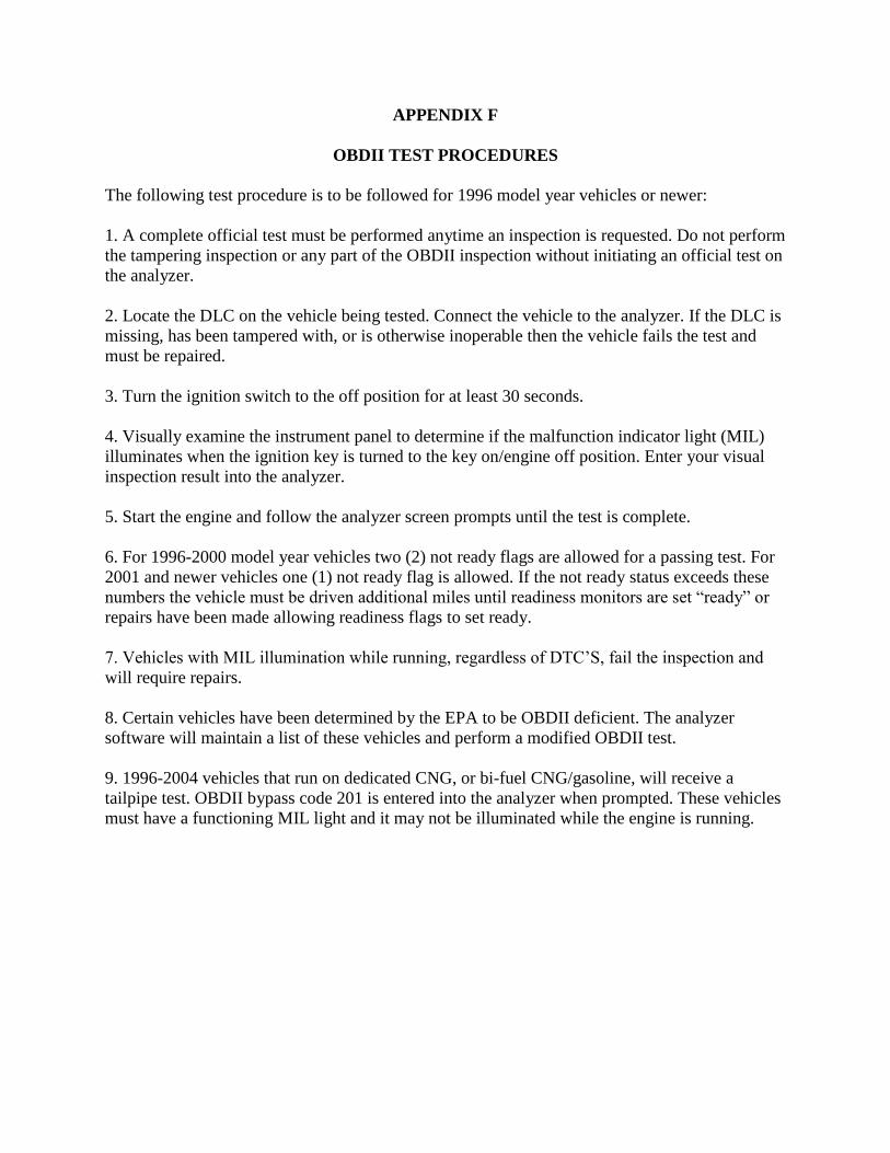
APPENDIX F
OBDII TEST PROCEDURES
The following test procedure is to be followed for 1996 model year vehicles or newer:
1. A complete official test must be performed anytime an inspection is requested. Do not perform
the tampering inspection or any part of the OBDII inspection without initiating an official test on
the analyzer.
2. Locate the DLC on the vehicle being tested. Connect the vehicle to the analyzer. If the DLC is
missing, has been tampered with, or is otherwise inoperable then the vehicle fails the test and
must be repaired.
3. Turn the ignition switch to the off position for at least 30 seconds.
4. Visually examine the instrument panel to determine if the malfunction indicator light (MIL)
illuminates when the ignition key is turned to the key on/engine off position. Enter your visual
inspection result into the analyzer.
5. Start the engine and follow the analyzer screen prompts until the test is complete.
6. For 1996-2000 model year vehicles two (2) not ready flags are allowed for a passing test. For
2001 and newer vehicles one (1) not ready flag is allowed. If the not ready status exceeds these
numbers the vehicle must be driven additional miles until readiness monitors are set “ready” or
repairs have been made allowing readiness flags to set ready.
7. Vehicles with MIL illumination while running, regardless of DTC’S, fail the inspection and
will require repairs.
8. Certain vehicles have been determined by the EPA to be OBDII deficient. The analyzer
software will maintain a list of these vehicles and perform a modified OBDII test.
9. 1996-2004 vehicles that run on dedicated CNG, or bi-fuel CNG/gasoline, will receive a
tailpipe test. OBDII bypass code 201 is entered into the analyzer when prompted. These vehicles
must have a functioning MIL light and it may not be illuminated while the engine is running.

Section X Part D
Appendix 2


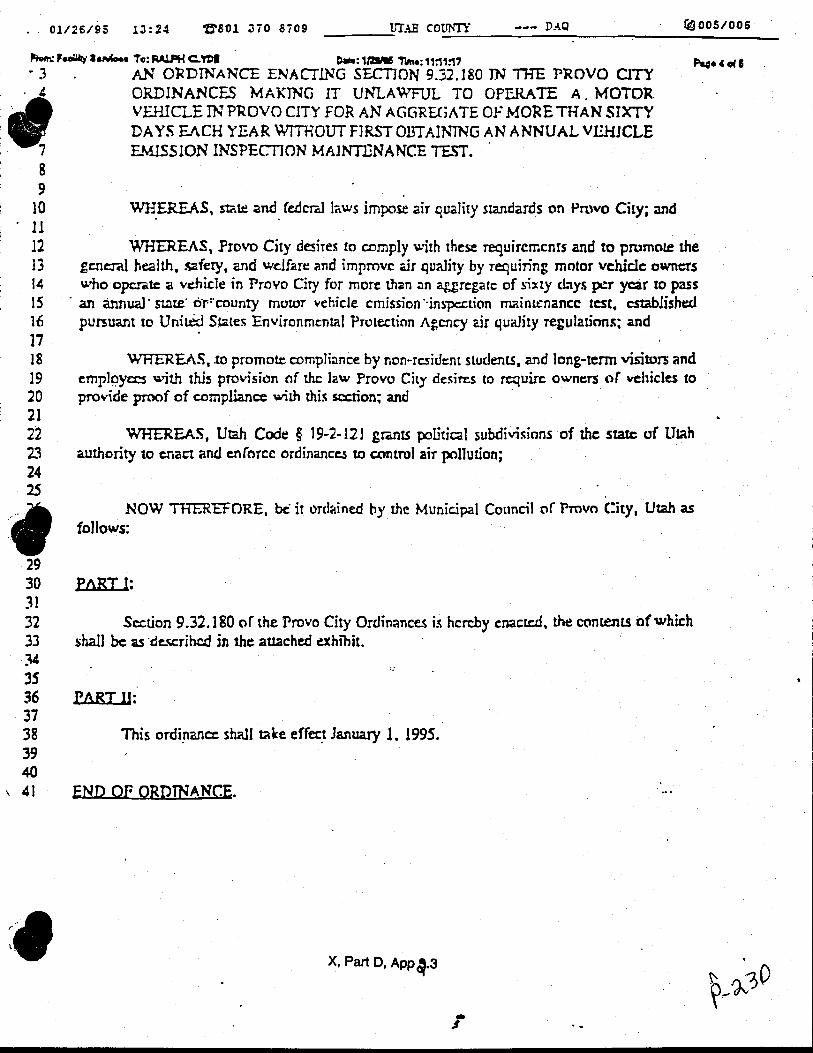
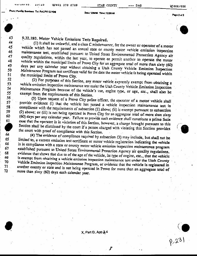

Section X
Part D
Appendix 3

Station Audits: I/M Program Stations are to be audited on a regular basis. (Not less than every other month). Audit frequency should be altered to a degree to help prevent the predictability of the audit date by station personnel. Station audits may be more frequent than every other month for high volume stations or stations that display possible problem areas regarding compliance with Department Rules and Regulations. If the analyzer is warmed up, a sample system leak check (including dual probe adapters) and a gas audit shall be performed by the station compliance officer using Department span gas. A copy of the gas audit shall be included with the I/M Station Audit Report. If the analyzer fails the sample system leak check and is not capable of being repaired while the audit is being conducted, the analyzer shall be locked out of TSI testing and allowed to perform OBDII only testing for a period of time not exceeding two weeks. A follow up audit shall be performed within a reasonable time after the station owner notifies our office that sample system repairs have been completed. If the analyzer fails the gas audit, this is to be noted on the I/M Station Audit Report. The analyzer will be automatically locked out of operation until a successful gas calibration is performed. An I/M Station Audit Report is to be filled out during each audit or follow-up audit. Follow up audits are to be clearly marked as to the type of audit they are and which item(s) required a follow up visit. All items listed on the report are to be checked each audit. Violations and obvious problem areas shall be noted on the report and brought to the attention of the station owner or responsible individual. Station personnel are required to sign reports. A copy of the report is provided to the station and a copy is submitted to the Program Manager for review. Violations that have not been corrected after a second warning, or by a defined date, shall result in an equipment lockout until violations have been corrected. Where possible, the compliance officer should attempt to observe an actual emissions test during the station audit. (this test may be used for annual mechanic recertification) Also, vehicles that have already been tested or are waiting to be tested may be checked for tampering violations. Data analysis using the Oracle program and/or the online VID should be included in station audits. The compliance officer should review test records before, during or after each station audit to identify possible procedural errors, anomalies or violations of Department Rules and Regulations.