utah transit authority streetcar design criteria · utah transit authority streetcar design...
TRANSCRIPT

Design Criteria UTA Streetcar
Rev No.
Prepared By
Approved By
Approval Date
Document Date
0 T. Jones CCC Feb. 2012 Feb. 2012
Utah Transit Authority Streetcar
Design Criteria
Chapter 1 General Requirements
February 2012

Utah Transit Authority
UTA Streetcar Design Criteria 1-i February 2012 Chapter 1
Table of Contents
CHAPTER 1 GENERAL REQUIREMENTS ................................................................................ 1
1.1 Purpose ............................................................................................................................................ 1 1.2 Project Goals ................................................................................................................................... 1
1.2.1 Proven Hardware ................................................................................................................ 1 1.2.2 Design Life ......................................................................................................................... 1 1.2.3 Service Integration .............................................................................................................. 1 1.2.4 Design to Cost ..................................................................................................................... 2 1.2.5 System Safety ..................................................................................................................... 2 1.2.6 Baseline Streetcar System ................................................................................................... 2
1.3 System Description .......................................................................................................................... 2 1.3.1 Stations ............................................................................................................................... 3 1.3.2 Track ................................................................................................................................... 3 1.3.3 Speed ................................................................................................................................... 3 1.3.4 Structures ............................................................................................................................ 3 1.3.5 Vehicles .............................................................................................................................. 3 1.3.6 Yard and Shop .................................................................................................................... 3 1.3.7 Overhead Contact System (OCS) ....................................................................................... 3 1.3.8 Signal/Traction Power ........................................................................................................ 3 1.3.9 Weather Conditions Criteria for Systems Design ............................................................... 3
1.4 Design Criteria Table of Contents ................................................................................................... 4 1.4.1 Specific Chapters ................................................................................................................ 4

Utah Transit Authority
UTA Streetcar Design Criteria 1-1 February 2012 Chapter 1
CHAPTER 1 GENERAL REQUIREMENTS
1.1 Purpose The material contained in the following chapters provides a uniform basis for project design of streetcar rail transit systems. These criteria serve as guidelines and do not substitute for engineering judgment and sound engineering practice. Exceptions may apply in special cases. Applications for exceptions to the criteria, deviation from the criteria, changes to the criteria, additions to the criteria, and other questions should be submitted in writing to UTA and must be approved in writing before the modification is implemented.
1.2 Project Goals The basic goal of the project is to provide an improved public transportation system in a cost-effective, environmentally sensitive and socially responsible manner. Design of project elements will be based on a “design to cost” philosophy as described in section 1.2.4.
1.2.1 Proven Hardware The streetcar system shall be designed to use proven subsystems hardware and design concepts. All of the major subsystems, such as vehicles, signaling, track and special trackwork, and traction power equipment shall be supplied by established manufacturers, have a documented operating history of previous and current usage, and be available off the shelf, so far as practicable. The same requirements shall apply to spare parts. Waiver of these requirements shall be considered only where the alternative subsystem offers substantial technical and cost advantages, is in an advanced stage of development, and has accumulated substantial test data under near-revenue conditions. Specifications for the streetcar system shall be prepared in such a way as to encourage competitive bidding by established manufacturers of transportation equipment in accordance with current federal procurement guidelines.
1.2.2 Design Life The streetcar system’s fixed facilities (tangent track, OCS system, structures and buildings) shall be designed for continued operation over a minimum period of 50 years before complete refurbishment and renovations are necessary due to wear. Major system equipment shall also be designed for a minimum of 30 years before complete replacement becomes necessary, assuming that approved maintenance policies are followed.
1.2.3 Service Integration The streetcar system shall be designed as an integral part of the overall UTA transportation system. Design considerations shall be made for the efficient interchange of passengers to and from private and other public transportation modes.

Utah Transit Authority
UTA Streetcar Design Criteria 1-2 February 2012 Chapter 1
1.2.4 Design to Cost This project uses the philosophy of budget-limited design. Each major element of the system shall be designed not to exceed the construction budgets established for the project. All systems identified in this document shall meet the criteria established herein and not exceed the project capital costs with appropriate escalation to year and month of construction.
1.2.5 System Safety Safety shall be the overriding policy in all aspects of system design and operations. All streetcar vehicles, equipment, and facilities shall be designed in accordance with all relevant codes and standards and maintained to ensure safe operation. All employees will take every reasonable precaution to avoid injury to themselves and others. Safety to the system’s operators, patrons, and the general public shall be implemented by:
• Appropriate design of streetcar vehicles (braking rates, use of fire retardant materials, etc.)
• Appropriate design of the wayside facilities (lighting of platforms, signals, etc.)
• Defining and adopting a System Safety Plan The items listed above are incorporated in the technical sections of this Design Criteria Manual. They will also be included in the detailed specifications that will be prepared for the construction and procurement of physical systems. The primary safety goal of the streetcar system is to achieve the highest practical level of safety while maintaining operational and cost effectiveness.
1.2.6 Baseline Streetcar System
• Single car operations with appropriate headways.
• Embedded/paved track in a mixed flow situation in an existing street
• Ballasted track (for sections of the streetcar system in an exclusive right-of-way) with concrete tie, continuously welded 115 RE rail, on top of existing sub-grade.
• Standard H-beam OCS poles in an exclusive right-of-way, and standard galvanized round poles on stations and on 90 degree turns. At locations along streets, urban design criteria shall be factored into the selection of industry standard “off-the-shelf” poles and other OCS components.
• Side loading, basic urban streetcar station platform.
• Existing utilities protected in place where facility is not in conflict.
• At-grade streetcar system resulting in safe, yet cost-effective system.
• Streetcar route minimizing right-of-way and environmental impacts.
• To the extent practicable, minimized roadway reconstruction.
1.3 System Description The design criteria in the following chapters apply to all UTA streetcar rail projects. All system elements will be designed to meet the requirements of the Americans with Disabilities Act (ADA).

Utah Transit Authority
UTA Streetcar Design Criteria 1-3 February 2012 Chapter 1
1.3.1 Stations Stations shall be either low-center or low-side loading platforms. ADA requirements will be met through the use of ramps or via level boarding.
1.3.2 Track The designs shall use 115 RE rail, minimum.
1.3.3 Speed The track alignment civil design speed in exclusive right-of-way shall be 35 mph where the right-of-way and physical constraints permit. Superelevation shall be designed to match the anticipated streetcar running speed of each section of track. In the street-running sections, the design speed will match the posted street traffic speed, where practical, except as directed in MUTCD.
1.3.4 Structures Existing bridges and culverts shall be retrofitted or repaired as necessary to carry the streetcar loads and to meet seismic requirements.
1.3.5 Vehicles The streetcar vehicle shall use a nominal 750 Vdc and be of proven technology. Vehicles may be new or used depending on the cost and timing of the procurement. All vehicles shall be “low-floor” types to obviate the need for mini high-block platforms.
1.3.6 Yard and Shop The yard and shop shall provide standard maintenance and operations services for the streetcar vehicle fleet.
1.3.7 Overhead Contact System (OCS) In street running sections of the streetcar route, urban design criteria shall be considered in the design of the OCS system.
1.3.8 Signal/Traction Power Signaling shall be accomplished through the use of existing traffic control devices where possible. The traction power shall be supplied by 1.5-megawatt substations located at approximately 1-mile intervals. Coordinate the location and size of signal/traction power equipment with UTA.
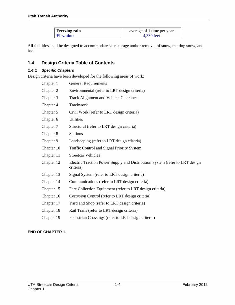
1.3.9 Weather Conditions Criteria for Systems Design Systems equipment including vehicles, electric traction supply and distribution system, signal system, and fare collection equipment shall be capable of maintaining operation within the climatic conditions of the Salt Lake City area. The following data are to be used as the design weather conditions:
Temperature Range −30° to +110° F Relative humidity 8 to 100% Maximum rainfall in 24 hours 6.7 inches Maximum snowfall in 24 hours 18.4 inches Maximum wind speed 71 mph
Utah Transit Authority
UTA Streetcar Design Criteria 1-4 February 2012 Chapter 1
Freezing rain average of 1 time per year Elevation 4,330 feet
All facilities shall be designed to accommodate safe storage and/or removal of snow, melting snow, and ice.
1.4 Design Criteria Table of Contents 1.4.1 Specific Chapters Design criteria have been developed for the following areas of work:
Chapter 1 General Requirements
Chapter 2 Environmental (refer to LRT design criteria)
Chapter 3 Track Alignment and Vehicle Clearance
Chapter 4 Trackwork
Chapter 5 Civil Work (refer to LRT design criteria)
Chapter 6 Utilities
Chapter 7 Structural (refer to LRT design criteria)
Chapter 8 Stations
Chapter 9 Landscaping (refer to LRT design criteria)
Chapter 10 Traffic Control and Signal Priority System
Chapter 11 Streetcar Vehicles
Chapter 12 Electric Traction Power Supply and Distribution System (refer to LRT design criteria)
Chapter 13 Signal System (refer to LRT design criteria)
Chapter 14 Communications (refer to LRT design criteria)
Chapter 15 Fare Collection Equipment (refer to LRT design criteria)
Chapter 16 Corrosion Control (refer to LRT design criteria)
Chapter 17 Yard and Shop (refer to LRT design criteria)
Chapter 18 Rail Trails (refer to LRT design criteria)
Chapter 19 Pedestrian Crossings (refer to LRT design criteria) END OF CHAPTER 1.

Design Criteria UTA Streetcar
Rev No.
Prepared By
Approved By
Approval Date
Document Date
0 T. Jones CCC Feb. 2012 Feb. 2012
Utah Transit Authority Streetcar
Design Criteria
Chapter 2 Environmental
February 2012
Utah Transit Authority
UTA Streetcar Design Criteria 2-1 February 2012 Chapter 2
CHAPTER 2 ENVIRONMENTAL CRITERIA
For the guidance and criteria for implementing environmental features into UTA streetcar projects, and for the criteria by which to avoid, minimize, and/or mitigate environmental impacts, refer to the latest version of Chapter 2 of the UTA Light Rail Transit Design Criteria. END OF CHAPTER 2.

Design Criteria UTA Streetcar
Rev No. Prepared By Approved By Approval Date Document Date
0 T. Jones CCC February 2012 February 2012
Utah Transit Authority Streetcar
Design Criteria
Chapter 3 Track Alignment & Vehicle Clearance
February 2012

Utah Transit Authority
UTA Streetcar Design Criteria 3-i February 2012 Chapter 3
Table of Contents
CHAPTER 3 TRACK ALIGNMENT AND VEHICLE CLEARANCE ...................................... 1
3.1 General ............................................................................................................................................ 1 3.2 Nomenclature and Definitions ......................................................................................................... 1
3.2.1 Horizontal Alignment ......................................................................................................... 1 3.2.2 Vertical Alignment ............................................................................................................. 1
3.3 Streetcar Track Alignment Criteria ................................................................................................. 2 3.3.1 Horizontal Alignment ......................................................................................................... 2
3.3.1.1 Tangents ..................................................................................................... 2 3.3.1.2 Circular Curves ..................................................................................................... 2 3.3.1.3 Spiral Transitions ................................................................................................... 3 3.3.1.4 Superelevation ..................................................................................................... 4
3.3.2 Vertical Alignment ............................................................................................................. 5 3.3.2.1 Tangents ..................................................................................................... 5 3.3.2.2 Grades ..................................................................................................... 5 3.3.2.3 Vertical Curves ..................................................................................................... 6 3.3.2.4 Vertical Curve Lengths .......................................................................................... 6
3.4 Clearances ....................................................................................................................................... 7 3.4.1 Vehicle Description ............................................................................................................ 7
3.4.1.1 Static Outline ..................................................................................................... 7 3.4.1.2 Dynamic Outline .................................................................................................... 7
3.4.2 Track Curvature and Superelevation Adjustment ............................................................... 7 3.4.2.1 Vehicle Middle Ordinate Shift and End Overhang .............................................. 10 3.4.2.2 Vehicle Shifts Due to Superelevation .................................................................. 10 3.4.2.3 Turnouts ................................................................................................... 11
3.4.3 Horizontal Clearances ....................................................................................................... 11 3.4.3.1 Track Spacing for Exclusive Track ...................................................................... 11 3.4.3.2 Clearance to Obstructions .................................................................................... 11 3.4.3.3 Running Clearances ............................................................................................. 11 3.4.3.4 Construction Tolerances along Proposed Structures ........................................... 11 3.4.3.5 Track Construction and Maintenance Tolerances ................................................ 12 3.4.3.6 Exceptions to Design Envelope Clearances ......................................................... 12 3.4.3.7 Retaining Walls ................................................................................................... 12 3.4.3.8 Safety Clearances ................................................................................................. 13
3.4.4 Vertical Clearances ........................................................................................................... 14

Utah Transit Authority
UTA Streetcar Design Criteria 3-1 February 2012 Chapter 3
CHAPTER 3 TRACK ALIGNMENT AND VEHICLE CLEARANCE
3.1 General The criteria for the alignment of streetcar rail transit, as set forth in this chapter, have been established to provide:
• Optimum safety
• Passenger comfort
• Ease of maintenance The criteria in this Chapter are supplemented by the track work design criteria in Chapter 4.
3.2 Nomenclature and Definitions 3.2.1 Horizontal Alignment
DA = degree of curvature, arc definition
Ea = actual superelevation (inches)
Eu = unbalanced superelevation (inches)
Eq = Ea + Eu = equilibrium superelevation (inches)
Lc = length of circular curve (feet)
Ls = length of spiral (feet)
R = radius of curve (feet)
T = tangent length (feet)
V = design speed (mph)
3.2.2 Vertical Alignment
Rv = minimum radius of curvature of the vertical curve (feet)
Lvc = length of vertical curve (feet)
G1 = percent grade of approaching tangent
G2 = percent grade of departing tangent
T = length of uniform grade tangent (feet)
G1 − G2 = algebraic difference in gradients connected by the vertical curve (percent)
V = design speed (mph)
Utah Transit Authority
UTA Streetcar Design Criteria 3-2 February 2012 Chapter 3
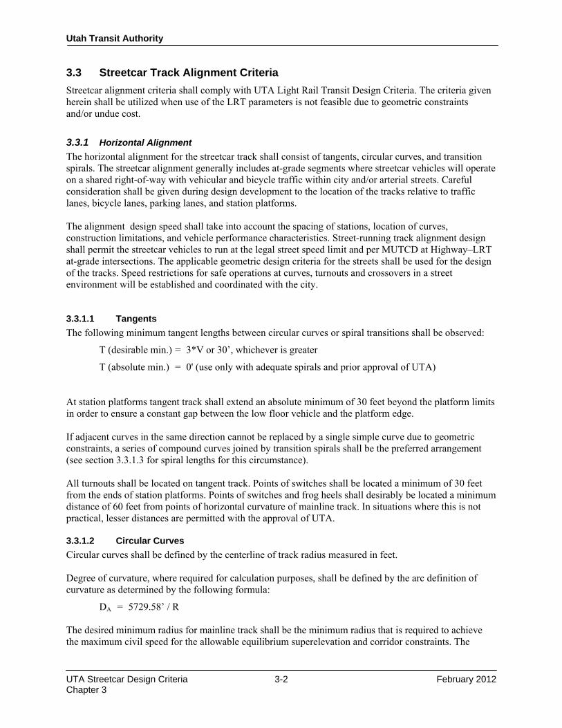
3.3 Streetcar Track Alignment Criteria Streetcar alignment criteria shall comply with UTA Light Rail Transit Design Criteria. The criteria given herein shall be utilized when use of the LRT parameters is not feasible due to geometric constraints and/or undue cost.
3.3.1 Horizontal Alignment The horizontal alignment for the streetcar track shall consist of tangents, circular curves, and transition spirals. The streetcar alignment generally includes at-grade segments where streetcar vehicles will operate on a shared right-of-way with vehicular and bicycle traffic within city and/or arterial streets. Careful consideration shall be given during design development to the location of the tracks relative to traffic lanes, bicycle lanes, parking lanes, and station platforms. The alignment design speed shall take into account the spacing of stations, location of curves, construction limitations, and vehicle performance characteristics. Street-running track alignment design shall permit the streetcar vehicles to run at the legal street speed limit and per MUTCD at Highway–LRT at-grade intersections. The applicable geometric design criteria for the streets shall be used for the design of the tracks. Speed restrictions for safe operations at curves, turnouts and crossovers in a street environment will be established and coordinated with the city. 3.3.1.1 Tangents The following minimum tangent lengths between circular curves or spiral transitions shall be observed:
T (desirable min.) = 3*V or 30’, whichever is greater
T (absolute min.) = 0' (use only with adequate spirals and prior approval of UTA) At station platforms tangent track shall extend an absolute minimum of 30 feet beyond the platform limits in order to ensure a constant gap between the low floor vehicle and the platform edge. If adjacent curves in the same direction cannot be replaced by a single simple curve due to geometric constraints, a series of compound curves joined by transition spirals shall be the preferred arrangement (see section 3.3.1.3 for spiral lengths for this circumstance). All turnouts shall be located on tangent track. Points of switches shall be located a minimum of 30 feet from the ends of station platforms. Points of switches and frog heels shall desirably be located a minimum distance of 60 feet from points of horizontal curvature of mainline track. In situations where this is not practical, lesser distances are permitted with the approval of UTA. 3.3.1.2 Circular Curves Circular curves shall be defined by the centerline of track radius measured in feet. Degree of curvature, where required for calculation purposes, shall be defined by the arc definition of curvature as determined by the following formula:
DA = 5729.58’ / R The desired minimum radius for mainline track shall be the minimum radius that is required to achieve the maximum civil speed for the allowable equilibrium superelevation and corridor constraints. The

Utah Transit Authority
UTA Streetcar Design Criteria 3-3 February 2012 Chapter 3
corresponding superelevation for a given curve shall result in lateral acceleration less than or equal to 0.10g. The absolute minimum radius is 82 feet unless otherwise approved and verified by the vehicle manufacturer and UTA. The length of the circular curve, not including connecting spirals, shall be as follows:
Minimum LC = 1.5*V, where V = design speed, mph (one second of travel time at design speed)
In locations with geometric constraints and with prior UTA approval, the length of the circular curve added to the sum of one-half the length of both spirals is an acceptable method of determining compliance with the above criteria. 3.3.1.3 Spiral Transitions Spiral transitions shall be used at all mainline curves of radii of less than 10,000 feet (where possible) to provide a smooth transition between the tangent track and circular curve track. This transition is required to eliminate the abrupt change in direction of the vehicle wheel path from tangent track to curved track, to provide a smooth transition for the rate of change of applied superelevation, and to provide a comfortable transition for the rate of change of lateral acceleration. Transition spirals shall be true clothoid spirals where the instantaneous radius varies directly with the distance from the point of tangency. Examples include the Barnett Spiral, the Hickerson Spiral, and other similar mathematically defined curves as published in standard route geometry reference books and used in commercial coordinate geometry computer programs. The length of spiral transitions shall be as defined in this section, unless otherwise prohibited by street section or operations constraints. In such cases, the speed limit of the curve shall be restricted to meet the established criteria based on the available spiral transition lengths. The minimum length of transition spiral shall be the largest length as determined by the following formulas:
(1) LS = 31*Ea (track twist not to exceed 1” in 31’)
(2) LS = 1.10*Ea*V (superelevation runoff/vehicle roll limited to 1.33” per sec.)
(3) LS = 0.82*Eu*V (0.1g max. lateral acceleration, jerk rate limited to 0.04 g/sec and Eu max. of 4.5”)
(4) LS = 31 feet (absolute minimum)
where,
LS = minimum length of transition spiral, feet
Ea = actual superelevation, inches
V = design speed, mph
Eu = unbalanced superelevation, inches
Twist = rate of change of cross level of track due to applied superelevation
Jerk rate = rate of change of lateral acceleration

Utah Transit Authority
UTA Streetcar Design Criteria 3-4 February 2012 Chapter 3
For geometrically constrained embedded track locations, and with prior approval of UTA, the formulas above may be substituted with those found in the latest version of AREMA Chapter 12 Part 8. Where compound curves are used, the minimum length of connecting transition spiral shall be the largest length as determined by the following formulas:
(1) LS = 31*(Ea2 − Ea1)
(2) LS = 1.10*(Ea1 − Ea2 )*V
(3) LS = 0.82*(Eu1 − Eu2 )*V
(4) LS = 31 feet (absolute minimum)
where,
LS = minimum length of compounding spiral, feet
a1 = actual superelevation of first curve, inches
Ea2 = actual superelevation of second curve, inches
Eu1 = unbalanced superelevation of first curve, inches
Eu2 = unbalanced superelevation of second curve, inches
V = design speed, mph Spiral transitions are not required in special track work. 3.3.1.4 Superelevation For street-running track, superelevation/cross slope must be designed to accommodate the existing street sections and cross traffic and to assure positive drainage toward storm water inlets. When street sections are not an issue, the criteria in this section shall govern. The design speed of a given curve shall be limited to the maximum allowable speed as determined by the following formula based on a standard track gauge of 4 feet 8½ inches:
Eq = Ea + Eu = 3.96 V2 R
where,
Eq = equilibrium superelevation
Ea = actual superelevation, inches
Eu = unbalanced superelevation, inches
V = design speed, mph
R = curve radius, feet The equilibrium superelevation is the sum of the actual superelevation (Ea) and the unbalanced superelevation (Eu). When superelevation is applied it shall be in accordance with the following requirements:
• Ea shall have a minimum value of ½ inch and a maximum value of 6 inches. When the calculated required Ea is less than ½ inch, 0 shall be used.
• Ea shall be specified in ¼-inch increments. When the calculated requirement is not a whole-number multiple of ¼-inch, the next higher whole-number multiple of ¼-inch shall be used.

Utah Transit Authority
UTA Streetcar Design Criteria 3-5 February 2012 Chapter 3
The unbalanced superelevation (Eu) shall not be greater than plus 4.5 inches. When the following maximum values of Ea or Eu would be exceeded in order to reach the desired design speed, the following maximum values should be used and a limit shall be placed on the design speed of a curve:
Ea (direct fixation track, embedded track in an exclusive lane) = 6 inches
Ea (embedded track in a shared lane) = 3 inches
Ea (ballasted track) = 4 inches
Eu (lateral acceleration < 0.10g) = 4.5 inches Because of the cross slope of the street, in a mixed traffic situation it is possible that Ea will be a negative number. In this instance, any negative Ea needs to be added to the value of Eu and that sum used to determine the requisite spiral length. At special track work, the actual superelevation (Ea) shall be 0 until the unbalanced superelevation reaches 3 inches. At this point, a limit shall be placed on the design speed through the turnout. The top of inside rail in a curve shall be set to the design profile grade and the required superelevation shall be applied to the outside rail.
3.3.2 Vertical Alignment 3.3.2.1 Tangents The minimum length of constant tangent grade shall be:
T (desirable minimum) = 3 V
T (absolute minimum) = 40 feet At stations, the tangent grade shall extend a desirable minimum distance of 30 feet beyond each end of platform. A distance less than 45 feet may be used with prior UTA approval. All special track work shall be located on tangent grade and the associated points of switches/frog heels shall be located a desirable minimum distance of 60 feet from the point of vertical curvature or grade change. The absolute minimum distance depends on the clearances required for the specific turnout geometry and rail joint locations. Street-running track must meet the profile of the existing street and no minimum tangent length between curves shall be required. However, verification must be made that the vertical geometry will not impede the streetcar vehicle performance. 3.3.2.2 Grades
• Mainline Grade:
Desired maximum grade (1,500 feet or greater) 4%
Maximum short sustained grade (less than 1,500 feet) 6%
Absolute maximum grade – ballasted track 6%
Desirable maximum grade – embedded and direct fixation track 6%

Utah Transit Authority
UTA Streetcar Design Criteria 3-6 February 2012 Chapter 3
Absolute maximum grade – embedded and direct fixation track (subject to UTA approval) 8%
• Embedded Track Grade:
Min. = 0.5%
• Station Area Grade:
Desirable max. grade = 0.5%
max. grade = 1.5%*
* any grades exceeding 1.5% requires prior UTA approval 3.3.2.3 Vertical Curves All vertical curves shall be defined by a parabolic curve having a constant rate of grade change as expressed by the formula:
M.O. = (G1 – G2)*L 800
where,
M.O. = middle ordinate distance from PVI to curve, feet
G1 − G2 = algebraic difference in grades, expressed in %
L = length of vertical curve, feet Vertical curves shall be provided at all tangent grade intersections where:
(G1 − G2) > 0.50%
where,
G1 − G2 = algebraic difference in grades, expressed in % 3.3.2.4 Vertical Curve Lengths The required length of vertical curve shall be the largest length as calculated from the following formula, rounded off to the nearest 1 foot:
L (desirable) = 200 (G1 − G2)
L (preferred minimum) = 100 (G1 − G2)
L (absolute min. crest curve) = (G1 − G2)V2 25
L (absolute min. sag curve) = (G1 − G2)V2 45
where,
L = minimum length of vertical curve, feet
G1 − G2 = algebraic difference in grades, expressed in %
V = design speed, mph The minimum equivalent radius of vertical curvature on mainline tangent track should not be less than 820 feet for crests and 1150 feet for sags. This equivalent radius of curvature can be calculated from the following formula:

Utah Transit Authority
UTA Streetcar Design Criteria 3-7 February 2012 Chapter 3
Rv = L/(0.01(G1 – G2)) Where: Rv = min. radius of curvature of a vertical curve in feet Vertical broken back curves and short horizontal curves at sags and crests should be avoided. The minimum requirements in this section are the preferred standards; however, existing conditions may require exemptions on a case-by-case basis. Vertical curve lengths and radii of vertical curvature less than absolute minimum require approval from UTA.
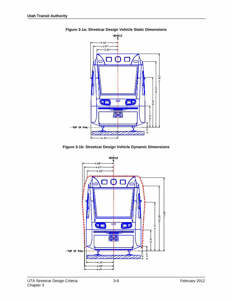
3.4 Clearances 3.4.1 Vehicle Description To allow the design of fixed facilities to proceed prior to the selection of a specific streetcar vehicle, a design vehicle has been established. This design vehicle is based upon the Siemens ultra short S70 low floor light rail vehicle (81.37 feet long). 3.4.1.1 Static Outline The static dimensions of the design vehicle are shown in Figure 3-1a. 3.4.1.2 Dynamic Outline The dynamic outline of the streetcar vehicle includes the anticipated dynamic movement of the vehicle during operation and factors to account for wear of both vehicle and track components during the life of the system. Dynamic outline dimensions are shown in Figure 3-1b. The major factors which affect the dynamic outline consist of the following:
• Lateral roll of the vehicle
• Primary and secondary suspension failure
• Vehicle body yaw
• Lateral play in the wheels
• Rail wear and wheel flange wear
• Vehicle manufacturer’s tolerances The actual extents to which these factors affect the total dynamic envelope are based on the specific vehicle selected. The static outline and assumed dynamic clearance of the design vehicle shown in Figures 3-1a and 3-1b shall be used during preliminary design as a basis for determining vehicle clearances to fixed facilities. Upon final selection of a streetcar vehicle, the designer shall verify vehicle clearances using actual dimensions of the vehicle that are obtained from the streetcar manufacturer.
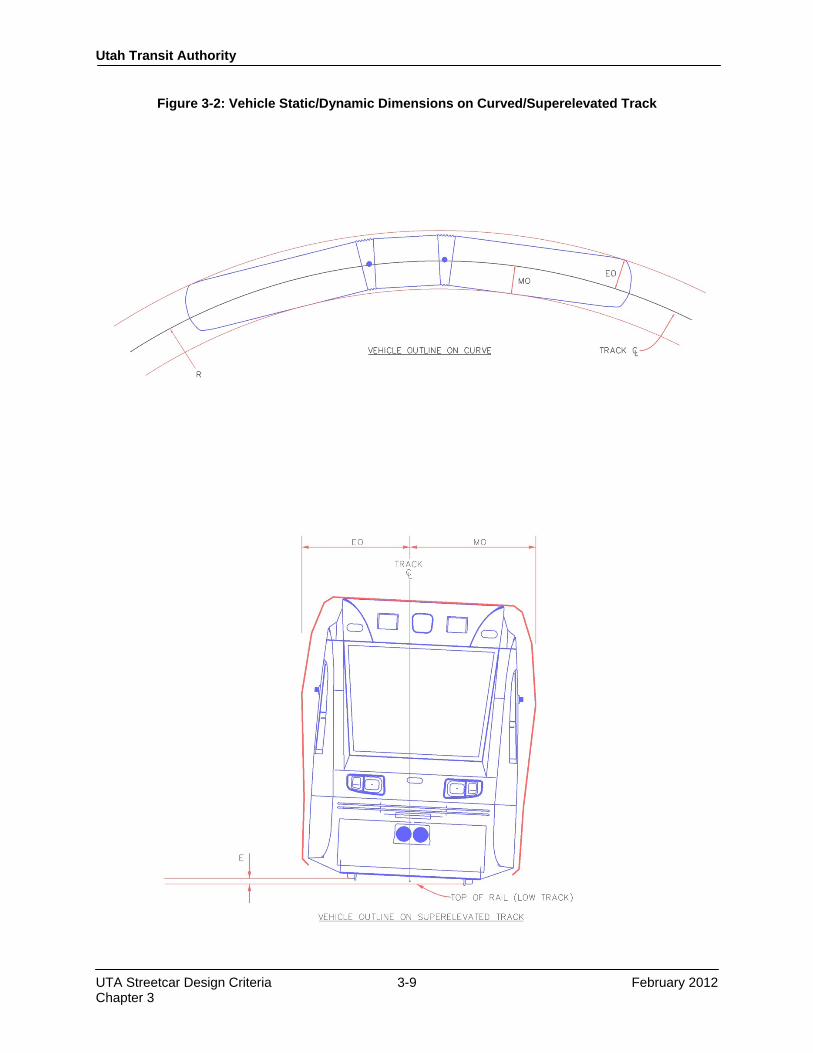
3.4.2 Track Curvature and Superelevation Adjustment When a rail vehicle enters a horizontal curve—including turnouts—the dynamic outline must be adjusted for overhang at the end of the vehicle and for middle ordinate shift (belly-in) midway between the trucks (bogies) of the vehicles. The presence of superelevation shall increase the middle ordinate shift particularly toward the top of the vehicle. See Figure 3-2.
Utah Transit Authority
UTA Streetcar Design Criteria 3-8 February 2012 Chapter 3
Figure 3-1a: Streetcar Design Vehicle Static Dimensions
Figure 3-1b: Streetcar Design Vehicle Dynamic Dimensions
Utah Transit Authority
UTA Streetcar Design Criteria 3-9 February 2012 Chapter 3
Figure 3-2: Vehicle Static/Dynamic Dimensions on Curved/Superelevated Track

Utah Transit Authority
UTA Streetcar Design Criteria 3-10 February 2012 Chapter 3
3.4.2.1 Vehicle Middle Ordinate Shift and End Overhang Values for the design vehicle middle ordinate shift toward the curve center, and the design vehicle end overhang away from the curve center are tabulated in Table 3-1. These values shall be used during preliminary design as a basis for determining vehicle clearances to fixed facilities. For values of radii that lie between that which is shown in the table, interpolation shall be utilized to calculate the middle ordinate and end overhang. Upon final selection of a streetcar vehicle, the designer shall verify vehicle clearances using actual dimensions of the vehicle that are obtained from the streetcar manufacturer.
Table 3-1 Design Vehicle Middle Ordinate Shift & End Overhang
Centerline Track Radius (ft)
Mid‐Ordinate (ft)
End Overhang (ft)
82 5.05 5.56 100 4.93 5.32 150 4.74 4.96 200 4.65 4.78 250 4.59 4.70 300 4.56 4.64 350 4.53 4.61 400 4.51 4.58 450 4.49 4.55 500 4.49 4.54 600 4.46 4.51 700 4.45 4.49 800 4.44 4.48 900 4.43 4.46 1000 4.43 4.45 2000 4.40 4.41 3000 4.39 4.40 4000 4.39 4.39 5000 4.38 4.39 10000 4.38 4.38
3.4.2.2 Vehicle Shifts Due to Superelevation The distance from the centerline of track to the middle ordinate of the vehicle shall be increased where superelevation is applied in a curve. The maximum shift toward the curve centerline based on a desired distance H feet above the top of rail can be calculated by the formula:
X = 0.016 E H
where,
X = lateral shift due to superelevation, inches
E = actual superelevation, inches
H = height of point of analysis on vehicle

Utah Transit Authority
UTA Streetcar Design Criteria 3-11 February 2012 Chapter 3
Figure 3-2 indicates how these dimensions relate to the CLRV. 3.4.2.3 Turnouts When a streetcar vehicle travels through the diverging route of a turnout the dynamic outline will be affected. During final design, the dynamic outline shall be checked adjacent to, and 45 feet beyond, all curved components (switches, closure rails) of the diverging turnout route in order to determine potential conflicts with adjacent structures, poles, etc.
3.4.3 Horizontal Clearances For exclusive track, all existing and proposed structures, including catenary poles, bridge pier columns, and retaining walls shall clear the total design vehicle dynamic outline by a distance equal to or greater than the sum of applicable clearances and tolerances defined in this section. Clearances shall be checked between the design vehicle dynamic outline and all adjacent structures along tangent track and at turnouts a minimum of 50 feet in either direction of the structures. This is to verify that an adjacent curved track does not affect the clearance in the adjoining tangent section. For in-street track with a shared lane, the designer should use the static envelope of the vehicle plus six inches to establish traffic striping and lane lines. The desired minimum lane width is 12 feet with an absolute minimum of 11 feet. In order to minimize automobiles driving directly on the rails, the track shall be offset in the shared automobile lane where feasible to keep the rails out of the wheel path of cars driving in the center of the lane. Clearances to all rigid objects and passing streetcar vehicles shall comply with all requirements described for the exclusive track. 3.4.3.1 Track Spacing for Exclusive Track The minimum centerline to centerline distance between two tracks shall be 13 feet where there are center poles. Additional distance may be required when the tracks are curved or superelevated. 3.4.3.2 Clearance to Obstructions The distance between any fixed object along the trackway and the centerline of track shall be equal the design envelope:
design envelope = (dynamic outline) + (running clearance) + (construction and maintenance tolerances) Exceptions to the design envelope requirements are listed in Section 3.4.3.6. 3.4.3.3 Running Clearances The running clearance provides clear passage for a vehicle which has moved to the extreme position within the dynamic outline. Design running clearances for exclusive streetcar track shall be:
• 4″ for poles and structural supports
• 2″ for all other permanent structures 3.4.3.4 Construction Tolerances along Proposed Structures A construction tolerance is required when a new structure is constructed adjacent to or above the streetcar corridor. This tolerance is in addition to the construction and maintenance tolerance specified in section 3.4.3.5 which apply to the track. These values are for purposes of providing clearances only and are not a
Utah Transit Authority
UTA Streetcar Design Criteria 3-12 February 2012 Chapter 3
guidance for what construction tolerances are acceptable to UTA. In addition to structures built as part of the UTA project, they anticipate deviations from plan of any future structures built alongside of the track by others over whom UTA may have only limited control. These clearances shall be:
• 6″ for soldier pile and lagging walls
• 1″ for other proposed structures 3.4.3.5 Track Construction and Maintenance Tolerances Track construction and maintenance tolerances account for a combination of factors such as track misalignment, wheel and track gauge tolerances, and wheel and rail wear. These tolerances also include provision for any cross level variances between the track rails due to unintentional construction inaccuracies and possible deference of track maintenance during operation of the system. The following track construction and maintenance tolerances apply:
• Direct fixation or embedded track ½ inch
• Mainline tie and ballast track 3 inches
• Special track work ½ inch
• Yard track 3 inches These tolerances are theoretical worst case values and not actual acceptable construction tolerances. 3.4.3.6 Exceptions to Design Envelope Clearances All structures installed above the top of the nearest rail must be set either at or beyond the design envelope with the following exclusions:
• Retaining walls (see Section 3.4.3.7)
• Cut sections (see Section 3.4.3.7)
• Fill sections (see Section 3.4.3.7)
• Safety clearances (see Section 3.4.3.8) 3.4.3.7 Retaining Walls Retaining walls shall comply with the minimum clearance requirements outlined below. When a minimum clearance value is applied on one side of the track, a minimum shall not simultaneously be used on the other side of the track since a safe refuge area must be provided for passengers being evacuated from a train and for maintenance-of-way employees. Additional clearances must be provided for installation of wayside signals where used. The civil and structural designers shall coordinate with the designers of the train control system so as to provide space for wayside signal equipment, to provide space for maintenance employees to service signal equipment, and to assure that train operators have a clear line of sight to signal indications at appropriate distances from the signal. Cut Sections

Utah Transit Authority
UTA Streetcar Design Criteria 3-13 February 2012 Chapter 3
The minimum clearance from the centerline of tangent track to the nearest face of the wall shall be the largest of the following:
• The dynamic envelope clearance
• 7 feet 1 inch for streetcar exclusive track Fill Sections The top of a retaining wall below track grade shall be at the same elevation as the top of the rail nearest to the wall. The clearance distance from the centerline of tangent track to the near face of the retaining wall shall be an absolute minimum of 6 feet (8 feet 6 inches for joint use). 3.4.3.8 Safety Clearances Space shall be provided to allow for emergency evacuation of streetcar passengers and provide an area for maintenance personnel to safely stand during passage of trains. This space should be provided in areas of restricted right-of-way, in areas of retained cut, and on structures. The space should be reasonably level and nominally 30 inches in width. The space shall be located to fulfill the following requirements:
• 30 inches of width beyond the static vehicle envelope
• 18 to 24 inches of width beyond the vehicle dynamic envelope

Utah Transit Authority
UTA Streetcar Design Criteria 3-14 February 2012 Chapter 3
3.4.4 Vertical Clearances The following minimum vertical clearances are required from the top of the high rail to the underside of any overhead structure, within the horizontal limits of the design envelope:
Trackway Environment Minimum Height of Overhead Obstruction Exclusive streetcar track in dedicated rail corridor
18′-0″ plus the depth of the catenary system1, preferred 15′-0″ target minimum2 14′-3″ absolute minimum2, 3
Streetcar with mixed traffic in same lane or exclusive streetcar track being crossed by roadway at grade
18′-0″ plus the depth of the catenary system1, preferred minimum4 16′-0″ plus the depth of the catenary system1, absolute minimum4
Notes
1. Depth of catenary system can vary depending on support system used. Coordinate with OCS designers.
2. Requires special OCS structures and may not be suitable for higher speeds. Coordinate with OCS designers.
3. Vehicle pantograph may be close to its “lockdown” height. Coordinate with vehicle designers and UTA vehicle maintenance staff.
4. Per the National Electrical Safety Code, the trolley contact wire must not be less than 18′-0″ above the top of any roadway pavement under any condition of loading (including wind and ice loading) or temperature. Exceptions must be obtained from UTA for any clearance less than that minimum.
END OF CHAPTER 3.

Design Criteria UTA Streetcar
Rev No. Prepared By Approved By Approval Date Document Date 0 T. Jones CCC February 2012 February 2012
Utah Transit Authority Streetcar
Design Criteria
Chapter 4 Trackwork February 2012
Utah Transit Authority
UTA Streetcar Design Criteria 4-i February 2012 Chapter 4
Table of Contents
CHAPTER 4 TRACKWORK ............................................................................................................ 1
4.1 General ............................................................................................................................................ 1 4.2 Track System .................................................................................................................................... 1 4.3 Track Standards ............................................................................................................................... 2 4.4 Track Construction Types ................................................................................................................ 2
4.4.1 Ballasted Track ................................................................................................................... 2 4.4.2 Embedded Track ................................................................................................................. 2
4.4.2.1 Cross Slope ..................................................................................................... 3 4.4.3 Direct Fixation Track .......................................................................................................... 4
4.4.3.1 Rail Fastener .................................................................................................... 4 4.4.3.2 Concrete Plinth or Pad ..................................................................................... 5
4.5 Track Gauge .................................................................................................................................... 5 4.6 Wheel Profile and Gauge ................................................................................................................. 5 4.7 Track Construction Tolerances ........................................................................................................ 5 4.8 Traction Power—Impact on Track .................................................................................................. 6 4.9 Signaling and Train Control Impact on Track ................................................................................. 7 4.10 Ballast, Subballast, and Subgrade ................................................................................................... 7
4.10.1 Subgrade ............................................................................................................................. 7 4.10.2 Subballast ............................................................................................................................ 7 4.10.3 Ballast ................................................................................................................................. 7
4.11 Concrete Ties, Timber Crossties, and Timber Switch Ties .............................................................. 8 4.11.1 Timber Ties ......................................................................................................................... 8 4.11.2 Switch Ties ......................................................................................................................... 9
4.12 Running Rail .................................................................................................................................... 9 4.12.1 Standard Carbon Steel Rail ............................................................................................... 10 4.12.2 High Strength Rail ............................................................................................................ 10 4.12.3 Continuous Welded Rail ................................................................................................... 10
4.12.3.1 Rail Deflection .............................................................................................. 10 4.12.3.2 Maximum Bending Stress ............................................................................. 11 4.12.3.3 Axial Tensile and Compressive Forces ......................................................... 11 4.12.3.4 Rail Break Forces .......................................................................................... 11 4.12.3.5 Unbalanced Thermal Forces at Special Trackwork ....................................... 12
4.13 Use of Rails and Other Track Material from Existing Tracks ....................................................... 12 4.14 Restraining Rail and Strap Guard for Curved Track .................................................................... 12 4.15 Emergency Guardrail .................................................................................................................... 13 4.16 Tie Plates for Timber Ties .............................................................................................................. 13 4.17 Special Trackwork Plates for Timber Switch Ties ......................................................................... 13 4.18 Insulated Joint Bars ....................................................................................................................... 13
4.18.1 Continuous Welded Rail ................................................................................................... 14 4.18.2 Jointed Rail ....................................................................................................................... 14

Utah Transit Authority
UTA Streetcar Design Criteria 4-ii February 2012 Chapter 4
4.19 Bonded Joint Bars .......................................................................................................................... 14 4.20 Joint Bars ....................................................................................................................................... 14 4.21 Compromise Joint Bars.................................................................................................................. 14 4.22 Derails ........................................................................................................................................... 15 4.23 Special Trackwork ......................................................................................................................... 15 4.24 Switch Machines—Power Operated and Manual .......................................................................... 19 4.25 Rail Expansion Joints .................................................................................................................... 19 4.26 At-Grade Crossings ....................................................................................................................... 19 4.27 Miscellaneous Track Appurtenances ............................................................................................. 19
4.27.1 Buffer Stops ...................................................................................................................... 19 4.27.2 Embedded Track Drains ................................................................................................... 20 4.27.3 Rail Lubricators ................................................................................................................ 20

Utah Transit Authority
UTA Streetcar Design Criteria 4-1 February 2012 Chapter 4
CHAPTER 4 TRACKWORK
4.1 General The trackwork chapter provides details for the design and construction of the trackwork and its interface with other elements in UTA streetcar projects. Trackwork systems are composed of a number of elements, each of which has a definite interaction with other elements of the system. Because of this interaction, the design criteria for trackwork must be accomplished as a systems approach with a cause and effect analysis being undertaken on each of the elements. In performing this trackwork design, consideration of allied factors such as safety, stray current, noise, and vibration must be considered. In addition, the relationship of trackwork design to the design of other elements of the system, such as train control, traction power, drainage and the type of vehicle must be recognized and accommodated early in the design process.
4.2 Track System Three distinct types of track construction are encountered in the streetcar system:
• Embedded track
• Ballasted track
• Direct fixation track In addition, there are three possible conditions along a streetcar route:
• Streetcar in mixed traffic
• Median running
• Exclusive streetcar corridor The essential elements of trackwork include the following categories:
• Ballasted trackbed
• Embedded track structure
• Direct fixation track structure
• Rail
• Special trackwork
• Rail fastening systems
• Concrete ties
• Timber Cross ties
• Other track materials (OTM) The design of trackwork and its components shall include consideration of operations, maintainability, reliability, parts standardization and availability, capital costs, and maintenance costs. Trackwork shall be designed to suit the intended function for the proposed system operations. Maintainability and reliability

Utah Transit Authority
UTA Streetcar Design Criteria 4-2 February 2012 Chapter 4
considerations are important to minimize track downtime. Parts standardization and availability are important to allow minimization of track component inventories and to insure a reliable supply of parts.
4.3 Track Standards In addition to the criteria and standards defined in this section, all trackwork shall comply with the minimum standards of the following:
• Utah Transit Authority (UTA)
• American Railway Engineering & Maintenance-of-Way Association (AREMA)
• Federal Transit Administration (FTA)
• American Public Transit Association (APTA)
• Union Internationale de Chemins de Fer (UIC; translation: International Union of Railways)—For any elements of trackwork that are fabricated or constructed in accordance with contemporary European railroad practice.
• Verband Deutscher Verkehrsunternehmen (VDV; translation: Union of German Transport Companies; formerly known as Verband Oeffentlicher Verkehrsbetriebe [VÖV]; Union of Public Transport Operations)—For any elements of trackwork that are fabricated or constructed in accordance with contemporary European transit practices.
The trackwork design shall be coordinated with and meet the requirements of system-wide corrosion control practices. Track shall therefore be designed to minimize stray currents resulting from the use of the running rail as the negative return conductor for the traction power current.
4.4 Track Construction Types Trackwork shall be divided into the following three types of construction:
• Ballasted track
• Embedded track
• Direct fixation track Any of these types of track may include special trackwork and guarded track, as specified elsewhere in these criteria. 4.4.1 Ballasted Track Ballasted trackwork shall be the standard for trackwork constructed at-grade where the streetcar does not share the trackway with rubber-tire vehicles. It shall also be used for trackwork on new bridges less than 350 feet in length when bounded on each end by open ballasted sections of track. Ballasted track, except as specified in these criteria, shall be constructed with continuous welded rail. 4.4.2 Embedded Track Embedded track construction shall be used where the streetcar shares the trackway with rubber-tire vehicles along streets, street intersections, and at-grade crossings. Continuous welded rail (CWR) shall be used in embedded track sections.

Utah Transit Authority
UTA Streetcar Design Criteria 4-3 February 2012 Chapter 4
The design of embedded track shall consider construction techniques to ensure that the track will be installed to proper gauge and alignment. The embedded track design also shall consider proper protection of rail and fastener components from exposure to storm water and corrosive elements, and shall allow for easy access to rail components for normal maintenance, repair, or replacement. The embedded track design shall address the following considerations:
• Rail section (tee rail or groove rail)
• Use of restraining rail in sharp radius curves
• Allowable vertical and lateral rail deflection (track resilience)
• Rail fastening system
• Drainage of rail fastener cavity or area
• Mass of embedment concrete required for vibration attenuation
• Electrical resistivity and insulation
• Compatibility of track paving material with thermal expansion of rail
• Minimization of street reconstruction At all interfaces between embedded track and ballasted track, a transition structure is required to accommodate the change in track modulus between the two systems. Flangeway gap must comply with ADA in locations where pedestrians can reasonably be expected to cross the tracks. For mixed traffic lanes, consideration for the flangeway gap shall be given to vehicles with narrow tires such as bicycles, mopeds and motorcycles. 4.4.2.1 Cross Slope In order to minimize the amount of reconstruction of the existing street or roadway, the following approach to roadway grading as shown in Figure 4-1 is recommended. In general, the cross slope between the rail shall remain level unless unavoidable in highly constrained areas.

Utah Transit Authority
UTA Streetcar Design Criteria 4-4 February 2012 Chapter 4
Figure 4.1
4.4.3 Direct Fixation Track Direct fixation track shall be used for trackwork construction on all bridges or aerial structures which are longer than 350 feet. Direct fixation track shall be designed for anchoring rail fasteners directly into a second pour concrete plinth or pad, constructed by either the bottom-up or top-down method. Concrete plinth or pad designs shall include sufficient anchoring to restrain the resultant rail and fastener forces. CWR shall be used on direct fixation track. Special consideration shall be given to the method of fixation of CWR to aerial structures so that longitudinal and lateral rail forces that are transmitted to the structure are not applied in a manner that could damage the structure. At all interfaces between direct fixation track and ballasted track, a transition structure is required to accommodate the change in track modulus (track stiffness) between the two systems. 4.4.3.1 Rail Fastener The direct fixation fastener design shall include the following considerations:
• Type of fastener: spring clip or clamp, or threaded fastener
• Spring stiffness for noise and vibration control
• Longitudinal restraint (fastener slip)
• Rail cant
• Type of anchor bolt assembly
• Vertical and lateral adjustment capability

Utah Transit Authority
UTA Streetcar Design Criteria 4-5 February 2012 Chapter 4
• Electrical resistivity and insulation properties 4.4.3.2 Concrete Plinth or Pad The design of the supporting concrete plinth or pad shall include the following considerations:
• Plinth or pad dimensions to suit track alignment and to accommodate restraining rail and/or emergency guardrail where required
• Interface connection of plinth or pad with elevated structure deck
• Anchoring to restrain resultant rail forces
• Elevated structure and rail interaction
• Drainage of plinths or pads on elevated structure deck
4.5 Track Gauge Track gauge shall be the standard gauge of 4′-8½″, measured between the inner (gauge) sides of the heads of the rails at a distance of ⅝″ below the top of the rails. Wider gauges shall be used in some curves, depending upon the radius. Gauge of curves shall be as follows:
• Tangent track and curves with radii equal to or greater than 280′: 4′-8½″
• Curves with radii smaller than 280′ but larger than or equal to 82’: 4′-8¾″ Gauge widening shall be at a rate of not more than ¼ inch in a distance of 62 feet. Full gauge widening shall be accomplished on the tangent in approach to the point of curve and removed following the point of tangent in unspiraled curves. In spiraled curves, gauge widening shall be applied and removed over the length of the spirals. If the spiral is too short for full gauge widening to be accomplished without the rate exceeding ¼ inch in 62 feet, sufficient gauge widening shall be placed in the approach tangents to meet the rate of ¼ inch in 62 feet. If adjacent curves requiring widening are too close together to allow run out of the gauge widening, the widened gauge shall be maintained between the curves. Where widened track gauge is used, the designer shall determine the appropriate flangeway width dimensions for guarded track and for open flangeways in paved track.
4.6 Wheel Profile and Gauge The wheel profile and gauge shall be based on UTA’s current profile and gauge. The profile shall be optimized for performance and wear, and minimize derailment risk.
4.7 Track Construction Tolerances Track construction tolerances are determined by taking safety, speed of operation, and the type of service to be provided into consideration (see Table 4-1.)

Utah Transit Authority
UTA Streetcar Design Criteria 4-6 February 2012 Chapter 4
Table 4-1: Track Construction Tolerances
Type of Track
Track Gauge
Deviation
Cross Level and Super-elevation Deviation
Vertical Track Alignment Horizontal Track Alignment
Total Deviation
Middle Ordinate in 62' Chord
Total Deviation
Middle Ordinate in 62' Chord
Mainline Ballasted Track
+/− ⅛″ +/− ⅛″ +/− ¼″ +/− ⅛″ +/− ½″ +/− ⅛″
Mainline Ballastless Track
+/− ⅛″ +/− ⅛″ +/− ¼″ +/− ⅛″ +/− ½″ +/− ⅛″
Yard Ballasted Track
+/− 3/16″ +/− ⅛″ +/− ½″ +/− ¼″ +/− ½″ +/− ¼″
Notes: (1) Rate of change in vertical and horizontal alignment (direction) shall not exceed ⅛″ per 31′ of track.
(2) Total deviation is measured between the theoretical and actual alignment at any point in the track. Total horizontal deviation in station areas shall be plus 3″, minus 0 measured from edge of platform.
Permissible deviation from the established values must be approved by UTA. The deviations shall be clearly specified in design and construction documents and enforced during construction. In addition, the design should be prepared to provide UTA guidance regarding maintenance of the designed track components. This guidance should include the items listed earlier plus allowable wear limits and allowable movements of the various components of the track structure.
4.8 Traction Power—Impact on Track The purpose of the power distribution system is to conduct current from the substation to the vehicle pantograph and return the current to the substation. The system includes all positive power cable, overhead catenary, the negative return system, and various disconnecting devices, all located outside of the substation. The negative return system usually consists of one or more running rails, reinforced by means of negative paralleling cables if required. All rail joints (except for insulated joints and head bonds) and electrical track connections must be electrically bonded. Exothermic cadwelds at these joints or connections are prohibited. Cables shall be through bolted to web of the rail per AREMA. Appropriate measures shall be taken during the design of all types of trackwork, including embedded track and highway grade crossings, to minimize the leakage of stray negative return current from the track structure to the ground. This work shall be consistent with system corrosion control requirements. Traction power requirements pertinent to track installation shall be indicated on trackwork drawings as a reference.
Utah Transit Authority
UTA Streetcar Design Criteria 4-7 February 2012 Chapter 4
4.9 Signaling and Train Control Impact on Track Streetcar corridors may include both track circuits and wayside inductive loop detector systems to suit both ballasted and embedded track zones respectively. Impedance bond installation areas and requirements must be coordinated with the track structure. Insulated joints at limits of track circuits are to be opposite each other (with minimal stagger) to facilitate underground ducting and traction crossbonding. See Chapter 13 of this manual for additional information. Signaling and train control requirements pertinent to track installation shall be indicated on trackwork drawings as a reference.
4.10 Ballast, Subballast, and Subgrade The design of the ballasted track section shall ensure an adequate foundation for minimization of system maintenance requirements. The trackbed foundation and ballasted sections shall be designed to fit within the allotted corridor width and to provide a uniform, well-drained foundation for the track structure. The ballast section design shall include analysis of the pressures exerted on the ballast elements due to the rail forces transmitted by the streetcar vehicle. These forces shall be calculated based on the gross dynamic wheel load of the streetcar, track modulus, effective bearing area of cross tie, and assumed soil bearing capacity of the subgrade as defined herein. The minimum ballast depth shall be determined by the formula:
DBALLAST = [16.8 PA / PC ]0.80 (Reference: AREMA 2.11.2.3.b)
where,
DBALLAST = minimum ballast depth, inches
PA = maximum allowable tie load (85 psi concrete ties, 65 psi wood ties)
PC = soil bearing pressure, psi 4.10.1 Subgrade The subgrade is the finished surface of the ballasted track foundation and is required to provide uniform strength and stability. The ballast section shall be designed based on a maximum acceptable bearing pressure on the subgrade soil of 25 psi. The actual soil bearing capacity of the existing ground surface shall be determined by geotechnical testing. Where testing reveals that the actual capacity is less than 25 psi, the contractor’s engineer shall either design a track structure that will not overstress the existing soils or recommend a treatment of the subgrade soils to achieve the minimum capacity cited above. 4.10.2 Subballast A subballast layer consisting of a well graded and compacted aggregate shall be placed on top of the finished subgrade in accordance with the dimensions shown on the ballasted track typical section. This layer can be included as part of the overall ballast depth required for the given loads and subgrade bearing pressure. The required gradation of the subballast layer shall be defined in the specifications. 4.10.3 Ballast Ballast is a selected crushed and graded hard aggregate material placed upon the subballast to provide support for the rail and ties and to distribute the track loadings to the subgrade. AREMA states ballast (plus subballast) must be of sufficient depth to distribute pressure between tie and subgrade. Ideal tie to

Utah Transit Authority
UTA Streetcar Design Criteria 4-8 February 2012 Chapter 4
ballast bearing pressures are 65 psi for timber ties and 85 psi for concrete ties. The ballast must sustain and transmit static and dynamic loads in three directions (transverse, vertical, and longitudinal), distributing them uniformly over the subgrade. A major function of the ballast is to drain the track system. The ballast holds the track in proper alignment, cross slope, and grade, and permits adjustment and revision of these features. The gradation must provide the means to develop the stability and density requirements for the ballast section and provide necessary void space to allow proper run off of groundwater. Existing track embankments should be investigated to determine conditions and soundness for reuse. Ballast gradation shall conform to AREMA size #4A.
4.11 Concrete Ties, Timber Crossties, and Timber Switch Ties Concrete ties shall be used on ballasted track sections along the mainline and yard tracks, except at special trackwork. Concrete ties may be used at special trackwork if cost effective. Concrete ties shall consist of prestressed monoblock concrete tie designed in accordance with the AREMA Manual for Railway Engineering, Chapter 10 “Concrete Ties,” and current ACI 318 design procedures. In addition to inserts for traffic rail fastening clips, concrete ties shall be designed with anchorage points for restraining rail and/or emergency guardrail as may be required. Rail seat areas shall be canted at 1:40. The rail clip design shall provide proper longitudinal and lateral restraint to the welded rail and also incorporate electrical insulating elements so as to minimize the transmission of stray traction power currents and assure the proper operation of signal system track circuits. The concrete tie design shall address the following considerations:
• Rail seat positive and negative loads
• Tie center negative load
• Prestressing tendon bonding strength
• Compressive strength of concrete at 28 days
• Prestressing steel strength
• Result in an acceptable tie bearing pressure on the ballast assuming that track loading is applied to not more than ⅔ of the tie’s footprint
• Electrical isolation of the rails from ground and from each other 4.11.1 Timber Ties Timber ties shall be used where appropriate on ballasted track sections at special trackwork. Timber ties may be used in mainline and yard track sections if required for specific purposes where concrete ties are impractical. Timber ties shall consist of “7-inch grade” ties meeting the requirements of the AREMA Manual for Railway Engineering, Chapter 3 “Ties and Wood Preservation,” and the specifications of the Railway Tie Association and the American Wood Preservation Association. Timber tie design shall address the following considerations:
• Rail seat positive and negative loads

Utah Transit Authority
UTA Streetcar Design Criteria 4-9 February 2012 Chapter 4
• Tie center negative load resulting in an acceptable tie bearing pressure on the ballast assuming that track loading is applied to not more than ⅔ of the tie’s footprint
• Wood species and preservation method
• Electrical isolation of the rails from ground and from each other, where required Second hand “relay grade” timber ties that have been salvaged from existing tracks and rehabilitated by plugging and preservative treatment of the tie plate seat area are acceptable for LRT yards and railroad freight spurs provided that they are in such condition that they can reasonably be expected to provide another 15 to 20 years of service. No more than 50% of the ties in any tangent track may be rehabilitated relay grade ties. Lesser percentages may be used in curved tracks with a maximum of 25% relay grade ties in curves of the minimum radius for each particular class of track. The percentages of relay grade ties used in curves of intermediate radius shall be proportional to the percentages above based on the degree of curve—Da. Relay grade ties shall not be used beneath bolted rail joints or other locations of higher stress. 4.11.2 Switch Ties Switch ties for special trackwork in ballasted sections shall consist of either concrete or timber ties produced from durable hardwoods such as beech, birch, hard maple, ash, and oak and designed to the standards for timber ties defined above. Tropical hardwoods such as azobe that are often used without preservative treatment may be used with the approval of the UTA. If azobe is to be used, a certification must be made that it is of the type Lophira alata (common names Ekki and Bongossi) and that the wood was identified as such prior to processing. Use of the azobe wood Lophira pecora is not allowed. The timber sizes and spacings shall vary as required to provide continuous support between tracks at turnouts and crossovers. Switch tie spacing in special trackwork should meet the requirements of the specific turnout geometry. Switch tie lengths shall be selected such that no tie is spiked within 12 inches of its end. Interwoven switch ties are not acceptable and switch ties longer than 16 feet shall be provided where necessary to avoid interwoven ties and to avoid spiking ties too close to the tie ends.
4.12 Running Rail The standard 115 RE rail section shall be used for all track sections. All new rail shall meet the current requirements of the AREMA Manual for Railway Engineering, Chapter 4 “Rail” for steel tee rail. Second hand rail that meets the AREMA classifications for No. 1 relay rail may be used in yard tracks. Any such rail used in UTA tracks that are not used for freight operations should be one of the following sections: 112 RE, 115 RE, or 119 RE. All running rails in track used for streetcar operations shall have joints between adjoining rails welded by either the flash butt pressure welding method or the exothermic thermite method. Rails shall be shop welded by the flash butt welding process into the longest lengths feasible for delivery to the site and installation. Thermite rail welding shall only be used to connect contiguous CWR strings and to weld in shop curved rails and in special trackwork locations where flash butt welding is impractical.

Utah Transit Authority
UTA Streetcar Design Criteria 4-10 February 2012 Chapter 4
All running rail shall be surface ground to remove all small imperfections and mill scale prior to track being used for service. This procedure is required to help prolong the life cycle of the rail and to promote a smooth and quiet riding surface. All rails on curves with a radius less than 300 feet shall be pre-curved in a shop using either roller bending or gag-press methods. Joints in pre-curved rails shall be by either thermite welding or bonded joint bars. 4.12.1 Standard Carbon Steel Rail Running rails on all primary tracks shall be standard carbon steel rails, minimum 300 Brinell hardness, manufactured in accordance with the latest edition of the AREMA Manual for Railway Engineering, Chapter 4 “Rail.” 4.12.2 High Strength Rail High strength rail shall be used at all areas anticipated to have a high frequency of acceleration and braking, on steep grades 5% or greater, throughout special trackwork limits, and in mainline track curves with radii of 900 feet or less. This includes the full length of the track at the platforms, plus 45 feet at either end of the platform. High strength rail shall be head hardened. Where high strength rail is used in circular curves with spirals, the high strength rail shall, at a minimum, extend from the point of tangent-to-spiral to the point of spiral-to-tangent. In the case of spirals with lengths that are less than 32 feet, the high strength rail shall continue into the tangent track as distance that is the greater of those determined from the following:
• No less than 32 feet from the point of spiral-to-curve or curve-to-spiral
• No less than 32 feet from the point where the instantaneous radius of the clothoid spiral is equal to 300 feet
Where high strenght rail is used in two discontinuous sections of track straddling an intermediate track segment that does not otherwise require high strength rail, and if the intermediate segment length is less than 150 feet in length, high strength rail shall be used continuously through the connecting section. 4.12.3 Continuous Welded Rail All mainline track shall be designed to use continuous welded rail wherever possible. The resulting spacing of rail fasteners on embedded and direct fixation track, and tie spacing on ballasted track shall be designed based on principles of continuous welded rail forces as described herein. 4.12.3.1 Rail Deflection Rail deflection shall be limited to 1/8 inch based on the maximum of the deflection value calculated based on a single wheel and a two wheel load. Maximum deflection shall be calculated by the formula:
Yo = P / (64 E I µ3)0.25
where,
Yo = Maximum deflection, inches
P = Dynamic wheel load, pounds
E = Modulus of elasticity of rail steel ( 30 × 106 psi )

Utah Transit Authority
UTA Streetcar Design Criteria 4-11 February 2012 Chapter 4
I = Moment of inertia of specified rail section ( in4 )
µ = Track modulus The track modulus shall be approximated based on a static condition by the formula:
µ = fastener spring stiffness (lbs/in) / fastener spacing (in) 4.12.3.2 Maximum Bending Stress The maximum bending stress in the rail shall not exceed 25,000 psi, based on the yield point of rail steel of 70,000 psi. The bending stress shall be calculated by the formula:
Sb = Mo c / I
Sb = Maximum bending stress, psi
where,
Mo = P (E I / 64 µ)0.25 (maximum bending moment)
P = Dynamic wheel load, pounds
E = Modulus of elasticity of rail steel (30 × 106 / in2)
I = Moment of inertia of specified rail section (in4)
µ = Track modulus
c = Distance from rail base to neutral axis, inches 4.12.3.3 Axial Tensile and Compressive Forces The maximum axial tensile force shall be calculated based on the maximum expected temperature drop of the rail below the zero thermal stress temperature. The maximum axial compressive force shall be calculated based on the maximum expected temperature rise of the rail above the zero thermal stress temperature. Allowance should be made for a zero thermal stress tolerance of plus or minus 10 °F. Additional consideration shall be made regarding the magnitude of axial forces due to acceleration and braking. 4.12.3.4 Rail Break Forces Broken rail forces are those forces which are transferred to the structure in longitudinal shear by the rail fasteners when a rail break or pull-apart occurs. The pull-apart force is resisted both by the structure frame and the unbroken rails on the structure. The distribution of the broken rail forces onto the structure are site and structure specific. The most probable location of a rail break, other than at weld locations, is in the vicinity of an expansion joint of the supporting structure, since the tensile stress of the rail is at its maximum at this location. After a rail break occurs, the rails adjacent to the point of break will move apart creating a gap until the cumulative restraints developed by the rail fasteners are large enough to resist further movement. As the rail slides through the fasteners, the force in the rail near the point of rail break reduces to zero. The forces in both the rail and structure then will increase as the rail continues to translate until maximum longitudinal restraint is achieved. The resulting rail pull apart gap and forces shall be calculated based on extreme conditions with the maximum temperature drop and the lowest restraint capabilities of the fastener.
In curved track sections, the lateral deflection of a broken rail due to centrifugal force of the vehicle shall be considered in determining the minimum required spacing of the fasteners in curves. A maximum offset of ⅛ inch is considered to be the allowable safe limit for a rail break, based on the calculated deflection due to application of the lateral wheel load on the free bending of non-precurved rail.
Utah Transit Authority
UTA Streetcar Design Criteria 4-12 February 2012 Chapter 4
In applying the restraint loads to the rail and structure, it is important to note that the sum of all restraint forces within the region of rail movement should be applied to the structure in the broken rail analysis. The unbalanced force from the broken rail is resisted by both the unbroken rails and the guideway support system in proportion to their relative stiffness. It is also important to consider the twisting forces and lateral created by broken rail conditions.
4.12.3.5 Unbalanced Thermal Forces at Special Trackwork Unbalanced rail thermal forces exist in special trackwork locations due to the discontinuities in the rail. Standard turnout units are not designed to transfer high rail forces through the units in aerial structures without causing misalignment and its consequent wear and tear. The direct fixation track design shall include a proposed method of creating a zero force condition through the special trackwork unit by dissipating the rail forces into the superstructure.
Consequently, the substructure will need to be designed to compensate for these induced forces and the design shall consider the following:
• The special trackwork units within the limits of the elevated structure will move with the structure. When the structure moves, it is assumed that the special trackwork will move relative to the structure and that internal stresses developed within the special trackwork will be accommodated by the use of anti-creep devices in the baseplates of the special trackwork.
• The special trackwork units shall be positioned at the mid-span of the frame structure and away from structural expansion joints to reduce the amount of stresses induced into the structure when it expands or contracts. The structure shall consist of a continuous span structure, where practicable.
4.13 Use of Rails and Other Track Material from Existing Tracks Some of the existing rail can be used for freight-only uses including sidings, tie-ins, and yard and team tracks. All reused rail should conform to AREMA standards for #1 grade relay rail.
4.14 Restraining Rail and Strap Guard for Curved Track All track having a centerline radius of less than or equal to 300 feet shall have restraining rail added to the inside running rail to reduce rail wear on the outside rail. This reduced wear results from the division of lateral loads between the high rail of the curve and the working face of the restraining rail. Restraining rails also reduce the possibility of derailments attributable to the leading outside wheel climbing the outside rail since the assumption of some lateral load by the restraining rail reduces the lateral load/vertical load ratio. Restraining rail shall also be considered for any track of centerline radius greater than 600 feet and where there is a possibility that the unbalanced superelevation (Eu) may be greater than 4 inches under reasonably expected operations. Restraining rail shall normally be vertically mounted tee rail that has been pre-curved and pre-drilled for installation at a specific location. Assembly to the matching CWR may either be made in the fabricating shop or by field fitting with running rail that is drilled in the field. On circular curves with spirals, the restraining rail assembly shall extend at least from the point of tangent to spiral to the point of spiral to tangent. In the case of spirals with lengths that are less than 32 feet, the restraining rail shall continue into tangent track a distance that is the greater of those determined from the following:

Utah Transit Authority
UTA Streetcar Design Criteria 4-13 February 2012 Chapter 4
• No less than 32 feet from the point of spiral to curve or point of curve to spiral
• No less than 32 feet from the point where the instantaneous radius along the spiral is equal to 300 feet
The flared flangeway area at the end of a segment of restraining rail shall not be counted as an effective segment of restraining rail in the determination of the requisite overall length of restraining rail to be used. Flared portions of the restraining rail flangeway shall be at least as long in inches as the allowable track speed in miles per hour with a minimum flare length of 12 inches.
4.15 Emergency Guardrail Emergency guardrail shall be used to restrain the lateral movement of derailed rail vehicle trucks on all bridges, retained fills and their approaches, and other locations where the result of a derailment could be particularly catastrophic. Emergency guardrail is not required in either paved track areas or in locations where it would interfere with special trackwork features. Emergency guardrail shall ordinarily be fabricated from used rail and installed accordingly. In direct fixation track and other locations where advantageous, emergency guardrail may be fabricated from a structural angle or tee section of appropriate size. On single track structures or for a single track located on retained fill, guardrail shall be installed adjoining both running rails. For double track, one guardrail is required for each track and it shall be located inside the running rail which is farthest from the edge of the structure or retaining wall. For more than two tracks, guardrail shall be installed on the track(s) nearest to the edge(s) of the structure. The rail shall be installed inside the running rail which is furthest from the edge of the structure. On main tracks, the guardrail shall extend 100 feet ahead of the beginning of the bridge structure or area being protected on the approach end. The guardrail shall extend 50 feet beyond the end of the protected structure on the departure end, and 100 feet beyond each end on bi-directional tracks. Guardrail extensions may be one-half these distances on tracks operated at 20 mph or less.
4.16 Tie Plates for Timber Ties If timber ties are used for revenue track an elastic fastening system shall be used that shall provide sufficient longitudinal restraint to preclude the use of rail anchors. Tie plates shall be secured to the cross ties with screw spikes. To deter the transmission of stray currents to the ballast section, no metallic portion of the rail fastener shall extend below the elevation of the top of tie.
4.17 Special Trackwork Plates for Timber Switch Ties Ballasted special trackwork for mainline alignments shall be insulated plate equipped with elastic rail clips so as to provide stray current isolation in accordance with the criteria determined by the traction power and stray current engineers.
4.18 Insulated Joint Bars Insulated joints shall be provided wherever required for proper operation of the signaling system or where required to isolate one section of track from the traction power negative return circuit.

Utah Transit Authority
UTA Streetcar Design Criteria 4-14 February 2012 Chapter 4
Where insulated joints are provided for signaling purposes, the signaling system shall include impedance bonds to provide a continuous path for traction negative power return current. See Chapter 13 for impedance bond requirements. All insulated joints should be located as suspended joints to obviate the need for insulated tie plates, a high maintenance item. 4.18.1 Continuous Welded Rail Insulated joint bars of the epoxy bonded type shall be used in CWR wherever it is necessary to electrically isolate contiguous rails from each other in order to comply with track signaling or traction power criteria. Track bolts shall be equipped with self-locking nuts. Insulated joint bars shall also comply with the physical parameters listed in Section 4.20 of these criteria. 4.18.2 Jointed Rail Wherever insulated joint bars are required in track constructed with jointed rail, or where insulated joints are required in a traffic rail equipped with restraining rail, they shall be polyurethane encapsulated bolted insulated joints.
4.19 Bonded Joint Bars Except in those tracks designated as being constructed with jointed rail, bolted joints shall only be used between welded rail strings of different chemical composition or metallurgy. These joints shall be of the epoxy bonded type and shall be fastened with high strength bolts. Such joints shall be electrically bonded to provide a continuous path for traction power negative return current and signal circuits. They shall comply with the following parameters:
• Identical drilling pattern as standard joint bar
• Compatible with the standard direct fixation rail fasteners
• Comply with the general requirements of a rail joint as defined by the AREMA Manual for Railway Engineering
Flash butt welds shall be used wherever possible to join rail of different chemical composition or metallurgy.
4.20 Joint Bars The use of bolted joints shall be minimized during design except in those locations where the use of jointed rail is specified. These joint bars shall be standard AREMA 36-inch six-hole for main track and 24-inch four-hole for secondary and yard track. Track bolts, nuts and lock washers shall conform to AREMA standards.
4.21 Compromise Joint Bars Compromise joint bars shall be used to connect rails of dissimilar section wherever field welding is infeasible or where the connection is temporary in nature. Wherever possible, however, field welds of the thermite type shall be used to connect dissimilar rail section for permanent connections.
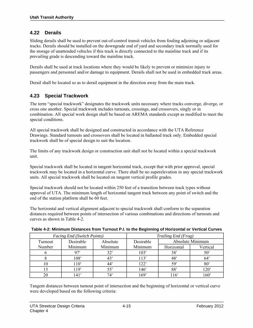
Utah Transit Authority
UTA Streetcar Design Criteria 4-15 February 2012 Chapter 4
4.22 Derails Sliding derails shall be used to prevent out-of-control transit vehicles from fouling adjoining or adjacent tracks. Derails should be installed on the downgrade end of yard and secondary track normally used for the storage of unattended vehicles if this track is directly connected to the mainline track and if its prevailing grade is descending toward the mainline track. Derails shall be used at track locations where they would be likely to prevent or minimize injury to passengers and personnel and/or damage to equipment. Derails shall not be used in embedded track areas. Derail shall be located so as to derail equipment in the direction away from the main track.
4.23 Special Trackwork The term “special trackwork” designates the trackwork units necessary where tracks converge, diverge, or cross one another. Special trackwork includes turnouts, crossings, and crossovers, singly or in combination. All special work design shall be based on AREMA standards except as modified to meet the special conditions. All special trackwork shall be designed and constructed in accordance with the UTA Reference Drawings. Standard turnouts and crossovers shall be located in ballasted track only. Embedded special trackwork shall be of special design to suit the location. The limits of any trackwork design or construction unit shall not be located within a special trackwork unit. Special trackwork shall be located in tangent horizontal track, except that with prior approval, special trackwork may be located in a horizontal curve. There shall be no superelevation in any special trackwork units. All special trackwork shall be located on tangent vertical profile grades. Special trackwork should not be located within 250 feet of a transition between track types without approval of UTA. The minimum length of horizontal tangent track between any point of switch and the end of the station platform shall be 60 feet. The horizontal and vertical alignment adjacent to special trackwork shall conform to the separation distances required between points of intersection of various combinations and directions of turnouts and curves as shown in Table 4-2. Table 4-2: Minimum Distances from Turnout P.I. to the Beginning of Horizontal or Vertical Curves
Facing End (Switch Points) Trailing End (Frog) Turnout Number
Desirable Minimum
Absolute Minimum
Desirable Minimum
Absolute Minimum Horizontal Vertical
6 97′ 32′ 103′ 38′ 50′ 8 108′ 43′ 113′ 48′ 64′ 10 110′ 44′ 122′ 59′ 80′ 15 119′ 55′ 146′ 88′ 120′ 20 141′ 74′ 169′ 116′ 160′
Tangent distances between turnout point of intersection and the beginning of horizontal or vertical curve were developed based on the following criteria:

Utah Transit Authority
UTA Streetcar Design Criteria 4-16 February 2012 Chapter 4
• Desirable distances are obtained by locating the beginning of horizontal or vertical curves at a point that is 75 feet from point of switch or point of frog.
• Absolute minimum distances are obtained by locating the beginning of horizontal or vertical curves 10 feet ahead of the point of switch. Non-superelevated horizontal curves begin beyond the furthest end of the joint bars connecting the running rail to the heel of frog. Vertical curves and superelevated horizontal curves shall not begin until the last long tie of the turnout set on the frog end.
Turnouts are set to provide connections to branch lines, end double tracks, yards, and industry tracks. Crossovers consist of two turnouts located to allow traffic to cross over from one track to another, usually parallel track. Where a pair of crossovers is required it should be set as two single crossovers if at all possible. If this is not possible, a double crossover may be used with the approval of UTA. The size or “number” of the turnout or crossover selected depends upon its purpose, train speeds, and geometric constraints. The normal and maximum operating speeds through the various turnouts designated for use on the project are shown in Table 4-3.
Table 4-3: Turnout Operating Speeds (mph) Turnout Number
Maximum (3" U) Streetcar Vehicle
6 14 10 8 19 15
10 24 20 15 37 30 20 50 45
For design purposes, the normal operating speed shall be used. The usual assignment of turnouts is given in Table 4-4.
Table 4-4: Application of Turnouts Turnout Service Frog Switch
6 13′-0″ Minimum for yard tracks
10 19′-6″ Minimum mainline track turnout Permanent turnbacks preferred where possible in yard
20 39′-0″ Ends of double track or mainline junctions Preferred turnout
Special turnout designs—such as curved frog turnouts and equilateral turnouts—may be advantageous at specific locations. In any such case, the justification for the design shall be rigorously documented and the special design shall not be used without the approval of UTA. The separation distances required between points of intersection of various combinations and directions of turnouts are shown in Tables 4-5 to 4-7. These values are subject to change depending upon determination of final streetcar vehicle characteristics.

Utah Transit Authority
UTA Streetcar Design Criteria 4-17 February 2012 Chapter 4
Table 4-5: Point-to-Point Turnouts, Either Hand
Turnouts Desirable Point-to-Point Distance (feet) (min.)
# 6 into: # 6 # 8w 13′-0″ sw # 8w 19′-0″ sw # 10
102.50 101.67 112.25 112.67
77.50 76.67 87.25 87.67
# 10 into: # 10 # 15 # 20
122.83 133.58 152.46
97.83 108.58 127.46
# 20 into: # 20 182.08 157.08
Table 4-6: Frog-to-Point Turnouts, Same Hand
Leading Turnout Trailing Turnout Frog-to-Point Distance [feet] Desirable (14′-0″
Center or Clear Tie Sets)
12′-6″ Center or Clear Tie Sets
Minimum*
# 6 # 6 # 8w 13′-0″ sw # 8w 19′-6″ sw # 10
84.5839 ** ** **
75.5213** ** ** **
77.4167 76.5833 87.1667 87.5833
# 10 # 10 # 15 # 20
140.3522 122.5000 141.3750
125.3144 122.5000 141.3750
109.2500 120.0000 138.8750
# 20 # 20 280.1775 250.1585 203.3750 * Based on 19′ rail (13′-0″ with # 6 and # 8w 13′-0″ switch) between frog and stock rail. Will require curve beyond heel of switch in lead turnout to provide clearance. ** Do not use, because value is less than minimum.

Utah Transit Authority
UTA Streetcar Design Criteria 4-18 February 2012 Chapter 4
Table 4-7: Frog-to-Point Turnouts, Opposite Hand
Leading Turnout Trailing Turnout Frog-to-Point Distance (feet)
Desirable (Clear Tie Set) Minimum*
# 6 # 6 # 8w 13′-0″ sw # 8w 19′-6″ sw # 10
** ** ** **
77.4167 76.5833 87.1667 87.5833
# 10 # 6 # 8w 13′-0″ sw # 8w 19′-6″ sw # 10 # 15 # 20
101.5833 100.7500
111.3333** 111.7500** 122.5000** 141.3750**
100.3333 99.5000
116.0833 116.5000 127.2500 146.1250
# 20 # 8w 19′-6″ sw # 10 # 15 # 20
206.3333 206.7500 217.5000 236.3750
173.3333 173.7500 184.5000 203.3750
* Based on 19′ rail (13′-0″ with # 6 and # 8w 13′-0″ switch) between frog and stock rail. Will require curve beyond heel of switch in lead turnout to provide clearance. ** Do not use, because value is less than minimum. Special trackwork shall be located at least 10 feet from pedestrian crossings so as to minimize or eliminate the exposure of pedestrians to the operating mechanisms and to open flangeways. Pedestrian crosswalks shall not be located across switches, frogs, and crossing diamonds. Switches shall not be located in areas of vehicular traffic so as to avoid any need for special tongue switch designs and to enhance the safety of UTA employees engaged in switch maintenance. Special trackwork geometry and details should avoid or minimize any requirements for special catenary and signal structures. As all special trackwork is a source of noise and ground-borne vibration, its proposed location shall be determined with due consideration given to those factors. Special trackwork shall be designed for welded joint installation except at insulated joint locations. Where bolted joints in special trackwork are unavoidable, the joints shall be configured to permit epoxy bonding of “D-bar” type joint bars. Running surfaces in special trackwork shall either have or be treated to provide a minimum hardness of Brinell 320. Provisions shall be made during the design of special trackwork for the installation of switch heaters of the “Calrod” tube type. All switches shall be designed to accommodate switch heaters regardless of the location of the specific installation within the system or the need for switch heaters at that location. All power-operated switches shall be equipped with switch heaters at the time of initial construction and provisions shall be made for switch heater installation on all manual switches.

Utah Transit Authority
UTA Streetcar Design Criteria 4-19 February 2012 Chapter 4
Whenever possible switches in paved track shall be of the common AREMA split switch design. Such switches shall be enclosed in a suitable robustly-constructed housing that permits the operation of rubber tired vehicles anywhere in the switch area. Tongue switches shall not be used unless approved UTA.
4.24 Switch Machines—Power Operated and Manual Switches may be operated by power operated switch and lock movements, electrically locked hand-operated machines, or hand-operated trailable switch stands, depending on the location and purpose of the switch. Selection of a switch operating device and the space requirements for such devices shall be coordinated with design of the signal system and Chapter 13.
4.25 Rail Expansion Joints Where thermal forces in the rail cannot be restrained and rail expansion and contraction must be accommodated, rail expansion joints shall be provided. An example is any existing structures that must be protected from longitudinal rail force transfer. Another example is a bridge expansion dam where the rails are embedded in the surface of a paved roadway bridge. Where the amount of rail movement that needs to be accommodated is 2 inches or less, or if the joint is located in a paved bridge deck, a mitered design expansion joint may be used. If rail expansion in excess of 2 inches must be provided, open track rail expansion joints of the sliding rail type shall be provided. Where rail expansion joints are provided in paved track or on a bridge deck, provisions shall be provided for the inspection and maintenance of the joints. The joint housing shall be designed such that it is free draining, and their enclosures shall be designed to accommodate frequent opening for inspection and maintenance flushing.
4.26 At-Grade Crossings Embedded track is preferred for at-grade crossings for a street running streetcar route. For streetcar routes in ballasted track areas, at-grade street crossings should be modular grade crossing panels placed on asphalt pavement or other manufacturer recommended base course. The design of at-grade crossings of yard and secondary track shall be based upon the use of asphalt, concrete, rubber, or bolted timber panels.
4.27 Miscellaneous Track Appurtenances 4.27.1 Buffer Stops The type of track termination shall be determined by the designer and approved by UTA. If the type of track termination to be used is a buffer stop, then the buffer stops shall be designed to engage the vehicle anticlimber without contact with the vehicle coupler and to limit vehicle body damage for the anticipated operating speed. The buffer stop design shall be based on the energy absorption capacity of the friction elements required to stop an LRV based on the following parameters:
• Kinetic energy of a 2-car consist at 10 mph
• Slide area gradient < 1.5%
• Maximum deceleration rate < 1.0 g
• Force limit imposed by shock absorbers < vehicle buff load The buffer stop design shall define the following elements:

Utah Transit Authority
UTA Streetcar Design Criteria 4-20 February 2012 Chapter 4
• Main frame and slave frame steel strength
• Buffer shoes and hardware
• Frame hardware
• Shock absorber head and attachment hardware
• Welding procedure
• Paint thickness and durability
• Field installation and repair procedures 4.27.2 Embedded Track Drains The flangeways provided for the light rail vehicle wheels in embedded track form natural conduits for storm water runoff. In order to prevent the formation of ponds and icing at low points of sag vertical curves, track drains shall be used. Such drains shall also be placed at appropriate intervals along grades to prevent the flangeways from overflowing. A track drain shall be placed on the downgrade end of all embedded track which adjoins ballasted track or direct fixation track so as to minimize fouling of the track ballast with street detritus. Similarly, a track drain shall be provided at the downgrade end of any paved track segment that abuts a segment of direct fixation track so as to prevent street detritus from creating a housekeeping problem in the direct fixation track area. Other locations where the use of track drains may be appropriate shall be identified during final design. 4.27.3 Rail Lubricators Automatic train-sensing rail lubricators shall be considered and evaluated for any trackwork with horizontal curve of 500′ radius or less. In some cases, rail lubricators have reduced significant noise caused by rail transit. Each curve will be evaluated on a case-by-case basis and the decision must be approved by UTA. Part of this evaluation shall be the legal ramifications of greasing the rail in a shared traffic lane. END OF CHAPTER 4.

UTA Streetcar Design Criteria 5-1 February 2012 Chapter 5
Design Criteria UTA Streetcar
Rev No.
Prepared By
Approved By
Approval Date
Document Date
0 T. Jones CCC Feb. 2012 Feb. 2012
Utah Transit Authority Streetcar
Design Criteria
Chapter 5 Civil Work February 2012
Utah Transit Authority
UTA Streetcar Design Criteria 5-1 February 2012 Chapter 5
CHAPTER 5 CIVIL WORK
For the basic civil engineering criteria to be used in design of streetcar transit facilities, including grading, paving, drainage, surveying and right-of-way, refer to the latest version of Chapter 5 of the UTA Light Rail Transit Design Criteria. END OF CHAPTER 5.

Design Criteria UTA Streetcar
Rev No. Prepared By Approved By Approval Date Document
Date 0 T. Jones CCC February 2012 February 2012
Utah Transit Authority Streetcar
Design Criteria
Chapter 6 Utilities
February 2012

Utah Transit Authority
UTA Streetcar Design Criteria 6-i February 2012 Chapter 6
Table of Contents
CHAPTER 6 UTILITIES .................................................................................................................... 1
6.1 General ............................................................................................................................................ 1 6.2 Conflicting Utilities .......................................................................................................................... 1 6.3 Crossing Utilities (Underground) .................................................................................................... 1
6.3.1 Water Services to Residents and Businesses ...................................................................... 2 6.3.2 Communication, Natural Gas, and Electrical Lines ............................................................ 2
6.4 Crossing and Parallel Utilities (Overhead) ..................................................................................... 2 6.5 Parallel Utilities (Underground) ..................................................................................................... 2 6.6 Abandoned Utilities ......................................................................................................................... 3
6.6.1 Abandoned Transmission, Distribution Water, Sanitary Sewer, and Storm Drain Lines ... 3 6.6.2 Abandoned Communication, Gas, and Electrical Lines ..................................................... 3
6.7 Corrosion Protection ....................................................................................................................... 3
Utah Transit Authority
UTA Streetcar Design Criteria 6-1 February 2012 Chapter 6
CHAPTER 6 UTILITIES
6.1 General Potential utility conflicts shall be identified during initial design reviews, with input from municipalities and utility owners. All work required for the relocation , replacement, adjustment and/or abandonment of existing utility facilities and for new facilities within the streetcar right-of-way shall be designed in accordance with the applicable standards and criteria established by the utility owners, applicable State law, and UTA. Requests for future utility crossings must be approved in writing by UTA, and shall comply with Utah Transit Authority’s guidelines. Licenses for crossings will be negotiated through Utah Transit Authority’s Real Estate Division.
6.2 Conflicting Utilities Relocation, replacement, adjustment, protection, and/or abandonment of existing utility facilities shall be required only where an actual conflict exists between the existing utility and the streetcar system. Such conflicts shall be identified by the designer, shall be considered on a case-by-case basis, and shall consider the following factors:
a) Whether the design, construction, maintenance, and/or operation of the proposed streetcar will interfere with an existing utility’s ability, in its existing location, to provide its intended service; and whether the utility was correctly installed in accordance with the criteria established by the utility owner and authorities having jurisdiction
b) Whether the design, construction, maintenance, and/or operation of the streetcar system will interfere with reasonable access to valves, vaults, air vacuums, pressure reducing stations, manholes, man-ways, and hand holes, such that the utilities’ owner is prevented from operating and/or maintaining its utility in accordance with previously established operation and maintenance criteria
c) Whether, upon completion of streetcar construction, a utility in its existing location creates a potential safety hazard to the general public
d) Whether the required minimum cover, as defined by reasonable criteria established by the utility owner, is compromised as the result of grade changes for roadways, track, or structures, for the sole benefit of the Utah Transit Authority
e) Whether soil stresses imposed upon an existing utility by the streetcar system improvements pose a threat to the integrity of the utility facility, considering the depth and location of utility facility, as well as soil type
f) Whether the utility in its existing location will interfere with installation or maintenance of streetcar system improvements
6.3 Crossing Utilities (Underground) Existing utilities which cross the streetcar corridor, that are determined by the Utah Transit Authority to be in conflict with the streetcar system, shall be relocated and/or protected in accordance with the following criteria.

Utah Transit Authority
UTA Streetcar Design Criteria 6-2 February 2012 Chapter 6
Conflicting pressurized liquid lines that cross the streetcar corridor, including but not limited to transmission and distribution water mains, water service laterals greater than 2 inches in diameter, fire protection service lines and pressurized sanitary sewer main lines, shall be installed within a solid steel casing, or other casing material type as determined to be in the best interest of Utah Transit Authority. If split steel casings are installed, all joints, seams, gaps, and interfaces between casing sections shall be either fully welded or bolted to ensure containment of the casing pipe, such that carrier pipe failures are revealed at either end of the casing pipe, outside the streetcar corridor. The replacement utility shall be located such that the top of the casing has adequate cover. Casings shall not be required for any gravity systems, including storm drain and sanitary sewer mains or laterals, or any other lines containing non-pressurized liquids. 6.3.1 Water Services to Residents and Businesses
Where roadway widening, or distribution water main relocations result in the disruption of water service to residents and/or businesses, existing water meters shall be relocated in accordance with reasonable criteria established by the utility owner. Splices in water service laterals up to 2 inches in diameter shall be allowed, provided that splicing material, size, and type match existing laterals, and approved fittings are installed in accordance with the manufacturer’s recommendations. For lateral water service connections to relocated distribution water mains, corporation stops and service saddles shall be provided by the Utah Transit Authority’s General Contractor. 6.3.2 Communication, Natural Gas, and Electrical Lines
Existing utilities shall be lowered in place or looped as required, and sections of HDPE split casings installed such that existing conduit is continuous, and installed to facilitate future removal as necessary.
6.4 Crossing and Parallel Utilities (Overhead) Clearances from the overhead distribution system shall be in conformance with the requirements of Chapter 13 of this Design Criteria, the National Electric Code, the utility owners, American Railway Engineering & Maintenance-of-Way Association (AREMA), the Public Service Commission, and any other authority having jurisdiction. Transmission and distribution electrical or communication lines attached to poles in accordance with previously established lease agreements shall be relocated and adjusted in place or looped underground, as determined to be in the best interest of the Utah Transit Authority.
6.5 Parallel Utilities (Underground) Utilities located within the streetcar corridor, that contain a pressurized liquid or that are determined to be in conflict, shall either be replaced with a replacement utility located outside the corridor as required, to connect back to its existing line, or installed within a steel casing, steel split casings, or other casing material as determined to be in the best interest of the Utah Transit Authority. If reasonable access to hand-holes, manholes, vaults, or access man-ways is not compromised, the utility may remain in its existing location, as determined by the Utah Transit Authority. Gravity systems shall be designed in accordance with utility owners’ established criteria, and installed between manholes at a depth such that the original flowline is maintained and lateral connections from residences and businesses, or curb inlet boxes shall meet minimum grade requirements.

Utah Transit Authority
UTA Streetcar Design Criteria 6-3 February 2012 Chapter 6
Utilities located outside the streetcar corridor, and determined by the Utah Transit Authority to be in conflict with roadway widening, including hand-holes; gas and electrical vaults; and communication vaults, lines, and cables previously located within park strips, mow strips, or behind sidewalks, and as a direct result of streetcar construction are now located in roadways or sidewalks, shall be modified in accordance with the following.
a) Fiberglass communication hand holes located in a roadway shall be replaced with concrete hand holes which comply with HS-20 loading requirements. If their new location is sidewalks, existing fiberglass hand holes shall be adjusted to finished grade such that no tripping hazard is present.
b) Concrete vaults that must be lowered, (if allowed by the utility owner and sufficient head room clearance is available), shall have their top deck saw-cut and removed, and a replacement concrete deck cast to match the new roadway or sidewalk grades.
c) Fiber optic communication lines shall be lowered in place, utilizing available slack. Split casings shall be installed such that existing conduits are continuous.
d) Communication cables shall be lowered in place if possible, or looped between existing pedestals to achieve sufficient depth.
e) Risers shall be adjusted and manholes ringed to match finished grade.
6.6 Abandoned Utilities 6.6.1 Abandoned Transmission, Distribution Water, Sanitary Sewer, and Storm Drain Lines
a) Any abandoned piping, resulting from the resolution of a previously conflicting utility, shall be abandoned in place. Abandoned pipe larger than 8 inches in diameter shall have the pipe ends plugged with concrete to mitigate any conduit effects, and potential future settlement associated with the ground water movement.
b) Abandoned manholes, resulting from the resolution of a previously conflicting utility shall be abandoned in place. The ring and cover shall be returned to the municipality having jurisdiction. The top manhole section shall be removed to a minimum depth of 3 feet below top of sub-grade. The interior influent and effluent piping shall be plugged with concrete and the remaining sections backfilled and compacted in accordance with the municipalities established criteria.
6.6.2 Abandoned Communication, Gas, and Electrical Lines
All abandoned communication lines and gas and electrical lines shall be abandoned in place. Abandon manholes in accordance with section 6.6.1.
6.7 Corrosion Protection Corrosion protection shall be the responsibility of the utility owner. If UTA is performing any work related to the utility and if the utility owner deems that corrosion protection is required, it is the responsibility of the utility owner to specify to UTA its requirements for corrosion protection. UTA shall not be responsible in any manner whatsoever for the adequacy of such corrosion protection. Designers should refer to Chapter 16 for Corrosion Protection of underground utilities. END OF CHAPTER 6.

Design Criteria UTA Streetcar
Rev No. Prepared By Approved By Approval Date Document
Date 0 T. Jones CCC February 2012 February 2012
Utah Transit Authority Streetcar
Design Criteria
Chapter 7 Structural February 2012

Utah Transit Authority
UTA Streetcar Design Criteria 7-1 February 2012 Chapter 7
CHAPTER 7 STRUCTURAL
7.1 General For the basic design criteria for structures, including bridges, stations, retaining walls, buildings, catenary structures, drainage structures, construction structures, and miscellaneous structures, refer to the latest version of Chapter 7 of the UTA Light Rail Transit Design Criteria. END OF CHAPTER 7.
Design Criteria UTA Streetcar
Rev No.
Prepared By
Approved By
Approval Date
Document Date
0 T. Jones CCC February 2012 February 2012
Utah Transit Authority Streetcar
Design Criteria
Chapter 8 Stations
February 2012

Table of Contents
CHAPTER 8 STATIONS ................................................................................................................... 3
8.1 General ............................................................................................................................................ 3 8.1.1 Scope ............................................................................................................................... 3 8.1.2 Codes and Standards ........................................................................................................... 3 8.1.3 General Design Parameters ................................................................................................. 3
8.2 Platform Geometrics ........................................................................................................................ 4 8.2.1 Configuration ...................................................................................................................... 4 8.2.2 Platform Height ................................................................................................................... 4 8.2.3 Platform Surface and Edge Treatment ................................................................................ 4
8.3 General Station Requirements ......................................................................................................... 4 8.3.1 Weather Protection ............................................................................................................. 4 8.3.2 Fare Vending Equipment .................................................................................................... 4 8.3.3 Patron Amenities ................................................................................................................. 5 8.3.4 Signing ............................................................................................................................... 5 8.3.5 Advertising.......................................................................................................................... 5 8.3.6 Maintenance Space and Procedures .................................................................................... 5 8.3.7 Communication and Power Conduits ................................................................................. 5
8.4 Circulation Elements ....................................................................................................................... 6 8.4.1 Pedestrian Patterns .............................................................................................................. 6 8.4.2 Elements of Vertical Circulation ........................................................................................ 6
8.4.2.1 Ramps ..................................................................................................... 6 8.4.2.2 Stairs ..................................................................................................... 7
8.5 Lighting ............................................................................................................................................ 7 8.6 General Materials and Finishes Guidelines .................................................................................... 7
8.6.1 Safety ............................................................................................................................... 7 8.6.2 Ease of Maintenance ........................................................................................................... 8
8.6.2.1 Cleaning ..................................................................................................... 8 8.6.2.2 Repair or Replacement ........................................................................................... 8
8.6.3 Resistance to Vandalism ..................................................................................................... 8 8.6.4 List of Finish Materials ....................................................................................................... 8
8.6.4.1 Acceptable Paving Materials ................................................................................. 8 8.6.4.2 Unacceptable Paving Materials ............................................................................. 9 8.6.4.3 Acceptable Metallic Surfaces and Finishes ........................................................... 9 8.6.4.4 Unacceptable Metallic Surface Finishes ................................................................ 9 8.6.4.5 Acceptable Canopy Materials ................................................................................ 9 8.6.4.6 Unacceptable Canopy Materials ............................................................................ 9

Utah Transit Authority
UTA Streetcar Design Criteria 8-3 February 2012 Chapter 8
CHAPTER 8 STATIONS
8.1 General 8.1.1 Scope This section establishes specific guidelines and standards for the design of stations. The stations will be at-grade (except in special cases), standardized and cost effective in design. Elements discussed in this section include the design of platforms or platform access. Guidelines are provided for the selection of materials. The design of the stations shall be standardized. Equipment, shelters, platform features, structural elements, and signage used shall be the same system-wide and compatible with UTA’s existing identity. Deviations from standard design elements may be required for specific sites, but must be approved by UTA before design proceeds. 8.1.2 Codes and Standards Applicable codes and standards include the most current edition of the following documents:
• International Building Code (IBC)
• Uniform Plumbing Code
• Uniform Mechanical Code
• NFPA, Life and Safety Code
• NFPA, Life Safety for Transit Systems
• Uniform Fire Code
• Uniform Federal Accessibility Standards
• ANSI A 117.1
• Occupational Safety and Health Standards (OSHA) (29FR Part 1910)
• Uniform Electrical Code
• Americans with Disabilities Act (ADA) Where no provisions are made in the codes for particular features of the design the best architectural practice shall be followed, with the prior approval of UTA. 8.1.3 General Design Parameters The facilities must be able to serve the needs of patrons efficiently, economically, safely, conveniently, and comfortably. These stations shall also provide for the traditional requirements of public transit systems: identity in neighborhoods or downtown areas as a location for public transit, shelter from severe weather, and cover and/or screening from average weather conditions. In designing the facilities, the anticipated growth and long-term life of the system shall be considered. Function and life cycle consideration are important, as are aesthetics and the overall quality and character of the facilities. Station design shall be compatible in design with the immediate vicinity and reflective of the regional context of the Salt Lake Valley. Stations shall be standardized to provide a consistently understandable experience for transit users. Standard graphic information systems are especially important. Consistency reduces inventories for

Utah Transit Authority
UTA Streetcar Design Criteria 8-4 February 2012 Chapter 8
replacement parts and equipment for maintenance and costs. UTA has adopted standard graphic criteria as contained in Appendix 1. In all segments, it is essential that great care be taken in coordinating final design with UTA, the affected communities and neighborhoods, adjacent property owners or developers, public agencies, or community groups having jurisdiction over or significant interest in the human environment and design of facilities at stations and along routes. Coordination with the development plans and master plans of local communities and neighborhoods is essential to blending the transit system into the urban fabric of the Salt Lake Valley, and in assuring that UTA needs and community needs are met.
8.2 Platform Geometrics 8.2.1 Configuration In general, platforms shall be located in the sidewalk adjacent to the travel path. Disabled persons will be able to board the streetcar through the use of low-floor vehicles and raised sidewalks, if necessary. The platform length available for boarding and alighting shall be for a one-car train. If a center platform is warranted, the design shall consider location, configuration, current ADAAG accessibility guidelines, and clear space around station amenities. The front edge of the platform shall extend to within 3 inches of the threshold of the streetcar doors so as to comply with ADAAG. 8.2.2 Platform Height The platform height shall be 8 inches above the top of rail. All platforms shall have a drainage cross slope to the trackside of 1.5% maximum. 8.2.3 Platform Surface and Edge Treatment The surface of all platforms shall be non-skid and of long-wearing weather resistant materials. The tactile tile near the platform edge shall be yellow, high-strength tiles. Tiles shall be designed to accept the bridge plate of a low-floor vehicle. This strip shall meet current ADA requirements, currently 24 inches wide from the car clearance envelope on tangent or curved platforms. The warning strip shall not impede the passage of a wheelchair but shall be sufficiently rough or different to be felt by sight impaired patrons.
8.3 General Station Requirements 8.3.1 Weather Protection Generally, there shall be pre-fabricated shelters over portions of each platform. The shelters shall be composed of durable components currently in use in the Wasatch Front Region, and economical to repair or replace. 8.3.2 Fare Vending Equipment Fare-vending equipment will be installed at all stations. 120 Vac, single-phase power will be provided for all equipment requiring electric power. Spare conduit will be provided to accommodate future additions and changes. The equipment shall be located near main entry points or centered on the platform to minimize the length of travel for patrons. Refer to Chapter 15 for detailed information.

Utah Transit Authority
UTA Streetcar Design Criteria 8-5 February 2012 Chapter 8
8.3.3 Patron Amenities Elements associated with platforms may be provided by UTA or an outside establishment.
• Trash Receptacles—Shall be provided at all stations.” Trash receptacles shall be sensitive to Homeland Security Safety Standards.
• Communications—See Chapter 15 of this criteria for description of the communications system. A minimum of two conduits will be placed along the length of the station for each station. These conduits will be used for future message/communications systems. No antenna shall be located on station platforms.
8.3.4 Signing The basic objectives of the system signing is to guide persons to and through the system in the most efficient, safe, and user friendly manner using simple, strong, and precise style, organized in systematic and sensible layouts. Sign communication shall be further enhanced by proper placement of signs and careful determination of sign dimensions and quantities. Signs shall be standard throughout the streetcar system. Each station will have a system map and schedule. The signing is to emphasize the streetcar system identity and be consistent with existing UTA signage. They shall be designed according to ADA standards. 8.3.5 Advertising The station shelter and other elements may be able to accommodate advertising. The application may vary by neighborhood and local ordinances. Advertising displays shall conform to a system-wide standard of frames and finishes subject to local jurisdictions. 8.3.6 Maintenance Space and Procedures All station maintenance will be performed by UTA personnel during revenue hours. Major pieces of maintenance and repair equipment will be moved to the station from a central facility where equipment, supplies, and materials are stored. 120 V receptacles will be provided for use during maintenance. 8.3.7 Communication and Power Conduits Each center platform will contain two 2″ conduits for UTA communication wire and fiber on the south or east side of the platform. Additionally, each center platform will contain two additional conduits for 2″ conduits for power on the north or west side of the platform. These conduits will run from the power control cabinet and along the entire length of the platform, terminating at a pull box on each end of the run. Appropriately spaced pull boxes will be installed. On side platforms, the communication conduits will be located on the inside (trackside) of the platform and the power/sensor conduits will be located on the outside of the platforms. Conduits in the platform area will be concrete encased. Pull boxes should be located outside of primary walk paths. Lateral conduits will be provided from the communications and power conduits to each of the following locations: ticket vending machines, phones, shelters (for lights, public address, and passenger information signs), stand-alone message signs, light poles, and kiosks.

Utah Transit Authority
UTA Streetcar Design Criteria 8-6 February 2012 Chapter 8
8.4 Circulation Elements The stations in the system are functional spaces for patron circulation, waiting, and access to the transit vehicle. Therefore, the stations shall be designed as efficient conduits to accommodate peak demands without undue delay. 8.4.1 Pedestrian Patterns The criteria listed in this section are minimum guidelines relevant to pedestrian circulation and they should not supplant the logic of a better functional solution, should it develop. There are three distinct groups that must be considered in the design of pedestrian circulation:
• Regular users
• Infrequent users
• Disabled users The three groups move through the system in varying ways:
• Regular users move quickly with a minimum of guidance
• Infrequent users move easily with great reliance on signs for guidance
• Disabled users move slowly with the guidance required depending on the frequency of use and the degree of the disability
The following general principles shall be employed to accommodate these varying demands:
• Stations should be designed to directly and safely accommodate anticipated pedestrian movements. The direction of circulation elements shall be as obvious as possible to aid recognition.
• Queuing space is desirable ahead of every barrier, and in front of ticket vending machine (TVM) installations.
• No obstructions shall be permitted within the main pedestrian flow.
• Shelter areas shall have sufficient transparency to give adequate visual surveillance of these spaces for user safety and to discourage vandalism.
8.4.2 Elements of Vertical Circulation All vertical circulation elements shall be designed in accordance with ADA requirements. Ramps shall be provided at all changes of grade and be available to any rider needing or wishing to utilize them. 8.4.2.1 Ramps Generally, ramps will be used to transition small elevation differences such as from the curb to a platform. According to ADAAG, a path of travel with a slope greater than 1:20 shall be considered a ramp. Ramps shall be provided to the platforms as required for topographic changes and shall comply with provisions of ADAAG. For any ramp where the vertical rise between landings exceeds 6 inches and/or the slope of ramp is between 1:12 and 1:20, handrails shall be provided on each side of any ramp. The handrails shall be designed in accordance with ADAAG. The surface of ramps shall be slip-resistant.

Utah Transit Authority
UTA Streetcar Design Criteria 8-7 February 2012 Chapter 8
8.4.2.2 Stairs The minimum width of stairs for public use shall be 48 inches. The minimum length of landing for straight-line stairs shall be 54 inches.
8.5 Lighting The station lighting shall include all lighting required to light the platform and pedestrian walkways associated with the station. Lighting design may be subject to local jurisdictional design criteria. Artificial lighting shall be provided for safety in all open station site areas with due consideration for adjacent land uses. The average maintained footcandle values are indicated in Table 8-1. The average footcandles listed may require reduction at station locations in low-density residential areas. Light fixtures shall be provided with a cutoff feature to eliminate candle power at high angles. Artificial light sources to obtain the required footcandle levels shall be no higher than 15 feet in stations. Light fixture size, pole height, and number of poles shall be selected to optimize footcandle and aesthetic design criteria. Design consideration should be given to place lighting on separate circuits in order to phase lighting levels and provide reliability. Lighting control shall be accomplished by the use of photocell units and contactors. This will provide operational cost savings.
Table 8-1: Illumination Design Level Mode Change Location Average Maintained Footcandles at Ground Level Station Platforms 3–5 Park-and-Ride Areas Local jurisdictional criteria Entrance and Exit Roads Local jurisdictional criteria Kiss-and-Ride Areas Local jurisdictional criteria Pedestrian Walkways Local jurisdictional criteria Bus Loading Zones Local jurisdictional criteria Note: Uniformity for all locations should be vertical/horizontal = 0.75–1.25/1, where vertical is footcandles up to 8′-0″, and horizontal is footcandles at ground level.
8.6 General Materials and Finishes Guidelines The following basic requirements and criteria have been established for the finish of public areas within the system. While convenience, comfort, and attractiveness shall be considered in the selection and application of these finishes, safety, durability, and economy are essential attributes. 8.6.1 Safety
• Flammability and smoke generation hazard from fire shall be reduced by using finish materials with minimum burning rates, smoke generation, and toxicity characteristics consistent with Code requirements as noted in IBC and NFPA 101, Life Safety Code, 1988 (or most current edition).
• Hazard from dislodgment due to temperature change, vibration, wind, seismic forces, aging, or other causes, shall be reduced by using proper fasteners and adequate bond strength.

Utah Transit Authority
UTA Streetcar Design Criteria 8-8 February 2012 Chapter 8
• Pedestrian safety shall be increased and the presence of the disabled shall be recognized by using floor materials with non-slip qualities. Stairways, platform edge strips, ramps, and areas around equipment shall have high non-slip properties.
• Edging and flooring shall be electrically insulated. No grounded metallic surface shall be installed within 5′-0″ of the edge of the platform adjacent to trains.
• Electrical protection and conductors shall be sized in accordance with NFPA 70 (NEC).
• All current-carrying enclosures shall be effectively grounded. 8.6.2 Ease of Maintenance 8.6.2.1 Cleaning Facilitate cleaning and reduce cleaning costs by the use of materials that do not soil or stain easily, which have surfaces that are easy to clean in a single operation using standard equipment and cleaning agents, and on which minor soiling is not apparent. 8.6.2.2 Repair or Replacement To reduce inventory and maintenance costs, materials shall be used that can be easily repaired or replaced without undue cost or interference with the operation of the streetcar system. For example, hose bibs, electrical outlets, lighting fixtures and lamps, glass or plastic lights, etc., shall be standardized with commonly available sizes and finishes to ease inventory stocking or direct purchase. 8.6.3 Resistance to Vandalism Materials and details that do not encourage vandalism and that are difficult to deface, damage, or remove shall be used. All surfaces exposed to the public shall be finished in such a manner that the results of casual vandalism can be readily removed with common maintenance techniques. 8.6.4 List of Finish Materials This list shall apply to all areas of public use. The use of items listed as “acceptable” is subject to location and environmental considerations. All materials shall conform to the requirements of ADA. 8.6.4.1 Acceptable Paving Materials
• Non-slip or other textured-finish concrete
• Stamped-pattern concrete
• Bituminous paving (in carefully defined areas or where required for consistency with adjacent paving)
• Quarry tiles (non-slip)
• Paver brick (dense hard)
• Selected artificial stone materials
• Precast pavers
• Natural stone pavers Other paving materials may be acceptable, subject to UTA and local jurisdictional approval.

Utah Transit Authority
UTA Streetcar Design Criteria 8-9 February 2012 Chapter 8
8.6.4.2 Unacceptable Paving Materials
• Synthetic resin surfacing
• Standard cement terrazzo
• Bituminous surfacing, except as noted above
• Marble
• Wood products 8.6.4.3 Acceptable Metallic Surfaces and Finishes
• Stainless steel (areas of high pedestrian use)
• Black wrought iron
• Unfinished galvanized steel (where there is no contact with pedestrian touch)
• Factory applied hard-baked enamel
• Color anodized aluminum (where there is a low degree of pedestrian touch)
• Pressure-treated heavy timber and glue-laminated wood (min. 3″ dimension) 8.6.4.4 Unacceptable Metallic Surface Finishes Jobsite-painted metals are unacceptable metallic surface finishes. 8.6.4.5 Acceptable Canopy Materials
• Steel with factory finished baked enamel
• Safety glass
• Silicone or Teflon coated fiberglass (where out of reach of vandals)
• Painted enamel
• Anodized aluminum 8.6.4.6 Unacceptable Canopy Materials
• Ordinary glass
• Uncoated fabric
• Ordinary plastics
• Combustible materials END OF CHAPTER 8.
Design Criteria UTA Streetcar
Rev No.
Prepared By
Approved By
Approval Date
Document Date
0 T. Jones CCC February 2012 February 2012
Utah Transit Authority Streetcar
Design Criteria
Chapter 9 Landscaping
February 2012

Utah Transit Authority
UTA Streetcar Design Criteria 9-1 February 2012 Chapter 9
CHAPTER 9 LANDSCAPING
9.1 General For guidance regarding the landscaping of streetcar facilities, refer to Chapter 9 of the latest UTA Light Rail Transit Design Criteria. END OF CHAPTER 9.

Utah Transit Authority
Design Criteria UTA Streetcar
Rev No. Prepared By Approved By Approval Date Document Date
0 T. Jones CCC February 2012 February 2012
Utah Transit Authority Streetcar
Design Criteria
Chapter 10 Traffic Control and
Signal Priority System February 2012

Utah Transit Authority
UTA Streetcar Design Criteria 10-1 February 2012 Chapter 10
CHAPTER 10 TRAFFIC CONTROL AND SIGNAL PRIORITY SYSTEM
10.1 Introduction In most situations, streetcar vehicles will be operating on existing streets mixed with general traffic and shall utilize existing traffic signals and existing traffic control devices. Special rail signals will be provided only in cases where special track work or vehicle movements necessitate them. If a streetcar project necessitates the use of LRT signals, and/or if the project will utilize streetcar signal priority, refer to the latest version of Chapter 10 of the UTA Light Rail Transit Design Criteria for guidance.
10.2 Signs Signs shall be installed in the proper locations as specified in the MUTCD and appropriate local standards. Where a sign is to be installed in a non-standard location, or is a non-standard sign, the installation shall be approved by the local jurisdiction and by UTA.
10.3 Pavement Markings Traffic marking requirements are to be obtained from the standard plans and drawings of each jurisdiction. Where local standards are not available, the MUTCD shall be used. All pavement markings shall comply with the requirements of ADA. END OF CHAPTER 10.
Design Criteria UTA Streetcar
Rev No. Prepared By Approved By Approval Date Document Date
0 T. Jones CCC February 2012 February 2012
Utah Transit Authority Streetcar
Design Criteria
Chapter 11 Streetcar Vehicles
February 2012
Utah Transit Authority
UTA Streetcar Design Criteria 11-i February 2012 Chapter 11
Table of Contents
CHAPTER 11 STREETCAR VEHICLE ........................................................................................... 1
11.1 General Description......................................................................................................................... 1 11.2 Vehicle Environment ........................................................................................................................ 1
11.2.1 Environmental Criteria ....................................................................................................... 1 11.2.2 Wayside Characteristics and Civil Alignment Constraints ................................................. 1 11.2.3 Overhead Contact System (OCS) Power Interface ............................................................. 1
11.2.3.1 Traction Power Interface ....................................................................................... 1 11.2.3.2 Vehicle Voltage Limits .......................................................................................... 1
11.3 Vehicle Design Constraints .............................................................................................................. 1 11.3.1 Safety Requirements ........................................................................................................... 1 11.3.2 Shock and Vibration Criteria .............................................................................................. 2
11.3.2.1 Car Body Mounted Components ........................................................................... 2 11.3.2.2 Truck Frame Mounted Components ...................................................................... 2 11.3.2.3 Axle-Mounted Components ................................................................................... 3
11.3.3 Weight Constraints and Design Loading ............................................................................ 3 11.3.4 Vehicle Identification ......................................................................................................... 3 11.3.5 Acoustic Noise Limits ........................................................................................................ 3
11.3.5.1 Wayside Noise Limits ............................................................................................ 3 11.3.5.2 Car Interior Noise Limits ....................................................................................... 3
11.3.6 Electromagnetic Compatibility ........................................................................................... 4 11.3.6.1 Radiated Emission Limits ...................................................................................... 4 11.3.6.2 Conductive Emission Limits .................................................................................. 4 11.3.6.3 Inductive Emission Limits ..................................................................................... 4 11.3.6.4 Susceptibility ..................................................................................................... 4
11.3.7 Smoke and Flammability Requirements ............................................................................. 4 11.3.8 Provisions for Individuals with Disabilities ........................................................................ 5 11.3.9 Lighting Safety Provisions .................................................................................................. 5 11.3.10 Ride Quality ........................................................................................................................ 5 11.3.11 Adhesion Requirements ...................................................................................................... 5
11.4 Light Rail Vehicle Dimensions ......................................................................................................... 6 11.4.1 Exterior Dimensions ........................................................................................................... 6 11.4.2 Other Dimensions ............................................................................................................... 6 11.4.3 Dynamic Outline ................................................................................................................. 6
11.5 Vehicle Performance ........................................................................................................................ 6 11.5.1 Acceleration Requirements ................................................................................................. 7 11.5.2 Speed Requirements ........................................................................................................... 7 11.5.3 Deceleration Requirements ................................................................................................. 7 11.5.4 Towing Requirements ......................................................................................................... 7 11.5.5 Jerk Limit ............................................................................................................................ 7 11.5.6 Slip/Slide Protection ........................................................................................................... 8 11.5.7 Load Weight System ........................................................................................................... 8

Utah Transit Authority
UTA Streetcar Design Criteria 11-ii February 2012 Chapter 11
11.6 Car Body .......................................................................................................................................... 8 11.6.1 Strength Requirements ........................................................................................................ 8 11.6.2 Roof ............................................................................................................................... 8 11.6.3 Jacking and Hoisting Provisions ......................................................................................... 9 11.6.4 Wheelchair Accommodations ............................................................................................. 9
11.7 Couplers and Draft Gear ................................................................................................................. 9 11.7.1 Mechanical Couplers .......................................................................................................... 9 11.7.2 Draft Gears .......................................................................................................................... 9 11.7.3 Electrical Couplers .............................................................................................................. 9
11.8 Operator’s Cab .............................................................................................................................. 10 11.8.1 Operator’s Console ........................................................................................................... 10 11.8.2 Bypass and Cutout Switches ............................................................................................. 10
11.9 Passenger Doors ............................................................................................................................ 10 11.9.1 Normal Operation ............................................................................................................. 10 11.9.2 Emergency Operation ....................................................................................................... 10
11.10 Air Comfort System ........................................................................................................................ 10 11.11 Lighting System .............................................................................................................................. 11
11.11.1 Interior Lighting ................................................................................................................ 11 11.11.2 Exterior Lighting ............................................................................................................... 11 11.11.3 Emergency Lighting ......................................................................................................... 11
11.12 Auxiliary Electrical Equipment ...................................................................................................... 11 11.12.1 Power Collection ............................................................................................................... 11 11.12.2 Auxiliary Power Supply .................................................................................................... 12 11.12.3 Low-Voltage DC Power Supply ....................................................................................... 12 11.12.4 Storage Battery ................................................................................................................. 12 11.12.5 Emergency Loads ............................................................................................................. 12
11.13 Propulsion System .......................................................................................................................... 13 11.13.1 General ............................................................................................................................. 13 11.13.2 Drive Configuration .......................................................................................................... 13 11.13.3 Continuous Rating ............................................................................................................ 14 11.13.4 Short-Time Overload Rating............................................................................................. 14 11.13.5 Electric Braking ................................................................................................................ 14 11.13.6 Cooling ............................................................................................................................. 14 11.13.7 Ground Brush .................................................................................................................... 14
11.14 Trucks and Suspension ................................................................................................................... 14 11.15 Friction Braking System ................................................................................................................ 15
11.15.1 Service Braking ................................................................................................................. 15 11.15.2 Emergency Braking .......................................................................................................... 15
11.16 Communications System ................................................................................................................ 15 11.16.1 Train Radio ....................................................................................................................... 15 11.16.2 Public Address System ..................................................................................................... 15 11.16.3 Intercom ............................................................................................................................ 15
11.17 Automatic Train Protection ........................................................................................................... 15

Utah Transit Authority
UTA Streetcar Design Criteria 11-iii February 2012 Chapter 11
11.18 In-Service Support ......................................................................................................................... 16 11.18.1 General ............................................................................................................................. 16 11.18.2 Manuals ............................................................................................................................. 16 11.18.3 Shop and Portable Test Equipment and Special Tools ..................................................... 17 11.18.4 Spare Parts ........................................................................................................................ 17 11.18.5 Training ............................................................................................................................. 17 11.18.6 Acceptance Testing ........................................................................................................... 17
11.18.6.1 General ................................................................................................... 17 11.18.6.2 Pre-Delivery Acceptance Testing .................................................................. 18 11.18.6.3 Pre-Delivery Performance Testing ................................................................ 18 11.18.6.4 Final Acceptance Testing .............................................................................. 18
11.18.7 Warranty Period ................................................................................................................ 18

Utah Transit Authority
UTA Streetcar Design Criteria 11-1 February 2012 Chapter 11
CHAPTER 11 STREETCAR VEHICLE
11.1 General Description This section describes the basic attributes of the streetcar vehicles to be used by UTA. The vehicles shall be fully compatible with the existing vehicles for mixed consist operation. Information contained herein is intended to generally define the composite aspects of the vehicle which relate to the interfaces between the vehicle and other portions of the UTA system. Because the vehicle is a composite of “off-the-shelf” equipment, these criteria apply to the limits that the design of available equipment must meet. In turn, the actual vehicle must generate criteria affecting traction power and structural detailed design, and this data should be available promptly after the procurement is decided. Until that decision is rendered, the following vehicle criteria shall apply with the understanding that changes will be forthcoming when the specific actual vehicle is defined.
11.2 Vehicle Environment 11.2.1 Environmental Criteria Refer to Chapter 2, Environmental Criteria. 11.2.2 Wayside Characteristics and Civil Alignment Constraints Refer to Chapter 3, Track Alignment and Vehicle Clearance. 11.2.3 Overhead Contact System (OCS) Power Interface 11.2.3.1 Traction Power Interface
• Nominal OCS voltage: 750 volts, DC
• Maximum operating voltage: 900 volts, DC
• Minimum operating voltage: 525 volts, DC 11.2.3.2 Vehicle Voltage Limits The vehicle upper voltage limit shall be set to maximize the benefits of regeneration, but not to exceed 950 volts DC. The vehicle equipment shall be designed to operate at a lower limit of 450 volts DC. All equipment shall be capable of operating without damage at any voltage between these two limits. Outside of these limits, vehicle systems shall be shut down, which shall cause an emergency brake application.
11.3 Vehicle Design Constraints 11.3.1 Safety Requirements Items, the failure of which could result in critical/catastrophic hazard, are designated “safety critical.” A critical/catastrophic hazard is a situation which could result in a severe injury or fatality to patrons or UTA personnel, or which could result in major system, vehicular, or environmental damage. Specific safety critical items identified for the vehicle are:
• Removing positive tractive effort during braking
• Braking and safe braking distances
• Prevention of initial motion with any brake applied
Utah Transit Authority
UTA Streetcar Design Criteria 11-2 February 2012 Chapter 11
• Fire-resistance requirements
• Inhibiting motion when doors are open
• Prevention of door opening during motion
• Direction control
• Automatic train protection (to be considered as an option) The vehicle contractor shall identify any additional safety critical items incorporated in its proposed design. 11.3.2 Shock and Vibration Criteria All car components shall operate without damage in the normal rail environment and shall not produce excessive vibrations. Equipment design and mounting arrangements shall be based on a specific mounting location on the car and shall consider the influence of adjacent components as well as normal vehicle operation. In addition to any shock or vibration encountered in normal operation, all equipment shall withstand the vibration levels defined in the following sections and, under these specified conditions, shall not cause vertical or horizontal vibrations anywhere on the vehicle floor, walls, ceiling, panels, and seat frames in excess of the following:
• Below 1.4 Hz—Maximum deflection (zero to peak) of 2.5 mm (0.10 inch), based on insuring that the vibration of the car body elements are not sensed by patrons
• Between 1.4 Hz to 20 Hz—Maximum peak acceleration of 0.01 g (vibrations of this amplitude may be perceptible, but not uncomfortable to patrons)
• Above 20 Hz—Maximum peak velocity of 0.75 mm/sec. (0.03 in/sec.); this limit is primarily designed to limit noise radiated from vibrating car body components
In addition, the vibration of any traction motor shall conform with the requirements of IEEE Standard No. 11, Sections 13.2.2 and 13.2.3. 11.3.2.1 Car Body Mounted Components These components shall be designed and mounted to withstand:
• Continuous sinusoidal vibrations of 0.4 g rms at any frequency from 1 Hz to 100 Hz in the three major axes
• Randomly oriented shock impulses of 3 g peak with duration from 4 milliseconds to 10 milliseconds
11.3.2.2 Truck Frame Mounted Components These components shall be designed and mounted to withstand, without fatigue or deterioration for a vehicle life of 30 years, the normally occurring random shock and vibration magnitudes at the support points on the truck frame. These magnitudes shall be considered to be 1.0 g rms with a crest factor (ratio of peak to rms acceleration level) of 5, within the frequency range from 20 Hz to 10 kHz in all directions, and shocks occurring up to 100 times per operating day to 20 g peak in the vertical axis and 6 g peak in the lateral axis with pulse durations from 4 milliseconds to 10 milliseconds.

Utah Transit Authority
UTA Streetcar Design Criteria 11-3 February 2012 Chapter 11
11.3.2.3 Axle-Mounted Components Components shall be designed to withstand, as a minimum:
• Continuous random vibrations of 10 g rms within the frequency range of 10 Hz to 10 kHz in all directions
• Shock pulses of 100 g in each major axis, with durations from 0.5 milliseconds to 2 milliseconds occurring approximately 100 times per day
11.3.3 Weight Constraints and Design Loading As a baseline, the composite vehicle shall not weigh more than the following:
• AW0 (Empty Car) 43.1 metric tons (98,000 lb)
• AW1 (Seated Load) AW0 + 75 passengers at (111,000 lb) each
• AW2 AW1 + 90 standees (125,000 lb)
• AW3 AW2 + 45 standees (132,000 lb) = 61.7 metric tons (136,000 lb)
• AW4 (Crush) AW3 + 45 standees (139,000 lb) The minimum acceptable number of seats per vehicle is 60. Equipment installation shall be arranged such that its weight is evenly distributed to the maximum practical extent. The vehicle, complete with all necessary apparatus, shall meet the following criteria:
• The difference of static weight, as measured under each motor truck, shall not be greater than 2%.
• The difference of static weight between the A-end and B-end of the vehicle shall not exceed 900 kg (2,000 lb).
• The lateral imbalance shall not exceed 290 kg-m (25,000 in-lb). 11.3.4 Vehicle Identification Vehicles shall be sequentially numbered from the first production car to the last. 11.3.5 Acoustic Noise Limits 11.3.5.1 Wayside Noise Limits Wayside noise produced by a two-car consist with all auxiliary systems operating shall not exceed the following limits:
• At 90 km/h (55 mph) 80 dBA at 15 m (50 ft)
• At 32 km/h (20 mph) 68 dBA at 15 m (50 ft)
• Each auxiliary system alone 67 dBA at 4.6 m (15 ft)
• Vehicle stationary 60 dBA at 15 m (50 ft) 11.3.5.2 Car Interior Noise Limits The average noise level in the interior of the car shall not exceed the following levels with all equipment operating:
• At 90 km/h (55 mph) 72 dBA
• At 64 km/h (40 mph) 70 dBA

Utah Transit Authority
UTA Streetcar Design Criteria 11-4 February 2012 Chapter 11
• Vehicle stationary 68 dBA 11.3.6 Electromagnetic Compatibility Harmonic currents produced by the vehicle in the running rails shall not exceed 30% of the minimum guaranteed threshold of the associated signal circuits. Signal circuits shall have a fundamental frequency of 100 Hz. Audio frequency overlays shall also be used for at-grade crossing protection. Electrical, electronic, and communications systems and sub-systems shall operate without either suffering or causing interference which may impact system operations and/or safety because of electromagnetic interference. 11.3.6.1 Radiated Emission Limits Vehicles shall not produce any radiated emissions that will violate FCC Rules and Regulations, Part 15.25. For design validation, vehicles shall not produce radiated emission levels above those permitted by Figure 10-2 (UM05), Curve 2 of MIL-STD-461B, when measured at 30.5 m (100 ft) from the track centerline and tested in accordance with UMTA-MA-06-0153-85-11.
• From 0.01 MHz to 30 MHz, the maximum permissible interference limit shall not exceed 20 dB above the limit of Figure 22 (RE05) of MIL-STD-461A.
• From 30 MHz to 88 MHz, the maximum permissible interference limit shall be 58 dB above 1 mV/m/MHz bandwidth.
• From 88 MHz to 1,000 MHz, the maximum permissible interference limit shall be 68 dB above 1 mV/m/MHz bandwidth.
11.3.6.2 Conductive Emission Limits
• From 0 Hz to 40 Hz, 10 A maximum
• From 40 Hz to 120 Hz, 1 A maximum
• From 120 Hz to 320 Hz, 10 A maximum
• Above 320 Hz, the maximum permissible conductive emission limits shall be under a smooth curve through 10 A at 320 Hz, 0.08 A at 2 kHz, and 0.0046 A at 7 kHz
11.3.6.3 Inductive Emission Limits The inductive emissions shall be limited to a maximum of 20 millivolts rms, rail-to-rail, at all frequencies between 20 Hz and 20 kHz. 11.3.6.4 Susceptibility All systems shall be designed and installed to tolerate acceptable levels of electromagnetic interference and have adequate protection against false energization, miscodes, and improper codes caused by any and all electromagnetic emission sources. 11.3.7 Smoke and Flammability Requirements All materials and construction shall meet the requirements of the latest edited version of NFPA 130, Chapter 4, Vehicles, and related appendices. The ceiling structural assembly shall meet a 30-minute minimum endurance rating when tested in accordance with ASTM E 119. The floor structural assembly shall meet a 15-minute minimum endurance rating when tested in accordance with ASTM E 119.

Utah Transit Authority
UTA Streetcar Design Criteria 11-5 February 2012 Chapter 11
Total BTU content shall be no more than 90,000,000 BTU per vehicle. Heat release rate shall be no more than 45,000,000 BTU/hour per vehicle. 11.3.8 Provisions for Individuals with Disabilities Provisions for individuals with disabilities shall be per the rules and regulations of the Americans with Disabilities Act (ADA) effective October 7, 1991, and shall comply with all applicable requirements for new transit facilities. Only the minimum requirements for design and construction are incorporated into the ADA Accessibility Guidelines. Related regulatory provisions of other government agencies having jurisdiction shall be used for additional guidelines in designing and constructing streetcar vehicles to be free of architectural or other transportation barriers. The latest editions of the code, regulation, and standard that are applicable at the time the design is initiated shall be used. If a new edition or amendment to a code, regulation or standard is issued before the design is completed, the design shall conform to the new requirements to the extent practical, except that it shall conform to the new requirements if required by the government agency enforcing the revised or new code, regulation, or standard. Reference:
• Federal Register 49 CFR Parts 27, 37 and 38, Transportation for Individuals with Disabilities, Final Rule
• U.S. Architectural and Transportation Barriers, Compliance Board, Technical Assistance Manual 11.3.9 Lighting Safety Provisions All exterior lights and emergency interior lighting shall be capable of operating from battery power for up to 60 minutes in the event of an auxiliary power supply failure. 11.3.10 Ride Quality The vehicle design shall be free from objectionable vibration and shock. All equipment mounted in the passenger area shall be free from resonance to avoid audible and visual annoyance. The ride quality shall be evaluated according to ISO 2631. The rms acceleration values shall not exceed the “2½ to 4 hours reduced comfort level” boundaries derived from Figure 2a (vertical) and Figure 3a (horizontal) of ISO 2631-1978 (E). The roll stiffness of the vehicle body, when subjected to lateral accelerations, shall not exceed 20 dpg (degrees per g). 11.3.11 Adhesion Requirements The vehicle adhesive weight and the efficiency of the slip/slide system shall be such that the adhesion required by the positive tractive force to start a vehicle from a standstill anywhere on the system, and the adhesion required by the negative tractive force to decelerate the car from any speed down to a standstill, will not cause unacceptable damages to the vehicle wheels under track slippery conditions. Track slippery conditions are defined as those conditions which may cause the actual coefficient of adhesion to be, without sanding, less than 20% but not less than 10%. With sanding, track slippery
Utah Transit Authority
UTA Streetcar Design Criteria 11-6 February 2012 Chapter 11
conditions are defined as those conditions which may cause the actual coefficient of adhesion to be less than 28%, but not less than 17%.
11.4 Light Rail Vehicle Dimensions 11.4.1 Exterior Dimensions Vehicle dimensions shall not exceed the following (all heights are from top of rail):
• Length over the coupler faces 26,975 mm (88.5 ft)
• Exterior width 2,650 mm (104 in)
• Car floor height (nominal) 1004 mm (39.5 in)
• Top of roof mounted equipment 3,800 mm (150 in)
• Top of pantograph in locked down position 3,730 mm (146.85 in) 11.4.2 Other Dimensions
• Ceiling height from floor 2,083 mm minimum (82 in)
• Width of side door openings 1,220 mm minimum (48 in) 1,320 mm maximum (52 in)
• Height of side door openings 1,930 mm minimum (76 in)
• Pantograph operating range 4,064 mm minimum (13 ft 4 in) 7010 mm maximum (23 ft)
• Wheel diameter (new) 710 mm (28 in)
• Wheel diameter (worn) 660.4 mm (26 in) 11.4.3 Dynamic Outline Minimum under-car clearances under worst case vertical curve crest and sag (for minimum radius of vertical curve, see Chapter 3), worst case loading and worst case wheel wear shall be as follows:
• Under-car mounted equipment 101.6 mm (4 in)
• Under-truck mounted equipment 63.5 mm (2.5 in) For OCS design purposes, vehicle dynamic movements shall be constrained within the following limits:
• Maximum body roll during normal operation 6 degrees (3 degrees to each side)
• Maximum pantograph sway with respect +/– 50.8 mm (2 in) with pantograph to car body during normal operation at 5,791 mm (19 ft)
• Lateral bearing displacement +/– 50.8 mm (2 in)
11.5 Vehicle Performance Streetcar performance is defined for operations on dry level tangent track, AW2 loading for acceleration performance and AW3 loading for deceleration performance, over the specified range of wheel wear, with no significant wind. OCS voltage shall be at the nominal 750 Vdc for propulsion. In braking, the braking system shall perform as specified at any line voltage within the specified range.

Utah Transit Authority
UTA Streetcar Design Criteria 11-7 February 2012 Chapter 11
Dry track conditions are defined as those conditions where the actual coefficient of adhesion is at least 25% without sanding. 11.5.1 Acceleration Requirements
• Acceleration rate (initial) from 0 to 32 km/h 1.34 m/s/s (3 mph/s) (20 mph)
• Time to 32 km/h (20 mph) 8.5 seconds maximum
• Time to 90 km/h (55 mph) 40 seconds maximum 11.5.2 Speed Requirements
• Minimum balancing speed 90 km/h (55 mph)
• Maximum operating speed 92 km/h (57 mph)
• Nominal operating speed 90 km/h (55 mph) 11.5.3 Deceleration Requirements
• Minimum average safe service brake rate 0.67 m/s/s (1.5 mph/s)
• Average service brake rate from 1.07 m/s/s (2.4 mph/s) 90 km/h (55 mph) to 64 km/h (40 mph)
• Average service brake rate from 1.34 m/s/s (3 mph/s) 64 km/h (40 mph) to 4.8 km/h (3 mph)
• Average service brake rate from 0.67 m/s/s (1.5 mph/s) 4.8 km/h (3 mph) to 0
• Average emergency brake rate from 1.78 m/s/s (4 mph/s) 90 km/h (55 mph) to 48 km/h (30 mph)
• Average emergency brake rate from 2.00 m/s/s (4.5 mph/s) 48 km/h (30 mph) to 0
11.5.4 Towing Requirements A fully functioning train shall be capable, with no damage to its equipment, of pushing or pulling an inoperative train of the same length, with both trains loaded at AW3. An inoperative train is defined as a dead train. Due to the reduced adhesive weight, the acceleration rate can be reduced to the limits required to operate in accordance with the track characteristics. The deceleration rate can also be reduced, but not to be less than the safe braking rate. Under slippery track conditions, sanding may be used to make the actual adhesion at least equal to the adhesion required by either the positive tractive force during the propulsion mode, or the negative tractive force during the braking mode. 11.5.5 Jerk Limit Under all normal operating conditions, the rate of change of vehicle acceleration or deceleration shall not be less than 0.89 m/s/s/s (2 mph/s/s) or greater than 1.34 m/s/s/s (3 mph/s/s). Failure of the jerk limiting system shall not limit the braking effort. Emergency brake applications and any associated ramp out of propulsion shall not be jerk-limited. Reduction of propulsion effort due to

Utah Transit Authority
UTA Streetcar Design Criteria 11-8 February 2012 Chapter 11
power interruption does not need to be jerk-limited. Reapplication of propulsion effort following a power interruption shall be jerk-limited. 11.5.6 Slip/Slide Protection A slip/slide protection system shall be provided. A slip/slide protection system is defined as a system which reduces the tractive effort, either positive during propulsion or negative during braking, upon detection of a slip or a slide and until the slip or the slide disappears. Ideally, the reduction of tractive effort would bring the required coefficient of adhesion down to the same value as the actual coefficient of adhesion. The efficiency of the slip/slide system shall be at least 75% on a slippery track with an adhesion coefficient of 10%, when operating with friction brake only in either service braking or emergency braking. 11.5.7 Load Weight System A load weight system shall be provided. The load weight system shall provide the vehicle load information to the propulsion and braking systems, in order for the propulsion system to achieve the required acceleration from AW0 to AW2 and for the braking system to achieve the required deceleration from AW0 to AW3.
11.6 Car Body The car body shall be constructed of low alloy high tensile (LAHT) steel. All exterior surfaces of the LAHT steel shall be primed and painted. All interior metal surfaces shall be coated with a primer for corrosion protection. Vehicle end caps may be fabricated using molded fiberglass. 11.6.1 Strength Requirements The yield strength of all structural members shall withstand a uniform vertical load of AW3 minus AW0 with at least a 50% margin. The vehicle shall withstand a static compression end load of two times AW0 acting along the longitudinal centerline of the vehicle and distributed at about the center of the anticlimber. The combined stresses from the above vertical load and the above static compression end load shall not cause any deformation in any part of the car body and shall not exceed 90% of the yield value of the material used. Each anticlimber shall have at least three ribs. 11.6.2 Roof The roof sheathing and structure shall be capable of supporting without any permanent deformation concentrated loads of at least 113 kg (250 lb), as would be applied by a person walking on the roof. Areas adjacent to the pantograph shall support concentrated loads of at least 227 kg (500 lb). A roof mat shall be installed on the roof to provide an anti-slip walking surface. In addition, an electrically insulated area on the roof, under and around the pantograph mounting, shall be installed to provide a safe working area for maintenance personnel.

Utah Transit Authority
UTA Streetcar Design Criteria 11-9 February 2012 Chapter 11
11.6.3 Jacking and Hoisting Provisions The vehicle shall be equipped with jacking and hoisting provisions. The vehicle may be jacked as a unit. Each body section may be jacked separately, with the body bending at the articulation section(s). The maximum angle of bending of the articulation shall not exceed 3 degrees. Any combination of diagonal jacking shall not cause any structural or cosmetic damage. Jacking pads shall be provided for:
• Portable jacks
• In-floor hoists
• The articulation Jacking at the anticlimber positions shall be permitted. The vehicle design shall include provisions for re-railing the center truck. 11.6.4 Wheelchair Accommodations Provisions shall be made to comply with the latest ADA requirements.
11.7 Couplers and Draft Gear 11.7.1 Mechanical Couplers Couplers shall automatically couple on contact within a gathering range of 76 mm (3 in) and with a maximum of 8 degrees of total rotational mismatch. Couplers shall withstand AW0 car coupling at speeds up to 4.8 km/h (3 mph) without automatic release or damage. The coupler system shall withstand a buff or draft load of 79.38 metric tons (175,000 lb) with no permanent deformation. 11.7.2 Draft Gears At buff or draft loads above 68.04 metric tons (150,000 lb), draft gears shall collapse to allow the anticlimbers to meet while absorbing the moment resulting from the load. 11.7.3 Electrical Couplers Spring-loaded silver-plated contacts, which are redundant on each side of the coupler, shall carry all necessary electrical signals from car to car. Electrical couplers shall use a mirror image configuration such that any end of any car can be coupled to any end of any other car. Electrical coupler heads shall be protected by weatherproof covers, which shall automatically swing clear when a coupling is initiated.

Utah Transit Authority
UTA Streetcar Design Criteria 11-10 February 2012 Chapter 11
11.8 Operator’s Cab There shall be two completely functional operator’s cabs per car. Trainline control shall permit only one cab to act as the active controlling cab in a train consist. The operator’s cab shall be of a design based on appropriate human factors. The operator’s cab dimensions shall ensure safe and optimal operator performance for operators in the range of the 5th to 95th percentile of the general population, both female and male. 11.8.1 Operator’s Console The operator’s console shall contain all controls and annunciators to safely operate the train. 11.8.2 Bypass and Cutout Switches One panel within each operator’s cab shall contain sealed safety bypass switches that shall permit manual operation of the train in the event of failure of major subsystems. An adequate annunciation shall be provided to clearly indicate to the operator which bypass switch is in a bypass position.
11.9 Passenger Doors There shall be four passenger doors per side in each car. Door operators shall be electrically operated. The door opening function shall be interlocked with the propulsion and brake systems, such that motion is not permitted when any door in a train consist is not fully closed, and such that brakes are applied when the door opening function is enabled by the operator or any door in a train consist is not fully closed. 11.9.1 Normal Operation Doors shall normally be opened individually by passenger-operated push-buttons, after release (enable function) by the train operator after the train stops at a station. The operator shall normally control the closing of the doors. In addition, the operator shall have the capability of controlling opening and closing of the doors on either side of the train. 11.9.2 Emergency Operation An emergency manual door release shall be provided near each door. Activation of the emergency door release device shall unlock the door for manual opening, prevent motion, and place the train in an irretrievable full service brake application. In addition, any attempt to activate an emergency door release device in motion shall reapply closing power to the door at that location in order to prevent its manual opening.
11.10 Air Comfort System The air comfort system shall include heating, ventilating, and air conditioning to assure passenger comfort in the operating environment. The air comfort system shall be equipped with a single control unit. Maximum interior relative humidity shall not exceed 55%. Except in layover mode where the ventilation shall not be used, ventilation shall be provided all the time to ensure that a minimum comfortable amount of fresh air is delivered to the vehicle.

Utah Transit Authority
UTA Streetcar Design Criteria 11-11 February 2012 Chapter 11
The heating system shall include overhead and floor heaters in the passenger compartment, and cab heaters in the operator’s cabs. The heating system shall be designed to maintain the interior temperature around 20 °C (68 °F). The heating system shall also be provided with a “layover” mode. In the layover mode, a selected number of floor heaters shall be used to maintain the interior temperature around 13 °C (55 °F). In the layover mode, the car interior temperature shall be controlled by a separate layover thermostat. Heated surfaces which may come in contact with passengers shall not exceed 51.7 °C (125 °F). With an exterior ambient temperature of 23 °C (73 °F) to 35 °C (95 °F), the air conditioning system shall maintain the vehicle interior temperature between 23 °C (73 °F) and 26 °C (78 °F). With exterior temperatures above 35 °C (95 °F), the vehicle interior temperature shall be at least 9 °C (17 °F) lower than the outside temperature. The air conditioning units shall be mounted on the vehicle roof and may be individually controlled by the single air comfort control unit.
11.11 Lighting System The lighting system includes all interior and exterior lights, with the exception of annunciator lights. 11.11.1 Interior Lighting The passenger compartment shall be lit by continuous fluorescent lighting fixtures, which shall not extend into the operator’s cabs. The operator’s cabs shall be lit by separately controlled lamps. 11.11.2 Exterior Lighting All exterior lights shall be trainlined for proper illumination and identification at night. The vehicle shall be equipped with three headlights, two taillights and three stoplights at each end. The center headlight shall be a 200-watt PAR 56 railroad lamp. The stoplights shall operate at approximately 150% of the intensity of the taillights. 11.11.3 Emergency Lighting The emergency lights shall be all exterior lights, all cab lights, all lights above the doors, and 25% of the interior lights. The emergency lights shall remain functional for at least 60 minutes in the event of a failure of the auxiliary power supply using battery power back-up.
11.12 Auxiliary Electrical Equipment 11.12.1 Power Collection Power from the overhead contact system shall be collected by a roof-mounted pantograph which uses a double shoe arrangement of proven service design. The double shoe arrangement shall include a spring-loaded suspension. A lateral load of 29.50 kg (65 lb) on the pantograph shoe axis with the pantograph at the maximum operating height shall not cause the shoe to deflect more than 38 mm (1.50 in). The

Utah Transit Authority
UTA Streetcar Design Criteria 11-12 February 2012 Chapter 11
pantograph shall be mounted as close as possible from the center of the vehicle to minimize lateral movement under all track conditions. A breakaway design shall be used so that the pantograph is sacrificial to the overhead wire in case of snagging. The pantograph shall be raised by a spring, with an appropriate damping device to minimize bouncing. The upward contact force shall be approximately 7.25 kg (16 lb). The pantograph shall be electrically lowered and latched. An electrically released lock-down mechanism shall be provided to prevent movement of a locked pantograph. Means shall be provided to manually release the lock-down mechanism, and raise, lower, and latch the pantograph from inside the vehicle if electrical power is not available. The pantograph design shall include provisions for clearing ice from the OCS. The pantograph may be unpowered while clearing ice. 11.12.2 Auxiliary Power Supply A variable duty cycle static inverter shall be provided to develop 3 phase 60 Hz 208/120 V auxiliary power from the 750 Vdc primary power. The voltage regulation shall be within +/− 5%, and the frequency shall be maintained within +/− 5 Hz. Alternatively, the voltage-to-frequency ratio should be maintained within +/− 1% at all loads. Capacity shall be sized to handle worst case loads for any season or operating conditions with an additional 10% margin. 11.12.3 Low-Voltage DC Power Supply A nominal 37.5 Vdc low-voltage power supply (LVPS) shall be provided to power systems and subsystems controls, exterior lighting and annunciators, and door operators. In addition, the LVPS shall also maintain the storage battery charge. Output of the LVPS shall be regulated within +/− 10% from zero to full load. 11.12.4 Storage Battery A nickel-cadmium battery shall be provided to initially start the vehicle and to power emergency loads during failures of the LVPS or when the primary 750 Vdc power is lost. The capacity shall be sufficient to power emergency loads for at least 1 hour of operation. 11.12.5 Emergency Loads Emergency loads are defined as follows:
• Emergency lights (see Section 11.11.3)
• Doors
• Communications
• Propulsion and braking controls
• Trainline controls
• Track brake(s)
• Pantograph
Utah Transit Authority
UTA Streetcar Design Criteria 11-13 February 2012 Chapter 11
• Coupler control
• Cab lighting, controls, and annunciators
• Horn(s)
• ATP (as an option)
11.13 Propulsion System 11.13.1 General The propulsion system shall conform to one of the following configurations:
• Sweeping frequency thryistor chopper with DC traction motors
• Fixed frequency thryistor chopper with DC traction motors
• AC inverter control with AC traction motors The requirements for an AC propulsion system shall include a variable voltage, variable frequency voltage source microprocessed controlled 3-phase inverter using pulse width modulation and square wave regulation techniques. Inverters shall use modular construction technique based on a limited number of individual building blocks. At least one inverter per motor truck shall be provided. The propulsion system shall have the following characteristics:
• Separate and independent slip/slide control for each powered truck
• Separate and independent slide control for the unpowered truck
• Separate friction brake interface and brake blending control for each truck
• Design and construction of all AC traction motors, gear units, and power conditioning equipment such that a 804,500 km (500,000 miles) overhaul cycle is achieved without intermediate maintenance activity beyond routine inspection and servicing
• Ability to operate cars successfully and reliably on the OCS with high-voltage transients and extensive arcing and repetitive occurrences of intermittent contact
• Ability to continue operations for extended periods of time with reduced acceleration and safe braking rate when a powered truck is cut out
11.13.2 Drive Configuration Drive systems shall be configured with one motor per axle on each powered truck, using a resiliently mounted parallel gear drive arrangement with overspeed protection. The maximum motor speed shall allow continuous operation at 92 km/h (57 mph) with fully worn wheels on a level tangent track. All motors, gear units, and couplings shall be fully interchangeable from motor axle to motor axle and between powered trucks. Gears shall have a minimum life of 1,609,000 km (1,000,000 miles), and shall be fabricated from high quality gear steel designed and treated/hardened in accordance with AGMA 240.01–Gear Material Manual.

Utah Transit Authority
UTA Streetcar Design Criteria 11-14 February 2012 Chapter 11
11.13.3 Continuous Rating The propulsion system continuous rating shall be based on the worst case continuous duty cycle derived from the route profile, and stop/start operation in mixed traffic and extended operation at extreme OCS voltages. The continuous thermal rating shall be determined for an AW2 loading level and shall provide a margin of at least 10% above that required for continuous duty cycle, to include the ripple power amplitude and the ripple frequency present on the inverters. 11.13.4 Short-Time Overload Rating The short-time overload rating for the propulsion system shall be determined as follows:
• Following operation of a two-car train with AW2 loads for 2 hours under the continuous rating conditions specified in Section 11.13.3, the propulsion system shall be capable of continuing operation for 1 more hour with one car in cutout, without exceeding component temperature ratings.
• The propulsion system shall also have the capability of towing or pushing a dead train of equal length, without exceeding component temperature ratings. The contractor shall provide the subsequent performance restrictions for approval by UTA.
11.13.5 Electric Braking Electric braking shall be sufficient to meet the required performance without any addition of friction braking for loads up to and including AW2, at all speeds from 90 km/h (55 mph) down to the electric brake fade out speed (approximately 4.8 km/h, or 3 mph). In the double track areas, if the overhead contact system is receptive to regenerative current such that the propulsion system exceeds an internally set limit, electric braking shall be blended between regenerative and rheostatic braking, with priority to regenerative braking. Above AW2 load, electric braking shall be blended with friction braking in order to provide the required performance up to and including AW3. 11.13.6 Cooling If required, cooling air for traction motors shall be ducted and screened from the side of the car body, sufficiently high above the top of rail to minimize the entry of snow and road dust. Cooling air for power semi-conductors, if used, shall not come in contact with energized components or surfaces. Chlorinated fluorocarbon cooling methods shall not be used. 11.13.7 Ground Brush Each axle of all trucks shall be provided with two ground brushes and holders. Ground brush life shall be a minimum of 241,350 km (150,000 miles).
11.14 Trucks and Suspension The vehicle shall be supported by three two-axle trucks (two motor trucks and one trailer truck), with a coil spring secondary suspension. The primary suspension shall be by means of chevron or approved equivalent elastomeric springs, with a maximum vertical resonant frequency of 12 Hz.
Utah Transit Authority
UTA Streetcar Design Criteria 11-15 February 2012 Chapter 11
Trucks of proven design shall be connected to the car body through positive mechanical means such that the trucks shall be raised with the car body when it is lifted.
11.15 Friction Braking System The friction braking system shall be an electro-hydraulic disc brake system. One hydraulic power unit per truck shall be provided. 11.15.1 Service Braking Friction braking shall act as a supplement to the electric braking below the electric brake fade out speed and at loads above AW2. Above AW2, friction braking and electric braking shall be blended to provide the required braking rates. Friction braking only shall be used in case of unavailability of electric braking. In that case, friction braking shall be capable of providing the required service brake rate at any speed and for all loads up to AW3. A parking brake system shall be provided that is capable of holding an AW0 vehicle on a 4% grade for 30 days with no electric power available on the vehicle. 11.15.2 Emergency Braking Friction braking shall be the primary braking system for emergency stops. Emergency braking shall include track brake application and sanding, as required to meet the specified emergency brake rates.
11.16 Communications System The communications system shall be composed of the train radio, the public address system and the intercom. 11.16.1 Train Radio The train radio system shall be completely integrated with the vehicle. The radio system shall allow communications between the train operator and the controller. The radio shall be capable of transmitting an operator-initiated silent alarm. 11.16.2 Public Address System The public address system shall allow the train operator to make announcements to passengers inside the train, and to persons waiting outside on the platform when the train is in a station. 11.16.3 Intercom The passenger intercom system shall allow a two-way conversation between the train operator and any of the energized on-board passenger intercom stations. There shall be two passenger intercom stations in each car, located at each end near each wheelchair position.
11.17 Automatic Train Protection As an option, automatic train protection may be used. Train control circuits shall use
Utah Transit Authority
UTA Streetcar Design Criteria 11-16 February 2012 Chapter 11
100 Hz signals for block signaling, and audio frequency overlays at grade crossings. Additionally, a train to wayside communications system may be used. The LRV shall be designed not to interfere with these applications.
11.18 In-Service Support 11.18.1 General As a minimum, the in-service support shall include:
• Manuals
• Shop and portable test equipment and special tools
• Initial spare parts and recommended parts stocking level
• Training
• Acceptance testing
• Warranty 11.18.2 Manuals Operating manuals shall be provided and shall include:
• General familiarization with the vehicle
• Operation of the vehicle
• Trouble symptoms and diagnostic methods
• Recovery procedures
• Emergency procedures Maintenance manuals shall be provided and shall include “running maintenance manuals” and “heavy repair maintenance manuals.” Running maintenance manuals shall provide:
• Information required to perform on-board servicing, and periodic servicing and adjustment
• Trouble diagnosis, to include troubleshooting guides
• Piping and wiring schematics
• Information required for using test equipment and special tools Heavy maintenance manuals shall contain detailed descriptions and analyses of components, such that maintenance personnel can effectively repair, replace or overhaul each component and subsystem. Parts Catalogs shall also be provided. Parts catalogs shall identify each component and shall give its contractor’s part number, suppliers, source control documents, and drawings. The format and content of each of the above documents and the number of copies to be provided shall be submitted by the contractor for UTA approval.

Utah Transit Authority
UTA Streetcar Design Criteria 11-17 February 2012 Chapter 11
11.18.3 Shop and Portable Test Equipment and Special Tools The contractor shall provide all necessary special test equipment and special tools for UTA personnel to properly perform in-service maintenance, testing, and adjustment. 11.18.4 Spare Parts The contractor shall deliver spare parts such that the delivery shall be keyed to the vehicle delivery schedule and will provide a sufficient inventory to support the operating needs of UTA at all times until the expiration of the warranty period. The contractor shall also determine the final inventory required to support on-going car maintenance after the expiration of the warranty period. The subsequent recommended final spare parts list, including detailed costs, shall be submitted to UTA sufficiently in advance in order for UTA to complete the recommended stocking level before the expiration of the warranty period. 11.18.5 Training The contractor shall provide a training program for a sufficient number of selected UTA instructors, supervisors, operations personnel, and maintenance personnel, of a quality and depth sufficient to permit UTA to safely and satisfactorily operate, service, and maintain the vehicles, and to train other and future staff in the operation and maintenance of the vehicles. The training program shall be conducted at UTA facilities, and should include classroom and “hands-on” instruction. The contractor shall, within 90 days after award of the contract, submit a training program outline and a schedule for UTA approval that shall identify milestones for submitting the course outlines, lesson plans, instructor and student guides, audio-visual aids, mock-up(s), simulator(s), written and practical tests, and conducting classes. As training materials are being developed, the contractor shall work closely with UTA staff to ensure UTA standards, with respect to the training program organization, content, and overall quality of training aids are met. All training materials shall become the property of UTA at the completion of the training program. The contractor shall be responsible for the condition of these materials for the duration of the training program, and shall replace all damaged materials unless the damage resulted from neglect by UTA personnel. Written and audio-visual training aids shall be updated as required. 11.18.6 Acceptance Testing 11.18.6.1 General After all qualification and quality control tests have been successfully completed by the contractor prior to shipment of the vehicle(s) to UTA, acceptance testing shall be performed at UTA facilities by the contractor, prior to delivery of the cars to UTA for final acceptance, and by UTA for final acceptance of the vehicles. The purpose of these tests is to verify that no damage has occurred during shipment and to ensure that cars are properly adjusted and in suitable conditions for operation by UTA in revenue service. Test procedures shall be submitted to UTA for approval. UTA will, at its option, witness all tests performed by the contractor. Therefore, the contractor shall notify UTA, in writing and at least two weeks prior to each test, of the date, time, and location the test will be performed.

Utah Transit Authority
UTA Streetcar Design Criteria 11-18 February 2012 Chapter 11
11.18.6.2 Pre-Delivery Acceptance Testing After receipt of each car at UTA’s facilities, and before it is operated, it shall be jointly inspected by UTA and the contractor. The contractor shall make such adjustments, repairs, or replacements as required for proper operation before pre-delivery acceptance testing may begin. Should a repair or replacement be required which is a result of inadequate pre-shipment testing, the contractor shall provide UTA with evidence that the inadequacy is corrected prior to shipment of additional vehicles. As a minimum, the following pre-delivery acceptance tests shall be performed by the contractor:
• Insulation resistance and high potential tests
• Functional tests (all subsystems)
• Coupler tests (alignment and level)
• Static clearance tests (trucks and carbody)
• Interface tests with other systems (track, OCS power, and ATP)
• Dynamic clearance tests 11.18.6.3 Pre-Delivery Performance Testing After successful completion of the pre-delivery acceptance tests, the contractor shall demonstrate the dynamic performance of each vehicle, as specified in Section 11.5, and that all design constraints have been satisfied, as specified in Section 11.3. After successful completion of the pre-delivery performance testing on the first four cars, compliance with the towing requirements specified in Section 11.5.4 shall be demonstrated by the contractor only once, using two active cars and two dead cars. 11.18.6.4 Final Acceptance Testing After successful completion of the pre-delivery acceptance and performance testing on the first car, cars having successfully completed their pre-delivery testing shall be delivered to UTA for final acceptance testing. In order to facilitate and support the UTA final acceptance testing program, the contractor shall provide UTA with the instrumentation required to monitor at least two cars, the procedures to connect and use the instrumentation, and the technical support which may be required until completion of the final acceptance program. Each car will be given an operational “burn in” of about 1,600 km (1,000 miles) by UTA. During “burn-in,” performance, current and voltage parameters, as well as date, time, and distance will be recorded continuously on separate channels on magnetic tapes. Upon issuance of a notice of rejection by UTA, rejected cars will be turned back to the contractor for appropriate corrective actions. After the contractor has completed its corrective work, UTA will complete retesting of the cars. 11.18.7 Warranty Period The contractor shall submit for UTA approval its plan to show how it intends to support UTA during the warranty period. The duration of the warranty period shall be clearly stated. The cost of the warranty period shall be included in the vehicle contract price. If applicable, optional additional extended warranty periods with their associated costs may be proposed by the contractor.

Utah Transit Authority
UTA Streetcar Design Criteria 11-19 February 2012 Chapter 11
END OF CHAPTER 11.
Design Criteria UTA Streetcar
Rev No. Prepared By Approved By Approval Date Document Date
0 T. Jones CCC February 2012 February 2012
Utah Transit Authority Streetcar
Design Criteria
Chapter 12 Electric Traction Power
Supply and Distribution System February 2012

Utah Transit Authority
UTA Streetcar Design Criteria 12-1 February 2012 Chapter 12
CHAPTER 12 ELECTRIC TRACTION POWER SUPPLY AND DISTRIBUTION SYSTEM
12.1 Introduction For design criteria regarding the functional and design requirements for the supply and supervision of traction power for streetcar transit, refer to Chapter 12 of the latest version of the UTA Light Rail Transit Design Criteria. END OF CHAPTER 12.

Utah Transit Authority
Design Criteria UTA Streetcar
Rev No. Prepared By Approved By Approval Date Document Date
0 T. Jones CCC February 2012 February 2012
Utah Transit Authority Streetcar
Design Criteria
Chapter 13 Signal System
February 2012

Utah Transit Authority
UTA Streetcar Design Criteria 13-1 February 2012 Chapter 13
CHAPTER 13 SIGNAL SYSTEM
13.1 General If a signal system is to be employed in a streetcar transit project, refer to Chapter 13 of the latest version of the UTA Light Rail Transit Design Criteria for guidance on functional design requirements, the interface criteria with other work, and the selected hardware technologies for the signal system. END OF CHAPTER 13.
Design Criteria UTA Streetcar
Rev No. Prepared By Approved By Approval Date Document Date
0 T. Jones CCC February 2012 February 2012
Utah Transit Authority Streetcar
Design Criteria
Chapter 14 Communications
February 2012

Utah Transit Authority
UTA Streetcar Design Criteria 14-1 February 2012 Chapter 14
CHAPTER 14 COMMUNICATIONS
14.1 General For design criteria regarding the communications systems of streetcar transit projects, refer to Chapter 14 of the latest version of the UTA Light Rail Transit Design Criteria. END OF CHAPTER 14.
Utah Transit Authority
\
Design Criteria UTA Streetcar
Rev No. Prepared By Approved By Approval Date Document Date
0 T. Jones CCC February 2012 February 2012
Utah Transit Authority Streetcar
Design Criteria
Chapter 15 Fare Collection Equipment
February 2012

Utah Transit Authority
UTA Streetcar Design Criteria 15-1 February 2012 Chapter 15
CHAPTER 15 FARE COLLECTION EQUIPMENT
15.1 General For design criteria regarding fare collection equipment on streetcar transit projects, refer to the latest version of Chapter 15 of the UTA Light Rail Transit Design Criteria. END OF CHAPTER 15.

Design Criteria UTA Streetcar
Rev No. Prepared By Approved By Approval Date Document Date
0 T. Jones CCC February 2012 February 2012
Utah Transit Authority Streetcar
Design Criteria
Chapter 16 Corrosion Control
February 2012

Utah Transit Authority
UTA Streetcar Design Criteria 16-1 February 2012 Chapter 16
CHAPTER 16 CORROSION CONTROL
16.1 General For design criteria regarding corrosion control on streetcar transit projects, refer to the latest version of Chapter 16 of the UTA Light Rail Transit Design Criteria. END OF CHAPTER 16.

Design Criteria UTA Streetcar
Rev No. Prepared By Approved By Approval Date Document Date
0 T. Jones CCC February 2012 February 2012
Utah Transit Authority Streetcar
Design Criteria
Chapter 17 Yard and Shop
February 2012

Utah Transit Authority
UTA Streetcar Design Criteria 17-1 February 2012 Chapter 17
CHAPTER 17 YARD AND SHOP
17.1 General For design criteria regarding yard and shop facilities for streetcar transit projects, refer to the latest version of Chapter 17 of the UTA Light Rail Transit Design Criteria. END OF CHAPTER 17.

Design Criteria UTA Streetcar
Rev No. Prepared By Approved By Approval Date Document Date
0 T. Jones CCC February 2012 February 2012
Utah Transit Authority Streetcar
Design Criteria
Chapter 18 Rail Trails February 2012

Utah Transit Authority
UTA Streetcar Design Criteria 18-1 February 2012 Chapter 18
CHAPTER 18 RAIL TRAILS
For design criteria regarding trails for streetcar transit projects, refer to the latest version of Chapter 18 of the UTA Light Rail Transit Design Criteria. END OF CHAPTER 18.

Design Criteria UTA Streetcar
Rev No. Prepared By Approved By Approval Date Document Date
0 T. Jones CCC February 2012 February 2012
Utah Transit Authority Streetcar
Design Criteria
Chapter 19 Pedestrian Crossings
February 2012

Utah Transit Authority
UTA Streetcar Design Criteria 19-1 February 2012 Chapter 19
CHAPTER 19 PEDESTRAIN CROSSINGS
For design criteria regarding pedestrian crossings for streetcar transit projects, refer to the latest version of Chapter 19 of the UTA Light Rail Transit Design Criteria. END OF CHAPTER 19.