utstarcom - erp solution for small and medium … project/documents/docum… · utstarcom inc....
TRANSCRIPT

UTStarcomMPower EMS User Guide
Release 1.2Revision A
Product Order No. MP-EUG-1.2-A
UTStarcom Inc.

Copyright© 2004 UTStarcom Inc.. All rights reserved.
This Manual is the property of UTStarcom Inc. and is confidential. No part of this Manual may be reproduced for any purposes or transmitted in any form to any third party without the express written consent of UTStarcom.
UTStarcom makes no warranties or representations, expressed or implied, of any kind relative to the information or any portion thereof contained in this Manual or its adaptation or use, and assumes no responsibility or liability of any kind, including, but not limited to, indirect, special, consequential or incidental damages, (1) for any errors or inaccuracies contained in the information or (2) arising from the adaptation or use of the information or any portion thereof including any application of software referenced or utilized in the Manual. The information in this Manual is subject to change without notice.
TrademarksUTStarcom® is a trademark of UTStarcom Inc..
GoAhead is a trademark of GoAhead Software, Inc.
All other trademarks in this Manual are the property of their respective owners.
UTStarcom TN780 and UTStarcom Optical Line Amplifier Regulatory ComplianceFCC Class A
This device complies with Part 15 of the FCC rules. Operation is subject to the following two conditions: (1) this device may not cause harmful interference, and (2) this device must accept any interference received, including interference that may cause undesired operation. Modifying the equipment without UTStarcom's written authorization may result in the equipment no longer complying with FCC requirements for Class A digital devices. In that event, your right to use the equipment may be limited by FCC regulations, and you may be required to correct any interference to radio or television communications at your own expense.
DOC Class A
This digital apparatus does not exceed the Class A limits for radio noise emissions from digital apparatus as set out in the interference-causing equipment standard titled “Digital Apparatus," ICES-003 of the Department of Communications.
Cet appareil numérique respecte les limites de bruits radioélectriques applicables aux appareils numériques de Classe A prescrites dans la norme sur le matériel brouilleur: "Appareils Numériques," NMB-003 édictée par le Ministère des Communications.
Warning
This is a class A product. In a domestic environment this product may cause radio interference in which case the user may be required to take adequate measures.
FDA
This product complies with the DHHS Rules 21 CFR Subchapter J, Section 1040.10, Applicable at date of manufacture.

Contents
About this DocumentObjective . . . . . . . . . . . . . . . . . . . . . . . . . . . . . . . . . . . . . . . . . . . . . . . . . . . . . . . . . . . . . . . . . . . . . . . . . . . . . . . . xix
Audience. . . . . . . . . . . . . . . . . . . . . . . . . . . . . . . . . . . . . . . . . . . . . . . . . . . . . . . . . . . . . . . . . . . . . . . . . . . . . . . . xix
Document Organization . . . . . . . . . . . . . . . . . . . . . . . . . . . . . . . . . . . . . . . . . . . . . . . . . . . . . . . . . . . . . . . . . . . . xx
Related Documents . . . . . . . . . . . . . . . . . . . . . . . . . . . . . . . . . . . . . . . . . . . . . . . . . . . . . . . . . . . . . . . . . . . . . . . xxi
Conventions . . . . . . . . . . . . . . . . . . . . . . . . . . . . . . . . . . . . . . . . . . . . . . . . . . . . . . . . . . . . . . . . . . . . . . . . . . . . . xxi
Technical Assistance. . . . . . . . . . . . . . . . . . . . . . . . . . . . . . . . . . . . . . . . . . . . . . . . . . . . . . . . . . . . . . . . . . . . . . xxii
Chapter 1 - IntroductionFault Management . . . . . . . . . . . . . . . . . . . . . . . . . . . . . . . . . . . . . . . . . . . . . . . . . . . . . . . . . . . . . . . . . . . . . . . 1-3
Equipment and Termination Point Management . . . . . . . . . . . . . . . . . . . . . . . . . . . . . . . . . . . . . . . . . . . . . . . . . 1-4
Service Provisioning . . . . . . . . . . . . . . . . . . . . . . . . . . . . . . . . . . . . . . . . . . . . . . . . . . . . . . . . . . . . . . . . . . . . . . 1-5
Performance Monitoring . . . . . . . . . . . . . . . . . . . . . . . . . . . . . . . . . . . . . . . . . . . . . . . . . . . . . . . . . . . . . . . . . . . 1-6
Security and Access Management . . . . . . . . . . . . . . . . . . . . . . . . . . . . . . . . . . . . . . . . . . . . . . . . . . . . . . . . . . . 1-7
Chapter 2 - Getting StartedMPower Client Platform Requirements. . . . . . . . . . . . . . . . . . . . . . . . . . . . . . . . . . . . . . . . . . . . . . . . . . . . . . . . 2-2
Hardware Requirements . . . . . . . . . . . . . . . . . . . . . . . . . . . . . . . . . . . . . . . . . . . . . . . . . . . . . . . . . . . . . . . . 2-2Software Requirements. . . . . . . . . . . . . . . . . . . . . . . . . . . . . . . . . . . . . . . . . . . . . . . . . . . . . . . . . . . . . . . . . 2-2
Java Web Start Requirements. . . . . . . . . . . . . . . . . . . . . . . . . . . . . . . . . . . . . . . . . . . . . . . . . . . . . . . . . 2-3Browser Requirements . . . . . . . . . . . . . . . . . . . . . . . . . . . . . . . . . . . . . . . . . . . . . . . . . . . . . . . . . . . . . . 2-3
Starting MPower Client . . . . . . . . . . . . . . . . . . . . . . . . . . . . . . . . . . . . . . . . . . . . . . . . . . . . . . . . . . . . . . . . . . . . 2-4
Chapter 3 - Exploring the User Interface
MPower EMS User Guide Release 1.2UTStarcom Inc.

Page ii Contents
EMS Main View. . . . . . . . . . . . . . . . . . . . . . . . . . . . . . . . . . . . . . . . . . . . . . . . . . . . . . . . . . . . . . . . . . . . . . . . . . 3-2Workspace Area . . . . . . . . . . . . . . . . . . . . . . . . . . . . . . . . . . . . . . . . . . . . . . . . . . . . . . . . . . . . . . . . . . . . . . 3-2
Topology Graphical View . . . . . . . . . . . . . . . . . . . . . . . . . . . . . . . . . . . . . . . . . . . . . . . . . . . . . . . . . . . . . 3-3Inventory Tools. . . . . . . . . . . . . . . . . . . . . . . . . . . . . . . . . . . . . . . . . . . . . . . . . . . . . . . . . . . . . . . . . . . . . 3-5Cross-Connect Manager . . . . . . . . . . . . . . . . . . . . . . . . . . . . . . . . . . . . . . . . . . . . . . . . . . . . . . . . . . . . . 3-6Circuit Manager . . . . . . . . . . . . . . . . . . . . . . . . . . . . . . . . . . . . . . . . . . . . . . . . . . . . . . . . . . . . . . . . . . . . 3-6Link Manager . . . . . . . . . . . . . . . . . . . . . . . . . . . . . . . . . . . . . . . . . . . . . . . . . . . . . . . . . . . . . . . . . . . . . . 3-6Node Manager . . . . . . . . . . . . . . . . . . . . . . . . . . . . . . . . . . . . . . . . . . . . . . . . . . . . . . . . . . . . . . . . . . . . . 3-7Chassis View . . . . . . . . . . . . . . . . . . . . . . . . . . . . . . . . . . . . . . . . . . . . . . . . . . . . . . . . . . . . . . . . . . . . . . 3-7
Equipment Tree . . . . . . . . . . . . . . . . . . . . . . . . . . . . . . . . . . . . . . . . . . . . . . . . . . . . . . . . . . . . . . . . . . . . . . . 3-7Tree Option . . . . . . . . . . . . . . . . . . . . . . . . . . . . . . . . . . . . . . . . . . . . . . . . . . . . . . . . . . . . . . . . . . . . . . . . . . 3-8Find Node . . . . . . . . . . . . . . . . . . . . . . . . . . . . . . . . . . . . . . . . . . . . . . . . . . . . . . . . . . . . . . . . . . . . . . . . . . . 3-8Network Information File Editor . . . . . . . . . . . . . . . . . . . . . . . . . . . . . . . . . . . . . . . . . . . . . . . . . . . . . . . . . . . 3-9Quick View Browser . . . . . . . . . . . . . . . . . . . . . . . . . . . . . . . . . . . . . . . . . . . . . . . . . . . . . . . . . . . . . . . . . . . 3-9Main Menu. . . . . . . . . . . . . . . . . . . . . . . . . . . . . . . . . . . . . . . . . . . . . . . . . . . . . . . . . . . . . . . . . . . . . . . . . . 3-10Toolbar. . . . . . . . . . . . . . . . . . . . . . . . . . . . . . . . . . . . . . . . . . . . . . . . . . . . . . . . . . . . . . . . . . . . . . . . . . . . . 3-11Status Bar . . . . . . . . . . . . . . . . . . . . . . . . . . . . . . . . . . . . . . . . . . . . . . . . . . . . . . . . . . . . . . . . . . . . . . . . . . 3-12
User Login ID. . . . . . . . . . . . . . . . . . . . . . . . . . . . . . . . . . . . . . . . . . . . . . . . . . . . . . . . . . . . . . . . . . . . . 3-12
Navigating through the MPower Client Interface. . . . . . . . . . . . . . . . . . . . . . . . . . . . . . . . . . . . . . . . . . . . . . . . 3-13
EMS GUI Conventions . . . . . . . . . . . . . . . . . . . . . . . . . . . . . . . . . . . . . . . . . . . . . . . . . . . . . . . . . . . . . . . . . . . 3-16
Chapter 4 - Fault ManagementOverview . . . . . . . . . . . . . . . . . . . . . . . . . . . . . . . . . . . . . . . . . . . . . . . . . . . . . . . . . . . . . . . . . . . . . . . . . . . . . . . 4-2
Alarms . . . . . . . . . . . . . . . . . . . . . . . . . . . . . . . . . . . . . . . . . . . . . . . . . . . . . . . . . . . . . . . . . . . . . . . . . . . . . . 4-2Events . . . . . . . . . . . . . . . . . . . . . . . . . . . . . . . . . . . . . . . . . . . . . . . . . . . . . . . . . . . . . . . . . . . . . . . . . . . . . . 4-2
Alarm Monitoring . . . . . . . . . . . . . . . . . . . . . . . . . . . . . . . . . . . . . . . . . . . . . . . . . . . . . . . . . . . . . . . . . . . . . . . . . 4-4Alarm Manager . . . . . . . . . . . . . . . . . . . . . . . . . . . . . . . . . . . . . . . . . . . . . . . . . . . . . . . . . . . . . . . . . . . . . . . 4-4Using the Alarm Manager . . . . . . . . . . . . . . . . . . . . . . . . . . . . . . . . . . . . . . . . . . . . . . . . . . . . . . . . . . . . . . . 4-6
Viewing Alarm Details . . . . . . . . . . . . . . . . . . . . . . . . . . . . . . . . . . . . . . . . . . . . . . . . . . . . . . . . . . . . . . . 4-7Acknowledging Alarms . . . . . . . . . . . . . . . . . . . . . . . . . . . . . . . . . . . . . . . . . . . . . . . . . . . . . . . . . . . . . . 4-9Inhibiting Alarms . . . . . . . . . . . . . . . . . . . . . . . . . . . . . . . . . . . . . . . . . . . . . . . . . . . . . . . . . . . . . . . . . . . 4-9Exporting Alarms . . . . . . . . . . . . . . . . . . . . . . . . . . . . . . . . . . . . . . . . . . . . . . . . . . . . . . . . . . . . . . . . . . 4-10Filtering Alarm Data . . . . . . . . . . . . . . . . . . . . . . . . . . . . . . . . . . . . . . . . . . . . . . . . . . . . . . . . . . . . . . . . 4-10Sorting Alarm Data . . . . . . . . . . . . . . . . . . . . . . . . . . . . . . . . . . . . . . . . . . . . . . . . . . . . . . . . . . . . . . . . 4-11Resizing Column Width . . . . . . . . . . . . . . . . . . . . . . . . . . . . . . . . . . . . . . . . . . . . . . . . . . . . . . . . . . . . . 4-12Hiding and Displaying the Filter Panel. . . . . . . . . . . . . . . . . . . . . . . . . . . . . . . . . . . . . . . . . . . . . . . . . . 4-12Maximizing/Minimizing the Alarm Manager . . . . . . . . . . . . . . . . . . . . . . . . . . . . . . . . . . . . . . . . . . . . . . 4-12
Alarm Severity Assignment Profile . . . . . . . . . . . . . . . . . . . . . . . . . . . . . . . . . . . . . . . . . . . . . . . . . . . . . . . 4-13
Event Management . . . . . . . . . . . . . . . . . . . . . . . . . . . . . . . . . . . . . . . . . . . . . . . . . . . . . . . . . . . . . . . . . . . . . . 4-15Event Log . . . . . . . . . . . . . . . . . . . . . . . . . . . . . . . . . . . . . . . . . . . . . . . . . . . . . . . . . . . . . . . . . . . . . . . . . . 4-15Using the Event Log . . . . . . . . . . . . . . . . . . . . . . . . . . . . . . . . . . . . . . . . . . . . . . . . . . . . . . . . . . . . . . . . . . 4-17
Viewing Event Details . . . . . . . . . . . . . . . . . . . . . . . . . . . . . . . . . . . . . . . . . . . . . . . . . . . . . . . . . . . . . . 4-17Exporting Event Details . . . . . . . . . . . . . . . . . . . . . . . . . . . . . . . . . . . . . . . . . . . . . . . . . . . . . . . . . . . . . 4-19
UTStarcom Inc.MPower EMS User Guide Release 1.2

Page iiiContents
Filtering Event Data . . . . . . . . . . . . . . . . . . . . . . . . . . . . . . . . . . . . . . . . . . . . . . . . . . . . . . . . . . . . . . . . 4-19Sorting Event Data. . . . . . . . . . . . . . . . . . . . . . . . . . . . . . . . . . . . . . . . . . . . . . . . . . . . . . . . . . . . . . . . . 4-20
Chapter 5 - Equipment and Termination Point ManagementEquipment State Model . . . . . . . . . . . . . . . . . . . . . . . . . . . . . . . . . . . . . . . . . . . . . . . . . . . . . . . . . . . . . . . . . . . . 5-2
Administrative State. . . . . . . . . . . . . . . . . . . . . . . . . . . . . . . . . . . . . . . . . . . . . . . . . . . . . . . . . . . . . . . . . . . . 5-2Operational State. . . . . . . . . . . . . . . . . . . . . . . . . . . . . . . . . . . . . . . . . . . . . . . . . . . . . . . . . . . . . . . . . . . . . . 5-3Service State . . . . . . . . . . . . . . . . . . . . . . . . . . . . . . . . . . . . . . . . . . . . . . . . . . . . . . . . . . . . . . . . . . . . . . . . . 5-3
Configuring Equipment . . . . . . . . . . . . . . . . . . . . . . . . . . . . . . . . . . . . . . . . . . . . . . . . . . . . . . . . . . . . . . . . . . . . 5-5Configuring TN780 . . . . . . . . . . . . . . . . . . . . . . . . . . . . . . . . . . . . . . . . . . . . . . . . . . . . . . . . . . . . . . . . . . . . 5-5Configuring Optical Line Amplifier . . . . . . . . . . . . . . . . . . . . . . . . . . . . . . . . . . . . . . . . . . . . . . . . . . . . . . . . . 5-5Configuring the Network Element . . . . . . . . . . . . . . . . . . . . . . . . . . . . . . . . . . . . . . . . . . . . . . . . . . . . . . . . . 5-6
Configuring the Network Element Name and Label. . . . . . . . . . . . . . . . . . . . . . . . . . . . . . . . . . . . . . . . 5-10Configuring the Network Element Date and Time . . . . . . . . . . . . . . . . . . . . . . . . . . . . . . . . . . . . . . . . . 5-11Configuring the GNE Function. . . . . . . . . . . . . . . . . . . . . . . . . . . . . . . . . . . . . . . . . . . . . . . . . . . . . . . . 5-12
Configuring DTC Main Chassis . . . . . . . . . . . . . . . . . . . . . . . . . . . . . . . . . . . . . . . . . . . . . . . . . . . . . . . . . . 5-13Configuring DTC Chassis Properties. . . . . . . . . . . . . . . . . . . . . . . . . . . . . . . . . . . . . . . . . . . . . . . . . . . 5-13
Configuring a DTC Expansion Chassis . . . . . . . . . . . . . . . . . . . . . . . . . . . . . . . . . . . . . . . . . . . . . . . . . . . . 5-20Deleting a DTC chassis . . . . . . . . . . . . . . . . . . . . . . . . . . . . . . . . . . . . . . . . . . . . . . . . . . . . . . . . . . . . . . . . 5-20Configuring DTC Circuit Packs . . . . . . . . . . . . . . . . . . . . . . . . . . . . . . . . . . . . . . . . . . . . . . . . . . . . . . . . . . 5-21
Auto-configuring Circuit Packs. . . . . . . . . . . . . . . . . . . . . . . . . . . . . . . . . . . . . . . . . . . . . . . . . . . . . . . . 5-22Pre-configuring Circuit Packs . . . . . . . . . . . . . . . . . . . . . . . . . . . . . . . . . . . . . . . . . . . . . . . . . . . . . . . . 5-22Configuring BMM Circuit Pack. . . . . . . . . . . . . . . . . . . . . . . . . . . . . . . . . . . . . . . . . . . . . . . . . . . . . . . . 5-23Configuring DLM Circuit Pack . . . . . . . . . . . . . . . . . . . . . . . . . . . . . . . . . . . . . . . . . . . . . . . . . . . . . . . . 5-39Configuring TAM Circuit Pack . . . . . . . . . . . . . . . . . . . . . . . . . . . . . . . . . . . . . . . . . . . . . . . . . . . . . . . . 5-48Configuring TOM Circuit Pack . . . . . . . . . . . . . . . . . . . . . . . . . . . . . . . . . . . . . . . . . . . . . . . . . . . . . . . . 5-51Configuring MCM Circuit Pack. . . . . . . . . . . . . . . . . . . . . . . . . . . . . . . . . . . . . . . . . . . . . . . . . . . . . . . . 5-63
Configuring OTC Main Chassis. . . . . . . . . . . . . . . . . . . . . . . . . . . . . . . . . . . . . . . . . . . . . . . . . . . . . . . . . . 5-67Configuring OTC Circuit Packs . . . . . . . . . . . . . . . . . . . . . . . . . . . . . . . . . . . . . . . . . . . . . . . . . . . . . . . . . . 5-69
Configuring OMM Circuit Pack . . . . . . . . . . . . . . . . . . . . . . . . . . . . . . . . . . . . . . . . . . . . . . . . . . . . . . . 5-70Configuring OAM Circuit Pack. . . . . . . . . . . . . . . . . . . . . . . . . . . . . . . . . . . . . . . . . . . . . . . . . . . . . . . . 5-74
Configuring DTC and OTC PEM . . . . . . . . . . . . . . . . . . . . . . . . . . . . . . . . . . . . . . . . . . . . . . . . . . . . . . . . . 5-83Configuring DTC and OTC FAN . . . . . . . . . . . . . . . . . . . . . . . . . . . . . . . . . . . . . . . . . . . . . . . . . . . . . . . . . 5-85Resetting DTC and OTC Circuit Packs . . . . . . . . . . . . . . . . . . . . . . . . . . . . . . . . . . . . . . . . . . . . . . . . . . . . 5-86Deleting DTC and OTC Circuit Packs . . . . . . . . . . . . . . . . . . . . . . . . . . . . . . . . . . . . . . . . . . . . . . . . . . . . . 5-87Configuring Links. . . . . . . . . . . . . . . . . . . . . . . . . . . . . . . . . . . . . . . . . . . . . . . . . . . . . . . . . . . . . . . . . . . . . 5-88IO Shelf . . . . . . . . . . . . . . . . . . . . . . . . . . . . . . . . . . . . . . . . . . . . . . . . . . . . . . . . . . . . . . . . . . . . . . . . . . . . 5-88
Viewing Equipment and Termination Point Inventory . . . . . . . . . . . . . . . . . . . . . . . . . . . . . . . . . . . . . . . . . . . . 5-90Equipment Manager . . . . . . . . . . . . . . . . . . . . . . . . . . . . . . . . . . . . . . . . . . . . . . . . . . . . . . . . . . . . . . . . . . 5-90Facility Manager . . . . . . . . . . . . . . . . . . . . . . . . . . . . . . . . . . . . . . . . . . . . . . . . . . . . . . . . . . . . . . . . . . . . . 5-93Link Manager. . . . . . . . . . . . . . . . . . . . . . . . . . . . . . . . . . . . . . . . . . . . . . . . . . . . . . . . . . . . . . . . . . . . . . . . 5-95
Configuring Templates . . . . . . . . . . . . . . . . . . . . . . . . . . . . . . . . . . . . . . . . . . . . . . . . . . . . . . . . . . . . . . . . . . . 5-97Modifying the Default DTC Chassis Template. . . . . . . . . . . . . . . . . . . . . . . . . . . . . . . . . . . . . . . . . . . . . . . 5-97Modifying the Default BMM Template . . . . . . . . . . . . . . . . . . . . . . . . . . . . . . . . . . . . . . . . . . . . . . . . . . . . . 5-98
MPower EMS User Guide Release 1.2UTStarcom Inc.

Page iv Contents
Configuring the Default MCM Template . . . . . . . . . . . . . . . . . . . . . . . . . . . . . . . . . . . . . . . . . . . . . . . . . . . 5-99Configuring the Default OAM Template. . . . . . . . . . . . . . . . . . . . . . . . . . . . . . . . . . . . . . . . . . . . . . . . . . . 5-100Configuring the Default OMM Template . . . . . . . . . . . . . . . . . . . . . . . . . . . . . . . . . . . . . . . . . . . . . . . . . . 5-101Configuring the Default DLM Template . . . . . . . . . . . . . . . . . . . . . . . . . . . . . . . . . . . . . . . . . . . . . . . . . . . 5-102Configuring the Default TAM Template . . . . . . . . . . . . . . . . . . . . . . . . . . . . . . . . . . . . . . . . . . . . . . . . . . . 5-103Configuring the Default TOM Template . . . . . . . . . . . . . . . . . . . . . . . . . . . . . . . . . . . . . . . . . . . . . . . . . . . 5-104Restoring to Factory Defaults . . . . . . . . . . . . . . . . . . . . . . . . . . . . . . . . . . . . . . . . . . . . . . . . . . . . . . . . . . 5-107
Network Topology Configuration . . . . . . . . . . . . . . . . . . . . . . . . . . . . . . . . . . . . . . . . . . . . . . . . . . . . . . . . . . . 5-109Configuring Static Routes . . . . . . . . . . . . . . . . . . . . . . . . . . . . . . . . . . . . . . . . . . . . . . . . . . . . . . . . . . . . . 5-109Connectivity Verification . . . . . . . . . . . . . . . . . . . . . . . . . . . . . . . . . . . . . . . . . . . . . . . . . . . . . . . . . . . . . . 5-111
Nodal Control and Timing Properties . . . . . . . . . . . . . . . . . . . . . . . . . . . . . . . . . . . . . . . . . . . . . . . . . . . . . . . 5-113NCT Alarms. . . . . . . . . . . . . . . . . . . . . . . . . . . . . . . . . . . . . . . . . . . . . . . . . . . . . . . . . . . . . . . . . . . . . . . . 5-115
Chapter 6 - Service ProvisioningOverview . . . . . . . . . . . . . . . . . . . . . . . . . . . . . . . . . . . . . . . . . . . . . . . . . . . . . . . . . . . . . . . . . . . . . . . . . . . . . . . 6-2
Manual Cross-connect Provisioning . . . . . . . . . . . . . . . . . . . . . . . . . . . . . . . . . . . . . . . . . . . . . . . . . . . . . . . 6-2Dynamically Signaled SNC Provisioning. . . . . . . . . . . . . . . . . . . . . . . . . . . . . . . . . . . . . . . . . . . . . . . . . . . . 6-5
Manual Cross-Connect Provisioning. . . . . . . . . . . . . . . . . . . . . . . . . . . . . . . . . . . . . . . . . . . . . . . . . . . . . . . . . . 6-7Cross-Connect Manager . . . . . . . . . . . . . . . . . . . . . . . . . . . . . . . . . . . . . . . . . . . . . . . . . . . . . . . . . . . . . . . . 6-7Filtering and Searching Cross-Connects. . . . . . . . . . . . . . . . . . . . . . . . . . . . . . . . . . . . . . . . . . . . . . . . . . . 6-10Creating Cross-Connects . . . . . . . . . . . . . . . . . . . . . . . . . . . . . . . . . . . . . . . . . . . . . . . . . . . . . . . . . . . . . . 6-10
Configuring DLM Line DTF Path . . . . . . . . . . . . . . . . . . . . . . . . . . . . . . . . . . . . . . . . . . . . . . . . . . . . . . 6-12Configuring TOM Trib DTF Path Termination Point . . . . . . . . . . . . . . . . . . . . . . . . . . . . . . . . . . . . . . . . 6-15Modifying and Viewing Cross-Connects . . . . . . . . . . . . . . . . . . . . . . . . . . . . . . . . . . . . . . . . . . . . . . . . 6-17Exporting Cross-Connects. . . . . . . . . . . . . . . . . . . . . . . . . . . . . . . . . . . . . . . . . . . . . . . . . . . . . . . . . . . 6-17Deleting Cross-Connects. . . . . . . . . . . . . . . . . . . . . . . . . . . . . . . . . . . . . . . . . . . . . . . . . . . . . . . . . . . . 6-17Cloning Cross-Connects . . . . . . . . . . . . . . . . . . . . . . . . . . . . . . . . . . . . . . . . . . . . . . . . . . . . . . . . . . . . 6-18Showing Circuits . . . . . . . . . . . . . . . . . . . . . . . . . . . . . . . . . . . . . . . . . . . . . . . . . . . . . . . . . . . . . . . . . . 6-18Releasing Circuits . . . . . . . . . . . . . . . . . . . . . . . . . . . . . . . . . . . . . . . . . . . . . . . . . . . . . . . . . . . . . . . . . 6-18Show Alarms . . . . . . . . . . . . . . . . . . . . . . . . . . . . . . . . . . . . . . . . . . . . . . . . . . . . . . . . . . . . . . . . . . . . . 6-19Viewing Source Equipment . . . . . . . . . . . . . . . . . . . . . . . . . . . . . . . . . . . . . . . . . . . . . . . . . . . . . . . . . . 6-19Viewing Source Facility . . . . . . . . . . . . . . . . . . . . . . . . . . . . . . . . . . . . . . . . . . . . . . . . . . . . . . . . . . . . . 6-20
Dynamically Signaled SNC Provisioning. . . . . . . . . . . . . . . . . . . . . . . . . . . . . . . . . . . . . . . . . . . . . . . . . . . . . . 6-21Circuit Manager . . . . . . . . . . . . . . . . . . . . . . . . . . . . . . . . . . . . . . . . . . . . . . . . . . . . . . . . . . . . . . . . . . . . . . 6-21
Creating Circuits . . . . . . . . . . . . . . . . . . . . . . . . . . . . . . . . . . . . . . . . . . . . . . . . . . . . . . . . . . . . . . . . . . 6-21Viewing and Modifying Circuits . . . . . . . . . . . . . . . . . . . . . . . . . . . . . . . . . . . . . . . . . . . . . . . . . . . . . . . 6-25Cloning Circuits . . . . . . . . . . . . . . . . . . . . . . . . . . . . . . . . . . . . . . . . . . . . . . . . . . . . . . . . . . . . . . . . . . . 6-28Deleting Circuits. . . . . . . . . . . . . . . . . . . . . . . . . . . . . . . . . . . . . . . . . . . . . . . . . . . . . . . . . . . . . . . . . . . 6-28Exporting Circuits. . . . . . . . . . . . . . . . . . . . . . . . . . . . . . . . . . . . . . . . . . . . . . . . . . . . . . . . . . . . . . . . . . 6-29Show Alarms . . . . . . . . . . . . . . . . . . . . . . . . . . . . . . . . . . . . . . . . . . . . . . . . . . . . . . . . . . . . . . . . . . . . . 6-29Show Cross-connects . . . . . . . . . . . . . . . . . . . . . . . . . . . . . . . . . . . . . . . . . . . . . . . . . . . . . . . . . . . . . . 6-29
Protection Group Manager . . . . . . . . . . . . . . . . . . . . . . . . . . . . . . . . . . . . . . . . . . . . . . . . . . . . . . . . . . . . . . . . 6-31Creating Protection Groups . . . . . . . . . . . . . . . . . . . . . . . . . . . . . . . . . . . . . . . . . . . . . . . . . . . . . . . . . . . . . 6-34
UTStarcom Inc.MPower EMS User Guide Release 1.2

Page vContents
Lockout of Working/Protection. . . . . . . . . . . . . . . . . . . . . . . . . . . . . . . . . . . . . . . . . . . . . . . . . . . . . . . . 6-36Clear Lockout of Working/Protection . . . . . . . . . . . . . . . . . . . . . . . . . . . . . . . . . . . . . . . . . . . . . . . . . . . 6-36Manual Switch . . . . . . . . . . . . . . . . . . . . . . . . . . . . . . . . . . . . . . . . . . . . . . . . . . . . . . . . . . . . . . . . . . . . 6-37Show Alarms . . . . . . . . . . . . . . . . . . . . . . . . . . . . . . . . . . . . . . . . . . . . . . . . . . . . . . . . . . . . . . . . . . . . . 6-37Show Circuit. . . . . . . . . . . . . . . . . . . . . . . . . . . . . . . . . . . . . . . . . . . . . . . . . . . . . . . . . . . . . . . . . . . . . . 6-37Show Facilities. . . . . . . . . . . . . . . . . . . . . . . . . . . . . . . . . . . . . . . . . . . . . . . . . . . . . . . . . . . . . . . . . . . . 6-38Show Cross-Connects . . . . . . . . . . . . . . . . . . . . . . . . . . . . . . . . . . . . . . . . . . . . . . . . . . . . . . . . . . . . . . 6-38Delete a Protection Group . . . . . . . . . . . . . . . . . . . . . . . . . . . . . . . . . . . . . . . . . . . . . . . . . . . . . . . . . . . 6-38
Chapter 7 - Performance MonitoringOverview . . . . . . . . . . . . . . . . . . . . . . . . . . . . . . . . . . . . . . . . . . . . . . . . . . . . . . . . . . . . . . . . . . . . . . . . . . . . . . . 7-2
Retrieving PM Data . . . . . . . . . . . . . . . . . . . . . . . . . . . . . . . . . . . . . . . . . . . . . . . . . . . . . . . . . . . . . . . . . . . . . . . 7-3Enabling PM Data Collection. . . . . . . . . . . . . . . . . . . . . . . . . . . . . . . . . . . . . . . . . . . . . . . . . . . . . . . . . . . . . 7-3Retrieving Historical PM Data . . . . . . . . . . . . . . . . . . . . . . . . . . . . . . . . . . . . . . . . . . . . . . . . . . . . . . . . . . . . 7-3Retrieving Real Time PM Data . . . . . . . . . . . . . . . . . . . . . . . . . . . . . . . . . . . . . . . . . . . . . . . . . . . . . . . . . . . 7-3Re-setting PM counters. . . . . . . . . . . . . . . . . . . . . . . . . . . . . . . . . . . . . . . . . . . . . . . . . . . . . . . . . . . . . . . . . 7-4Refreshing PM data. . . . . . . . . . . . . . . . . . . . . . . . . . . . . . . . . . . . . . . . . . . . . . . . . . . . . . . . . . . . . . . . . . . . 7-4
Uploading PM Data . . . . . . . . . . . . . . . . . . . . . . . . . . . . . . . . . . . . . . . . . . . . . . . . . . . . . . . . . . . . . . . . . . . . . . . 7-5
Configuring Thresholds . . . . . . . . . . . . . . . . . . . . . . . . . . . . . . . . . . . . . . . . . . . . . . . . . . . . . . . . . . . . . . . . . . . 7-11Span Threshold . . . . . . . . . . . . . . . . . . . . . . . . . . . . . . . . . . . . . . . . . . . . . . . . . . . . . . . . . . . . . . . . . . . . . . 7-11Optical Channel Threshold . . . . . . . . . . . . . . . . . . . . . . . . . . . . . . . . . . . . . . . . . . . . . . . . . . . . . . . . . . . . . 7-12Trib DTF Path Threshold . . . . . . . . . . . . . . . . . . . . . . . . . . . . . . . . . . . . . . . . . . . . . . . . . . . . . . . . . . . . . . . 7-13Client Trib Threshold . . . . . . . . . . . . . . . . . . . . . . . . . . . . . . . . . . . . . . . . . . . . . . . . . . . . . . . . . . . . . . . . . . 7-14
Chapter 8 - Environmental Alarms and ControlConfiguring Input Alarm Contacts . . . . . . . . . . . . . . . . . . . . . . . . . . . . . . . . . . . . . . . . . . . . . . . . . . . . . . . . . . . . 8-2
Configuring Output Alarm Contacts. . . . . . . . . . . . . . . . . . . . . . . . . . . . . . . . . . . . . . . . . . . . . . . . . . . . . . . . . . . 8-4
Alarm Cutoff . . . . . . . . . . . . . . . . . . . . . . . . . . . . . . . . . . . . . . . . . . . . . . . . . . . . . . . . . . . . . . . . . . . . . . . . . . . . 8-6Enabling ACO . . . . . . . . . . . . . . . . . . . . . . . . . . . . . . . . . . . . . . . . . . . . . . . . . . . . . . . . . . . . . . . . . . . . . 8-6
Chapter 9 - DiagnosticsOverview . . . . . . . . . . . . . . . . . . . . . . . . . . . . . . . . . . . . . . . . . . . . . . . . . . . . . . . . . . . . . . . . . . . . . . . . . . . . . . . 9-2
Intrusive Diagnostics . . . . . . . . . . . . . . . . . . . . . . . . . . . . . . . . . . . . . . . . . . . . . . . . . . . . . . . . . . . . . . . . . . . 9-2Non-Intrusive Diagnostics . . . . . . . . . . . . . . . . . . . . . . . . . . . . . . . . . . . . . . . . . . . . . . . . . . . . . . . . . . . . . . . 9-2
Loopbacks. . . . . . . . . . . . . . . . . . . . . . . . . . . . . . . . . . . . . . . . . . . . . . . . . . . . . . . . . . . . . . . . . . . . . . . . . . . . . . 9-3Client Trib Facility Loopback . . . . . . . . . . . . . . . . . . . . . . . . . . . . . . . . . . . . . . . . . . . . . . . . . . . . . . . . . . . . . 9-4DTF Path Terminal Loopback . . . . . . . . . . . . . . . . . . . . . . . . . . . . . . . . . . . . . . . . . . . . . . . . . . . . . . . . . . . . 9-4DTF Path Facility Loopback . . . . . . . . . . . . . . . . . . . . . . . . . . . . . . . . . . . . . . . . . . . . . . . . . . . . . . . . . . . . . 9-4Client Trib Terminal Loopback . . . . . . . . . . . . . . . . . . . . . . . . . . . . . . . . . . . . . . . . . . . . . . . . . . . . . . . . . . . . 9-5Setting Loopbacks on a Circuit Pack. . . . . . . . . . . . . . . . . . . . . . . . . . . . . . . . . . . . . . . . . . . . . . . . . . . . . . . 9-5
Trace Messaging. . . . . . . . . . . . . . . . . . . . . . . . . . . . . . . . . . . . . . . . . . . . . . . . . . . . . . . . . . . . . . . . . . . . . . . . . 9-8J0 Trace Messaging . . . . . . . . . . . . . . . . . . . . . . . . . . . . . . . . . . . . . . . . . . . . . . . . . . . . . . . . . . . . . . . . . . . 9-8DTF Section Trace Messaging . . . . . . . . . . . . . . . . . . . . . . . . . . . . . . . . . . . . . . . . . . . . . . . . . . . . . . . . . . . 9-9
MPower EMS User Guide Release 1.2UTStarcom Inc.

Page vi Contents
DTF Path Trace Messaging. . . . . . . . . . . . . . . . . . . . . . . . . . . . . . . . . . . . . . . . . . . . . . . . . . . . . . . . . . . . . 9-11
PRBS Test. . . . . . . . . . . . . . . . . . . . . . . . . . . . . . . . . . . . . . . . . . . . . . . . . . . . . . . . . . . . . . . . . . . . . . . . . . . . . 9-12DTF Section-level PRBS Test . . . . . . . . . . . . . . . . . . . . . . . . . . . . . . . . . . . . . . . . . . . . . . . . . . . . . . . . . . . 9-12DTF Path-level PRBS Test . . . . . . . . . . . . . . . . . . . . . . . . . . . . . . . . . . . . . . . . . . . . . . . . . . . . . . . . . . . . . 9-13
Appendix A - TN780 PM ParametersOptical PM Parameters and Thresholds . . . . . . . . . . . . . . . . . . . . . . . . . . . . . . . . . . . . . . . . . . . . . . . . . . . . . . . A-2
DTF PM Parameters and Thresholds . . . . . . . . . . . . . . . . . . . . . . . . . . . . . . . . . . . . . . . . . . . . . . . . . . . . . . . . . A-8
FEC PM Parameters and Thresholds . . . . . . . . . . . . . . . . . . . . . . . . . . . . . . . . . . . . . . . . . . . . . . . . . . . . . . . . A-13
Client Signal PM Parameters and Thresholds . . . . . . . . . . . . . . . . . . . . . . . . . . . . . . . . . . . . . . . . . . . . . . . . . A-14
OSC PM Parameters . . . . . . . . . . . . . . . . . . . . . . . . . . . . . . . . . . . . . . . . . . . . . . . . . . . . . . . . . . . . . . . . . . . . A-18
Appendix B - MPower Server AlarmsMPower Server Generated Alarms . . . . . . . . . . . . . . . . . . . . . . . . . . . . . . . . . . . . . . . . . . . . . . . . . . . . . . . . . . . B-2
MPower Server Unreachable Alarms . . . . . . . . . . . . . . . . . . . . . . . . . . . . . . . . . . . . . . . . . . . . . . . . . . . . . . B-2MPower Server Performance Alarms . . . . . . . . . . . . . . . . . . . . . . . . . . . . . . . . . . . . . . . . . . . . . . . . . . . . . B-11
Appendix C - Acronyms
UTStarcom Inc.MPower EMS User Guide Release 1.2

Figures
Figure 1-1 UTStarcom’s Management Solution . . . . . . . . . . . . . . . . . . . . . . . . . . . . . . . . . . . . . . . . . . . . . . . 1-1Figure 2-1 MPower GNM Login Window. . . . . . . . . . . . . . . . . . . . . . . . . . . . . . . . . . . . . . . . . . . . . . . . . . . . . 2-4Figure 3-1 EMS Main View . . . . . . . . . . . . . . . . . . . . . . . . . . . . . . . . . . . . . . . . . . . . . . . . . . . . . . . . . . . . . . . 3-2Figure 3-2 Topology Graphical View. . . . . . . . . . . . . . . . . . . . . . . . . . . . . . . . . . . . . . . . . . . . . . . . . . . . . . . . 3-3Figure 3-3 Physical View. . . . . . . . . . . . . . . . . . . . . . . . . . . . . . . . . . . . . . . . . . . . . . . . . . . . . . . . . . . . . . . . . 3-4Figure 3-4 Provisioning View . . . . . . . . . . . . . . . . . . . . . . . . . . . . . . . . . . . . . . . . . . . . . . . . . . . . . . . . . . . . . 3-5Figure 3-5 Expanded Equipment Tree . . . . . . . . . . . . . . . . . . . . . . . . . . . . . . . . . . . . . . . . . . . . . . . . . . . . . . 3-8Figure 3-6 Alarm Count. . . . . . . . . . . . . . . . . . . . . . . . . . . . . . . . . . . . . . . . . . . . . . . . . . . . . . . . . . . . . . . . . . 3-9Figure 3-7 Details Panel . . . . . . . . . . . . . . . . . . . . . . . . . . . . . . . . . . . . . . . . . . . . . . . . . . . . . . . . . . . . . . . . 3-10Figure 4-1 Events and Notifications . . . . . . . . . . . . . . . . . . . . . . . . . . . . . . . . . . . . . . . . . . . . . . . . . . . . . . . . 4-2Figure 4-2 Alarm Manager . . . . . . . . . . . . . . . . . . . . . . . . . . . . . . . . . . . . . . . . . . . . . . . . . . . . . . . . . . . . . . . 4-4Figure 4-3 Alarm Properties . . . . . . . . . . . . . . . . . . . . . . . . . . . . . . . . . . . . . . . . . . . . . . . . . . . . . . . . . . . . . . 4-8Figure 4-4 Acknowledging an alarm . . . . . . . . . . . . . . . . . . . . . . . . . . . . . . . . . . . . . . . . . . . . . . . . . . . . . . . . 4-9Figure 4-5 Filter Panel . . . . . . . . . . . . . . . . . . . . . . . . . . . . . . . . . . . . . . . . . . . . . . . . . . . . . . . . . . . . . . . . . 4-11Figure 4-6 Sort Order . . . . . . . . . . . . . . . . . . . . . . . . . . . . . . . . . . . . . . . . . . . . . . . . . . . . . . . . . . . . . . . . . . 4-12Figure 4-7 Maximizing/Minimizing Alarm Manager . . . . . . . . . . . . . . . . . . . . . . . . . . . . . . . . . . . . . . . . . . . . 4-13Figure 4-8 Alarm Severity Assignment Profile . . . . . . . . . . . . . . . . . . . . . . . . . . . . . . . . . . . . . . . . . . . . . . . 4-14Figure 4-9 Event Log. . . . . . . . . . . . . . . . . . . . . . . . . . . . . . . . . . . . . . . . . . . . . . . . . . . . . . . . . . . . . . . . . . . 4-15Figure 4-10 Event Properties . . . . . . . . . . . . . . . . . . . . . . . . . . . . . . . . . . . . . . . . . . . . . . . . . . . . . . . . . . . . . 4-18Figure 5-1 NE Properties Window. . . . . . . . . . . . . . . . . . . . . . . . . . . . . . . . . . . . . . . . . . . . . . . . . . . . . . . . . . 5-7Figure 5-2 NE Properties: GNE Function . . . . . . . . . . . . . . . . . . . . . . . . . . . . . . . . . . . . . . . . . . . . . . . . . . . 5-13Figure 5-3 Configure DTC Chassis . . . . . . . . . . . . . . . . . . . . . . . . . . . . . . . . . . . . . . . . . . . . . . . . . . . . . . . . 5-14Figure 5-4 Chassis Properties:Temperature . . . . . . . . . . . . . . . . . . . . . . . . . . . . . . . . . . . . . . . . . . . . . . . . . 5-20Figure 5-5 Chassis Deletion . . . . . . . . . . . . . . . . . . . . . . . . . . . . . . . . . . . . . . . . . . . . . . . . . . . . . . . . . . . . . 5-21Figure 5-6 Chassis with Pre-configured equipment . . . . . . . . . . . . . . . . . . . . . . . . . . . . . . . . . . . . . . . . . . . 5-22Figure 5-7 Configure BMM . . . . . . . . . . . . . . . . . . . . . . . . . . . . . . . . . . . . . . . . . . . . . . . . . . . . . . . . . . . . . . 5-24
MPower EMS User Guide Release 1.2UTStarcom Inc.

Page viii Figures
Figure 5-8 BMM Properties:State . . . . . . . . . . . . . . . . . . . . . . . . . . . . . . . . . . . . . . . . . . . . . . . . . . . . . . . . .5-26Figure 5-9 BMM Properties:Version . . . . . . . . . . . . . . . . . . . . . . . . . . . . . . . . . . . . . . . . . . . . . . . . . . . . . . .5-26Figure 5-10 Configure OSC. . . . . . . . . . . . . . . . . . . . . . . . . . . . . . . . . . . . . . . . . . . . . . . . . . . . . . . . . . . . . . .5-29Figure 5-11 Span Properties . . . . . . . . . . . . . . . . . . . . . . . . . . . . . . . . . . . . . . . . . . . . . . . . . . . . . . . . . . . . . .5-31Figure 5-12 BMM Span Properties:Span/C-Band . . . . . . . . . . . . . . . . . . . . . . . . . . . . . . . . . . . . . . . . . . . . . .5-33Figure 5-13 Configure BMM Optical Carrier Group Properties . . . . . . . . . . . . . . . . . . . . . . . . . . . . . . . . . . . .5-35Figure 5-14 BMM GMPLS Link Properties . . . . . . . . . . . . . . . . . . . . . . . . . . . . . . . . . . . . . . . . . . . . . . . . . . .5-38Figure 5-15 Configure DLM. . . . . . . . . . . . . . . . . . . . . . . . . . . . . . . . . . . . . . . . . . . . . . . . . . . . . . . . . . . . . . .5-40Figure 5-16 DLM Properties:State. . . . . . . . . . . . . . . . . . . . . . . . . . . . . . . . . . . . . . . . . . . . . . . . . . . . . . . . . .5-41Figure 5-17 DLM Properties:Version . . . . . . . . . . . . . . . . . . . . . . . . . . . . . . . . . . . . . . . . . . . . . . . . . . . . . . . .5-41Figure 5-18 Configure Optical Carrier Group Properties . . . . . . . . . . . . . . . . . . . . . . . . . . . . . . . . . . . . . . . . .5-43Figure 5-19 Configure Optical Channel . . . . . . . . . . . . . . . . . . . . . . . . . . . . . . . . . . . . . . . . . . . . . . . . . . . . . .5-45Figure 5-20 DLM Optical Channel Properties . . . . . . . . . . . . . . . . . . . . . . . . . . . . . . . . . . . . . . . . . . . . . . . . .5-47Figure 5-21 Configure TAM. . . . . . . . . . . . . . . . . . . . . . . . . . . . . . . . . . . . . . . . . . . . . . . . . . . . . . . . . . . . . . .5-49Figure 5-22 TAM Properties: Version . . . . . . . . . . . . . . . . . . . . . . . . . . . . . . . . . . . . . . . . . . . . . . . . . . . . . . .5-50Figure 5-23 Configure TOM. . . . . . . . . . . . . . . . . . . . . . . . . . . . . . . . . . . . . . . . . . . . . . . . . . . . . . . . . . . . . . .5-52Figure 5-24 TOM Properties:Version. . . . . . . . . . . . . . . . . . . . . . . . . . . . . . . . . . . . . . . . . . . . . . . . . . . . . . . .5-54Figure 5-25 TOM Trib Port Properties . . . . . . . . . . . . . . . . . . . . . . . . . . . . . . . . . . . . . . . . . . . . . . . . . . . . . . .5-55Figure 5-26 Configure TOM Client Trib Termination Point . . . . . . . . . . . . . . . . . . . . . . . . . . . . . . . . . . . . . . .5-57Figure 5-27 SONET Client Properties: TOM . . . . . . . . . . . . . . . . . . . . . . . . . . . . . . . . . . . . . . . . . . . . . . . . . .5-59Figure 5-28 SDH Client Properties: TOM . . . . . . . . . . . . . . . . . . . . . . . . . . . . . . . . . . . . . . . . . . . . . . . . . . . .5-60Figure 5-29 GbE Client Properties for 10GBE LAN: TOM. . . . . . . . . . . . . . . . . . . . . . . . . . . . . . . . . . . . . . . .5-61Figure 5-30 GbE Client Properties for 1GBE LAN: TOM. . . . . . . . . . . . . . . . . . . . . . . . . . . . . . . . . . . . . . . . .5-62Figure 5-31 Clear Channel Properties: TOM. . . . . . . . . . . . . . . . . . . . . . . . . . . . . . . . . . . . . . . . . . . . . . . . . .5-63Figure 5-32 Configure MCM . . . . . . . . . . . . . . . . . . . . . . . . . . . . . . . . . . . . . . . . . . . . . . . . . . . . . . . . . . . . . .5-64Figure 5-33 MCM Properties:State . . . . . . . . . . . . . . . . . . . . . . . . . . . . . . . . . . . . . . . . . . . . . . . . . . . . . . . . .5-65Figure 5-34 MCM Properties:Version . . . . . . . . . . . . . . . . . . . . . . . . . . . . . . . . . . . . . . . . . . . . . . . . . . . . . . .5-66Figure 5-35 OTC Chassis with pre-provisioned equipment. . . . . . . . . . . . . . . . . . . . . . . . . . . . . . . . . . . . . . .5-67Figure 5-36 Configure OTC Chassis . . . . . . . . . . . . . . . . . . . . . . . . . . . . . . . . . . . . . . . . . . . . . . . . . . . . . . . .5-67Figure 5-37 Chassis Properties:Temperature . . . . . . . . . . . . . . . . . . . . . . . . . . . . . . . . . . . . . . . . . . . . . . . . .5-69Figure 5-38 Short Cut Menu for Chassis . . . . . . . . . . . . . . . . . . . . . . . . . . . . . . . . . . . . . . . . . . . . . . . . . . . .5-69Figure 5-39 Configure OMM . . . . . . . . . . . . . . . . . . . . . . . . . . . . . . . . . . . . . . . . . . . . . . . . . . . . . . . . . . . . . .5-71Figure 5-40 OMM Properties:State . . . . . . . . . . . . . . . . . . . . . . . . . . . . . . . . . . . . . . . . . . . . . . . . . . . . . . . . .5-72Figure 5-41 OMM Properties:Version . . . . . . . . . . . . . . . . . . . . . . . . . . . . . . . . . . . . . . . . . . . . . . . . . . . . . . .5-73Figure 5-42 Configure OAM . . . . . . . . . . . . . . . . . . . . . . . . . . . . . . . . . . . . . . . . . . . . . . . . . . . . . . . . . . . . . .5-75Figure 5-43 OAM Properties:Version . . . . . . . . . . . . . . . . . . . . . . . . . . . . . . . . . . . . . . . . . . . . . . . . . . . . . . .5-76Figure 5-44 OAM OSC Properties. . . . . . . . . . . . . . . . . . . . . . . . . . . . . . . . . . . . . . . . . . . . . . . . . . . . . . . . . .5-78Figure 5-45 OAM Span Properties . . . . . . . . . . . . . . . . . . . . . . . . . . . . . . . . . . . . . . . . . . . . . . . . . . . . . . . . .5-80Figure 5-46 OAM GMPLS Link Properties . . . . . . . . . . . . . . . . . . . . . . . . . . . . . . . . . . . . . . . . . . . . . . . . . . .5-83Figure 5-47 PEM and FAN display . . . . . . . . . . . . . . . . . . . . . . . . . . . . . . . . . . . . . . . . . . . . . . . . . . . . . . . . .5-84Figure 5-48 PEM Properties . . . . . . . . . . . . . . . . . . . . . . . . . . . . . . . . . . . . . . . . . . . . . . . . . . . . . . . . . . . . . .5-84Figure 5-49 FAN Properties. . . . . . . . . . . . . . . . . . . . . . . . . . . . . . . . . . . . . . . . . . . . . . . . . . . . . . . . . . . . . . .5-86Figure 5-50 IO Shelf Properties. . . . . . . . . . . . . . . . . . . . . . . . . . . . . . . . . . . . . . . . . . . . . . . . . . . . . . . . . . . .5-89Figure 5-51 Equipment Manager. . . . . . . . . . . . . . . . . . . . . . . . . . . . . . . . . . . . . . . . . . . . . . . . . . . . . . . . . . .5-90
UTStarcom Inc.MPower EMS User Guide Release 1.2

Page ixFigures
Figure 5-52 Facility Manager. . . . . . . . . . . . . . . . . . . . . . . . . . . . . . . . . . . . . . . . . . . . . . . . . . . . . . . . . . . . . .5-93Figure 5-53 Link Manager . . . . . . . . . . . . . . . . . . . . . . . . . . . . . . . . . . . . . . . . . . . . . . . . . . . . . . . . . . . . . . . .5-95Figure 5-54 Template Properties for Chassis . . . . . . . . . . . . . . . . . . . . . . . . . . . . . . . . . . . . . . . . . . . . . . . . .5-98Figure 5-55 Template Properties for BMM . . . . . . . . . . . . . . . . . . . . . . . . . . . . . . . . . . . . . . . . . . . . . . . . . . .5-99Figure 5-56 MCM Template Properties . . . . . . . . . . . . . . . . . . . . . . . . . . . . . . . . . . . . . . . . . . . . . . . . . . . . .5-100Figure 5-57 OAM Template Properties . . . . . . . . . . . . . . . . . . . . . . . . . . . . . . . . . . . . . . . . . . . . . . . . . . . . .5-101Figure 5-58 OMM Template Properties . . . . . . . . . . . . . . . . . . . . . . . . . . . . . . . . . . . . . . . . . . . . . . . . . . . . .5-102Figure 5-59 Template Properties for DLM. . . . . . . . . . . . . . . . . . . . . . . . . . . . . . . . . . . . . . . . . . . . . . . . . . .5-103Figure 5-60 Template Properties for TAM. . . . . . . . . . . . . . . . . . . . . . . . . . . . . . . . . . . . . . . . . . . . . . . . . . .5-104Figure 5-61 Template Properties for TOM: Trib Port. . . . . . . . . . . . . . . . . . . . . . . . . . . . . . . . . . . . . . . . . . .5-105Figure 5-62 Template Properties for TOM: SONET Client . . . . . . . . . . . . . . . . . . . . . . . . . . . . . . . . . . . . . .5-105Figure 5-63 Template Properties for TOM: SDH Client. . . . . . . . . . . . . . . . . . . . . . . . . . . . . . . . . . . . . . . . .5-106Figure 5-64 Template Properties for TOM: GbE Client . . . . . . . . . . . . . . . . . . . . . . . . . . . . . . . . . . . . . . . . .5-106Figure 5-65 Template Properties for TOM. . . . . . . . . . . . . . . . . . . . . . . . . . . . . . . . . . . . . . . . . . . . . . . . . . .5-107Figure 5-66 Restore Factory Default Warning Message . . . . . . . . . . . . . . . . . . . . . . . . . . . . . . . . . . . . . . . .5-108Figure 5-67 Static Route Manager . . . . . . . . . . . . . . . . . . . . . . . . . . . . . . . . . . . . . . . . . . . . . . . . . . . . . . . .5-109Figure 5-68 Create New Static Route . . . . . . . . . . . . . . . . . . . . . . . . . . . . . . . . . . . . . . . . . . . . . . . . . . . . . .5-110Figure 5-69 Connectivity Verification Tool. . . . . . . . . . . . . . . . . . . . . . . . . . . . . . . . . . . . . . . . . . . . . . . . . . .5-111Figure 5-70 NCT display . . . . . . . . . . . . . . . . . . . . . . . . . . . . . . . . . . . . . . . . . . . . . . . . . . . . . . . . . . . . . . . .5-113Figure 5-71 Nodal Control and Timing Properties . . . . . . . . . . . . . . . . . . . . . . . . . . . . . . . . . . . . . . . . . . . . .5-113Figure 5-72 NCT Alarms . . . . . . . . . . . . . . . . . . . . . . . . . . . . . . . . . . . . . . . . . . . . . . . . . . . . . . . . . . . . . . . .5-115Figure 6-1 Express Cross-connect . . . . . . . . . . . . . . . . . . . . . . . . . . . . . . . . . . . . . . . . . . . . . . . . . . . . . . . . .6-3Figure 6-2 Add/Drop Cross-connect . . . . . . . . . . . . . . . . . . . . . . . . . . . . . . . . . . . . . . . . . . . . . . . . . . . . . . . .6-4Figure 6-3 Hairpin Cross-connects . . . . . . . . . . . . . . . . . . . . . . . . . . . . . . . . . . . . . . . . . . . . . . . . . . . . . . . . .6-5Figure 6-4 Cross-Connect Manager . . . . . . . . . . . . . . . . . . . . . . . . . . . . . . . . . . . . . . . . . . . . . . . . . . . . . . . .6-8Figure 6-5 Create Cross-Connect . . . . . . . . . . . . . . . . . . . . . . . . . . . . . . . . . . . . . . . . . . . . . . . . . . . . . . . . .6-11Figure 6-6 Endpoint Source. . . . . . . . . . . . . . . . . . . . . . . . . . . . . . . . . . . . . . . . . . . . . . . . . . . . . . . . . . . . . .6-12Figure 6-7 Configure DTF Path Properties . . . . . . . . . . . . . . . . . . . . . . . . . . . . . . . . . . . . . . . . . . . . . . . . . .6-13Figure 6-8 TOM Trib DTF Path Properties . . . . . . . . . . . . . . . . . . . . . . . . . . . . . . . . . . . . . . . . . . . . . . . . . .6-15Figure 6-9 Circuit Manager . . . . . . . . . . . . . . . . . . . . . . . . . . . . . . . . . . . . . . . . . . . . . . . . . . . . . . . . . . . . . .6-22Figure 6-10 Create Circuit . . . . . . . . . . . . . . . . . . . . . . . . . . . . . . . . . . . . . . . . . . . . . . . . . . . . . . . . . . . . . . . .6-24Figure 6-11 Circuit Properties . . . . . . . . . . . . . . . . . . . . . . . . . . . . . . . . . . . . . . . . . . . . . . . . . . . . . . . . . . . . .6-26Figure 6-12 Routing Constraints . . . . . . . . . . . . . . . . . . . . . . . . . . . . . . . . . . . . . . . . . . . . . . . . . . . . . . . . . . .6-27Figure 6-13 Manage Routing-Constraints . . . . . . . . . . . . . . . . . . . . . . . . . . . . . . . . . . . . . . . . . . . . . . . . . . . .6-27Figure 6-14 Protection Group Manager. . . . . . . . . . . . . . . . . . . . . . . . . . . . . . . . . . . . . . . . . . . . . . . . . . . . . .6-31Figure 6-15 Protection Group Properties. . . . . . . . . . . . . . . . . . . . . . . . . . . . . . . . . . . . . . . . . . . . . . . . . . . . .6-33Figure 6-16 Create Protection Group . . . . . . . . . . . . . . . . . . . . . . . . . . . . . . . . . . . . . . . . . . . . . . . . . . . . . . .6-36Figure 6-17 Delete Protection Group:Confirm Message . . . . . . . . . . . . . . . . . . . . . . . . . . . . . . . . . . . . . . . . .6-39Figure 7-1 PM Upload Scheduler . . . . . . . . . . . . . . . . . . . . . . . . . . . . . . . . . . . . . . . . . . . . . . . . . . . . . . . . . .7-6Figure 7-2 Span Properties . . . . . . . . . . . . . . . . . . . . . . . . . . . . . . . . . . . . . . . . . . . . . . . . . . . . . . . . . . . . . .7-12Figure 7-3 Optical Channel:PM Configuration. . . . . . . . . . . . . . . . . . . . . . . . . . . . . . . . . . . . . . . . . . . . . . . .7-13Figure 7-4 DTF Path:PM Configuration . . . . . . . . . . . . . . . . . . . . . . . . . . . . . . . . . . . . . . . . . . . . . . . . . . . . .7-14Figure 7-5 SONET Client:Rx Threshold . . . . . . . . . . . . . . . . . . . . . . . . . . . . . . . . . . . . . . . . . . . . . . . . . . . .7-15Figure 8-1 Configure Input Alarm Contacts . . . . . . . . . . . . . . . . . . . . . . . . . . . . . . . . . . . . . . . . . . . . . . . . . . .8-2
MPower EMS User Guide Release 1.2UTStarcom Inc.

Page x Figures
Figure 8-2 Configure Output Alarm Contacts . . . . . . . . . . . . . . . . . . . . . . . . . . . . . . . . . . . . . . . . . . . . . . . . .8-4Figure 9-1 Loopbacks . . . . . . . . . . . . . . . . . . . . . . . . . . . . . . . . . . . . . . . . . . . . . . . . . . . . . . . . . . . . . . . . . . .9-4Figure 9-2 Client Trib Facility Loopback . . . . . . . . . . . . . . . . . . . . . . . . . . . . . . . . . . . . . . . . . . . . . . . . . . . . .9-4Figure 9-3 DTF Path Terminal Loopback . . . . . . . . . . . . . . . . . . . . . . . . . . . . . . . . . . . . . . . . . . . . . . . . . . . .9-4Figure 9-4 DTF Path Facility Loopback . . . . . . . . . . . . . . . . . . . . . . . . . . . . . . . . . . . . . . . . . . . . . . . . . . . . . .9-5Figure 9-5 Client Trib Terminal Loopback . . . . . . . . . . . . . . . . . . . . . . . . . . . . . . . . . . . . . . . . . . . . . . . . . . . .9-5Figure 9-6 DTF Path Properties . . . . . . . . . . . . . . . . . . . . . . . . . . . . . . . . . . . . . . . . . . . . . . . . . . . . . . . . . . .9-6Figure 9-7 Trib DTF Path Properties . . . . . . . . . . . . . . . . . . . . . . . . . . . . . . . . . . . . . . . . . . . . . . . . . . . . . . . .9-7Figure 9-8 Trace Messaging . . . . . . . . . . . . . . . . . . . . . . . . . . . . . . . . . . . . . . . . . . . . . . . . . . . . . . . . . . . . . .9-8Figure 9-9 J0 Trace Messaging. . . . . . . . . . . . . . . . . . . . . . . . . . . . . . . . . . . . . . . . . . . . . . . . . . . . . . . . . . . .9-9Figure 9-10 DTF Section Trace Messaging. . . . . . . . . . . . . . . . . . . . . . . . . . . . . . . . . . . . . . . . . . . . . . . . . . .9-10Figure 9-11 DTF Path Trace Messaging . . . . . . . . . . . . . . . . . . . . . . . . . . . . . . . . . . . . . . . . . . . . . . . . . . . . .9-11Figure 9-12 PRBS Tests Supported by the TN780 . . . . . . . . . . . . . . . . . . . . . . . . . . . . . . . . . . . . . . . . . . . . .9-12Figure 9-13 DTF Section PRBS Test . . . . . . . . . . . . . . . . . . . . . . . . . . . . . . . . . . . . . . . . . . . . . . . . . . . . . . .9-13Figure 9-14 DTF Path PRBS Test . . . . . . . . . . . . . . . . . . . . . . . . . . . . . . . . . . . . . . . . . . . . . . . . . . . . . . . . . .9-14Figure A-1 Optical PM Parameters Collected in the BMM Circuit Pack. . . . . . . . . . . . . . . . . . . . . . . . . . . . . A-2Figure A-2 DTF PM Data Collected in the DLM and TAM Circuit Packs . . . . . . . . . . . . . . . . . . . . . . . . . . . . A-9Figure A-3 Client Signal (SONET and SDH) PM Parameters . . . . . . . . . . . . . . . . . . . . . . . . . . . . . . . . . . . A-15
UTStarcom Inc.MPower EMS User Guide Release 1.2

Tables
Table 2-1 MPower Client Hardware Requirements (Solaris Platform) . . . . . . . . . . . . . . . . . . . . . . . . . . . . 2-2Table 2-2 MPower Client Hardware Requirements (Windows Platform) . . . . . . . . . . . . . . . . . . . . . . . . . . 2-2Table 2-3 Operating System Requirements for MPower Client on Sun Solaris . . . . . . . . . . . . . . . . . . . . . 2-2Table 2-4 Operating System Requirements for MPower Client on Microsoft Windows . . . . . . . . . . . . . . . 2-2Table 2-5 Browser Requirements . . . . . . . . . . . . . . . . . . . . . . . . . . . . . . . . . . . . . . . . . . . . . . . . . . . . . . . . 2-3Table 3-1 EMS Main Menu Options . . . . . . . . . . . . . . . . . . . . . . . . . . . . . . . . . . . . . . . . . . . . . . . . . . . . . 3-10Table 3-2 Toolbar icons . . . . . . . . . . . . . . . . . . . . . . . . . . . . . . . . . . . . . . . . . . . . . . . . . . . . . . . . . . . . . . 3-11Table 3-3 Navigating through the MPower Client Interface . . . . . . . . . . . . . . . . . . . . . . . . . . . . . . . . . . . 3-13Table 3-4 EMS Icon Schema . . . . . . . . . . . . . . . . . . . . . . . . . . . . . . . . . . . . . . . . . . . . . . . . . . . . . . . . . . 3-16Table 3-5 EMS Node Schema . . . . . . . . . . . . . . . . . . . . . . . . . . . . . . . . . . . . . . . . . . . . . . . . . . . . . . . . . 3-19Table 3-6 EMS Link Schema . . . . . . . . . . . . . . . . . . . . . . . . . . . . . . . . . . . . . . . . . . . . . . . . . . . . . . . . . . 3-20Table 4-1 Alarm Categories . . . . . . . . . . . . . . . . . . . . . . . . . . . . . . . . . . . . . . . . . . . . . . . . . . . . . . . . . . . . 4-6Table 4-2 Alarm Properties . . . . . . . . . . . . . . . . . . . . . . . . . . . . . . . . . . . . . . . . . . . . . . . . . . . . . . . . . . . . . 4-8Table 4-3 Filter Panel . . . . . . . . . . . . . . . . . . . . . . . . . . . . . . . . . . . . . . . . . . . . . . . . . . . . . . . . . . . . . . . . 4-11Table 4-4 Alarm Severity Assignment Profile:Profile Attributes . . . . . . . . . . . . . . . . . . . . . . . . . . . . . . . . 4-14Table 4-5 Event Properties . . . . . . . . . . . . . . . . . . . . . . . . . . . . . . . . . . . . . . . . . . . . . . . . . . . . . . . . . . . . 4-18Table 5-1 NE Properties:Summary Panel . . . . . . . . . . . . . . . . . . . . . . . . . . . . . . . . . . . . . . . . . . . . . . . . . . 5-7Table 5-2 NE Properties:Version & Memory Panel . . . . . . . . . . . . . . . . . . . . . . . . . . . . . . . . . . . . . . . . . . . 5-8Table 5-3 NE Properties:DCN Panel . . . . . . . . . . . . . . . . . . . . . . . . . . . . . . . . . . . . . . . . . . . . . . . . . . . . . 5-8Table 5-4 NE Properties:Location Panel . . . . . . . . . . . . . . . . . . . . . . . . . . . . . . . . . . . . . . . . . . . . . . . . . . . 5-8Table 5-5 NE Properties:Date Time Panel . . . . . . . . . . . . . . . . . . . . . . . . . . . . . . . . . . . . . . . . . . . . . . . . . 5-8Table 5-6 NE Properties:Access Interfaces Panel . . . . . . . . . . . . . . . . . . . . . . . . . . . . . . . . . . . . . . . . . . . 5-9Table 5-7 NE Properties:Target Management Subnet Panel . . . . . . . . . . . . . . . . . . . . . . . . . . . . . . . . . . 5-10Table 5-8 NE Properties:GNE Panel . . . . . . . . . . . . . . . . . . . . . . . . . . . . . . . . . . . . . . . . . . . . . . . . . . . . 5-10Table 5-9 NE Properties:State Panel . . . . . . . . . . . . . . . . . . . . . . . . . . . . . . . . . . . . . . . . . . . . . . . . . . . . 5-10Table 5-10 Chassis Properties:Summary Panel . . . . . . . . . . . . . . . . . . . . . . . . . . . . . . . . . . . . . . . . . . . . . 5-14
MPower EMS User Guide Release 1.2UTStarcom Inc.

Page xii Tables
Table 5-11 Equipment State Attributes . . . . . . . . . . . . . . . . . . . . . . . . . . . . . . . . . . . . . . . . . . . . . . . . . . . . 5-15Table 5-12 Chassis Properties:Version . . . . . . . . . . . . . . . . . . . . . . . . . . . . . . . . . . . . . . . . . . . . . . . . . . . . 5-19Table 5-13 BMM Properties:Summary . . . . . . . . . . . . . . . . . . . . . . . . . . . . . . . . . . . . . . . . . . . . . . . . . . . . 5-24Table 5-14 BMM Properties:Version . . . . . . . . . . . . . . . . . . . . . . . . . . . . . . . . . . . . . . . . . . . . . . . . . . . . . . 5-26Table 5-15 BMM Properties:DCF Port . . . . . . . . . . . . . . . . . . . . . . . . . . . . . . . . . . . . . . . . . . . . . . . . . . . . 5-27Table 5-16 DCM types . . . . . . . . . . . . . . . . . . . . . . . . . . . . . . . . . . . . . . . . . . . . . . . . . . . . . . . . . . . . . . . . 5-27Table 5-17 BMM OSC Properties:Summary . . . . . . . . . . . . . . . . . . . . . . . . . . . . . . . . . . . . . . . . . . . . . . . . 5-29Table 5-18 BMM OSC Properties:OSC IP Address . . . . . . . . . . . . . . . . . . . . . . . . . . . . . . . . . . . . . . . . . . 5-30Table 5-19 BMM OSC Properties:General . . . . . . . . . . . . . . . . . . . . . . . . . . . . . . . . . . . . . . . . . . . . . . . . . 5-30Table 5-20 BMM Span Properties:Summary . . . . . . . . . . . . . . . . . . . . . . . . . . . . . . . . . . . . . . . . . . . . . . . . 5-32Table 5-21 BMM Span Properties:Span/C-Band . . . . . . . . . . . . . . . . . . . . . . . . . . . . . . . . . . . . . . . . . . . . 5-33Table 5-22 BMM Optical Carrier Group Properties:Table . . . . . . . . . . . . . . . . . . . . . . . . . . . . . . . . . . . . . . 5-35Table 5-23 BMM Optical Carrier Group Properties:Summary . . . . . . . . . . . . . . . . . . . . . . . . . . . . . . . . . . . 5-36Table 5-24 BMM Optical Carrier Group Properties:General . . . . . . . . . . . . . . . . . . . . . . . . . . . . . . . . . . . . 5-36Table 5-25 BMM GMPLS Link Properties: OSC IP Address . . . . . . . . . . . . . . . . . . . . . . . . . . . . . . . . . . . . 5-37Table 5-26 BMM GMPLS Link Properties:Summary . . . . . . . . . . . . . . . . . . . . . . . . . . . . . . . . . . . . . . . . . . 5-38Table 5-27 BMM GMPLS Link Properties:Routing Info . . . . . . . . . . . . . . . . . . . . . . . . . . . . . . . . . . . . . . . . 5-38Table 5-28 DLM Properties:Summary . . . . . . . . . . . . . . . . . . . . . . . . . . . . . . . . . . . . . . . . . . . . . . . . . . . . . 5-40Table 5-29 DLM Properties:Version . . . . . . . . . . . . . . . . . . . . . . . . . . . . . . . . . . . . . . . . . . . . . . . . . . . . . . 5-41Table 5-30 DLM Optical Carrier Group Properties:Summary . . . . . . . . . . . . . . . . . . . . . . . . . . . . . . . . . . . 5-43Table 5-31 DLM Optical Carrier Group Properties:General . . . . . . . . . . . . . . . . . . . . . . . . . . . . . . . . . . . . 5-43Table 5-32 Optical Channel Properties:Channel CTP Table . . . . . . . . . . . . . . . . . . . . . . . . . . . . . . . . . . . . 5-45Table 5-33 Optical Channel Properties:Summary . . . . . . . . . . . . . . . . . . . . . . . . . . . . . . . . . . . . . . . . . . . . 5-46Table 5-34 Optical Channel Properties:Diagnostics . . . . . . . . . . . . . . . . . . . . . . . . . . . . . . . . . . . . . . . . . . 5-47Table 5-35 Optical Channel Properties:PM Configuration . . . . . . . . . . . . . . . . . . . . . . . . . . . . . . . . . . . . . 5-47Table 5-36 TAM Properties:Summary . . . . . . . . . . . . . . . . . . . . . . . . . . . . . . . . . . . . . . . . . . . . . . . . . . . . . 5-49Table 5-37 TAM Properties:Version . . . . . . . . . . . . . . . . . . . . . . . . . . . . . . . . . . . . . . . . . . . . . . . . . . . . . . 5-50Table 5-38 TOM Properties:Summary . . . . . . . . . . . . . . . . . . . . . . . . . . . . . . . . . . . . . . . . . . . . . . . . . . . . 5-52Table 5-39 TOM Properties:Version . . . . . . . . . . . . . . . . . . . . . . . . . . . . . . . . . . . . . . . . . . . . . . . . . . . . . . 5-54Table 5-40 TOM Trib Port Properties:Summary Panel . . . . . . . . . . . . . . . . . . . . . . . . . . . . . . . . . . . . . . . . 5-55Table 5-41 TOM Trib Port Properties:General Panel . . . . . . . . . . . . . . . . . . . . . . . . . . . . . . . . . . . . . . . . . 5-55Table 5-42 TOM Trib Port Properties:Protection . . . . . . . . . . . . . . . . . . . . . . . . . . . . . . . . . . . . . . . . . . . . . 5-56Table 5-43 TOM SONET Client Properties:Summary Panel . . . . . . . . . . . . . . . . . . . . . . . . . . . . . . . . . . . . 5-57Table 5-44 SONET Client Properties:Diagnostics Panel . . . . . . . . . . . . . . . . . . . . . . . . . . . . . . . . . . . . . . 5-57Table 5-45 MCM Properties:Summary . . . . . . . . . . . . . . . . . . . . . . . . . . . . . . . . . . . . . . . . . . . . . . . . . . . . 5-64Table 5-46 MCM Properties:Redundancy Panel . . . . . . . . . . . . . . . . . . . . . . . . . . . . . . . . . . . . . . . . . . . . . 5-65Table 5-47 MCM Properties:State . . . . . . . . . . . . . . . . . . . . . . . . . . . . . . . . . . . . . . . . . . . . . . . . . . . . . . . . 5-65Table 5-48 MCM Properties:Version . . . . . . . . . . . . . . . . . . . . . . . . . . . . . . . . . . . . . . . . . . . . . . . . . . . . . . 5-66Table 5-49 Chassis Properties:Summary Panel . . . . . . . . . . . . . . . . . . . . . . . . . . . . . . . . . . . . . . . . . . . . . 5-68Table 5-50 Chassis Properties:Version . . . . . . . . . . . . . . . . . . . . . . . . . . . . . . . . . . . . . . . . . . . . . . . . . . . . 5-68Table 5-51 OMM Properties:Summary . . . . . . . . . . . . . . . . . . . . . . . . . . . . . . . . . . . . . . . . . . . . . . . . . . . . 5-71Table 5-52 OMM Properties:Redundancy Panel . . . . . . . . . . . . . . . . . . . . . . . . . . . . . . . . . . . . . . . . . . . . . 5-72Table 5-53 OMM Properties:State . . . . . . . . . . . . . . . . . . . . . . . . . . . . . . . . . . . . . . . . . . . . . . . . . . . . . . . . 5-72Table 5-54 OMM Properties:Version . . . . . . . . . . . . . . . . . . . . . . . . . . . . . . . . . . . . . . . . . . . . . . . . . . . . . . 5-73
UTStarcom Inc.MPower EMS User Guide Release 1.2

Page xiiiTables
Table 5-55 OAM Properties:Summary . . . . . . . . . . . . . . . . . . . . . . . . . . . . . . . . . . . . . . . . . . . . . . . . . . . . 5-75Table 5-56 OAM Properties:Version . . . . . . . . . . . . . . . . . . . . . . . . . . . . . . . . . . . . . . . . . . . . . . . . . . . . . . 5-76Table 5-57 OAM Properties:DCM Panel . . . . . . . . . . . . . . . . . . . . . . . . . . . . . . . . . . . . . . . . . . . . . . . . . . . 5-77Table 5-58 OAM Span Properties:Summary . . . . . . . . . . . . . . . . . . . . . . . . . . . . . . . . . . . . . . . . . . . . . . . . 5-80Table 5-59 OAM Span Properties:Optical Span . . . . . . . . . . . . . . . . . . . . . . . . . . . . . . . . . . . . . . . . . . . . . 5-81Table 5-60 OAM GMPLS Link Properties: OSC IP Address . . . . . . . . . . . . . . . . . . . . . . . . . . . . . . . . . . . . 5-82Table 5-61 OAM GMPLS Link Properties:Summary . . . . . . . . . . . . . . . . . . . . . . . . . . . . . . . . . . . . . . . . . . 5-82Table 5-62 OAM GMPLS Link Properties:Routing Info . . . . . . . . . . . . . . . . . . . . . . . . . . . . . . . . . . . . . . . . 5-82Table 5-63 PEM Properties:Version . . . . . . . . . . . . . . . . . . . . . . . . . . . . . . . . . . . . . . . . . . . . . . . . . . . . . . 5-85Table 5-64 FAN Properties:Version . . . . . . . . . . . . . . . . . . . . . . . . . . . . . . . . . . . . . . . . . . . . . . . . . . . . . . 5-86Table 5-65 IOShelf Properties . . . . . . . . . . . . . . . . . . . . . . . . . . . . . . . . . . . . . . . . . . . . . . . . . . . . . . . . . . . 5-89Table 5-66 Equipment Manager:Equipment Table . . . . . . . . . . . . . . . . . . . . . . . . . . . . . . . . . . . . . . . . . . . 5-91Table 5-67 Facility Manager:Termination Point Table . . . . . . . . . . . . . . . . . . . . . . . . . . . . . . . . . . . . . . . . . 5-94Table 5-68 Link Manager:Link Table . . . . . . . . . . . . . . . . . . . . . . . . . . . . . . . . . . . . . . . . . . . . . . . . . . . . . . 5-96Table 5-69 Static Route Manager . . . . . . . . . . . . . . . . . . . . . . . . . . . . . . . . . . . . . . . . . . . . . . . . . . . . . . . 5-110Table 5-70 Nodal Control and Timing (NCT) Properties:Table . . . . . . . . . . . . . . . . . . . . . . . . . . . . . . . . . 5-114Table 5-71 Nodal Control and Timing (NCT) Properties:Summary Panel . . . . . . . . . . . . . . . . . . . . . . . . . 5-114Table 5-72 Nodal Control and Timing (NCT) Properties:State Panel . . . . . . . . . . . . . . . . . . . . . . . . . . . . 5-114Table 6-1 Express Cross-connect combinations . . . . . . . . . . . . . . . . . . . . . . . . . . . . . . . . . . . . . . . . . . . . . 6-2Table 6-2 Add/Drop Cross-connect combinations . . . . . . . . . . . . . . . . . . . . . . . . . . . . . . . . . . . . . . . . . . . . 6-4Table 6-3 Cross-Connect Manager:Cross-Connect Display . . . . . . . . . . . . . . . . . . . . . . . . . . . . . . . . . . . . 6-8Table 6-4 Cross-Connect Manager:General . . . . . . . . . . . . . . . . . . . . . . . . . . . . . . . . . . . . . . . . . . . . . . . . 6-9Table 6-5 Cross-Connect Manager:EndPoint Panel . . . . . . . . . . . . . . . . . . . . . . . . . . . . . . . . . . . . . . . . . . 6-9Table 6-6 DLM DTF Path Properties:Table . . . . . . . . . . . . . . . . . . . . . . . . . . . . . . . . . . . . . . . . . . . . . . . . 6-13Table 6-7 DLM DTF Path Properties:Summary . . . . . . . . . . . . . . . . . . . . . . . . . . . . . . . . . . . . . . . . . . . . 6-14Table 6-8 DLM DTF Path Properties:Diagnostics . . . . . . . . . . . . . . . . . . . . . . . . . . . . . . . . . . . . . . . . . . . 6-14Table 6-9 TOM Trib DTF Path Properties:Summary Panel . . . . . . . . . . . . . . . . . . . . . . . . . . . . . . . . . . . . 6-15Table 6-10 TOM Trib DTF Path Properties:Diagnostics Panel . . . . . . . . . . . . . . . . . . . . . . . . . . . . . . . . . . 6-15Table 6-11 TOM Trib DTF Path Properties:PM Configuration . . . . . . . . . . . . . . . . . . . . . . . . . . . . . . . . . . 6-16Table 6-12 Circuit Manager:Circuit Table . . . . . . . . . . . . . . . . . . . . . . . . . . . . . . . . . . . . . . . . . . . . . . . . . . 6-22Table 6-13 Protection Group Manager:Protection Group Table . . . . . . . . . . . . . . . . . . . . . . . . . . . . . . . . . 6-32Table 6-14 Create Protection Group: Summary Panel . . . . . . . . . . . . . . . . . . . . . . . . . . . . . . . . . . . . . . . . 6-34Table 6-15 Create Protection Group: Manage Protection Units Panel . . . . . . . . . . . . . . . . . . . . . . . . . . . . 6-34Table 7-1 Enable FTP Transfers Panel . . . . . . . . . . . . . . . . . . . . . . . . . . . . . . . . . . . . . . . . . . . . . . . . . . . . 7-6Table 7-2 FTP Setup Panel . . . . . . . . . . . . . . . . . . . . . . . . . . . . . . . . . . . . . . . . . . . . . . . . . . . . . . . . . . . . . 7-6Table 7-3 File Name/Path Panel . . . . . . . . . . . . . . . . . . . . . . . . . . . . . . . . . . . . . . . . . . . . . . . . . . . . . . . . . 7-7Table 7-4 Upload Schedule Panel . . . . . . . . . . . . . . . . . . . . . . . . . . . . . . . . . . . . . . . . . . . . . . . . . . . . . . . . 7-8Table 7-5 Current/Last Attempt Details Panel . . . . . . . . . . . . . . . . . . . . . . . . . . . . . . . . . . . . . . . . . . . . . . . 7-8Table 7-6 Last Successful Upload Panel . . . . . . . . . . . . . . . . . . . . . . . . . . . . . . . . . . . . . . . . . . . . . . . . . . 7-9Table 8-1 Input Alarm Contact Table . . . . . . . . . . . . . . . . . . . . . . . . . . . . . . . . . . . . . . . . . . . . . . . . . . . . . 8-2Table 8-2 Output Alarm Contact Table . . . . . . . . . . . . . . . . . . . . . . . . . . . . . . . . . . . . . . . . . . . . . . . . . . . . 8-4Table A-1 Optical PM Parameters Supported by the BMM, OAM and DLM Circuit Packs . . . . . . . . . . . . . A-3Table A-2 Optical PM Thresholds . . . . . . . . . . . . . . . . . . . . . . . . . . . . . . . . . . . . . . . . . . . . . . . . . . . . . . . . A-7Table A-3 DTF PM Parameters and Thresholds Supported by the DLM Circuit Pack . . . . . . . . . . . . . . . . A-9
MPower EMS User Guide Release 1.2UTStarcom Inc.

Page xiv Tables
Table A-4 FEC PM Parameters and Thresholds Supported by the DLM Circuit Pack . . . . . . . . . . . . . . . A-13Table A-5 Client Signal PM Parameters Supported by the TAM Circuit Pack . . . . . . . . . . . . . . . . . . . . . . A-15Table A-6 OSC PM Parameters Supported by the BMM and OAM Circuit Packs . . . . . . . . . . . . . . . . . . A-18Table B-1 MPower Server Unreachable Alarms . . . . . . . . . . . . . . . . . . . . . . . . . . . . . . . . . . . . . . . . . . . . . B-2
UTStarcom Inc.MPower EMS User Guide Release 1.2

Procedures
To start MPower client using Internet Explorer . . . . . . . . . . . . . . . . . . . . . . . . . . . . . . . . . . . . . . . . . . . . . . . . . . . . 2-4To launch MPower GNM using Mozilla browser . . . . . . . . . . . . . . . . . . . . . . . . . . . . . . . . . . . . . . . . . . . . . . . . . . . 2-4To invoke the Tree Option . . . . . . . . . . . . . . . . . . . . . . . . . . . . . . . . . . . . . . . . . . . . . . . . . . . . . . . . . . . . . . . . . . . . 3-8To find a node . . . . . . . . . . . . . . . . . . . . . . . . . . . . . . . . . . . . . . . . . . . . . . . . . . . . . . . . . . . . . . . . . . . . . . . . . . . . . 3-8To invoke the Network Information File Editor . . . . . . . . . . . . . . . . . . . . . . . . . . . . . . . . . . . . . . . . . . . . . . . . . . . . . 3-9To view the details of an alarm . . . . . . . . . . . . . . . . . . . . . . . . . . . . . . . . . . . . . . . . . . . . . . . . . . . . . . . . . . . . . . . . 4-7To acknowledge alarms . . . . . . . . . . . . . . . . . . . . . . . . . . . . . . . . . . . . . . . . . . . . . . . . . . . . . . . . . . . . . . . . . . . . . . 4-9To inhibit alarms . . . . . . . . . . . . . . . . . . . . . . . . . . . . . . . . . . . . . . . . . . . . . . . . . . . . . . . . . . . . . . . . . . . . . . . . . . 4-10To export alarm details . . . . . . . . . . . . . . . . . . . . . . . . . . . . . . . . . . . . . . . . . . . . . . . . . . . . . . . . . . . . . . . . . . . . . 4-10To filter alarms . . . . . . . . . . . . . . . . . . . . . . . . . . . . . . . . . . . . . . . . . . . . . . . . . . . . . . . . . . . . . . . . . . . . . . . . . . . . 4-10To sort data in tables . . . . . . . . . . . . . . . . . . . . . . . . . . . . . . . . . . . . . . . . . . . . . . . . . . . . . . . . . . . . . . . . . . . . . . . 4-11To change the width of the column . . . . . . . . . . . . . . . . . . . . . . . . . . . . . . . . . . . . . . . . . . . . . . . . . . . . . . . . . . . . 4-12To hide the Filter panel . . . . . . . . . . . . . . . . . . . . . . . . . . . . . . . . . . . . . . . . . . . . . . . . . . . . . . . . . . . . . . . . . . . . . 4-12To maximize the Alarm Manager . . . . . . . . . . . . . . . . . . . . . . . . . . . . . . . . . . . . . . . . . . . . . . . . . . . . . . . . . . . . . . 4-12To restore the Alarm Manager . . . . . . . . . . . . . . . . . . . . . . . . . . . . . . . . . . . . . . . . . . . . . . . . . . . . . . . . . . . . . . . . 4-13To edit the Alarm Severity Assignment Profile . . . . . . . . . . . . . . . . . . . . . . . . . . . . . . . . . . . . . . . . . . . . . . . . . . . 4-13To launch the Event Log . . . . . . . . . . . . . . . . . . . . . . . . . . . . . . . . . . . . . . . . . . . . . . . . . . . . . . . . . . . . . . . . . . . . 4-15To view the details of an event . . . . . . . . . . . . . . . . . . . . . . . . . . . . . . . . . . . . . . . . . . . . . . . . . . . . . . . . . . . . . . . 4-17To export event details . . . . . . . . . . . . . . . . . . . . . . . . . . . . . . . . . . . . . . . . . . . . . . . . . . . . . . . . . . . . . . . . . . . . . 4-19To filter events . . . . . . . . . . . . . . . . . . . . . . . . . . . . . . . . . . . . . . . . . . . . . . . . . . . . . . . . . . . . . . . . . . . . . . . . . . . . 4-20To sort data in tables . . . . . . . . . . . . . . . . . . . . . . . . . . . . . . . . . . . . . . . . . . . . . . . . . . . . . . . . . . . . . . . . . . . . . . . 4-20To launch the NE Properties window . . . . . . . . . . . . . . . . . . . . . . . . . . . . . . . . . . . . . . . . . . . . . . . . . . . . . . . . . . . . 5-6To configure and customize network element name and label . . . . . . . . . . . . . . . . . . . . . . . . . . . . . . . . . . . . . . . 5-11To customize name and label display . . . . . . . . . . . . . . . . . . . . . . . . . . . . . . . . . . . . . . . . . . . . . . . . . . . . . . . . . . 5-11To set the date and time using the external NTP server . . . . . . . . . . . . . . . . . . . . . . . . . . . . . . . . . . . . . . . . . . . . 5-12To configure the date and time manually . . . . . . . . . . . . . . . . . . . . . . . . . . . . . . . . . . . . . . . . . . . . . . . . . . . . . . . . 5-12
MPower EMS User Guide Release 1.2UTStarcom Inc.

Page xvi Procedures
To configure the network element as GNE . . . . . . . . . . . . . . . . . . . . . . . . . . . . . . . . . . . . . . . . . . . . . . . . . . . . . . 5-12To configure a DTC chassis . . . . . . . . . . . . . . . . . . . . . . . . . . . . . . . . . . . . . . . . . . . . . . . . . . . . . . . . . . . . . . . . . . 5-13To create a chassis . . . . . . . . . . . . . . . . . . . . . . . . . . . . . . . . . . . . . . . . . . . . . . . . . . . . . . . . . . . . . . . . . . . . . . . . 5-20To delete a chassis . . . . . . . . . . . . . . . . . . . . . . . . . . . . . . . . . . . . . . . . . . . . . . . . . . . . . . . . . . . . . . . . . . . . . . . . 5-20To pre-provision circuit packs . . . . . . . . . . . . . . . . . . . . . . . . . . . . . . . . . . . . . . . . . . . . . . . . . . . . . . . . . . . . . . . . 5-23To invoke BMM Properties window . . . . . . . . . . . . . . . . . . . . . . . . . . . . . . . . . . . . . . . . . . . . . . . . . . . . . . . . . . . . 5-28To configure BMM OSC IP address . . . . . . . . . . . . . . . . . . . . . . . . . . . . . . . . . . . . . . . . . . . . . . . . . . . . . . . . . . . 5-30To configure BMM OSC termination point . . . . . . . . . . . . . . . . . . . . . . . . . . . . . . . . . . . . . . . . . . . . . . . . . . . . . . . 5-31To configure BMM OCG termination point . . . . . . . . . . . . . . . . . . . . . . . . . . . . . . . . . . . . . . . . . . . . . . . . . . . . . . . 5-37To configure a GMPLS link . . . . . . . . . . . . . . . . . . . . . . . . . . . . . . . . . . . . . . . . . . . . . . . . . . . . . . . . . . . . . . . . . . 5-38To invoke DLM Properties window . . . . . . . . . . . . . . . . . . . . . . . . . . . . . . . . . . . . . . . . . . . . . . . . . . . . . . . . . . . . 5-42To configure OCG termination point . . . . . . . . . . . . . . . . . . . . . . . . . . . . . . . . . . . . . . . . . . . . . . . . . . . . . . . . . . . 5-44To configure Optical Channel termination point . . . . . . . . . . . . . . . . . . . . . . . . . . . . . . . . . . . . . . . . . . . . . . . . . . . 5-48To invoke TAM Properties window . . . . . . . . . . . . . . . . . . . . . . . . . . . . . . . . . . . . . . . . . . . . . . . . . . . . . . . . . . . . 5-51To cold reset a TAM . . . . . . . . . . . . . . . . . . . . . . . . . . . . . . . . . . . . . . . . . . . . . . . . . . . . . . . . . . . . . . . . . . . . . . . . 5-51To invoke TOM Properties window . . . . . . . . . . . . . . . . . . . . . . . . . . . . . . . . . . . . . . . . . . . . . . . . . . . . . . . . . . . . 5-54To configure Trib Port termination point . . . . . . . . . . . . . . . . . . . . . . . . . . . . . . . . . . . . . . . . . . . . . . . . . . . . . . . . . 5-56To configure Client Trib termination point . . . . . . . . . . . . . . . . . . . . . . . . . . . . . . . . . . . . . . . . . . . . . . . . . . . . . . . 5-58To configure SONET client termination point . . . . . . . . . . . . . . . . . . . . . . . . . . . . . . . . . . . . . . . . . . . . . . . . . . . . . 5-59To configure SDH client termination point . . . . . . . . . . . . . . . . . . . . . . . . . . . . . . . . . . . . . . . . . . . . . . . . . . . . . . . 5-60To configure GbE client termination point for 10GbE LAN . . . . . . . . . . . . . . . . . . . . . . . . . . . . . . . . . . . . . . . . . . 5-61To configure GbE client termination point for 1GbE LAN . . . . . . . . . . . . . . . . . . . . . . . . . . . . . . . . . . . . . . . . . . . 5-62To invoke Management Card Properties window . . . . . . . . . . . . . . . . . . . . . . . . . . . . . . . . . . . . . . . . . . . . . . . . . 5-66To configure a OTC chassis . . . . . . . . . . . . . . . . . . . . . . . . . . . . . . . . . . . . . . . . . . . . . . . . . . . . . . . . . . . . . . . . . 5-69To invoke Management Card Properties window . . . . . . . . . . . . . . . . . . . . . . . . . . . . . . . . . . . . . . . . . . . . . . . . . 5-73To invoke OAM Properties window . . . . . . . . . . . . . . . . . . . . . . . . . . . . . . . . . . . . . . . . . . . . . . . . . . . . . . . . . . . . 5-77To configure OAM OSC IP address . . . . . . . . . . . . . . . . . . . . . . . . . . . . . . . . . . . . . . . . . . . . . . . . . . . . . . . . . . . . 5-79To configure OAM OSC termination point . . . . . . . . . . . . . . . . . . . . . . . . . . . . . . . . . . . . . . . . . . . . . . . . . . . . . . . 5-79To configure a GMPLS link . . . . . . . . . . . . . . . . . . . . . . . . . . . . . . . . . . . . . . . . . . . . . . . . . . . . . . . . . . . . . . . . . . 5-83To configure PEM . . . . . . . . . . . . . . . . . . . . . . . . . . . . . . . . . . . . . . . . . . . . . . . . . . . . . . . . . . . . . . . . . . . . . . . . . 5-84To configure FAN . . . . . . . . . . . . . . . . . . . . . . . . . . . . . . . . . . . . . . . . . . . . . . . . . . . . . . . . . . . . . . . . . . . . . . . . . . 5-85To reset a circuit pack . . . . . . . . . . . . . . . . . . . . . . . . . . . . . . . . . . . . . . . . . . . . . . . . . . . . . . . . . . . . . . . . . . . . . . 5-87To delete a circuit pack . . . . . . . . . . . . . . . . . . . . . . . . . . . . . . . . . . . . . . . . . . . . . . . . . . . . . . . . . . . . . . . . . . . . . 5-88To invoke the IOShelf Properties window . . . . . . . . . . . . . . . . . . . . . . . . . . . . . . . . . . . . . . . . . . . . . . . . . . . . . . . 5-88To invoke the Equipment Manager . . . . . . . . . . . . . . . . . . . . . . . . . . . . . . . . . . . . . . . . . . . . . . . . . . . . . . . . . . . . 5-92To view equipment inventory . . . . . . . . . . . . . . . . . . . . . . . . . . . . . . . . . . . . . . . . . . . . . . . . . . . . . . . . . . . . . . . . . 5-92To export equipment inventory . . . . . . . . . . . . . . . . . . . . . . . . . . . . . . . . . . . . . . . . . . . . . . . . . . . . . . . . . . . . . . . 5-92To invoke the Facility Manager . . . . . . . . . . . . . . . . . . . . . . . . . . . . . . . . . . . . . . . . . . . . . . . . . . . . . . . . . . . . . . . 5-94To view Facility inventory on the network element . . . . . . . . . . . . . . . . . . . . . . . . . . . . . . . . . . . . . . . . . . . . . . . . 5-94To export Facility inventory . . . . . . . . . . . . . . . . . . . . . . . . . . . . . . . . . . . . . . . . . . . . . . . . . . . . . . . . . . . . . . . . . . 5-95To invoke the Link Manager . . . . . . . . . . . . . . . . . . . . . . . . . . . . . . . . . . . . . . . . . . . . . . . . . . . . . . . . . . . . . . . . . . 5-96To export Link inventory . . . . . . . . . . . . . . . . . . . . . . . . . . . . . . . . . . . . . . . . . . . . . . . . . . . . . . . . . . . . . . . . . . . . . 5-96To modify the chassis template . . . . . . . . . . . . . . . . . . . . . . . . . . . . . . . . . . . . . . . . . . . . . . . . . . . . . . . . . . . . . . . 5-97To modify the default BMM template . . . . . . . . . . . . . . . . . . . . . . . . . . . . . . . . . . . . . . . . . . . . . . . . . . . . . . . . . . . 5-98
UTStarcom Inc.MPower EMS User Guide Release 1.2

Page xviiProcedures
To modify default MCM Template . . . . . . . . . . . . . . . . . . . . . . . . . . . . . . . . . . . . . . . . . . . . . . . . . . . . . . . . . . . . . 5-99To modify default OAM Template . . . . . . . . . . . . . . . . . . . . . . . . . . . . . . . . . . . . . . . . . . . . . . . . . . . . . . . . . . . . 5-100To modify default OMM Template . . . . . . . . . . . . . . . . . . . . . . . . . . . . . . . . . . . . . . . . . . . . . . . . . . . . . . . . . . . . 5-101To modify the DLM Template . . . . . . . . . . . . . . . . . . . . . . . . . . . . . . . . . . . . . . . . . . . . . . . . . . . . . . . . . . . . . . . . 5-102To modify the default TAM Template . . . . . . . . . . . . . . . . . . . . . . . . . . . . . . . . . . . . . . . . . . . . . . . . . . . . . . . . . . 5-103To configure SONET client termination point . . . . . . . . . . . . . . . . . . . . . . . . . . . . . . . . . . . . . . . . . . . . . . . . . . . . 5-105To configure SDH client termination point . . . . . . . . . . . . . . . . . . . . . . . . . . . . . . . . . . . . . . . . . . . . . . . . . . . . . . 5-106To configure GbE client termination point . . . . . . . . . . . . . . . . . . . . . . . . . . . . . . . . . . . . . . . . . . . . . . . . . . . . . . 5-106To modify the default TOM Template . . . . . . . . . . . . . . . . . . . . . . . . . . . . . . . . . . . . . . . . . . . . . . . . . . . . . . . . . 5-107To restore factory defaults . . . . . . . . . . . . . . . . . . . . . . . . . . . . . . . . . . . . . . . . . . . . . . . . . . . . . . . . . . . . . . . . . . 5-107To launch the Static Route Manager window . . . . . . . . . . . . . . . . . . . . . . . . . . . . . . . . . . . . . . . . . . . . . . . . . . . 5-109To create a static route . . . . . . . . . . . . . . . . . . . . . . . . . . . . . . . . . . . . . . . . . . . . . . . . . . . . . . . . . . . . . . . . . . . . 5-110To delete a static route . . . . . . . . . . . . . . . . . . . . . . . . . . . . . . . . . . . . . . . . . . . . . . . . . . . . . . . . . . . . . . . . . . . . 5-111To launch the Connectivity Verification Tools window . . . . . . . . . . . . . . . . . . . . . . . . . . . . . . . . . . . . . . . . . . . . . 5-111To verify connectivity . . . . . . . . . . . . . . . . . . . . . . . . . . . . . . . . . . . . . . . . . . . . . . . . . . . . . . . . . . . . . . . . . . . . . . 5-112To configure the Nodal Control and Timing (NCT) Properties . . . . . . . . . . . . . . . . . . . . . . . . . . . . . . . . . . . . . . . 5-113To view NCT alarms . . . . . . . . . . . . . . . . . . . . . . . . . . . . . . . . . . . . . . . . . . . . . . . . . . . . . . . . . . . . . . . . . . . . . . 5-115To invoke the Cross-Connect Manager . . . . . . . . . . . . . . . . . . . . . . . . . . . . . . . . . . . . . . . . . . . . . . . . . . . . . . . . . . 6-7To filter cross-connect . . . . . . . . . . . . . . . . . . . . . . . . . . . . . . . . . . . . . . . . . . . . . . . . . . . . . . . . . . . . . . . . . . . . . . 6-10To search for a cross-connect . . . . . . . . . . . . . . . . . . . . . . . . . . . . . . . . . . . . . . . . . . . . . . . . . . . . . . . . . . . . . . . . 6-10To create a cross-connect . . . . . . . . . . . . . . . . . . . . . . . . . . . . . . . . . . . . . . . . . . . . . . . . . . . . . . . . . . . . . . . . . . . 6-10To configure Line DTF Path termination point . . . . . . . . . . . . . . . . . . . . . . . . . . . . . . . . . . . . . . . . . . . . . . . . . . . . 6-14To configure TOM Trib DTF Path termination point . . . . . . . . . . . . . . . . . . . . . . . . . . . . . . . . . . . . . . . . . . . . . . . . 6-16To edit or view cross-connect information . . . . . . . . . . . . . . . . . . . . . . . . . . . . . . . . . . . . . . . . . . . . . . . . . . . . . . . 6-17To export a cross-connect . . . . . . . . . . . . . . . . . . . . . . . . . . . . . . . . . . . . . . . . . . . . . . . . . . . . . . . . . . . . . . . . . . . 6-17To delete a cross-connect . . . . . . . . . . . . . . . . . . . . . . . . . . . . . . . . . . . . . . . . . . . . . . . . . . . . . . . . . . . . . . . . . . . 6-17To clone a cross-connect . . . . . . . . . . . . . . . . . . . . . . . . . . . . . . . . . . . . . . . . . . . . . . . . . . . . . . . . . . . . . . . . . . . . 6-18To show circuits . . . . . . . . . . . . . . . . . . . . . . . . . . . . . . . . . . . . . . . . . . . . . . . . . . . . . . . . . . . . . . . . . . . . . . . . . . . 6-18To release a circuit . . . . . . . . . . . . . . . . . . . . . . . . . . . . . . . . . . . . . . . . . . . . . . . . . . . . . . . . . . . . . . . . . . . . . . . . . 6-18To release a signaled cross-connect . . . . . . . . . . . . . . . . . . . . . . . . . . . . . . . . . . . . . . . . . . . . . . . . . . . . . . . . . . . 6-19To show alarms for a cross-connect . . . . . . . . . . . . . . . . . . . . . . . . . . . . . . . . . . . . . . . . . . . . . . . . . . . . . . . . . . . 6-19To view the source equipment . . . . . . . . . . . . . . . . . . . . . . . . . . . . . . . . . . . . . . . . . . . . . . . . . . . . . . . . . . . . . . . . 6-19To view the source facility . . . . . . . . . . . . . . . . . . . . . . . . . . . . . . . . . . . . . . . . . . . . . . . . . . . . . . . . . . . . . . . . . . . 6-20To invoke the Circuit Manager . . . . . . . . . . . . . . . . . . . . . . . . . . . . . . . . . . . . . . . . . . . . . . . . . . . . . . . . . . . . . . . . 6-21To create circuits . . . . . . . . . . . . . . . . . . . . . . . . . . . . . . . . . . . . . . . . . . . . . . . . . . . . . . . . . . . . . . . . . . . . . . . . . . 6-23To search for a circuit . . . . . . . . . . . . . . . . . . . . . . . . . . . . . . . . . . . . . . . . . . . . . . . . . . . . . . . . . . . . . . . . . . . . . . 6-25To filter circuits . . . . . . . . . . . . . . . . . . . . . . . . . . . . . . . . . . . . . . . . . . . . . . . . . . . . . . . . . . . . . . . . . . . . . . . . . . . . 6-25To view/modify circuit information . . . . . . . . . . . . . . . . . . . . . . . . . . . . . . . . . . . . . . . . . . . . . . . . . . . . . . . . . . . . . 6-25To modify routing constraints . . . . . . . . . . . . . . . . . . . . . . . . . . . . . . . . . . . . . . . . . . . . . . . . . . . . . . . . . . . . . . . . . 6-26To clone a circuit . . . . . . . . . . . . . . . . . . . . . . . . . . . . . . . . . . . . . . . . . . . . . . . . . . . . . . . . . . . . . . . . . . . . . . . . . . 6-28To delete a circuit . . . . . . . . . . . . . . . . . . . . . . . . . . . . . . . . . . . . . . . . . . . . . . . . . . . . . . . . . . . . . . . . . . . . . . . . . . 6-28To export a circuit . . . . . . . . . . . . . . . . . . . . . . . . . . . . . . . . . . . . . . . . . . . . . . . . . . . . . . . . . . . . . . . . . . . . . . . . . 6-29To show alarms for a circuit . . . . . . . . . . . . . . . . . . . . . . . . . . . . . . . . . . . . . . . . . . . . . . . . . . . . . . . . . . . . . . . . . . 6-29To show cross-connects . . . . . . . . . . . . . . . . . . . . . . . . . . . . . . . . . . . . . . . . . . . . . . . . . . . . . . . . . . . . . . . . . . . . 6-29
MPower EMS User Guide Release 1.2UTStarcom Inc.

Page xviii Procedures
To invoke the Protection Group Manager . . . . . . . . . . . . . . . . . . . . . . . . . . . . . . . . . . . . . . . . . . . . . . . . . . . . . . . 6-31To invoke Protection Group Properties window . . . . . . . . . . . . . . . . . . . . . . . . . . . . . . . . . . . . . . . . . . . . . . . . . . . 6-33To create a protection group . . . . . . . . . . . . . . . . . . . . . . . . . . . . . . . . . . . . . . . . . . . . . . . . . . . . . . . . . . . . . . . . . 6-35To perform a lockout of Working/Protection . . . . . . . . . . . . . . . . . . . . . . . . . . . . . . . . . . . . . . . . . . . . . . . . . . . . . . 6-36To Clear Lockout of Working/Protection . . . . . . . . . . . . . . . . . . . . . . . . . . . . . . . . . . . . . . . . . . . . . . . . . . . . . . . . 6-37To perform a manual switch . . . . . . . . . . . . . . . . . . . . . . . . . . . . . . . . . . . . . . . . . . . . . . . . . . . . . . . . . . . . . . . . . . 6-37To view alarms on the protection group . . . . . . . . . . . . . . . . . . . . . . . . . . . . . . . . . . . . . . . . . . . . . . . . . . . . . . . . . 6-37To view circuits on the protection group . . . . . . . . . . . . . . . . . . . . . . . . . . . . . . . . . . . . . . . . . . . . . . . . . . . . . . . . 6-38To view facilities on the protection group . . . . . . . . . . . . . . . . . . . . . . . . . . . . . . . . . . . . . . . . . . . . . . . . . . . . . . . . 6-38To view cross-connects on the protection group . . . . . . . . . . . . . . . . . . . . . . . . . . . . . . . . . . . . . . . . . . . . . . . . . . 6-38To delete a protection group . . . . . . . . . . . . . . . . . . . . . . . . . . . . . . . . . . . . . . . . . . . . . . . . . . . . . . . . . . . . . . . . . 6-38To enable PM data . . . . . . . . . . . . . . . . . . . . . . . . . . . . . . . . . . . . . . . . . . . . . . . . . . . . . . . . . . . . . . . . . . . . . . . . . . 7-3To view PM data for a single equipment . . . . . . . . . . . . . . . . . . . . . . . . . . . . . . . . . . . . . . . . . . . . . . . . . . . . . . . . . 7-3To view PM data for a single equipment . . . . . . . . . . . . . . . . . . . . . . . . . . . . . . . . . . . . . . . . . . . . . . . . . . . . . . . . . 7-3To reset the PM counter . . . . . . . . . . . . . . . . . . . . . . . . . . . . . . . . . . . . . . . . . . . . . . . . . . . . . . . . . . . . . . . . . . . . . 7-4To set automatic PM data refresh . . . . . . . . . . . . . . . . . . . . . . . . . . . . . . . . . . . . . . . . . . . . . . . . . . . . . . . . . . . . . . 7-4To invoke PM Upload Scheduler . . . . . . . . . . . . . . . . . . . . . . . . . . . . . . . . . . . . . . . . . . . . . . . . . . . . . . . . . . . . . . . 7-5To schedule PM data collection . . . . . . . . . . . . . . . . . . . . . . . . . . . . . . . . . . . . . . . . . . . . . . . . . . . . . . . . . . . . . . . . 7-9To configure Span thresholds . . . . . . . . . . . . . . . . . . . . . . . . . . . . . . . . . . . . . . . . . . . . . . . . . . . . . . . . . . . . . . . . 7-11To configure an Optical Channel threshold . . . . . . . . . . . . . . . . . . . . . . . . . . . . . . . . . . . . . . . . . . . . . . . . . . . . . . 7-12To configure Trib DTF Path threshold . . . . . . . . . . . . . . . . . . . . . . . . . . . . . . . . . . . . . . . . . . . . . . . . . . . . . . . . . . 7-13To configure SONET Client threshold . . . . . . . . . . . . . . . . . . . . . . . . . . . . . . . . . . . . . . . . . . . . . . . . . . . . . . . . . . 7-14To configure input alarm contacts . . . . . . . . . . . . . . . . . . . . . . . . . . . . . . . . . . . . . . . . . . . . . . . . . . . . . . . . . . . . . . 8-3To configure output alarm contacts . . . . . . . . . . . . . . . . . . . . . . . . . . . . . . . . . . . . . . . . . . . . . . . . . . . . . . . . . . . . . 8-5To set ACO to OFF . . . . . . . . . . . . . . . . . . . . . . . . . . . . . . . . . . . . . . . . . . . . . . . . . . . . . . . . . . . . . . . . . . . . . . . . . 8-6To set a Facility Loopback for a termination point . . . . . . . . . . . . . . . . . . . . . . . . . . . . . . . . . . . . . . . . . . . . . . . . . . 9-5To set a Terminal Loopback for a termination point . . . . . . . . . . . . . . . . . . . . . . . . . . . . . . . . . . . . . . . . . . . . . . . . . 9-6To enable the reporting of J0 trace mismatch condition . . . . . . . . . . . . . . . . . . . . . . . . . . . . . . . . . . . . . . . . . . . . . 9-9To enable DTF Section trace messaging . . . . . . . . . . . . . . . . . . . . . . . . . . . . . . . . . . . . . . . . . . . . . . . . . . . . . . . . 9-10To enable DTF Section PRBS test . . . . . . . . . . . . . . . . . . . . . . . . . . . . . . . . . . . . . . . . . . . . . . . . . . . . . . . . . . . . 9-13To enable DTF Path PRBS test . . . . . . . . . . . . . . . . . . . . . . . . . . . . . . . . . . . . . . . . . . . . . . . . . . . . . . . . . . . . . . . 9-14
UTStarcom Inc.MPower EMS User Guide Release 1.2

About this Document
This section is an overview of the UTStarcom MPower EMS User Guide. It discusses these topics:
“Objective” on page xix
“Audience” on page xix
“Document Organization” on page xx
“Related Documents” on page xxi
“Conventions” on page xxi
“Technical Assistance” on page xxii
ObjectiveThis document describes the MPower Element Management System (MPower EMS) client user interface. It also provides procedures to use the MPower EMS to perform Fault Management, Equipment Configuration, Service Provisioning, Performance Monitoring and Diagnostics functions on the UTStarcom® TN780 and UTStarcom Optical Line Amplifier network elements.
AudienceThe primary audience for this guide includes network operation personnel who are responsible for monitoring the network, configuring the network elements and topology and provisioning services. This guide assumes that the reader is familiar with the following topics and products:
Microsoft Windows 2000 and NT 4.0
Web Browsers such as Internet Explorer, Mozilla and Netscape Navigator.
Basic internetworking terminology and concepts
Network topology and protocols
MPower EMS User Guide Release 1.2UTStarcom Inc.

About this DocumentPage xx
Document OrganizationThe following table describes each chapter in this guide.
Chapter Name Description
CHAPTER 1:
“Introduction”
Provides an introduction to MPower EMS and a high level description of the Fault Management, Equipment and Termina-tion Point Management, Performance Monitoring and Security and Access Management (FCPS) functions provided.
CHAPTER 2:
“Getting Started”
Provides details of hardware and software requirements to run MPower EMS. It also describes the Data Communication Net-work (DCN) connectivity and IP Connectivity requirements.
CHAPTER 3:
“Exploring the User Interface”
Provides an overview of MPower EMS interface including the various GUI components and icons used.
CHAPTER 4:
“Fault Management”
Describes fault management tools provided by MPower EMS and procedures to use them.
CHAPTER 5:
“Equipment and Termination Point Management”
Describes procedures to use MPower EMS to configure circuit packs, network elements and network topology.
CHAPTER 6:
“Service Provisioning”
Describes procedures to use MPower EMS to provision ser-vices such as manual cross-connects and circuits.
CHAPTER 7:
“Performance Monitoring”
Describes procedures to use MPower EMS to view perfor-mance monitoring data and modify performance monitoring thresholds.
CHAPTER 8:
“Environmental Alarms and Control“
Provides procedures to control environmental alarms by config-uring input and output closure contacts.
CHAPTER 9:
“Diagnostics”
Describes troubleshooting tools used to troubleshoot the net-work element and the Digital Optical Network.
Appendix A:
“TN780 PM Parameters“
Describes the PM parameters reported by the UTStarcom TN780 and Optical Line Amplifier network elements.
Appendix B:
“MPower Server Alarms“
Describes alarms and events generated by the MPower Server.
Appendix C:
“Acronyms“
Provides a list of acronyms and their definitions used in UTStarcom Technical Publications.
MPower EMS User Guide Release 1.2 UTStarcom Inc.

Page xxiRelated Documents
Related DocumentsFor more information on Digital Optical Network® systems, refer to the following documents:
ConventionsThe table below lists the conventions used in this guide.
Document Name Document Order Number Description
UTStarcom TN780 System Description
MP-EUG-1.2-A This manual provides introduction and ref-erence to Digital Optical Networking Sys-tems which include UTStarcom TN780 (referred to as the TN780) and UTStarcom Optical Line Amplifier (referred to as the Optical Line Amplifier) used to build the Digital Optical Networks. It also includes the UTStarcom IQ Network Operating Sys-tem (referred to as the IQ) operating TN780 and Optical Line Amplifier network elements, and UTStarcom MPower Man-agement Suite (referred to as the MPower) provided to manage UTStarcom products.
Convention Item Example
bold default font Menu command paths Select Fault Management-> Alarm Manager
Button names Click ApplyUser interface labels Click Summary panel
Window/dialog box titles In the Dial-Up Networking win-dow
courier font User-entered text In the Label enter EastBMM
Command output Database restore from local or remote machine?
Directory path /MPower/EMS
default font, italic Document titles Refer to the UTStarcom TN780 System Description
MPower EMS User Guide Release 1.2UTStarcom Inc.

About this DocumentPage xxii
Technical AssistanceCustomer support for UTStarcom products is available 24 hours a day, seven days a week. For information or assistance with any UTStarcom product, please contact an UTStarcom Customer Service and Technical Support resource using any of the methods listed below.
UTStarcom China
Telephone: 86-10-85205588
Fax: 86-10-85205599
UTStarcom USA
Telephone: 1-510-864-8800
Fax: 1-510-864-8802
UTStarcom corporate website: www.utstarcom.com
Default font Icon names Click Node icon
Window names not in the user inter-face
In the EMS Main View
Note: Helpful suggestions
Note: The window is refreshed only after making all the changes.
Convention Item Example
MPower EMS User Guide Release 1.2 UTStarcom Inc.

CHAPTER 1
Introduction
The UTStarcom MPower Element Management System is a scalable, robust, carrier class element management application based on ITU-T TMN and Telcordia standards. As shown in Figure 1-1, MPower GNM is one of the management applications provided to manage the Digital Optical Network.
Figure 1-1 UTStarcom’s Management Solution
MPower EMS User Guide Release 1.2UTStarcom Inc.

Page 1-2Page 1-2
The MPower GNM provides fault management, configuration management, service provisioning, performance management, and security management (FCPS) functionality across local and remote network elements. Some of the advanced features include:
Network wide real-time fault management and monitoring, including current alarm summary, historical event logs, and threshold crossing alerts.
Physical and Provisioning topological views, topology updates, auto-discovery and network synchronization.
Network equipment inventory reporting with comprehensive manufacturing information.
Scheduling network element configuration backup and manual restoration.
Historical performance monitoring collection, archiving and viewing.
Network element software distribution and upgrade.
Network element and EMS security administration.
The MPower GNM has the following two main components:
MPower GNM Server
The MPower GNM Server (referred to as EMS Server) is a full-featured server supporting the OAMP functions that apply across the network. The EMS Server uses a relational database to persist information from multiple network elements simultaneously. It performs configuration and management tasks across multiple network elements and provides both the current and historical information of the system, that help in solving problems quickly.
MPower GNM Client
The MPower GNM Client (referred to as EMS Client) provides a graphical user interface to perform remote management of the network element. The EMS Client can be launched using Microsoft Internet Explorer, Mozilla and Netscape Navigator browsers. The EMS Client is a Java based interface providing context-sensitive navigation with a “native look-and-feel” on Windows and Solaris platforms.
The EMS supports Operations, Administration, Maintenance and Provisioning (OAMP) functions and is based on industry standards like ITU-T and TMF. The EMS supports the following OAMP functions:
Fault Management
Equipment Configuration
Service Provisioning
Performance Monitoring
Security Administration
UTStarcom Inc.MPower EMS User Guide Release 1.2

Page 1-3Introduction
Fault ManagementDigital Optical Networks feature fault monitoring and management capabilities that provide real-time information on the status of all the managed entities across the network such as equipment, termination points and links. Developed in accordance with Telcordia and ITU standards, the fault management features include a standards-based current alarm table that tracks outstanding alarm conditions that exist within the Digital Optical Network at any given time, and a wrap-around historical event log (for ninety days) that tracks all changes that occur within the Digital Optical Network.
Refer to the UTStarcom TN780 System Description manual for more information on fault management.
The MPower GNM provides two fault management tools, namely:
Alarm Manager to view outstanding alarm conditions, including the display of category, severity, source, time of occurrence, acknowledgement check, service-affecting or non-service affecting and probable cause.
Event Log to view historical event logs, including the event type, severity, source, time of occurrence, message, AID and Log Type.
Additionally, the MPower GNM also provides the user interface to:
allow/inhibit alarms per managed entity.
control environmental alarm by configuring output closure contacts and input closure contacts.
filter alarms based on context, severity and categories.
See “Fault Management” on page 5-1 for procedural details.
MPower EMS User Guide Release 1.2UTStarcom Inc.

Page 1-4 Equipment and Termination Point ManagementPage 1-4
Equipment and Termination Point ManagementDigital Optical Networks provide equipment management capabilities that allow the user to configure and monitor the state of network element’s circuit packs and termination points. To ease deployment and meet diverse customer needs, two modes of configuration are supported:
Auto-configuration - In this mode the network element automatically detects and configures the equipment when it is present.
Pre-configuration - In this mode users can pre-configure the equipment and termination point prior to the equipment being present.
Refer to the UTStarcom TN780 System Description manual for more information on equipment types and configuration modes.
The MPower GNM enables users to:
pre-configure managed equipment.
modify attributes associated with managed entities.
delete managed equipment.
modify alarm inhibit state.
view equipment inventory using inventory tools like the Facility Manager and Equipment Manager.
For faster configuration of managed entities, the MPower GNM automatically populates configuration fields with values applied to previously-installed entities, or otherwise default to factory-defined values.
See “Equipment and Termination Point Management” on page 6-1 for procedural details.
UTStarcom Inc.MPower EMS User Guide Release 1.2

Page 1-5Introduction
Service ProvisioningDigital Optical Networks feature service provisioning capabilities that allow users to engineer user traffic data transport routes. To ease provisioning and to meet diverse customer needs, the system supports two modes of service provisioning:
Manual Cross-Connect Provisioning - In this mode, the user can manually provision individual cross-connects in each network element along the circuit’s route. Manual cross-connect provisioning is allowed at each TN780, where digital access to each optical wavelength is provided.
Dynamically Signaled Subnetwork Connection (SNC) Provisioning - In this mode, the user specifies the circuit’s source and destination end points within the network and the system automatically provisions the cross-connects in the intermediate network elements using robust Generalized Multi-Protocol Label Switching (GMPLS) signaling and routing protocols. This mode greatly simplifies provisioning, yet allows fine tuning of the circuit characteristics by allowing the user to specify the routing constraints.
Refer to the UTStarcom TN780 System Description manual for more information on service provisioning.
The MPower GNM provides two tools to support the service provisioning modes discussed above:
Cross-Connect Manager
Circuit Manager
These tools enable users to:
discover existing circuits in the network.
search specific circuits.
sort cross-connects and circuits.
view status of all circuits and cross-connects at a glance.
assign identifiers to circuits.
See “Service Provisioning” on page 7-1 for procedural details.
MPower EMS User Guide Release 1.2UTStarcom Inc.

Page 1-6 Performance MonitoringPage 1-6
Performance MonitoringDigital Optical Networks provide extensive digital and analog performance monitoring and flexible performance parameter management. These features can help reduce overall operational costs associated with fault isolation and troubleshooting in the transport domain.
The system provides an extensive collection of performance monitoring (PM) data, including:
UTStarcom Digital Transport Frame (DTF) PM data (for section and path layers) at every TN780
Optical PM data at every TN780 and OLA
Native SONET/SDH section layer PM data at tributary ports
Forward Error Connection (FEC) PM data at every TN780
For more information on the system performance monitoring, refer to UTStarcom TN780 System Description manual.
The MPower GNM enables users to:
access historical statistics for all performance monitoring data.
access real-time performance monitoring data.
view performance data collected for 15 minute and 24 hour intervals.
reset performance monitoring counters.
set performance monitoring thresholds.
enable or disable performance data reporting.
monitor the performance of end-user circuits and has the capability to log historical performance data for analysis.
supply real-time performance related statistics.
configure the refresh rate.
See “Performance Monitoring” on page 8-1 for detailed procedures.
UTStarcom Inc.MPower EMS User Guide Release 1.2

Page 1-7Introduction
Security and Access ManagementThe MPower GNM provides control of the Digital Optical Network security features in compliance with the GR-815-CORE standard. This includes support for multiple user access privileges, the ability to create/delete/modify user accounts, user ID and password authentication.
For more information on security administration functions refer to the UTStarcom TN780 System Description manual.
The MPower GNM security administration capabilities enables users to:
manage target network element user accounts, including the ability to add new users, modify user attributes, and delete users.
end active user sessions.
export/import user profiles across network elements.
See UTStarcom MPower EMS Administrator Guide for procedural details.
MPower EMS User Guide Release 1.2UTStarcom Inc.

Page 1-8 Security and Access ManagementPage 1-8
UTStarcom Inc.MPower EMS User Guide Release 1.2

CHAPTER 2
Getting Started
This chapter lists the hardware and software platform requirements to run MPower client. The procedure to start the MPower client is also described. It includes the following sections:
“MPower Client Platform Requirements” on page 2-2
“Starting MPower Client” on page 2-4
MPower EMS User Guide Release 1.2UTStarcom Inc.

Page 2-2 MPower Client Platform RequirementsPage 2-2
MPower Client Platform RequirementsMPower client runs on both Sun Microsystems Solaris and Microsoft Windows platforms.
Hardware RequirementsIn order to invoke MPower client, make sure your environment meets one of the following hardware system requirements.
Software RequirementsIn order to invoke MPower client, make sure that one of the following operating system requirements is met.
Table 2-1 MPower Client Hardware Requirements (Solaris Platform)
Requirements Minimum Recommended
Processor speed 650 MHz 700 MHz
Memory 512 MB 2 GB
Hard disk free space 250 MB 300 MB
Table 2-2 MPower Client Hardware Requirements (Windows Platform)
Requirements Minimum Recommended
Processor speed 1 GHz 1.8 GHz
Memory 384 MB 768 MB
Hard disk free space 250 MB 300 MB
Table 2-3 Operating System Requirements for MPower Client on Sun Solaris
Requirements Minimum Recommended
Sun Solaris 5.9 (64 bit) 5.9
Table 2-4 Operating System Requirements for MPower Client on Microsoft Windows
Requirements Minimum Recommended
Microsoft Windows 2000 Windows Service Pack 4 Windows Service Pack 4
Microsoft Windows 2000 Interna-tional Edition
Windows Service Pack 4 Windows Service Pack 4
UTStarcom Inc.MPower EMS User Guide Release 1.2

Page 2-3Getting Started
In addition, to run MPower client, Java Runtime Environment (JRE) version 1.4.2 or above is required.
Note: Java Runtime Environment 1.4.2 is automatically loaded when you first start up, if you have Internet connectivity to Sun Microsystems site. If no Internet connectivity is available, JRE 1.4.2 can be installed on Windows clients from the MPower GNM CD.
Java Web Start RequirementsJava Web Start is distributed with JRE 1.4.2-03, JRE 1.4.2-04, JRE 1.4.2-05 and JRE 1.4.2-06.
Browser RequirementsIn order to run the MPower client, you must have one of the following browsers.
Microsoft Windows XP Windows Service Pack 2 Windows Service Pack 2
Microsoft Windows XP Interna-tional Edition
Windows Service Pack 2 Windows Service Pack 2
Table 2-5 Browser Requirements
Sun Solaris Microsoft Windows
Mozilla 1.4 and above Netscape 6.2 and above
Internet Explorer 6.0 and above
Mozilla 1.4 and above
Table 2-4 Operating System Requirements for MPower Client on Microsoft Windows
Requirements Minimum Recommended
MPower EMS User Guide Release 1.2UTStarcom Inc.
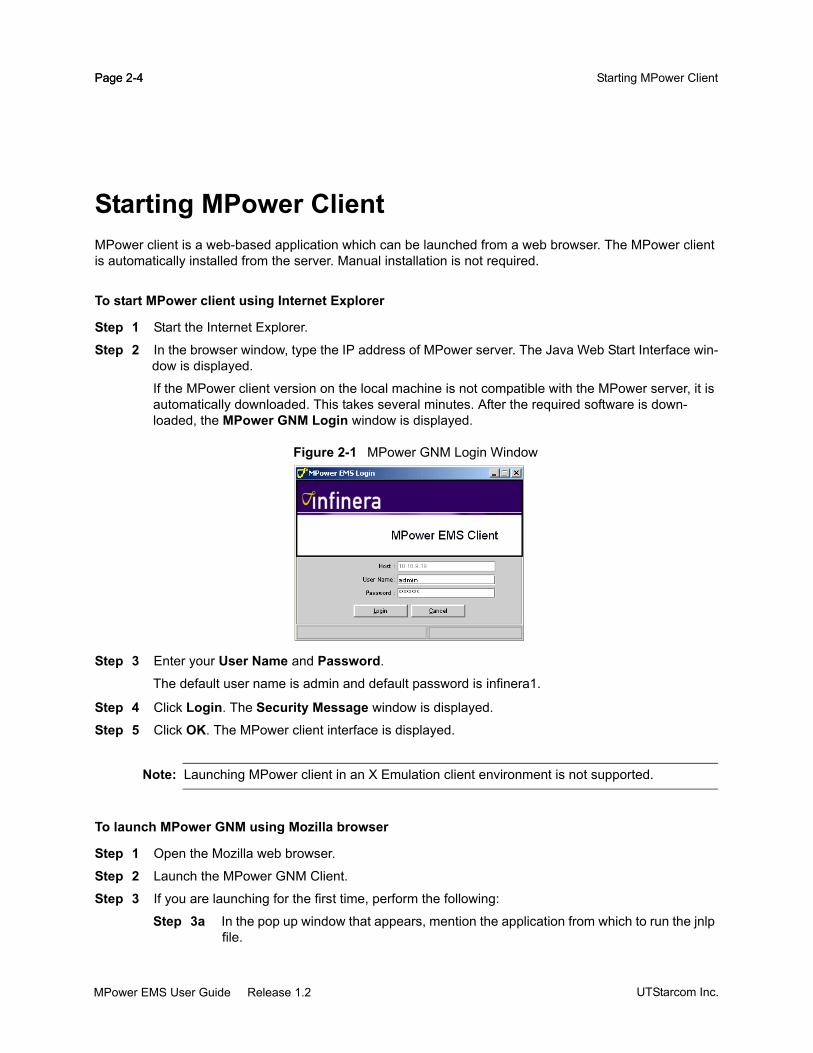
Page 2-4 Starting MPower ClientPage 2-4
Starting MPower ClientMPower client is a web-based application which can be launched from a web browser. The MPower client is automatically installed from the server. Manual installation is not required.
To start MPower client using Internet Explorer
Step 1 Start the Internet Explorer.
Step 2 In the browser window, type the IP address of MPower server. The Java Web Start Interface win-dow is displayed.
If the MPower client version on the local machine is not compatible with the MPower server, it is automatically downloaded. This takes several minutes. After the required software is down-loaded, the MPower GNM Login window is displayed.
Figure 2-1 MPower GNM Login Window
Step 3 Enter your User Name and Password.
The default user name is admin and default password is infinera1.
Step 4 Click Login. The Security Message window is displayed.
Step 5 Click OK. The MPower client interface is displayed.
Note: Launching MPower client in an X Emulation client environment is not supported.
To launch MPower GNM using Mozilla browser
Step 1 Open the Mozilla web browser.
Step 2 Launch the MPower GNM Client.
Step 3 If you are launching for the first time, perform the following:
Step 3a In the pop up window that appears, mention the application from which to run the jnlp file.
UTStarcom Inc.MPower EMS User Guide Release 1.2

Page 2-5Getting Started
Step 3b Mention the path of javaws application for running the above file.
Step 3c Save the settings to launch the MPower GNM Client.
MPower EMS User Guide Release 1.2UTStarcom Inc.

Page 2-6 Starting MPower ClientPage 2-6
UTStarcom Inc.MPower EMS User Guide Release 1.2

CHAPTER 3
Exploring the User Interface
The MPower GNM is an easy-to-use graphic user interface used to access the Digital Optical Network. The EMS interface provides context-sensitive navigation enabling applications to be accessed from one another. This chapter provides an overview of the EMS interface and provides information on how to use it. It contains:
“EMS Main View” on page 3-2
“Navigating through the MPower Client Interface” on page 3-13
“EMS GUI Conventions” on page 3-16
MPower EMS User Guide Release 1.2UTStarcom Inc.

Page 3-2 EMS Main ViewPage 3-2
EMS Main ViewOn a successful login to the EMS Client, the EMS Main View(Figure 3-1) is displayed. The EMS Main View displays a graphical representation of the network and provides access to the following:
Administrative domain(s) configured for the user
TN780 and Optical Line Amplifier network elements within the administrative domain
Network element user interfaces which include the network element’s chassis, circuit packs and ter-mination points
Figure 3-1 EMS Main View
The EMS Main View comprises of the following components as described in the following sections.
Workspace AreaThe Workspace Area is used to display the graphical representation of the network element/administrative domain being accessed and to launch other applications. The sections below describe the components/applications that can be viewed in the Workspace Area.
Equipment Tree
Main Menu
Quick ViewBrowser
Status Bar
Workspace Area
UTStarcom Inc.MPower EMS User Guide Release 1.2

Page 3-3Exploring the User Interface
Topology Graphical ViewThe Topology Graphical View is displayed when the MPower GNM is launched and displays all the administrative domains that the current user has access to. See UTStarcom MPower EMS Administrator Guide for more details.
Figure 3-2 Topology Graphical View
The Topology Graphical View displays the network with all network elements and control links in a graphical form. To view the network elements within the administrative domain, do one of the following:
Click the administrative domain name in the Equipment Tree.
Double click the administrative domain icon in the Topology Graphical View.
The Topology Graphical View displays the network components in two different views as described below.
Physical ViewThe Physical View displays all the TN780, Optical Line Amplifiers and control links configured for the selected administrative domain. By default, the Topology Graphic View area displays the world map as the background image with every network element represented using different icons (for network element type) and different colors (for status of the network element). See Table 3-4, “EMS Icon Schema,” on
MPower EMS User Guide Release 1.2UTStarcom Inc.

Page 3-4 EMS Main ViewPage 3-4
page 16 for node icons and color meaning. Selecting a node in the Physical View highlights it in the Equipment Tree and displays information summary about the network element in the Quick View Browser. The physical view can be saved to a file by clicking the Save/Edit Map button.
Figure 3-3 Physical View
Provisioning ViewThe Provisioning View displays all TN780s and control links configured for the selected administrative domain.
The Provisioning View allows you to provision the following services like:
Creation of cross-connects. See “Service Provisioning” on page 7-1 for procedures on how to create cross-connects.
Creation of circuits. See “Service Provisioning” on page 7-1 for procedures on how to create circuits.
The provisioning view can be saved to a file by clicking the Save/Edit Map button.
UTStarcom Inc.MPower EMS User Guide Release 1.2

Page 3-5Exploring the User Interface
Figure 3-4 Provisioning View
The Topology Graphical View provides short-cut menus to the most frequently performed operations as described below.
Inventory ToolsThe following inventory tools are supported:
Equipment Manager
The Equipment Manager displays an equipment inventory for the target network element in a tabular format. Filter operations allow users to customize how the information is displayed.
To view the Equipment Manager, do one of the following:
In the Provisioning View or Physical View, right-click the network element icon and select Tools >Equipment Manager.
In the Equipment Tree, right-click the network element icon and select Tools >Equipment Manager.
In the EMS Main Menu, select Configuration > Equipment Manager.
MPower EMS User Guide Release 1.2UTStarcom Inc.
Page 3-6 EMS Main ViewPage 3-6
Facility Manager
The Facility Manager displays all the available termination points. Filter operations allow users to customize how the information is displayed.
To view the Facility Manager, do one of the following:
In the Provisioning View or Physical View, right-click the network element icon and select Tools >Facility Manager.
In the Equipment Tree, right-click the network element icon and select Tools >Facility Man-ager.
In the EMS Main Menu, select Configuration > Facility Manager.
Cross-Connect ManagerThe Cross-Connect Manager is used to view, create, modify and delete manual cross-connects. For information on how to create cross-connects see “Service Provisioning” on page 7-1.
To view the Cross-Connect Manager, do one of the following:
In the Provisioning View or Physical View, right-click the network element icon and select Provision-ing >Cross-Connect Manager.
In the Equipment Tree, right-click the network element icon and select Provisioning >Cross-Con-nect Manager.
In the EMS Main Menu, select Provisioning >Cross-Connect Manager.
Circuit ManagerThe Circuit Manager is used to view, create, modify and delete circuits. For information on how to create circuits, see “Service Provisioning” on page 7-1.
To view the Circuit Manager, do one of the following:
In the Provisioning View or Physical View, right-click the network element icon and select Provision-ing >Circuit Manager.
In the Equipment Tree, right-click the network element icon and select Provisioning >Circuit Man-ager.
In the EMS Main Menu, select Provisioning >Circuit Manager.
Link ManagerThe Link Manager displays an inventory of the links with the source node and destination node in a tabular format. Filter operations allow users to customize how the information is displayed. The Link Manager allows you to search and export these details.
UTStarcom Inc.MPower EMS User Guide Release 1.2

Page 3-7Exploring the User Interface
To view the Link Manager:
In the EMS Main Menu, select Configuration > Link Manager.
In the Equipment Tree, right-click the network element icon and select Tools >Link Manager.
Node ManagerThe Node Manager displays a network element inventory for the selected administrative domain. Filter operations allow users to customize how the information is displayed.
To view the Node Manager, do one of the following:
In the Topology Graphical View, right-click the administrative domain icon and select Node Man-ager.
Chassis ViewThe Chassis View displays the target network element’s Main Chassis along with its contained equipment. To view the contents of another chassis, click on the corresponding chassis in the Equipment Tree. To select an item in Chassis View, left-click the desired item. The selected item is highlighted by a black outline. Selecting an item within the Chassis View refreshes the Equipment Browser (by highlighting the corresponding item in the tree structure) and the Quick View Browser (by displaying summary information about the newly selected item).
Right-clicking an item in the Equipment View displays a context-sensitive popup menu. The most frequently used actions are listed at the top of the menu, and the context sensitive actions appear after a separator. See “EMS GUI Conventions” on page 3-16 for a list of icons used in the MPower GNM interface.
Equipment TreeThe Equipment Tree provides a hierarchical view of all the administrative domains (and all network elements in the administrative domain) in the Digital Optical Network to which you have access. Refer MPower EMS Administrator Guide for information on administrative domain accessibility. When you select an item in the Equipment Tree, it is highlighted in the Topology Graphical View by black dots on the corners. When you right-click on an item, a context-sensitive popup menu is displayed. Depending on the access privilege of the user, some operations may be disabled, and appear in grey text.
The Equipment Tree displays the network element Label beside the icon by default. To display the network element name beside the icon, the tree option must be set. See “Configuring the Network Element Name and Label” on page 6-10 for more details.
Expanding the Equipment TreeThis section describes how to navigate through the Equipment Tree and the usage of the expand and collapse icons to improve the visibility of the physical equipment comprising the network.
MPower EMS User Guide Release 1.2UTStarcom Inc.

Page 3-8 EMS Main ViewPage 3-8
To expand the tree structure to show more levels of equipment:
Click the administrative domain name and click the button to expand the tree. Figure 3-5 Expanded Equipment Tree shows the expanded view of the tree.
Figure 3-5 Expanded Equipment Tree
Tree OptionFollow this procedure to invoke the Tree Option.
To invoke the Tree Option
Step 1 In the Main Menu, click Tools > Tree Options.
The Select Chassis View Tree Options window appears.
Step 2 Select the desired parameter and click Apply.
Step 3 Click Close to exit the Select Chassis View Tree Options window.
Find NodeFollow this procedure to find a node.
To find a node
Step 1 In the Main Menu, click Tools > Find Node.
The Find Network Element window appears.
Step 2 Enter the network element name in the Search String option.
Step 3 Click Find to find the network element.
Step 4 Click Close to exit the Find Network Element window.
UTStarcom Inc.MPower EMS User Guide Release 1.2

Page 3-9Exploring the User Interface
Network Information File EditorFollow this procedure to invoke the Network Information File Editor.
To invoke the Network Information File Editor
Step 1 In the Main Menu, click Tools > Network Information File Editor.The Network Information File Editor window appears.
Step 2 Click on a node to view the DCN IP Address, XML Port and Auto Discover status.
Step 3 Click Close to exit the Network Information File Editor window.
Quick View BrowserThe Quick View Browser provides a snapshot information about the equipment last selected in the EMS interface. The object can be the administrative domain, network element, chassis or circuit packs.
The Quick View Browser displays information on two panels:
Alarm Counts
The Alarm Counts panel summarizes the alarm count in the administrative domain. All alarms are indicated by a color for varying severities. Hyperlinks are provided to view the alarm summary based on the severity. The Alarm Manager opens in the Workspace area to display these alarms. See “Fault Management” on page 5-1 for more details on alarm categories and severities.
Figure 3-6 Alarm Count
Details
The Details Panel displays a textual summary of the equipment last selected in the EMS interface. The equipment can be administrative domain, network element, chassis or circuit pack.
MPower EMS User Guide Release 1.2UTStarcom Inc.
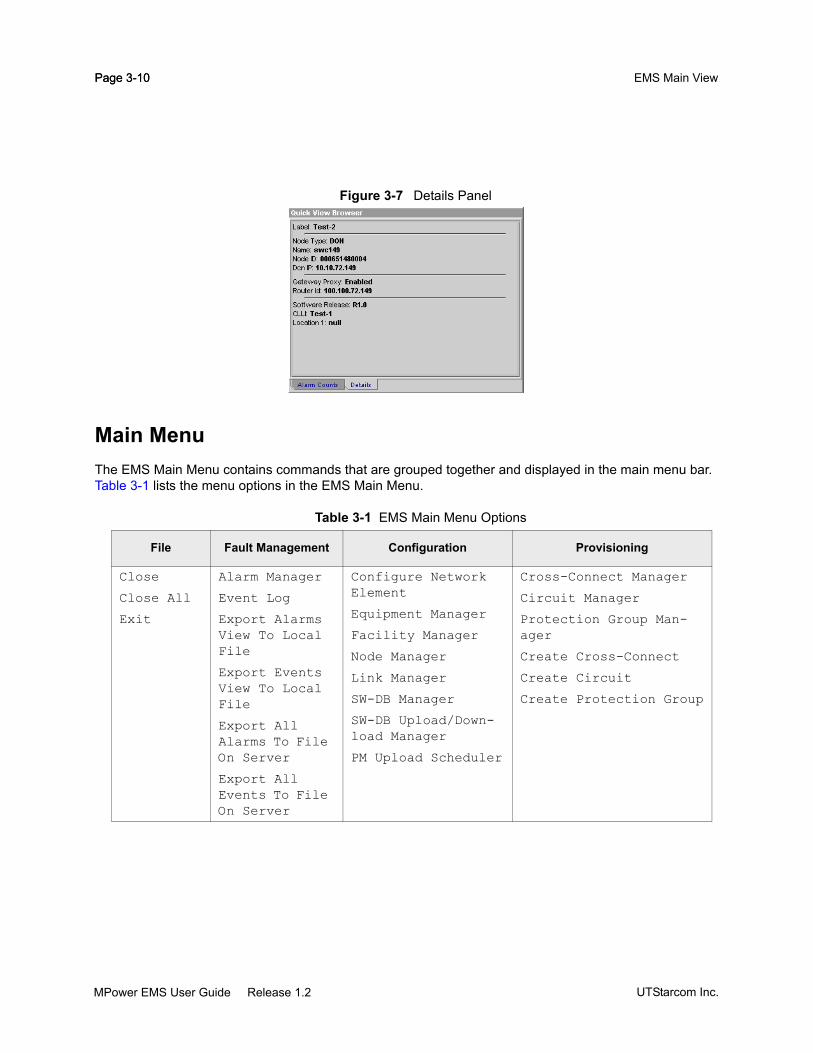
Page 3-10 EMS Main ViewPage 3-10
Figure 3-7 Details Panel
Main MenuThe EMS Main Menu contains commands that are grouped together and displayed in the main menu bar. Table 3-1 lists the menu options in the EMS Main Menu.
Table 3-1 EMS Main Menu Options
File Fault Management Configuration Provisioning
Close
Close All
Exit
Alarm Manager
Event Log
Export Alarms View To Local File
Export Events View To Local File
Export All Alarms To File On Server
Export All Events To File On Server
Configure Network Element
Equipment Manager
Facility Manager
Node Manager
Link Manager
SW-DB Manager
SW-DB Upload/Down-load Manager
PM Upload Scheduler
Cross-Connect Manager
Circuit Manager
Protection Group Man-ager
Create Cross-Connect
Create Circuit
Create Protection Group
UTStarcom Inc.MPower EMS User Guide Release 1.2

Page 3-11Exploring the User Interface
Keyboard AcceleratorsFrequently performed menu selections have keyboard accelerators. To access the menu options, select Alt+<underlined letter in the menu option>. For example, to access the Provisioning menu, hold the Alt key and press p. The Provisioning menu is dropped down.
ToolbarThe EMS Toolbar provides icons to operations performed on the view.
Security Performance Tools Window Help
Change Password
EMS Security Admin-istration
Active EMS Users
EMS Login Banner Setting
Configure Discov-ery Key Ring
Configure SNMP Man-ager (This is displayed only if the MPower SNMP Man-ager is installed)
PM Reports
PM Statis-tics By Node
Find Node
Tree Options
Network Informa-tion File Editor
Cascade
<NE Name>
Help Con-tents
About MPower GNM Client...
Table 3-2 Toolbar icons
Toolbar Icon Description
Displays the Provisioning View
Displays the Physical View
Zooms window
Saves or Edits the background map
Resets the map to the default layout
MPower EMS User Guide Release 1.2UTStarcom Inc.

Page 3-12 EMS Main ViewPage 3-12
Status BarThe Status Bar is located at the bottom of the EMS Main View. It displays the status of the last operation performed using the MPower GNM.
User Login IDThe User Login ID information is located at the bottom left corner of the screen. It displays the name of the current user.
UTStarcom Inc.MPower EMS User Guide Release 1.2

Page 3-13Exploring the User Interface
Navigating through the MPower Client InterfaceThe MPower client interface allows you to navigate within the interface enabling easy switching from one application to another. When you right-click an equipment, a network element icon, administrative domain icon or Digital Optical Network icon, menu options are displayed based on access privileges and applications that can be launched. The result of these operations depends on the selected item in the MPower client interface. This is called Context-Sensitive launch. Table 3-3 displays the navigation inside the MPower client interface.
Table 3-3 Navigating through the MPower Client Interface
Right-click Circuit Pack in the Equipment View or Equipment Tree of
the Chassis View
Right-click Network Element in the Equipment
Tree or Topology Graphical View
Right-click Administrative Domain in
the Equipment Tree or Topology Graphical View
Right-click UTStarcom Network
in the Topology Graphical View
Alarm Manager
To view all alarms raised by the circuit pack:- Choose Show Alarms
To view all alarms raised by the network element:- Choose Show Alarms
To view all alarms raised by all the network elements within the selected administrative domain:- Choose Show Alarms
To view all alarms raised by all administrative domains you have access to:- Choose Alarm Manager
Event Log
Not available To view all events raised by the network element:- Choose Show Events
To view all events raised by all the network elements within the selected administrative domain:- Choose Show Events
To view all events raised by all administrative domains you have access to:- Choose Event Log
Circuit Manager
To view all circuits that have the selected circuit pack as one of the end points:- Choose Provisioning > Circuit Manager
To view all circuits that have the network element as one of the end points:- Choose Provisioning > Circuit Manager
To view and manage all circuits within the selected administrative domain:- Choose Provisioning > Circuit Manager
To view and manage all circuits within the administrative domains you have access to:- Choose Provisioning > Circuit Manager
Cross-Connect Manager
To view all cross-connects that have the selected circuit pack as one of the end points:- Choose Cross-Connect Manager
To view all cross-connects that have the network element as one of the end points:- Choose Cross-Connect Manager
To view and manage all cross-connects within the selected administrative domain:- Choose Provisioning > Cross-Connect Manager
To view and manage all cross-connects within the administrative domains you have access to:- Choose Provisioning > Cross-Connect Manager
Protection Group Manager
To view all protection groups that have the circuit pack as one of the node that it traverses:- Right-click TOM and choose Protection Group Manager
To view all protection groups that have the network element as one of the node that it traverses:- Choose Provisioning > Protection Group Manager
To view all protection groups within the selected administrative domain:- Choose Provisioning > Protection Group Manager
To view all protection groups within the administrative domains you have access to:- Choose Provisioning > Protection Group Manager
Equipment Manager
MPower EMS User Guide Release 1.2UTStarcom Inc.

Page 3-14 Navigating through the MPower Client InterfacePage 3-14
Not applicable To view all equipment configured for the selected network element:- Choose Tools >Equipment Manager
To view and manage all equipment configured within the selected administrative domain:- Choose Tools > Equipment Manager
To view and manage all equipment configured within the administrative domains you have access to:- Choose Tools > Equipment Manager
Facility Manager
Not available To view all facilities configured for the selected network element:- Choose Tools >Facility Manager
To view and manage all facilities configured within the selected administrative domain:- Choose Tools > Facility Manager
To view and manage all facilities within the administrative domains you have access to:- Choose Tools > Facility Manager
Node Manager
Not applicable Not applicable To view all nodes within the selected administrative domain- Choose Node Manager
To view all nodes within the administrative domains you have access to:- Choose Node Manager
View Performance Monitoring Reports
Not available To view performance monitoring reports for the network element:In the EMS Main Menu, select Performance > PM Reports
Not available Not available
Security Administration
Not applicable To perform network element security administration:- Choose Tools >Admin > NE Security Administration
Not available Not available
Software and Database Configuration Manager
Not applicable To perform software and database upload and download operations on a network element:- Choose Tools > Admin > SW-DB Upload/Download Manager orTools > Admin > SW-DB Manager
To perform software and database upload and download operations on any of the network elements within the selected administrative domain:- Choose Tools > Admin > SW-DB Upload/Download Manager orTools > Admin > SW-DB Image Manager
To perform software and database upload and download operations on any of the network elements within the administrative domains you have access to:- Choose Tools > Admin > SW-DB Upload/Download Manager orTools > Admin > SW-DB Image Manager
Launch TL1 Session
Not applicable To launch TL1 session on the selected network element:- Choose Tools >TL1 Session
Not applicable Not applicable
Network Information File Editor
Not applicable To view Network Information File Editor:- Choose Tools > Network Information File Editor
Not applicable Not applicable
Table 3-3 Navigating through the MPower Client Interface
Right-click Circuit Pack in the Equipment View or Equipment Tree of
the Chassis View
Right-click Network Element in the Equipment
Tree or Topology Graphical View
Right-click Administrative Domain in
the Equipment Tree or Topology Graphical View
Right-click UTStarcom Network
in the Topology Graphical View
UTStarcom Inc.MPower EMS User Guide Release 1.2

Page 3-15Exploring the User Interface
SNMP Manager
Not applicable To launch MPower SNMP Manager:- Choose Tools > Configure SNMP Manager
Not applicable Not applicable
Table 3-3 Navigating through the MPower Client Interface
Right-click Circuit Pack in the Equipment View or Equipment Tree of
the Chassis View
Right-click Network Element in the Equipment
Tree or Topology Graphical View
Right-click Administrative Domain in
the Equipment Tree or Topology Graphical View
Right-click UTStarcom Network
in the Topology Graphical View
MPower EMS User Guide Release 1.2UTStarcom Inc.

Page 3-16 EMS GUI ConventionsPage 3-16
EMS GUI ConventionsThe EMS uses specific icons and color-coding to represent equipment and their corresponding status as described in Table 3-4. The EMS Node schema is as described in Table 3-5. The EMS Link schema is as described in Table 3-6.
Table 3-4 EMS Icon Schema
Icon Icon Name Description
Equipment Tree Administra-tive Domain
Administrative Domain as displayed in the Equipment Tree.
Provisioning and Physical View Administrative Domain
Administrative Domain as displayed in the Provisioning and Physical View.
Equipment Tree Digital Add-Drop network element
The Add-Drop network element as displayed in the Equip-ment Tree.
Equipment Tree Digital Repeater network element
The Digital Repeater network element as displayed in the Equipment Tree.
Equipment Tree Optical Line Amplifier network element
The Optical Line Amplifier as displayed in the Equipment Tree.
Equipment Tree Digital Optical Node
The Digital Optical Node as displayed in the Equipment Tree.
Equipment Tree Digital Termi-nal
The Digital Terminal as displayed in the Equipment Tree.
Physical and Provisioning View Digital Add-Drop network element
The Add-Drop network element as displayed in the Physi-cal and Provisioning Views.
Physical and Provisioning View Digital Repeater net-work element
The Digital Amplifier as displayed in the Physical and Pro-visioning Views.
Physical View Optical Line Amplifier network element
The Optical Line Amplifier as displayed in the Physical View.
Physical and Provisioning View Digital Optical Node
The Digital Optical Node as displayed in the Physical and Provisioning Views.
UTStarcom Inc.MPower EMS User Guide Release 1.2

Page 3-17Exploring the User Interface
Physical and Provisioning View Digital Terminal network element
The Digital Terminal as displayed in the Physical and Pro-visioning Views.
Critical Alarm Circuit Pack Indicates a circuit pack with at least one outstanding alarm of critical severity level. The Equipment View displays the card in red.
Major Alarm Circuit Pack Indicates a circuit pack with at least one outstanding alarm of major severity level. The Equipment View displays the card in orange.
Minor Alarm Circuit Pack Indicates a circuit pack with at least one outstanding alarm of minor severity level. The Equipment View displays the card in yellow.
Warning Circuit Pack Indicates a circuit pack with at least one warning. The Equipment View displays the card in cyan.
No Alarm Circuit Pack Indicates a circuit pack with no outstanding alarms. The icon is positioned next to the equipment number in the Equipment Tree.
Critical Alarm Chassis Indicates a chassis with at least one critical outstanding alarm. The icon is positioned next to the chassis ID in the Equipment Tree.
Major Alarm Chassis Indicates a chassis with at least one major outstanding alarm. The icon is positioned next to the chassis ID in the Equipment Tree.
Minor Alarm Chassis Indicates a chassis with at least one minor outstanding alarm. The icon is positioned next to the chassis ID in the Equipment Tree.
Warning Chassis Indicates a chassis with at least one warning. The icon is positioned next to the chassis ID in the Equipment Tree.
No Alarm Chassis Indicates a chassis with no outstanding alarms. The icon is positioned next to the chassis ID in the Equipment Tree.
Critical Alarm PEM Indicates a Power Entry Module with at least one critical outstanding alarm. The icon is positioned in the top left cor-ner of the Equipment View.
Major Alarm PEM Indicates a Power Entry Module with at least one major outstanding alarm. The icon is positioned in the top left cor-ner of the Equipment View.
Minor Alarm PEM Indicates a Power Entry Module with at least one minor outstanding alarm. The icon is positioned in the top left cor-ner of the Equipment View.
Table 3-4 EMS Icon Schema
Icon Icon Name Description
MPower EMS User Guide Release 1.2UTStarcom Inc.

Page 3-18 EMS GUI ConventionsPage 3-18
Warning PEM Indicates a Power Entry Module with at least one warning. The icon is displayed in the top left corner of the Equipment View.
No Alarm PEM Indicates a Power Entry Module with no alarms. The icon is positioned in the top left hand corner of the Equipment View.
Critical Alarm FAN Indicates a fan with at least one critical outstanding alarm. The icon is positioned in the top left hand corner of the Equipment View beside the Power Entry Module icons.
Major Alarm FAN Indicates a fan with at least one major outstanding alarm. The icon is positioned in the top left hand corner of the Equipment View beside the Power Entry Module icons.
No Alarm FAN Indicates a fan with no outstanding alarms. The icon is positioned in the top left hand corner of the Equipment View beside the Power Entry Module icons.
Equipment Under Mainte-nance
Indicates that the equipment is under maintenance and will not provide any service.
Equipment Unlocked Indicates that the equipment is in an unlocked state. All outstanding alarms are re-evaluated and new alarms are raised appropriately.
Equipment Locked Indicates that the equipment is in a locked state. All out-standing alarms on the equipment are cleared, and new alarm reporting is suppressed.
Equipment Alarm Reporting Enabled
Indicates that alarm reporting for the equipment is enabled.
Equipment Alarm Reporting Disabled
Indicates that alarm reporting for the equipment and its daughter cards are disabled.
Equipment Alarm Reporting Inhibited
Indicates that alarm reporting for the equipment is inhib-ited. No alarms will be reported for this equipment.
Parent Equipment Alarm Reporting Disabled
Indicates that alarm reporting for the equipment is disabled because it is disabled for the parent object.
Parent and This Equipment Alarm Reporting Disabled
Indicates that alarm reporting for the equipment and the parent object is disabled.
Equipment Out of Service and Maintenance
Indicates that the equipment is out-of-service and in administrative maintenance state.
Table 3-4 EMS Icon Schema
Icon Icon Name Description
UTStarcom Inc.MPower EMS User Guide Release 1.2

Page 3-19Exploring the User Interface
Equipment Out of Service and Locked
Indicates that the equipment is out-of-service and in administrative locked state.
Empty Circuit Pack Indicates an empty circuit pack, that is, one that does not contain any plug-in modules such as a tributary adaptor module (TAM) or tributary optical module (TOM).
Empty Slot Indicates an empty slot in the chassis.
Table 3-5 EMS Node Schema
Node Color Description
Indicates a critical alarm on the node.
Indicates a major alarm on the node.
Indicates a minor alarm on the node.
Indicates a warning on the node.
Indicates an unreachable alarm on the node.
Indicates that the node is being discovered.
Indicates that the node is out of synch.
Indicates that the node has no alarm.
Table 3-4 EMS Icon Schema
Icon Icon Name Description
MPower EMS User Guide Release 1.2UTStarcom Inc.

Page 3-20 EMS GUI ConventionsPage 3-20
Table 3-6 EMS Link Schema
Link Color Description
Indicates that the aggregation of alarms on the termination points contained by the link is critical.
Indicates that the aggregation of alarms on the termination points contained by the link is major.
Indicates that the aggregation of alarms on the termination points contained by the link is minor.
Indicates that the aggregation of alarms on the termination points contained by the link is a warning.
Indicates that the control links contained by the link have failed. This appears only in the physical view. Click the link to view the last known information about the link, in the Quick View Browser.
Indicates that the aggregation of alarms on the termination points contained by the link is null.
UTStarcom Inc.MPower EMS User Guide Release 1.2

CHAPTER 4
Fault Management
This chapter describes the Fault Management applications provided by the TN780 and the Optical Line Amplifier network elements (referred to as network element) in the following sections:
“Overview” on page 4-2
“Alarm Monitoring” on page 4-4
“Event Management” on page 4-15
MPower EMS User Guide Release 1.2UTStarcom Inc.

Page 4-2 OverviewPage 4-2
OverviewThe fault monitoring and management capabilities of Digital Optical Networks are modeled after Telcordia and ITU standards. For a detailed description of these capabilities, refer to the UTStarcom TN780 System Description manual.
MPower GNM allows you to:
monitor alarms and events detected by the network or the external sensors connected to it.
retrieve alarms and events stored in the network element.
assign alarm severity through the Alarm Severity Assignment Profile (ASAP) application.
inhibit (and allow) alarm reporting on a per-managed-entity basis.
MPower GNM provides a central location for monitoring critical events and alarms generated by the target network element. The area of fault management covers all operations and functionality pertaining to the reporting and testing of conditions in the target network element. Digital Optical Networks support two types of notifications, namely alarms and events. Figure 4-1 summarizes the different types of alarms and events.
Figure 4-1 Events and Notifications
AlarmsAn alarm is an indication of a failure condition. Alarms are assigned severities as critical, major, minor and warning, depending on the degree of service degradation or disruption.
EventsEvents identify changes to an entity in the network. Events indicate that some operation was performed through MPower GNM. Events are recorded within the system and are available to management
Notifications
Alarms Events
AlarmedConditions
ThresholdCrossing
Conditions
Non-AlarmedConditions
AdministrativeEvents
Threshold CrossingEvents
Security Events Audit Events
UTStarcom Inc.MPower EMS User Guide Release 1.2

Page 4-3Fault Management
applications for data-model synchronization and reporting. Events are stored and can be viewed in the Event Log.
Network elements recognize the following types of notifications:
Conditions
Conditions are reported when anything other than the usual behavior of the managed network ele-ment occurs. Conditions are further divided into the following categories:
Alarmed conditions—Conditions that require immediate action are reported as alarms. These conditions require immediate attention, for example Loss of Light. They are differentiated by the severity. These events are also available in the alarm list.
Non-alarmed conditions—Conditions that are mostly informational are reported as non-alarmed conditions. For example, a port in loopback.
Threshold crossing conditions—These conditions are reported when there is a threshold crossing.
Reporting Events
Reporting events are generated by the target network element when there is a state change in the managed network element. Reporting events are divided into the following categories:
Security event—Events generated when there are security violations in the managed network element.
Administrative event—Events reported when there is an administrative-related action such as the modification of the user account details.
Threshold crossing event—Events that report threshold crossing information.
Audit event—Records of user actions that modify the state of any of the managed objects within the network element.
MPower GNM provides the following two tools to view alarms and events generated in the network:
Alarm Manager
Event Log
These tools are useful for the following operations:
Displaying detailed information about events and alarms
Sorting and filtering alarms into categories
Dynamically updating the alarms and events lists in multiple ways to make the information more useful; for example, changing the color of the card when an alarm is reported
Acknowledging alarms by including custom information (acknowledge text)
Launching applicable context sensitive tools like Facility Manager and Equipment Manager for the selected alarm or event
MPower EMS User Guide Release 1.2UTStarcom Inc.

Page 4-4 Alarm MonitoringPage 4-4
Alarm MonitoringThis section describes the various components of the Alarm Manager and provides detailed procedures for using it, under the following sections:
“Alarm Manager” on page 4-4
“Using the Alarm Manager” on page 4-6
Alarm ManagerThe Alarm Manager displays all outstanding conditions (alarms) in a tabular form. All outstanding alarms are maintained in the Alarm Table and displayed until the condition is cleared. The Alarm Manager is displayed by default on GNM startup and is re-sizeable. The Alarm Manager is at the bottom right of the GNM Main View and is visible as long as GNM is running.
Note: Re-ordering of columns remain in effect only for the current session.
The Alarm Manager allows you to:
view alarm details.
sort fields.
filter alarms based on alarm type and/or severity. For example, combine filtering all Equipment alarms with severity as major.
add additional text to an alarm.
launch applicable context-sensitive tools like Facility Manager for the selected alarm.
Figure 4-2 Alarm Manager
The Alarm Manager consists of the following panels:
Alarm Summary Panel
Alarm Table
Severity Filtering panel
Maximize or Minimize the Alarm Manager
Hide Filter panel
Alarm Filter panel
Alarm Filtered Count panel
UTStarcom Inc.MPower EMS User Guide Release 1.2
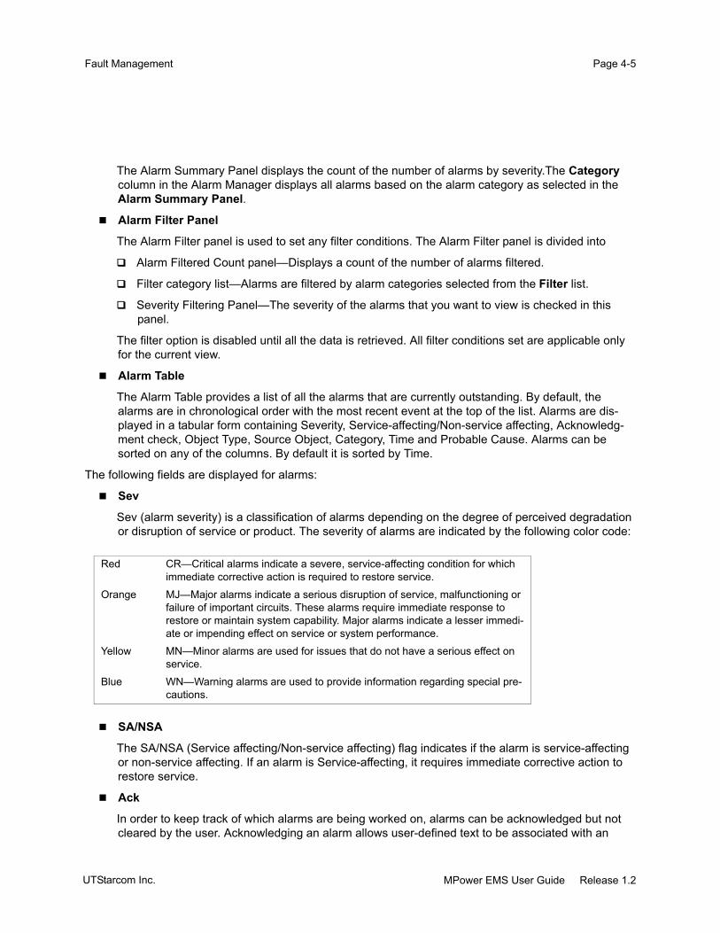
Page 4-5Fault Management
The Alarm Summary Panel displays the count of the number of alarms by severity.The Category column in the Alarm Manager displays all alarms based on the alarm category as selected in the Alarm Summary Panel.
Alarm Filter Panel
The Alarm Filter panel is used to set any filter conditions. The Alarm Filter panel is divided into
Alarm Filtered Count panel—Displays a count of the number of alarms filtered.
Filter category list—Alarms are filtered by alarm categories selected from the Filter list.
Severity Filtering Panel—The severity of the alarms that you want to view is checked in this panel.
The filter option is disabled until all the data is retrieved. All filter conditions set are applicable only for the current view.
Alarm Table
The Alarm Table provides a list of all the alarms that are currently outstanding. By default, the alarms are in chronological order with the most recent event at the top of the list. Alarms are dis-played in a tabular form containing Severity, Service-affecting/Non-service affecting, Acknowledg-ment check, Object Type, Source Object, Category, Time and Probable Cause. Alarms can be sorted on any of the columns. By default it is sorted by Time.
The following fields are displayed for alarms:
Sev
Sev (alarm severity) is a classification of alarms depending on the degree of perceived degradation or disruption of service or product. The severity of alarms are indicated by the following color code:
SA/NSA
The SA/NSA (Service affecting/Non-service affecting) flag indicates if the alarm is service-affecting or non-service affecting. If an alarm is Service-affecting, it requires immediate corrective action to restore service.
Ack
In order to keep track of which alarms are being worked on, alarms can be acknowledged but not cleared by the user. Acknowledging an alarm allows user-defined text to be associated with an
Red CR—Critical alarms indicate a severe, service-affecting condition for which immediate corrective action is required to restore service.
Orange MJ—Major alarms indicate a serious disruption of service, malfunctioning or failure of important circuits. These alarms require immediate response to restore or maintain system capability. Major alarms indicate a lesser immedi-ate or impending effect on service or system performance.
Yellow MN—Minor alarms are used for issues that do not have a serious effect on service.
Blue WN—Warning alarms are used to provide information regarding special pre-cautions.
MPower EMS User Guide Release 1.2UTStarcom Inc.

Page 4-6 Alarm MonitoringPage 4-6
alarm. Everyone who has access to the Alarm Manager sees this change. An alarm can be re-acknowledged at a later point if the need arises.
Object Type
The object type specifies the object to which this alarm is associated.
Object Name
The source object specifies the name of the object on which the alarm has been raised, for example, PEM.
Category
Every alarm belongs to a category. The alarm categories available are listed in Table 4-1.
Time
The time indicates the time at which the alarm was raised by the network element. The time is always shown in UTC.
Probable Cause
The probable cause is the most likely reason for the occurrence of an alarm, for example, bandwidth reduced. For more details on the various probable causes, refer to the UTStarcom TN780 and Opti-cal Line Amplifier Maintenance and Troubleshooting Guide.
Using the Alarm ManagerThe following tasks can be performed on the Alarm Manager:
“Viewing Alarm Details” on page 4-7
Table 4-1 Alarm Categories
Alarm Category Description Example
Communication Alarms Is associated with faults which impact the com-munication between the modules within the net-work element and between network elements.
Loss of Light
Quality of Service Alarms Is associated with the degradation in the quality of a service.
Response time excessive
Environmental Alarms Is associated with the change in the state of the environmental alarm input contact.
Temperature unacceptable
Equipment Alarms Is associated with the hardware faults. Dataset or modem error
Facility Alarms Is associated with a termination point fault, the line and tributary facilities, and incoming signal.
DTS Trace mismatch
Software Processing Alarms
Is associated with a software or processing fault. Version mismatch
None Indicates that no filter has been set and displays all alarms.
UTStarcom Inc.MPower EMS User Guide Release 1.2

Page 4-7Fault Management
“Acknowledging Alarms” on page 4-9
“Inhibiting Alarms” on page 4-9
“Exporting Alarms” on page 4-10
“Filtering Alarm Data” on page 4-10
“Sorting Alarm Data” on page 4-11
“Resizing Column Width” on page 4-12
“Hiding and Displaying the Filter Panel” on page 4-12
“Maximizing/Minimizing the Alarm Manager” on page 4-12
Viewing Alarm DetailsAlarm details are viewed from the Alarm Properties window.
To view the details of an alarm
Step 1 In the Alarm Manager, double-click the alarm for which you would like to view the details.
The Alarm Details window is displayed.
MPower EMS User Guide Release 1.2UTStarcom Inc.

Page 4-8 Alarm MonitoringPage 4-8
Figure 4-3 Alarm Properties
Table 4-2 Alarm Properties
Item Description
SummarySource Name The name of the object associated with the alarm.
Service Affecting A flag indicating if the alarm can result in a loss of service.
Severity The severity of the alarm. Can be critical, major, minor, warning, unreach-able.
Date The date and time when the alarm was raised.
Alarm Category The alarm category. See Table 4-1 on page 4-6 for the alarm categories.
Node Name The name of the network element that raised the alarm.
Node Label Unique identifier for the node.
Probable Cause Description
The most likely reason for the occurrence of an alarm. For example, Loss of Light.
ParametersAlarm ID Unique identifier that specifies the alarm.
Correlation ID A system-generated ID that specifies the correlation identifier.
Direction The direction from which the alarm has been received. The direction can be Transmit, Receive or DirNA.
Probable Cause A brief description of the most likely reason for the occurrence of the alarm.
Event Type The type of event. The type can be a Condition or Report.
Event SubType The subtype of the event. This varies based on the event type. The sub-type can be alarm or TCC.
UTStarcom Inc.MPower EMS User Guide Release 1.2

Page 4-9Fault Management
Acknowledging AlarmsAn alarm is acknowledged to associate text to the alarm.
To acknowledge alarms
Step 1 In the Alarm Manager, right-click the alarm you want to acknowledge. The Alarm Acknowl-edgement window is displayed.
Step 2 Enter the acknowledge text in the Acknowledged Text field.
Step 3 Click Acknowledge to save the changes.
The user ID of the acknowledging user is displayed in the Ack column of the Alarm Manager.
Figure 4-4 Acknowledging an alarm
Inhibiting AlarmsInhibition refers to the suppression of alarm generation and is used to silence a managed entity that is active, but which is being serviced or is awaiting valid signal flow. A typical example is a drop-side port in
Location The location of the network element from which the alarm has been raised.
Acknowledgement InformationUser The login name of the user responsible for this acknowledgment.
Time The time at which the alarm was acknowledged.
Acknowledged TextAcknowledgement Text User entered comments about the acknowledgment.
Additional TextAdditional Text Additional details about the alarm.
Table 4-2 Alarm Properties
Item Description
MPower EMS User Guide Release 1.2UTStarcom Inc.

Page 4-10 Alarm MonitoringPage 4-10
Administrative in-service (AINS) state that is awaiting interconnection to the customer premises equipment (CPE). In such cases, operations staff would like the alarms inhibited on this resource, as it is not yet providing live service. Although the resource may be detecting alarms such as Loss Of Signal, these should not be recorded in the Alarm Manager, transmitted to any client, or displayed in the system's active alarm list.
To inhibit alarms
Step 1 In the GNM Main View, select the equipment for which alarms are to be inhibited.
Step 2 Right-click and select Alarm Reporting > Disable.
Note: Only users with Network Engineer and Network Administrator privileges can inhibit alarms.
Exporting AlarmsAll outstanding alarms displayed in the Alarm Manager can be exported to a tab separated value (TSV) file. The export operation only captures the alarms in the current page. This file can be viewed using any standard text editor like vi or Notepad.
To export alarm details
Step 1 In the Equipment View, select Fault Management > Export Current View of Alarms To File to save all the currently displayed alarms. The Save dialog box is displayed.
In the Equipment View, select Fault Management > Export All Alarms To File to save all the alarms on the server. The Save dialog box is displayed.
Step 2 Navigate to the directory location where you would like to save the alarm information.
Step 3 Enter the name of the file and click Save.
The alarm information is now saved.
Filtering Alarm DataFilter conditions can be applied on alarm lists in the Alarm Manager. The sophisticated filter options allow finer granularity in viewing specific outstanding alarms. Filtering conditions are set by selecting the alarm category or severity. They can be used individually or in combination.
Note: All filtering conditions are applied to the alarms displayed in the current page.
To filter alarms
Step 1 In the Alarm Filter panel, select the alarm type from the Filter list.
UTStarcom Inc.MPower EMS User Guide Release 1.2

Page 4-11Fault Management
Step 2 Select the alarm severity checkbox(s).
Step 3
Figure 4-5 Filter Panel
The Filter panel displays the fields as listed below:
Sorting Alarm DataThe data displayed in the current view of the Alarm Manager can be sorted by all fields in both ascending and descending order. Sorting is applied according to the following rules:
Numbers are sorted in numeric sequence.
Text is sorted by ASCII sequence.
To sort data in tables
Step 1 Click any column heading to sort the data in ascending order. The sort order is identified by a tri-angle pointing in the direction of sort. To reverse the sort order, click the column header again.
Table 4-3 Filter Panel
Item Description
Filtered Count Specifies a count of the number of alarms filtered.
Filter drop-down menu Lists the alarm types or the connection type based on which alarms will be fil-tered.
Severity The severity of alarms that will be filtered. Only alarms with severity checked are displayed.
Hide and unhide the Filter panelFilter for Communication alarms
MPower EMS User Guide Release 1.2UTStarcom Inc.

Page 4-12 Alarm MonitoringPage 4-12
Figure 4-6 Sort Order
Resizing Column Width
To change the width of the column
Step 1 Move the cursor to the column separator (the vertical line) on the right side of the column. The cursor changes to a horizontal double-arrow.
Step 2 Click and hold while moving the mouse either left or right to adjust the column width. All columns to the right are moved to accommodate the new column width.
Hiding and Displaying the Filter PanelThe filter panel can be hidden and subsequently be displayed. The hide/unhide button is in the vertical position when the Filter panel is displayed (see Figure 4-8). This is possible by using the hide and unhide button.
To hide the Filter panel
Step 1 Click the hide/unhide button.
When the Filter Panel is hidden, the hide/unhide button is in a horizontal position.
Maximizing/Minimizing the Alarm ManagerThe Alarm Manager can be maximized or minimized from the position in which it is currently displayed. Use the maximize or minimize button provided at the top left corner of the Alarm Manager. The direction of the arrow indicates whether the Alarm Manager will be minimized or maximized.
To maximize the Alarm Manager
Step 1 Click the Maximize button once. The Alarm Manager is maximized relative to the position it is currently displayed. For example,
If the Alarm Manager is in the normal position, it is maximized and displayed in the entire Workspace Area.
Alarms are sorted by Object Name
UTStarcom Inc.MPower EMS User Guide Release 1.2

Page 4-13Fault Management
If the Alarm Manager is minimized completely, clicking the Maximize button restores it to the normal position.
To restore the Alarm Manager
Do one of the following:
Click the maximize button above the Alarm Filter panel.
In the GNM Main View, select Fault Management > Alarm Manager or
Figure 4-7 Maximizing/Minimizing Alarm Manager
Alarm Severity Assignment ProfileAll alarms generated are assigned a factory-set default severity and service affecting value. The factory-default values can be edited using the Alarm Severity Assignment Profile (ASAP) feature.
The ASAP feature can be used to customize the following attributes:
Severity—Specifies the new alarm severity assigned to the alarm.
Affects Chassis LED—Indicates if the chassis level LED is affected when the alarm is raised.
ASAP is edited from the Alarm Severity Assignment Profile Settings window.
To edit the Alarm Severity Assignment Profile
Step 1 In the GNM Main View, select Fault Management > Alarm Severity Profile Settings. The Alarm Severity Assignment Profile Settings window is displayed.
Step 2 Select an alarm object. The attributes are displayed in the Profile Attributes panel.
Step 3 Select the new severity from the Severity list.
Step 4 Select Affects Chassis LED checkbox if the LED should be lit when the alarm is raised. Other-wise, leave the checkbox blank.
Step 5 To save your changes, click Apply.
Step 6 When you are done, click Close to exit the Alarm Severity Assignment Profile Settings window.
Maximize button
Minimize button
MPower EMS User Guide Release 1.2UTStarcom Inc.

Page 4-14 Alarm MonitoringPage 4-14
Figure 4-8 Alarm Severity Assignment Profile
The Alarm Severity Assignment Profile Settings window is divided into the following sections as described below.
Profile Table—The Profile Table lists the factory set attributes as listed in Table 4-4.
Profile Attributes—Attributes of the alarm selected in the Profile Table.
Table 4-4 Alarm Severity Assignment Profile:Profile Attributes
Item Description
Applies to Object The equipment that raised the alarm.
Probable Cause The most likely reason for the occurrence of an alarm.
Category The alarm category. See Table 4-1 for the alarm categories.
Severity The alarm severity. Alarm severity can be one of critical, major, minor or warning.
Type Parameter that indicates if the alarm affects service. This field is read only can be Service Affecting or Non-Service Affecting.
Affects Chassis LED Parameter that indicates if the chassis level LED will be illuminated when this alarm is raised.
Profile Table
Profile Attributes
UTStarcom Inc.MPower EMS User Guide Release 1.2

Page 4-15Fault Management
Event ManagementThis section describes the various components of the Event Manager (See “Event Log” on page 4-15) and provides detailed procedures to use it (See “Using the Event Log” on page 4-17).
Event LogThe Event Log displays a list of all events in a tabular form. The events displayed in this browser are generated by the network element.
To launch the Event Log
Step 1 From the GNM Main Menu, select Fault Management > Event Log.
The Event Log window is displayed.
Figure 4-9 Event Log
The Event Log has the following panels:
Event Summary Log
MPower EMS User Guide Release 1.2UTStarcom Inc.

Page 4-16 Event ManagementPage 4-16
The Event Summary Log provides a summary of the total number of events that were generated by the managed network element (Total) and the count of the number of events that have been filtered (Filtered Count).
Event Filter Panel
The Event Filter panel is used to set filter conditions. Events are filtered by event types selected from the Filter drop-down menu. Events can be filtered by severity in combination with event types or independently. All filter conditions set are applicable only for the current view, that is, filtering choices selected in one instance does not affect Event Log lists being viewed by other users.
Event Table
The Event Table provides a tabular list of events raised by the network element. By default, the events are in chronological order with the most recent event at the top of the list. The event list is dis-played with the following fields: Severity, Node Id, Node Name, Node Label, Source Object, Object Type, Event Type, Event Sub Type, Date/Time, Message, and Changed Variables.The column width can be resized and the order of fields displayed can be rearranged for conve-nience. See “Sorting Alarm Data” on page 4-11 and “Resizing Column Width” on page 4-12 for detailed procedures.
Pause Button
Clicking the Pause Button stops the event log from getting updated on the screen. To resume upda-tion of the event log on the screen, click the Pause Button once again.
Following is the description of the attributes reported for each event.
Severity
The severity of an event provides an indication of how the capability of the component affected is perceived. Severity levels are represented from most severe to least severe as Critical, Major, Minor, Warning, Clear, Information, and Unreachable.The severity of alarms are indicated by a color code for easy differentiation between important alarms and information alarms. By default, alarms are indicated by the colors as listed below.
Source Object
The source object is an equipment identifier that indicates where the event was generated. For example, if the event is generated from PEM 1, the source object is displayed as 1-IOSHELF-PEM1.
Red CR—Critical alarms indicate a severe, service-affecting condition for which immediate corrective action is required to restore service.
Orange MJ—Major alarms indicate a serious disruption of service, malfunctioning or failure of important circuits. These alarms require immediate response to restore or maintain system capability. Major alarms indicate a lesser immedi-ate or impending effect on service or system performance.
Yellow MN—Minor alarms are used for issues that do not have a serious effect on service to customers.
Blue WN—Warning alarms that are used to provide information regarding special precautions.
Grey Info—Information on the events that are raised.
UTStarcom Inc.MPower EMS User Guide Release 1.2

Page 4-17Fault Management
Object Type
The object type specifies the type of equipment that initiated the alarm. For example, if the event is a power failure, the object type is displayed as PEM.
Event Type
The Event type displays the event type based on the action performed. See “Events” on page 4-2 for a list of event types.
Event Sub Type
The Event subtype displays the event sub type based on the action performed. See “Events” on page 4-2 for a list of event sub types.
Time
The Time column displays the date and time in GMT at which the event was raised.
Message
The Message column displays additional information about the event that briefly describes the cause of the event.
Changed Variables
The Changed Variables column displays the attribute(s) that changed and the new value(s).
Using the Event LogThe following tasks can be performed on the event log:
“Viewing Event Details” on page 4-17
“Exporting Event Details” on page 4-19
“Filtering Event Data” on page 4-19
“Sorting Event Data” on page 4-20
Viewing Event DetailsEvent details are viewed from the Event Properties window.
To view the details of an event
Step 1 In the Event Log, double-click the Event for which you would like to view the details. The Event Details window is displayed.
The Event Details window is displayed with the following fields as listed in Table 4-5.
Step 2 Click Close to close the window.
MPower EMS User Guide Release 1.2UTStarcom Inc.

Page 4-18 Event ManagementPage 4-18
Figure 4-10 Event Properties
Table 4-5 Event Properties
Item Description
SummarySource Name The name of the identified object associated with the event.
Service Affecting A flag indicating if the current event can disrupt service or not. Value can be one of SA, NSA, or Not Applicable.
Severity The severity of the event.
Date The date and time when the event was generated.
Node Name The name of the network element that raised the alarm.
Node Label The label of the network element that raised the alarm.
Message Information about the event that indicates the cause of event generation.
ParametersEvent Type The type of event. Valid values can be one of Condition, Report, or Update
Event
UTStarcom Inc.MPower EMS User Guide Release 1.2

Page 4-19Fault Management
Exporting Event DetailsAll events in the Event Log can be exported to a tab separated value (TSV) file. The export operation only captures the events displayed in the current page. This file can be viewed using any standard text editor such as vi or Notepad.
To export event details
Step 1 In the GNM Main View, select Fault Management > Export Current View of Events To File to export the currently displayed events. The Save dialog box is displayed. (or)
In the GNM Main View, select Fault Management > Export All Events To File to export the events on the server. The Save dialog box is displayed.
Step 2 Navigate to the directory location where you would like to save the event information.
Step 3 Enter the name of the file and click Save. The event information is saved in a specified directory and file.
Filtering Event DataFilter conditions can be applied to event lists in the Event Log. The sophisticated filter options allow finer granularity in viewing specific outstanding alarms. Filters are automatically cleared when the Event Log is closed. Filtering conditions are set by selecting the alarm category or severity. They can be used individually or in combination.
Note: All filtering conditions are applied to the events displayed in the current page.
Event Sub Type The sub-type of the event. This varies based on the event type. Valid values can be one of the following:
• TCE, Admin, Audit or Security for Report Events
• StandingConditions or TCC for Condition Events
• Alarms
Operation Name The operation performed that resulted in event generation. Displayed only for audit events.
Operation Status The status of the operation that was performed. Status can be Success or Fail. It is displayed only for Audit Events.
User Name The login name of the user.
Proxy User Name The name of the proxy user.
Changed Variables Lists the changed attributes with the new value(s).
Table 4-5 Event Properties
Item Description
MPower EMS User Guide Release 1.2UTStarcom Inc.

Page 4-20 Event ManagementPage 4-20
To filter events
Step 1 In the Event Filter Panel, select the event type from the drop-down menu in the Filter field.
Step 2 Check the severity for which events are to be displayed.
Step 3 Click Manage Filters. Enter the filter conditions and specify a name for the Filter condition. Click Add to save the filter condition.
Step 4 Click Close to close the Event Filter Properties dialog box.
Sorting Event DataThe data displayed in the current view of the Event Log can be sorted by any column in either ascending or descending order. Sorting is applied according to the following rules:
Numbers are sorted in numeric sequence.
Text is sorted by ASCII sequence.
To sort data in tables
Click once on any column heading to sort the data in ascending order. The sort order is identified by a triangle pointing in the direction of sort. To reverse the sort order, click the column heading again.
UTStarcom Inc.MPower EMS User Guide Release 1.2

CHAPTER 5
Equipment and Termination PointManagement
This chapter explains how to configure UTStarcom TN780, Optical Line Amplifiers, and the network in the following sections:
“Equipment State Model” on page 5-2
“Configuring Equipment” on page 5-5
“Viewing Equipment and Termination Point Inventory” on page 5-90
“Configuring Templates” on page 5-97
“Network Topology Configuration” on page 5-109
Note: The terms TN780 and Optical Line Amplifier are collectively referred to as network ele-ments and all procedures in this document are applicable to both unless otherwise speci-fied.
MPower EMS User Guide Release 1.2UTStarcom Inc.

Page 5-2 Equipment State ModelPage 5-2
Equipment State ModelThe network element implements a state model that meets the various needs of all supported management applications and interfaces, and communicates comprehensive information on the state of the equipment and termination points. The network element state modeling complies with GR-1093 standard.
The network element defines a standard state model for all managed entities which include equipment as well as termination points.
Administrative State (Admin State)—Represents the user’s operation on an equipment or termina-tion point (referred to as the managed object). (See “Administrative State” on page 5-2)
Operational State—Represents the ability of the managed object to provide service. (See “Opera-tional State” on page 5-3)
Service State—Represents the current state of the managed object which is derived from the administrative state and operational state. (See “Service State” on page 5-3)
Administrative StateThe administrative state enables you to allow or prohibit the managed object from providing its designated service. Use MPower GNM interface to modify the administrative state. When you modify the administrative state of an object, it results in a operational state change of the contained and supported managed objects. However, the administrative state of the contained and supported managed objects is not changed.
The network element defines three administrative states as given below:
Locked state—Use this state to administratively prohibit the managed object from providing ser-vices to the end-users, independent of its operational state. You can change the state of a managed object to locked state from either unlocked state or maintenance state. A state transition from unlocked or maintenance state to locked state results in the following behavior:
The managed object does not provide services to end-users.
All outstanding alarms on the managed objects are cleared. No new alarms are reported on this object.
The operational state and service state of all the contained and supported managed objects are modified; the operational state is changed to disabled and service state is changed to OOS (out-of-service) state.
The operational state and service state of this managed object are not changed. They are deter-mined autonomously by the fault conditions that might arise, or by administrative state changes of its ancestors.
The redundant equipment, if there is one (for example, MCM-B circuit pack), becomes active.
UTStarcom Inc.MPower EMS User Guide Release 1.2

Page 5-3Equipment and Termination Point Management
Unlocked state—Use this state to enable the managed object to provide services to end-users. You can change the state of a managed object to unlocked state from either locked state or mainte-nance state. This action results in the following behavior:
Any outstanding alarms on the managed object are reported.
The managed object is available to provide services. However, if there is a corresponding redun-dant managed object which is active, this managed object will be in standby mode (for example, MCM-B circuit pack).
Maintenance state—Use this state to enable the maintenance operation, like trace messaging, loopbacks, PRBS testing, etc., to be performed. You can change the state of a managed object to maintenance state from either locked state or unlocked state. This action results in the following behavior:
You can perform service-impacting maintenance operations, such as loopback test, PRBS test, etc., without having any alarms reported.
All outstanding alarms are cleared on the managed object and all new alarm reporting and alarm logging are suppressed until the managed object is administratively unlocked again.
The service state of this managed object is changed to OOS.
The operational state and service state of all contained and supported managed objects are modified; the operational state is changed to disabled and service state is changed to OOS-MT (out of service-maintenance) state.
Normal traffic is affected.
Operational StateThe operational state indicates the actual state of the managed object in terms of the ability to provide service. It is determined by the state of the hardware and software. You cannot configure the service state. Two operational states are defined:
Enabled state—The managed object is able to provide service. This typically indicates that the cor-responding hardware is installed and functional.
Disabled state—The managed object cannot provide all or some services. This typically indicates that the corresponding hardware has detected some faults or is not installed. For example, when a provisioned circuit pack is removed, the operational state of the corresponding managed object becomes disabled.
Service State The service state represents the current state of the managed object which is dependent on the operational and administrative states. You cannot configure the service state. The following states are defined:
In-Service (IS)—Indicates that the managed object is functional and is providing services. The operational state is enabled and the administrative state is unlocked.
MPower EMS User Guide Release 1.2UTStarcom Inc.

Page 5-4 Equipment State ModelPage 5-4
Out-of-Service (OOS)—Indicates that the managed object is not providing normal end-user ser-vices either due to its operational state being disabled or the administrative state of its ancestor object being locked, or the operational state of its ancestor object being disabled.
Out-of-Service Maintenance (OOS-MT)—Indicates that the managed object is not providing nor-mal end-user services, but it can be used for maintenance test purposes. Its operational state is enabled and its administrative state is maintenance.
Out-of-service Maintenance, Locked (OOS-MT, Locked)—Indicates that the managed object is not providing normal end-user services, but it can be used for maintenance test purposes. Its opera-tional state is enabled and its administrative state is locked.
Refer UTStarcom TN780 System Description for more information.
UTStarcom Inc.MPower EMS User Guide Release 1.2

Page 5-5Equipment and Termination Point Management
Configuring Equipment Use MPower GNM to configure the UTStarcom TN780 and the UTStarcom Optical Line Amplifier.
Note: To configure the equipment, you must have network administrator or network engineer priv-ileges.
Configuring TN780The TN780 is comprised of a Digital Transport Chassis (DTC) and an optional Dispersion Management Chassis (DMC). The DMC is a passive chassis and does not require configuration.
To complete the TN780 configuration:
Configure the TN780 network element properties. See “Configuring the Network Element” on page 5-6.
Configure the DTC Main Chassis. See “Configuring DTC Main Chassis” on page 5-13.
Configure the DTC circuit packs. See “Configuring DTC Circuit Packs” on page 5-21.
Configure BMM circuit pack. See “Configuring BMM Circuit Pack” on page 5-23.
Configure DLM circuit pack. See “Configuring DLM Circuit Pack” on page 5-39.
Configure MCM circuit pack. See “Configuring MCM Circuit Pack” on page 5-63.
Configure TAM circuit pack. See “Configuring TAM Circuit Pack” on page 5-48.
Configure TOM circuit pack. See “Configuring TOM Circuit Pack” on page 5-51.
Note: The OWM (Orderwire Module) is not supported in Release 1.2.
Configure PEM. See “Configuring DTC and OTC PEM” on page 5-83.
Configure FAN. See “Configuring DTC and OTC FAN” on page 5-85.
Configuring Optical Line AmplifierThe Optical Line Amplifier is comprised of an OTC (Optical Transport Chassis) and an optional DMC (Dispersion Management Chassis). The DMC is a passive chassis and does not require configuration.
To complete the Optical Line Amplifier configuration:
Configure the Optical Line Amplifier network element properties. See “Configuring OTC Main Chas-sis” on page 5-67.
Configure the OTC Main Chassis. See “Configuring OTC Main Chassis” on page 5-67.
MPower EMS User Guide Release 1.2UTStarcom Inc.

Page 5-6 Configuring EquipmentPage 5-6
Configure the OTC circuit packs. See “Configuring OTC Circuit Packs” on page 5-69.
Configure the OMM circuit pack. See “Configuring OMM Circuit Pack” on page 5-70.
Configure the OAM circuit pack. See “Configuring OAM Circuit Pack” on page 5-74.
Note: The OWM (Orderwire Module) is not supported in Release 1.2.
Configure PEM. See “Configuring DTC and OTC PEM” on page 5-83.
Configure FAN. See “Configuring DTC and OTC FAN” on page 5-85.
Configuring the Network ElementUse the NE Properties option to configure the network element properties:
Network element label and name helps you to easily identify the network element in the user inter-face. See “Configuring the Network Element Name and Label” on page 5-10.
Network element date and time, including configuring NTP server. See “Configuring the Network Element Date and Time” on page 5-11.
Gateway Network Element (GNE) function. See “Configuring the GNE Function” on page 5-12.
Craft Ethernet interface and auxiliary Ethernet interface used for Datawire application.
Use NE Properties option to view these network element attributes:
DCN IP address and the configured static route
Software version number currently active
To launch the NE Properties window
Step 1 Log into the network element with network administrator or network engineer privileges.
Step 2 Do one of the following:
In the GNM Main View, choose Configuration > Network Element.
In the Equipment Tree, right click the network element and choose Properties.
The NE Properties window is displayed. For a description of the attributes in this window, see the tables below.
UTStarcom Inc.MPower EMS User Guide Release 1.2

Page 5-7Equipment and Termination Point Management
Figure 5-1 NE Properties Window
Table 5-1 NE Properties:Summary Panel
Item Description
Name Assign a unique name, a character string, to every network element within a digital optical network to easily identify the network element. The name is specified at the turn-up time and can be modified at any time. You can customize the user interface to display the label in the Equipment Tree.
Label Assign an identifier, a character string with a maximum of 128 characters, to the network element. You can customize the user interface to display the label in the Equipment Tree.
NE Type Specify the network element type.
• AD (Add-Drop)
• DR (Digital Repeater)
• DT (Digital Terminal)
• DON (Digital Optical Node)
CLLI Provide the Common Language Location Identifier assigned to this net-work element.
Node ID A unique network element ID; automatically generated by the network ele-ment on turn-up.
IP Gateway Proxy Select this option to enable Gateway Network Element (GNE) function which provides management proxy services to any network element within the same routing domain as this network element.
MPower EMS User Guide Release 1.2UTStarcom Inc.

Page 5-8 Configuring EquipmentPage 5-8
Table 5-2 NE Properties:Version & Memory Panel
Item Description
Software Release Software release number currently active. It is of the format RX.Y.Z where X is the major release number, Y is the minor release number, and Z is the maintenance revision number. It includes the unique build identifier within a software release.
Available Bytes (Kb) Available bytes of memory on this network element.
Total Bytes (Kb) Total bytes of memory on this network element.
Table 5-3 NE Properties:DCN Panel
Item Description
DCN IP Address Displays the externally accessible IP address of this network element. A remote network management station can connect to this network element using this IP address. It is configured at network element turn-up and cannot be modified using MPower GNM. For the procedure to change the DCN IP address, refer to the UTStarcom TN780 Maintenance and Trouble-shooting Guide.
DCN IP Subnet Mask The DCN IP subnet mask for this network element.
Table 5-4 NE Properties:Location Panel
Item Description
Location 1 Specify the physical location of the network element, a character string with a maximum of 256 characters, for easy identification.
Location 2 Specify the additional information on the physical location of the network ele-ment. It is a character string with a maximum of 256 characters.
Latitude Specify the latitude of the physical location of the network element as a char-acter string with a maximum of 255 characters.
Longitude Specify the longitude of the physical location of the network element as a character string with a maximum of 255 characters.
Table 5-5 NE Properties:Date Time Panel
Item Description
NTP ServerEnable Select this to enable the network element to synchronize its system time
with the specified NTP (network time protocol) server. If this is not enabled, you must specify the wall clock time in the DateTime field.
IP Address Specify the IP address of the NTP server. The NTP server can be located in the customer network or can be another network element within this routing domain providing NTP server function.
UTStarcom Inc.MPower EMS User Guide Release 1.2

Page 5-9Equipment and Termination Point Management
DateTimeUTC Specify the system time in UTC (Universal Co-ordinated Time) format.
Local Displays the system time in local time format.
StatusAlarm Reporting Enable or disable the alarm reporting by the NTP managed object.
Alarm Inhibit Displays the alarm reporting status of the NTP managed object. Valid values can be one of the following:
Allowed—Alarms generated by the NTP managed object are reported to the user.
Inhibited—Alarms generated by the NTP managed object are not reported to the user.
Table 5-6 NE Properties:Access Interfaces Panel
Item Description
Craft InterfaceEnable Select this to enable the craft Ethernet port located in the MCM circuit pack.
IP Address Specify the IP address of the craft Ethernet port. The default address is 192.168.0.1.
Subnet Mask Specify the subnet mask of the craft Ethernet port. The default subnet mask is 255.255.255.0.
Auxiliary InterfaceEnable Select this to enable the auxiliary Ethernet port, the datawire port, for intercon-
necting the customer’s LAN segments at various sites along a route.
IP Address Specify the IP address of the datawire port.
Subnet Mask Specify the subnet mask of the datawire port.
Table 5-5 NE Properties:Date Time Panel
Item Description
MPower EMS User Guide Release 1.2UTStarcom Inc.

Page 5-10 Configuring EquipmentPage 5-10
Configuring the Network Element Name and LabelYou can assign a meaningful name and label to the network element. You can also customize what is displayed in the graphical user interface.
Table 5-7 NE Properties:Target Management Subnet Panel
Item Description
Gateway Displays the IP address of the router in the DCN IP subnet through which the customer management stations (or network) can be reached. This is specified at network element turn-up and cannot be modified using MPower GNM. For the procedure to change the DCN IP address, refer to the UTStarcom TN780 Maintenance and Troubleshooting Guide.
Destination Displays the destination subnet in which the customer management sta-tions are located. This is specified at network element turn-up and cannot be modified using MPower GNM.
Subnet Mask Displays the subnet mask for the Destination IP address. This is specified at network element turn-up and cannot be modified using MPower GNM.
Table 5-8 NE Properties:GNE Panel
Item Description
Primary GNE IP Specify the IP address of the primary network element within the same routing domain as this network element and has the GNE function enabled.
Secondary GNE IP Specify the IP address of the secondary network element within the same routing domain as this network element and has the GNE function enabled. The secondary GNE is used if and only if the primary GNE fails to provide the GNE services.
Table 5-9 NE Properties:State Panel
Item Description
Alarm Reporting This enables or disables the reporting of alarms by the managed object. Value can be one of: Enabled, Disabled.
Alarm Inhibit This is a read-only parameter. It indicates the alarm reporting status of the managed object.
UTStarcom Inc.MPower EMS User Guide Release 1.2

Page 5-11Equipment and Termination Point Management
To configure and customize network element name and label
Step 1 Launch the NE Properties window as described in “To launch the NE Properties window” on page 5-6. The NE Properties window is displayed.
Step 2 Specify:
Name—Name of the network element as a character string with a maximum of 20 char-acters. The allowable characters are alphanumeric, underscore and hyphen.
Label—Assign an identifier, a character string with a maximum of 128 characters, to the network element. This is an optional parameter.
Step 3 To save your changes, click Apply.
Step 4 When you are done, click Close to exit the NE Properties window.
To customize name and label display
Step 1 Do one of the following:
To display only the name in the graphical interface, select Tools > View > Tree Option > Show Name.
To display only the label in the graphical interface, select Tools > View > Tree Option > Show Label.
To display name and label in the graphical interface, select Tools > View > Tree Option > Show Name and Label.
Configuring the Network Element Date and TimeYou can configure the network element to derive the current date and time from a reference source using NTP. To ensure proper ordering of alarms and events at both the network element and network-level, configure the network elements to synchronize the date and time to a reference source.
Alternatively, you can manually configure the current date and time. The network element maintains the wall clock time using a local clock with the accuracy of 23ppm or about a minute per month.
The network element can operate both as an NTP client (deriving the current time from an external source) and as an NTP server, providing NTP services to other network elements within the same routing domain.
Note: You must take care when setting up NTP references within the network to make sure that the timing references are consistent. In a typical configuration, a GNE network element is configured to derive current time from an external NTP reference; all other network ele-ments within this routing domain are set to use the GNE network element as a NTP refer-ence.
MPower EMS User Guide Release 1.2UTStarcom Inc.

Page 5-12 Configuring EquipmentPage 5-12
To set the date and time using the external NTP server
Step 1 Launch the NE Properties window as described in “To launch the NE Properties window” on page 5-6. The NE Properties window is displayed.
Step 2 Click DateTime tab.
Step 3 In the NTP Server panel, select Enable.
Step 4 Specify the IP addresses of the NTP server; it could be an external NTP server located in the customer network or another network element within the same routing domain providing NTP service.
Step 5 To save your changes, click Apply.
Step 6 When you are done, click Close to exit the NE Properties window.
To configure the date and time manually
Step 1 Launch the NE Properties window as described in “To launch the NE Properties window” on page 5-6. The NE Properties window is displayed.
Step 2 Click DateTime tab.
Step 3 In the NTP Server panel, deselect Enable.
Step 4 In the DateTime panel, click [...]. The Calendar is displayed.
Step 5 Set the Date and Time. Click Apply.
Step 6 To save your changes, click Apply.
Step 7 When you are done, click Close to exit the NE Properties window.
Configuring the GNE FunctionYou can configure the network element as a GNE providing management proxy services to any network element within the same routing domain.
To configure the network element as GNE
Note: To enable the GNE function, you must configure a DCN IP address at network element turn-up and you must enable the proxy capability as described in this procedure.
Step 1 Launch the NE Properties window as described in “To launch the NE Properties window” on page 5-6. The NE Properties window is displayed.
Step 2 In the Summary panel, select IP Gateway Proxy.
Step 3 To save your changes, click Apply.
Step 4 When you are done, click Close to exit the NE Properties window.
UTStarcom Inc.MPower EMS User Guide Release 1.2

Page 5-13Equipment and Termination Point Management
Figure 5-2 NE Properties: GNE Function
Configuring DTC Main ChassisThe DTC Main Chassis is auto-created by the TN780 network element on turn-up. The Main Chassis manages the circuit packs within the chassis and the Expansion Chassis (in a multi-chassis configuration). You can configure the DTC Main Chassis properties using Chassis Properties window. See “Configuring DTC Chassis Properties” on page 5-13.
Configuring DTC Chassis PropertiesUse Chassis Properties window to configure and view the DTC chassis attributes.
To configure a DTC chassis
Step 1 To invoke the DTC Chassis Properties window, do one of the following:
In the Equipment View, right-click just below the title bar (next to the ACO-OFF/ACO-ON but-ton) and select Properties.
In the Equipment View, double-click just below the title bar (next to the ACO-OFF/ACO-ON button).
In the Tree View, right-click the chassis and choose Properties.
The Chassis Properties window is displayed.
Step 2 Enter the required parameters.
Step 3 To save your changes, click Apply.
Step 4 When you are done, click Close to exit the Chassis Properties window.
MPower EMS User Guide Release 1.2UTStarcom Inc.

Page 5-14 Configuring EquipmentPage 5-14
Figure 5-3 Configure DTC Chassis
The DTC Chassis Properties window includes these panels and attributes:
Summary—The Summary panel provides a snapshot of the chassis information. It includes the parameters listed in Table 5-10 on page 5-14.
Table 5-10 Chassis Properties:Summary Panel
Field Name Description
Label Assign an identifier, a character string with a maximum of 128 charac-ters, to the chassis. You can customize the user interface to display the label in the Equipment Tree.
Rack Name Assign the name of the rack in which the chassis is installed. The Rack Name and RU Location in Rack parameters are used to display the physical location of the chassis in the Node View tab of the Quick View Browser. See “Equipment Tree” on page 4-6.
RU Location in Rack The position of the chassis within the rack. The chassis with lower RU location is displayed at the bottom in the node view and the one with higher number is displayed at the top. MPower GNM displays two chas-sis per rack. If there are more than two chassis having the same rack name, they are displayed next to each other though they might be phys-ically located in the same rack.
Inlet Temperature The temperature (in Centigrade) of the chassis at the inlet.
CLEI The Common Language Equipment Identifier of the chassis.
Serial Number (SN) The actual serial number of the chassis.
UTStarcom Inc.MPower EMS User Guide Release 1.2

Page 5-15Equipment and Termination Point Management
State—The State panel describes the state of the chassis. It includes the parameters listed in Table 5-11 on page 5-15.
Provisioned S N The provisioned serial number of the Expansion Chassis. A chassis mismatch alarm is raised if the provisioned serial number and the Serial Number (S N) do not match. In Release 1.2, this field is configured on the Expansion Chassis in a multi-chassis configuration.
Bay-level Alarms Enable this flag if this chassis should report bay-level critical, major and minor alarms. Typically, you enable this for one chassis within a bay and disable this for the rest of the chassis in the same bay. For the bay-level indicators to operate correctly, you must wire-wrap the pre-defined alarm contacts. Refer to the UTStarcom TN780 Site Preparation and Hardware Installation Guide document for a detailed description of cabling and configuration to provide bay-level alarm indication.
Table 5-11 Equipment State Attributes
Field Name Description Values
Admin State Configure the administrative state to allow or prohibit this equipment or termination point (referred to as the managed object) from providing service to the end-user. Refer to “Adminis-trative State” on page 5-2 for a detailed description.
Unlocked—Use this state to enable the managed object to provide services to the end-users.Maintenance—Use this state to enable the mainte-nance operation, like trace messaging, loopbacks, PRBS testing, etc., to be performed.Locked—Use this state to administratively prohibit the managed object from providing services to the end-users, independent of its operational state.
Note: This state is supported for the Expan-sion Chassis; not for the Main Chas-sis.
Table 5-10 Chassis Properties:Summary Panel
Field Name Description
MPower EMS User Guide Release 1.2UTStarcom Inc.

Page 5-16 Configuring EquipmentPage 5-16
Service State This is a read-only parameter. It describes the current state of the managed object which is dependent on the opera-tional and administrative states. Refer to “Service State” on page 5-3 for a detailed description.
In-Service—The managed object is functional and provid-ing services. Its operational state is enabled and its admin-istrative state is unlocked.
Out-Of-Service—The managed object is not providing normal end-user services either due to its opera-tional state is disabled or the administrative state of its ancestor object is locked, or the operational state of its ancestor object is disabled. The reasons for the Out-Of-Service state is enumerated in the Condi-tions field.OOS by Maintenance—The managed object is not providing normal end-user services, but it can be used for maintenance test purposes. Its operational state is enabled and its administrative state is main-tenance.OOS by Main., Locked—The managed object is not providing normal end-user services, but it can be used for maintenance test purposes. Its operational state is enabled and its administrative state is locked.
Operational State
This is a read-only parameter. It describes the actual state of the managed object in terms of its ability to provide service. Refer to “Operational State” on page 5-3 for a detailed descrip-tion.
Enabled—The managed object is able to provide ser-vices.Disabled—The managed object can not provide all or some services. For a pre-provisioned chassis, the operational state is disabled.
Alarm Report-ing
Allows you to enable or disable the reporting of alarms by this managed object and all the dependant managed objects.
Enabled—This managed object and its dependent managed objects are allowed to report alarms.Disabled—This managed object and its dependent managed objects are not allowed to report alarms.
Alarm Inhibit This is a read-only parameter. It indicates the alarm reporting sta-tus of this managed object. It is determined based on the Alarm Reporting configuration of this managed object and its ances-tors and also the admin state of this managed object and its ancestors.
Inhibited—This managed object is not reporting alarms. The reasons for the inhibition is enumerated in the Conditions field.Allowed—This managed object is reporting alarms.
Table 5-11 Equipment State Attributes
Field Name Description Values
UTStarcom Inc.MPower EMS User Guide Release 1.2

Page 5-17Equipment and Termination Point Management
Conditions This is a read-only field. It enu-merates the various conditions that has lead to the current oper-ational state, service state and alarm inhibit state of this man-aged object.
Equipment not present—The equipment correspond-ing to this managed object is not installed. This condi-tion causes the operational state of this object be disabled and the service state be out of service.
Ancestor locked—One of the ancestors of this man-aged object is in admin locked state. This condition causes the operational state of this object be dis-abled, the service state be out of service and the alarm reporting be inhibited.
Table 5-11 Equipment State Attributes
Field Name Description Values
MPower EMS User Guide Release 1.2UTStarcom Inc.

Page 5-18 Configuring EquipmentPage 5-18
Ancestor maintenance—One of the ancestors of this managed object is admin maintenance state. This condition causes the operational state of this object be disabled, the service state be out of service and the alarm reporting be inhibited.
Ancestor inhibited—Alarm reporting is disabled on one of the ancestors of this managed object. This condi-tion causes the alarm reporting of this managed object be inhibited.Ancestor unavailable—The equipment corresponding to one of the ancestors of this managed object is not installed. This condition causes the operational state of this object be disabled and the service state be out of service.
Ancestor faulted—One of the ancestors of this managed object has a fault which is service affecting.
Auto-in-service—A circuit pack state when it is being brought up.
Database upload—Database upload is in progress.
Equipment not present—The equipment is not present.
Equipment mismatch—There is a mismatch of provisioned or installed equipment type. This condition causes the the operational state of this object be disabled.
Faulted—The managed object has a fault
In-test—The managed object is being diagnosed.
Loopback—The managed object is undergoing loopback diagnostics. This condition causes the administrative state of this object be maintenance.
PRBS Monitoring—The managed object is in PRBS moni-toring mode
PRBS Generating—The managed object is in PRBS gen-erating mode
Partially faulted—The managed object is partially faulted.
Table 5-11 Equipment State Attributes
Field Name Description Values
UTStarcom Inc.MPower EMS User Guide Release 1.2

Page 5-19Equipment and Termination Point Management
Version—The Version panel describes the chassis version. It includes the parameters listed in Table 5-11 on page 5-15.
Temperature—The Temperature panel displays the inlet temperature in degree Centigrade. Click the Refresh button to refresh the inlet temperature.
Supporting unavailable—This condition causes the operational state of this object be disabled and the service state be out of service.
Supporting faulted
Supporting locked
Supporting inhibited
Supporting maintenance
Inhibited
Software download—Software download is in progress.
Turned off—Lasers are turned off.
Table 5-12 Chassis Properties:Version
Parameter Description
Part Number The manufacturer's part number (PN) of the installed equipment. Use this part number to place your order.
Hardware Version Hardware version of the circuit pack.
Manufactured Date The date the circuit pack was manufactured. The manufactured date is dis-played in the form wwyyyy, where:
• ww represents the week
• yyyy represents the year
Table 5-11 Equipment State Attributes
Field Name Description Values
MPower EMS User Guide Release 1.2UTStarcom Inc.

Page 5-20 Configuring EquipmentPage 5-20
Figure 5-4 Chassis Properties:Temperature
Configuring a DTC Expansion ChassisFollow these steps to configure an expansion DTC chassis.
To create a chassis
Step 1 In the Tree View, right-click the network element icon. Select Create Chassis.
A sub-menu displays all the available chassis IDs. Refer UTStarcom TN780 Turn-up and Test Guide to see how the new chassis is tied to the Main Chassis.
Step 2 Select the chassis you want to create.
A message indicating success is displayed. The Tree View is refreshed with the new chassis just created.
Note that the chassis view continues to display the previously opened chassis. To view the chassis just created, click the Chassis ID in the Tree View. After the chassis has been created, it can be configured to suit the user’s requirement.
Deleting a DTC chassisAny chassis other than the Main Chassis can be deleted. To delete a chassis or any of its components, the component and all the line cards must first be locked.
Note: Deleting a chassis may result in loss of provisioning and configuration information related to the chassis.
To delete a chassis
Step 1 In the Equipment View, right-click just below the title bar, next to the fan images.
Step 2 Select Admin State > Lock.
Step 3 Right-click just below the title bar, next to the fan images and select Delete.
A warning message is displayed.
UTStarcom Inc.MPower EMS User Guide Release 1.2

Page 5-21Equipment and Termination Point Management
Step 4 Confirm deletion of the chassis.
This process may take some time. A Success Message is displayed when the procedure is complete.
Figure 5-5 Chassis Deletion
Configuring DTC Circuit PacksEach DTC chassis can accommodate:
Up to two MCM (Management Control Module) circuit packs in slots 7A and 7B (this circuit pack is half the height of the service shelf).
Up to two BMM (Band Mux Module) circuit packs in slots 1 and 2.
Future support for up to two OWM (Orderwire Module) circuit packs, each pluggable into a BMM cir-cuit pack.
Up to four DLM circuit packs in slots 3, 4, 5 and 6.
Up to five 10G TAM (TAM-10G) or 2.5G TAM (TAM-2.5G) or 1G TAM (TAM-1G) circuit packs plugged into each DLM circuit pack.
Up to two 10G TOM (TOM-10G) circuit packs plugged into each TAM-10G.
Up to four 1G TOM (TOM-1G) circuit packs plugged into each TAM-1G.
Up to four 2.5G TOM (TOM-2.5G) circuit packs plugged into each TAM-2.5G.
You can view the circuit packs in the Equipment View. The empty slots are displayed in grey color. The uninstalled and provisioned circuit packs are displayed in blue color. The installed circuit packs are displayed in white. See Figure 5-6 on page 5-22.
MPower EMS User Guide Release 1.2UTStarcom Inc.

Page 5-22 Configuring EquipmentPage 5-22
Figure 5-6 Chassis with Pre-configured equipment
Use one of the following methods to create and configure the managed objects corresponding to the DTC circuit packs:
“Auto-configuring Circuit Packs” on page 5-22
“Pre-configuring Circuit Packs” on page 5-22
Auto-configuring Circuit PacksYou can automatically create and configure circuit pack managed objects by inserting a circuit pack in an empty slot in the chassis. The network element automatically detects the inserted circuit pack type and creates and configures the corresponding circuit pack object and the termination points contained in that circuit pack using default values. The default administrative state of an automatically created circuit pack is unlocked and the circuit pack can start operation without manual configuration.
You can customize the default values using templates or you can choose to use the factory defaults. See “Configuring Templates” on page 5-97 to customize the factory default values.
To enable auto-configuration of a different circuit pack in the same slot, the circuit pack must first be deleted and a new circuit pack must be installed. Once an empty slot is populated and the circuit pack auto-configuration is complete, the slot is configured and any attempt to replace the circuit pack with a different circuit pack type in that slot will raise a circuit pack mismatch alarm. The installed and configured circuit packs are shown in white color in the Equipment View.
Pre-configuring Circuit PacksYou can also pre-configure (pre-provision) a circuit pack prior to installing it in the chassis. When a circuit pack is pre-provisioned, the network element creates and configures the corresponding circuit pack object
Provisioned TOM
Non-Provisioned TAM slot
Provisioned and
BMM card
Provisioned TAM
Equipped
Provisioned and Equipped TOM
UTStarcom Inc.MPower EMS User Guide Release 1.2

Page 5-23Equipment and Termination Point Management
and the termination points contained in that circuit pack using default values. You can customize the default values using templates or you can choose to use the factory defaults. See “Configuring Templates” on page 5-97 to customize the factory default values.
The pre-configured and uninstalled circuit packs are shown in blue color in the Equipment View.
To pre-provision circuit packs
Step 1 In the Equipment View, right click an empty slot in which you want to pre-configure the circuit pack.
Step 2 Select Preprovision.
Note: While pre-provisioning a TAM circuit pack, you have to select the TAM type from the drop-down menu. The TAM type can be TAM-2-10G, TAM-4-2.5G or TAM-4-1G.
The pre-provision procedure may take some time and is complete when the circuit pack is dis-played in blue color in the Equipment View. See Figure 5-6 on page 5-22.
Configuring BMM Circuit PackPerform the following tasks to configure the BMM circuit pack:
Auto-configure (see “Auto-configuring Circuit Packs” on page 5-22) or pre-configure the circuit pack (see “Pre-configuring Circuit Packs” on page 5-22).
Modify the BMM attributes (see “Modifying BMM Circuit Pack Attributes” on page 5-23). For exam-ple, if you pre-configured the BMM circuit pack, you must configure the BMM circuit pack type to match the actual type that will be or has been installed.
Modify the attributes of the termination points contained within the BMM, including:
Span termination point which represents the optical transport section (OTS) and C-Band termi-nation. See “Configuring BMM Span Termination Point” on page 5-31.
OSC (optical supervisory channel) termination point which represents the OSC channel termina-tion. See “Configuring BMM OSC Termination Point” on page 5-28.
GMPLS Link termination point which represents the OSPF and GMPLS control protocol termina-tion on this span. See “Configuring BMM GMPLS Links” on page 5-37.
Optical Carrier Group (OCG) termination point which represents the termination of one of the four OCGs within a C-Band. See “Configuring DLM OCG Termination Point” on page 5-42.
Modifying BMM Circuit Pack AttributesUse BMM Properties window to modify the BMM circuit pack attributes. The BMM Properties window includes these panels and attributes:
MPower EMS User Guide Release 1.2UTStarcom Inc.

Page 5-24 Configuring EquipmentPage 5-24
Figure 5-7 Configure BMM
Summary—The Summary panel displays a snapshot of information about the equipment. Most parameters are read-only and cannot be edited. The parameters displayed are as listed in the table.
Table 5-13 BMM Properties:Summary
Parameter Description
Label Assign an identifier, a character string with a maximum of 128 characters, to the circuit pack. You can customize the user interface to display the label in the Equipment Tree.
Circuit Pack Displays the circuit pack name: BMM.
UTStarcom Inc.MPower EMS User Guide Release 1.2

Page 5-25Equipment and Termination Point Management
Note: The provisioned circuit pack type must match the installed circuit pack type. If not, a circuit pack mismatch alarm is raised. Once the circuit pack is matched, you cannot change the circuit pack type. To configure a new circuit pack type, you must delete the current circuit pack and then reconfigure the new circuit pack type.
Installed Equipment The BMM circuit pack type installed in the slot. If the circuit pack is not present in the slot, then the value None is displayed. The following BMM circuit pack types are supported in Release 1.2.
BMM-4-C1—This is a BMM circuit pack type supporting C-Band, 20dB fixed gain, with VOA, and without mid-stage DCM access.BMM-4-C2-MS—This is a BMM circuit pack type supporting C-Band, vari-able gain from 18dB to 26dB, and with mid-stage DCM access.BMM-4-C3-MS—This is a BMM circuit pack type supporting C-Band, vari-able gain from 25dB to 33dB, and with mid-stage DCM access.BMM-4-C1-B—This is a BMM circuit pack type supporting C-Band, 20dB fixed gain, with VOA, and without mid-stage DCM access.BMM-4-C2-MS-B—This is a BMM circuit pack type supporting C-Band, variable gain from 18dB to 26dB, and with mid-stage DCM access.BMM-4-C3-MS-B—This is a BMM circuit pack type supporting C-Band, variable gain from 25dB to 33dB, and with mid-stage DCM access.BMM-8-C1—This is a BMM circuit pack type supporting C-Band, 20dB fixed gain, and without mid-stage DCM access.BMM-8-C2-MS—This is a BMM circuit pack type supporting C-Band, vari-able gain from 18dB to 26dB, and with mid-stage DCM access.BMM-8-C3-MS—This is a BMM circuit pack type supporting C-Band, vari-able gain from 25dB to 33dB, and with mid-stage DCM access.
Provisioned Equipment The configured BMM circuit pack type.
When a circuit pack is pre-configured, the type is set to BMM. You must change the circuit pack prior to installing or after installing the BMM.See above for the description of circuit pack types.
CLEI The Common Language Equipment Identifier of the BMM.
Gain Control Loop To enable or disable power control loop.
BMM State Displays the current admin state, service state and alarm reporting state of the circuit pack. Refer to the “MPower GNM GUI Conventions” on page 4-12 for the description of the icons used to convey the state information.
The equipment can be in a locked, unlocked, or shutdown state. A state change notification report is generated whenever an equipment resource is provisioned or pre-provisioned.
Table 5-13 BMM Properties:Summary
Parameter Description
MPower EMS User Guide Release 1.2UTStarcom Inc.

Page 5-26 Configuring EquipmentPage 5-26
BMM State—The BMM State panel describes the state of the BMM circuit pack. It includes the parameters listed in Table 5-11 on page 5-15.
Figure 5-8 BMM Properties:State
BMM Version—The BMM Version tab displays hardware and software version of the BMM circuit pack. It includes these attributes:
Figure 5-9 BMM Properties:Version
Table 5-14 BMM Properties:Version
Parameter Description
Software Version The software version running on this circuit pack.
Serial Number The manufacturing serial number of the installed equipment.
Manufactured Date The date the circuit pack was manufactured. The manufactured date is dis-played in the form wwyyyy, where:
• ww represents the week
• yyyy represents the year
Last Reboot Time Last time the circuit pack was rebooted.
Hardware Version Hardware version of the circuit pack.
Vendor ID The name of the manufacturer (UTStarcom).
Part Number The manufacturer's part number (PN) of the installed equipment. Use this part number to place your order.
UTStarcom Inc.MPower EMS User Guide Release 1.2

Page 5-27Equipment and Termination Point Management
DCM Port—The DCM Port tab is displayed only for the BMM-4-C2-A, BMM-4-C2-B, BMM-4-C3-A, BMM-4-C3-B, BMM-8-C2-A, BMM-8-C3-A circuit pack types. Use this tab to view and configure the DCM (Dispersion Compensation Module) connected to the DCM port on the BMM circuit pack.
Last Reboot Reason The reason which caused the last circuit pack reboot. The value can be one of:
Cold—The circuit pack was rebooted due to cold reset.Warm—The circuit pack was rebooted due to warm reset.
None—The circuit pack was not rebooted. PIC DSP Version The hardware version of the PIC chip on the DLM circuit pack. This field is
displayed only in the DLM Properties:Version panel.
Firmware Version String value which contains the list of supported firmware versions sepa-rated by commas.
The format is Device Name:(Z1) (Z2); where:
Z1 is the currently installed and running version. Z2 is the version available for install using cold start.
Table 5-15 BMM Properties:DCF Port
Item Description
Dispersion CompensationDCM Type Specify the DCM type connected to the DCM port on the BMM. The drop-
down menu displays all the DCM types supported by the BMM circuit pack. The DCM types are listed in Table 5-16 on page 5-27.
Expected Dcf Loss This is a read-only parameter. It displays the expected DCF loss provided by the select DCM type.
Expected Dispersion This is a read-only parameter. It displays the expected dispersion compensa-tion provided by the select DCM type.
Table 5-16 DCM types
Product Number CLEI Code Product Description
DCM1H-100N-A WMDFZABFAA Half-width, 100ps/nm, Negative Dispersion
DCM1H-200N-A WMDFZB0FAA Half-width, 200ps/nm, Negative Dispersion
DCM1H-300N-A WMDFZA8FAA Half-width, 300ps/nm, Negative Dispersion
DCM1H-400N-A WMOGABYFAA Half-width, 400ps/nm, Negative Dispersion
DCM1H-500N-A WMOGABZFAA Half-width, 500ps/nm, Negative Dispersion
DCM1H-600N-A WMOGAB0FAA Half-width, 600ps/nm, Negative Dispersion
DCM1H-700N-A WMOGAB1FAA Half-width, 700ps/nm, Negative Dispersion
Table 5-14 BMM Properties:Version
Parameter Description
MPower EMS User Guide Release 1.2UTStarcom Inc.

Page 5-28 Configuring EquipmentPage 5-28
DCM Port State—Use the DCM Port State panel to view the DCM port state. The states supported by the DCM port are same as the one supported by the chassis with the exception that Admin state is not supported. Hence, you cannot perform any administrative operations on this port. For a description of the state attributes, refer to Table 5-11 on page 5-15.
To invoke BMM Properties window
Step 1 In the Equipment View, right-click the BMM circuit pack and choose Properties. The BMM Prop-erties window is displayed.
Step 2 In the BMM Properties window, enter the required parameters.
Step 3 To save your changes, click Apply.
Step 4 When you are done, click Close to exit the BMM Properties window.
Configuring BMM OSC Termination PointThe Optical Supervisory Channel (OSC) termination point is auto-created when the BMM circuit pack is created; it is automatically deleted when the BMM is deleted. Use the OSC Properties window to configure OSC termination point attributes. The OSC Properties window includes these panels and attributes:
DCM1H-800N-A WMOGAB2FAA Half-width, 800ps/nm, Negative Dispersion
DCM1H-900N-A WMOGAB3FAA Half-width, 900ps/nm, Negative Dispersion
DCM1H-1000N-A WMOGAB4FAA Half-width, 1000ps/nm, Negative Dispersion
DCM1H-1100N-A WMOGAB5FAA Half-width, 1100ps/nm, Negative Dispersion
DCM1H-1200N-A WMOGAB6FAA Half-width, 1200ps/nm, Negative Dispersion
DCM1H-1300N-A WMOGAB7FAA Half-width, 1300ps/nm, Negative Dispersion
DCM1F-1400N-A WMOGAB8FAA Full-width, 1400ps/nm, Negative Dispersion
DCM1F-1500N-A WMOGAB9FAA Full-width, 1500ps/nm, Negative Dispersion
DCM1F-1600N-A WMOGACAFAA Full-width, 1600ps/nm, Negative Dispersion
DCM1H-100P-A WMOGACEFAA Half-width, +100ps/nm, Positive Dispersion
DCM1H-200P-A WMOGACFFAA Half-width, +200ps/nm, Positive Dispersion
DCM1F-300P-A WMOGACGFAA Full-width, +300ps/nm, Positive Dispersion
DCM1F-1700-A WMOGACBFAA Full-width, 1700ps/nm, Negative Dispersion
DCM1F-1800-A WMOGACCFAA Full-width, 1800ps/nm, Negative Dispersion
DCM1F-1900-A WMOGACDFAA Full-width, 1900ps/nm, Negative Dispersion
DCM1F-400L-A WMOGAD2FAA Full-width, 400ps/nm
Table 5-16 DCM types
Product Number CLEI Code Product Description
UTStarcom Inc.MPower EMS User Guide Release 1.2

Page 5-29Equipment and Termination Point Management
Figure 5-10 Configure OSC
Summary—The Summary panel includes these attributes:
Table 5-17 BMM OSC Properties:Summary
Item Description
Label This is a read-only parameter. The OSC termination point label is same as the GMPLS link name assigned in GMPLS Properties window.
State The current operational and service state of the OSC termination point. Refer to the “MPower GNM GUI Conventions” on page 4-12 for the description of the icons used to convey the state information.
MPower EMS User Guide Release 1.2UTStarcom Inc.

Page 5-30 Configuring EquipmentPage 5-30
OSC IP Address—The OSC IP Address panel displays information about the OSC connection. The parameters displayed are as listed below.
General
State—Use the State panel to view the OSC termination point state. The states supported by the OSC are same as the one supported by the chassis with the exception that Admin state is not sup-ported. Hence, you cannot perform any administrative operations on OSC. For the description of the state attributes, refer to Table 5-11 on page 5-15.
RealTime PM—Displays the OSC real-time PM data.
15Min History—Displays the OSC 15-min historical PM data. See “Retrieving PM Data” on page 8-3.
24Hour History—Displays the OSC 24-hr historical PM data. See “Retrieving PM Data” on page 8-3.
To configure BMM OSC IP address
Step 1 Do one of the following:
In the Equipment View, right-click the BMM and choose OSC. The OSC Properties window is displayed. In the OSC IP Address panel, click Edit.... The GMPLS Link Properties win-dow is displayed.
Table 5-18 BMM OSC Properties:OSC IP Address
Item Description
IP Address The IP address of the OSC channel terminating on this node. The OSC IP addresses of a control link connecting two network elements must be in the same subnet. This address must be unique within a routing and signaling domain of a control link between adjacent termination points. All routing hap-pens via this IP address. If this address is not provided, the OSPF routing will not be enabled.
Subnetmask The subnet mask of the OSC channel. The subnet mask must be same at both ends of the control link connecting two network elements.
Edit... Use this to edit the OSC IP address and subnet mask.
Table 5-19 BMM OSC Properties:General
Item Description
TE Cost Assign the traffic engineering cost. It is used by the GMPLS protocol when a dynamically signalled SNC is provisioned. The SNC is established along a least cost path.
Enable PM Collection Set this to enable or disable OSC PM data collection by the network element.
UTStarcom Inc.MPower EMS User Guide Release 1.2

Page 5-31Equipment and Termination Point Management
In the Equipment View, right-click the BMM and choose GMPLS Link.... The GMPLS Link Properties window is displayed
Step 2 In the OSC IP Address panel, check Enable.
Step 3 Enter the desired IP address and subnet mask.
Step 4 To save your changes, click Apply.
Step 5 When you are done, click Close to exit the GMPLS Properties window.
Step 6 Click Close to exit the OSC Properties window.
To configure BMM OSC termination point
Step 1 In the Equipment View, right-click the BMM and choose OSC. The OSC Properties window is displayed.
Step 2 In the OSC Properties window, enter the desired parameters.
Step 3 To save your changes, click Apply.
Step 4 When you are done, click Close to exit the OSC Properties window.
Configuring BMM Span Termination PointThe Span termination point is auto-created when the BMM is created; it is deleted when the BMM is deleted. Use Span Properties to view and configure OTS and Band termination points.
Figure 5-11 Span Properties
The Span Properties window includes these panels and attributes:
MPower EMS User Guide Release 1.2UTStarcom Inc.

Page 5-32 Configuring EquipmentPage 5-32
Summary
Span/C-Band
Table 5-20 BMM Span Properties:Summary
Item Description
OTS AID Displays the OTS termination point ID in the <Chassis>-<Service-Shelf>-<BMMSlot>-<LinePort> format where:
Chassis = 1 in Release 1.2.
Service-Shelf = A
BMMSlot = 1 or 2
LinePort = L1
Band AID Displays the Band termination point ID in the <Chassis>-<Service-Shelf>-<BMMSlot>-<Band> format where:
Chassis = 1 in Release 1.2.
Service-Shelf = A
BMMSlot = 1 or 2
Band = C for C-Band in Release 1.2.
Label Assign an identifier, a character string with a maximum of 128 characters, to the span.
OTS State The current operational and service state of the OTS termination point. Refer to the “MPower GNM GUI Conventions” on page 4-12 for the description of the icons used to convey the state information.
Band State The current operational and service state of the Band termination point. Refer to the “MPower GNM GUI Conventions” on page 4-12 for the description of the icons used to convey the state information.
UTStarcom Inc.MPower EMS User Guide Release 1.2

Page 5-33Equipment and Termination Point Management
Figure 5-12 BMM Span Properties:Span/C-Band
The Span/C-Band panel includes these attributes:
Table 5-21 BMM Span Properties:Span/C-Band
Item Description
FiberRx Fiber Type The type of Rx fiber used for physical connectivity.
Tx Fiber Type The type of Tx fiber used for physical connectivity.
Gain InfoCurrent Gain The current gain.
Target Gain The expected gain.
Adjusted At The date and time at which the gain was adjusted.
Status Displays the start reason and end reason for gain control.
Span Loss ThresholdHigh delta The highest value to which the power can rise before an alarm is gener-
ated. This data must be supplied for both the receiving end and the trans-mitting ends.
Low delta The lowest value to which the power can drop before an alarm is gener-ated. This data must be supplied for both the receiving end and the trans-mitting ends.
High/Low Reporting Flag that enables the reporting of alarms when threshold limits are crossed. By default the alarm reporting is disabled.
Expected Span Loss (ESL)
Expected power on this fiber. This value varies based on span length, con-nectors and so on. This attribute is configured by the user.
Detected Rx Power The detected Rx power (in dB).
Detected Span Loss The detected span loss on this fiber (in dB).
Updated At The date and time at which the span loss threshold was updated.
MPower EMS User Guide Release 1.2UTStarcom Inc.

Page 5-34 Configuring EquipmentPage 5-34
OTS State—Use the OTS State panel to view the OTS termination point state. The states supported by the OTS are same as the one supported by the chassis with the exception that Admin state is not supported. Hence, you cannot perform any administrative operations on OTS. For the description of the state attributes, refer to Table 5-11 on page 5-15.
Band State—Use the Band State panel to view the Band termination point state. The states sup-ported by the Band are same as the one supported by the chassis with the exception that Admin state is not supported. Hence, you cannot perform any administrative operations on Band. For the description of the state attributes, refer to Table 5-11 on page 5-15.
Span/C-Band RealTime PM—Displays the real-time PM data for the Span and Band termination points. See “Retrieving Real Time PM Data” on page 8-3. For the description of these parameters, see “Optical PM Parameters and Thresholds” on page A-2. For the description of the PM data col-lection procedures, see “Retrieving PM Data” on page 8-3.
C-Band 15Min History—Displays the C-Band 15-min historical PM data. For the description of these parameters, see “Optical PM Parameters and Thresholds” on page A-2. For the description of the PM data collection procedures, see “Retrieving PM Data” on page 8-3.
C-Band 24Hour History—Displays the C-Band 24-hr historical PM data. For the description of these parameters, see “Optical PM Parameters and Thresholds” on page A-2. For the description of the PM data collection procedures, see “Retrieving PM Data” on page 8-3.
L-Band RealTime PM—Displays the L-Band 15-min historical PM data. See “Retrieving Real Time PM Data” on page 8-3. The L-Band PM data is supported for testing purposes only.
Configuring BMM OCG Termination PointThere are 9 different BMM types providing different Optical Channel Groups.
The types BMM-4-CX-XX-A and BMM-4-CX-XX-B are 4-port BMMs and have 4 OCGOTPs. The types BMM-8-CX-XX-A are 8-port BMMs and have 8 OCGPTPs.
Use Optical Carrier Group Properties window to view and configure OCG termination points.
UTStarcom Inc.MPower EMS User Guide Release 1.2

Page 5-35Equipment and Termination Point Management
Figure 5-13 Configure BMM Optical Carrier Group Properties
The Optical Carrier Group Properties window includes these panels and attributes:
OCG PTP Table—The OCG PTP Table displays the list of OCG termination points in a tabular form. The termination points are displayed according to the fields as listed below.
Table 5-22 BMM Optical Carrier Group Properties:Table
Item Description
Label Assign an identifier, a character string with a maximum of 128 charac-ters, to the OCG termination point.
BMM OCG Port The OCG number that this BMM OCG TP is associated to. The OCG number must be compatible with the DLM type before turning on the DLM.
Provisioned DLM The name of the DLM OCG PTP to which this fiber is connected. If the configured OCG PTP does not match the discovered OCG PTP, a mismatch alarm is raised. If it is empty, the attribute is automatically filled as soon as a fiber is connected and a valid Discovered OCG PTP is obtained.
Discovered DLM The name of the DLM TPs to which this fiber is connected.
Admin State Parameter that allows the equipment to be turned off or on. This parameter is set at the time of configuration or can be set when the equipment is no longer in use. The states could be Locked, Unlocked, or Shutdown.
OCG PTP table
MPower EMS User Guide Release 1.2UTStarcom Inc.

Page 5-36 Configuring EquipmentPage 5-36
Summary
General
State—Use the State panel to view the OCG termination point state. The states supported by the OCG are same as the one supported by the chassis with the exception that Admin state is not sup-ported. Hence, you cannot perform any administrative operations on OCG. For the description of the state attributes, refer to Table 5-11 on page 5-15.
Real Time PM—The Real Time PM tab displays the real time performance statistics data for the BMM OCG PTP. See “Retrieving Real Time PM Data” on page 8-3.
Alarm Reporting Parameter that allows the ability to suppress all alarm reporting. The values can be one of Allowed and Inhibited.
Alarm Inhibit Flag that indicates whether the alarms are allowed or inhibited.
Available State Parameter that indicates whether or not the OCG termination point is available. The state can be Available or Unavailable.
Table 5-23 BMM Optical Carrier Group Properties:Summary
Item Description
Label Assign an identifier, a character string with a maximum of 128 charac-ters, to the OCG PTP.
State The current operational and service state of the OCG termination point. Refer to the “MPower GNM GUI Conventions” on page 4-12 for a description of the icons used to convey the state information.
Table 5-24 BMM Optical Carrier Group Properties:General
Item Description
Provisioned DLM The name of the DLM OCG PTP to which this fiber is connected. If the configured OCG PTP does not match the discovered OCG PTP, a mis-match alarm is raised. If it is empty, the attribute is automatically filled as soon as a fiber is connected and a valid Discovered OCG PTP is obtained.
The BMM-DLM association may be deleted by selecting the <Delete Assoc.> drop-down option.
Discovered DLM The name of the BMM TPs to which this fiber is connected.
OCG Number A system-generated identifier for the OCG termination point.
Enable PM Collection Flag that enables the collection of performance-related data. By default PM data is collected for all equipment.
Table 5-22 BMM Optical Carrier Group Properties:Table
Item Description
UTStarcom Inc.MPower EMS User Guide Release 1.2

Page 5-37Equipment and Termination Point Management
15Min History—The 15Min History tab displays the performance statistics for 15 minute intervals. See “Retrieving PM Data” on page 8-3.
24 Hour History—The 24 Hour History tab displays the performance statistics for 24 Hour intervals. See “Retrieving PM Data” on page 8-3.
To configure BMM OCG termination point
Step 1 Do one of the following:
In the Equipment View, right-click the BMM icon and select Optical Carrier Group.
In the Equipment View, right-click the chassis name in the Tree View and select Optical Car-rier Group...
The Optical Carrier Group Properties window is displayed.
Step 2 In the Optical Carrier Group Properties window, enter the parameters required to configure the termination point.
Step 3 To save your changes, click Apply.
Step 4 When you are done, click Close to exit the Optical Carrier Group Properties window.
Configuring BMM GMPLS LinksUse GMPLS Link Properties window to view and configure GMPLS links.
The GMPLS link will function only when the circuit pack is equipped. However, the GMPLS link can be configured beforehand. When the circuit pack is inserted, all GMPLS links associated with the circuit pack are automatically activated.
The GMPLS Link Properties window includes these panels and attributes:
Node—Indicates the selected network element.
OSC IP Address
Table 5-25 BMM GMPLS Link Properties: OSC IP Address
Item Description
Enable To enable the OSC IP address.
IP Address The IP address.
Subnet Mask The IP subnet mask.
MPower EMS User Guide Release 1.2UTStarcom Inc.

Page 5-38 Configuring EquipmentPage 5-38
General
Routing Info
Figure 5-14 BMM GMPLS Link Properties
To configure a GMPLS link
Step 1 In the Equipment View, right-click the BMM circuit pack and select GMPLS Link.... The GMPLS Properties window is displayed.
Step 2 Select or edit the required attributes.
Step 3 To save your changes, click Apply.
Step 4 When you are done, click Close to exit the GMPLS Properties window.
Table 5-26 BMM GMPLS Link Properties:Summary
Item Description
Link Name The name of the link.
Admin Cost The cost associated with this link.
GMPLS NodeID The GMPLS Node ID.
Table 5-27 BMM GMPLS Link Properties:Routing Info
Item Description
Enable/Disable GMPLS To enable/disable GMPLS.
GMPLS Hello Interval The periodicity at which Hello messages are sent on a link that has GMPLS routing enabled on it.
GMPLS Dead Interval The time interval after which the routing adjacency along a link will be brought down if no routing protocol activity is seen on it.
UTStarcom Inc.MPower EMS User Guide Release 1.2

Page 5-39Equipment and Termination Point Management
Configuring DLM Circuit PackPerform the following tasks to configure the DLM circuit pack:
Auto-configure (see “Auto-configuring Circuit Packs” on page 5-22) or pre-configure the circuit pack (see “Pre-configuring Circuit Packs” on page 5-22).
Modify the DLM attributes (see “Modifying DLM Circuit Pack Attributes” on page 5-39). For example, if you pre-configured the DLM circuit pack, you must configure the DLM circuit pack type to match the actual type that will be or has been installed.
Modify the attributes of the termination points contained within the DLM, including:
Optical Channel termination point which is a logical termination point that is modeled for the sig-nal layers Och, DTS, and DTL. See “Configuring DLM Optical Channel Termination Point” on page 5-44.
Optical Carrier Group (OCG) termination point which represents the termination of one of the four OCGs within the C-Band. It represents the physical termination point that connects the DLM to the BMM where it receives and transmits the OCG signals. See “Configuring DLM OCG Ter-mination Point” on page 5-42.
Modifying DLM Circuit Pack AttributesUse DLM Properties to modify the DLM circuit pack attributes. The DLM Properties window includes these panels and attributes:
MPower EMS User Guide Release 1.2UTStarcom Inc.

Page 5-40 Configuring EquipmentPage 5-40
Figure 5-15 Configure DLM
Summary—The Summary panel displays a snapshot of information about the equipment. Most parameters are read-only and cannot be edited. The parameters displayed are as listed in the table.
Table 5-28 DLM Properties:Summary
Parameter Description
Label Assign an identifier, a character string with a maximum of 128 characters, to the network element. You can customize the user interface to display the label in the Equipment Tree.
State Displays the current admin state, service state and alarm reporting state of the circuit pack. Refer to the “MPower GNM GUI Conventions” on page 4-12 for the description of the icons used to convey the state information.
The equipment can be in locked, unlocked, or maintenance state. A state change notification report is generated whenever an equipment resource is pro-visioned or pre-provisioned.
Circuit Pack Displays the circuit pack name: DLM.
Installed Equipment The DLM circuit pack type installed in the slot. If the circuit pack is not present in the slot, then the value None is displayed. The following DLM circuit pack types are supported in Release 1.2:
DLM-1-C1—DLM, OCG 1, C-Band, Type 1.
DLM-3-C1—DLM, OCG 3, C-Band, Type 1.
DLM-5-C1—DLM, OCG 5, C-Band, Type 1.
DLM-7-C1—DLM, OCG 7, C-Band, Type 1.
Provisioned Equipment The configured DLM circuit pack type.
CLEI The Common Language Equipment Identifier of the DLM.
UTStarcom Inc.MPower EMS User Guide Release 1.2

Page 5-41Equipment and Termination Point Management
Note: The provisioned circuit pack type must match the installed circuit pack type. If not, a circuit pack mismatch alarm is raised. Once the circuit pack type is matched, you cannot change the circuit pack type. To configure a new circuit pack type, you must delete the current cir-cuit pack and then reconfigure the new circuit pack type.
State—The State panel describes the state of the DLM circuit pack. It includes the parameters listed in Table 5-11 on page 5-15.
Figure 5-16 DLM Properties:State
Version—The Version tab displays hardware and software version of the DLM circuit pack. It includes these attributes:
Figure 5-17 DLM Properties:Version
Table 5-29 DLM Properties:Version
Parameter Description
Software Version The software version running on this circuit pack.
Serial Number The manufacturing serial number of the installed equipment.
Manufactured Date The date the circuit pack was manufactured. The manufactured date is dis-played in the form wwyyyy, where:
• ww represents the week
• yyyy represents the year
Last Reboot Time Last time the circuit pack was rebooted.
MPower EMS User Guide Release 1.2UTStarcom Inc.

Page 5-42 Configuring EquipmentPage 5-42
To invoke DLM Properties window
Step 1 In the Equipment View, right-click the DLM circuit pack and choose Properties. The DLM Prop-erties window is displayed.
Step 2 In the DLM Properties window, enter the required parameters.
Step 3 To save your changes, click Apply.
Step 4 When you are done, click Close to exit the DLM Properties window.
Configuring DLM OCG Termination PointUse the Optical Carrier Group Properties window to configure OCG termination point attributes. The Optical Carrier Group Properties window includes these panels and attributes:
Hardware Version Hardware version of the circuit pack.
Vendor ID The name of the manufacturer (UTStarcom).
Part Number The manufacturer's part number (PN) of the installed equipment. Use this part number to place your order.
Last Reboot Reason The reason which caused the last circuit pack reboot. Valid values can be one of the following:
Cold—The circuit pack was rebooted due to cold reset.Warm—The circuit pack was rebooted due to warm reset.
None—The circuit pack was not rebooted. Firmware Version String value which contains the list of supported firmware versions sepa-
rated by commas.
The format is Device Name:(Z1) (Z2); where:
Z1 is the currently installed and running version. Z2 is the version available for install using cold start.
PIC DSP Version The hardware version of the PIC on the DLM circuit pack. This field is dis-played only in the DLM Properties:Version panel.
Table 5-29 DLM Properties:Version
Parameter Description
UTStarcom Inc.MPower EMS User Guide Release 1.2

Page 5-43Equipment and Termination Point Management
Figure 5-18 Configure Optical Carrier Group Properties
Summary
General
State—Use the State panel to view the OCG termination point state. For a description of the state attributes, refer to Table 5-11 on page 5-15.
Real Time PM—Displays the OCG real-time PM data. See “Retrieving PM Data” on page 8-3.
Table 5-30 DLM Optical Carrier Group Properties:Summary
Item Description
Label Assign an identifier, a character string with a maximum of 128 characters, to the DLM OCG.
State The current operational and service state of the OCG termination point. Refer to the “MPower GNM GUI Conventions” on page 4-12 for the description of the icons used to convey the state information.
Table 5-31 DLM Optical Carrier Group Properties:General
Item Description
Connected BMM Port Specifies the BMM port to which the DLM is connected. This is a system gener-ated field and cannot be edited.
Auto Discovery State Specifies the state of the auto-discovery. The values can be either Failed, Unknown, NotValid_or_Shutdown, InProgress or Completed.
Enable Traffic Engi-neering Link
Flag that enables the traffic engineering link. This link will be valid only when the DLM and BMMs are equipped.
MPower EMS User Guide Release 1.2UTStarcom Inc.

Page 5-44 Configuring EquipmentPage 5-44
To configure OCG termination point
Step 1 In the Equipment View, right-click the DLM and select Optical Carrier Group. The Optical Car-rier Group Properties window is displayed.
Step 2 In the Optical Carrier Group Properties window, enter the parameters required to configure the termination point.
Step 3 To save your changes, click Apply.
Step 4 When you are done, click Close to exit the Optical Carrier Group Properties window.
Configuring DLM Optical Channel Termination PointUse the Optical Channel Properties window to configure Optical Channel termination point attributes. The Optical Channel Properties window includes these panels and attributes:
UTStarcom Inc.MPower EMS User Guide Release 1.2

Page 5-45Equipment and Termination Point Management
Figure 5-19 Configure Optical Channel
Optical Channel Table—The Channel CTP table displays the list of termination points in a tabular form. The termination points are displayed according to the fields as listed below.
Table 5-32 Optical Channel Properties:Channel CTP Table
Item Description
Label Assign an identifier, a character string with a maximum of 128 characters to the Channel CTP for the DLM.
Channel ID Unique identifier required to identify the Channel CTP.
Admin Parameter that allows the equipment to be turned off or on. This parameter is set at the time of configuration or can be set when the equipment is no longer in use. The states could be Locked, Unlocked, or Shutdown.
Reporting Parameter that allows the ability to suppress all alarm reporting. The values allowed are Enabled and Disabled.
TTI Transmit The transmitted Dts Trail Trace Identifier.
TTI Receive The received Dts Trail Trace Identifier.
Inhibit Parameter that holds back the transmission of alarms from the equipment. This parameter is system generated and cannot be edited.
Optical ChannelTable
MPower EMS User Guide Release 1.2UTStarcom Inc.
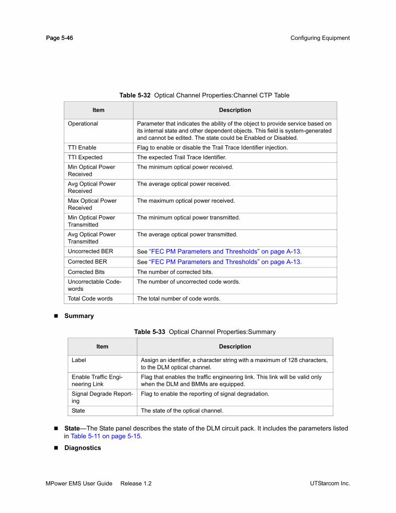
Page 5-46 Configuring EquipmentPage 5-46
Summary
State—The State panel describes the state of the DLM circuit pack. It includes the parameters listed in Table 5-11 on page 5-15.
Diagnostics
Operational Parameter that indicates the ability of the object to provide service based on its internal state and other dependent objects. This field is system-generated and cannot be edited. The state could be Enabled or Disabled.
TTI Enable Flag to enable or disable the Trail Trace Identifier injection.
TTI Expected The expected Trail Trace Identifier.
Min Optical Power Received
The minimum optical power received.
Avg Optical Power Received
The average optical power received.
Max Optical Power Received
The maximum optical power received.
Min Optical Power Transmitted
The minimum optical power transmitted.
Avg Optical Power Transmitted
The average optical power transmitted.
Uncorrected BER See “FEC PM Parameters and Thresholds” on page A-13.
Corrected BER See “FEC PM Parameters and Thresholds” on page A-13.
Corrected Bits The number of corrected bits.
Uncorrectable Code-words
The number of uncorrected code words.
Total Code words The total number of code words.
Table 5-33 Optical Channel Properties:Summary
Item Description
Label Assign an identifier, a character string with a maximum of 128 characters, to the DLM optical channel.
Enable Traffic Engi-neering Link
Flag that enables the traffic engineering link. This link will be valid only when the DLM and BMMs are equipped.
Signal Degrade Report-ing
Flag to enable the reporting of signal degradation.
State The state of the optical channel.
Table 5-32 Optical Channel Properties:Channel CTP Table
Item Description
UTStarcom Inc.MPower EMS User Guide Release 1.2

Page 5-47Equipment and Termination Point Management
Figure 5-20 DLM Optical Channel Properties
PM Configuration
Real Time PM—The Real Time PM tab displays the real time performance statistics for the Optical Channel termination Point. See “Retrieving Real Time PM Data” on page 8-3.
15 Minute History—The 15Min History tab displays the performance statistics for 15 minute inter-vals. See “Retrieving Real Time PM Data” on page 8-3.
Table 5-34 Optical Channel Properties:Diagnostics
Item Description
Trail Trace Identifier (TTI)Insert Flag to enable or disable the TTI injection.
Transmit The TTI string that will be transmitted.
Alarm Reporting Flag that enables the alarm reporting.
Expected The expected TTI.
Receive The received TTI.
PRBS ModeGeneration Flag which enables the generation of PRBS data on the transmit side.
Monitoring Flag which enables the monitoring of bit errors.
Pre-FEC Threshold OrderBER Rate See “FEC PM Parameters and Thresholds” on page A-13.
Table 5-35 Optical Channel Properties:PM Configuration
Item Description
PM Collection Enable Check box that enables PM data to be collected for the Channel termina-tion point.
MPower EMS User Guide Release 1.2UTStarcom Inc.

Page 5-48 Configuring EquipmentPage 5-48
24 Hour History—The 24 Hour History tab displays the performance statistics for 24 Hour intervals. See “Retrieving Real Time PM Data” on page 8-3.
To configure Optical Channel termination point
Step 1 In the Equipment View, right-click the DLM and select Optical Channels. The Optical Channel Properties window is displayed.
Step 2 In the Optical Channel Properties window, enter the parameters required to configure the ter-mination point.
Step 3 To save your changes, click Apply.
Step 4 When you are done, click Close to exit the Optical Channel Properties window.
Configuring TAM Circuit PackPerform the following tasks to configure the TAM circuit pack:
Auto-configure (see “Auto-configuring Circuit Packs” on page 5-22) or pre-configure the circuit pack (see “Pre-configuring Circuit Packs” on page 5-22).
Modify the TAM attributes (see “Modifying TAM Circuit Pack Attributes” on page 5-48). For example, if you pre-configured the TAM circuit pack type, you must configure the TAM circuit type to match the actual type that will be or has been installed.
The MPower GNM supports the configuration of the 1G TAM, 2.5G TAM and 10G TAM. The procedure is the same for both TAM types.
Modifying TAM Circuit Pack AttributesUse TAM Properties to modify the TAM circuit pack attributes. The TAM Properties window includes these panels and attributes:
UTStarcom Inc.MPower EMS User Guide Release 1.2

Page 5-49Equipment and Termination Point Management
Figure 5-21 Configure TAM
Summary—The Summary panel displays a snapshot of information about the equipment. Most parameters are read-only and cannot be edited. The parameters displayed are as listed in the table.
Table 5-36 TAM Properties:Summary
Parameter Description
Label Assign an identifier, a character string with a maximum of 128 characters, to the circuit pack. You can customize the user interface to display the label in the Equipment Tree.
State Displays the current admin state, service state and alarm reporting state of the circuit pack. Refer to the “MPower GNM GUI Conventions” on page 4-12 for the description of the icons used to convey the state information.
The equipment can be in locked, unlocked, or failed state. A state change notifi-cation report is generated whenever an equipment resource is provisioned or pre-provisioned.
Circuit Pack Displays the circuit pack name: TAM.
Installed Equipment The TAM circuit pack type installed in the slot. If the circuit pack is not present in the slot, then the value None is displayed. The following TAM circuit pack types are supported in Release 1.2:
TAM-2-10G—TAM, two 10G ports.
TAM-4-2.5G—TAM, four 2.5G ports.
TAM-4-1G—TAM, four 1G ports.
Provisioned Equipment The configured TAM circuit pack type.
When a circuit pack is pre-configured, the type is set to TAM. You must change the circuit pack type prior to installing or after installing the TAM.
CLEI The Common Language Equipment Identifier of the TAM.
MPower EMS User Guide Release 1.2UTStarcom Inc.

Page 5-50 Configuring EquipmentPage 5-50
Note: The provisioned circuit pack type must match the installed circuit pack type. If not, a circuit pack mismatch alarm is raised. Once the circuit pack type is matched, you cannot change the circuit pack type. To configure a new circuit pack type, you must delete the current cir-cuit pack and then reconfigure the new circuit pack type.
State—The State panel describes the state of the TAM circuit pack. It includes the parameters listed in Table 5-11 on page 5-15.
Version—The Version panel displays the hardware version of the TAM circuit pack. It includes these attributes:
Figure 5-22 TAM Properties: Version
Table 5-37 TAM Properties:Version
Parameter Description
Hardware Version Hardware version of the circuit pack.
Vendor ID The name of the manufacturer (UTStarcom).
Part Number The manufacturer's part number (PN) of the installed equipment. Use this part number to place your order.
Serial Number The manufacturing serial number of the installed equipment.
Manufactured Date The date the circuit pack was manufactured. The manufactured date is dis-played in the form wwyyyy, where:
• ww represents the week
• yyyy represents the year
Firmware Version String value which contains the list of supported firmware versions sepa-rated by commas.
The format is Device Name:(Z1) (Z2); where:
Z1 is the currently installed and running version. Z2 is the version available for install using cold start.
UTStarcom Inc.MPower EMS User Guide Release 1.2

Page 5-51Equipment and Termination Point Management
To invoke TAM Properties window
Step 1 In the Equipment View, right-click the TAM circuit pack and choose Properties. The TAM Prop-erties window is displayed.
Step 2 In the TAM Properties window, enter the required parameters.
Step 3 To save your changes, click Apply.
Step 4 When you are done, click Close to exit the TAM Properties window.
To cold reset a TAM
Note: Cold reset of a TAM circuit pack is allowed only if it is in the ‘Administrative Locked’ or ‘Administrative Maintenance’ state.
Step 1 In the Equipment View, right-click the TAM circuit pack and choose Reset > Cold. A Confirm Message window appears.
Step 2 Click Abandon if you do not want to reset the TAM circuit pack.
Step 3 Click Continue to reset the TAM circuit pack.
Note: Cold reset of a TAM circuit pack affects data traffic.
Configuring TOM Circuit PackPerform the following tasks to configure the TOM circuit pack:
Auto-configure (see “Auto-configuring Circuit Packs” on page 5-22) or pre-configure the circuit pack (see “Pre-configuring Circuit Packs” on page 5-22).
Modify the TOM attributes (see “Modifying TOM Circuit Pack Attributes” on page 5-52). For exam-ple, if you pre-configured the TOM circuit pack, you must configure the TOM circuit pack type to match the actual type that will be or has been installed.
Modify the attributes of the termination points contained within the TOM, including:
Trib Port which represents the physical port on the TOM. It captures the physical characteristics of the client signal. See “Configuring TOM Trib Port Termination Point” on page 5-54 for details on how to configure the Trib PTP.
Client Trib Termination Point which monitors the client signal overhead and is auto-created when the TOM circuit pack is inserted or provisioned. See “Configuring TOM Client Trib Termi-nation Point” on page 5-57 for details on how to configure the Client CTP.
SONET Client Termination Point. See “Configuring SONET Client Termination Point” on page 5-58 for details on how to configure the SONET Client Termination Point.
MPower EMS User Guide Release 1.2UTStarcom Inc.

Page 5-52 Configuring EquipmentPage 5-52
SDH Client Termination Point. See “Configuring SDH Client Termination Point” on page 5-59 for details on how to configure the SDH Client Termination Point.
GbE Client Termination Point. See “Configuring GbE Client Termination Point for 10GBE LAN” on page 5-60 for details on how to configure the GbE Client Termination Point.
The MPower GNM supports the configuration of the 2.5G TOM, 10G TOM and 1G TOM. The following procedure is the same for all TOM types.
Modifying TOM Circuit Pack AttributesUse TOM Properties window to modify the TOM circuit pack attributes. The TOM Properties window includes these panels and attributes:
Figure 5-23 Configure TOM
Summary—The Summary panel displays a snapshot of information about the equipment. Most parameters are read-only and cannot be edited. The parameters displayed are as listed in the table.
Table 5-38 TOM Properties:Summary
Parameter Description
Label Assign an identifier, a character string with a maximum of 128 characters, to the circuit pack. You can customize the user interface to display the label in the Equipment Tree.
State Displays the current admin state, service state and alarm reporting state of the circuit pack. Refer to the “MPower GNM GUI Conventions” on page 4-12 for the description of the icons used to convey the state information.
The equipment can be in locked, unlocked, or maintenance state. A state change notification report is generated whenever an equipment resource is pro-visioned or pre-provisioned.
Circuit Pack Displays the circuit pack name: TOM.
UTStarcom Inc.MPower EMS User Guide Release 1.2

Page 5-53Equipment and Termination Point Management
Note: The provisioned circuit pack type must match the installed circuit pack type. If not, a circuit pack type mismatch alarm is raised. Once the circuit pack is matched, you cannot change the circuit pack type. To configure a new circuit pack type, you must delete the current cir-cuit pack and then reconfigure the new circuit pack type.
State—The State panel describes the state of the TOM circuit pack. It includes the parameters listed in Table 5-11 on page 5-15.
Version—The Version tab displays hardware and software version of the TOM circuit pack. It includes these attributes:
Installed Equipment The TOM circuit pack type installed in the slot. If the circuit pack is not present in the slot, then the value None is displayed. The following TOM circuit pack types are supported in Release 1.2:
TOM-10G-SR1—10G Tributary Optical Module.
TOM-2.5G-SR1—2.5G Tributary Optical Module.
TOM-10G-IR2—10G Tributary Optical Module.
TOM-2.5G-IR1—2.5G Tributary Optical Module.
TOM-1G-LX—1G Tributary Optical Module.
The following TOM circuit pack types, which when inserted into a valid TAM slot, would be auto-provisioned.
TOM-10G-SR2—10G Tributary Optical Module.
TOM-2.5G-IR2—2.5G Tributary Optical Module.
TOM-10G-LR2—10G Tributary Optical Module.
TOM-2.5G-LR2—2.5G Tributary Optical Module.
TOM-1G-SX—1G Tributary Optical Module.
Provisioned Equipment The configured TOM circuit pack type.
When a circuit pack is pre-configured, the type is set to TOM. You must change the circuit pack type prior to installing or after installing the TOM.To support migration to future TOMs, this value is set to TOM. It indicates Generic Tributary Optical Module type.
CLEI The Common Language Equipment Identifier of the TOM.
Table 5-38 TOM Properties:Summary
Parameter Description
MPower EMS User Guide Release 1.2UTStarcom Inc.

Page 5-54 Configuring EquipmentPage 5-54
Figure 5-24 TOM Properties:Version
To invoke TOM Properties window
Step 1 In the Equipment View, right-click the TOM circuit pack and choose Properties. The TOM Prop-erties window is displayed.
Step 2 In the TOM Properties window, enter the required parameters.
Step 3 To save your changes, click Apply.
Step 4 When you are done, click Close to exit the TOM Properties window.
Configuring TOM Trib Port Termination PointThe Trib Port termination point is configured from the Trib Port Properties window.
The Trib Port termination point is auto-created when the TOM circuit pack is created; it is automatically deleted when the TOM is deleted. Use the Trib Port Properties window to configure Trib Port termination point attributes. The Trib Port Properties window includes these panels and attributes:
Table 5-39 TOM Properties:Version
Parameter Description
Hardware Version Hardware version of the circuit pack.
Vendor ID The name of the manufacturer (UTStarcom).
Part Number The manufacturer's part number (PN) of the installed equipment. Use this part number to place your order.
Serial Number The manufacturing serial number of the installed equipment.
Manufactured Date The date the circuit pack was manufactured. The manufactured date is dis-played in the form wwyyyy, where:
• ww represents the week
• yyyy represents the year
UTStarcom Inc.MPower EMS User Guide Release 1.2

Page 5-55Equipment and Termination Point Management
Figure 5-25 TOM Trib Port Properties
Summary
General
Table 5-40 TOM Trib Port Properties:Summary Panel
Item Description
Label Assign an identifier, a character string with a maximum of 128 characters, to the Trib port termination point of the TOM.
State The current operational and service state of the Trib Port termination point. Refer to the “MPower GNM GUI Conventions” on page 4-12 for the description of the icons used to convey the state information.
Table 5-41 TOM Trib Port Properties:General Panel
Item Description
Max Channel Capacity The maximum channel capacity of the signal port of the TOM.
Trib Disable Action Represents the action that will take place when the ter-mination point does not provide service. Valid values can be one of the following:
• Disable laser (LOL)
• Generate AIS-L
• Do nothing
This is set to Disable laser (LOL) for 10G Clear Channel and 10GBE_LAN Provisioned Service Type.
MPower EMS User Guide Release 1.2UTStarcom Inc.

Page 5-56 Configuring EquipmentPage 5-56
State—Use the State panel to view the Trib Port termination point state. For the description of the state attributes, refer to Table 5-11 on page 5-15.
Protection
Real Time—See “Retrieving Real Time PM Data” on page 8-3.
15 Minute History—See “Retrieving PM Data” on page 8-3.
24 Hour History—See “Retrieving PM Data” on page 8-3.
To configure Trib Port termination point
Step 1 In the Equipment View, right-click the TOM and select Trib Port. The Trib Port Properties win-dow is displayed.
Step 2 In the Trib Port Properties window, enter the parameters required to configure the termination point.
Step 3 To save your changes, click Apply.
Step 4 When you are done, click Close to exit the Trib Port Properties window.
Provisioned Service Type The service type supported by the cross-connect.
Valid values can be one of the following:
• OC192/10GbE WAN
• STM64
• 10GBE_LAN
• 10G Clear Channel
Enable PM Collection Flag that enables the collection of performance data.
Table 5-42 TOM Trib Port Properties:Protection
Item Description
Mode The mode of protection (Y cable).
Configured State Indicates the configured state of the Protection Unit.
Direction The direction of the Protection Unit.
Current State Indicates the current state of the Protection Unit.
Table 5-41 TOM Trib Port Properties:General Panel
Item Description
UTStarcom Inc.MPower EMS User Guide Release 1.2

Page 5-57Equipment and Termination Point Management
Configuring TOM Client Trib Termination PointThe TOM Client Trib termination point is auto-created when the TOM is created; it is deleted when the TOM is deleted. Use SONET Client Properties to view and configure Client Trib termination point. The SONET Client Properties window includes these panels and attributes:
Figure 5-26 Configure TOM Client Trib Termination Point
Summary
Diagnostics
Table 5-43 TOM SONET Client Properties:Summary Panel
Item Description
Label Assign an identifier, a character string with a maximum of 128 characters, to the client termination point of the TOM.
Circuit ID A unique identifier provided to identify the circuit.
State The current operational and service state of the Client Trib termination point. Refer to the “MPower GNM GUI Conventions” on page 4-12 for the description of the icons used to convey the state information.
Table 5-44 SONET Client Properties:Diagnostics Panel
Item Description
Configured ServiceType The configured service type.
Loopback Flag to enable the loopback.
Enable PM collection Flag to enable PM collection.
Section Trace(J0)
MPower EMS User Guide Release 1.2UTStarcom Inc.

Page 5-58 Configuring EquipmentPage 5-58
Rx Threshold—See “Configuring Thresholds” on page 8-11.
TxThreshold—See “Configuring Thresholds” on page 8-11.
State—Use the SONET Client Properties State panel to view the Client Trib termination point state. For the description of the state attributes, refer to Table 5-11 on page 5-15.
Real Time PM—The Real Time PM panel displays the real time performance statistics data for the Client Trib termination Point. See “Retrieving Real Time PM Data” on page 8-3.
15 Minute History—The 15Min History tab displays the performance statistics for 15 minute inter-vals. See “Retrieving PM Data” on page 8-3.
24 Hour History—The 24 Hour History tab displays the performance statistics for 24 Hour intervals. See “Retrieving PM Data” on page 8-3.
To configure Client Trib termination point
Step 1 In the Equipment View, right-click the TOM and select Client trib termination point. The SONET Client Properties window is displayed.
Step 2 In the SONET Client Properties window, enter the parameters required to configure the termi-nation point.
Step 3 To save your changes, click Apply.
Step 4 When you are done, click Close to exit the SONET Client Properties window.
Configuring SONET Client Termination PointSee “Modifying TOM Circuit Pack Attributes” on page 5-52 for a description of the attributes.
Receive Received J0 message.
Expected Expected J0 message.
Length The length of J0 byte.
Mismatch Reporting The flag for enabling or disabling the reporting of J0 trace mismatch condition.
Refresh To refresh the PM data displayed.
Table 5-44 SONET Client Properties:Diagnostics Panel
Item Description
UTStarcom Inc.MPower EMS User Guide Release 1.2

Page 5-59Equipment and Termination Point Management
Figure 5-27 SONET Client Properties: TOM
To configure SONET client termination point
Step 1 In the Equipment View, right-click the TOM circuit pack and select Trib Port.... The Trib port Properties window is displayed. From the drop-down menu for Provisioned ServiceType, select OC192/10GbE WAN.
Step 2 To save your changes, click Apply.
Step 3 When you are done, click Close to exit the Trib Port Properties window.
Step 4 In the Equipment View, right-click the TOM circuit pack and select Client trib termination point.... The SONET Client Properties window is displayed.
Step 5 Edit the required parameters. To save your changes, click Apply.
Step 6 When you are done, click Close to exit the SONET Client Properties window.
Configuring SDH Client Termination PointSee “Modifying TOM Circuit Pack Attributes” on page 5-52 for a description of the attributes.
MPower EMS User Guide Release 1.2UTStarcom Inc.

Page 5-60 Configuring EquipmentPage 5-60
Figure 5-28 SDH Client Properties: TOM
To configure SDH client termination point
Step 1 In the Equipment View, right-click the TOM circuit pack and select Trib Port.... The Trib port Properties window is displayed. From the drop-down menu for Provisioned ServiceType, select STM16.
Step 2 To save your changes, click Apply.
Step 3 When you are done, click Close to exit the Trib Port Properties window.
Step 4 In the Equipment View, right-click the TOM circuit pack and select Client trib termination point.... The SDH Client Properties window is displayed.
Step 5 Edit the required parameters. To save your changes, click Apply.
Step 6 When you are done, click Close to exit the SDH Client Properties window.
Configuring GbE Client Termination Point for 10GBE LANSee “Modifying TOM Circuit Pack Attributes” on page 5-52 for a description of the attributes.
UTStarcom Inc.MPower EMS User Guide Release 1.2

Page 5-61Equipment and Termination Point Management
Figure 5-29 GbE Client Properties for 10GBE LAN: TOM
To configure GbE client termination point for 10GbE LAN
Step 1 In the Equipment View, right-click the TOM circuit pack and select Trib Port.... The Trib port Properties window is displayed. From the drop-down menu for Provisioned ServiceType, select 10GBE_LAN.
Step 2 To save your changes, click Apply.
Step 3 When you are done, click Close to exit the Trib Port Properties window.
Step 4 In the Equipment View, right-click the TOM circuit pack and select Client trib termination point.... The GbE Client Properties window is displayed.
Step 5 Edit the required parameters. To save your changes, click Apply.
Step 6 When you are done, click Close to exit the GbE Client Properties window.
Configuring GbE Client Termination Point for 1GBE LANSee “Modifying TOM Circuit Pack Attributes” on page 5-52 for a description of the attributes.
MPower EMS User Guide Release 1.2UTStarcom Inc.

Page 5-62 Configuring EquipmentPage 5-62
Figure 5-30 GbE Client Properties for 1GBE LAN: TOM
To configure GbE client termination point for 1GbE LAN
Step 1 In the Equipment View, right-click the TOM circuit pack and select Trib Port.... The Trib port Properties window is displayed. From the drop-down menu for Provisioned ServiceType, select 1GBE_LAN.
Step 2 To save your changes, click Apply.
Step 3 When you are done, click Close to exit the Trib Port Properties window.
Step 4 In the Equipment View, right-click the TOM circuit pack and select Client trib termination point.... The GbE Client Properties window is displayed.
Step 5 Edit the required parameters. To save your changes, click Apply.
Step 6 When you are done, click Close to exit the GbE Client Properties window.
Configuring Clear Channel Termination PointSee “Modifying TOM Circuit Pack Attributes” on page 5-52 for a description of the attributes.
UTStarcom Inc.MPower EMS User Guide Release 1.2

Page 5-63Equipment and Termination Point Management
Figure 5-31 Clear Channel Properties: TOM
Step 1 In the Equipment View, right-click the TOM circuit pack and select Trib Port.... The Trib port Properties window is displayed. From the drop-down menu for Provisioned ServiceType, select 10G Clear Channel.
Step 2 To save your changes, click Apply.
Step 3 When you are done, click Close to exit the Trib Port Properties window.
Step 4 In the Equipment View, right-click the TOM circuit pack and select Client trib termination point.... The Clear Channel Properties window is displayed.
Step 5 Edit the required parameters. To save your changes, click Apply. If an invalid entry error mes-sage is displayed, the modified fields are retained, so that incorrect entries can be fixed and re-applied.
Step 6 When you are done, click Close to exit the Clear Channel Properties window.
Configuring MCM Circuit PackPerform the following tasks to configure the MCM circuit pack:
Modify the MCM attributes (see “Modifying MCM Circuit Pack Attributes” on page 5-64). For exam-ple, you must configure the MCM circuit type to match the actual type that will be or has been installed.
Note: Pre-configuration need not be done in the case of MCM circuit pack, as it is automatically pre-configured.
MPower EMS User Guide Release 1.2UTStarcom Inc.

Page 5-64 Configuring EquipmentPage 5-64
Modifying MCM Circuit Pack AttributesUse Management Card Properties window to modify the MCM circuit pack attributes. The Management Card Properties window includes these panels and attributes:
Figure 5-32 Configure MCM
Summary - The Summary panel displays a snapshot of the MCM information. The parameters dis-played are as listed in the table.
Table 5-45 MCM Properties:Summary
Parameter Description
Label Assign an identifier, a character string with a maximum of 128 characters, to the circuit pack. You can customize the user interface to display the label in the Equipment Tree.
Circuit Pack Displays the circuit pack name: MCM.
Installed Equipment The MCM circuit pack type installed in the slot. If the circuit pack is not present in the slot, then the value None is displayed.
Provisioned Equipment The configured MCM circuit pack type.
CLEI The Common Language Equipment Identifier of the MCM.
State Displays the current admin state, service state and alarm reporting state of the circuit pack. Refer to the “MPower GNM GUI Conventions” on page 4-12 for the description of the icons used to convey the state information.
The equipment can be in a locked, unlocked, or failed state. A state change noti-fication report is generated whenever an equipment resource is provisioned or pre-provisioned.
UTStarcom Inc.MPower EMS User Guide Release 1.2

Page 5-65Equipment and Termination Point Management
Redundancy—The redundancy panel displays the possible states and the status of the MCM cir-cuit pack.
Note: Only the MCM-B can be in a redundant configuration.
State—The State panel describes the state of the MCM circuit pack. It includes the parameters listed in Table 5-11 on page 5-15.
Figure 5-33 MCM Properties:State
Version—The Version tab displays hardware and software version of the MCM circuit pack. It includes these attributes:
Table 5-46 MCM Properties:Redundancy Panel
Item Description
Redundancy Status Indicates whether the MCM is active or standby.
Table 5-47 MCM Properties:State
Item Description
Admin State See Table 5-11 on page 5-15Service State See Table 5-11 on page 5-15Operational State See Table 5-11 on page 5-15Alarm Reporting See Table 5-11 on page 5-15Alarm Inhibit See Table 5-11 on page 5-15Conditions See Table 5-11 on page 5-15
MPower EMS User Guide Release 1.2UTStarcom Inc.

Page 5-66 Configuring EquipmentPage 5-66
Figure 5-34 MCM Properties:Version
To invoke Management Card Properties window
Step 1 In the Equipment View right-click the MCM circuit pack and choose Properties. The Manage-ment Card Properties window is displayed.
Step 2 In the Management Card Properties window, enter the required parameters.
Step 3 To save your changes, click Apply.
Step 4 When you are done, click Close to exit the Management Card Properties window.
Table 5-48 MCM Properties:Version
Parameter Description
Software Version The software version running on this circuit pack.
Hardware Version Hardware version of the circuit pack.
Manufactured Date The date the circuit pack was manufactured. The manufactured date is dis-played in the form wwyyyy, where:
• ww represents the week
• yyyy represents the year
Serial Number The manufacturing serial number of the installed equipment.
Part Number The manufacturer's part number (PN) of the installed equipment. Use this part number to place your order.
Vendor ID The name of the manufacturer (UTStarcom).
Last Reboot Time Last time the circuit pack was rebooted.
Last Reboot Reason The reason which caused the last circuit pack reboot. Valid values can be one of the following:
Cold—The circuit pack was rebooted due to cold reset.Warm—The circuit pack was rebooted due to warm reset.
None—The circuit pack was not rebooted.
UTStarcom Inc.MPower EMS User Guide Release 1.2

Page 5-67Equipment and Termination Point Management
Configuring OTC Main ChassisThe Optical Transport Chassis (OTC) is present in the Optical Line Amplifier. Every Optical Line Amplifier has one OTC which can be configured by the user. The Equipment View displays the chassis graphically and is identified by the chassis ID. This is the only chassis in the network element. Figure 5-35 displays the different components of the chassis and the color-coding schema.
Figure 5-35 OTC Chassis with pre-provisioned equipment
Every OTC can accommodate:
Up to 2 OMMs in slots 1A and 1B
Up to 2 OAMs in slots 2 and 3
The OTC can be configured from the Chassis Properties window. To configure the chassis, all the chassis’ equipment must be provisioned (either pre-provisioned or auto-provisioned). For details on pre-provisioning, see “To pre-provision circuit packs” on page 5-23.
Figure 5-36 Configure OTC Chassis
The Chassis Properties are grouped as follows:
Provisioned OMM slot
Provisioned and Equipped
Non-Provisioned OWM
OMM
Provisioned and Equipped OAM
MPower EMS User Guide Release 1.2UTStarcom Inc.

Page 5-68 Configuring EquipmentPage 5-68
Summary
State—See “Equipment State Model” on page 5-2.
Version
Temperature—The Temperature panel displays the inlet temperature in degree Centigrade. Click the Refresh button to refresh the inlet temperature.
Table 5-49 Chassis Properties:Summary Panel
Item Description
Label Assign an identifier, a character string with a maximum of 128 char-acters, to the chassis. This name can be changed by the user at any time.
Rack Name Name that is used to group the chassis in the Node View tab of the Quick View Browser.
RU Location in Rack The Rack Unit position of the chassis within the rack.
Inlet Temperature Temperature (in Centigrade) of the circuit pack at the inlet. The temperature is displayed as -1 if the circuit pack does not have a temperature sensor.
CLEI The Common Language Equipment Identifier used during system turn-up. Refer to the UTStarcom TN780 Turn-up and Test Guide for more details.
Serial Number (SN) The serial number of the chassis.
Provisioned SN A user-supplied number provided at system turn-up that specifies the serial number of the chassis inserted. A chassis mismatch alarm is raised if the detected and provisioned serial numbers do not match.
Table 5-50 Chassis Properties:Version
Item Description
Hardware Version Hardware version of the board.
Manufactured Date The date the chassis was manufactured. The date is of the format wwyyyy, where:
• ww is the week
• yyyy is the year of manufacture
Part Number The manufacturer's resource part number (PN) of the installed equipment.
UTStarcom Inc.MPower EMS User Guide Release 1.2

Page 5-69Equipment and Termination Point Management
Figure 5-37 Chassis Properties:Temperature
To configure a OTC chassis
Step 1 In the Equipment View, do one of the following:
Right-click just below the title bar (next to the ACO-OFF/ACO-ON button)
Double-click just below the title bar (next to the ACO-OFF/ACO-ON button)
Figure 5-38 Short Cut Menu for Chassis
Step 2 From the short cut menu, select Properties. The Chassis Properties window is displayed.
Step 3 Enter the required parameters.
Step 4 To save your changes, click Apply.
Step 5 When you are done, click Close to exit the Chassis Properties window.
Configuring OTC Circuit PacksThis section provides procedures to configure the OTC circuit packs. Circuit Packs can be pre-configured or auto-configured. It also provides information on how to access read-only details about an individual circuit pack such as circuit pack identifiers, manufacturing details, currently assigned role and so on.
The OTC provides the following types of circuit packs:
Optical Management Module (OMM)
Optical Amplifier Module (OAM)
The circuit pack is recognized by a standard set of images and colors displayed in the Equipment View. See Figure 5-35 on page 5-67. To ease deployment and meet diverse customer needs, two modes of configuration are supported:
MPower EMS User Guide Release 1.2UTStarcom Inc.

Page 5-70 Configuring EquipmentPage 5-70
Auto-configuration—See “Auto-configuring Circuit Packs” on page 5-22 for more information.
Pre-Configuration—See “Pre-configuring Circuit Packs” on page 5-22 for more information.
OTC circuit packs are configured from the Management Card Properties and OAM Properties windows. The following section describes how to configure the OTC circuit packs.
Configuring OMM Circuit PackPerform the following tasks to configure the OMM circuit pack:
Modify the OMM attributes (see “Modifying OMM Circuit Pack Attributes” on page 5-70). For exam-ple, you must configure the OMM circuit type to match the actual type that will be or has been installed.
Note: Pre-configuration need not be done in the case of OMM circuit pack, as it is automatically pre-configured.
Modifying OMM Circuit Pack AttributesUse Management Card Properties window to modify the OMM circuit pack attributes. The Management Card Properties window includes these panels and attributes:
UTStarcom Inc.MPower EMS User Guide Release 1.2

Page 5-71Equipment and Termination Point Management
Figure 5-39 Configure OMM
Summary - The Summary panel displays a snapshot of the OMM information. The parameters dis-played are as listed in Table 5-51.
Table 5-51 OMM Properties:Summary
Parameter Description
Label Assign an identifier, a character string with a maximum of 128 characters, to the circuit pack. You can customize the user interface to display the label in the Equipment Tree.
Circuit Pack Displays the circuit pack name: OMM A or OMM B.
Installed Equipment The OMM circuit pack type installed in the slot. If the circuit pack is not present in the slot, then the value None is displayed.
Provisioned Equipment The configured OMM circuit pack type.
CLEI The Common Language Equipment Identifier of the OMM.
State Displays the current admin state, service state and alarm reporting state of the circuit pack. Refer to the “MPower GNM GUI Conventions” on page 4-12 for the description of the icons used to convey the state information.
The equipment can be in locked, unlocked, or shutdown state. A state change notification report is generated whenever an equipment resource is provisioned or pre-provisioned.
MPower EMS User Guide Release 1.2UTStarcom Inc.

Page 5-72 Configuring EquipmentPage 5-72
Redundancy—The redundancy panel displays the status of the OMM circuit pack.
State—The State panel describes the state of the OMM circuit pack. It includes the parameters listed in Table 5-11 on page 5-15.
Figure 5-40 OMM Properties:State
Version—The Version panel displays hardware and software version of the OMM circuit pack. It includes these attributes:
Table 5-52 OMM Properties:Redundancy Panel
Item Description
Redundancy Status Indicates whether the OMM is active or standby.
Table 5-53 OMM Properties:State
Item Description
Admin State See Table 5-11 on page 5-15Service State See Table 5-11 on page 5-15Operational State See Table 5-11 on page 5-15Alarm Reporting See Table 5-11 on page 5-15Alarm Inhibit See Table 5-11 on page 5-15Conditions See Table 5-11 on page 5-15
UTStarcom Inc.MPower EMS User Guide Release 1.2

Page 5-73Equipment and Termination Point Management
Figure 5-41 OMM Properties:Version
To invoke Management Card Properties window
Step 1 In the Equipment View right-click the OMM circuit pack and choose Properties. The Manage-ment Card Properties window is displayed.
Step 2 In the Management Card Properties window, enter the required parameters.
Step 3 To save your changes, click Apply.
Step 4 When you are done, click Close to exit the Management Card Properties window.
Table 5-54 OMM Properties:Version
Parameter Description
Software Version The software version running on this circuit pack.
Hardware Version Hardware version of the circuit pack.
Manufactured Date The date the circuit pack was manufactured. The manufactured date is dis-played in the form wwyyyy, where:
• ww represents the week
• yyyy represents the year
Serial Number The manufacturing serial number of the installed equipment.
Part Number The manufacturer's part number (PN) of the installed equipment. Use this part number to place your order.
Vendor ID The name of the manufacturer (UTStarcom).
Last Reboot Time Last time the circuit pack was rebooted.
Last Reboot Reason The reason which caused the last circuit pack reboot. Valid values can be one of the following:
Cold—The circuit pack was rebooted due to cold reset.Warm—The circuit pack was rebooted due to warm reset.
None—The circuit pack was not rebooted.
MPower EMS User Guide Release 1.2UTStarcom Inc.

Page 5-74 Configuring EquipmentPage 5-74
Configuring OAM Circuit PackPerform the following tasks to configure the OAM circuit pack:
Auto-configure (see “Auto-configuring Circuit Packs” on page 5-22) or pre-configure the circuit pack (see “Pre-configuring Circuit Packs” on page 5-22).
Modify the OAM attributes (see “Modifying OAM Circuit Pack Attributes” on page 5-74). For exam-ple, if you pre-configured the OAM circuit pack, you must configure the OAM circuit pack type to match the actual type that will be or has been installed.
Modify the attributes of the termination points contained within the OAM, including:
Span termination point which represents the Optical Transport Section (OTS) and C-Band termi-nation. See “Configuring OAM Span Termination Point” on page 5-79.
OSC (Optical Supervisory Channel) termination point which represents the OSC channel termi-nation. See “Configuring OAM OSC Termination Point” on page 5-78.
GMPLS (Generalized Multi-Protocol Label Switching) Link termination point which represents the OSPF and GMPLS control protocol termination on this span. See “Configuring OAM GMPLS Links” on page 5-82.
Modifying OAM Circuit Pack AttributesUse OAM Properties to modify the OAM circuit pack attributes. The OAM Properties window includes these panels and attributes:
UTStarcom Inc.MPower EMS User Guide Release 1.2

Page 5-75Equipment and Termination Point Management
Figure 5-42 Configure OAM
Summary—The Summary panel displays a snapshot of information about the equipment. Most parameters are read-only and cannot be edited. The parameters displayed are as listed in the table.
Table 5-55 OAM Properties:Summary
Parameter Description
Label Assign an identifier, a character string with a maximum of 128 characters, to the circuit pack. You can customize the user interface to display the label in the Equipment Tree.
Circuit Pack Displays the circuit pack name: OAM.
Installed Equipment The OAM circuit pack type installed in the slot. If the circuit pack is not present in the slot, then the value None is displayed. The following OAM circuit pack types are supported in Release 1.2:
OAM-C1—OAM, C band, 20 dB fixed gain, with VOA, without mid-stage access.
OAM-C2-MS—OAM, C band, variable gain from 18 dB to 26 dB, with mid-stage access.
OAM-C3-MS—OAM, C band, variable gain from 25 dB to 33 dB, with mid-stage access.
Provisioned Equipment The configured OAM circuit pack type.
CLEI The Common Language Equipment Identifier of the OAM.
MPower EMS User Guide Release 1.2UTStarcom Inc.

Page 5-76 Configuring EquipmentPage 5-76
Note: The provisioned circuit pack type must match the installed circuit pack type. If not, a circuit pack mismatch alarm is raised. Once the circuit pack type is matched, you cannot change the circuit pack type. To configure a new circuit pack type, you must delete the current cir-cuit pack and then reconfigure the new circuit pack type.
OAM State—The OAM State panel describes the state of the OAM circuit pack. It includes the parameters listed in Table 5-11 on page 5-15.
OAM Version—The OAM Version tab displays hardware and software version of the OAM circuit pack. It includes these attributes:
Figure 5-43 OAM Properties:Version
DCM Port State Displays the current service state and alarm reporting state of the DCM port. Refer to the “MPower GNM GUI Conventions” on page 4-12 for the description of the icons used to convey the state information.
OAM State Displays the current admin state, service state and alarm reporting state of the circuit pack. Refer to the “MPower GNM GUI Conventions” on page 4-12 for the description of the icons used to convey the state information.
The equipment can be in a locked, unlocked, or shutdown state. A state change notification report is generated whenever an equipment resource is provisioned or pre-provisioned.
Table 5-56 OAM Properties:Version
Parameter Description
Software Version The software version running on this circuit pack.
Serial Number The manufacturing serial number of the installed equipment.
Manufactured Date The date the circuit pack was manufactured. The manufactured date is dis-played in the form wwyyyy, where:
• ww represents the week
• yyyy represents the year
Table 5-55 OAM Properties:Summary
Parameter Description
UTStarcom Inc.MPower EMS User Guide Release 1.2

Page 5-77Equipment and Termination Point Management
DCM Port—Use the DCM Port panel to view and configure the DCM (Dispersion Compensation Module) connected to the DCM port on the OAM circuit pack.
DCM Port State—Use the DCM Port State panel to view the DCM port state. For a description of the state attributes, refer to Table 5-11 on page 5-15.
To invoke OAM Properties window
Step 1 In the Equipment View right-click the OAM circuit pack and choose Properties. The OAM Prop-erties window is displayed.
Step 2 In the OAM Properties window, enter the required parameters.
Step 3 To save your changes, click Apply.
Step 4 When you are done, click Close to exit the OAM Properties window.
Last Reboot Time Last time the circuit pack was rebooted.
Hardware Version Hardware version of the circuit pack.
Vendor ID The name of the manufacturer (UTStarcom).
Part Number The manufacturer's part number (PN) of the installed equipment. Use this part number to place your order.
Last Reboot Reason The reason which caused the last circuit pack reboot. Valid values can be one of the following:
Cold—The circuit pack was rebooted due to cold reset.Warm—The circuit pack was rebooted due to warm reset.
None—The circuit pack was not rebooted. Firmware Version String value which contains the list of supported firmware versions sepa-
rated by commas.
The format is Device Name:(Z1) (Z2); where:
Z1 is the currently installed and running version. Z2 is the version available for install using cold start.
Table 5-57 OAM Properties:DCM Panel
Item Description
Dispersion CompensationDCM Type Select the DCM type from a drop-down menu. The DCM types are listed
in Table 5-16 on page 5-27.
Expected Dcf Loss The expected DCF loss in dB.
Expected Dispersion The expected dispersion in ps/nm.
Table 5-56 OAM Properties:Version
Parameter Description
MPower EMS User Guide Release 1.2UTStarcom Inc.

Page 5-78 Configuring EquipmentPage 5-78
Configuring OAM OSC Termination PointThe OSC termination point is auto-created when the OAM circuit pack is created; it is automatically deleted when the OAM is deleted. Use the OSC Properties window shown in Figure 5-45 on page 5-80 to configure OSC termination point attributes.
Figure 5-44 OAM OSC Properties
The OSC Properties window includes these panels and attributes:
Summary—See Table 5-17 on page 5-29 for a description of the attributes.
OSC IP Address—The OSC IP Address panel displays information about the OSC connection. See Table 5-18 on page 5-30 for a description of the attributes.
General—See Table 5-19 on page 5-30 for a description of the attributes.
State—Use the State panel to view the OSC termination point state. For a description of the state attributes, refer to Table 5-11 on page 5-15.
RealTime PM—Displays the OSC real-time PM data.
15Min History—Displays the OSC 15-min historical PM data. See “Retrieving PM Data” on page 8-3.
24Hour History—Displays the OSC 24-hr historical PM data. See “Retrieving PM Data” on page 8-3.
UTStarcom Inc.MPower EMS User Guide Release 1.2

Page 5-79Equipment and Termination Point Management
To configure OAM OSC IP address
Step 1 Do one of the following:
In the Equipment View, right-click the OAM and choose OSC... The OSC Properties window is displayed. In the OSC IP Address panel, click Edit.... The GMPLS Link Properties win-dow is displayed.
In the Equipment View, right-click the OAM and choose GMPLS Link.... The GMPLS Link Properties window is displayed
Step 2 In the OSC IP Address panel, check Enable.
Step 3 Enter the desired IP address and subnet mask.
Step 4 To save your changes, click Apply.
Step 5 When you are done, click Close to exit the GMPLS Properties window.
Step 6 Click Close to exit the OSC Properties window.
To configure OAM OSC termination point
Step 1 In the Equipment View, right-click the OAM and choose OSC. The OSC Properties window is displayed.
Step 2 In the OSC Properties window, enter the desired parameters.
Step 3 To save your changes, click Apply.
Step 4 When you are done, click Close to exit the OSC Properties window.
Configuring OAM Span Termination PointThe Span termination point is auto-created when the OAM is created; it is deleted when the OAM is deleted. Use Span Properties window shown in Figure 5-45 on page 5-80 to view and configure Span termination points.
MPower EMS User Guide Release 1.2UTStarcom Inc.

Page 5-80 Configuring EquipmentPage 5-80
Figure 5-45 OAM Span Properties
The Span Properties window includes these panels and attributes:
Summary
Table 5-58 OAM Span Properties:Summary
Item Description
OTS AID Displays the OTS termination point ID in the <Chassis>-<Service-Shelf>-<OAMSlot>-<LinePort> format where:
Chassis = 1 in Release 1.2.
Service-Shelf = A
OAMSlot = 1 or 2
LinePort = L1
Band AID Displays the Band termination point ID in the <Chassis>-<Service-Shelf>-<OAMSlot>-<Band> format where:
Chassis = 1 in Release 1.2
Service-Shelf = A
OAMSlot = 1 or 2
Band = C for C-Band in Release 1.2
Label Assign a label, a character string with a maximum of 128 characters, to this span.
UTStarcom Inc.MPower EMS User Guide Release 1.2

Page 5-81Equipment and Termination Point Management
Span/C-Band—See Table 5-21 on page 5-33 for a description of the attributes.
OTS State—Use the OTS State panel to view the OTS termination point state. For a description of the state attributes, refer to Table 5-11 on page 5-15.
Band State—Use the Band State panel to view the Band termination point state. For a description of the state attributes, refer to Table 5-11 on page 5-15.
Span/C-Band Real Time PM—Displays the real-time PM data for the Span and Band termination points. See “Retrieving Real Time PM Data” on page 8-3. For a description of these parameters, see “Optical PM Parameters and Thresholds” on page A-2. For a description of the PM data collection procedures, see “Retrieving PM Data” on page 8-3.
C-Band 15Min History—Displays the C-Band 15-min historical PM data. For a description of these parameters, see “Optical PM Parameters and Thresholds” on page A-2. For a description of the PM data collection procedures, see “Retrieving PM Data” on page 8-3.
OTS State The current operational and service state of the OTS termination point. Refer to the “MPower GNM GUI Conventions” on page 4-12 for the description of the icons used to convey the state information.
Band State The current operational and service state of the Band termination point. Refer to the “MPower GNM GUI Conventions” on page 4-12 for a description of the icons used to convey the state information.
Table 5-59 OAM Span Properties:Optical Span
Item Description
FiberRx Fiber Type The type of Rx fiber used for physical connectivity.
Tx Fiber Type The type of Tx fiber used for physical connectivity.
Span Loss ThresholdHigh The highest value to which the power can rise before an alarm is raised.
This data must be supplied for both the receiving end and the transmitting ends.
Low The lowest value to which the power can drop before an alarm is raised. This data must be supplied for both the receiving end and the transmitting ends.
High/Low Reporting Flag that enables the reporting of alarms when threshold limits are crossed. By default, alarm reporting is disabled.
Expected Span Loss (ESL)
Expected power on this fiber. This value varies based on span length, con-nectors and so on. This attribute is configured by the user.
Detected Rx Power The detected Rx power (in dB).
Detected Span Loss The detected span loss (in dB).
Table 5-58 OAM Span Properties:Summary
Item Description
MPower EMS User Guide Release 1.2UTStarcom Inc.

Page 5-82 Configuring EquipmentPage 5-82
C-Band 24Hour History—Displays the C-Band 24-hr historical PM data. For a description of these parameters, see “Optical PM Parameters and Thresholds” on page A-2. For a description of the PM data collection procedures, see “Retrieving PM Data” on page 8-3.
L-Band Real Time PM—Displays the L-Band 15-min historical PM data. See “Retrieving Real Time PM Data” on page 8-3. The L-Band PM data is supported for testing purposes only.
Configuring OAM GMPLS LinksUse GMPLS Link Properties window to view and configure GMPLS links.
The GMPLS link will function only when the circuit pack is equipped. However, the GMPLS link can be configured beforehand. When the circuit pack is inserted, all GMPLS links associated with the circuit pack are automatically activated.
The GMPLS Link Properties window includes these panels and attributes:
Node—Indicates the selected network element.
OSC IP Address
General
Routing Info
Table 5-60 OAM GMPLS Link Properties: OSC IP Address
Item Description
Enable To enable the OSC IP address.
IP Address The IP address.
Subnet Mask The IP subnet mask.
Table 5-61 OAM GMPLS Link Properties:Summary
Item Description
Link Name The name of the link.
Admin Cost The cost associated with this link.
GMPLS NodeID The GMPLS Node ID.
Table 5-62 OAM GMPLS Link Properties:Routing Info
Item Description
Enable/Disable GMPLS To enable/disable GMPLS.
UTStarcom Inc.MPower EMS User Guide Release 1.2

Page 5-83Equipment and Termination Point Management
Note: For proper adjacency to be formed and maintained along a link, the nodes on the two ends should have the GMPLS Hello Interval and GMPLS Dead Interval parameters matching along that link.
Figure 5-46 OAM GMPLS Link Properties
To configure a GMPLS link
Step 1 In the Equipment View, right-click the OAM circuit pack and select GMPLS Link.... The GMPLS Properties window is displayed.
Step 2 Select or edit the required attributes.
Step 3 To save your changes, click Apply.
Step 4 When you are done, click Close to exit the GMPLS Properties window.
Configuring DTC and OTC PEMThe PEM is configured from the Power Entry Modules Properties window.
GMPLS Hello Interval The periodicity at which Hello messages are sent on a link that has GMPLS routing enabled on it.
GMPLS Dead Interval The time interval after which the routing adjacency along a link will be brought down if no routing protocol activity is seen on it.
Table 5-62 OAM GMPLS Link Properties:Routing Info
Item Description
MPower EMS User Guide Release 1.2UTStarcom Inc.

Page 5-84 Configuring EquipmentPage 5-84
To configure PEM
Step 1 In the Equipment View, right-click the PEM and select Properties or
In the Equipment Tree, right-click PEM and select Properties.
The Power Entry Modules Properties window is displayed.
Step 2 In the Power Entry Modules Properties window, enter the parameters.
Step 3 To save your changes, click Apply.
Step 4 When you are done, click Close to exit the Power Entry Modules Properties window.
Figure 5-47 PEM and FAN display
Figure 5-48 PEM Properties
The PEM Properties are grouped as follows:
Summary—The Summary panel provides a snapshot of the PEM information. See Table 5-10 on page 5-14.
State—See “Equipment State Model” on page 5-2.
PEM Power CordFAN
UTStarcom Inc.MPower EMS User Guide Release 1.2

Page 5-85Equipment and Termination Point Management
Version
Configuring DTC and OTC FANThe FAN is configured from the FAN Module Properties window.
To configure FAN
Step 1 In the Equipment View, right-click the FAN and select Properties or
In the Equipment Tree, right-click FAN and select Properties.
The FAN Module Properties window is displayed.
Step 2 In the FAN Module Properties window, enter the parameters.
Step 3 To save your changes, click Apply.
Step 4 When you are done, click Close to exit the FAN Module Properties window.
Table 5-63 PEM Properties:Version
Item Description
Hardware Version Version of the board.
Manufactured Date The date the circuit pack was manufactured. The date is of the for-mat wwyyyy, where:
• ww is the week
• yyyy is the year of manufacture
Serial Number Defines the manufacturing serial number of the installed equipment and does not change during the lifetime of the FRU.
Part Number The manufacturer's resource part number (PN) of the installed equipment.
Vendor ID The name of the manufacturer.
MPower EMS User Guide Release 1.2UTStarcom Inc.

Page 5-86 Configuring EquipmentPage 5-86
Figure 5-49 FAN Properties
The FAN Properties are grouped as follows:
Summary—The Summary panel provides a snapshot of the FAN information. See Table 5-49 on page 5-68.
State—See “Equipment State Model” on page 5-2.
Version
Resetting DTC and OTC Circuit PacksThe BMM, DLM, MCM, OMM and OAM cards can be reset. The Digital Optical Network supports the following types of resets:
Table 5-64 FAN Properties:Version
Item Description
Hardware Version Version of the board.
Manufactured Date The date the circuit pack was manufactured. The date is of the for-mat wwyyyy, where:
• ww is the week
• yyyy is the year of manufacture
Serial Number Defines the manufacturing serial number of the installed equipment and does not change during the lifetime of the FRU.
Part Number The manufacturer's resource part number (PN) of the installed equipment.
Vendor ID The name of the manufacturer.
UTStarcom Inc.MPower EMS User Guide Release 1.2

Page 5-87Equipment and Termination Point Management
Warm
Cold
The TAM card can be cold-reset.
Note: Resetting circuit packs is potentially service affecting. Performing a cold reboot of the OAM, BMM and DLM circuit packs is disruptive to service. These resets are not dataplane affect-ing.
To reset a circuit pack
Step 1 In the Equipment View, right-click the circuit pack you would like to reset.
Step 2 Select Reset > Warm (or Cold).
When the MCM card is reset, the connection to the MPower GNM is lost and a warning message is displayed indicating the same.
Note: MCM cold reset performs the additional BPOST test. MCM warm reset is sufficient unless MCM hardware issues are suspected.
Deleting DTC and OTC Circuit PacksA circuit pack can be deleted if it is not in use.
Ensure the following before a circuit pack is deleted:
The circuit pack is in Lock state. This prevents any new provisioning operations to be executed.
Delete all cross-connects that use the circuit pack. To view the cross-connects use the Cross-Con-nect Manager. See “Manual Cross-Connect Provisioning” on page 7-7 for details on how to use the Cross-Connect Manager.
Delete all sub-network connections and end-to-end circuits. See “Manual Cross-Connect Provision-ing” on page 7-7 for details on how to use the Cross-Connect Manager. If these connections have not been deleted, an error message is displayed prompting the connections to be deleted.
Note: Deleting a circuit pack may result in the loss of provisioning and configuration information related to the card.
To delete a circuit pack or any of it’s components, the component must first be locked. Locking of a circuit pack ensures that no further action can be performed on the component.
MPower EMS User Guide Release 1.2UTStarcom Inc.

Page 5-88 Configuring EquipmentPage 5-88
To delete a circuit pack
Step 1 Right-click the circuit pack icon and do one of the following:
Select Admin State > Locked.
Select Properties. In the State panel, select Locked from the Admin State list. Click OK to save the changes.
Step 2 Right-click the circuit pack and select Delete. A Warning Message is displayed.
Confirm the deletion of the circuit pack. This process may take some time. A Success Message is displayed when the procedure is complete.
Configuring LinksThe GMPLS Link represents OCG links between network elements. It is the data plane connectivity of the Digital Optical Network. GMPLS links do not carry any control traffic and hence neighbor discovery must to be done out-of-band. Refer “Configuring BMM GMPLS Links” on page 5-37 for a procedure to configure the BMM GMPLS links.
Control links represent the fiber between the network elements. Control links are auto-created by the network element when OSC connectivity is established. Control links are discovered using the OSPF Hello Protocol. The OSC on the physical fiber carries the control traffic destined to network elements within the Digital Optical Network. Neighbor discovery for these links is done in-band.
IO ShelfThe IO shelf contains the ACO indicator, the FANs, PEMs and the NCT.
To invoke the IOShelf Properties window
Do one of the following:
In the Equipment Tree, right-click IOSHELF and select Properties. The IOShelf Properties window is displayed.
In the Equipment View, right-click the space between the PEM and the FAN and select Properties. The IOShelf Properties window is displayed.
UTStarcom Inc.MPower EMS User Guide Release 1.2

Page 5-89Equipment and Termination Point Management
Figure 5-50 IO Shelf Properties
The parameters displayed are as listed in Table 5-65.
Table 5-65 IOShelf Properties
Item Description
CLEI The Common Language Equipment Identifier of the IO Shelf.
Serial Number Defines the manufacturing serial number of the IO Shelf and does not change during the lifetime of the FRU.
Hardware Version Hardware Version of the IO Shelf.
Part Number The manufacturer's resource part number (PN) of the IO Shelf.
Manufactured Date The date of manufacture.
MPower EMS User Guide Release 1.2UTStarcom Inc.

Page 5-90 Viewing Equipment and Termination Point InventoryPage 5-90
Viewing Equipment and Termination Point InventoryThe MPower GNM provides inventory tools to view configured equipment and termination points on the target network element. The inventory tools provided are:
“Equipment Manager” on page 5-90
“Facility Manager” on page 5-93
“Link Manager” on page 5-95
Equipment ManagerThe Equipment Manager displays an equipment inventory for the target network element in a tabular format. Filter operations allow users to customize how the information is displayed. The Equipment Manager allows you to launch context-sensitive applications that perform fault management, configuration and provisioning operations using short-cut menu options. These options are available when you right-click a row in the Equipment Table.
Figure 5-51 Equipment Manager
The Equipment Manager is divided into the panels as described below.
Filter Panel
The Filter panel allows you to filter data based on equipment type like chassis, circuit pack type, fan or PEM, NCT/GbE, IOSHELF. If no filter criteria is selected, the Filter list displays None. The filter option is disabled until all the data is retrieved. To filter equipment:
Search PanelFilter Panel
Equipment Table
Equipment Count
UTStarcom Inc.MPower EMS User Guide Release 1.2

Page 5-91Equipment and Termination Point Management
Select the equipment type from the Filter drop-down menu. The list of equipment matching this filter criteria is displayed in the Equipment Table.
Search Panel
The Search panel allows you to search for equipment based on any of the parameters required to configure the equipment. To search for an equipment:
Enter the search string in the Search panel. The list of equipment matching this search criteria is displayed in the Equipment Table.
Equipment Table
The Equipment Table displays the configured equipment on the target network element. The param-eters displayed are as listed in Table 5-66.
Table 5-66 Equipment Manager:Equipment Table
Item Description
Service State See “Equipment State Model” on page 5-2.
AID An access identifier used to uniquely identify the equipment.Prov Equipment The circuit pack being provisioned. Every circuit pack has different type
of equipment displayed.
Install Equipment The physical equipment type. This is provided at the time of network element turn-up. Refer to the UTStarcom TN780 Turn-up and Test Guide for more details.
Label A name given to the equipment to identify it. This name is entered at the time of configuration and can be a maximum of 128 characters long.
CLEI The Common Language Equipment Identifier used during network ele-ment turn-up. See UTStarcom TN780 Turn-up and Test Guide for more details.
Admin State See “Equipment State Model” on page 5-2.
Operational State See “Equipment State Model” on page 5-2.
Alarm Reporting Flag that enables alarm reporting.
Alarm Inhibit Flag that indicates if alarms are allowed or inhibited.
Part # The manufacturer's resource part number (PN) of the installed equip-ment.
Serial # The manufacturing serial number of the installed equipment and does not change during the lifetime of the FRU.
Hardware Version Version of the board.
Mfg. Date The date the circuit pack was manufactured. The date is of the format wwyyyy, where:
• ww is the week
• yyyy is the year of manufacture
Vendor ID The name of the manufacturer (UTStarcom).
MPower EMS User Guide Release 1.2UTStarcom Inc.

Page 5-92 Viewing Equipment and Termination Point InventoryPage 5-92
Equipment Count
The Equipment Count panel displays the configured components number as against the total num-ber of components configured for the target network element. The count of configured equipment displayed is context sensitive and displays a count of the selected equipment in filter panel.
To invoke the Equipment Manager
Step 1 Select Configuration > Equipment Manager.
The Equipment Manager is displayed in the Workspace Area.
To view equipment inventory
The configured equipment for a network element can be viewed from the Equipment Manager.
Step 1 From the MPower GNM Main Menu, select Configuration > Equipment Manager. The Equip-ment Manager is displayed in the Workspace Area.
Step 2 To view the properties of equipment, right-click a row and select Properties. The Equipment Properties window is displayed.
To export equipment inventory
Equipment information can be stored in a file by exporting the equipment configuration data. All the information is stored in the TSV file format.
Step 1 In the Equipment Manager, click Export to save the equipment information to a file. The Save dialog box is displayed.
Step 2 Navigate to the directory location where you would like to save this file. Enter the name of the file and click Save.
The equipment configuration data is now saved to a file.
Firmware SA Upgrade Indicates if there are pending upgrades. Valid values can be one of the following:
• Pending
• NONE (indicated by a blank space)
Firmware Version String value which contains the list of supported firmware versions sep-arated by commas.
The format is Device Name:(Z1) (Z2); where:
Z1 is the currently installed and running version. Z2 is the version avail-able for install using cold start.
Table 5-66 Equipment Manager:Equipment Table
Item Description
UTStarcom Inc.MPower EMS User Guide Release 1.2

Page 5-93Equipment and Termination Point Management
Facility ManagerThe Facility Manager displays an inventory of the termination points on the target network element in a tabular format. Filter operations allow users to customize how the information is displayed. The Facility Manager allows you to launch context-sensitive applications to perform fault management, configuration operations. These options are available when you right-click any termination point in the Facility Table.
Figure 5-52 Facility Manager
The Facility Manager is divided into the panels as described below.
Filter Panel
The Filter panel allows you to filter data based on the termination point type. If no filter criteria is selected, the Filter displays None. To filter termination points:
Select the termination point type from the Filter drop-down menu. The list of termination points matching this filter criteria is displayed in the Termination Point Table.
Search Panel
The Search panel allows you to search for a termination point based on any of the parameters required to configure the termination point. To search for a termination point:
Enter the search string in the Search panel. The list of termination points matching this search criteria is displayed in the Termination Point Table.
Termination Point Table
Search panelFilter panel
Termination Point
Termination Point
Table
Count
MPower EMS User Guide Release 1.2UTStarcom Inc.

Page 5-94 Viewing Equipment and Termination Point InventoryPage 5-94
The Termination Point Table displays the termination points on the target network element. The parameters displayed are as listed in Table 5-67.
Termination Point Count
The Termination Point Count panel displays the number of termination points displayed as against the total number of termination points on the target network element. The count of termination points displayed depends on the termination point selected in the Filter Panel against the total number of termination points configured on the network element.
To invoke the Facility Manager
Select Configuration > Facility Manager.
The Facility Manager is displayed in the Workspace Area.
To view Facility inventory on the network element
The termination points for a network element can be viewed from the Facility Manager.
Step 1 Select Configuration > Facility Manager. The Facility Manager is displayed in the Workspace Area.
Step 2 To view the properties of a termination point, right-click and select Properties. The Termination Point Properties window is displayed.
Table 5-67 Facility Manager:Termination Point Table
Item Description
Alarm State See “Equipment State Model” on page 5-2.
Service State See “Equipment State Model” on page 5-2.
Facility The termination point type.
AID An access identifier used to uniquely identify the equipment.Label Assign an identifier, a character string with a maximum of 128 charac-
ters, assigned to the termination point.
Admin State See “Equipment State Model” on page 5-2.
Operational State See “Equipment State Model” on page 5-2.
Alarm Report State Parameter that allows the ability to suppress all alarm reporting. The values allowed are Allowed and Inhibited.
Alarm Inhibit State Flag that indicates if the alarms are allowed or inhibited.
Actual/Detected Pay-load
Payload detected at this termination point.
Config/Expected Pay-load
Payload expected at this termination point.
UTStarcom Inc.MPower EMS User Guide Release 1.2

Page 5-95Equipment and Termination Point Management
To export Facility inventory
Termination point information can be stored in a file by exporting the termination point configuration data. All the information is stored in TSV file format.
Step 1 In the Facility Manager, click Export to save the equipment information to a file. The Save dialog box is displayed.
Step 2 Navigate to the directory location where you would like to save this file. Enter the name of the file and click Save.
The termination point configuration data is now saved to a file.
Link ManagerThe Link Manager displays an inventory of the links with the source node and destination node in a tabular format. Filter operations allow users to customize how the information is displayed. The Link Manager allows you to search and export these details.
Figure 5-53 Link Manager
The Link Manager is divided into the panels as described below.
Filter Panel
The Filter panel allows you to filter data based on the node. If no filter criteria is selected, the Filter displays None. To filter nodes, select the link type from the Filter drop-down menu. The list of links matching this filter criteria is displayed in the Link Table.
Search Panel
The Search panel allows you to search for a link based on any of the parameters required to config-ure the link. To search for a link, enter the search string in the Search panel. The list of links match-ing this search criteria is displayed in the Link Table.
Link Table
MPower EMS User Guide Release 1.2UTStarcom Inc.

Page 5-96 Viewing Equipment and Termination Point InventoryPage 5-96
The Link Table displays the links along with the source node and destination node. The parameters displayed are as listed in Table 5-67.
Link Count
The Link Count panel displays the number of links displayed as against the total number of links on the target network element. The count of links displayed depends on the link selected in the Filter Panel against the total number of links configured on the network element.
To invoke the Link Manager
Step 1 Select Configuration > Link Manager.The Link Manager is displayed in the Workspace Area.
To export Link inventory
Link information can be stored in a file by exporting the link data. All the information is stored in the TSV file format.
Step 1 In the Link Manager, click Export to save the equipment information to a file. The Save dialog box is displayed.
Step 2 Navigate to the directory location where you would like to save this file. Enter the name of the file and click Save.
The link data is now saved to a file.
Table 5-68 Link Manager:Link Table
Item Description
Label A unique identifier, a character string with a maximum of 128 charac-ters, assigned to the link.
Origin Node The source node of the link.
Origin Fiber The type of fiber used for physical connectivity.
Origin OCG The originating OCG termination point.
Destination Node The destination node of the link.
Destination OCG The destination OCG termination point.
Scope The scope of the link.
Cost The cost associated with using the link.
TE Enabled Flag that indicates whether the TE link participates in routing and sig-naling.
UTStarcom Inc.MPower EMS User Guide Release 1.2

Page 5-97Equipment and Termination Point Management
Configuring TemplatesPre-packaged default templates are provided to ease pre-provisioning of chassis and circuit packs. The default templates consist of default values for the most commonly configured attributes.
Default templates have the following sets of default values:
Factory Default—These are default values provided by UTStarcom and cannot be edited.
Custom Default—These are default values provided by the user while creating templates. Every chassis or circuit pack has different attributes that can be set. All values edited are indicated by a yellow background. At any time the values set can be discarded and values be restored to factory- provided values.
Modifying the Default DTC Chassis TemplateThe chassis’ attributes for which default values can be set are:
Label
Admin State
Alarm Reporting
See “Configuring DTC Main Chassis” on page 5-13 for a description of the attributes.
To modify the chassis template
Step 1 From the MPower GNM Main Menu, select Configuration > Default Templates.
Step 2 Select Chassis. The Template Properties window is displayed.
MPower EMS User Guide Release 1.2UTStarcom Inc.

Page 5-98 Configuring TemplatesPage 5-98
Figure 5-54 Template Properties for Chassis
Step 3 Enter the values that you would like to set as default. See “Configuring DTC Main Chassis” on page 5-13 for a description of attributes.
Step 4 To save your changes, click Apply.
Step 5 When you are done, click Close to exit the Template Properties window.
Modifying the Default BMM TemplateThe BMM Template Properties window displays the BMM and its termination points’ attributes. These values are grouped by termination points and divided into panels. BMM attributes for which default values can be set are grouped under the following panels:
BMM
OSC
C-Band
Optical Carrier Group
Span
DCF Port
See “Modifying BMM Circuit Pack Attributes” on page 5-23 for a description of the attributes.
To modify the default BMM template
Step 1 From the MPower GNM Main Menu, select Configuration > Default Templates > BMM.Step 2 Select BMM. The Template Properties window is displayed.
UTStarcom Inc.MPower EMS User Guide Release 1.2

Page 5-99Equipment and Termination Point Management
Figure 5-55 Template Properties for BMM
Step 3 Enter the values that you would like to set as default.
Step 4 To save your changes, click Apply.
Step 5 When you are done, click Close to exit the Template Properties window.
Configuring the Default MCM TemplateThe MCM Template Properties window displays the MCM attributes.
The attributes for which default values can be set are:
Label
Alarm Reporting
See “Modifying MCM Circuit Pack Attributes” on page 5-64 for a description of the attributes.
To modify default MCM Template
Step 1 In the Equipment Tree, right-click the node icon and select Configuration > Default Templates >MCM > MCM.... The Template Properties window is displayed.
MPower EMS User Guide Release 1.2UTStarcom Inc.

Page 5-100 Configuring TemplatesPage 5-100
Figure 5-56 MCM Template Properties
Step 2 Enter the values that you would like to set as default.
Step 3 To save your changes, click Apply.
Step 4 When you are done, click Close to exit the MCM Template Properties window.
Configuring the Default OAM TemplateThe OAM Template Properties window displays the OAM and its termination points’ attributes.
These values are grouped by termination points and divided into panels. OAM attributes for which default values can be set are grouped under the following panels:
OAM
OSC
C-Band
Span
DCF Port
See “Modifying OAM Circuit Pack Attributes” on page 5-74 for a description of the attributes.
To modify default OAM Template
Step 1 In the Equipment Tree, right-click the node icon and select Configuration > Default Templates > OAM. The Template Properties window is displayed.
UTStarcom Inc.MPower EMS User Guide Release 1.2

Page 5-101Equipment and Termination Point Management
Figure 5-57 OAM Template Properties
Step 2 Enter the values that you would like to set as default.
Step 3 To save your changes, click Apply.
Step 4 When you are done, click Close to exit the OAM Template Properties window.
Configuring the Default OMM TemplateThe OMM Template Properties window displays the OMM attributes.
OMM attributes for which default values can be set are:
Label
Alarm Reporting
See “Modifying OMM Circuit Pack Attributes” on page 5-70 for a description of the attributes.
To modify default OMM Template
Step 1 In the Equipment Tree, right-click the node icon and select Configuration > Default Templates > OMM. The Template Properties window is displayed.
MPower EMS User Guide Release 1.2UTStarcom Inc.

Page 5-102 Configuring TemplatesPage 5-102
Figure 5-58 OMM Template Properties
Step 2 Enter the values that you would like to set as default.
Step 3 To save your changes, click Apply.
Step 4 When you are done, click Close to exit the OMM Template Properties window.
Configuring the Default DLM TemplateThe DLM Template Properties window displays the DLM and its termination point attributes. The DLM attributes that can be set are grouped by termination points and divided into the following panels:
DLM
Optical Carrier Group
Optical Channel
DTF Path
See “Modifying DLM Circuit Pack Attributes” on page 5-39 for a description of the attributes.
To modify the DLM Template
Step 1 In the MPower GNM Main Menu, select Configuration > Default Templates.
Step 2 Select DLM. The Template Properties window is displayed.
UTStarcom Inc.MPower EMS User Guide Release 1.2

Page 5-103Equipment and Termination Point Management
Figure 5-59 Template Properties for DLM
Step 3 Enter the values that you would like to set as default.
Step 4 To save your changes, click Apply.
Step 5 When you are done, click Close to exit the Template Properties window.
Configuring the Default TAM Template The TAM Template Properties window displays the TAM and its termination points’ attributes.
These values are grouped by termination points and divided into panels. TAM attributes for which default values can be set are:
Label
Admin State
Alarm Reporting
See “Modifying TAM Circuit Pack Attributes” on page 5-48 for a description of the attributes.
To modify the default TAM Template
Step 1 In the MPower GNM Main Menu, select Configuration > Default Templates.
Step 2 Select TAM. The Template Properties window is displayed.
MPower EMS User Guide Release 1.2UTStarcom Inc.

Page 5-104 Configuring TemplatesPage 5-104
Figure 5-60 Template Properties for TAM
Step 3 Enter the values that you would like to set as default.
Step 4 To save your changes, click Apply.
Step 5 When you are done, click Close to exit the Template Properties window.
Configuring the Default TOM Template The TOM Template Properties window displays the TOM and its termination points’ attributes.
These values are grouped by termination points and divided into panels. TOM attributes for which default values can be set are grouped under the following panels:
TOM—See “Modifying TOM Circuit Pack Attributes” on page 5-52 for a description of the attributes.
Trib Port—See “Modifying TOM Circuit Pack Attributes” on page 5-52 for a description of the attributes.
UTStarcom Inc.MPower EMS User Guide Release 1.2

Page 5-105Equipment and Termination Point Management
Figure 5-61 Template Properties for TOM: Trib Port
SONET Client—See “Modifying TOM Circuit Pack Attributes” on page 5-52 for a description of the attributes.
Figure 5-62 Template Properties for TOM: SONET Client
To configure SONET client termination point
Step 1 In the GNM Main Menu, select Configuration > Default Templates > TOM > Sonet Client. The SONET Client panel of Default Template window is displayed.
Step 2 In the SONET Client panel, enter the parameters required to configure the termination point.
Step 3 To save your changes, click Apply.
Step 4 When you are done, click Close to exit the Default Template window.
SDH Client—See “Modifying TOM Circuit Pack Attributes” on page 5-52 for a description of the attributes.
MPower EMS User Guide Release 1.2UTStarcom Inc.

Page 5-106 Configuring TemplatesPage 5-106
Figure 5-63 Template Properties for TOM: SDH Client
To configure SDH client termination point
Step 1 In the GNM Main Menu, select Configuration > Default Templates > TOM > SDH Client. The SDH Client panel of Default Template window is displayed.
Step 2 In the SDH Client panel, enter the parameters required to configure the termination point.
Step 3 To save your changes, click Apply.
Step 4 When you are done, click Close to exit the Default Template window.
GbE Client—See “Modifying TOM Circuit Pack Attributes” on page 5-52 for a description of the attributes.
Figure 5-64 Template Properties for TOM: GbE Client
To configure GbE client termination point
Step 1 In the GNM Main Menu, select Configuration > Default Templates > TOM > GbE Client. The GbE Client panel of Default Template window is displayed.
Step 2 In the GbE Client panel, enter the parameters required to configure the termination point.
Step 3 To save your changes, click Apply.
UTStarcom Inc.MPower EMS User Guide Release 1.2

Page 5-107Equipment and Termination Point Management
Step 4 When you are done, click Close to exit the Default Template window.
To modify the default TOM Template
Step 1 In the MPower GNM Main Menu, select Configuration > Default Templates.
Step 2 Select TOM > TOM. The Template Properties window is displayed.
Figure 5-65 Template Properties for TOM
Step 3 Enter the values that you would like to set as default.
Step 4 To save your changes, click Apply.
Step 5 When you are done, click Close to exit the Template Properties window.
Restoring to Factory DefaultsTemplate values edited by the user can be overridden and set to factory recommended values.
To restore factory defaults
Step 1 Go to the Template Properties window for which you want to restore the values to factory defaults.
Step 2 In the Templates Properties window, click Restore Factory Defaults. A warning message confirming the restore is displayed.
MPower EMS User Guide Release 1.2UTStarcom Inc.

Page 5-108 Configuring TemplatesPage 5-108
Figure 5-66 Restore Factory Default Warning Message
Step 3 Click Restore to continue with the restore. The values in the Custom Defaults column are changed to the Factory Defaults.
Note: Default attributes are restored only for the current tab. To restore default values in other tabs, go to that tab and make the required changes.
UTStarcom Inc.MPower EMS User Guide Release 1.2

Page 5-109Equipment and Termination Point Management
Network Topology ConfigurationAll network elements discover and maintain the topology (consisting of nodes and links) of a signaling domain. Network elements auto-discover the Digital Optical Network using OSPF. Each network element is responsible for routing traffic within the network element via backplane, between network elements via OSC, and to management interfaces via DCN or AUX ports.
To configure routing and signaling, the router ID of the network element must be configured. The router ID is a routable IP address that uniquely identifies the network element in the signaling domain. This ID is specified at system turn-up. For more details on setting the router ID, refer to the UTStarcom TN780 Turn-up and Test Guide for more details. In addition to configuring the router ID, the Digital Optical Network also expects:
OSC channel to be configured for the network element for physical topology discovery and manage-ment traffic forwarding
BMMs are physically present
DLMs are at least pre-provisioned
Configuring Static RoutesStatic routes are managed from the Static Route Manager.
To launch the Static Route Manager window
From the MPower GNM Main Menu, select Configuration > Static Route Manager. The Static Route Manager window is displayed.
Figure 5-67 Static Route Manager
The Static Route Manager properties are grouped as follows:
MPower EMS User Guide Release 1.2UTStarcom Inc.

Page 5-110 Network Topology ConfigurationPage 5-110
Static Route Manager Table—This table lists all the static routes configured. Static Routes displays the fields as listed in Table 5-69.
Static Route Parameters—This panel is displayed only when a static route has been selected in the Static Route Configurator Table. All parameters displayed in this panel are read-only and cannot be edited.
To create a static route
Step 1 In the Static Route Properties window, click New. The Create Static Route dialog box is dis-played.
Figure 5-68 Create New Static Route
Step 2 In the Create Static Route dialog box, enter or select the following parameters:
Destination
NextHop
Table 5-69 Static Route Manager
Item Description
Name Unique identifier that is a combination of the destination prefix and the prefix length. This is a system generated field.
Destination The IP address of the network element where the static route termi-nates.
NextHop The next hop to forward the IP traffic.
Subnet Mask The IP subnet mask.
Cost The cost associated with this route. Values can be between 1 and 255. The default cost for the route is 1.
Route Action The route action. Indicates where the static route is added. Value can be one of:
• localAction—the static routes are installed only on the local MCM.
• advertiseAction—the static route information is distributed across the network element. It is advertised in the signaling domain.
UTStarcom Inc.MPower EMS User Guide Release 1.2

Page 5-111Equipment and Termination Point Management
Subnet Mask
Cost
Route Action
Step 3 To save your changes, click Apply.
Step 4 When you are done, click Close to exit the Static Route Properties window.
Note: If the newly added static route conflicts with an existing route in the routing table, the new route replaces the existing route. Ensure that the addition of new static route is as desired.
To delete a static route
Step 1 In the Static Route Configurator window, select the static route entry that you would like to delete.
Step 2 Do one of the following
Click Delete.
Right-click and select Delete.
Connectivity Verification
To launch the Connectivity Verification Tools window
Step 1 From the MPower GNM Main Menu, select Tools > Connectivity Verification Tools. The Con-nectivity Verification Tools window is displayed.
Figure 5-69 Connectivity Verification Tool
The Connectivity Verification Tools window displays the following attributes:
MPower EMS User Guide Release 1.2UTStarcom Inc.

Page 5-112 Network Topology ConfigurationPage 5-112
IP address/Node Name—Indicates the selected network element and the IP address.
Commands—The following command options can be selected:
Ping—Executes the ping command to check connectivity to the host.
Trace Route—Indicates the connectivity route that the packets take to the network host.
Last LSA Active Time—The last time when the Link State Advertisement (LSA) was received.
Response—Indicates the response of command execution.
Note: LSA requires the node name. Ping and Trace Route will use either node name or IP address.
To verify connectivity
Step 1 In the Connectivity Verification Tools dialog box, enter or select the listed parameters.
Step 2 Click Execute to verify the connectivity.
Step 3 When you are done, click Clear Response to clear the response screen or click Close to exit the Connectivity Verification Tools window.
UTStarcom Inc.MPower EMS User Guide Release 1.2

Page 5-113Equipment and Termination Point Management
Nodal Control and Timing PropertiesThe NCT is configured from the Nodal Control and Timing (NCT) Properties window. This option is not present for OTC.
Figure 5-70 NCT display
To configure the Nodal Control and Timing (NCT) Properties
Step 1 In the Equipment View, right-click the NCT and select Properties. The Nodal Control and Tim-ing (NCT) Properties window is displayed.
Step 2 In the Nodal Control and Timing (NCT) Properties window, enter the parameters Label and Alarm Reporting.
Step 3 To save your changes, click Apply.
Step 4 When you are done, click Close to exit the Nodal Control and Timing (NCT) Properties window.
Figure 5-71 Nodal Control and Timing Properties
The Nodal Control and Timing (NCT) Properties window includes these panels and attributes:
NCT
MPower EMS User Guide Release 1.2UTStarcom Inc.

Page 5-114 Nodal Control and Timing PropertiesPage 5-114
NCT Properties Table—The Nodal Control and Timing (NCT) Properties Table displays the NCT parameters in a tabular form.
Summary
General—See Table 5-70 for a description of the parameters displayed.
State
Table 5-70 Nodal Control and Timing (NCT) Properties:Table
Item Description
Label A name given to the NCT port to identify it.
Aid An access identifier used to uniquely identify the NCT port.
Port Type Identifies the NCT port. Value can be one of NCT or GbE.
Forwarding State Identifies the forwarding state of the port. Value can be one of Enabled or Dis-abled.
Peer InformationPeer Shelf Id Identifies the ID of the peer shelf.
Peer Port Id Identifies the peer NCT port ID. Value can be one of NCT, GbE or NONE.
Peer MCM Slot No. Slot number of the peer MCM.
Peer Chassis Serial No. Serial number of the peer chassis to which the NCT cable is connected.
Peer Chassis Type The peer chassis type. Value can be one of DTC or OTC.
Table 5-71 Nodal Control and Timing (NCT) Properties:Summary Panel
Field Name Description
Label Assign an identifier, a character string with a maximum of 128 charac-ters, to the chassis. You can customize the user interface to display the label in the Equipment Tree.
State Assign the name of the rack in which the chassis is installed. The Rack Name and RU Location in Rack parameters are used to display the physical location of the chassis in the Node View tab of the Quick View Browser. See “Equipment Tree” on page 4-6.
Table 5-72 Nodal Control and Timing (NCT) Properties:State Panel
Field Name Description
Alarm Reporting Flag that enables alarm reporting. Value can be one of Enabled or Dis-abled.
Alarm Inhibit Flag that indicates if alarms are allowed or inhibited.
UTStarcom Inc.MPower EMS User Guide Release 1.2

Page 5-115Equipment and Termination Point Management
NCT Alarms
To view NCT alarms
Step 1 In the Chassis View, right-click the NCT and select Show Alarms. The Alarm Manager window is displayed, with the NCT alarms.
Figure 5-72 NCT Alarms
See “Alarm Monitoring” on page 5-4 for a description of the parameters in the alarm table.
MPower EMS User Guide Release 1.2UTStarcom Inc.

Page 5-116 Nodal Control and Timing PropertiesPage 5-116
UTStarcom Inc.MPower EMS User Guide Release 1.2

CHAPTER 6
Service Provisioning
This chapter explains how to use provisioning tools to perform service provisioning tasks, in the following sections:
“Overview” on page 6-2
“Manual Cross-Connect Provisioning” on page 6-7
“Dynamically Signaled SNC Provisioning” on page 6-21
“Protection Group Manager” on page 6-31
MPower EMS User Guide Release 1.2UTStarcom Inc.

Page 6-2 OverviewPage 6-2
OverviewUTStarcom TN780 provides service provisioning capability which includes establishing data path connectivity between endpoints for delivery of end-to-end capacity. The services are originated and terminated in a TN780 network element. The services are provisioned at 2.5G and 10G granularity and they are full-duplex, bidirectional services. The network element defines the following types of endpoints:
DTF Path Endpoints—are the line-side endpoints which are DTF encapsulated 10G or 2.5G chan-nels. The line-side endpoints are sourced and terminated in DLM circuit pack. Each DLM supports one OCG which includes ten 10G optical channels.
Trib-side Endpoints—are client payload specific and can be any of the supported payload types.
The endpoints are automatically created on configuring the circuit packs.
UTStarcom TN780 supports two service provisioning modes to meet diverse customers needs as described in:
“Manual Cross-connect Provisioning” on page 6-2
“Dynamically Signaled SNC Provisioning” on page 6-5
As with equipment configuration, services can also be pre-provisioned.
UTStarcom TN780 supports Protection Group Manager tool to view, create, lockout, clear lockout, manual switch or clear protection groups.
Manual Cross-connect ProvisioningIn the manual cross-connect provisioning mode, the cross-connects are manually configured in each TN780 along the circuit’s route. This mode provides users with full control over which network elements are traversed for a given circuit. The cross-connects created using this mode of provisioning are referred to as the static cross-connects. The static cross-connects can be assigned circuit IDs to correlate multiple cross-connects in multiple TN780 network elements forming an end-to-end circuit.
The three types of cross-connects supported by the TN780 are:
Express Cross-connect—associates one line-side DTF endpoint to another line-side DTF endpoint by establishing connectivity between the optical channels of two different OCGs (DLMs) within a TN780. The supported combinations of inter-DLM cross-connects is as shown in Table 6-1.
This cross-connect is transparent to the payload type encapsulated in the DTF. A typical application for this cross-connect is to establish a data path through a Digital Repeater site.
Table 6-1 Express Cross-connect combinations
Ingress slot Egress slot
3 4, 5
4 3, 6
UTStarcom Inc.MPower EMS User Guide Release 1.2

Page 6-3Service Provisioning
Figure 6-1 Express Cross-connect
Add/Drop Cross-connect—associates the trib-side endpoint to the line-side endpoint by establish-ing connectivity between the TOM tributary port to a line-side optical channel within a DLM circuit pack. Any tributary port can be connected to any of the line-side optical channels. The supported combinations of inter-DLM cross-connects is as shown in Table 6-2 on page 6-4.
5 6, 3
6 5, 4
Table 6-1 Express Cross-connect combinations
Ingress slot Egress slot
L in e f ib e r( w e s t )
B M M
O S C
D L M ( in s lo t 3 )
M A P /F E C
D L M ( in s lo t 4 )
M A P /F E C
D L M ( in s lo t 5 )
M A P /F E C
L in e f ib e r( e a s t )
B M M
O S C
D L M ( in s lo t 6 )
M A P /F E C
L in e f ib e r( w e s t )
B M M
O S C
D L M ( in s lo t 3 )
M A P /F E C
D L M ( in s lo t 4 )
M A P /F E C
D L M ( in s lo t 5 )
M A P /F E C
L in e f ib e r( e a s t )
B M M
O S C
D L M ( in s lo t 6 )
M A P /F E C
MPower EMS User Guide Release 1.2UTStarcom Inc.

Page 6-4 OverviewPage 6-4
This type of cross-connect is used to add/drop traffic at a Digital Add/Drop site or to source/terminate traffic at a Digital Terminal site.
Figure 6-2 Add/Drop Cross-connect
Hairpin Cross-connect—They are used to cross-connect two tributary ports within a TN780 net-work element. In Release 1.2, hairpinning is supported within a DLM circuit pack between two tribu-tary ports, in the same or different TAM circuit packs (see Figure 6-3 on page 6-5). Such hairpin cross-connects do not use the line-side optical channel resource.
Table 6-2 Add/Drop Cross-connect combinations
Ingress slot Egress slot
3 3, 4
4 3, 4
5 5, 6
6 5, 6
Line fiber(west)
BMM
OSC
DLM (in slot 3)
MAP/FEC
TAMTOM
TOM
TAMTOM
TOM
DLM (in slot 4)
MAP/FEC
TAMTOM
TOM
TAMTOM
TOM
DLM (in slot 5)
MAP/FEC
TAMTOM
TOM
TAMTOM
TOM
Line fiber(east)
BMM
OSC
DLM (in slot 6)
MAP/FEC
TAMTOM
TOM
TAMTOM
TOM
Line fiber(west)
BMM
OSC
DLM (in slot 3)
MAP/FEC
TAMTOM
TOMTAMTOM
TOM
TAMTOM
TOMTAMTOM
TOM
DLM (in slot 4)
MAP/FEC
TAMTOM
TOMTAMTOM
TOM
TAMTOM
TOMTAMTOM
TOM
DLM (in slot 5)
MAP/FEC
TAMTOM
TOMTAMTOM
TOM
TAMTOM
TOMTAMTOM
TOM
Line fiber(east)
BMM
OSC
DLM (in slot 6)
MAP/FEC
TAMTOM
TOMTAMTOM
TOM
TAMTOM
TOM
UTStarcom Inc.MPower EMS User Guide Release 1.2

Page 6-5Service Provisioning
The hairpin cross-connects are used in Metro applications for connecting two buildings within a short reach without laying new fibers.
Figure 6-3 Hairpin Cross-connects
Dynamically Signaled SNC ProvisioningUTStarcom TN780 supports dynamically signaled SNC provisioning where an end-to-end transport service is automatically provisioned utilizing IQ GMPLS control protocol. In this mode, the user identifies the source and destination endpoints and GMPLS control protocol computes the circuit route through the Digital Optical Network and also establishes the circuit, referred to as SNC (Sub-Network Connection), by automatically configuring the cross-connects in each TN780 network element along the path. The cross-connects automatically configured by the GMPLS protocol are called signaled cross-connects and an inventory of signaled cross-connects are retrievable through the management applications.
GMPLS control protocol enables:
error-free, automatic end-to-end SNC provisioning resulting in automatic service turn-up
optional selection of SNC path utilizing constraint based routing
Line fiber(west)
BMM
OSC
DLM (in slot 3)
MAP/FEC
TAMTOM
TOM
TAMTOM
TOM
DLM (in slot 4)
MAP/FEC
TAMTOM
TOM
TAMTOM
TOM
DLM (in slot 5)
MAP/FEC
TAMTOM
TOM
TAMTOM
TOM
Line fiber(east)
BMM
OSC
DLM (in slot 6)
MAP/FEC
TAMTOM
TOM
TAMTOM
TOM
Line fiber(west)
BMM
OSC
DLM (in slot 3)
MAP/FEC
TAMTOM
TOMTAMTOM
TOM
TAMTOM
TOMTAMTOM
TOM
DLM (in slot 4)
MAP/FEC
TAMTOM
TOMTAMTOM
TOM
TAMTOM
TOMTAMTOM
TOM
DLM (in slot 5)
MAP/FEC
TAMTOM
TOMTAMTOM
TOM
TAMTOM
TOMTAMTOM
TOM
Line fiber(east)
BMM
OSC
DLM (in slot 6)
MAP/FEC
TAMTOM
TOMTAMTOM
TOM
TAMTOM
TOM
MPower EMS User Guide Release 1.2UTStarcom Inc.

Page 6-6 OverviewPage 6-6
automatic retry mechanism allowing SNC setup to be tried periodically without manual intervention
accurate reporting of failure location and failure reason if the SNC setup is not successful
SNC monitoring and alarm reporting if circuit experiences problems in the Digital Optical Network
automatic re-establishment of SNC after network problems are corrected (note that SNCs are not automatically released on detecting network problems; the SNC must be released by the user at the source node where the SNC was originated)
user configured circuit identifiers for easy correlation of alarms and performance monitoring informa-tion to the end-to-end circuit aiding in service level monitoring
circuit tracking by storing and making available to the management, the hop-by-hop circuit route along with the source endpoint of the SNC
UTStarcom Inc.MPower EMS User Guide Release 1.2

Page 6-7Service Provisioning
Manual Cross-Connect ProvisioningSee “Manual Cross-connect Provisioning” on page 6-2 for an overview of this provisioning mode.
Cross-Connect ManagerUse Cross-Connect Manager tool to view, create, modify and delete manual cross-connects. You can perform the following procedures using this tool:
“Filtering and Searching Cross-Connects” on page 6-10
“To search for a cross-connect” on page 6-10
“Modifying and Viewing Cross-Connects” on page 6-17
“To edit or view cross-connect information” on page 6-17
“To export a cross-connect” on page 6-17
“To delete a cross-connect” on page 6-17
“To clone a cross-connect” on page 6-18
“To show circuits” on page 6-18
“To release a circuit” on page 6-18
“To show alarms for a cross-connect” on page 6-19
“To view the source equipment” on page 6-19
“To view the source facility” on page 6-20
To invoke the Cross-Connect Manager
Step 1 Do one of the following:
From the MPower GNM Main Menu, select Provisioning > Cross-Connect Manager. All cross-connects in the Digital Optical Network are displayed.
Right-click any DLM, TAM or TOM circuit pack icon and select Provisioning > Cross-Con-nect Manager.
MPower EMS User Guide Release 1.2UTStarcom Inc.

Page 6-8 Manual Cross-Connect ProvisioningPage 6-8
Figure 6-4 Cross-Connect Manager
The Cross-Connect Manager window includes these panels and attributes.
Search Panel—Search panel allows you to search for a cross-connect based on any of the parameters required to configure the cross-connect.
View PM—Use this check box to enable or disable the PM data display in the Cross-Connect Manager window.
Filter Panel—Use the filter panel to filter data based on the cross-connect type, payload type, or the method in which the cross-connect is created. If no filter criteria is selected, the Filter list displays None. The filter option is disabled until all the data are retrieved.
Cross-Connect Table—The Cross-Connect Table displays existing cross-connections in a tabular form. The parameters displayed are as listed below.
Table 6-3 Cross-Connect Manager:Cross-Connect Display
Item Description
CID An identifier used to identify the circuit. The circuit ID is a string and can have a maximum of 48 characters.
Label A unique identifier, a character string with a maximum of 128 characters, assigned to the cross-connect.
Create Method The method in which the cross-connect was created. Valid val-ues can be one of Manual or Signaled.
Service/Rate The service/rate of the cross-connect type created.
Connectivity The cross-connect type. Valid values can be one of Add-Drop, Express or Hairpin.
Src Endpoint The source endpoint of the cross-connect.
Dst Endpoint The destination endpoint of the cross-connect.
Search panelFilter Panel
Cross-Connect Table
View PM check box
Cross-connect count
UTStarcom Inc.MPower EMS User Guide Release 1.2

Page 6-9Service Provisioning
General Panel—The General panel displays the parameters that are configured for the established cross-connects.
EndPoints Panel—The EndPoints panel displays information about the source and destina-tion endpoints of the cross-connects.
Cross-Connect Count Panel—The Cross-Connect Count panel displays the number of dis-played cross-connects as against the total number of cross-connects. The count of cross-connects displayed depends on the type of cross-connects selected in the Filter panel.
Table 6-4 Cross-Connect Manager:General
Item Description
Circuit ID (CID) An identifier used to identify the circuit. The Circuit ID is a string and can have a maximum of 48 characters.
Circuit ID (System) A unique identifier used to identify the circuit. This parameter is gener-ated by the network element.
Label A unique identifier, a character string with a maximum of 128 charac-ters, assigned to the cross-connect.
Creation The method in which the cross-connect was created. Valid values can be one of Manual or Signaled.
Service/Rate The payload type for which the cross-connect type is created. Valid values can be one of the following:
• 10 G
• 2.5G
• OC-192/10GbE WAN. By default, the service type is OC-192/10GbE WAN.
• STM-64
• OC-48
• STM-16
• 10G Clear Channel
• 1GbE
• 10Gb LAN
Table 6-5 Cross-Connect Manager:EndPoint Panel
Item Description
Node The network element identifier.
Src Endpoint The source endpoint of the cross-connect displayed in AID format.
Dst Endpoint The destination endpoint of the cross-connect displayed in AID format.
MPower EMS User Guide Release 1.2UTStarcom Inc.

Page 6-10 Manual Cross-Connect ProvisioningPage 6-10
Filtering and Searching Cross-ConnectsCross-connects can be searched and filtered using specific criteria.
To filter cross-connect
Step 1 Select the filter string from the Filter drop-down menu. The list of cross-connects matching this filter criteria is displayed in the Cross-Connect Table.
To search for a cross-connect
Step 1 Enter the search string in the Search panel. The list of cross-connects matching this search cri-teria is displayed in the Cross-Connect Table.
Creating Cross-ConnectsA cross-connect is created from the Create Cross-Connect dialog box. Before creating a cross-connect, ensure that circuit packs have been pre-provisioned. See “Pre-configuring Circuit Packs” on page 6-22 for information on how to pre-provision circuit packs.
To create a cross-connect
Step 1 Do one of the following:
From the MPower GNM Main Menu, select Provisioning > Cross-Connect Manager. The Cross-Connect Manager is displayed in the Workspace Area. Click New to create a new cross-connect. Select a row and click New to launch a cross-connect with that node.
From the MPower GNM Main Menu, Select Provisioning > Create Cross-Connect.
In the Equipment View, right-click the DLM, TAM or TOM circuit pack and select Provision-ing > Create Cross-Connect.
Right-click the Equipment Tree and select Provisioning > Create Cross-Connect.
The Create Cross-Connect window is displayed.
The Create Cross-Connect window is divided into the General panel where all generic parameters are configured and the End Points panel where all end point parameters are configured.
UTStarcom Inc.MPower EMS User Guide Release 1.2

Page 6-11Service Provisioning
Figure 6-5 Create Cross-Connect
Step 2 In the General panel, enter or select values for the following parameters:
CID—Circuit ID.
Label—Unique identifier for the cross-connect
Traffic—From the drop down menu select one of the following values
Add/Drop
Express
Hairpin
Service—From the drop down menu select one of the following payload types:
OC-192/10GbE WAN
STM-64
OC-48
STM-16
10GbE LAN
10G Clear Channel
1GbE LAN
Step 3 In the End points panel, enter or select values for the following parameters:
Node—This parameter is generated by the network element.
Src Endpoint—The source end-point of the cross-connect. Click the [...] button to view a list of the valid termination points displayed as AIDs.
MPower EMS User Guide Release 1.2UTStarcom Inc.

Page 6-12 Manual Cross-Connect ProvisioningPage 6-12
Figure 6-6 Endpoint Source
Step 4 Select the AID that will be the source termination point for the cross-connect.
Note: It is mandatory that the source endpoint be selected first. The valid destination endpoints are displayed based on the source endpoint selection.
Step 5 Enter the Dst Endpoint. Click the [...] button to view a list of the valid termination points dis-played as AIDs.
Step 6 To save your changes, click Apply.
Step 7 When you are done, click Close to exit the Create Cross-Connect window.
The new cross-connect that has just been created is visible in a tabular form in the Cross-Connect Table.
Creation of cross-connects results in the automatic creation of:
Line DTF Path termination point in the DLM circuit pack. See “Configuring DLM Line DTF Path” on page 6-12 for details on how to configure DLM Line DTF Path.
Trib DTF Path termination point in the TOM circuit pack. See “Configuring TOM Trib DTF Path Ter-mination Point” on page 6-15 for details on how to configure the Trib DTF Path Termination Point.
Configuring DLM Line DTF PathUse the DTF Path Properties window to configure Line DTF Path termination point attributes. The DTF Path Properties window includes these panels and attributes:
UTStarcom Inc.MPower EMS User Guide Release 1.2

Page 6-13Service Provisioning
Figure 6-7 Configure DTF Path Properties
DTF Path Table—The DTF Path table displays the following list of attributes in a tabular form.
Table 6-6 DLM DTF Path Properties:Table
Item Description
Label A unique identifier of the Channel CTP for the DLM.
Circuit ID An identifier used to identify the circuit.
DTPCTP Id The AID of the digital transport path termination point.
Detected Payload The detected payload.
Loopback Flag to indicate the enabling or disabling of loopback.
Insert Flag that enables the TTI string to be entered and monitored at the far end.
Receive TTI The received Dts TTI.
PM Hist Status Flag to indicate whether the PM Hist Status is enabled or disabled.
Alarm Status The alarm status.
MPower EMS User Guide Release 1.2UTStarcom Inc.

Page 6-14 Manual Cross-Connect ProvisioningPage 6-14
Summary
Diagnostics
PM Configuration—See “DTF PM Parameters and Thresholds” on page A-8. Real Time PM—The Real Time PM tab displays the real time performance statistics data for the
Line DTF Path termination Point. See “Retrieving Real Time PM Data” on page 8-3.
15 Minute History—The 15Min History tab displays the performance statistics for 15 minute inter-vals. See “Retrieving PM Data” on page 8-3.
24 Hour History—The 24 Hour History tab displays the performance statistics for 24 Hour intervals. See “Retrieving PM Data” on page 8-3.
State—Use the State panel to view the Line DTF Path termination point state. For the description of the state attributes, refer to Table 6-11 on page 6-15.
To configure Line DTF Path termination point
Step 1 In the Equipment View, right-click the DLM and select Line DTF Path. The DTF Path Properties window is displayed.
Step 2 In the DTF Path Properties window, enter the parameters required to configure the termination point.
Step 3 To save your changes, click Apply.
Table 6-7 DLM DTF Path Properties:Summary
Item Description
Label A unique identifier of the DTF Path termination point.
State The current operational and service state of the DTF Path termination point. Refer to the “MPower GNM GUI Conventions” on page 4-12 for the description of the icons used to convey the state informa-tion.
Table 6-8 DLM DTF Path Properties:Diagnostics
Item Description
Circuit ID An identifier used to identify the circuit.
Detected Payload The detected payload.
Loopback Flag to indicate the type of loopback enabled.
Trail Trace Identifier (TTI)Alarm Reporting Flag that indicates enabling or disabling of alarm reporting.
Expected The expected TTI.
Receive The received TTI.
UTStarcom Inc.MPower EMS User Guide Release 1.2

Page 6-15Service Provisioning
Step 4 When you are done, click Close to exit the DTF Path Properties window.
Configuring TOM Trib DTF Path Termination PointThe Trib DTF Path termination point is created when a cross-connect is created. Use the DTF Path Properties window to configure Trib DTF Path termination point attributes. The Trib DTF Path Properties window includes these panels and attributes:
Figure 6-8 TOM Trib DTF Path Properties
Summary—The Summary panel includes these attributes:
Diagnostics
Table 6-9 TOM Trib DTF Path Properties:Summary Panel
Item Description
Label This is a read-only parameter. The Trib DTF Path termination point label is same as the GMPLS link name assigned in GMPLS Properties window.
State The current operational and service state of the Trib DTF Path termination point. Refer to the “MPower GNM GUI Conventions” on page 4-12 for the description of the icons used to convey the state information.
Table 6-10 TOM Trib DTF Path Properties:Diagnostics Panel
Item Description
Circuit ID The circuit identifier used to identify the circuit.
Expected Payload The expected payload type.
Detected Payload The detected payload type.
Loopback Flag that enables the loopback on the termination point.
MPower EMS User Guide Release 1.2UTStarcom Inc.

Page 6-16 Manual Cross-Connect ProvisioningPage 6-16
PM Configuration.
State—Use the State panel to view the Trib DTF Path termination point state. For description of the state attributes, refer to Table 6-11 on page 6-15.
Real Time PM—The Real Time PM tab displays the real time performance statistics data for the Trib DTF Path termination Point. See “Retrieving Real Time PM Data” on page 8-3.
15 Minute History—The 15Min History tab displays the performance statistics for 15 minute inter-vals. See “Retrieving PM Data” on page 8-3.
24 Hour History—The 24 Hour History tab displays the performance statistics for 24 Hour intervals. See “Retrieving PM Data” on page 8-3.
To configure TOM Trib DTF Path termination point
Step 1 In the Equipment View, right-click the TOM and select Trib DTF Path. The Trib DTF Path Prop-erties window is displayed.
Step 2 In the Trib DTF Path Properties window, enter the parameters required to configure the Termi-nation Point.
Step 3 To save your changes, click Apply.
Step 4 When you are done, click Close to exit the Trib DTF Path Properties window.
Trail Trace IdentifierInsert Flag that enables the TTI string to be entered and monitored at the far end.
Transmit The TTI string that will be transmitted.
Alarm Reporting Flag that enables alarm reporting if the expected TTI does not match the received TTI.
Expected The expected TTI at this end.
Receive The actual TTI received.
PRBS ModeGeneration Flag which enables the generation of PRBS data on the transmit side.
Monitoring Flag which enables the monitoring of bit errors.
Table 6-11 TOM Trib DTF Path Properties:PM Configuration
Item Description
PM Collection Flag to enable or disable PM collection.
Table 6-10 TOM Trib DTF Path Properties:Diagnostics Panel
Item Description
UTStarcom Inc.MPower EMS User Guide Release 1.2

Page 6-17Service Provisioning
Modifying and Viewing Cross-ConnectsA cross-connect can be viewed from the Cross-Connect Properties window. See “Creating Cross-Connects” on page 6-10 for the description of the attributes.
You can modify only the Label for the cross-connect.
To edit or view cross-connect information
Step 1 In the Cross-Connect Manager, right-click the cross-connect in the Cross-Connect Table and select Properties. The Cross-Connect Properties window is displayed.
Step 2 Edit the Label displayed in the text field.
Step 3 To save your changes, click Apply.
Step 4 When you are done, click Close to exit the Cross-Connect Properties window.
Exporting Cross-ConnectsCross-connect information can be stored in a file by utilizing the export feature. All the information is stored in TSV file format.
To export a cross-connect
Step 1 In the Cross-Connect Manager, click Export to save the cross-connect information to a file. The Save dialog box is displayed.
Step 2 Navigate to the directory location where you would like to save this file. Enter the name of the file and click Save.
The cross-connect information is now saved to a file.
Note: Individual cross-connects cannot be exported.
Deleting Cross-ConnectsA cross-connect can be deleted if it is not going to be used.
To delete a cross-connect
Step 1 In the Cross-Connect Manager, select and right-click the cross-connect you want to delete.
Step 2 From the short cut menu, select Delete. You are prompted by a message to confirm the dele-tion.
Step 3 Confirm the deletion.
MPower EMS User Guide Release 1.2UTStarcom Inc.
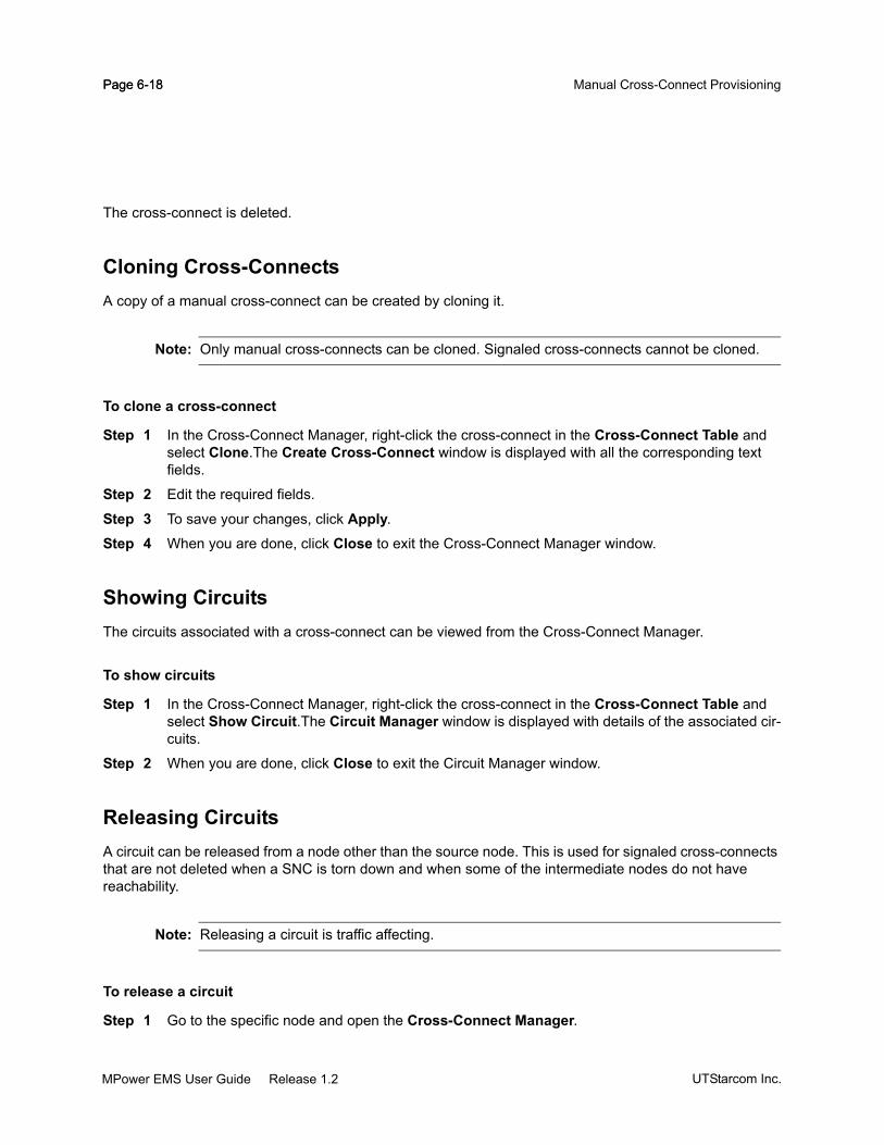
Page 6-18 Manual Cross-Connect ProvisioningPage 6-18
The cross-connect is deleted.
Cloning Cross-ConnectsA copy of a manual cross-connect can be created by cloning it.
Note: Only manual cross-connects can be cloned. Signaled cross-connects cannot be cloned.
To clone a cross-connect
Step 1 In the Cross-Connect Manager, right-click the cross-connect in the Cross-Connect Table and select Clone.The Create Cross-Connect window is displayed with all the corresponding text fields.
Step 2 Edit the required fields.
Step 3 To save your changes, click Apply.
Step 4 When you are done, click Close to exit the Cross-Connect Manager window.
Showing CircuitsThe circuits associated with a cross-connect can be viewed from the Cross-Connect Manager.
To show circuits
Step 1 In the Cross-Connect Manager, right-click the cross-connect in the Cross-Connect Table and select Show Circuit.The Circuit Manager window is displayed with details of the associated cir-cuits.
Step 2 When you are done, click Close to exit the Circuit Manager window.
Releasing CircuitsA circuit can be released from a node other than the source node. This is used for signaled cross-connects that are not deleted when a SNC is torn down and when some of the intermediate nodes do not have reachability.
Note: Releasing a circuit is traffic affecting.
To release a circuit
Step 1 Go to the specific node and open the Cross-Connect Manager.
UTStarcom Inc.MPower EMS User Guide Release 1.2

Page 6-19Service Provisioning
Step 2 In the Cross-Connect Manager, right-click the signaled cross-connect in the Cross-Connect Table and select Release Circuit.
Step 3 To save your changes, click Apply.
Step 4 When you are done, click Close to exit the Cross-Connect Manager window.
To release a signaled cross-connect
Note: Releasing a signaled cross-connect is service affecting.
Step 1 In the Equipment View, right-click the DLM and select Provisioning > Release Cross-Con-nect(Signaled). A Confirmation Message window appears.
Step 2 Click Yes to release the signaled cross-connect for valid and orphaned circuits through the selected DLM.
Show AlarmsThe alarms for a single cross-connect can be viewed. This allows for easier isolation of faults while troubleshooting.
To show alarms for a cross-connect
Step 1 Go to the specific node and open the Cross-Connect Manager.Step 2 In the Cross-Connect Manager, right-click the cross-connect in the Cross-Connect Table and
select Show Alarms. The Alarm Manager window is displayed.
Step 3 When you are done, click Close to exit the Alarm Manager window.
Viewing Source EquipmentInvoking the source equipment, shows the equipment resources used in creating an individual cross-connect.
To view the source equipment
Step 1 Go to the specific node and open the Cross-Connect Manager.Step 2 In the Cross-Connect Manager, right-click the cross-connect in the Cross-Connect Table and
select Source Equipment. The Equipment Manager window is displayed.
Step 3 When you are done, click Close to exit the Equipment Manager window.
MPower EMS User Guide Release 1.2UTStarcom Inc.

Page 6-20 Manual Cross-Connect ProvisioningPage 6-20
Viewing Source FacilityInvoking the source facility displays all facilities associated with the selected cross-connect.
To view the source facility
Step 1 Go to the specific node and open the Cross-Connect Manager.Step 2 In the Cross-Connect Manager, right-click the cross-connect in the Cross-Connect Table and
select Source Facility. The Facility Manager window is displayed.
Step 3 When you are done, click Close to exit the Facility Manager window.
UTStarcom Inc.MPower EMS User Guide Release 1.2

Page 6-21Service Provisioning
Dynamically Signaled SNC ProvisioningSee “Dynamically Signaled SNC Provisioning” on page 6-5 for an overview of this provisioning mode.
Circuit ManagerUse Circuit Manager to view, create, modify and delete circuits. You can perform the following procedures using this tool:
“To search for a circuit” on page 6-25
“To filter circuits” on page 6-25
“To create circuits” on page 6-23
“To view/modify circuit information” on page 6-25
“To modify routing constraints” on page 6-26
“To clone a circuit” on page 6-28
“To delete a circuit” on page 6-28
“To export a circuit” on page 6-29
“To show alarms for a circuit” on page 6-29
“To show cross-connects” on page 6-29
Creating CircuitsA circuit is created from the Create Circuit window invoked from the Circuit Manager window. Before creating a circuit, ensure that the following have been completed:
All equipment have been pre-configured. See “Pre-configuring Circuit Packs” on page 6-22.
The topology is up and running with GMPLS links and controls established. See “Configuring BMM GMPLS Links” on page 6-37.
To invoke the Circuit Manager
Step 1 Do one of the following:
In the MPower GNM Main Menu, select Provisioning > Circuit Manager. The Circuit Man-ager is displayed in the Workspace Area.
In the Equipment View, right-click the DLM/TAM/TOM circuit pack and select Provisioning > Circuit Manager.
Right-click a network element in the Equipment Tree and select Provisioning > Circuit Manager.
MPower EMS User Guide Release 1.2UTStarcom Inc.
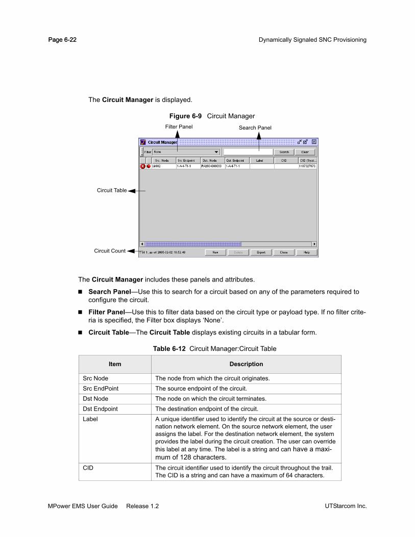
Page 6-22 Dynamically Signaled SNC ProvisioningPage 6-22
The Circuit Manager is displayed.
Figure 6-9 Circuit Manager
The Circuit Manager includes these panels and attributes.
Search Panel—Use this to search for a circuit based on any of the parameters required to configure the circuit.
Filter Panel—Use this to filter data based on the circuit type or payload type. If no filter crite-ria is specified, the Filter box displays ‘None’.
Circuit Table—The Circuit Table displays existing circuits in a tabular form.
Table 6-12 Circuit Manager:Circuit Table
Item Description
Src Node The node from which the circuit originates.
Src EndPoint The source endpoint of the circuit.
Dst Node The node on which the circuit terminates.
Dst Endpoint The destination endpoint of the circuit.
Label A unique identifier used to identify the circuit at the source or desti-nation network element. On the source network element, the user assigns the label. For the destination network element, the system provides the label during the circuit creation. The user can override this label at any time. The label is a string and can have a maxi-mum of 128 characters.
CID The circuit identifier used to identify the circuit throughout the trail. The CID is a string and can have a maximum of 64 characters.
Filter Panel Search Panel
Circuit Table
Circuit Count
UTStarcom Inc.MPower EMS User Guide Release 1.2

Page 6-23Service Provisioning
Circuit Count Panel—The Circuit Count panel displays the number of circuits displayed against the total number of circuits. The count of circuits displayed depends on the type of circuit selected in the Filter.
To create circuits
Step 1 Do one of the following:
From the MPower GNM Main Menu, select Provisioning > Circuit Manager. The Circuit Manager is displayed in the Workspace Area. Click New to create a new circuit.
From the MPower GNM Main Menu, Select Provisioning > Create Circuit.
In the Equipment View, right-click the DLM, TAM or TOM circuit pack and select Provision-ing > Create Circuit.
Right-click the network element in Equipment Tree and select Provisioning > Create Cir-cuit.
The Create Circuit window is displayed.
CID (System) The system generated circuit identifier used to identify the circuit throughout the trail.
Service/Rate The service type for which the circuit is created.
Location The location of the network element.
Admin State See “Administrative State” on page 6-2.
Oper State See “Operational State” on page 6-3.
Service State See “Service State” on page 6-3.
Fail Reason The reason for failure when the circuit is not successfully set up.
Table 6-12 Circuit Manager:Circuit Table
Item Description
MPower EMS User Guide Release 1.2UTStarcom Inc.

Page 6-24 Dynamically Signaled SNC ProvisioningPage 6-24
Figure 6-10 Create Circuit
Step 2 In the General panel, enter or select the following values:
Circuit ID (CID)—Circuit ID.
Label—Unique Identifier for the circuit.
Service—The service type provided.
The values can be one of OC192/10GbE WAN, STM-64, OC-48, STM-16, 10GbE LAN, 1GbE, 10G Clear Channel.
Pre-provisioned Capacity—Check box that allows the circuit to be configured with a mini-mum of pre-provisioned equipment.
Local DLM Route Only—Check box that allows local DLM route only.
Step 3 In the Endpoint panel, enter or select the following:
Source—The name of the network element where the source termination point is located. This is always the current node. To select the termination point for the circuit, click the [...] button and select the termination point from the table. This selection is needed only if the Create Circuit window is launched from the Main Menu.
Destination—The name of the network element where the destination termination point is located.
Step 3a Destination Node—Click the [...] button to select the network element. Navi-gate to the network element from the Destination Node tree structure and click Apply.
Step 4 In the Route Query panel, click Execute Query to find if a route exists to the destination. A list of matching termination points on the destination node will appear in the Result panel. If the route exists, the Current Route panel displays the list of current routes.
UTStarcom Inc.MPower EMS User Guide Release 1.2

Page 6-25Service Provisioning
Note: The Current Route panel displays the list of current routes only if the Overwrite Inclusion List checkbox is not checked.
Step 4a From the Result panel, select the endpoint that is required and click the Copy to Z-End button. The destination endpoint will appear in the Destination Endpoint field.
Step 5 In the States panel, select the Admin State and Alarm Reporting parameters from the drop-down menu.
Step 6 To save the changes, Click Apply.
Step 7 When you are done, click Close to exit the Manage Routing-Constraints window and return the control to the Create Circuit window.
The circuit that has just been created is updated in the Circuit Manager.
To search for a circuit
Enter the search string in the Search text box. The list of circuits matching this search criteria is dis-played in the Circuits Table.
Click Clear to clear the search criteria.
To filter circuits
Select the filter string from the Filter drop-down menu. The list of circuits matching this filter criteria is displayed in the Circuit Table.
Viewing and Modifying CircuitsA circuit can be viewed and modified from the Circuit Properties window. See “Creating Circuits” on page 6-21 for the description of the attributes.
To view/modify circuit information
Step 1 In the Circuit Manager, right-click the circuit in the Circuit Table and select Properties. The Cir-cuit Properties window is displayed.
MPower EMS User Guide Release 1.2UTStarcom Inc.

Page 6-26 Dynamically Signaled SNC ProvisioningPage 6-26
Figure 6-11 Circuit Properties
Step 2 Edit the fields as you did while creating the circuit. The fields that can be edited are: Label, Admin State and Alarm Reporting.
Step 3 To save your changes, click Apply.
Step 4 When you are done, click Close to exit the Circuit Properties window.
Modifying Routing ConstraintsRouting constraints can be modified when the circuit is in the locked state. The user can select or remove control links from the inclusion and exclusion list.
To modify routing constraints
Step 1 Change the Admin State of the circuit to Lock.
Step 2 Right click the circuit and select Properties > Routing Constraint. The Routing Constraints panel is displayed.
Step 3 In the Routing Constraints panel, select the node(s) or OSC and OCG links to be included or excluded in/from the circuit path. Perform this step if you want to limit the routes a circuit can travel.
UTStarcom Inc.MPower EMS User Guide Release 1.2

Page 6-27Service Provisioning
Figure 6-12 Routing Constraints
Step 4 To manage these parameters click Manage List. The Manage Routing-Constraints window is displayed.
Figure 6-13 Manage Routing-Constraints
Inclusion List—A dynamic list into which the user can add the nodes or control-links that must be included in the circuit path. The following attributes can be specified in the Inclusion List:
A node
Control-links. See “Configuring Links” on page 6-88 for information on how to configure control links.
Channel number. For OCG, specification of the channel / sub-channel number is manda-tory. Press the Return key after entering the channel / sub-channel number. For all 10G payloads such as OC192, STM64, 10GbE LAN and 10G Clear Channel, the channel number is of the format ‘x’, where ‘x’ can take any value between 1 and 10. For all 2.5 G payloads such as OC48, STM16 and 1GbE, the channel number is of the format ‘x-y’, where ‘x’ can take any value between 1 and 10; ‘y’ can take any value between 1 and 4.
MPower EMS User Guide Release 1.2UTStarcom Inc.

Page 6-28 Dynamically Signaled SNC ProvisioningPage 6-28
Exclusion List—A dynamic list into which the user can add the nodes and GMPLS links that must be excluded from the circuit path. The following attributes can be specified in the Exclu-sion List:
A node
Control-links. See “Configuring Links” on page 6-88 for information on how to configure Control Links.
Note: OCG can be included in the inclusion list, but cannot be included in the exclusion list.
Note: The order in which the node and its links are specified is very important since all routing takes place in the order specified in the Inclusion List.
Step 5 To save your changes, click Apply.Step 6 When you are done, click Close to exit the Circuit Properties window.
Cloning CircuitsA copy of a circuit can be created by cloning it.
To clone a circuit
Step 1 In the Circuit Manager, right-click the circuit in the Circuit table and select Clone. The Create Circuit window is displayed with all the fields displayed in the corresponding text fields.
Step 2 Edit the required fields, to create a new circuit.
Step 3 To save your changes, click Apply.
Step 4 When you are done, click Close to exit the Circuit Manager window.
Deleting CircuitsA circuit can be deleted if it is not going to be used.
Note: Circuit deletion is allowed only if it is in the ‘Administrative Locked’ or ‘Administrative Main-tenance’ state.
To delete a circuit
Step 1 In the Circuit Manager, select the circuit and do one of the following:
Right-click and select Delete.
UTStarcom Inc.MPower EMS User Guide Release 1.2

Page 6-29Service Provisioning
Select a row and click Delete.
You are prompted by a message to confirm the deletion.
Step 2 Confirm the deletion. The circuit is deleted.
Exporting CircuitsA circuit can be exported from the Properties window.
To export a circuit
Step 1 In the Circuit Manager, filter the circuit in the Circuit table and click Export. The Save window is displayed.
Step 2 Enter the required path and the filename. Select the file type.
Step 3 To export, click Save.
Step 4 When you are done, click Cancel to close the Properties window.
Note: Only those circuits that are displayed in the current view of the Circuit Manager will be exported.
Show AlarmsThe alarms for a single circuit can be viewed. This allows for easier isolation of faults while troubleshooting.
To show alarms for a circuit
Step 1 In the Circuit Manager, right-click the circuit in the Circuit Table and select Show Alarms. The Alarm Manager window is displayed.
Step 2 When you are done, click Close to exit the Alarm Manager window.
Show Cross-connects
To show cross-connects
The cross-connects associated with a circuit can be viewed.
Step 1 In the Circuit Manager, right-click the circuit in the Circuit Table and select Show Cross-Con-nects.
Select Matching System CID to view the Cross-Connect Manager that displays cross-con-nects with a matching system CID.
MPower EMS User Guide Release 1.2UTStarcom Inc.

Page 6-30 Dynamically Signaled SNC ProvisioningPage 6-30
Select Matching Customer CID to view the Cross-Connect Manager that displays cross-connects with a matching customer CID.
Step 2 When you are done, click Close to exit the Cross-Connect Manager window.
Step 3
UTStarcom Inc.MPower EMS User Guide Release 1.2

Page 6-31Service Provisioning
Protection Group ManagerUse Protection Group Manager tool to view, create, lockout, clear lockout, manual switch or delete protection groups.
To invoke the Protection Group Manager
Do one of the following:
From the MPower GNM Main Menu, select Provisioning > Protection Group Manager.
In the Equipment View, right-click the TOM circuit pack and choose Protection Group Manager.
In the Facility Manager, right-click the Trib and choose Protection Group Manager.
The Protection Group Manager window is displayed.
Note: Protection group manager is available for digital nodes only.
Figure 6-14 Protection Group Manager
The Protection Group Manager window includes these panels and attributes:
Search Panel—Use this to search for a protection group based on any of the parameters required to configure the protection group.
Filter Panel—Use the filter panel to filter data based on the protection group parameters. If no filter criteria is specified, the Filter box displays ‘None’.
MPower EMS User Guide Release 1.2UTStarcom Inc.

Page 6-32 Protection Group ManagerPage 6-32
Protection Group Table—The Protection Group Table displays existing protection groups in a tabular form.
Table 6-13 Protection Group Manager:Protection Group Table
Item Description
Node The network element identifier.
PG Name Name of the Protection Group. This is an optional parameter.
Label Unique identifier used to identify the circuit. This is an optional parameter.
PU#1 (Protection Unit # 1)
AID The termination point for PU#1. This is the Trib port AID.State Indicates the actual and preferred states of the PU#1.
It is represented as actual state (preferred state).
The value of actual state can be one of the following:
Act—Active
HotStby—Hot standby
ColdStby—Cold standby
Unknown—Unknown
The value of preferred state is one of:
Wrk—Working
Prot—Protection
PS Req Protection Switch Request Status indicates the current state of the PU from the data plane perspective. This is a read-only attribute. It indicates if a PS Request, other than Manual Switch is currently in effect on the PU.
Valid values can be one of the following:
• Outstanding—This is denoted by a *.
• None—This is denoted by a blank space.
PU#2 (Protection Unit # 2)
AID The termination point for PU#2. This is the Trib port AID.
UTStarcom Inc.MPower EMS User Guide Release 1.2

Page 6-33Service Provisioning
To invoke Protection Group Properties window
In the Protection Group Table, right-click a protection group and select Properties.
The Protection Group Properties:PG Name window is displayed.
Figure 6-15 Protection Group Properties
The Protection Group Properties:PG Name window includes these panels and attributes:
State Indicates the actual and preferred states of the PU#2.
It is represented as actual state (preferred state).
The value of actual state can be one of the following:
Act—Active
HotStby—Hot standby
ColdStby—Cold standby
Unknown—Unknown
The value of preferred state is one of the following:
Wrk—Working
Prot—Protection
PS Req Protection Switch Request Status indicates the current state of the PU from the data plane perspective. This is a read-only attribute. It indicates if a PS Request, other than Manual Switch is currently in effect on the PU.
Valid values can be one of the following:
• Outstanding—This is denoted by a *.
• None—This is denoted by a blank space.
Table 6-13 Protection Group Manager:Protection Group Table
Item Description
MPower EMS User Guide Release 1.2UTStarcom Inc.

Page 6-34 Protection Group ManagerPage 6-34
Summary—The summary panel includes these attributes:
Manage Protection Units—The Manage Protection Units panel displays all the available Trib ports. It includes these attributes:
Preferred Working—This is the preferred working protection unit. This value can be set only during creation.
Creating Protection GroupsTwo Trib ports are required for the creation of a protection group.
Following are the criteria for two Trib ports to be part of a protection group:
Table 6-14 Create Protection Group: Summary Panel
Item Description
Node The network element identifier.
Label Unique identifier used to identify the circuit. The label can have up to 128 characters.
Protection Group Name Name of the protection group. This is an optional parameter. It can not be modified after creation. The Protection Group Name can have up to 32 characters.
Table 6-15 Create Protection Group: Manage Protection Units Panel
Item Description
AID The termination point for the protection group.
Configured State The preferred state of the protection unit.
Valid values can be one of the following:
Wrk —Working.
Prot —Protection.
Standby Status The actual state of the protection unit.
Valid values can be one of the following:
Act—Active.
HotStby—Hot standby.
ColdStby—Cold standby.
Unknown—Unknown.
PS Req See Table 6-13 on page 6-32. Here, ‘yes’ is displayed in the place of *.
Lockout Indicates the Lockout status of the protection unit.
UTStarcom Inc.MPower EMS User Guide Release 1.2

Page 6-35Service Provisioning
Should be part of signaled SNCs.
Should be part of manual cross-connect.
Should be present on the same chassis
Should have the same service type.
Should not be part of a PG already.
To create a protection group
Step 1 Do one of the following
From the MPower GNM Main Menu, select Provisioning > Create Protection Group...
In the Equipment View, right-click the TOM circuit pack and choose Create Protection Group....
In the Cross-Connect Manager, right-click the cross-connect and choose Create Protection Group....
In the Facility Manager, right-click the Trib and choose Create Protection Group.
The Create TribY-cable Protection window is displayed.
Note: Node selection is available only from MPower GNM Main Menu.
Step 2 Select the required node. Click Add. The Select Protection Unit window is displayed. The pro-tection units which are already part of a protection group are not shown.
Step 3 Select the required PU#1 and click Ok. The Create TribY-cable Protection window is displayed.
Step 4 Click Add. The Select Protection Unit window is displayed. Only protection units that match the service type of PU#1 are shown.
Step 5 Select the required PU#2 and click Ok. The Create TribY-cable Protection window is displayed.
Step 6 Select the preferred working protection unit.
Step 7 To save your changes, click Ok.
MPower EMS User Guide Release 1.2UTStarcom Inc.

Page 6-36 Protection Group ManagerPage 6-36
Figure 6-16 Create Protection Group
The Create TribY-cable Protection window contains the following attributes.
Summary—See Table 6-14 on page 6-34 for a description of the parameters.
Manage Protection Units—See Table 6-14 on page 6-34 for a description of the parameters.
Preferred Working—Select the preferred working protection unit, from the drop-down menu. This value can be set only during creation.
Add—Add a protection unit to the protection group.
Remove—Remove a protection unit from the protection group.
Lockout of Working/ProtectionUsers can perform a lockout of the working or the protection path.
To perform a lockout of Working/Protection
Step 1 In the Protection Group Manager window, right-click a protection group in the protection group table.
Step 2 Select Lockout Working to lockout the working path. Select Lockout Protection to lockout the protection path.
Step 3 A Confirm Message window is displayed. Click Continue to perform the lockout. Click Aban-don if you do not want to perform a lockout.
Step 4 When you are done, click Close to close the Protection Group Manager window.
Note: Lockout operation may impact the traffic on the protection units.
Clear Lockout of Working/ProtectionUsers can clear the lockout on the working or protection path.
UTStarcom Inc.MPower EMS User Guide Release 1.2

Page 6-37Service Provisioning
To Clear Lockout of Working/Protection
Step 1 In the Protection Group Manager window, right-click a protection group in the protection Group table.
Step 2 Select Clear Working Lockout to lockout the working path. Select Clear Protection Lockout to lockout the protection path.
Step 3 When you are done, click Close to close the Protection Group Manager window.
Validation may fail under the following conditions:
Both the remote Trib ports are part of different protection groups.
One of the remote Trib ports is part of a protection group.
Remote Trib ports are not part of any protection group, but they are on different chassis.
Manual SwitchUsers can perform a manual switch of the protection unit from or to the Act state if the value of Protection Switch Request Status is None.
Note: Performing a manual switch may impact traffic.
To perform a manual switch
In the Protection Group Table, right-click a protection group and choose Manual Switch.
A successful manual switch operation is indicated by a Manual Switch operation success-ful in the status bar.
Show AlarmsUsers can view the alarms on the protection group, Trib ports, client ports, DTPCTP, DLM, TAM and TOM.
To view alarms on the protection group
In the Protection Group Table, right-click a protection group and choose Show Alarms.
The Alarm Manager window displays the current alarms.
Show CircuitUsers can view the circuits of both Tribs.
MPower EMS User Guide Release 1.2UTStarcom Inc.

Page 6-38 Protection Group ManagerPage 6-38
To view circuits on the protection group
In the Protection Group Table, right-click a protection group and choose Show Circuit.
The Circuit Manager window displays the circuits.
Show FacilitiesUsers can view the facilities such as Trib ports, client ports and DTPCTP.
To view facilities on the protection group
In the Protection Group Table, right-click a protection group and choose Show Facilities.
The Facility Manager window is displayed.
To view Trib alarms, right-click a Trib port in the Facility Manager window and select Show Alarms.
The Alarm Manager window displays the Trib alarms.
Show Cross-Connects
To view cross-connects on the protection group
In the Protection Group Table, right-click a protection group and choose Show Cross-Connects.
The Cross-Connect Manager window is displayed.
Delete a Protection GroupUsers can delete a protection group if the following conditions are satisfied:
One of its Trib ports is in Administrative Locked state.
Trib Disable Action is set to Disable Laser (LOL).
Refer “Configuring TOM Trib Port Termination Point” on page 6-54 for a description of the above mentioned conditions.
To delete a protection group
Step 1 In the Protection Group Table, right-click a protection group and choose Delete. A Confirm Mes-sage window is displayed. The window displayed is as shown in Figure 6-17.
Step 2 Click Cancel to cancel deletion.
Step 3 Click Delete PG to confirm deletion. The protection group is successfully deleted if the above mentioned conditions are satisfied. If the conditions are not satisfied, an error message is dis-played.
UTStarcom Inc.MPower EMS User Guide Release 1.2

Page 6-39Service Provisioning
Figure 6-17 Delete Protection Group:Confirm Message
MPower EMS User Guide Release 1.2UTStarcom Inc.

Page 6-40 Protection Group ManagerPage 6-40
UTStarcom Inc.MPower EMS User Guide Release 1.2

CHAPTER 7
Performance Monitoring
This chapter explains how to handle performance monitoring (PM) in the following sections:
“Overview” on page 7-2
“Retrieving PM Data” on page 7-3
“Uploading PM Data” on page 7-5
“Configuring Thresholds” on page 7-11
Note: This chapter describes the user-driven actions used to view PM statistics and does not con-tain descriptions of the attributes. Refer to the UTStarcom TN780 System Description man-ual for more information.
MPower GNM User Guide Release 1.2UTStarcom Inc.

Page 7-2 OverviewPage 7-2
OverviewUTStarcom TN780 and Optical Line Amplifier network elements provide extensive performance monitoring to provide early detection of service degradation before service outage occurs. The performance monitoring capabilities allow customers to pro-actively detect problems and correct them before end-user complaints are registered. Performance monitoring is also needed to ensure contractual Service Level Agreements between the customer and the end-user.
MPower GNM lets you view and manage the PM data collected by the network elements. For a description of PM parameters, thresholds and their default values, see Appendix A: “TN780 PM Parameters“. MPower GNM provides the following performance monitoring capabilities:
View real-time PM data.
View 15-minute historical PM data. The network element maintains current 15-minute and ninety-six previous 15-minute digital PM data counters and optical PM data gauges.
View 24-hour historical PM data. The network element maintains current 24-hour and seven previ-ous 24-hour digital PM data counters and optical PM data gauges.
Reset the current 15-min and 24-hour historical counters per managed object. On reset, the current counters are marked invalid.
The invalid or suspect PM interval is shown with a red background.
Configure the refresh interval to automatically update the monitored PM data.
Each user session is provided a local accumulator for each real-time PM counter supported. The local counter is incremented from the time user session is activated. You can reset the local counter at any time.
Configure PM thresholds and enable or disable PM threshold reporting by the network element.
Enable or disable PM collection in the network element.
Export PM data, manually or periodically, in CSV file format to the user specified external server.
For a detailed description of the performance monitoring features supported by the network element, refer to the UTStarcom TN780 System Description document.
UTStarcom Inc.MPower GNM User Guide Release 1.2

Page 7-3Performance Monitoring
Retrieving PM DataMake sure the PM data collection is enabled for a given managed object on the network element. See “Enabling PM Data Collection” on page 7-3.
Enabling PM Data CollectionPM data is collected on all equipment by default. MPower GNM provides an option to enable or disable the collection of PM data.
To enable PM data
Step 1 Select the desired equipment in the Equipment Tree or the Equipment View.
Step 2 Right-click and select the termination point for which you want the PM data to be collected. The Equipment Properties window is displayed.
Step 3 Click Enable PM Collection checkbox in the <Equipment> Properties window. The location of the Enable PM Collection checkbox is dependent on the termination point. See CHAPTER 6: “Equipment and Termination Point Management“ for more details.
Retrieving Historical PM DataThe historical PM data is viewed from the Properties dialog box of the termination point.
To view PM data for a single equipment
Step 1 Select the desired equipment in the Equipment Tree or the Equipment View.
Step 2 Right-click and select the termination point for which you want to view the PM data. The <Termi-nation Point> Properties window is displayed.
Step 3 Select the tab for which you would like to view the performance data like 15Min History, or 24Hour History, RealTime PM, etc.
Step 4 Click Close to close the window.
Retrieving Real Time PM DataThe real-time PM data is viewed from the Properties dialog box of the termination point.
To view PM data for a single equipment
Step 1 Select the desired equipment in the Equipment Tree or the Equipment View.
MPower GNM User Guide Release 1.2UTStarcom Inc.

Page 7-4 Retrieving PM DataPage 7-4
Step 2 Right-click and choose the termination point for which you want to view the PM data. The <Ter-mination Point> Properties window is displayed.
Step 3 Select the RealTime PM tab to view the data.
Step 4 Click Close to close the window.
Re-setting PM countersYou can reset the current 15-minute and 24-hour PM data counters. Use the Reset button to reset PM counters.
To reset the PM counter
Step 1 In the Equipment View or the Equipment Tree, select the desired equipment.
Step 2 Right-click and choose the termination point for which you want to reset the PM data. The <Ter-mination Point> Properties window is displayed.
Step 3 Select 15Min History tab or 24Hour History tab as desired.
Step 4 Click Reset. The PM counters are reset in the network element.
Step 5 If you are done, click Close exit the window.
Note: When you click reset, all PM counters for the current interval corresponding to the selected termination are marked invalid.
Refreshing PM dataMPower GNM provides the Refresh Interval option to set time intervals for refreshing the displayed PM data.
To set automatic PM data refresh
Step 1 In the Equipment View or the Equipment Tree, select the desired equipment.
Step 2 Right-click and choose the termination point for which you want to reset the PM data. The <Ter-mination Point> Properties window is displayed.
Step 3 Select the tab for which you would like to view the performance data like 15Min History, or 24Hour History, C-Band RealTime PM, etc.
Step 4 Click Refresh Interval and select the desired interval from the drop-down menu. The PM data in the <Termination Point> Properties window is automatically updated at the configured inter-val. Click Refresh PM at any time, to manually refresh the PM data.
Step 5 If you are done, click Close exit the window.
UTStarcom Inc.MPower GNM User Guide Release 1.2

Page 7-5Performance Monitoring
Uploading PM DataUse the PM Upload Schedule window to archive the PM data collected by the network element. Use any of these methods to upload the data:
Manual—Use the manual mode to immediately upload the PM data to the specified FTP server.
Scheduled—Use scheduled upload to automatically upload the data at regular intervals, hourly, every 4hours, every 8 hours or every 12 hours as configured.
You can specify the primary and secondary FTP server to store the archived PM data. By default, the PM data is uploaded to the primary server. However, if that server is not available, the PM data is uploaded to the secondary server. The file name is generated automatically using the format pm24hr_%D.csv or pm15min_%D.csv where %D represents the date and time of transfer. It is of the form “YYYYMMDDhhmmss”.
Note: It is possible that the PM data files from multiple network elements stored in the same direc-tory on the server may overwrite each other. Hence, when configuring the PM data upload, assign each network element a different FTP server target directory. Alternatively, append the network element’s node name to the PM data upload file name.
To invoke PM Upload Scheduler
Step 1 Log into the MPower GNM with network administrator privilege.
Step 2 Select Tools > PM Upload Scheduler. The PM Upload Scheduler window is displayed.
The PM Upload scheduler window includes these panels and attributes:
MPower GNM User Guide Release 1.2UTStarcom Inc.

Page 7-6 Uploading PM DataPage 7-6
Figure 7-1 PM Upload Scheduler
Enable FTP Transfers
FTP Setup
Table 7-1 Enable FTP Transfers Panel
Item Description
15 Min PM The PM data is collected for 15 minute time intervals. Only if this is checked, the filename and upload schedule can be configured.
24 HR PM The PM data is collected for 24 hour time intervals. Only if this is checked, the filename and upload schedule can be configured.
Table 7-2 FTP Setup Panel
Item Description
Primary FTP ServerIP Address The IP address of the primary server for file transfer. The primary IP server must
be in the same signaling domain. If the connection to the primary server fails an alarm with severity Warning is generated and the connection is established to the secondary server.
User Name The login name on the primary server for FTP connection. The account user must have all access privileges in order that the transfer be successful.
UTStarcom Inc.MPower GNM User Guide Release 1.2

Page 7-7Performance Monitoring
File Name/Path
Password The password for the corresponding login name. The password can be set from this dialog box.
Secondary FTP ServerIP Address The IP address of the secondary server for file transfer. The secondary IP
server must be in the same signalling domain. If the connection to the second-ary server fails, an alarm with severity Major is generated.
User Name The login name on the Secondary server for FTP connection.
Password The password for the corresponding login name.
Table 7-3 File Name/Path Panel
Item Description
15 Min PMPath The location on the primary or secondary server to which the file will be
transferred. If no server path is specified, files are transferred to the home directory.
Name Format The name of the file that is uploaded or downloaded. This filename is a pre-defined static file or is a name that is computed by the network element. The filename is of the format pm15min_%D where %D represents the date and time of transfer. It is of the form “YYYYMMDDhhmmss”.
24 Hr PMPath The location on the primary or secondary server to which the file will be
transferred. If now server path is specified, files are transferred to the home directory.
Name Format The name of the file that is uploaded/downloaded. This filename is a pre-defined static file or is a name that is computed by the network element. The filename is of the format pm24hr_%D where %D represents the date and time of transfer. It is of the form “YYYYMMDDhhmmss”.
Table 7-2 FTP Setup Panel
Item Description
MPower GNM User Guide Release 1.2UTStarcom Inc.

Page 7-8 Uploading PM DataPage 7-8
Upload Schedule
Current/Last Attempt Details
Table 7-4 Upload Schedule Panel
Item Description
15 Min PM The time interval at which the 15 Minute PM upload is triggered. The drop-down menu is enabled only when the 15 Min PM check box is selected in the Enable FTP Transfers panel. PM data can be uploaded in the following ways:
• Not Scheduled—15 Min PM data is never uploaded to the FTP server
• Every 12 Hours—15 Min PM data is uploaded every 12 hours
• Every 8 Hours—15 Min PM data is uploaded every 8 hours
• Every 4 Hours—15 Min PM data is uploaded every 4 hours
• Every Hour—15 Min PM data is uploaded every 1 hour
• Upload Now—15 Min PM data is uploaded immediately.
24 Hr PM The time interval at which the 24 Hour PM upload is triggered. The drop-down menu is enabled only when the 24 Hour PM check box is selected in the Enable FTP Transfers panel. PM data can be uploaded in the following ways:
• Not Scheduled—24 Hour PM data is never uploaded to the FTP server
• Daily—24 Hour PM data is uploaded every day
... If you selected daily back up, click this to set the date and time at which daily backups are scheduled.
In order to prevent all network elements from transferring the PM data files at the same time, MPower GNM starts the transfer at xfrScheduleOffset sec-onds after the configured date and time. The xfrScheduleOffset value ranges from 0 to 300secs and its value derived randomly in each network element.
If the upload interval is not scheduled, the xfrScheduleOffset value shows ‘0’.
Table 7-5 Current/Last Attempt Details Panel
Item Description
15 Min PMCurrent TransferStatus The Status of the 15 Min PM data transfer. This is a read-only field provided by
the network element.
Progress The latest status of the 15 Min PM data transfer.
Last AttemptedAt The date and time at which the last 15 Min PM data transfer was initiated.
UTStarcom Inc.MPower GNM User Guide Release 1.2

Page 7-9Performance Monitoring
Last Successful Upload
To schedule PM data collection
Step 1 Invoke PM Upload Scheduler using the procedure described in “To invoke PM Upload Sched-uler” on page 7-5.
Status (Primary) The result of the last attempted 15 Min PM data transfer to the primary FTP server. This is a read-only field provided by the network element.
Status (Secondary) The result of the last attempted 15 Min PM data transfer to the secondary FTP server. This is a read-only field provided by the network element.
24 Hr PMCurrent TransferStatus The status of the 24 Hr PM data transfer. This is a read-only field provided by
the network element.
Progress The latest status of the 24 Hr PM data transfer.
Last AttemptedAt The data and time at which the last 24 Hr PM data transfer was initiated.
Status (Primary) The result of the last attempted 24 Hr PM data transfer to the primary FTP server. This is a read-only field provided by the network element.
Status (Secondary) The result of the last attempted 24 Hr PM data transfer to the secondary FTP server. This is a read-only field provided by the network element.
Table 7-6 Last Successful Upload Panel
Item Description
15 Min PMAt The most recent time at which the 15 Min PM data was successfully
uploaded.
On The most recent date on which the 15 Min PM data was successfully uploaded.
File The name of the 15 Min PM data file that was successfully uploaded to the FTP server.
24 Hr PMAt The most recent time at which the 24 Hr PM data was successfully uploaded.
On The most recent date on which the 24 Hr PM data was successfully uploaded.
File The name of the 24 Hr PM data file that was successfully uploaded to the FTP server.
Table 7-5 Current/Last Attempt Details Panel
Item Description
MPower GNM User Guide Release 1.2UTStarcom Inc.

Page 7-10 Uploading PM DataPage 7-10
Step 2 Enter the required parameters to schedule the PM data collection.
Step 3 To save your changes, click Apply.
Step 4 When you are done, click Close to exit the PM Upload Scheduler window.
UTStarcom Inc.MPower GNM User Guide Release 1.2

Page 7-11Performance Monitoring
Configuring ThresholdsUTStarcom TN780 and Optical Line Amplifier network elements support thresholding which provides an early detection of faults before significant effects are felt by the end users. Degradation of service is detected by monitoring error rates. Threshold mechanisms on counters and gauges allow the detection of such trends and provide a warning to users when the error rate becomes high.
MPower GNM lets you configure the thresholds and also enable or disable threshold crossing alarms and events. For the description of the PM thresholds and their default values, see Appendix A: “TN780 PM Parameters“.
Thresholds can be set for the following termination points:
BMM Span. See “Span Threshold” on page 7-11.
DLM Optical Channel. See “Optical Channel Threshold” on page 7-12.
TOM Trib DTF Path. See “Trib DTF Path Threshold” on page 7-13.
TOM Trib Port. See “Client Trib Threshold” on page 7-14.
Span ThresholdThe Optical Span Loss is configured for the BMM circuit pack. If these threshold values are crossed TCCs are raised (if TCC reporting is enabled). The parameters set are:
Threshold High
Threshold Low
Maximum Engineering Span Loss
To configure Span thresholds
Step 1 In the Equipment View, right-click the BMM image and select Span.... The Span Properties window is displayed.
MPower GNM User Guide Release 1.2UTStarcom Inc.

Page 7-12 Configuring ThresholdsPage 7-12
Figure 7-2 Span Properties
Step 2 Go to the Span/C-Band tab. Enter the following values in the Threshold panel:
High
Low
Eng Span Loss (ESL)
Step 3 If TCCs are to be reported, select Enable check box for:
High/Low Reporting
Step 4 To save your changes, click Apply.
Step 5 When you are done, click Close to exit the Span Properties window.
Optical Channel ThresholdThe Optical Channel Threshold is configured from the DLM Optical Channel Properties window.
To configure an Optical Channel threshold
Step 1 In the Equipment View, right-click the DLM image and select Optical Channels.... The Optical Channel Properties window is displayed.
Step 2 Select an Optical Channel from the list.
Step 3 Go to the PM Configuration tab.
UTStarcom Inc.MPower GNM User Guide Release 1.2

Page 7-13Performance Monitoring
Figure 7-3 Optical Channel:PM Configuration
Step 4 In the DTF Section Threshold panel, enter the following values for 15 Minute or 24 Hr time intervals:
CV
ES
SES
Step 5 Check the relevant box if TCC are to be reported.
Step 6 To save your changes, click Apply.
Step 7 Repeat Steps 2 through 5 for every channel in the OCG.
Step 8 When you are done, click Close to exit the Optical Channel Properties window.
Trib DTF Path ThresholdThe DTF Section Threshold is set from the TOM circuit pack’s DTF Path Properties window. The following parameters are set:
CV
ES
SES
UAS
To configure Trib DTF Path threshold
Step 1 In the Equipment View, right-click the TOM image and select Trib DTF Path. The DTF Path Properties window is displayed.
Step 2 Go to the PM Configuration tab.
MPower GNM User Guide Release 1.2UTStarcom Inc.

Page 7-14 Configuring ThresholdsPage 7-14
Figure 7-4 DTF Path:PM Configuration
Step 3 In the DTF Path Threshold panel, enter the following values for 15 Minute or 24 Hr time inter-vals:
CV
ES
SES
UAS
Step 4 Select the relevant check boxes if TCCs are to be reported.
Step 5 To save your changes, click Apply.
Step 6 When you are done, click Close to exit the DTF Path Properties window.
Client Trib ThresholdThe SONET Client Threshold are set from the SONET Client Properties window.
To configure SONET Client threshold
Step 1 In the Equipment View, right-click the TOM image and select Client Trib termination point. The SONET Client Properties window is displayed.
Step 2 Go to the Rx Threshold tab.
UTStarcom Inc.MPower GNM User Guide Release 1.2

Page 7-15Performance Monitoring
Figure 7-5 SONET Client:Rx Threshold
Step 3 Enter the following values for 15 Minute or 24 Hr time intervals:
CV
ES
SES
SEFS
Step 4 Check the relevant box if TCC are to be reported.
Step 5 Go to the Tx Threshold tab. Enter the following values for 15 Minute and 24 Hour intervals:
CV
ES
SES
SEFS
Step 6 Go to the Diagnostics tab and check Enable PM Collection.
Step 7 To save your changes, click Apply.
Step 8 When you are done, click Close to exit the SONET Client Properties window.
MPower GNM User Guide Release 1.2UTStarcom Inc.

Page 7-16 Configuring ThresholdsPage 7-16
UTStarcom Inc.MPower GNM User Guide Release 1.2

CHAPTER 8
Environmental Alarms and Control
Environmental alarms are those triggered by an abnormal condition at the network element site. The network elements support input and output alarm contacts to monitor and control the customer’s equipment. Alarm input contacts allow you to connect external equipment (reactors), such as fire, alarm detector, high temperature detector, door open, and so on, to the network element. When the connected equipment triggers an input contact point, it raises an alarm with an alarm message and severity as configured by the user. Alarm output contacts allow you to connect external equipment to the network element. The network element can trigger the operation of the connected external equipment. Refer to the UTStarcom TN780 System Description manual for a description of the contacts provided by the network elements.
Additionally, the network elements support Alarm Cutoff (ACO) to mute the current audible alarms. This chapter describes procedures to configure alarm input contacts, alarm output contacts, and to enable the Alarm Cutoff in the following sections:
“Configuring Input Alarm Contacts” on page 8-2
“Configuring Output Alarm Contacts” on page 8-4
“Alarm Cutoff” on page 8-6
MPower EMS User Guide Release 1.2UTStarcom Inc.

Page 8-2 Configuring Input Alarm ContactsPage 8-2
Configuring Input Alarm ContactsThe TN780 and Optical Line Amplifier support sixteen user-configurable input contacts. Users can configure these input contacts which when activated, result in the generation of a customized alarm. The contacts can be configured from the Alarm Input Contacts Properties window.
Note: Though the hardware supports nineteen input alarm contacts, contacts 17, 18 and 19 are not being supported in Release 1.2.
Figure 8-1 Configure Input Alarm Contacts
The Alarm Input Contacts Properties window is divided into the panels as described below:
Input Alarm Contact Table
Table 8-1 Input Alarm Contact Table
Item Description
Label Assign an identifier, a character string with a maximum of 128 characters, to the input contact.
Contact Unique identifier assigned to the input contact.
UTStarcom Inc.MPower EMS User Guide Release 1.2

Page 8-3Environmental Alarms and Control
Configurable Parameters Panel—Fields in this panel are displayed only if a corresponding selec-tion is made in the Input Alarm Contact Table.
To configure input alarm contacts
Step 1 In the Equipment View, right-click just below the title bar (next to the ACO-OFF button) and select Alarm Input Contacts. The Alarm Input Contact Properties window is displayed.
Step 2 Select the input alarm contact that you want to configure in the Input Alarm Contact Table. The configurable parameters are displayed.
Step 3 Enter and edit the values.
Step 4 To save your changes, click Apply.
Step 5 Repeat Step 2 through Step 4 for each additional input contact.
Step 6 When you are done, click Close to exit the Alarm Input Contact Properties window.
Probable Cause Mes-sage
The probable cause to be used in the alarm report when an alarm input is triggered by the external equipment. Users can give meaningful causes depending on the connected external equipment. The Probable Cause Message is a string and can have a maximum of 128 characters.
Enabled Flag that specifies if the input closure contact is enabled via management interface like GNM. The value can be either True or False.
Severity The severity of the alarm. Can be one of critical, major, minor, informational or indeterminate. Once the severity for the alarm has been assigned, it can-not be modified using the Alarm Severity Assignment Profile. See “Fault Management” on page 5-1 for more information on alarm severities.
Normal Position This is a user-defined field that specifies the position of the input contact under normal condition. If the input contact position is different from the normal position, an alarm is reported for this input contact. The value can be one of NormalyClosed or NormallyOpen.
Current Position Current position of the input contact. Valid values can be one of Open or Closed.
Alarm Type The type of alarm displayed.
Table 8-1 Input Alarm Contact Table
Item Description
MPower EMS User Guide Release 1.2UTStarcom Inc.

Page 8-4 Configuring Output Alarm ContactsPage 8-4
Configuring Output Alarm ContactsThe TN780 and Optical Line Amplifiers support ten user-configurable output contacts. Each output has the following contacts:
NO (normally open)
NC (normally closed)
CM (common)
Under normal conditions, the NO output is open and the NC output is closed. When the output contact is enabled, the NO output is closed and the NC output is opened. Users can enable or disable (normal condition) the output contacts either manually or automatically on occurrence of a user-defined alarm condition. The Alarm Output Properties window is used to manually control the output contacts or set the trigger for the automatic operation.
Figure 8-2 Configure Output Alarm Contacts
The Alarm Output Contacts Properties window is divided into the panels as described below:
Output Alarm Contact Table
Table 8-2 Output Alarm Contact Table
Item Description
Label User defined identifier used to identify the output alarm closure contact.
Contact Unique identifier assigned to each output contact.
Description An alarm with this probable cause triggers the output contacts if the operation mode is set to Automatic.
UTStarcom Inc.MPower EMS User Guide Release 1.2

Page 8-5Environmental Alarms and Control
Configurable Parameters Panel — Fields in this panel are displayed only if a selection is made in the Output Alarm Contact Table.
To configure output alarm contacts
Step 1 In the Equipment View, right-click just below the title bar (next to the ACO-OFF button) and select Alarm Output Contacts. The Alarm Output Contacts Properties window is displayed.
Step 2 Select the alarm contact you want to edit in the Output Alarm Contact table.
Step 3 Enter and edit the values.
Step 4 To save your changes, click Apply.
Step 5 Repeat Step 2 through Step 4 for each additional output contact.
Step 6 When you are done, click Close to exit the Alarm Output Contact Properties window.
Operation Mode The operational mode of operation. Valid values can be one of the following:
• MAN_ON—Manual on. The output contact is enabled. NO output is closed and NC output is opened.
• MAN_OFF—Manual off. The output contact is disabled. NO is opened and NC is closed.
• Automatic—The output contact is automatically enabled or disabled when an alarm with the configured probable cause is raised/cleared.
Current Current position of the equipment. Valid values can be one of Open or Closed.
Table 8-2 Output Alarm Contact Table
Item Description
MPower EMS User Guide Release 1.2UTStarcom Inc.

Page 8-6 Alarm CutoffPage 8-6
Alarm Cutoff The Digital Optical Network system provides a feature to acknowledge an alarm condition and turn off the audible indicator. The ACO push button is used to mute the current audible alarms. Users can manually operate the ACO button located on the chassis or operate it remotely through the GNM interface. When the ACO is enabled, all outstanding audio alarms are turned off and the ACO LED on the I/O panel is lit. The ACO LED indicates that one or more audible alarms are present, but the audible indicators have been suppressed. The ACO LED is turned off when the silenced audible alarms are cleared. The alarm acknowledgment by the user does not change the ACO LED state.
Note: The ACO LED state is not shown in the GNM user interface.
Enabling ACO
To set ACO to OFF
Step 1 In the Equipment View, right-click just below the title bar (next to the ACO-OFF/ACO-ON but-ton) and select ACO State > ON. A Warning Message is displayed prompting the user to confirm the suppression of all current audible alarms.
Step 2 To confirm the selection, click ACO ON.
UTStarcom Inc.MPower EMS User Guide Release 1.2

CHAPTER 9
Diagnostics
Network problems can severely damage the productivity of a network. Digital Optical Networks provide troubleshooting tools to quickly and easily isolate network problems. All diagnostic tests require the corresponding managed object to be in Maintenance state. This chapter describes the troubleshooting tools that can be used to troubleshoot the network element and the Digital Optical Network. This chapter is divided into the following sections:
“Overview” on page 9-2
“Loopbacks” on page 9-3
“Trace Messaging” on page 9-8
“PRBS Test” on page 9-12
MPower EMS User Guide Release 1.2UTStarcom Inc.

Page 9-2 OverviewPage 9-2
OverviewDiagnostics is one of the key components of the overall fault management solution provided by UTStarcom Digital Optical Networking systems. The diagnostics function helps in troubleshooting and isolating the source of a problem. Operations personnel (users with Test and Turn up Access Privilege) can use the Diagnostics function through the local craft interface or at the remote network element through the DCN interface. Diagnostics can be run continually in the background to check the health of a circuit pack(s), or can be scheduled to run at periodic intervals. Diagnostics accomplish the following:
Reduce network and service unavailability.
Protect against silent failures.
Ease maintenance.
Provide the ability of remote accessibility.
Reduce cost.
Diagnostics is classified under the following types as described below.
Intrusive DiagnosticsIntrusive Diagnostics refers to diagnostic functions that affect traffic when they are executed. The equipment must be in maintenance mode before applying intrusive diagnostics. Intrusive diagnostics include POST, BPOST, and User Initiated diagnostics. Refer to the UTStarcom TN780 Turn-up and Test Guide for more information. Intrusive diagnostics also includes the insertion of PRBS and monitoring signal for errors and applying termination points and terminal loopbacks.
Non-Intrusive DiagnosticsNon-intrusive diagnostics do not affect the flow of traffic. These types of diagnostics are applied to test the performance of the data path by observing the PM data. Users can initiate the internal non-intrusive diagnostics to monitor the overall health of the circuit pack before it comes into service. Non-intrusive diagnostics includes the insertion and monitoring of Trail Trace Identifier (TTI) and J0 Section Trace.
UTStarcom Inc.MPower EMS User Guide Release 1.2

Page 9-3Diagnostics
LoopbacksLoopbacks provide a mechanism to support pre-service operation practices and test-related activities. Loopbacks are used to test newly created circuits before running live traffic or to logically locate the source of the network failure. The signal under test is looped back to the same location on the I-50 NE/Digital Optical Network to test the integrity and validity of the signal being looped back. Loopbacks are intrusive diagnostics, that is, the data traffic is affected and hence must be invoked and applied with caution. The equipment to which the loopback is applied must be in Maintenance state before it is applied.
Loopbacks:
are provisioned on a per channel basis without affecting the traffic on the other channels.
are persistent, that is on power cycle or on a switch over, the loopback will be in place on the man-aged object.
enable the generation of the following alarms:
TERM Loopback
Facility Loopback enabled
Terminal Loopback enabled
PRBS generation activated
are agnostic to the client signal type and hence can be run for all the supported client signal types like 10GbE, OC192 or STM 64.
clear all alarms generated as a result of loopback provisioning after the loopback is released
allow performance monitoring data to be collected in parallel without interrupting the test. Threshold Crossing Alerts will not be reported.
must be released manually after the test is completed
The network element provides the following types of loopbacks to test sections of the network to isolate the fault to a specific section.
1. Client Trib Facility Loopback
2. DTF Path Terminal Loopback
3. DTF Path Facility Loopback
4. Client Trib Terminal Loopback
MPower EMS User Guide Release 1.2UTStarcom Inc.
Page 9-4 LoopbacksPage 9-4
Figure 9-1 Loopbacks
Client Trib Facility LoopbackThe Client Trib Facility Loopback is created on the TOM/TAM tributary ports by looping the incoming client signal to the transmitter in the return direction. Also an AIS signal is sent to the downstream node (towards the line side). A facility loopback tests the line interface unit of a card and related cabling. After applying a facility loopback on a card, use a test set to run traffic over the loopback. A successful facility loopback eliminates the cabling as the potential cause of a network problem.
Figure 9-2 Client Trib Facility Loopback
DTF Path Terminal LoopbackThe DTF Path Terminal Loopback enables the signal to be looped back on the DLM by looping the line side signal to the received end away from the network (system) side and AIS. DTF Path Terminal Loopback can be created without interrupting other DTP level signals carried in the same optical channel. A successful DTF Path Terminal Loopback verifies that the cross-connect and circuit packs are valid.
Figure 9-3 DTF Path Terminal Loopback
DTF Path Facility LoopbackThe DTF Path Facility Loopback is created on the crosspoint near the DLM side by looping the incoming client signal to the transmitter in the return direction.This loopback is configured from the TOM’s Digital
UTStarcom Inc.MPower EMS User Guide Release 1.2

Page 9-5Diagnostics
Transport Path termination point. A successful DTF Path Facility Loopback verifies the data path between the TOM and the BMM.
Figure 9-4 DTF Path Facility Loopback
Client Trib Terminal Loopback The Client Trib Terminal Loopback enables the signal to be looped back to the TAM by looping the line side signal to the transmitter towards the network (system) and AIS.
Figure 9-5 Client Trib Terminal Loopback
Setting Loopbacks on a Circuit PackLocal loopbacks are supported on a line port or a tributary port of the DLM and TOM circuit packs. These circuit packs support same-port loopbacks that can be individually configured for each tributary and line port. When enabled, this loopback directs the data received at the input of that port to be transmitted unchanged to the output of that port.
To set a Facility Loopback for a termination point
Note: The equipment under test is first switched to the maintenance mode before loopback can be applied.
Note: Setting loopbacks on a live network is potentially service affecting.
Step 1 In the Equipment View right-click the DLM icon and select Line DTF Path. The DTF Path Properties window is displayed.
MPower EMS User Guide Release 1.2UTStarcom Inc.

Page 9-6 LoopbacksPage 9-6
Figure 9-6 DTF Path Properties
Step 2 Select Diagnostics tab.
Step 3 From the Loopback drop-down menu, select Facility to set loopback.
Step 4 To save your changes, click Apply.
Step 5 When you are done, click Close to exit the DTF Path Properties window.
To set a Terminal Loopback for a termination point
Note: The equipment under test is first switched to the maintenance mode before loopback can be applied.
Note: Setting loopbacks on a live network is potentially service affecting.
Step 1 In the Equipment View select the TOM icon and right-click and select Trib DTF Path. The DTF Path Properties window is displayed.
UTStarcom Inc.MPower EMS User Guide Release 1.2

Page 9-7Diagnostics
Figure 9-7 Trib DTF Path Properties
Step 2 Select Diagnostics tab.
Step 3 From the Loopback drop-down menu, select Terminal.Step 4 To save your changes, click Apply.
Step 5 When you are done, click Close to exit the Trib DTF Path Properties window.
MPower EMS User Guide Release 1.2UTStarcom Inc.

Page 9-8 Trace MessagingPage 9-8
Trace MessagingUTStarcom Digital Optical Networking Systems provide trace messaging features. The following types of trace messaging tools are supported. See Figure 9-8 on page 9-8.
“J0 Trace Messaging“
“DTF Section Trace Messaging“
“DTF Path Trace Messaging“
Trace messaging tool is a diagnostic tool used to monitor the type and the accuracy of the traffic. It is also used to determine commissioning problems such as wrongly connected fibers. Trace Messages:
must be enabled/disabled manually from management applications like GNM, TL1 and EMS.
can be provisioned from management applications like GNM, TL1 and EMS.
are trace bytes of ASCII encoded character set.
can be one of 1, 16 or 64 bytes. The default value is set to 16 bytes.
The network element compares the received trace message with the expected trace message and if the two do not match, a mismatch alarm with a severity of Major is reported.
Figure 9-8 Trace Messaging
J0 Trace MessagingThe TN780 supports the SONET/SDH J0 trace messaging at the tributary ports. The TN780 provides the capability to passively monitor the J0 messages received from the client equipment. This capability enables the detection of mis-connections between the client equipment and the TN780. The TN780 can monitor 1, 16 and 64 byte J0 trace messages.
UTStarcom Inc.MPower EMS User Guide Release 1.2

Page 9-9Diagnostics
Figure 9-9 J0 Trace Messaging
To enable the reporting of J0 trace mismatch condition
Step 1 In the Equipment View, right-click the TOM icon and select Client Trib Termination Point. The SONET Client Properties dialog box is displayed.
Step 2 Select Diagnostics tab.
Step 3 In the Section Trace (J0) panel, enter and select values for the following parameters:
Receive—The received trace message.
Expected—The expected trace message at this network element.
Length—The length of the expected message.
Mismatch Reporting—Flag that enables the reporting of mismatch alarms when the Receive and Expected trace do not match. If you want a mismatch alarm to be reported, select Enabled from the drop-down menu.
Click Refresh to update the Section Trace (J0) Receive value.
Step 4 To save your changes, click Apply.
Step 5 When you are done, click Close to exit the SONET Client Properties window.
DTF Section Trace MessagingThe DTF section trace messaging is utilized to detect any mis-connections between the TN780 network elements within a Digital Link.
MPower EMS User Guide Release 1.2UTStarcom Inc.

Page 9-10 Trace MessagingPage 9-10
Figure 9-10 DTF Section Trace Messaging
To enable DTF Section trace messaging
Step 1 In the Equipment View right-click the DLM icon and select Optical Channels. The Optical Channel Properties window is displayed.
Step 2 Select Diagnostics tab.
Step 3 In the Trail Trace Identifier (TTI) panel, enter and select the following values:
Alarm Reporting—Flag that enables alarm reporting if the expected TTI does not match the received TTI.
Expected—The expected TTI.
Receive—The actual TTI received.
Insert—Flag that enables the TTI string to be entered and monitored at the far end.
Transmit—The TTI string that will be transmitted.
Step 4 To save your changes, click Apply.
Step 5 When you are done, click Close to exit the Optical Channel Properties window.
UTStarcom Inc.MPower EMS User Guide Release 1.2

Page 9-11Diagnostics
DTF Path Trace MessagingThe Line and Trib DTF Path trace messaging is utilized to detect any mis-connections in the circuit path along the Digital Optical Network.
Figure 9-11 DTF Path Trace Messaging
To enable DTF Path trace messaging
Step 1 In the Equipment View right-click the TOM icon and select Trib DTF Path. The Trib DTF Path Properties window is displayed.
Step 2 Select Diagnostics tab.
Step 3 In the Trail Trace Identifier panel, enter and select the following values:
Insert—Flag that enables the TTI string to be entered and monitored at the far end.
Transmit—The TTI string that will be transmitted.
Alarm Reporting—Flag that enables alarm reporting if the expected TTI does not match the received TTI.
Expected—The expected TTI.
Receive—The actual TTI received.
Step 4 To save your changes, click Apply.
Step 5 When you are done, click Close to exit the Trib DTF Path Properties window.
MPower EMS User Guide Release 1.2UTStarcom Inc.

Page 9-12 PRBS TestPage 9-12
PRBS TestUTStarcom Digital Optical Networking Systems provide Pseudo Random Bit Sequence (PRBS) Test generation and monitoring capabilities. The PRBS is a test pattern that is used to diagnose and isolate the troubled spots in the network, without the requirement for valid data signal or customer traffic. This type of test signal is used during the system turn-up or in the absence of a valid data signal from the customer equipment. The test is primarily aimed to watch for and sectionalize the occurrence of bit errors in the data path. Since the PRBS test affects normal data traffic flow, it must be invoked only when the associated facility is in administrative maintenance state.
Note: PRBS test affects normal data flow.
The TN780 supports PRBS generation and monitoring for testing circuit quality at both the DTF Section and DTF Path layers. See Figure 9-12 on page 9-12.
“DTF Section-level PRBS Test” on page 9-12
“DTF Path-level PRBS Test” on page 9-13
Figure 9-12 PRBS Tests Supported by the TN780
Note: The PRBS tests can be coupled with loopback tests so that the pre-testing of the quality of the digital link or end-to-end digital path can be performed without the need for an external PRBS test set. While this is not meant as a replacement for customer-premise to customer-premise circuit quality testing, it does provide an early indicator of whether or not the trans-port portion of the full circuit is providing a clean signal.
DTF Section-level PRBS TestThe PRBS signal is generated by the near end DLM and it is monitored by the adjacent TN780 network elements. This test verifies the quality of the digital link between two adjacent TN780s.
DTF Section PRBS
DTF Path PRBS
Client Client
G M
M G
GPRBS Generator MPRBS Monitor
DTF Section PRBS
DTF Path PRBS
Client Client
GG MM
MM GG
GGPRBS Generator MMPRBS Monitor
UTStarcom Inc.MPower EMS User Guide Release 1.2

Page 9-13Diagnostics
Figure 9-13 DTF Section PRBS Test
To enable DTF Section PRBS test
Step 1 In the Equipment View right-click the DLM icon and select Optical Channels. The Optical Channel Properties window is displayed.
Step 2 Select the Diagnostics tab. In the PRBS Mode panel, select the following values:
Generation—Flag which enables the generation of PRBS data on the transmit side. The value can be either Enabled or Disabled.
Monitoring—Flag which enables the monitoring of bit errors. The value can be either Enabled or Dis-abled.
Step 3 To save your changes, click Apply.
Step 4 When you are done, click Close to exit the Optical Channel Properties window.
DTF Path-level PRBS TestThe PRBS signal is generated by the near end TAM circuit pack and it is monitored at the far end TAM circuit pack where the digital path is terminated. This test verifies the quality of the end-to-end digital path.
MPower EMS User Guide Release 1.2UTStarcom Inc.

Page 9-14 PRBS TestPage 9-14
Figure 9-14 DTF Path PRBS Test
To enable DTF Path PRBS test
Step 1 In the Equipment View right-click the TOM icon and select Trib DTF Path. The Trib DTF Path Properties window is displayed.
Step 2 Select the Diagnostics tab. In the PRBS Mode panel, enter and select the following values:
Generation—Flag which enables the generation of PRBS data on the transmit side. The value can be either Enabled or Disabled.
Monitoring—Flag which enables the monitoring of bit errors. The value can be either Enabled or Dis-abled.
Step 3 To save your changes, click Apply.
Step 4 When you are done, click Close to exit the Trib DTF Path Properties window.
UTStarcom Inc.MPower EMS User Guide Release 1.2

Appendix A
TN780 PM Parameters
The UTStarcom TN780 and Optical Line Amplifier network elements collect extensive PM data, including:
Optical performance monitoring (PM) data within the optical domain (see “Optical PM Parameters and Thresholds” on page A-2)
Client signal agnostic DTF PM data at every TN780 network element (see “DTF PM Parameters and Thresholds” on page A-8)
FEC PM data enabling BER calculation (see “FEC PM Parameters and Thresholds” on page A-13)
Native client signal PM data at the tributary ports (see “Client Signal PM Parameters and Thresh-olds” on page A-14)
Optical supervisory channel performance monitoring data (see “OSC PM Parameters” on page A-18)
MPower EMS User Guide Release 1.2UTStarcom Inc.

Page A-2 Optical PM Parameters and ThresholdsPage A-2
Optical PM Parameters and ThresholdsThe network element collects extensive optical analog PM data at each optical transport layer, including OTS layer, OMS Band (OMSb) layer (referred to as C-band), OMS Optical Carrier Group (OMSo) layer (referred to as OCG) and Optical Channel (OCh) layer. The optical PM data is collected within the optical domain in the TN780 and Optical Line Amplifier network elements.
Within the TN780, OTS, C-band and OCG layer PM data is collected in the BMM circuit pack (see Figure A-1 on page A-2) and OCh layer PM data is collected in the DLM circuit pack.
Within the Optical Line Amplifier, OTS and C-band PM data is collected in the OAM circuit pack.
The optical PM parameters are essentially gauges, a snapshot of the current condition. The optical PM parameters, such as Optical Power Received (OPR) and Optical Power Transmitted (OPT), are the measures of the average optical power of the received and transmitted optical signals, respectively, in dBm.
Figure A-1 Optical PM Parameters Collected in the BMM Circuit Pack
SC
SC
SC
SC
SC
SC
SCVOA
MUX
DE-MUX DE-
MUX
SC
OSA Monitor IN
OSA Monitor OUT
SC
IN OUTDCM
SC
OSA RX AMP OUT
Rx-EDFA
Tx-EDFA
OSC Tx
OSC Rx
OCG 1
OCG 3
OCG 5
OCG 7
INOUT
INOUT
INOUT
INOUT
Line OUT
L-band
Line IN
INOUT
DE-MUX
Optional
C-Band Total OPR
1.C-Band Rx EDFA LBC12.C-Band Rx EDFA OPT
SC
1.C-Band Total OPT,2.C-Band Tx EDFA LBC
C-Band Normalized OPT
1.C-Band Rx EDFA LBC22.C-Band Measured DCM Loss
1.C-Band Normalized OPR
Total OCG OPR
MUXMUX6
7
6
7
6
7
6
7
Total OCG OPT
OTS OPT
OTS OPR
SC
SC
SC
SC
SC
SC
SCVOA
MUX
DE-MUX DE-
MUX
SC
OSA Monitor IN
OSA Monitor OUT
SC
IN OUTDCM
SC
OSA RX AMP OUT
Rx-EDFA
Tx-EDFA
OSC Tx
OSC Rx
OCG 1
OCG 3
OCG 5
OCG 7
INOUT
INOUT
INOUT
INOUT
OCG 1
OCG 3
OCG 5
OCG 7
INOUT
INOUT
INOUT
INOUT
Line OUT
L-band
Line IN
INOUT
Line OUT
L-band
Line IN
INOUT
DE-MUX
Optional
C-Band Total OPR
1.C-Band Rx EDFA LBC12.C-Band Rx EDFA OPT
SC
1.C-Band Total OPT,2.C-Band Tx EDFA LBC
C-Band Normalized OPT
1.C-Band Rx EDFA LBC22.C-Band Measured DCM Loss
1.C-Band Normalized OPR
Total OCG OPR
MUXMUX6
7
6
7
6
7
6
7
6
7
6
7
6
7
6
7
Total OCG OPT
OTS OPT
OTS OPR
Measured Optical PM Data Points
Derived Optical PM Data Points
Measured Optical PM Data Points
Derived Optical PM Data Points
UTStarcom Inc.MPower EMS User Guide Release 1.2

Page A-3
Table A-1 on page A-3 captures the optical PM parameters supported at each layer. The historical data is maintained for some PM parameters. For the rest, only the real-time data is maintained.
Table A-1 Optical PM Parameters Supported by the BMM, OAM and DLM Circuit Packs
PM Parameter Description UnitReal-time
data
Current &
historical(15-min
& 24-hour) data
OTS Layer Parameters (collected in BMM/OAM circuit packs):
Optical Power Transmitted Average optical output power transmitted onto the Line output. This is the sum of C-Band + L-Band (when L-Band supported) + OSC output power.
dBm Yes No
OPT to OSA Ratio Expected ratio of OTS Optical Power Transmitted and the power measured at the “OSA Monitor Out” port
dB Yes No
Optical Power Received Average optical power received from the Line input. This is the sum of C-Band + L-Band (when L-Band supported) + OSC received power.
dBm Yes No
OPR to OSA Ratio Expected ratio of OTS Optical Power Received to the power expected at the “OSA Monitor In” port.
dB Yes No
Band Layer Parameters (collected in BMM/OAM circuit packs)
C-Band Total Optical Power Received
Total C-Band optical power received from the OTS input.
dBm Yes No
C-Band Normalized Optical Power Received
Normalized per C-Band channel optical power received. Derived from the C-Band Optical Power Received and the number of active channels. Each sample within any given 15 minute is adjusted auto-matically according to the number of active receive channels.
dBm Yes Yes
C-Band Rx Number of Active Channels
Number of active C-Band receive channels.
int Yes No
C-Band Total Optical Power Transmitted
Total C-Band optical power trans-mitted onto the OTS output.
dBm Yes No
MPower EMS User Guide Release 1.2UTStarcom Inc.

Page A-4 Optical PM Parameters and ThresholdsPage A-4
C-Band Tx EDFA LBC Measured laser bias current of the EDFA’s optical transmitter towards the OTS output.
mA Yes No
C-Band Normalized Optical Power Transmitted
Normalized per C-Band channel optical power transmitted. Derived from the C-Band Optical Power Transmitted and the number of active channels. Each sample within any given 15 minute is adjusted automatically according to the number of active transmit channels.
dBm Yes Yes
C-Band Tx Number of Active Channels
Number of active C-Band transmit channels.
int Yes No
C-Band Span Loss Measured per C-Band channel span loss between the adjacent nodes (approximate difference between C-Band Optical Power Transmitted and C-Band Optical Power Received between the adjacent network elements).
dB Yes Yes
C-Band Rx EDFA LBC1
(BMM circuit pack only)
Measured laser bias current of the EDFAs optical transmitter towards the DLM.
mA Yes No
C-Band Rx EDFA LBC2
(BMM circuit pack with DCM mid-stage access only)
Measured laser bias current of the EDFA’s optical transmitter towards the mid-stage DCM.
mA Yes No
C-Band Rx EDFA LBC1
(OAM circuit pack only)
Measured laser bias current of the EDFA’s optical transmitter towards the Line output.
mA Yes No
C-Band Rx EDFA LBC2
(OAM circuit pack with DCM mid-stage access only)
Measured laser bias current of the EDFA’s optical transmitter towards the mid-stage DCM.
mA Yes No
C-Band Rx EDFA Optical Power Transmitted
(BMM circuit pack only)
Average C-Band power transmit-ted toward the DLMs.
dBm Yes No
Table A-1 Optical PM Parameters Supported by the BMM, OAM and DLM Circuit Packs
PM Parameter Description UnitReal-time
data
Current &
historical(15-min
& 24-hour) data
UTStarcom Inc.MPower EMS User Guide Release 1.2

Page A-5
C-Band Rx Expected OSA Ratio
(BMM circuit pack only)
Expected ratio of C-Band Rx EDFA Optical Power Transmitted to the power measured at the “OSA RX AMP OUT” monitor port.
dB Yes No
C-Band Expected Dispersion Compensation
(BMM/OAM with DCM mid-stage access only)
Expected dispersion compensa-tion based on DCM model num-ber.
ps/nm Yes No
C-Band Expected DCM Loss
(BMM/OAM with DCM mid-stage access only)
Expected dispersion compensa-tion loss based on DCM model number.
db Yes No
C-Band Measured DCM Loss
(BMM/OAM with DCM mid-stage access only)
Dispersion compensation loss as measured by the EDFA.
db Yes No
OCG Layer Parameters (collected in BMM circuit pack)
OCG Total Optical Power Trans-mitted
Total OCG optical power leaving the BMM towards its attached DLM. One attribute for each OCG.
dBm Yes Yes
OCG Total Optical Power Received
Total OCG optical power arriving at the BMM from the local DLM. One attribute for each OCG.
dBm Yes Yes
OCG Rx Number of Active Chan-nels
Number of active channels within the OCG in the receive direction from DLM to BMM. One attribute for each OCG.
int Yes No
OCG Rx Number of Active Chan-nels Min
OCG Rx Number of Active Chan-nels Max
OCG Rx Number of Active Chan-nels Avg
Min, max and average number of active channels within the OCG in the receive direction from DLM to BMM. One attribute for each OCG.
int No Yes
OCG Layer Parameters (collected in DLM circuit pack)
OCG Total Optical Power Trans-mitted
Total OCG optical power transmit-ted by the DLM to the BMM.
dBm Yes Yes
Table A-1 Optical PM Parameters Supported by the BMM, OAM and DLM Circuit Packs
PM Parameter Description UnitReal-time
data
Current &
historical(15-min
& 24-hour) data
MPower EMS User Guide Release 1.2UTStarcom Inc.

Page A-6 Optical PM Parameters and ThresholdsPage A-6
OCG Total Optical Power Received
Total OCG optical power received by the DLM to the BMM (has read-ing inaccuracy of +2.5dB/-1.0dB).
dBm Yes Yes
OCh Layer Parameters (collected in DLM circuit pack)
OCh Optical Power Received Average optical channel power received by the DLM. One mea-surement for each optical channel.
dBm Yes Yes
OCh Optical Power Transmitted Average optical channel power transmitted by the DLM. One mea-surement for each of the ten opti-cal channels within an OCG. One measurement for each optical channel.
dBm Yes Yes
OCh Laser Bias Current Measured laser bias current of the channel optical transmitter. One measurement for each optical channel.
mA Yes Yes
OCh Measured Wavelength Measured channel wavelength of the channel. One measurement for each optical channel.
Ghz Yes No
Q-Value The current Q-factor of the chan-nel. One measurement for each optical channel.
NA Yes No
Table A-1 Optical PM Parameters Supported by the BMM, OAM and DLM Circuit Packs
PM Parameter Description UnitReal-time
data
Current &
historical(15-min
& 24-hour) data
UTStarcom Inc.MPower EMS User Guide Release 1.2

Page A-7
Thresholding is supported for some of the optical PM parameters. Table A-2 on page A-7 lists those PM parameters, corresponding thresholds and alarms reported when thresholds are exceeded.
Table A-2 Optical PM Thresholds
PM Parameter Thresholds Ranges Alarms
Band PM Thresholds (BMM and OAM)
C-Band Expected Span Loss (ESL)
C-Band Expected Span Loss Threshold Low
Provisionable by the user., but recom-mended by UTStarcom based on the customer net-work’s characteris-tics.
Span Loss Out of Range - Low (SL-OORL)
C-Band Expected Span Loss Threshold High
Span Loss Out of Range - High (SL-OORH)
MPower EMS User Guide Release 1.2UTStarcom Inc.

Page A-8 DTF PM Parameters and ThresholdsPage A-8
DTF PM Parameters and ThresholdsThe UTStarcom TN780 supports extensive digital PM data collection at DTF Section layer and DTF Path layer. The digital PM data is analogous to the SONET/SDH PM data and it is collected in the DLM circuit pack in the TN780.
Thresholding is supported for all system digital PM data. Since digital PM data is transient in nature, TCAs are reported when PM parameters exceed the provisioned threshold values within a collection period.
Figure A-2 on page A-9 gives a summary of the Digital PM and FEC PM parameters collected by the TN780.
UTStarcom Inc.MPower EMS User Guide Release 1.2

Page A-9
Figure A-2 DTF PM Data Collected in the DLM and TAM Circuit Packs
Table A-3 on page A-9 captures the PM parameters and corresponding thresholds defined for the DTF Section and DTF Path layers.
Table A-3 DTF PM Parameters and Thresholds Supported by the DLM Circuit Pack
PM Parameter Description
Real-time data
15-min and 24-hr
data
TCA Reportin
g supporte
d?
Default Threshold Values
15-min 24-hour
DTF Section Layer Parameters
DTF CV-S Count of BIP errors detected at the DTF Sec-tion layer (i.e., using the B1 byte in the incoming sig-nal). Up to 8 BIP errors can be detected per frame, with each error incrementing the DTF CV-S current reg-ister.
Yes Yes Yes 1500 15000
FEC / DTF Mapper
FEC / DTF Mapper
Tx PIC
Cross point
VOA
O
(lisid
Facility clock ref
System clock ref
OUT
INRx PIC
DLM
DLM
Midplan
eCon
nector
PM Data collected by the Mapper:DTF CV-SDTF ES-SDTF SES-S
DTF CV-PDTF ES-PDTF SES-PDTF UAS-P
FEC Uncorrected BERFEC Corrected BERFEC Corrected BitsFEC Uncorrectable CodewordsFEC Total Codewords
DTF Section Level
DTF Path Level
FEC PM Data
NUT
NUT
DTF Mapper
TAM-2-10GClient Clock Gen
SerDes TOM
SerDes TOM
Client Clock Gen
System Clock ref
PM Data collected by the DTF Mapper:
DTF CV-PDTF ES-PDTF SES-PDTF UAS-P
FEC / DTF Mapper
FEC / DTF Mapper
FEC / DTF Mapper
FEC / DTF Mapper
Tx PIC
Cross point
VOA
O
(lisid
Facility clock ref
System clock ref
OUT
INRx PIC
DLM
DLM
Midplan
eCon
nector
PM Data collected by the Mapper:DTF CV-SDTF ES-SDTF SES-S
DTF CV-PDTF ES-PDTF SES-PDTF UAS-P
FEC Uncorrected BERFEC Corrected BERFEC Corrected BitsFEC Uncorrectable CodewordsFEC Total Codewords
DTF Section Level
DTF Path Level
FEC PM Data
NUT
NUT
DTF Mapper
TAM-2-10GClient Clock Gen
SerDes TOM
SerDes TOM
Client Clock Gen
System Clock ref
PM Data collected by the DTF Mapper:
DTF CV-PDTF ES-PDTF SES-PDTF UAS-P
MPower EMS User Guide Release 1.2UTStarcom Inc.

Page A-10 DTF PM Parameters and ThresholdsPage A-10
DTF ES-S Count of the number of seconds during which (at any point during the sec-ond) at least one DTF Sec-tion layer BIP error was detected or an LOF or LOL defect was present.
Yes Yes Yes 120 1200
DTF SES-S Count of the seconds dur-ing which K (=10000) or more DTF Section layer BIP errors were detected or an LOF or LOL defect was present.
Yes Yes Yes 3 7
Near-end DTF Path Layer Parameters Collected in DLMa
DTF CV-P Count of BIP errors detected at the DTF Path layer. Up to 8 path BIP errors can be detected per frame, with each error incrementing the DTF-DLM-CV-S current register.
Yes Yes Yes 1500 15000
DTF ES-P Count of the number of seconds during which (at any point during the sec-ond) at least one DTF Path layer BIP error was detected or an AIS-P, TIM-P, OCI-P, or BDI-P defect was present.
Yes Yes Yes 120 1200
DTF SES-P Count of the seconds dur-ing which K (= 2,400 as specified in GR-253-CORE Issue 3 specification) or more DTF Path layer BIP errors were detected or an AIS-P, TIM-P, OCI-P, or BDI-P defect was present.
Yes Yes Yes 3 7
Table A-3 DTF PM Parameters and Thresholds Supported by the DLM Circuit Pack
PM Parameter Description
Real-time data
15-min and 24-hr
data
TCA Reportin
g supporte
d?
Default Threshold Values
15-min 24-hour
UTStarcom Inc.MPower EMS User Guide Release 1.2

Page A-11
DTF UAS-P Count of the seconds dur-ing which the DTF Path considered unavailable. A DTF Path becomes unavailable at the onset of 10 consecutive seconds that qualify as DTF-DLM-SES-P, and continues to be unavailable until the onset of 10 consecutive seconds that do not qualify as DTF-DLM-SES-P.
Yes Yes No NA NA
Near-end DTF Path Layer Parameters Collected in TAM
DTF CV-P Count of BIP errors detected at the DTF Path layer. Up to 8 path BIP errors can be detected per frame, with each error incrementing the DTF-DLM-CV-S current register.
Yes Yes Yes 1500 15000
DTF ES-P Count of the number of seconds during which (at any point during the sec-ond) at least one DTF Path layer BIP error was detected or an AIS-P, TIM-P, OCI-P, or BDI-P defect was present.
Yes Yes Yes 120 1200
Table A-3 DTF PM Parameters and Thresholds Supported by the DLM Circuit Pack
PM Parameter Description
Real-time data
15-min and 24-hr
data
TCA Reportin
g supporte
d?
Default Threshold Values
15-min 24-hour
MPower EMS User Guide Release 1.2UTStarcom Inc.

Page A-12 DTF PM Parameters and ThresholdsPage A-12
DTF SES-P Count of the seconds dur-ing which K (= 2,400 as specified in GR-253-CORE Issue 3 specification) or more DTF Path layer BIP errors were detected or an AIS-P, TIM-P, OCI-P, or BDI-P defect was present.
Yes Yes Yes 3 7
DTF UAS-P Count of the seconds dur-ing which the DTF Path is considered unavailable. A DTF Path becomes unavailable at the onset of 10 consecutive seconds that qualify as DTF SES-P, and continues to be unavailable until the onset of 10 consecutive seconds that do not qualify as DTF SES-P.
Yes Yes No NA NA
a. Note that the DTF Path path PM data is available only when a circuit is provisioned. The DTF Path PM data collected in TAM is nearly identical to the ones collected in DLM. The difference is due to errors introduced on the backplane between the FEC chips in the DLM and BMM.
Table A-3 DTF PM Parameters and Thresholds Supported by the DLM Circuit Pack
PM Parameter Description
Real-time data
15-min and 24-hr
data
TCA Reportin
g supporte
d?
Default Threshold Values
15-min 24-hour
UTStarcom Inc.MPower EMS User Guide Release 1.2

Page A-13
FEC PM Parameters and ThresholdsThe TN780 network element performs Forward Error Correction (FEC) encoding/decoding function for every optical channel on the Line side. The TN780 network element supports FEC PM data collection to compute the effective BER on the channel along each digital link. The following table captures the FEC PM data collected for every channel in the DLM circuit pack.
The thresholding is supported only for the pre-FEC BER. If the BER before error correction is equal to greater than the user configured value over an interval associated with the configured value, a ‘Pre-FEC BER-based Signal Degrade’ alarm is reported. The alarm is cleared when the pre-FEC BER is below the threshold.
Table A-4 FEC PM Parameters and Thresholds Supported by the DLM Circuit Pack
FEC PM Parameter DescriptionReal-time
data15-min and 24-hr data
Threshold Supported
FEC UnCorrected BER Uncorrected bit error rate prior to FEC correction.
Yes
(integrated over one second)
Yes Yes
Default Value = 10e-9
FEC Corrected BER Corrected bit error rate Yes
(integrated over one second)
Yes No
FEC Corrected Bits Corrected number of zeros and ones
Yes Yes No
FEC UnCorrectable Code-words
Uncorrected number of code-words
Yes Yes No
Total CodeWords Total number of codewords Yes No No
MPower EMS User Guide Release 1.2UTStarcom Inc.

Page A-14 Client Signal PM Parameters and ThresholdsPage A-14
Client Signal PM Parameters and ThresholdsThe TN780 network element supports SONET OC-192, OC-48, SDH STM-64, STM-16, 1GbE, 10GbE LAN Phy and 10GbE WAN Phy interfaces.
The TN780 network element supports PM data collection for the SONET OC-192, OC-48, STM-16 and SDH STM-64 trib/client interfaces as listed in Table A-5 on page A-15. The PM data collection for the 1GbE, 10GbE LAN Phy and 10GbE WAN Phy interfaces are not supported.
The PM data is collected for the client signals received at the ingress port (referred to as the Rx PM parameters) and also the client signals transmitted at the egress port (referred to as the Tx PM parameters). Rx and Tx PM data can be used to determine the number of errors occurred in the various segments of the network:
Between the client equipment and the ingress port
Within the Digital Optical Network
Between the egress port and the client equipment
Figure A-3 on page A-15 gives a summary of the SONET and SDH client signal PM data collected by the TN780 network element.
UTStarcom Inc.MPower EMS User Guide Release 1.2

Page A-15
Figure A-3 Client Signal (SONET and SDH) PM Parameters
Table A-5 Client Signal PM Parameters Supported by the TAM Circuit Pack
PM Parameter Description
Real-time data
15-min and 24-hr data
Default Threshold
Values15-min 24-hour
SONET Section Rx Parameters Collected in the TAM for SONET OC-192 Trib Interfaces
Rx CV-S Count of BIP errors detected at the Section layer incoming in the incoming client’s SONET signal). Up to eight Section BIP errors can be detected per STS-N frame, with each error incrementing the Sonet-Rx-CV-S current second register.
Yes Yes 1500 15000
I NO U T
I NO U T
R x C V - SR x E S - SR x S E S - SR x S E F S - S
S O N E T C l i e n t S i g n a l P M D a t a :
T x C V - ST x E S - ST x S E S - ST x S E F S - S
R x R S - B ER x R S - E SR x R S - S E SR x R S - O F SR X R S - L O S S
S D H C l i e n t S i g n a l P M D a t a :
T x R S - B ET x R S - E ST x R S - S E ST x R S - O F ST X R S - L O S S
D T F M a p p e r
T A M - 2 - 1 0 GC l i e n t C l o c k G e n
S e r D e s T O M
S e r D e s T O M
C l i e n t C l o c k G e n
S y s t e m C l o c k r e f
DLM
Mid
plan
eC
onne
ctor
I NO U T
I NO U T
R x C V - SR x E S - SR x S E S - SR x S E F S - S
S O N E T C l i e n t S i g n a l P M D a t a :
T x C V - ST x E S - ST x S E S - ST x S E F S - S
R x R S - B ER x R S - E SR x R S - S E SR x R S - O F SR X R S - L O S S
S D H C l i e n t S i g n a l P M D a t a :
T x R S - B ET x R S - E ST x R S - S E ST x R S - O F ST X R S - L O S S
D T F M a p p e r
T A M - 2 - 1 0 GC l i e n t C l o c k G e n
S e r D e s T O M
S e r D e s T O M
C l i e n t C l o c k G e n
S y s t e m C l o c k r e f
R x C V - SR x E S - SR x S E S - SR x S E F S - S
S O N E T C l i e n t S i g n a l P M D a t a :
T x C V - ST x E S - ST x S E S - ST x S E F S - S
R x R S - B ER x R S - E SR x R S - S E SR x R S - O F SR X R S - L O S S
S D H C l i e n t S i g n a l P M D a t a :
T x R S - B ET x R S - E ST x R S - S E ST x R S - O F ST X R S - L O S S
D T F M a p p e r
T A M - 2 - 1 0 GC l i e n t C l o c k G e n
S e r D e s T O M
S e r D e s T O M
C l i e n t C l o c k G e n
S y s t e m C l o c k r e f
DLM
Mid
plan
eC
onne
ctor
MPower EMS User Guide Release 1.2UTStarcom Inc.

Page A-16 Client Signal PM Parameters and ThresholdsPage A-16
Rx ES-S Count of the number of seconds during which (at any point during the second) at least one Section layer BIP error was detected or an LOS or SEF defect was present.
Yes Yes 120 1200
Rx SES-S Count of the seconds during which K (=10000) or more Section layer BIP errors were detected or an LOS or SEF defect was present.
Yes Yes 3 7
Rx SEFS-S Count of the seconds during which (at any point during the second) an SEF defect was present.
Yes Yes 3 7
SONET Section Tx Parameters Collected in the TAM for SONET OC-192 Trib Interfaces
Tx CV-S Count of BIP errors detected at the Section layer in the SONET signal received from the line/system side and to be transmitted to the receiving client. Up to eight Section BIP errors can be detected per STS-N frame, with each error incrementing the Sonet-Rx-CV-S current second register.
Yes Yes 1500 15000
Tx ES-S Count of the number of seconds during which (at any point during the second) at least one SONET Tx BIP error was detected or an LOS or SEF defect was present.
Yes Yes 120 1200
Tx SES-S Count of the seconds during which K (=10000) or more SONET TX BIP errors were detected or an LOS or SEF defect was present.
Yes Yes 3 7
Tx SEFS-S Count of the seconds during which (at any point during the second) an SEF defect was present.
Yes Yes 3 7
SDH Regenerator Section Rx Parameters Collected in the TAM for SDH STM-64 Trib Interfaces
Rx RS-BE Count of the number of errors within a block in the incoming client’s SDH signal.
Yes Yes 1500 15000
Table A-5 Client Signal PM Parameters Supported by the TAM Circuit Pack
PM Parameter Description
Real-time data
15-min and 24-hr data
Default Threshold
Values15-min 24-hour
UTStarcom Inc.MPower EMS User Guide Release 1.2

Page A-17
Rx RS-ES Count of the number of seconds during which (at any point during the second) at least one RS block error was detected or an LOS or SEF defect was present.
Yes Yes 120 1200
Rx RS-SES Count of the seconds during which30% or more RS block errors were detected or an LOS or SEF defect was present.
Yes Yes 3 7
Rx RS-OFS Yes Yes 3 7
Rx RS-LOSS Yes Yes 3 7
SDH Regenerator Section Tx Parameters Collected in the TAM for SDH STM-64 Trib Interfaces
Tx RS-BE Count of the number of errors within a block in the SDH signal received from the network and to be transmitted to the receiving client.
Yes Yes 1500 15000
Tx RS-ES Count of the number of seconds during which (at any point during the second) at least one Tx RS block error was detected or an LOS or SEF defect was present.
Yes Yes 120 1200
Tx RS-SES Count of the seconds during which30% or more Tx RS block errors were detected or an LOS or SEF defect was present.
Yes Yes 3 7
Tx RS-OFS Yes Yes 3 7
Tx RS-LOSS Yes Yes 3 7
Table A-5 Client Signal PM Parameters Supported by the TAM Circuit Pack
PM Parameter Description
Real-time data
15-min and 24-hr data
Default Threshold
Values15-min 24-hour
MPower EMS User Guide Release 1.2UTStarcom Inc.
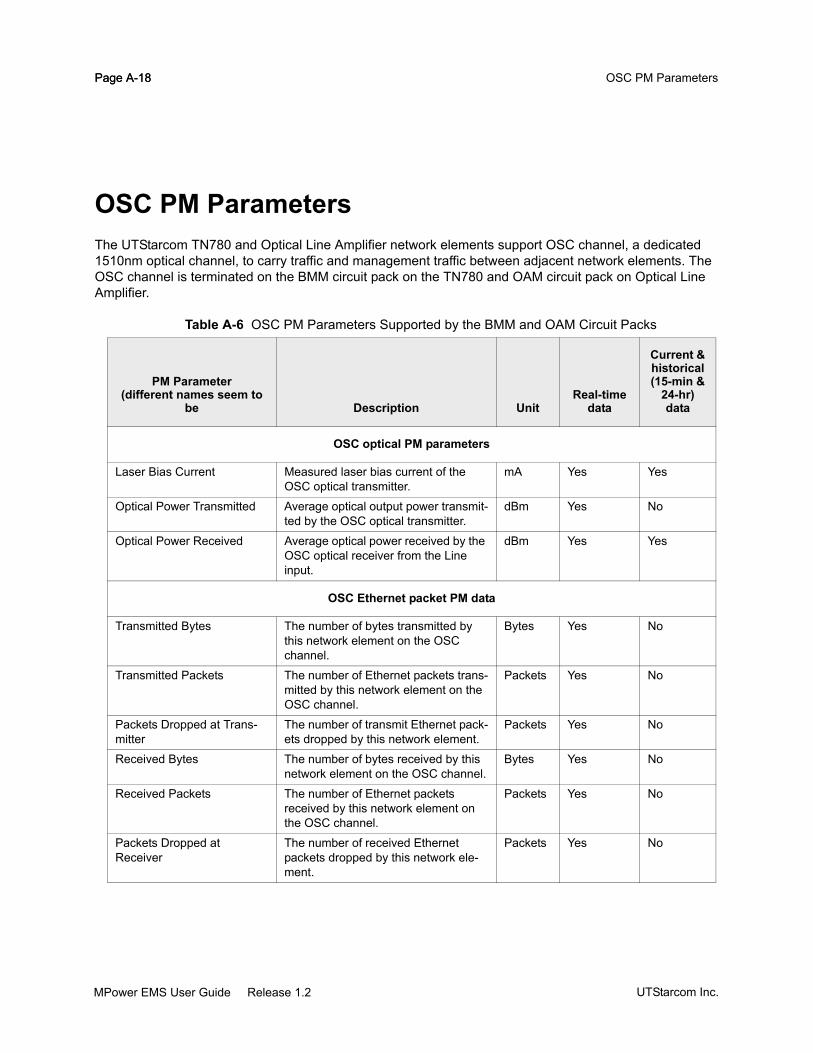
Page A-18 OSC PM ParametersPage A-18
OSC PM ParametersThe UTStarcom TN780 and Optical Line Amplifier network elements support OSC channel, a dedicated 1510nm optical channel, to carry traffic and management traffic between adjacent network elements. The OSC channel is terminated on the BMM circuit pack on the TN780 and OAM circuit pack on Optical Line Amplifier.
Table A-6 OSC PM Parameters Supported by the BMM and OAM Circuit Packs
PM Parameter(different names seem to
be Description UnitReal-time
data
Current & historical(15-min &
24-hr) data
OSC optical PM parameters
Laser Bias Current Measured laser bias current of the OSC optical transmitter.
mA Yes Yes
Optical Power Transmitted Average optical output power transmit-ted by the OSC optical transmitter.
dBm Yes No
Optical Power Received Average optical power received by the OSC optical receiver from the Line input.
dBm Yes Yes
OSC Ethernet packet PM data
Transmitted Bytes The number of bytes transmitted by this network element on the OSC channel.
Bytes Yes No
Transmitted Packets The number of Ethernet packets trans-mitted by this network element on the OSC channel.
Packets Yes No
Packets Dropped at Trans-mitter
The number of transmit Ethernet pack-ets dropped by this network element.
Packets Yes No
Received Bytes The number of bytes received by this network element on the OSC channel.
Bytes Yes No
Received Packets The number of Ethernet packets received by this network element on the OSC channel.
Packets Yes No
Packets Dropped at Receiver
The number of received Ethernet packets dropped by this network ele-ment.
Packets Yes No
UTStarcom Inc.MPower EMS User Guide Release 1.2

Appendix B
MPower Server Alarms
“MPower Server Generated Alarms” on page B-2
MPower EMS User Guide Release 1.2UTStarcom Inc.

Page B-2 MPower Server AlarmsPage B-2
MPower Server Generated AlarmsThe MPower server generates alarms indicating the failure condition so that users can take corrective actions. The alarms generated by the MPower server are displayed in the Alarm Manager window in which the network element generated alarms are displayed. Refer to the Infinera MPower EMS User Guide for procedures to use the Alarm Manager. The MPower server generated alarms include:
The alarms caused by the MPower server to network element connectivity problems. These alarms are categorized as unreachable alarms. See “MPower Server Unreachable Alarms” on page B-2.
The alarms related to the MPower server performance. See “MPower Server Performance Alarms” on page B-11.
MPower Server Unreachable AlarmsAs described in “Configuring Discovery Key Ring” on page 4-16, MPower server establishes connectivity to the network elements. The MPower server reports the alarms listed in Table B-1 on page B-2 when it is unable to establish connectivity to the network element. In the table,
<MPower server account> refers to the login name used by the MPower server to log into the net-work element.
<Network Element ID> refers to the network element the MPower is attempting to connect.
Table B-1 MPower Server Unreachable Alarms<MPower server account> on <Network Element ID> does not have all security privileges on page A-6
<MPower server account> on <Network Element ID> no longer has all security privileges - terminating Server connection to the NE on page A-6
<Network Element ID> is in Errored state. Please contact System Administrator on page A-5
<Network Element ID> unreachable - check connectivity from Server on page A-8
All Server login attempts to <Network Element ID> failed - update key ring with correct user name/pass-words on page A-7
CPU usage of MPower Server High: <% Used> on page A-12
CPU usage of MPower Server: <% Used> on page A-13
Discovery key ring is either empty or corrupt - reconfigure the key ring on page A-11
Disk usage of MPower Server High: <% Used> on page A-14
Disk usage of MPower Server: <% Used> on page A-15
Incompatible Server and NE versions - cannot manage <Network Element ID> on page A-8
Memory Usage of MPower Server High: <-% Used> on page A-17
Memory Usage of MPower Server: <-% Used> on page A-16
Minor Server and NE Version mismatch - some functionality may not be available on page A-9
Redundant path from Server to <Network Element ID> not found on page A-4
UTStarcom Inc.MPower EMS User Guide Release 1.2

Page B-3MPower Server Alarms
Server cannot use <MPower server account> on <Network Element ID> - change password on the NE and then update the key ring on page A-10
Server failed to retrieve XML agent version from <Network Element ID> on page A-8
Server login attempt to <Network Element ID> failed - <Error Message> on page A-10
Server login attempt to <Network Element ID> failed - maximum sessions limit reached on page A-7
Server Lost connection to <Network Element ID> on page A-9
Table B-1 MPower Server Unreachable Alarms
MPower EMS User Guide Release 1.2UTStarcom Inc.

Page B-4 MPower Server AlarmsPage B-4
EMS0001
Redundant path from Server to <Network Element ID> not found Severity - Minor
Description and CausesThis alarm is generated when the MPower server cannot connect to the network element using the secondary DCN path. This alarm is generated only when the MPower server fails to connect to the network element using the primary DCN path.
Clearing Procedure Verify the DCN configuration in the network element and the MPower server
Verify the DCN network configuration
UTStarcom Inc.MPower EMS User Guide Release 1.2

Page B-5MPower Server Alarms
EMS0002
<Network Element ID> is in Errored state. Please contact System Administrator Severity - Unreachable
Description and CausesThis alarm is generated when MPower server cannot discover all managed objects and is not able to login to the network element.
Clearing Procedure Collect all logs in the directory <MPower_home>/EMS/logs where <MPower_home> is the
installed directory of MPower EMS Server.
Contact the System Administrator.
MPower EMS User Guide Release 1.2UTStarcom Inc.

Page B-6 MPower Server AlarmsPage B-6
EMS0009 <MPower server account> on <Network Element ID> does not have all security privileges
<MPower server account> on <Network Element ID> no longer has all security privileges - terminat-ing Server connection to the NE
All Server login attempts to <Network Element ID> failed - update key ring with correct user name/passwords
Server login attempt to <Network Element ID> failed - maximum sessions limit reached
<Network Element ID> unreachable - check connectivity from Server
Server failed to retrieve XML agent version from <Network Element ID>
Incompatible Server and NE versions - cannot manage <Network Element ID>
Minor Server and NE Version mismatch - some functionality may not be available
Server Lost connection to <Network Element ID>
Server cannot use <MPower server account> on <Network Element ID> - change password on the NE and then update the key ring
<MPower server account> on <Network Element ID> does not have all security privileges Severity - Unreachable
Description and CausesThis alarm indicates that the MPower server cannot connect to the specified network element using the specified MPower server account because the account does not have all access privileges.
Clearing ProcedureDo one of the following:
On the network element enable all access privileges for the specified MPower server account.
Delete this account in the MPower server discovery key ring. However, ensure that there is one MPower server account created on the network element and also configured in the MPower server discovery key ring so that MPower server can connect to the network element.
<MPower server account> on <Network Element ID> no longer has all security privileges - terminating Server connection to the NE Severity - Unreachable
UTStarcom Inc.MPower EMS User Guide Release 1.2

Page B-7MPower Server Alarms
Description and CausesThis alarm indicates that the MPower server cannot reconnect to the specified network element using the specified MPower server account because the account does not have all access privileges which was previously enabled. It is most likely caused by a user changing the access privileges of this account.
Clearing Procedure On the network element enable all access privileges for the specified MPower server account
Delete this account in the MPower server discovery key ring. However, ensure that there is one MPower server account created on the network element and also configured in the MPower server discovery key ring so that MPower server can connect to the network element.
All Server login attempts to <Network Element ID> failed - update key ring with correct user name/passwords Severity - Unreachable
Description and CausesThis alarm is generated after MPower server has tried all the MPower server accounts specified in the key ring to connect to the network element, but did not succeed. It is caused by the incompatibility between the MPower server account information configured in the nework element and the information specified in the discovery key ring.
Clearing ProcedureDo one of the following:
Update the key ring with the correct MPower server account name and password which is config-ured in the network element.
Fix the MPower server account name and password in the network element to match the one spec-ified in the key ring.
Server login attempt to <Network Element ID> failed - maximum sessions limit reached Severity - Unreachable
Description and CausesThis alarm is generated when MPower server cannot log into the network element because the maximum active sessions allowed on the network element has exceeded.
MPower EMS User Guide Release 1.2UTStarcom Inc.

Page B-8 MPower Server AlarmsPage B-8
Clearing Procedure Log into the nework element with the security administrator privilege and forcefully terminate one of
the active sessions.
<Network Element ID> unreachable - check connectivity from Server Severity - Unreachable
Description and CausesThis alarm is generated only when the MPower server fails to connect to the network element using the primary DCN path.
Clearing Procedure Verify the DCN configuration in the network element and the MPower server
Verify the DCN network configuration.
Server failed to retrieve XML agent version from <Network Element ID> Severity - Unreachable
Description and CausesThis alarm is generated when the MPower server cannot retrieve the XML agent version running on the network element. This alarm occurs when the network element is not responding to the MPower server.
Clearing Procedure Check the status of the network element and make sure that it is in normal state.
Incompatible Server and NE versions - cannot manage <Network Element ID> Severity - Unreachable
Description and CausesThis alarm is generated when the MPower server version is not compatible with the network element software version. The MPower server cannot be used to manage this network element. For the list of
UTStarcom Inc.MPower EMS User Guide Release 1.2

Page B-9MPower Server Alarms
compatible MPower server and nework element software versions, refer to the “Release Compatibility” on page 1-7.
Clearing ProcedureDo one of the following:
Upgrade the software image on the network element to be compatible with the MPower Server ver-sion.
Upgrade the MPower server version to be compatible with the network element software version.
Minor Server and NE Version mismatch - some functionality may not be available Severity - Minor
Description and CausesThis alarm is generated when the MPower server minor version is not compatible with the network element software minor version. The MPower server can be used to manage the network element, however some functions may not be available.
Clearing Procedure Contact UTStarcom Technical Support for the list of compatible MPower server and network ele-
ment software minor versions. Upgrade the MPower software or the network element software to ensure the compatibility.
Server Lost connection to <Network Element ID> Severity - Unreachable
Description and CausesThis alarm is generated when MPower server loses connection to the specified network element. It could be caused by any of the following reasons:
The network element is reset or unavailable
There is a problem in the connectivity (customer network) between the MPower server and the net-work element.
MPower EMS User Guide Release 1.2UTStarcom Inc.

Page B-10 MPower Server AlarmsPage B-10
Clearing Procedure Ensure that the network element is available. Troubleshoot and fix problems in the network connec-
tivity.
Server cannot use <MPower server account> on <Network Element ID> - change password on the NE and then update the key ring Severity - Unreachable
Description and CausesThis alarm is generated when the MPower server account password has expired on the network element and MPower server cannot log into the network element.
Clearing Procedure Log into the network element and disable the password expiration for this MPower server account.
Server login attempt to <Network Element ID> failed - <Error Message> Severity - Unreachable
Description and CausesThis alarm is generated when MPower server cannot log into the network element. The <Error Message> describes the reason for the failure.
Clearing Procedure Ensure that the MPower server account is properly configured in the network element and the
MPower discovery key ring.
UTStarcom Inc.MPower EMS User Guide Release 1.2

Page B-11MPower Server Alarms
EMS0010
Discovery key ring is either empty or corrupt - reconfigure the key ring Severity - Critical
Description and CausesThis alarm is generated when the discovery key ring is empty or corrupt.
Clearing Procedure Configure the key ring correctly.Refer to “Configuring Discovery Key Ring” on page 4-16 for the
detailed procedure.Refer to the Infinera MPower EMS Administrator Guide for the detailed proce-dure on configuring the discovery key ring.
MPower Server Performance AlarmsMPower server monitors the resource utilization on the workstation on which it is run (referred to as MPower server workstation). When resources are utilized beyond predetermined thresholds, the alarms are reported so that users can take corrective actions.
Table B-2 MPower Server Performance Alarms
Probable CauseFor description and clearing
procedure
“CPU usage of MPower Server: <% Used>“ page B-13
“Disk usage of MPower Server: <% Used>“ page B-15
“CPU usage of MPower Server High: <% Used>“ page B-12
“Disk usage of MPower Server High: <% Used>“ page B-14
“Memory Usage of MPower Server: <-% Used>“ page B-16
“Memory Usage of MPower Server High: <-% Used>“ page B-17
MPower EMS User Guide Release 1.2UTStarcom Inc.

Page B-12 MPower Server AlarmsPage B-12
EMS0003
CPU usage of MPower Server High: <% Used> Severity - Major
Description and CausesThis alarm is generated when the CPU usage on the MPower server workstation exceeds 95%. The <% Used> indicates the current CPU usage.
Clearing ProcedureContact your System Administrator to manage the applications run on the MPower server workstation.
UTStarcom Inc.MPower EMS User Guide Release 1.2

Page B-13MPower Server Alarms
EMS0004
CPU usage of MPower Server: <% Used> Severity - Minor
Description and CausesThis alarm is generated when the CPU usage on the MPower server workstation exceeds 80%. The <% Used> indicates the current CPU usage.
Clearing ProcedureContact your System Administrator to manage the applications run on the MPower server workstation.
MPower EMS User Guide Release 1.2UTStarcom Inc.

Page B-14 MPower Server AlarmsPage B-14
EMS0005
Disk usage of MPower Server High: <% Used> Severity - Major
Description and CausesThis alarm is generated when the disk usage on the MPower server workstation exceeds 95%. The <% Used> indicates the current disk usage.
Clearing ProcedurePerform the following actions:
Back up the MPower server database.
Upgrade the hard disk.
UTStarcom Inc.MPower EMS User Guide Release 1.2

Page B-15MPower Server Alarms
EMS0006
Disk usage of MPower Server: <% Used> Severity - Minor
Description and CausesThis alarm is generated when the disk usage on the MPower server workstation exceeds 80%. The <% Used> indicates the current disk usage.
Clearing ProcedurePerform the following actions:
Back up the MPower server database.
Delete unwanted files, temp directory and logs in the MPower server workstation.
If alarm persists, upgrade the hard disk.
MPower EMS User Guide Release 1.2UTStarcom Inc.

Page B-16 MPower Server AlarmsPage B-16
EMS0007
Memory Usage of MPower Server: <-% Used> Severity - Minor
Description and CausesThis alarm is generated when the memory usage on the MPower server workstation exceeds 80%. The <% Used> indicates the current memory usage.
Clearing ProcedureIncrease the memory size of the MPower server workstation.
UTStarcom Inc.MPower EMS User Guide Release 1.2

Page B-17MPower Server Alarms
EMS0008
Memory Usage of MPower Server High: <-% Used> Severity - Major
Description and CausesThis alarm is generated when the memory usage on the MPower server workstation exceeds 95%. The <% Used> indicates the current memory usage.
Clearing ProcedureIncrease the memory size of the MPower server workstation.
MPower EMS User Guide Release 1.2UTStarcom Inc.

Page B-18 MPower Server AlarmsPage B-18
UTStarcom Inc.MPower EMS User Guide Release 1.2

Appendix C
Acronyms
Acronym Definition
AACLI application command line interface
ACO alarm cutoff
ACT active
AD add/drop
ADM add/drop multiplexer
ADPCM adaptive differential pulse code modulation
AGC automatic gain control
AID access identifier
AINS administrative inservice
AIS alarm indication signal
ALS automatic laser shutdown
AMP amplifier
ANSI American National Standards Institute
AO autonomous output
APD avalanche photo diode
API application programming interface
APS automatic protection switching
ARC alarm reporting control
ARP address resolution protocol
ASAP alarm severity assignment profile
MPower EMS User Guide Release 1.2UTStarcom Inc.

Page C-2 AcronymsPage C-2
ASE amplified spontaneous emission
ASIC application-specific integrated circuit
ATM asynchronous transfer mode
AU administrative unit
AUX auxiliary port
AWG array waveguide gating
AWG american wire gauge
BBDFB battery distribution fuse bay
BDI backward defect indication
BDI backward defect indication
BEI backward error indication
BER bit error rate
BERT bit error rate testing
BGA ball grid array
BIP-8 bit interleaved parity
BITS building-integrated timing supply
BLSR bi-directional line switched ring
BMM-C Band Mux Module - C band
BNC Bayonet Niell-Concelman; British Naval Connector
BOL beginning of life
BOM bill of material
BOOTP bootstrap protocol
bps bits per second
BPV bipolar violations
CC Celsius
CCITT Consultative Committee on International Telegraph and Telephone
CCLI commissioning command line interface
CDE chromatic dispersion equalizer
CDR clock and data recovery
CDRH Center for Devices and Radiological Health
CFR code for federal regulations
CH/Ch/ch channel
Acronym Definition
UTStarcom Inc.MPower EMS User Guide Release 1.2

Page C-3Acronyms
CID circuit identifier
CIT craft interface terminal
CLEI common language equipment identifier
CLI command line interface
CO central office
CODEC coder and decoder
COM communication
CORBA common object request broker architecture
CPC common processor complex
CPE customer premises equipment
CPLD complex programmable logic device
CPU central processing unit
CRC cyclic redundancy check
CSPF constraint-based shortest path first algorithm
CSV comma separated value
CTAG correlation tag
CTP client termination point
CTS clear to send
CV coding violation
CV-L coding violation-line
CV-P coding violation-path
CV-S coding violation-section
DDA digital amplifier
dB decibel
DB database
DCC data communications channel
DCE data communications equipment
DCF dispersion compensation fiber
DCM dispersion compensation module
DCN data communication network
DEMUX de-multiplexing
DFB distributed feedback
DFE decision feedback equalizer
DGE dynamic gain equalization
Acronym Definition
MPower EMS User Guide Release 1.2UTStarcom Inc.

Page C-4 AcronymsPage C-4
DHCP dynamic host configuration protocol
DLM digital line module
DMC dispersion management chassis
DR digital repeater
DSF dispersion shifted fiber
DT digital terminal
DTC digital transport chassis
DTE data terminal equipment
DTF digital transport frame
DTL digital transport line
DTMF dual tone multi frequency
DTP digital transport path
DTS digital transport section
DWDM dense wavelength division multiplexing
EEDFA erbium doped fiber amplifier
EEPROM electrically-erasable programmable read only memory
EMC electromagnetic compatibility
EMI electro-magnetic interference
EMS element management system
EOL end-of-life
ESD electrostatic discharge; electrostatic-sensitive device
ES-L line-errored seconds
ES-P path-errored seconds
ES-S section-errored seconds
ETS IEEE european test symposium
ETSI European Telecommunications Standards Institute
FF fahrenheit
FA frame alignment
FAS frame alignment signal
FC fiber channel; failure count
FCAPS fault management, configuration management, accounting, performance monitor-ing, and security administration
Acronym Definition
UTStarcom Inc.MPower EMS User Guide Release 1.2

Page C-5Acronyms
FCC Federal Communications Commission (USA)
FDA Food and Drug Administration
FDI forward defect indication
FEC forward error correction
FIFO first-in-first-out
FIT failure in time
FLT fault
FPGA field programmable gate array
FRU field replaceable unit
FTP file transfer protocol
GGbE gigabit ethernet
Gbps gigabits per second
GCC general communication channel
GFP general framing protocol
GHz gigahertz
GMPLS generalized multi protocol label switching
GNE gateway network element
GNM graphical node manager
GUI graphical user interface
H/IHTML hypertext markup language
HTTP hypertext transfer protocol
IAP input, output and alarm panel
ID identification
IDF invalid data flag
IEC International Electrical Commission
I/O Input/Output
IOP input output panel
IP Internet protocol
IQ see IQ NOS
IQ NOS UTStarcom IQ network operating system
IR intermediate reach
IS in-service
Acronym Definition
MPower EMS User Guide Release 1.2UTStarcom Inc.

Page C-6 AcronymsPage C-6
ITU-T International Telecommunications Union - Telecommunications
J/K/LJDK Java Development Kit
JRE Java Runtime Environment
LAN local area network
LBC laser bias current
LC fiber optic cable connector type
LCK locked
LED light-emitting diode
Linear ADM linear add/drop multiplexer
LOF loss of frame
LOL loss of light
LOP loss of pointer
LOS loss of signal
LR long reach
LSB least significant bit
LTE line-terminating equipment
LVDS low voltage differential signaling
MMA monitoring access
MAC media access control
MB megabyte
Mb/s megabits per second
MIB management information base
MCM management and control module
MEMS micro electro mechanical systems
MFAS multi frame alignment signal
MIB management information base
MMF multimode fiber
MS multiplex section
MSA multi source agreement
MSB most significant bit
MSOH multiplex section overhead
MTBF mean time between failure
Acronym Definition
UTStarcom Inc.MPower EMS User Guide Release 1.2

Page C-7Acronyms
MTU maximum transmission unit
MX multiplex, multiplexer, multiplexing
NNA network administrator
NAND flash type
NC normally closed; node controller
NCC node controller chassis
NCT nodal control and timing
NDSF non zero dispersion shifted fiber
NE network engineer
NEBS network equipment building system
NECG net electrical coding gain
NEPA national fire protection association
NJO negative justification opportunity
nm nanometer
NML network management layer
NMS network management system
NNI network-to-network interface
NO normally open
NSA non-service affecting
NTP network time protocol
NVRAM nonvolatile random access memory
OOAM optical amplification module
OAM&P operation, administration, maintenance and provisioning
OC-12 optical carrier signal at 622.08 mb/s
OC-192 optical carrier signal at 9.95328 gb/s
OC-3 optical carrier signal at 155.52 mb/s
OC-48 optical carrier signal at 2.48832 gb/s
OCG optical carrier group
Och Optical channel
OCI open connection indication
ODU optical channel data unit
OEO optical-electrical-optical conversion
Acronym Definition
MPower EMS User Guide Release 1.2UTStarcom Inc.

Page C-8 AcronymsPage C-8
OFC open fiber control
OH overhead
OIF optical internetworking forum
OLA optical line amplifier
OMM optical management module
OMS optical multiplex section
OOS out-of-service
OOS-MT out-of-service maintenance
OPR optical power received
OPT optical power transmitted
OPU optical channel payload unit
ORL optical return loss
OS operating system
OSA optical spectrum analyzer
OSC optical supervisory channel
OSNR optical signal-to-noise ratio
OSPF open shortest path first
OSS operations support system
OTC optical transport chassis
OTDR optical time domain reflectometer
OTN optical transport network
OTS optical transport section
OTU optical channel transport unit
OW orderwire
OWM orderwire module
P/QPC personal computer
PCPM per channel power monitoring
PDU protocol data unit; power distribution unit
PEM power entry module
PF partial failure
PG protection group
PHY physical
PIC photonic integrated circuit
PID protocol identifier
Acronym Definition
UTStarcom Inc.MPower EMS User Guide Release 1.2

Page C-9Acronyms
PIN positive-intrinsic negative
PJO positive justification opportunity
PLD programmable logic device
PLL phase locked loop
PM performance monitoring
PMD polarization mode dispersion
POH path overhead
POP point-of-presence
PPM part per million
PPP point-to-point protocol
PR provisioning
PRBS pseudo random binary sequence
ps pico second (unit of measure for dispersion)
PSC protection switch completion; protection switch count
PSD protection switch duration
PSTN public switched telephone network
PT parallel telemetry
PTP physical termination point; point-to-point
PWR power
QOS quality of service
RRAM random access memory
RDI remote defect indication
REI-L remote error indication-line
REI-P remote error indication-path
RFI remote failure indication
ROM read-only memory
RS regenerator section; reed solomon
RSOH regenerator section overhead
RTC real time clock
RTN return lead
RTS ready to send
RU rack unit
Rx receiver; receive
Rx Q receiver quality
Acronym Definition
MPower EMS User Guide Release 1.2UTStarcom Inc.

Page C-10 AcronymsPage C-10
SSA service affecting; security administrator
SAPI source access point identifier
SC square shaped fiber optic cable connector
SD signal degrade
SDH synchronous digital hierarchy
SDRAM synchronized dynamic random access memory
SEF severely errored frame
SEFS severely errored frame second
SELV safety extra low voltage
SERDES serializer and deserializer
SES severely errored seconds
SF signal fail
SFP small form factor plug
SID source identifier; system identifier
SMF single-mode fiber
SML service management layer
SNC sub network connection
SNE subtending network element
SNMP simple network management protocol
SNR signal-to-noise ratio
SOH section overhead
SOL start of life
SONET synchronous optical network
SPE synchronous payload envelope
SQ signal quality
SR short reach
SSL secure sockets layer
STE section terminating equipment
STM synchronous transfer mode
STM-1 SDH signal at 155.52 Mb/s
STM-16 SDH signal at 2.48832 Gb/s
STM-4 SDH signal at 622.08 Mb/s
STM-64 SDH signal at 10 Gb/s
STM-n synchronous transport module of level n (for example, STM-64, STM-16)
Acronym Definition
UTStarcom Inc.MPower EMS User Guide Release 1.2

Page C-11Acronyms
STS synchronous transport signal
STS-n synchronous transport signal of level n (for example, STS-12, STS-48)
SW software
T/U/VTAM tributary adapter module
TAP timing and alarm panel
TCA Threshold Crossing Alert
TCP transmission control protocol
TE traffic engineering
TEC thermo-electric cooler
TERM terminal
TFTP trivial file transfer protocol
TID target identifier
TIM trace identifier mismatch
TL1 transaction language 1
TMN telecommunications management network
TOM tributary optical module
TP termination point
TR transceiver
TT test and turn-up
TTI trail trace identifier
Tx Transmitter; Transmit
UA unavailable seconds
UART universal asynchronous receiver transmitter
UAS unavailable seconds
UAS-L unavailable seconds, near-end line
UAS-P unavailable seconds, near-end STS path
UDP user datagram protocol
UPSR unidirectional path switched ring
URL universal resource locator
UTC Coordinated Universal Time
V volt
VGA variable gain amplifier
VLAN virtual local area network
VOA variable optical attenuator
Acronym Definition
MPower EMS User Guide Release 1.2UTStarcom Inc.

Page C-12 AcronymsPage C-12
VPN virtual private network
VSR very short reach
W/X/Y/ZWAN wide area network
WDM wavelength division multiplexing
XC cross-connect
XFP name of a small form factor 10 Gbps optical transceiver
XML extensible markup language
MISC1R re-amplification
2R re-amplification, re-shape
3R re-amplification, re-shape, re-time
4R re-amplification, re-shape, re-time, re-code
Acronym Definition
UTStarcom Inc.MPower EMS User Guide Release 1.2