uu.diva-portal.orguu.diva-portal.org/smash/get/diva2:167309/fulltext01.pdflist of papers i...
TRANSCRIPT

Dedicated to my wife Karolina
“When faced without a challenge, make one” Peter’s Law no. 12 by Peter Diamandis

List of papers
I Nanospace-1: the Impacts of the first Swedish Nanosatellite on Spacecraft Architecture and Design, F. Bruhn, J. Köhler, L. Sten-mark, Acta Astronautica, vol. 53, pp. 633-643, 2003. (Invited paper)
II NanoSpace-1: Spacecraft Design using Advanced Modular Archi-tecture, F. C. Bruhn, P. Rathsman, L. Stenmark, submitted to AIAA Journal of Spacecraft and Rockets, 2005.
III Spacecraft Design Optimization – A Multifunctional Microsystem Module Implementation Method, F. C. Bruhn, J. Köhler, L. Sten-mark, G. Thornell, submitted to AIAA Journal of Spacecraft and Rockets, 2005.
IV Distributed Communication Architecture in Spacecraft System-of-Microsystems – A Preliminary Analysis, F. C. Bruhn, Sven-Erik Jansson, P. Nilsson-Zandkarimi,, J. Köhler, O. Redell, Submitted to Journal of MEMS, 2005.
V MEMS Enablement of Miniature Autonomous Submersible Ex-plorer, F. C Bruhn, F. D. Carsey, J. Köhler, M. Mowlem, C. Ger-man, L. Stenmark, and A. E. Behar, IEEE Journal of Oceanic En-gineering, vol. 30, pp. 165-178, Jan 2005.
VI A preliminary Design for a Spherical Inflatable Microrover for Planetary Exploration, F. C. Bruhn, J. Warell, C-I. Lagerkvist, V. Kaznov, J. A. Jones, L. Stenmark, Accepted in Acta Astronautica 2005.
VII Extremely Low Mass Spherical Rovers for Extreme Environments and Planetary Exploration Enabled with MEMS, F. C. Bruhn, K. Pauly, V. Kaznov, 8th Int. Symp. on Artificial Intelligence, Robot-ics and Automation in Space, 16-20 September, Munchen, Ger-many, 2005. (Invited paper)
The contribution by the author to the papers included in the thesis is as fol-lows:
I Significant part of the planning. Major part of evaluation and writ-ing.
II Major part of the planning and evaluation. All of the writing.
III Major part of the planning and evaluation. All of the writing.
IV Major part of the planning and evaluation. Substantial part of the writing.
V Major part of the planning and evaluation. Substantial part of the writing.
VI Substantial part of the planning, evaluation, and writing.
VII Substantial part of the planning. Major part of evaluation. Signifi-cant part of the writing.
Papers are reproduced with permission from the publishers.

Contents
Introduction.....................................................................................................9
System design with respect to microsystems................................................11Benefits of MMS......................................................................................11Related work ............................................................................................14Limits .......................................................................................................16
Space environment...............................................................................17The mass penalty......................................................................................18Reduce mass to cut cost ...........................................................................18Modularity for cutting cost and gaining performance..............................19
Enabling powerful and low weight spacecraft and robotic vehicles.............20General aspects on MMS modules and spacecraft design........................20NanoSpace-1 - the MST technology demonstration frontier ...................22A scalable, modular and high performance spacecraft bus ......................24Advanced robotic applications enabled with MMS .................................24
Miniature Autonomous Submersible Explorer ....................................24Spherical Mobile Investigator of Planetary Surfaces (SMIPS) ...........26
What about spacecraft on chip and Pico Satellite Design? ...........................28
Summary of papers .......................................................................................29Summary of Paper I: Nanospace-1: the Impacts of the first Swedish Nanosatellite on Spacecraft Architecture and Design (invited) ...............29Summary of Paper II: NanoSpace-1: Spacecraft Design using Advanced Modular Architecture ...............................................................................29Summary of Paper III: Spacecraft Design Optimization – A Multifunctional Microsystems Module Implementation Method ............30Summary of Paper IV: Distributed Communication Architecture in Spacecraft System-of-Microsystems – A Preliminary Analysis ..............30Summary of Paper VI: MEMS Enablement of Miniature Autonomous Submersible Explorer ...............................................................................30Summary of Paper VII: A preliminary Design for a Spherical Inflatable Microrover for Planetary Exploration ......................................................31

Summary of Paper VII: Extremely Low Mass Spherical Rovers for Extreme Environments and Planetary Exploration Enabled with MEMS (invited) ....................................................................................................31
Appendices....................................................................................................32TRL definition..........................................................................................32Spacecraft naming definition....................................................................32
Acknowledgements.......................................................................................34
Sammanfattning på svenska: Miniatyriserad multifunktionell systemarkitektur för satelliter och robotik ....................................................36
References.....................................................................................................38

9
Introduction
Microengineering is one of the newest tools available to the space commu-nity. Several technology leaps have been taken in space design over the years and microengineering may represent the largest step ever. Microengi-neering, or microstructure technology (MST), or microelectromechanical systems (MEMS) initiates an even larger revolution than the introduction of surface mounted devices (SMD). MST represents a potentially better ap-proach since it provides the possibilities for multifunctional designing, i.e. MST is not a specific tool like SMD, but rather a broad method to add elec-tronics, mechanical functions (e.g. structure load carrying, valves, micro-pumps, filters) and thermal handling.
As with any new technology in the space business, flight qualification and flight heritage is important. These two areas are difficult to fulfill because of the conservative thinking of space managers around the world. One major goal of this thesis is to present technologies and ideas that can help bridge the MST “valley of death”, i.e. the phase where devices and systems matures from breadboard to flight systems [1].
MST has been successfully applied to numerous applications on Earth and in space [2-5]. However, these systems are often on device level and require a hybrid, or fully traditional setup around the device to work.
Dr. Siegfried Janson et al. of the Aerospace Corporation, USA went a long way in 1993 when they laid out the goals of spacecraft built from sili-con using MST techniques [6]. Janson’s et al. vision has not yet come true, but the work of Dr. Johan Köhler in his PhD thesis, “Bringing micro-systems to space” sets the scene for highly MST dependable spacecraft. Köhler’s thesis addresses the implementation of MST, and in particular multifunc-tional microsystems (MMS) in spacecraft design [7].
My thesis will discuss in detail the implementation of MMS in spacecraft and space robotic design, evaluation of new space mission opportunities, and general system aspects. Detailed design of a next generation high performing nanosatellite is discussed in Papers I, II, and III. Paper I is included to sum-marize the work that was done before I started my research and to identify the interesting areas of research. Further information regarding spacecraft classification and technology readiness levels is given in the appendices. Additional work on enabling technologies and applications is discussed in Papers IV and V.
10
In the pursuit of demonstrating the wide applicability of the toolbox de-noted MMS, designs of a robotic vehicle for Jupiter’s icy moon Europa and networked exploration of our Moon and Mars have been investigated and evaluated in Papers VI, VII, and VIII.
The main track of this thesis is on the definition, design, evaluation, and construction of NanoSpace-1 (NS1) recently renamed Micro-Link 1 (ML-1). This is a technology satellite test-bed for disruptive technologies, and in particular multifunctional microsystems. NS-1 is a 10 kg spacecraft, hence classed as a nanosatellite by definition (appendix 2). It is designed with the aim to be a relatively low-cost platform enabling recurring spaceflight op-portunities for space qualification and evaluation of MMS modules and MST devices. The major research and development driver has been an internally enforced goal of designing a 10 kg spacecraft with the relative performance of order-of-magnitude larger satellites. This thesis shows that it is possible to meet the system and performance envelopes of larger spacecraft with effec-tive nanosatellites forged on the development and advances of multifunc-tional microsystems.
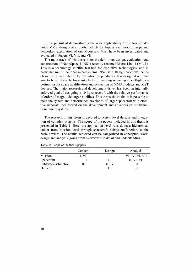
The research in this thesis is devoted to system level designs and integra-tion of complex systems. The scope of the papers included in this thesis is presented in Table 1. Here, the application level runs down a hierarchical ladder from Mission level through spacecraft, subsystem/function, to the basic devices. The results achieved can be categorized in conceptual work, design and analysis, going from overview into detail and understanding.
Table 1: Scope of the thesis papers
Concept Design Analysis Mission I, VII I VII, V, VI, VII Spacecraft I, III III II, VI, VII Subsystems/function III III, V III Device III III
11
System design with respect to microsystems
This thesis is devoted to developing, defining, evaluate, and applying Multi-functional MicroSystems (MMS) in various applications. Since no MMS system has yet evolved above Technology Readiness Level (see appendix 1) 4 to 5, it is difficult to estimate the quality of the technique, although an as-sessment is done in Paper II and Paper IV. Quality in this context means long time stability and degradation, impacts of unforeseen problems, etc…
Benefits of MMS A multifunctional design differs from traditional subsystem-oriented de-
sign in that there are no subsystems per se, but rather implementations of functions. In a functionally-designed spacecraft or system, the design proc-ess emphasizes the identification and specification of functional require-ments using the usual front-end systems engineering procedures. However, the identified requirements are never specifically allocated to a physical sub-system. Instead, the various required spacecraft functions are implemented in suitable building blocks without regard to traditional spacecraft subsystem boundaries. This means that single components or multiple subsystems can be implemented in the same building block.
In the MMS concept, functional modules are used to implement higher-level mission-specific functions or to fulfill mission requirements. In particu-lar, introduction of MMS will enable redistribution of functionality from single expensive platforms to high-performing nano/microsatellites. The MMS concept is developed to be a generic design concept that is easily adaptable to different missions and requirements. Subsystem functions are distributed across multiple MMS modules. Each MMS can also be a struc-tural element (“building block”) that contains embedded electronics, conduc-tors, and thermal control. Traditional subsystem boundaries (and their asso-ciated penalties) no longer exist.
Three important definitions are defined for the overall functionality of a MMS based system [Paper I, II, and III]:
Adding functional modules as required Swapping/adding MMS Replacing selected functions/modules on a satellite design
12
The second definition to allow swapping of MMS modules are the most difficult to fulfill since the wiring in a spacecraft is usually different for each module. The implementation of MMS offers extreme miniaturization and weight savings from the reduction or even elimination of black boxes, wire harnesses, dead volumes, heavy radiation shielding, and connectors.
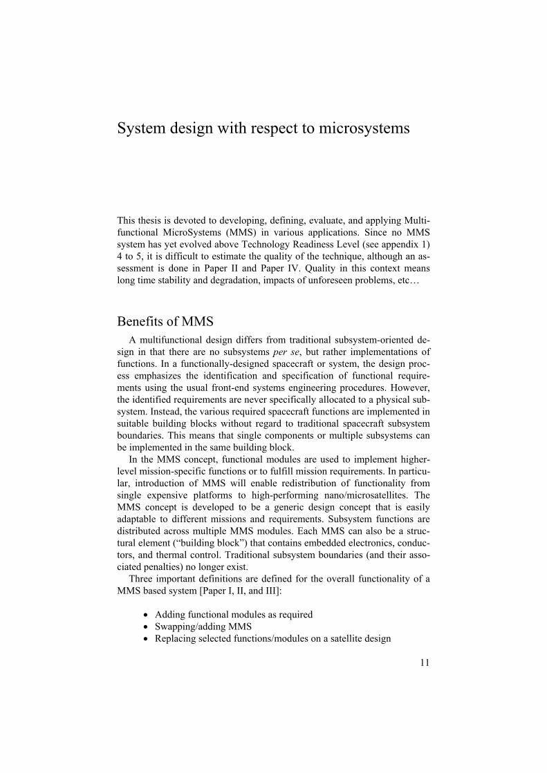
Figure 1 illustrates the MMS concept strategies and techniques for minia-turization and optimization. The toolbox available for MMS is divided into six major areas, which are equally important.
Functional modularization is the trade of traditional subsystems versus distribution of functions over one or several modules.
High-level integration is the level of integration in each module of MMS “block”.
Packaging, functional modularization, high and low level integration, mi-crotechnology and structure are necessary parts of a successful general mod-ule building block. An ultimate solution should always be to design a mod-ule that makes use of all six areas.
This can be illustrated in the following way: assume that one would like to miniaturize a printed circuit board that has a common communication interface, a protective casing, a connector, and some electronics. Applying Fig. 1 the miniaturized system should provide a casing, accommodate a con-nector, contribute to the structure, have the original functionality, and inte-grate the electronics.
Figure 1. Illustration of the MMS concept strategies and techniques. The conse-quence of creating spacecraft building blocks that approaches all six areas is high performance. This is enabled when every single building block is given properties from not only mechanical or electrical aspects, but rather from new packaging material, miniaturization of electronics, integration of advanced thermal properties, being part of the senabl tructure, ing high-level integration in the package, etc.
13
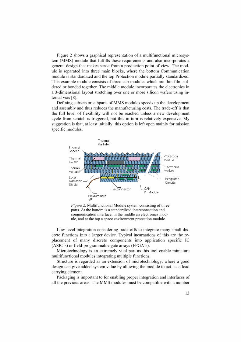
Figure 2 shows a graphical representation of a multifunctional microsys-tem (MMS) module that fulfills these requirements and also incorporates a general design that makes sense from a production point of view. The mod-ule is separated into three main blocks, where the bottom Communication module is standardized and the top Protection module partially standardized. This example module consists of three sub-modules which are thin-film sol-dered or bonded together. The middle module incorporates the electronics in a 3-dimensional layout stretching over one or more silicon wafers using in-ternal vias [8].
Defining subsets or subparts of MMS modules speeds up the development and assembly and thus reduces the manufacturing costs. The trade-off is that the full level of flexibility will not be reached unless a new development cycle from scratch is triggered, but this in turn is relatively expensive. My suggestion is that, at least initially, this option is left open mainly for mission specific modules.
Low level integration considering trade-offs to integrate many small dis-crete functions into a larger device. Typical incarnations of this are the re-placement of many discrete components into application specific IC (ASIC’s) or field-programmable gate arrays (FPGA’s).
Microtechnology is an extremely vital part as this tool enable miniature multifunctional modules integrating multiple functions.
Structure is regarded as an extension of microtechnology, where a good design can give added system value by allowing the module to act as a load carrying element.
Packaging is important to for enabling proper integration and interfaces of all the previous areas. The MMS modules must be compatible with a number
Figure 2. Multifunctional Module system consisting of three parts. At the bottom is a standardized interconnection and communication interface, in the middle an electronics mod-ule, and at the top a space environment protection module.
14
of packaging methods where the most common one is using silicon wafers as the bulk material.
A balanced concept that makes sense and touches on each strategy in fig-ure 4 has obvious benefits, and can be defined as a multifunctional micro-system (MMS).
Thus, a fully optimized MMS would make use of the best low-level inte-grated monolithic devices, package them in the best high-level package to-gether with mechanical functions using microtechnology, and finally be part of the satellite structure.
However, while each of these techniques and strategies has its own ad-vantages, none by itself is truly enabling for implementing the next genera-tion of high-performing nanosatellites. Particularly important, as for any modularized system is the trade-off between performance, scalability, and technology lifetime. The MMS modules are manufactured as complex bonded silicon structures and cannot, by its nature be easily changed. There-fore, MMS require process maturity and exceptionally skilled planning to meet the technology lifetime requirement.
Related work The Multifunctional Structure (MFS) approach by Lockheed-Martin and others clearly illustrates a tremendous progress in this field, although not yet coming to a design strategy that incorporates all techniques [9-10]. MFS is a very similar technology to the MMS that aims to reduce or completely re-move the cables and connectors. The walls of the spacecraft are covered with a flexible film which holds the conductors for MCMs and other components. MFS touches on many of the strategies presented in Fig. 1, although it doesn’t not go to the extreme high-level integration that MMS does. Many circuits in the MFS concept are socketed, or mounted in groups onto a car-rier, which would then be placed on a corresponding socket, in order to be replaceable. In this way are parasitic masses and volumes removed.
A similar approach with larger “sockets” is taken with the MMS concept, by incorporating a flexible film that contains all conductors, on the backside of larger MMS module arrays. On NanoSpace-1, printed circuit boards are used as intermediate shell. On these PCBs are all conductors are located. The MFS concept has been verified on the NASA Deep Space-1 mission. The MFS uses a structural panel as mounting device; the panel also incorporates integral thermal control. The panels can incorporate capillaries and a capil-lary pump loop to liquid cool areas with high power densities. The MMS technology is really a mixture of all techniques mentioned above.
Calculations made by the US. Air Force Research Laboratory (AFRL) on the STRV study using MFS shows a typical reduction of 70-90% in mass and volume and more than 30% in power [11]. Calculations performed by

15
the author using MMS technology on a submersible vehicle for the Jovian Moon Europa shows an increase in packing density of 25 times [12].
A truly functional design methodology represents a complete paradigm shift in spacecraft design. MMS capitalize on the volumetric benefits of en-capsulating traditional and necessary components (e.g. propellant tanks, batteries, etc...) in a functional shell.
Using the possibility to use the structure for implementation of high-level systems, such as power regulation, battery recharging, distribution and ther-mal control is very important in order to get a balanced concept. MMS fur-ther allows for commercial-off-the-shelf (COTS) to be implemented, al-though it requires naked dies to be used for high-level integration, but on the other hand semi-conductor manufacturers are making their components read-ily available as naked dies in addition to the traditional packaging. Surrey Satellites Technology Limited have successfully demonstrated the use of COTS in space and also demonstrated some initial degree of modularization [13]. However, Surrey’s approach has been more oriented on sales than technology enhancements and they still rely heavily on traditional Printed Circuit Boards (instead of microsystem integration).
A major difference between the proposed MFS concept or a higher order system approach based on MFS the Reconfigurable Multifunctional Archi-tecture (RMA) concept compared to MMS as it is implemented in the ÅSTC distributed system-of-microsystems is that the common bus is routed differ-ently [14]. In the systems-of-microsystems there are one thin flexible panel on each side of the spacecraft and also across that interconnects all modules to the power bus and the Controller Area Network (CAN) bus (Paper IV).
In the MFS concept the common bus is typically positioned on the same multifunctional structure as the satellite functions and interconnections are made using small flexible hinges at each corner, where two building blocks intercepts. The MMS concept is more flexible since it has “free” and inde-pendent modules, whereas the MFS require a larger panel, to be mounted and connected.
There is a slightly larger overhead with the MMS interconnection scheme in terms of more and smaller modules, but this can effectively be minimized if the flexible film is positioned in an intermediate shell, working between the outer shell and the core elements, as demonstrated on the NanoSpace-1 spacecraft (Paper II).
Don Hunter from the Jet Propulsion Laboratory has pursued a concept called Integrated Avionics System (IAS) which in nature is quite close to MMS [15]. IAS is a design philosophy that provides a low-mass, modular distributed or centralized packaging architecture which combines ridged-flex technologies, high-density COTS hardware and a 3-dimensional mechanical packaging approach. IAS shares some of the thoughts from the MFS concept described above. Although IAS focuses on reduction of mechanical inter-faces, an electronics comparison with MMS can be made. IAS is designed to
16
work as load-carrying elements of a spacecraft. This is done effectively through interconnection between the flex plates that forms the base of IAS. Since IAS is formed around several flex panels it is also possible to form a box shape. The typical size of a MMS module for the NanoSpace-1 space-craft is 68x68x3mm where in the IAS case the typical dimensions are simi-lar, 50x50x12.7mm.
A major difference is that the IAS is mounted inside an aluminum frame while the MMS is constructed around silicon wafers. This has a significant impact in implementation possibilities since the MMS is a solid structure that can be formed using micromachining for various functions, while in the IAS case, much space is non-occupied. This results from the fact that IAS using flex boards with surface-mounted components in a layered configura-tion inside the IAS frames. 3-dimensional packaging is creating by intercon-necting the flex boards internally. MMS systems can reduce even further by packaging everything closer together using micro machining. The silicon wafers used in MMS are also better heat conductors that flex boards and are therefore more suitable to handle higher heat fluxes. If needed, local micro-machined heat pipes or micropumps can be incorporated in the MMS con-cept.
Limitations The single most important issue to MMS design is manufacturing limits
and process yields. Köhler et al. have performed preliminary analysis of the process yields for manufacturing of multifunctional microsystems modules [7].
There are several differences compared to traditional yield modeling and yield management approaches, as described by Roos, Atchison, and Manson [16, 17]. MMS design for space applications will have limited series which in turn will give a low number of samples to verify for yield. MMS also involves a complex internal structure with many various process steps and process types.
A comparison can be made to modern semiconductor manufacturing with large volumes such as CPUs or FLASH memories. First, the semiconductor manufactures uses similar process types and process steps throughout the entire line and does not involve many different functions. This fact together with automated process lines allow for traditional yield management to be applied and intensively analyzed as the ramp up in production creates mas-sive amounts of wafers. Second, the semiconductor manufacturers have well developed simulation tools that help minimize systematic yield problems. Third, reduced yield losses can be through development and quality assur-ance of equipment and processes. Fourth, two major drivers are important when building a CPU or a FLASH memory, namely the clock frequency and

17
the number of transistors. The number of transistors in turn determines the power consumption and thus, the maximum clock frequency and the manu-facturing complexity.
Analyzing yield effects in MMS is quite different since the series are small and there are no complete software to simulate the complex processes and mixtures of functions. The existing software also has problems to simu-late the three-dimensional structure that is inherited in the MMS design. Since space is a constrained market there are not massive amount of devel-opment funds which together with many different process types lead to a substantial systematic yield problem on top of random yield effects. Reduc-ing the systematic yield errors are extremely important for MMS and re-quires massive quality assurance implementations [7]. In our comparison with the semiconductor industry were few parameters dominate the perform-ance, an MMS have many parameters and functions which substantially raise the yield complexity. Specifically a MMS module does require bonding of several and most often structured silicon wafers. The bond interfaces are extremely critical and necessary in order to verify the functionality in the MMS since many functions are distributed over several wafers.
Space environment The space environment will put requirements on the MMS modules in
terms of radiation hardening and micrometeorite impacts [18]. The impor-tance of this is strongly related to commercial aspects. The largest markets for spacecraft are in Low-Earth Orbits (LEO) and in Geo-Equatorial Orbits (GEO). However, these orbits have very different characteristics. GEO orbits are close to the upper Van Allen belt and therefore generate much higher radiation doses that the system must tolerate.
In response to this, the MMS development can be divided into three cate-gories which corresponds to market opportunities and requirements by the science community. These three segments are defined according to this:
1. Low Earth orbit (low radiation from Van Allen belts) 2. Interplanetary travel and small interplanetary bodies 3. High doses from radiation belts
The modules should be designed according to Fig. 2, i.e. in a way so that radiation shielding can effectively be added without introducing a com-pletely new design of the whole module. This can be done by allowing for extra silicon wafers with shielding material to be added on-top of the mod-ules. An example on this is the s-band antenna design by Kratz et al. [19]. In this design paraffin heat storage is added. This can be modified for various thicknesses in order to increase radiation protection. In this context it can be noted that the first set of modules that will fly on NS-1 will be designed for

18
Low Earth Orbit (segment 1) and moderate radiation doses. Changing a module design for segment 1 and adapting it for segment 2 and 3 typically involves adding radiation shielding: however, in some cases where highly energetic particles have a high probability of causing single event latch-ups (short circuits) one may also have to take precautions by adding radiation hardened electronics.
The mass penalty Space travel and space exploration are difficult and require large rockets. Around this fundament is all government sponsored launchers forged. A few are challenging this fundament, especially in the United States. Companies like Space-X are anticipating smaller and more capable spacecraft. Also the European Space Agency (ESA) is working on smaller launchers, namely the Vega launcher.
Going into space is typically a 1:100 weight ratio, i.e. for every kg in orbit it requires 100 kg propellant and support structures on the surface of Earth. The American space shuttle has a lift of mass of about 2000 metric tons, or 2 million kg. The obvious way to reduce cost taken the mass penalty ratio into account is to lower the launch mass. However, many systems have a mini-mum size defined by connectors and traditional setups.
Reduce mass to cut cost The idea of reducing mass to cut cost is really tempting since it should be feasible to have smaller launchers. Smaller spacecraft should also be quicker to assemble and can possible allow for clusters to be deployed in a single launch [20, 21]. However, reducing the spacecraft mass typically means cutting scientific value of the spacecraft due to decreased payload capability. This can be exemplified with the Surrey Satellite Technology Ltd (SSTL) SNAP-1 bus [22] and Munin developed by the Swedish Institute of Space Physics (IRF) in Kiruna [23, 24]. Both have been successfully launched and operated in space.
A short comparison between SNAP-1 and the Ångström Space Technol-ogy Centre’s NanoSpace-1, Paper II, shows large differences, mainly due to electronics development over several years, and microsystems implementa-tions. For instance, the total delta-V of the spacecraft can be increased from 3.5 to about 100 m/s. The power capability in nominal mode increases from 5-6 W to 64 W. The battery capacity increases from 10 Whr to 172 Whr. Furthermore, many systems on the NanoSpace-1 satellite are redundant. It is quite clear that the scaling down of traditional spacecraft reduces perform-
19
ance and scientific value while implementing MST on all levels can keep relative performances and provide extraordinary spacecraft.
Deploying highly integrated and MST-enabled spacecraft will increase the development costs, and make the paradigm void the belief that smaller spacecraft is significantly cheaper. The savings in launch costs are still valid but the development costs of these technologies drive the cost. No complete spacecraft has been built using MMS derived architecture yet and therefore the costs are only estimations. The best cost estimate today for development on the NanoSpace-1 spacecraft puts it at about 100 million Swedish Kronor (SEK) ~ 10 million Euro.
Modularity for cutting cost and gaining performance Many systems on Earth utilize modularity and distributed intelligence to lower cost and increase performance, e.g. most cars today use a serial com-munication link with smart “nodes”. For instance, the signal lights of a car is turned on by sending a serial command to each light, which in turn will blink until further notice that they should stop. In each of the lights a smart node is employed that allowing the light a certain degree of freedom and distributed intelligence.
The introduction of modularity and systems distribution has long been de-sired in spacecraft design. The conventional and conservative space design rules together with the requirement to keep mass as low as possible have effectively restricted these approaches. This is mainly because the conserva-tive ways of designing spacecraft tend to require that each node or subsys-tem should be packaged in a protective cover and be equipped with bulky connectors.
Distribution of intelligence and distributed sensors are widely imple-mented into space robotics [25, 26]. This is mainly due to complex wiring, which can be significantly reduced using serial data communication and smart nodes. The Scorpion and ARAMIES robots developed by ESA and the University of Bremen are excellent demonstrators where distributed intelli-gence has been applied [27, 28]. A backside of this approach is that each node gets fairly large when using traditional technologies. Introducing MST and vertically integrated multi-chip-modules can significantly reduce the sizes of interconnects and electronics and subsequently significantly de-crease the mass involved. The SCORPION robot has 24 distributed me-chanical nodes or joints, were each joint comprises connectors, a dc-motor, motor driving electronics, a processor, and communication transceivers. Reducing each node by 50-70% is within reach using MMS which would make a large difference on this multi-node system. Furthermore, the mass would scale even better since the supporting robotic body and mechanics can then be made lighter.

20
Enabling powerful and low weight spacecraft and robotic vehicles
General aspects on MMS modules and spacecraft design
For any successful implementation of MMS to make a profound step for-ward in spacecraft design, at least the following properties must be accom-modated (Paper III):
Enabling low weight high performance support systems Enabling low weight high performance scientific payloads Enable a scalable and modular design Enable autonomy and distributed intelligence
Scalable design is highly wanted due to several reasons. First scalable de-signs will enable a larger market for the products. If a specific multifunc-tional Microsystems module can work over a range of spacecraft sizes, from nanosatellites to large spacecraft, the number of potential customers’ in-creases. Creating a scalable design however requires careful planning. Three major issues have to be considered (Paper I), the lifetime, the performance, and the technology lifetime of a MMS module, i.e. the time before the mod-ule must be updated due to new technology or higher demands in processing capabilities. The performance of the module is deeply connected to the scal-ability and the classification of the module. Classification means mission specific or general type in modules. General types of modules are better economically but may not make sense for specific application. It is antici-pated that at least one module is mission specific for MMS enabled space-craft.
Modularity is also important when looking at the business case for MMS modules. The reason why is that the complexity involved in the manufactur-ing of MMS modules does not allow all conventional subsystems to be miniaturized. Many systems would also require a process complexity that simply cannot be accomplished today. Therefore, by adding a modulariza-tion requirement we can ensure that larger systems can accommodate and minimize the overhead introduced with each module. This is closely related

21
to scalability of the system and states that any module should be fully func-tional in itself and not depend on any other (except for power and data com-munication).
This can be exemplified with power generation and conditioning mod-ules. One or more power generating modules may be used on the same spacecraft. The modularity requirement states that they must be able to work on their own without being aware of the others. This again relates to the fact that it may be impossible to build a power generation module that can sus-tain a large spacecraft directly, and, thus the complete power generation function would have to be built up from smaller units. At the same time it is desired that the systems make use of the benefits of having more than one power generation modules on-board. Paper I and II define an algorithm in-cluded in each power module for balancing load. Thereby the characteristics of modularity, and scalability is preserved.
Autonomy and distributed intelligence are also closely related to both scalability and modularity. For any system to be modular it must comprise a communication system. These systems are widely used on Earth, the largest one being the Search for Extra Terrestrial Intelligence (SETI) software that runs of thousands of computers world wide. The problem is that distributed systems require large bandwidth which is undesired due to power constraints on spacecraft. In order to reduce the need of bandwidth, two methods are employed: introduction of group addressing in the on-board communication protocols (to reduce the number of packets that need to be transmitted) and implementation of autonomy in several nodes [Paper IV]. Allowing nodes to have autonomy reduces both the software complexity of the central on-board computer and the bandwidth requirements. Paper II, IV, and V discuss dis-tribution and autonomy of spacecraft functions.
The economical gains of creating low weight spacecraft are two-fold. The cost of launching a spacecraft is significantly reduced and with the current large launchers, the small size and low mass of nano-satellites makes it fea-sible to launch many satellites together, further reducing the launch cost per satellite. This opens up possibilities for new mission scenarios where clusters or constellations of “nano” spacecraft can synthesize functions previously requiring much larger spacecraft. However, since individual nanosatellites may have performance capabilities comparable to those of micro- and small satellites, it is possible to create “super clusters” or “super constellations” within flight mass constraints. The importance of satellite constellations for both Earth and Space Science has been summarized in a number of papers in the past [20, 21].
22
NanoSpace-1 - the MST technology demonstration frontier
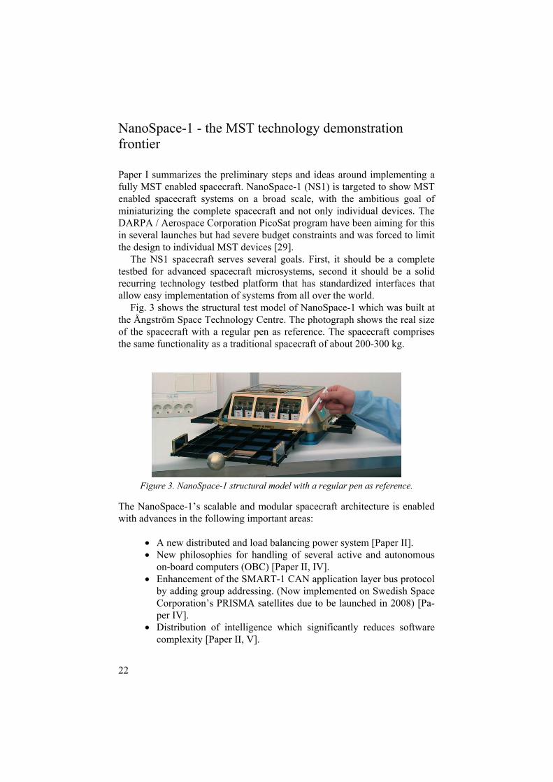
Paper I summarizes the preliminary steps and ideas around implementing a fully MST enabled spacecraft. NanoSpace-1 (NS1) is targeted to show MST enabled spacecraft systems on a broad scale, with the ambitious goal of miniaturizing the complete spacecraft and not only individual devices. The DARPA / Aerospace Corporation PicoSat program have been aiming for this in several launches but had severe budget constraints and was forced to limit the design to individual MST devices [29].
The NS1 spacecraft serves several goals. First, it should be a complete testbed for advanced spacecraft microsystems, second it should be a solid recurring technology testbed platform that has standardized interfaces that allow easy implementation of systems from all over the world.
Fig. 3 shows the structural test model of NanoSpace-1 which was built at the Ångström Space Technology Centre. The photograph shows the real size of the spacecraft with a regular pen as reference. The spacecraft comprises the same functionality as a traditional spacecraft of about 200-300 kg.
Figure 3. NanoSpace-1 structural model with a regular pen as reference.
The NanoSpace-1’s scalable and modular spacecraft architecture is enabled with advances in the following important areas:
A new distributed and load balancing power system [Paper II]. New philosophies for handling of several active and autonomous on-board computers (OBC) [Paper II, IV]. Enhancement of the SMART-1 CAN application layer bus protocol by adding group addressing. (Now implemented on Swedish Space Corporation’s PRISMA satellites due to be launched in 2008) [Pa-per IV]. Distribution of intelligence which significantly reduces software complexity [Paper II, V].
23
Miniaturization of standardized Controller Area Network (CAN) & ESA SpaceWire (SpW) user interfaces [Paper IV]. New MST interconnection methods. Division from traditional subsystems into multifunctional entities called modules, i.e. physically limited modules which can house one or several functions [Paper II, III]. General miniaturization of all systems using MST [Paper II].
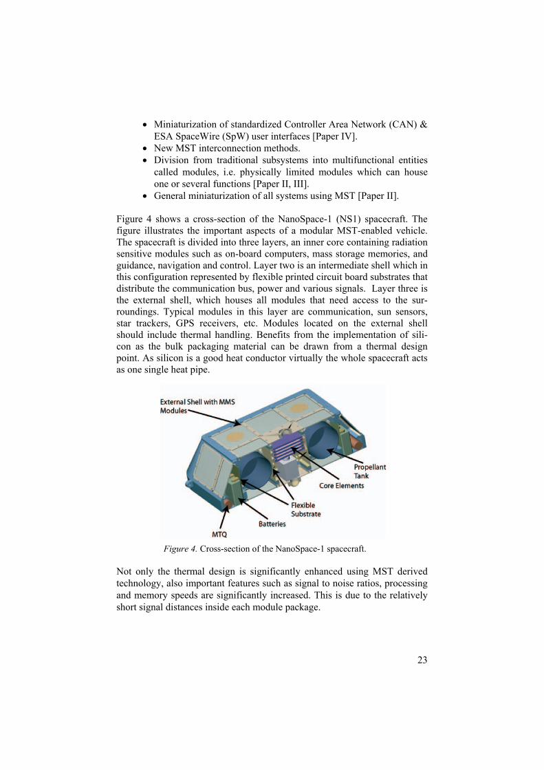
Figure 4 shows a cross-section of the NanoSpace-1 (NS1) spacecraft. The figure illustrates the important aspects of a modular MST-enabled vehicle. The spacecraft is divided into three layers, an inner core containing radiation sensitive modules such as on-board computers, mass storage memories, and guidance, navigation and control. Layer two is an intermediate shell which in this configuration represented by flexible printed circuit board substrates that distribute the communication bus, power and various signals. Layer three is the external shell, which houses all modules that need access to the sur-roundings. Typical modules in this layer are communication, sun sensors, star trackers, GPS receivers, etc. Modules located on the external shell should include thermal handling. Benefits from the implementation of sili-con as the bulk packaging material can be drawn from a thermal design point. As silicon is a good heat conductor virtually the whole spacecraft acts as one single heat pipe.
Not only the thermal design is significantly enhanced using MST derived technology, also important features such as signal to noise ratios, processing and memory speeds are significantly increased. This is due to the relatively short signal distances inside each module package.
Figure 4. Cross-section of the NanoSpace-1 spacecraft.
24
A scalable, modular and high performancespacecraft bus
During the development of NanoSpace-1, 13 main modules have been identified and motivated (Paper II). The modules are derived being applica-ble over a range of satellite configurations, including today’s larger space-craft. The breakdown of the spacecraft bus into smaller packages, or mod-ules has been made with respect to the following criteria:
Manufacturing complexity and available equipment Scalability and modularization, option to easily reconfigure Technology lifetime Commercial value/interest
The modular design of MMS in its current form requires classical compo-nents such as propellant tanks, batteries, aluminum structure frames, mag-netic torquers, etc. to be complete. This is illustrated in Fig. 4.
A set of these 13 modules can form the base of many high performing nanosatellites or larger spacecraft. NanoSpace-1 is realized using a total of 41 modules taken from this set (plus an extra science module) and with a mission specific scientific module. The relative performance is not yet de-termined for all modules. They are 13 complete spacecraft bus system mod-ules. In the section on system design aspects we showed that each module may in itself be built up from a number of standardized blocks.
Advanced robotic applications enabled with MMS
Not only satellites benefits from the MMS development. Significant en-hancements to space robotics is possible for obvious reasons. Mass is a very important driver in interplanetary exploration since the landed payload ratio on other bodies in the solar system is a fraction of launch mass. Putting 700 kg in Mars orbit requires roughly 1500 000 kg launch mass. Reducing the weight of an interplanetary robot to Mars with 1 kg saves 2.2 tons in launch mass.
Two robotic applications have been studied in this thesis: a submersible explorer vehicle for Jupiter’s icy Moon Europa and a Spherical rover for planetary bodies with sufficient gravity.
Miniature Autonomous Submersible Explorer The Miniature Autonomous Submersible Explorer (MASE) concept was
proposed by Behar et al. [30] and addresses miniaturization and selection of suitable instrumentation and the design of a novel miniaturized vehicle based on requirements from Astrobiology for small, cheap and disposable sub-
25
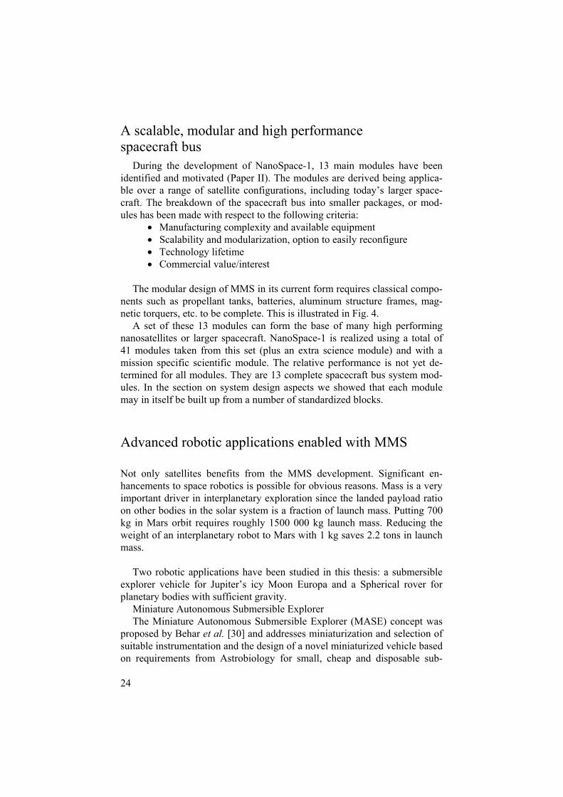
mersibles for extreme environments (e.g. narrow bore holes connecting to sub surface lakes, acid lakes, hydrothermal systems, etc.). A vehicle of this scope benefits greatly from miniaturization, packaging of electronics and instrumentation into 3-dimensional multi-chip-modules (3D-MCM). The MASE vehicle was designed to fit inside other vehicles (e.g. deep ocean mother ship, Cryobot, torpedo, etc.) and must therefore be extremely minia-turized [31]. The size of the vehicle is 23 cm in length and 5 cm in diameter.
Figure 5 shows a CAD drawing of the MEMS enabled MASE (MEM-SEMASE) concept. MMS was applied successfully to the on-board electron-ics design, enabling extremely compact fiber optical communication, motor drivers, camera, navigation, and on-board processing capabilities.
The MMS modules designed and developed for NanoSpace-1 have a square shape. A submersible that will stand high pressure and be fluid compensated is often designed like the MASE with a cylindrical shape. Figure 6 shows the layout chosen for the silicon MMS module implementation on MASE. There are many interesting applications on Earth for a submersible like MEMSEMASE. The vehicle is small enough to go into deep boreholes or autonomously investigate narrow trenches or submersed caves.
Figure 5. An illustration of the Miniature Autonomous Sub-mersible Explorer (MASE) vehicle proposed by Behar et al.

26
Spherical Mobile Investigator of Planetary Surfaces (SMIPS) The Spherical Mobile Investigator for Planetary Surface (SMIPS) concept was studied in response to a light weight rover for exploration on the Planet Mercury. The introduction of Multifunctional Micro Systems (MMS) design solutions gives the robot high performance per weight unit. The untraditional spherical shape makes it easily maneuverable and thus provides a platform for scientific investigations of interplanetary bodies. Figure 7 shows an artist impression of the concept.
Figure 7. Artist impression of the Spherical Mobile Investi-gator of Planetary Surfaces (SMIPS) enabled with MMS. Courtesy of Per Samuelsson.
Figure 6. Illustration of the silicon MMS implementation in MASE.

27
SMIPS shall be seen as a compliment to larger, wheel-based rovers which have the ability to have moving arms on the body. The main application of SMIPS is to perform long range reconnaissance for interesting areas or to collect small samples in multi-sample return or analysis missions. An impor-tant application for the future may be remote visualization at human outposts on the Moon or on Mars. Wheel-based rovers will always consume more energy than SMIPS, paper VI and VIII shows that the spherical shape to-gether with a simple locomotion principle is extremely robust.
The enabling technologies for SMIPS in terms of MMS are a multifunc-tional shell comprising solar cells and instrumentation. Microsystem tech-nologies also allow clever design of s-band communication. The importance of reducing the mass and compressing electronics are two-fold for this par-ticular system. First, reducing landed mass reducing the size of the launcher, or enables several vehicles to be deployed at the same time. The locomotion principle behind SMIPS is a simple relative movement of internal masses, thus utilizing the gravity to propel the vehicle. Putting the center of mass closer to the ground significantly increases the performance of the vehicle as it can traverse larger obstacles. It is therefore important to reduce the size of everything so that the center of mass can be lowered.
28
What about spacecraft on chip and Pico Satellite Design?
Dreams of a spacecraft on chip (SoC) are pursued by several institutions [ref, surrey 5th Round T]. My opinion is that this is to novel and doesn’t really have any real applications. A spacecraft on chip solution can be seen as an MMS module where in principle all 13 modules defined for NanoSpace-1 should be housed. It can also be seen as an ultimate application specific inte-grated circuit (ASIC). The thermal and complexity aspects of such system, together with the inherited drawbacks of not being scalable and modular put the SoC into an extremely narrow niche market. It is not clear to me today what this would be.
When it comes to Picosatellites (see appendix 2). There is probably a good market for these systems in certain niches and the thermal aspects have a good potential to be solved. Perhaps Spacecraft on Chip and Picosatellite development can be merged to create extremely miniaturized spacecraft. However, the SoC still require very complex processing and my suggestion is to use MMS. This should be much more economical since the MMS con-cept allow for ASIC’s and small System of Chip solutions to be integrated in 3-dimensional packages with very good thermal handling. MMS holds the potential on paper to cover the needs of the space community for at least the coming 15-20 years and will scale from large to picosatellites.
29
Summary of papers
Summary of Paper I: Nanospace-1: the Impacts of the first Swedish Nanosatellite on Spacecraft Architecture and Design (invited) This paper summarizes the initial design concept for the NanoSpace-1 spacecraft. It highlights the identified problem areas associated with multi-functional microsystems (MMS) design. The conceptual structure of the spacecraft is presented together with initial results from subsystem develop-ment.
Modularity and scalability is discussed in conjunction with decision trade-offs regarding reliability and redundancy.
Presentation of the central ideas for developing multifunctional microsys-tems and distributed intelligence, modularization, and functional division are identified as vital part of the suggestion methodology.
Summary of Paper II: NanoSpace-1: Spacecraft Design using Advanced Modular Architecture Advances on the NanoSpace-1 satellite from airbrush and preliminary de-signs through Phase-B design are presented in this paper. The Advanced Modular Architecture is detailed and new design tools are presented. The paper discusses a complete satellite design using MMS technologies. Important features such as scalability, distribution, and modular systems are discussed. Advanced Modular Architecture is shown to provide systems level implementation of graceful degradation, and fractional and multi-way redundancies using the tools of MMS.
30
Summary of Paper III: Spacecraft Design Optimization – A Multifunctional Microsystems Module Implementation Method Spacecraft design using a discrete set of multifunctional modules is pre-sented together with an algorithm for spacecraft optimization. The reasons for deciding and selecting various modules or configurations are presented together with definitions how MMS modules should be expressed in terms of functions. A simple design example verifies the algorithm operation.
Summary of Paper IV: Distributed Communication Architecture in Spacecraft System-of-Microsystems – A Preliminary Analysis This work presents a new distributed communication architecture for space-craft, compatible with multifunctional microsystems. A new application layer for the Controller Area Network (CAN) bus is defined, evaluated and implemented in hardware. A standardized CAN interface is designed and developed which will enable easier access and implementation on the spacecraft platform for science pay-loads.
Summary of Paper VI: MEMS Enablement of Miniature Autonomous Submersible Explorer This paper details the design of a miniaturized submersible vehicle designed for harsh underwater environment. The vehicle is very small and fits inside other vehicles. MMS enabled an increase from 2 to 6 scientific instruments and also incorporation of a high resolution real-time camera. The vehicle communicates through a bi-directional fiber optical link, which with MMS have the potential to transfer 2 W of continuous power.
31
Summary of Paper VII: A preliminary Design for a Spherical Inflatable Microrover for Planetary ExplorationThe preliminary design of a low-weight spherical interplanetary rover is presented. Analysis of key technologies such as communication antenna positioning, multifunctional shell, and navigation is detailed.Important conclusions on mission design and feasibility of new scientific mission scenarios are shown presented.
Summary of Paper VII: Extremely Low Mass Spherical Rovers for Extreme Environments and Planetary Exploration Enabled with MEMS (invited)
This paper discusses how the Spherical Mobile Investigator for Planetary Surfaces (SMIPS) can be effectively used on Mars by using direct reentry to lowering or removing the mass requirement on a Lander.

32
Appendices
TRL definition The Technology Readiness Level (TRL) scale was pioneered by NASA and is used throughout the space community to assess the level of maturity of a device or system.
The definition of TRL is given here as a reference for the reader of this thesis. The TRL scale is dived into three regions, low TRL (1-3), mid TRL (4-6) and high TRL (7-9).
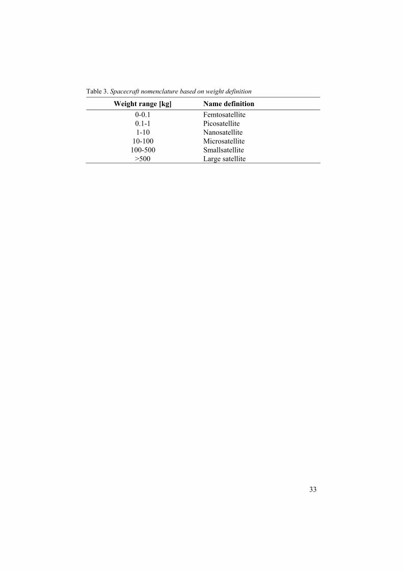
Spacecraft naming definition Spacecraft are usually named according to a mass definition. However, the mass ranges may vary from publication to publication. This thesis uses to following nomenclature.
Table 2. Technology Readiness Level definition
33
Table 3. Spacecraft nomenclature based on weight definition
Weight range [kg] Name definition 0-0.1 Femtosatellite 0.1-1 Picosatellite 1-10 Nanosatellite
10-100 Microsatellite 100-500 Smallsatellite
>500 Large satellite
34
Acknowledgements
Many people deserve my gratitude, and I therefore express this by dedicating my thesis to these worthy persons or entities. I would like to acknowledge Professor Jan-Åke Schweitz and the Center for Advanced Microengineering program (AME) for financial support and organization of the PhD student program. I am very thankful and wish to express my deepest gratitude to Professor Lars Stenmark who has been a good friend, an amazing inventor, an inspiration in business negotiations, and not the least, a flare that sets one of exploring every wild idea that come to mind. Lars as well as the entire Ångström Space Technology Centre (ÅSTC) deserves a gigantic hug for their support during my wildest moments, trying to start every possible com-pany, at the shortest possible time, and in the most disorderly fashion.
My thanks go to all my supervisors and tutors (there are a bunch of you): Jan-Åke Schweitz (ÅSTC), Lars Stenmark (ÅSTC), Johan Köhler (ÅSTC), Peter Rathsman (SSC), Gunnar Andersson (SSC), Alberto Behar (NASA/JPL), Ola Redell (KTH), Sven-Erik Jansson (IRFU), Greger (G.) Thornell (ÅSTC), Adam Baker (SSTL), and Lennart Åhlen (IRFU).
Johan Köhler and Greger Thornell deserve special attention for their re-markable speed in commenting papers, and of course, proof reading manu-scripts. Johan and Greger made this thesis possible and I cannot thank you enough.
Alberto Behar of the NASA Jet Propulsion Laboratory, a good friend and an astonishing patient man, thank you for fixing all the “nitty gritty” details requiring finger tip feeling on our various projects. Also thank you Alberto for arranging the necessary paperwork required for me to work at JPL.
Many, many thanks go to the staff at ÅSTC. You are a bunch of hard working people that would make a four star general proud. Henrik Kratz, what can I say, unbeatable. Henrik has given me many special moments worthy to remember. Peter Nilsson, my buddy in arms at NASA Jet Propul-sion Laboratory. Peter has been a great support in discussions on process development. However, don’t take all your practical jokes with you to our company. I should probably apologize to Tobias Böhnke, who had to live through my Eurodance music for a few years. I’m sorry, but I work much better listening to Techno and Eurodance.
Artist Mikael Genberg is acknowledged for his excellent illustration on the cover of this thesis, and for his visionary ideas and creations.

35
Special thanks go to Viktor Kaznov, Nils Hulth and Mats Gustafsson for your shared interest in spherical rover systems and the formation of our joint corporation Rotundus AB. I will always remember how it all started in my coach over a bottle of whiskey.
Special thanks to my dear wife, who have helped me with ground support in the most outstanding manner.
Thank you my family and relatives for your excellent support, encour-agement in various forms, and patience.
My dearest appreciation to all that I may have forgotten to thank.
Uppsala, October 25, 2005

36
Sammanfattning på svenska:Miniatyriserad multifunktionell systemarkitektur för satelliter och robotik
Min avhandling beskriver och utvärderar nanosatellitdesign uppbyggd av avancerade mikrosystem. Mikrosystemen höjer nanosatelliternas prestanda åtskilligt, och öppnar nya möjligheter för utforskningen av rymden i form av exempelvis interplanetära vetenskapliga missioner med pyttesmå rymdpro-ber. Mikrosystem, eller MEMS som de kallas med en amerikansk förkort-ning (mikroelektromekaniska system), gör extrem miniatyrisering möjlig med hjälp av arvet från elektronikindustrins processer för integrerade kret-sar. Miniatyriseringen och den därmed förknippade stora minskningen av massa och volym, sparar stora kostnader för uppskjutning av rymdfarkoster.
Jag har definierat och kategoriserat olika egenskaper och funktioner på system- och funktionsnivå i härledningen av en smidig optimeringsalgoritm för mikrosystembaserade rymdfarkoster (t. ex. satelliter). Designalgoritmen är kompatibel med de concurrent-design-metoder som används i gängse satellitdesign idag. Miniatyriseringen av de multifunktionella modulerna (MMS, Multifunctional Microsystems) ger möjligheten att konstruera modu-lära satellitarkitekturer bestående av kraftfulla, högpresterande moduler, användbara för farkoster mellan 10 och 1000-tals kg.
MMS systemen är en blandning av bland annat elektriska, termiska och strukturella funktioner som byggs upp i moduler. Modulerna består av flera ihopfogade kiselskivor som tillsammans bildar en tredimensionell pack-ningsteknik. I princip kan man säga att denna avhandling behandlar uppdel-ningen och anpassningen av olika system till dessa tredimensionella modu-ler.
Denna slags systemarkitektur har utvecklats för den svenska teknikde-monstrationssatelliten NanoSpace-1. Farkosten utnyttjar multifunktionell design för att åstadkomma distribuerad intelligens och autonomi, lindrigt förfallsförlopp av prestanda, funktionella ytor och distribuerade kraftsystem. Prestandaökningen som hänger ihop med den nya systemarkitekturen jäm-fört med konventionella och traditionella nanosatelliter går över en storleks-ordning med avseende på energilagring, masskvoten vetenskapliga instru-ment, pekstabilitet och livslängd i rymden.
37
För denna satellit har även nya metoder för distribution av dataprocess-ning och kraft definieras och flera system tilldelas autonomi. Satelliten inne-har alla funktioner som en jämförbar 200-300 kg traditionell satellit. En de-taljerad jämförelse med teknik från år 2000 visar att många system visar en tiofaldig ökning av prestanda.
Tre viktiga begrepp snor sig i en röd fläta genom avhandlingen: Modula-ritet, skalbarhet och bibehållen prestanda.
Med modularitet menas att systemen är oberoende och fristående men samverkar då de kopplas ihop. Till exempel ska kraftsystemet fungera utan att det på förhand vet hur många kraftkällor det har. I modularitet ligger även att moduler ska kunna byta plats. Detta ger upphov till individuella byggste-nar som var och en har en egen marknadspotential och som tillåter snabb montering av nya satelliter. För första gången kan man prata om kraftfulla satellitsystem som kan monteras på ett Henry-Ford-liknande löpande band.
Det andra begreppet är skalbarhet. Här avses att modulerna fungerar på en 10 kg satellit lika väl som på större, och att modulernas respektive individu-ella prestanda kan läggas ihop för att fylla skarpare kravspecifikationer.
Det sista ledordet är bibehållen prestanda och detta är ett krav som domi-nerar hela arbetet. Det innebär att de utvecklade miniatyriserade systemen ska ha samma prestanda som deras större förlaga.
Den höga prestanda som blir möjlig genom denna system-av-mikrosystem-arkitektur har också använts för designen av två rymdrobot-koncept: en miniatyriserad undervattensfarkost som ska simma omkring under isen på Jupiters måne Europa och en sfärisk rullande robot.
Undervattensfarkosten bygger på elektronikminiatyrisering med hjälp av tredimensionella vertikalt integrerade multichipmoduler tillsammans med nya anslutningsmetoder och kopplingar. Detta gör att hela farkosten ryms inom 20 cm längd och cylinderdiameter på 5 cm.
Den sfäriska roboten utvecklades för vidsträckt vetenskaplig utforskning i nätverk på främmande planeters respektive ytor. Roboten väger 3,5 kg och klarar av ett direkt inträde genom Mars atmosfär, vilket ökar kvoten mellan den landade mobila massan och massan i marsbana med en faktor 18, jäm-fört med konventionella marsbilar.
Arbetet bakom avhandlingen är genomfört vid Ångström Rymdtekniskt Centrum i samarbete med Nasa Jet Propulsion Laboratory, Kungliga Teknis-ka Högskolan, Surrey Space Technology Ltd, samt Rymdbolaget för att sä-kerställa att de designade systemen är kompatibla med befintliga system idag.
38
References
1. T. George and R. A. Powers, “Closing the TRL Gap”, Aerospace America pp24-26, August 2003.
2. T. George, E. Urgiles, R. Toda, J. Z. Wilcox, S. Douglas, C.-S. Lee, K. Son, D. Miller, N. Myung, L. Madsen, G. Leskowitz, R. El-Gammal, D. Weitekamp, “MEMS-based Micro Instruments for In-Situ Planetary Exploration,” T, Proc. SPIE 5836 188, 2005.
3. T. George, “Overview of MEMS/NEMS Technology Development for Space Applications at NASA/JPL”, Proc. SPIE 5116 136, 2003.
4. T. George, “MEMS/NEMS development for Space Applications at NASA/JPL”, Proc. SPIE 4755 556, 2002.
5. T. George, L.A. Madsen, W. Tang, A. Chang-Chien, G.M. Leskowitz, and D.P. Weitekamp, “MEMS-based force-detected nuclear magnetic resonance spec-trometer for in situ planetary exploration”, Aero. Conf. IEEE Proc. 1 273, 2001
6. S.W. Janson, H. Helvajian, and E.Y. Robinson, "The Concept of Nanosatellite for Revolutionary Low-Cost Space Systems", Paper IAF-93-U.5.573, 44th Con-gress of the International Astronautics Federation, Graz Austria, October 1993
7. J. Köhler, “Bringing Silicon Microsystems to Space - Manufacture, Perform-ance, and Reliability”. Acta Universitatis Upsalensis, ISBN 91-554-5196-9
8. P. Nilsson, M. Jönsson, L. Stenmark, “Chip mounting and interconnection in multi- chip modules for space applications”, MME '00 and Journal of Microme-chanics and Microengineering, IOP, Vol. 11, No 4, p. 339, July 2001.
9. D. M. Barnett, S. P. Rawal, “Multifunctional Structures Technology Demonstra-tion on NMP DS1”, Deep Space 1 Tech. Validation Symp. Pasadena, February 8-9, 2000
10. D. M. Barnett, S. Rawal, K. Rummel, “Multifunctional Structures for Advanced Spacecraft”, Journal of Spacecraft and Rockets, vol. 38, No. 2, March-April, 2001.
11. E. Fosness, J. Guerro, K. Qassim, S. J. Denoyer, "Recent advances in multi-functional structures," presented at Aerospace Conference Proceedings, 2000 IEEE, 2000.
12. F. C. Bruhn, F. D. Carsey, J. Köhler, M. Mowlem, C. R. German, L. Stenmark, A. E. Behar, “MEMS Enablement of Miniature Autonomous Submersible Ex-plorer”, Journal of Oceanic Engineering, vol. 30, pp. 165-178, Jan., 2005.
13. J. Sellers, L. Sauter, C. Underwood, and J. Ward, "Bounding the problem: mi-crosatellite design using commercial-off-the-shelf architecture," presented at 2002 IEEE Aerospace Conference Proceedings, Piscataway, NJ, USA, Big Sky, MT, USA, 2002.
14. B. Jackson, K. Epstein, "A reconfigurable multifunctional architecture approach for next-generation nanosatellite design," presented at Aerospace Conference Proceedings, 2000 IEEE, 2000

39
15. D. J. Hunter, "Integrated avionics system (IAS), integrating 3-D technology on a spacecraft panel," presented at 2002 IEEE Aerospace Conference Proceedings, Piscataway, NJ, Big Sky, MT, USA, 2002.
16. R. Ross and N. Atchison, Yield Modelling, in Handbook of Semiconductor Manufacturing Technology, Y. Nishi and R. Doering, Editors. 2000, Marcel Dekker, Inc.: New York, NY. pp. 851-868.
17. V. B. Menson, Yield Management, in Handbook of Semiconductor Manufactur-ing Technology, Y. Nishi and R. Doering, Editors. 2000, Marcel Dekker, Inc.: New York, NY. pp. 869-887.
18. J. R. Wertz and W. J. Larson, “Space Mission Analysis and Design”, Kluwer Academic Pub, ISBN 1-881883-10-8, 2nd Ed., 1999.
19. H. Kratz, M. Karlsson, A. Eriksson, L. Stenmark, Transmitter and Receiver Modules with Integrated Thermal Control for Spacecraft, Radio Frequency MEMS, Editura Academiei Romˆane, Series in Micro and Nanoengineering 4, ISBN 973-27-0979-0, 2003.
20. Esper, P. Panetta, M.- Ryschkewitsch, W. Wiscomabe, S. Neeck, “NASA-GFSC Nano-Satellite Technology for Earth Science Missions”, Acta Astronau-tica, vol. 46, pp. 287-296, 2000.
21. P. Panetta, J. Esper, “Enabling Technologies for Nano-Satellite Constellations”, IAF Specialists Symposium on Novel Concepts for Cheaper, Faster, Better Space Missions, Redondo Beach CA, April 1999.
22. C. Underwood, G. Richardson, J Savignol, “SNAP-1: A Low Cost Modular COTS-Based Nano-Satellite – Design, Construction, Launch and Early Opera-tions Phase”, Proceedings of the 15th Annual AIAA/USU Conference on Small Satellites, SSC01-V-1aJ.
23. S. Barabash, O. Norberg, J.-E. Wahlund, M. Yamauchi, S. Grahn, S. Persson, L. Blomberg, “Towards Low-cost Swedish Planetary Missions”, 24th Intl. Symp. on Space Technology and Science, May 30-6, Miyazaki, Japan, 2004.
24. R. Lundin, O. Norberg, M. Yamauchi, S. Barabash, S. Grahn, G. Marklund, D. Winningham, “Design and Achievements of Swedish Micro- and Nano-satellite Missions”, 22nd Intl. Symp. on Space Technology and Science, ISTS 2000-o-1-13v, Morioka, Japan, 2000.
25. A. R. Eisenman, C. C. Liebe, R. Perez, “Autonomous Rovers for Mars Explora-tion”, 1999 IEEE Aerospace Conf. Proc. Vol. 1, p.p. 237-251, 1999.
26. M. van Winnendael, B. Gardini, R. Roumeas, J. Vago, “The ExoMars Mission of ESA’s Aurora Programme”, Proc. 9th ASCE Aerospace Intl. Conf. pp. 991-998, 2004.
27. Dirk Spenneberg, Frank Kirchner (2002). SCORPION: A Biomimetic Walking Robot. In Robotik 2002, No. 1679, pp. 677–682.
28. D. Spenneberg, M. Albrecht, T. Backhaus, J. Hilljegerdes, F. Kirchner, H. Zschenker, “ARAMIES: A Four Legged Climbing and Walking Robot”, 8th Intl. Symp. Artificial Intelligence, Robotics, and Automation in Space, 5-8 Sept. Munchen, 2005.
29. Helvajian, H., Janson, S. W., “Microengineering Space Systems”, Microengi-neering Aerospace Systems, The Aerospace Press, 1999.
30. A. E. Behar, F. C. Bruhn, F. D. Carsey, “Exploring Miniaturization Limits for an Instrumented Autonomous Submersible Explorer for Extreme Environ-ments”, Accepted to 13th Int. Symp. on Unmanned Untethered Submersible Technology, 2003.
31. W. Zimmerman, F. Anderson, F. Carsey, P. Conrad, H. Engelhardt, L. French, M. Hecht,“The Mars’07 North Polar Cap Deep Penetration Cryoscout Mission“, Proc. Aerospace Conf., IEEE, Vol. 1, 305-315, 2002.