v, i, r measurements: how to generate and measure...
TRANSCRIPT

V, I, R measurements: how to generate and measure quantities and then how to get data
(resistivity, magnetoresistance, Hall).
November 14, 2008
590B
Makariy A. Tanatar
Thermo- galvano-magnetic effects
Seebeck effect
Hall effect
Weak field magnetoresistance

Thermoelectric effectsSeebeck effectPeltier effect (heating/cooling on current flow in contacts)Thompson effect (heat/cooling in materials with current and T-gradient)
Thermo- Galvano- magnetic effects (electrical and heat current carrying conductor in magnetic field)Longitudinal and transverse with respect to the current
LongitudinalOrbital magnetoresistance
TransverseHall effectNernst effect (transverse voltage with longitudinal heat current)Ettingshausen effect (transverse temperature gradient)
And many more! (32 possible combinations!)
A little bit of classification
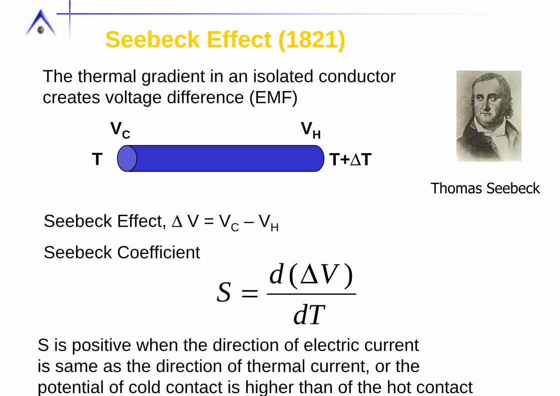
Seebeck Effect (1821)
Seebeck Effect, ∆ V = VC – VH
Seebeck Coefficient
The thermal gradient in an isolated conductor creates voltage difference (EMF)
T+∆TT
VC VH
dTVdS )(∆=
Thomas Seebeck
S is positive when the direction of electric current is same as the direction of thermal current, or the potential of cold contact is higher than of the hot contact

Thompson Effect
When current flows in a homogeneous conductorwith thermal gradient extra heat is absorbed/released
T+∆T, QTI=0
T+∆T, Q± ∆QTI=0
TQ
∆=β
Thompson coefficient
William Thomson (Lord Kelvin)
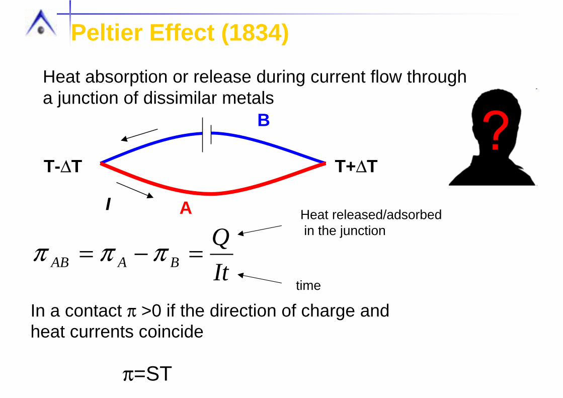
Peltier Effect (1834)
Heat absorption or release during current flow through a junction of dissimilar metals
A
B
T-∆T T+∆T
I
In a contact π >0 if the direction of charge and heat currents coincide
ItQ
BAAB =−= πππHeat released/adsorbedin the junction
time
π=ST

Mott formula for thermopower
FeTkS B
εεεεσπ
=⎟⎠⎞
⎜⎝⎛
∂∂= )(ln
3
22
⎥⎥⎦
⎤
⎢⎢⎣
⎡
−
−+⎟
⎠⎞
⎜⎝⎛
∂∂=
∫∫ −
= )()())((
)())(()(ln3
122
kvkvkdk
kMkdkeTkS
F
FB
Fεεδ
εεδε
ετπεε
)()())((4
)()( 32 kvkvkdke F εεδ
πετεσ −=
transport thermodynamic
Difficult to understand in general case
jiij kk
kM∂∂
∂±=− )(12
1 εh Inverse of effective mass tensor

Simple cases “good scattering”
Isotropic Fermi surface
Impurity scattering and T>>ΘD
Here scattering does not have sharp energy dependence
⎟⎠⎞
⎜⎝⎛ += ςπ
23
3
22
F
B
ET
ekS
ςετετ 0)( =
Diffuse thermopower of free electron gas
The better the metal, EF↑ and S↓
F
BB
ETk
ekS ~ kB/e=87 µV/K, characteristic thermopower unit
In metals S<<kB/e
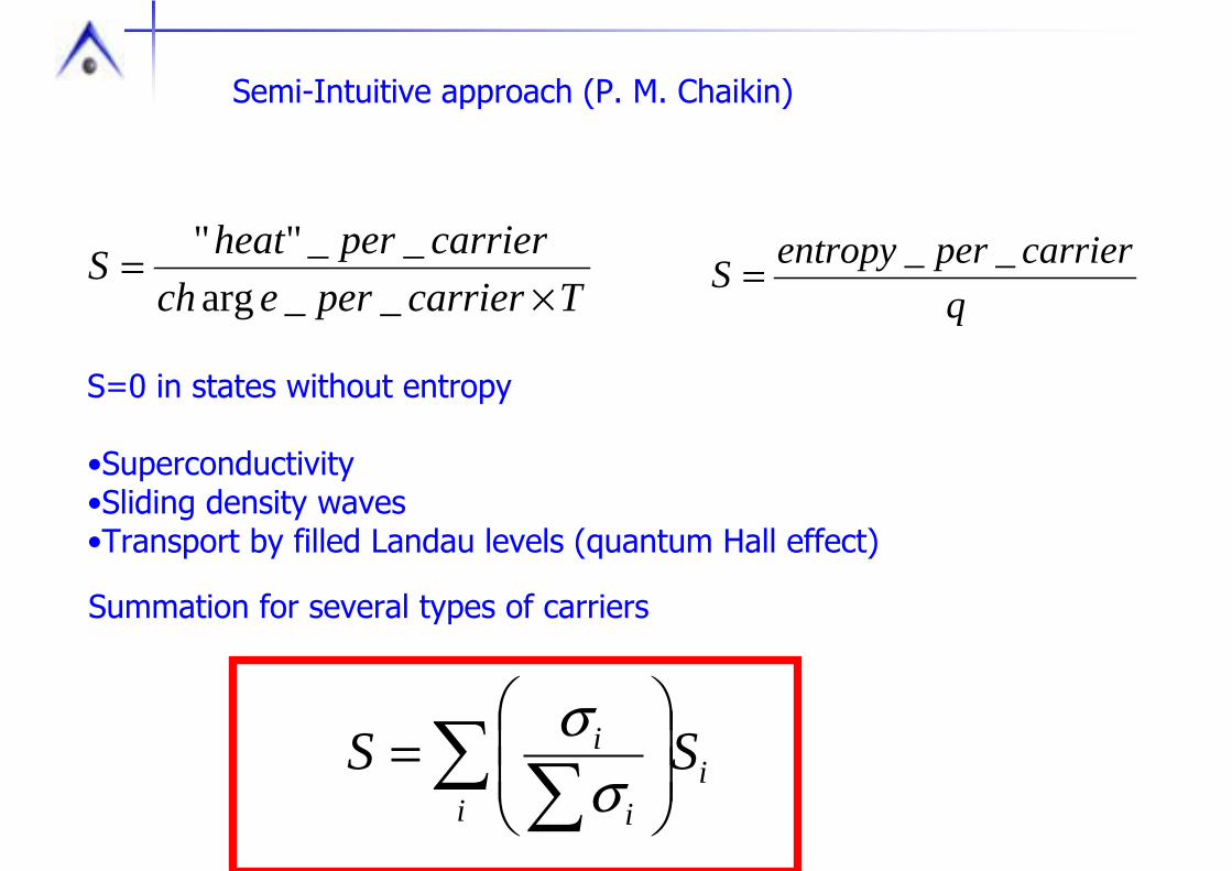
Semi-Intuitive approach (P. M. Chaikin)
qcarrierperentropyS __=Tcarrierperech
carrierperheatS×
=__arg
__""
S=0 in states without entropy
•Superconductivity•Sliding density waves•Transport by filled Landau levels (quantum Hall effect)
Summation for several types of carriers
∑ ∑ ⎟⎟⎠
⎞⎜⎜⎝
⎛=
ii
i
i SSσ
σ
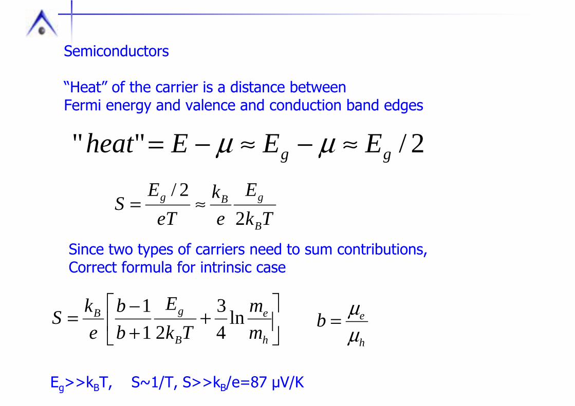
Semiconductors
“Heat” of the carrier is a distance between Fermi energy and valence and conduction band edges
2/"" gg EEEheat ≈−≈−= µµ
Since two types of carriers need to sum contributions, Correct formula for intrinsic case
TkE
ek
eTE
SB
gBg
22/
≈=
⎥⎦
⎤⎢⎣
⎡+
+−=
h
e
B
gB
mm
TkE
bb
ekS ln
43
211
h
ebµµ=
Eg>>kBT, S~1/T, S>>kB/e=87 µV/K

Thermopower of polarons
Interesting difference between resistivity and thermopower
In both semiconductor and polaron transport resistivity is activated
S=1/T in the first case, S~T in the second
Why? Energy diagram
IntrinsicSemiconductor
µ
Polaron
µ
In polaronic case there is no change of energy betweenInitial and final statesS is small

Why bother measuring thermopower?
•Information on charge of carriers (not many ways to get!)
•Information of carrier density (indirect)
•Can distinguish cases of real gap and mobility gap
•Can distinguish intrinsic and impurity dominated transport
•Extreme sensitivity to superstructures and short range orderings
These produce anomalies in energy derivative of conductivity
εεσ
∂∂ )(
Supercondcutors, S=0
Lead (S<0.2 µV/K in all range <300K), frequently used for High-T calibrations
Phosphor bronze (recent development) S~0 (<1 µV/K at 300K, <0.1 µV/K at 20K and below)Does not depend on magnetic field
Thermocouple materials Constantan-37 µV/K at room temperatureChromelType E thermocouple
Some useful materials for thermopower measurements

4-probe thermopower measurements
T+∆T T
VC VH
Q
The problem:∆T is not only in the sample, but in the measuring circuit
Inevitably pick up wire loop thermopower
Ways around:Do not let gradient escape into external wiresClose the loop thermally
Inside the measuring loop use wires with well documented behaviorS=Ssample+Swire(addenda)
V
∆T
∆Tex=0
Best way: superconducting wires
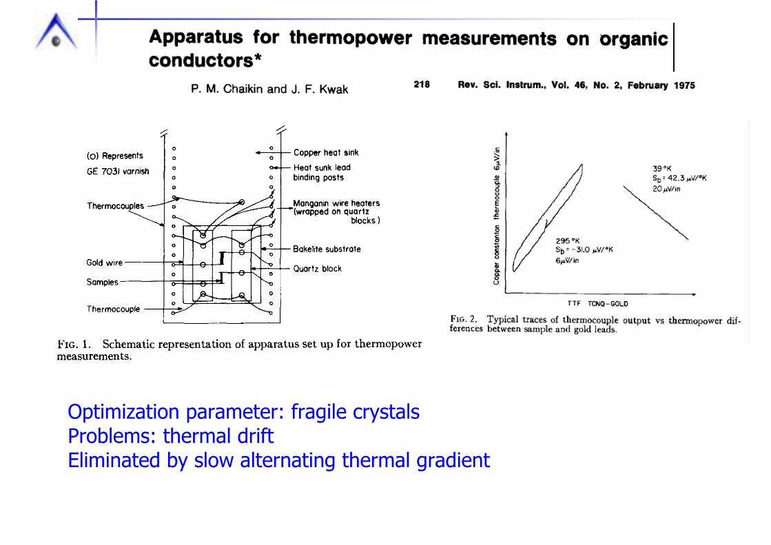
Optimization parameter: fragile crystalsProblems: thermal driftEliminated by slow alternating thermal gradient


Thermopower under pressure
BothType E and AuFe-Au thermocouples are not very sensitive to pressure
Pressure medium establishesThermal gradient,Prohibitive to materials with very high thermal conductivity
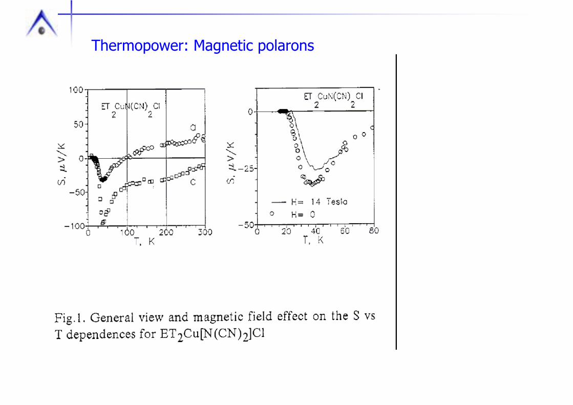
Thermopower: Magnetic polarons

Thermopower: Tallon formula
Advantage: all transport varies with doping, Only S does not depend on geometric factor!
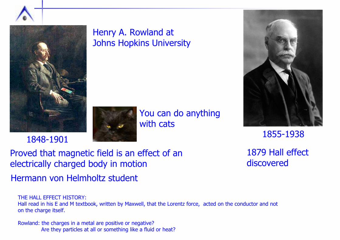
Henry A. Rowland at Johns Hopkins University
1879 Hall effect discovered
1855-19381848-1901Proved that magnetic field is an effect of an electrically charged body in motion
Hermann von Helmholtz student
THE HALL EFFECT HISTORY:Hall read in his E and M textbook, written by Maxwell, that the Lorentz force, acted on the conductor and not on the charge itself.
Rowland: the charges in a metal are positive or negative? Are they particles at all or something like a fluid or heat?
You can do anythingwith cats

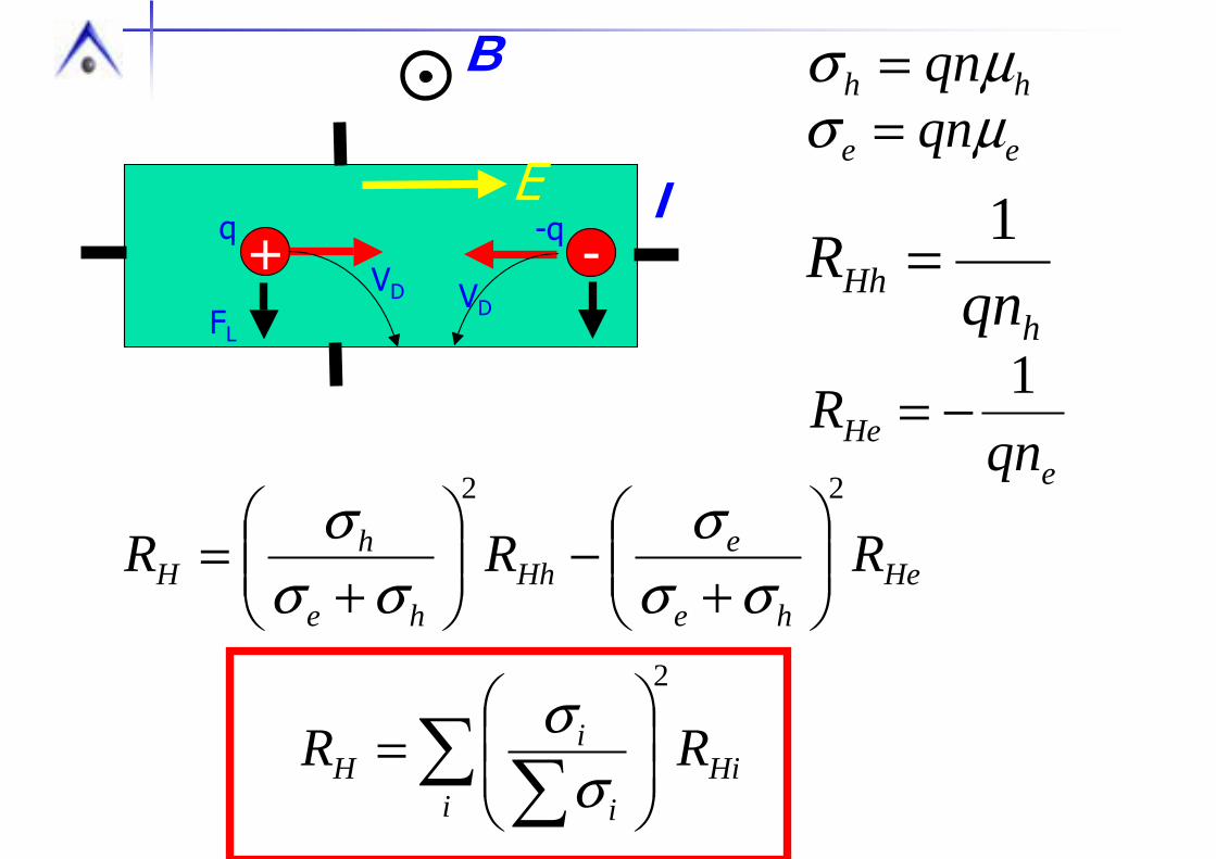
A magnetic field B is employed perpendicular to the current direction j, a potential difference (i.e. a voltage) develops at right angles to both vectors.
A Hall voltage UHallis measured perpendicular to B and j
q · (vD × B) =FL
Charge moving in magnetic feild
vD = µ · E, µ = mobility of the carriers

•Sign of charge carriers•Concentration and mobility of charge carriers (in combination with resistivity)•Hall magnetic field sensors (one of the most precise and linear)•Anomalous Hall effect is used to detect magnetic transitions
B
dIBRU HH =
+VD
q
FL
EH
qEH=qVDB
I
+
-
UH=EHw
EH=µELB
µσ qn=
qnRH
1=
Here q is elementary charge ±electron
Good for:
E
B
I+ VD
q
VD
-q-
FL
E
hh qnµσ =ee qnµσ =
hHh qn
R 1=
eHe qn
R 1−=
Hehe
eHh
he
hH RRR
22
⎟⎟⎠
⎞⎜⎜⎝
⎛+
−⎟⎟⎠
⎞⎜⎜⎝
⎛+
=σσ
σσσ
σ
∑ ∑ ⎟⎟⎠
⎞⎜⎜⎝
⎛=
iHi
i
iH RR
2
σσ

Limitations: •Hall effect is a quantitative tool at low fields where it is linear•In materials with simple and well understood band structure•When you have no magnetism
Other cases: still useful tool, if you understand limitations!Difficult to make definite statements
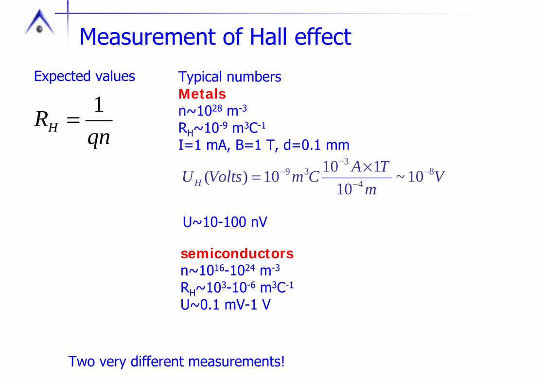
Measurement of Hall effect
qnRH
1=
Expected values Typical numbers Metals n~1028 m-3
RH~10-9 m3C-1
I=1 mA, B=1 T, d=0.1 mm
Vm
TACmVoltsUH8
4
339 10~
1011010)( −
−
−− ×=
U~10-100 nV
semiconductorsn~1016-1024 m-3
RH~103-10-6 m3C-1
U~0.1 mV-1 V
Two very different measurements!

Hall effect sample
VR+
VR-
VH
I+
I-
dIBRU HH =
Usually measure not UH
dBRR Hxy =
but Hall resistance Rxy=UH/I
Ideal samplegeometryHall bar

Measurements
Hall resistance is defined as odd part of Rxy in field
Rxy=Rnonequipotential+RMR+UH/I
Measurements in positive and negative fields, Rxy(H)-Rxy(-H)=2UH/I
Ideal case: fixed temperature +H to –H sweepIn reality frequently 2 fixed fields if want T-dependenceTime consuming
Strict requirements for T-drift, Rxy(δT)<<Rxy(H)
Option: sample rotation in magnetic field ( I used in my measurements)Quick field direction reversal, sometimes impossible (magnetic, SC samples)

Exotic ways to measure: Double frequency modulation, use AC magnetic field and AC current
])sin[()sin()sin(
0
0
0
tVVtIItBB
BI
I
B
ωωωω
±===
Very good but sophisticated technique demanding for EM interference
Several text books on methods of measuring Hall effect
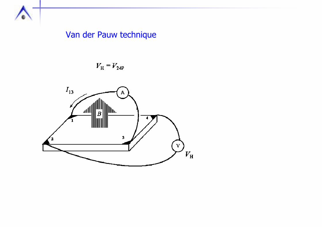
Van der Pauw technique

Canonical behavior“good scattering”
Metals RH=const(T)SemiconductorsRH=exp(1/T)
CupratesRH=1/T
Anomalous behaviorIs found quite frequently
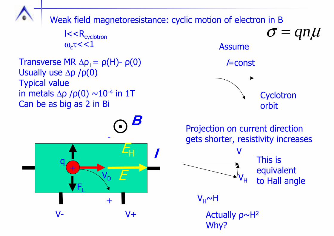
B
+VD
q
FL
EH I
+
-
E
V+V-
Projection on current directiongets shorter, resistivity increases
l=const
Assume
Cyclotron orbit
Weak field magnetoresistance: cyclic motion of electron in B
This is equivalentto Hall angle
V
VH
VH~H
Actually ρ~H2
Why?
l<<Rcyclotronωcτ<<1
Transverse MR ∆ρ⊥= ρ(H)- ρ(0)Usually use ∆ρ /ρ(0) Typical valuein metals ∆ρ /ρ(0) ~10-4 in 1TCan be as big as 2 in Bi
µσ qn=

B
+VD
q
FL
EH I
+
-
E
V+V-
Weak field magnetoresistance
This is equivalentto Hall angle
V
VH
VH~H
The trajectory is cyclotron orbituntil Hall voltage sets in
Transverse electric field makes it straight again
If no cyclotron motion, why MR?
µσ qn=

Kohler ruleFor “good scattering” transverse MR is universal function
)(0
efHF=∆ρρ
0
)(ρ
ρ THHef =
The data for same metal are on the same line
Heff is actually the measure of m.f.p./Rcyclotron
Distribution of velocities.
Hall field compensates only average velocity VD
Hot and cold carriers still have bent orbits
Effect becomes second order ~H2, much weaken than it could be
µσ qn=
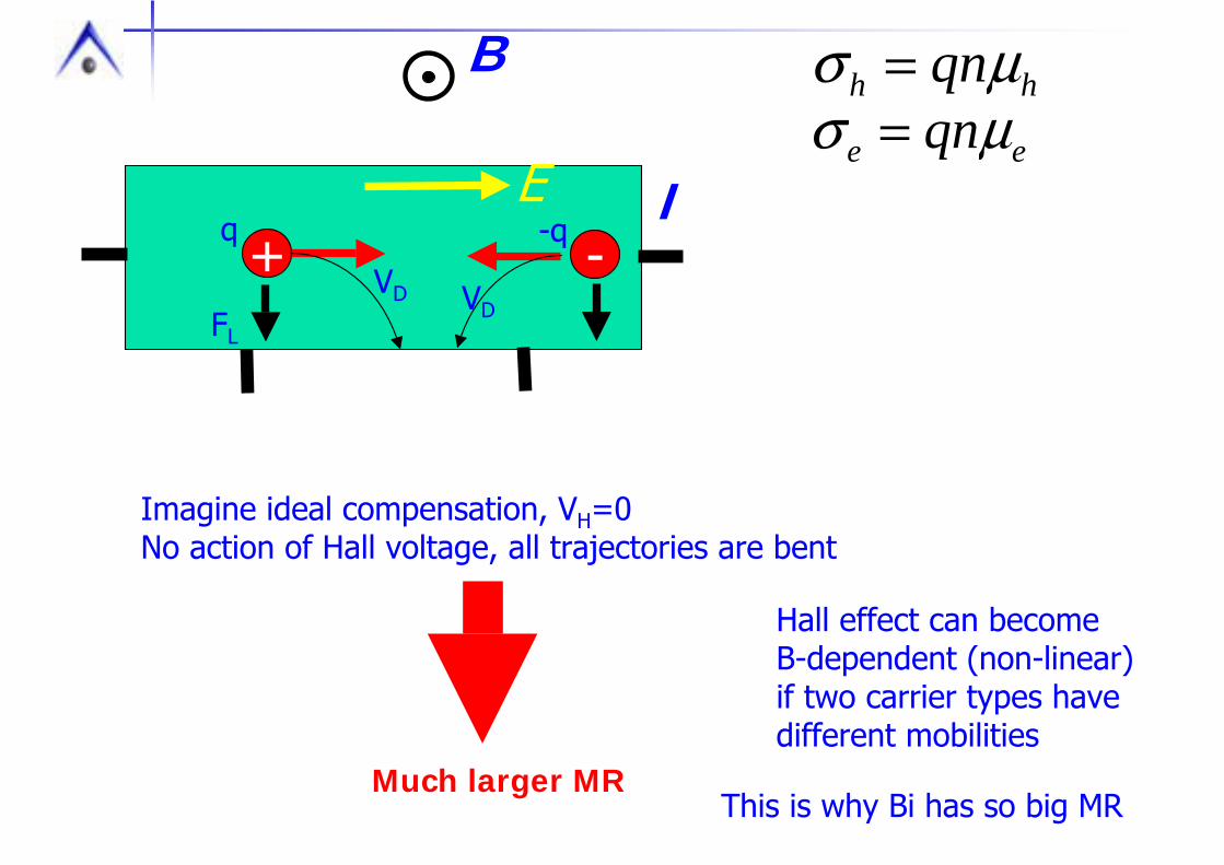
B
I+ VD
q
VD
-q-
FL
E
hh qnµσ =ee qnµσ =
Imagine ideal compensation, VH=0No action of Hall voltage, all trajectories are bent
Much larger MR
Hall effect can become B-dependent (non-linear)if two carrier types have different mobilities
This is why Bi has so big MR

Instead of making assumptions on number of carriers and their mobility,assume these as variables. Analysis analogous to Fourier transformation
Mobility spectrum analysis technique
Need relatively big magnetoresistance to apply

P. M. Chaikin, An introduction to thermopower for those Who Might wantTo use it to Study Organic Conductors and SuperconductorsOrganic SuperconductivityBy Vladimir Z. Kresin, William A. Little
http://books.google.ca/books?id=K5UDM5rkxNYC&pg=PA101&lpg=PA101&dq=chaikin+kresin&source=bl&ots=cxY3M39HbU&sig=6I0NtnwSRJoCRaMXVagFGS_gEP0&hl=en&sa=X&oi=book_result&resnum=1&ct=result
N. P. Ong, GEOMETRIC INTERPRETATION OF THE WEAK-FIELD HALL CONDUCTIVITY IN 2-DIMENSIONAL METALS WITH ARBITRARY FERMI-SURFACEPHYSICAL REVIEW B43, 193-201 (1991)