v-ray & maxscripting physical camera exposures · in 3d studio max there are two sets of lights...
TRANSCRIPT

V-Ray & Maxscripting Physical Camera
Exposures
HDRI Lighting Method utilising Maxscript to automatically calculate V-Ray Physical
Camera settings for Interior Scenes.

Welcome This knowledgebase document has been written to highlight my research and development of a
scripted calculation process aimed at physically balancing an interior scene in AutoDesk 3D Studio
Max lit by HDR files and automatically calibrating V-Ray physical cameras using standard lighting
metering methods.
The purpose of this paper is to provide designers with a script that will significantly reduce guess work
when rendering interior scenes using V-Ray. There are many on-line resources explaining workflows
using HDRI techniques, but not many provide an actual definitive answer to the question of ‘What are
the ideal settings’. The answer is, in my opinion, that there are no ‘ideal’ settings, no cheat-sheet as it
were.
One must over time develop a sense of artistry and understanding, which in some folk’s lives is too
long a time. Therefore I have set-out throughout this document a time saving, informative workflow
that should help designers to achieve realistic results relatively fast.

Template Scene Sourcefile;
You can obtain the scene used in this paper here: Exercise_File.Rar The file was created in AutoDesk 3D Studio Max 2014 x64 using V-Ray Adv 2.40.04.
Note: I always work in millimetres and to follow this paper you should too. When opening the file
adopt the incoming file units, otherwise the lighting scale may return incorrect results. You can refer
to my website for a brief tutorial regarding how to set V-Ray up in Max for the most optimal rendering
results.
Maxscript;
You can find the script in the resource section at the end of this document. Please note whilst I offer
this script for free, remember this, I developed this script after much research and hours of testing, so
please, if you can provide a link back to my website, or even better, leave a comment on my site.

Introduction to this Workflow There has always been a large gap between artist’s workflows when it comes to rendering. I remember
when V-Ray Physical Cameras were introduced. Even to this day there is a significant lack of on-line
documentation highlighting each of the settings and the end results. I put this down to a number of
reasons, mainly being a fundamental need to get the job done.
If it were the case that V-Ray Physical Cameras were the single control point of how a render is
finished then this document would not exist. Instead it is the delicate balance between VRPC’s (V-Ray
Physical Cameras), V-Ray global render processing setting and the methodology of the scenes lighting.
These three main elements are what I believe to be a deterrent. Designers simply become frustrated or
once more have not the time to ‘sit and play’.
6 months ago I started to conceptualise a method of automatically generating camera and scene
exposure control settings based on a template file that can be freely edited to achieve realistic results.
Moreover this needed to be a Maxscript that would take in to account industry standard data and
make it applicable to the 3D Studio Max scene.
Much research as carried out in two main areas, HDRI (High Dynamic Range Imagery) and
Photographic Exposures.

Working With Daylight Factors The term Daylight Factor is a calculated numeric value that is derived from the amount of
illumination present inside a room (Ei) relative to the amount of illumination present outdoors (Eo),
measured together at the same time.
The Daylight Factor is one of the most common metric used when studying physical models to test
daylighting designs.
The Daylight Factor (DF) is calculated by dividing a captured reading within a room at a certain work
surface height (Meter Reading) by that of an external reading captured and then multiplied by 100.
Here is the formula.
DF = (Ei / Eo) x 100
Where:
Ei = Daylight Illuminance at a working surface indoors
Eo = Simultaneous outdoor illuminance of an unobstructed horizontal plane
Ei has to be calculated by the architectural structural openings available in your scene, either from a
window or skylight or other external façade opening. The particular characteristics of how light
penetrates the room create the basic of Ei which are:
Direct light from a patch of sky visible at the point considered, known as the sky
component (SC)
Light reflected from an exterior surface and then reaching the point considered, known
as the externally reflected component (ERC)
Light entering through the window but reaching the point only after reflection from an
internal surface, known as the internally reflected component (IRC)
The sum of these three components will give us an illuminance level (Lux) of the interior space in the
direction the camera is targeted. The Lux is incredibly important as we require this to calculate the
photographic settings for the V-Ray camera based on exposures.
In the script I have written Ei is represented as a V-Ray Light Meter Helper called Internal
Component. Eo is equally a V-Ray Light Meter Helper named Sky Component.

Check the Daylight Intensity Table below for such values.
In this particular scene it is important to remember that the main lighting source is a VRay Dome light with a HDRI assigned to the emit slot. Here is a preview of the file:
This is an example of a LDR, a Low Dynamic Range image. There is very little colour depth, however there are ample amounts of tonal range. This tonal range is what will produce interesting shadows and
light casting shapes on to our scenes geometry.

Working with Exposures Now we have a brief understanding of Daylight Factors, we can now take a look at Camera Exposures.
EV corresponds simply to a combination of a shutter speed and an aperture setting, independent of
any ISO setting—independent even of whether there is film in the camera or any light available.
EV is dependent upon two key camera functions with a scene of fixed illuminance:
Shutter Speed
F-Number
I highly suggest using http://www.pixel-peeper.com/ to view a cross section of photographic exposure
examples. This will broaden your knowledge of photographs shot in alternate situations.
Although all camera settings with the same EV nominally give the same exposure, they do not
necessarily give the same picture. The f-number (relative aperture) determines the depth of field, and
the shutter speed (exposure time) determines the amount of motion blur.
Exposure times, in seconds or minutes (m), for various exposure values and f-numbers
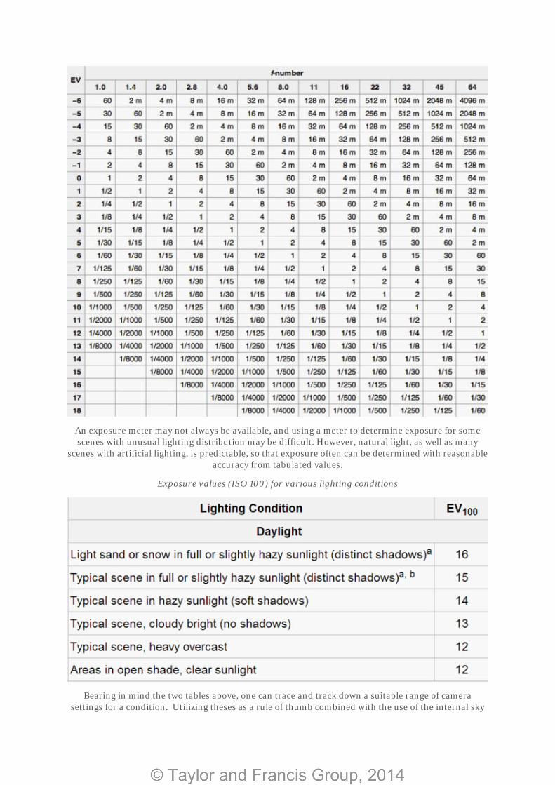
An exposure meter may not always be available, and using a meter to determine exposure for some scenes with unusual lighting distribution may be difficult. However, natural light, as well as many
scenes with artificial lighting, is predictable, so that exposure often can be determined with reasonable accuracy from tabulated values.
Exposure values (ISO 100) for various lighting conditions
Bearing in mind the two tables above, one can trace and track down a suitable range of camera settings for a condition. Utilizing theses as a rule of thumb combined with the use of the internal sky

component and the external sky component meter readings we should be able to process a realistic scene.

Running the Script In the template file you will find an interior scene with a selection of complex meshes and reflective
materials. There are two doors enabling ample amounts of light to spill in to the room.
Note the placement of the two V-Ray light meter reading helpers.
The image above shows a wireframe view of the scene. Inside the room is the internal_component V-
Ray light meter helper and on the outside of the room is the sky_component V-Ray light meter helper.
These both represent our Ei and Eo values (once calculated).
In order to achieve a realistic result we need to enter some basic values in coordination with the EV
chart. We have a daytime scene which has tangible light so we can go ahead and enter a corresponding
f-number in the V-Ray Exposure Control dialogue box.
Notice that I am not using V-Ray Physical Cameras in my view-port. I do not need to as I have
activated the global settings in the Environment settings (8 on your keyboard).
Here the script is programmed to update these settings when calculated.
To begin with I have entered an f-number of 2.0 and an ISO of 6400.

When I execute the script it will calculate the Shutter Speed based on the Daylight Factor illuminance
cast from the HDRI file.
The internal_component and sky_component are calculated and returned as numeric arrays. Here we
can take an average from both calcs to determine the mean value. Here is a test render of the scene.
As you can see the scene is over bright but realistic enough to be believable. Notice the way the
shaders are functioning and returning improper results. Let’s take a look at the zoomed in camera
also, here is the rendered result:
You can change the f-number up and down to achieve a better more realistic outcome. The Shutter Speed will always automatically change to suit.
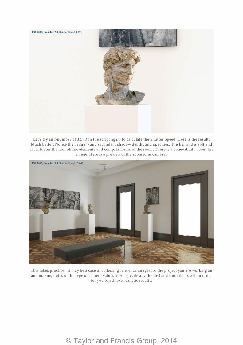
Let’s try an f-number of 3.5. Run the script again to calculate the Shutter Speed. Here is the result: Much better. Notice the primary and secondary shadow depths and opacities. The lighting is soft and
accentuates the monolithic elements and complex forms of the room. There is a believability about the image. Here is a preview of the zoomed in camera:
This takes practice. It may be a case of collecting reference images for the project you are working on and making notes of the type of camera values used, specifically the ISO and f-number used, in order
for you to achieve realistic results.

This may seem like trial and error, however at least you have a tool-set to work from instead of
perhaps guessing.
This scene has been calculated using only natural light, photometric lights can be added after the
calculation is complete of the Ei and Eo values.

Photometric Lights Photometric lights are a digital tool-set for lighting scenes based on real-world parameters. These
parameters can come from the manufacturers themselves in the form of .ies files or distribution files.
Our template scene is at a stage where the natural daylight is balanced enough with the correct camera
settings, but lacks depth. This depth can be added by including spotlights to the scene as key fill lights.
Directional lights will bring out all the hidden details contained within shaders that have bump or
displacement maps, as well as affecting the specular of shaders with high or semi reflectance levels.
Often it can be the cast that when rendering using HDRI methods alone, minimal detail is highlighted
given the fact that the light is usually blurred due to the low dynamic range of the HDRI file.
In 3D Studio Max there are two sets of lights that you can use. Either the V-Ray IES or the
Photometric lights that come with Max. In my experience and in my opinion you should use the
Photometric ones that come with Max. The main reason being is that you have much more control
over the properties of the light. The V-Ray IES light is incredibly basic and tends to wash the scenes
out with the temperature of the light.
If we maintain the previous render settings combined with camera settings and proceed to add 4 or 5
Photometric lights we can see the dramatic difference this will have.
You can simply right click and unhide all, the lights should appear. There are many on-line resources
for photometric file downloads. I would recommend you use the manufacturers such as ERCO or
Phillips. I have included a list in the resources section.
For now you can go ahead and produce a render of the scene with the spotlights lights active. Here is
the result:

By methodically processing the scene beginning with natural daylight, it is much easier to set up the
artificial light to see the incredible contrast. Furthermore I prefer to keep the photometric values away
from my script shutter speed calculation as the values can be out.
Finally a zoomed in camera view showing results of reflections from the photometric lights.
From here it is incredibly easy to alter the temperature and light casting properties by simply choosing a different .ies file. Adjusting the colour filter in the temperature roll out is also simple.

V-Ray Lens Effect The VRayLensEffects is a render effect plugin used to simulate bloom and glare lens effects by filtering
the rendered image with a kernel filter. It is relatively simple to use especially given the workflow and
type of scene this document is tailored to.
It is activated in the Environment and Effects panel (8 on your keyboard).
You can activate the Bloom and Glare parameters within the roll-out and update the scene. It is
important that you use the built in V-Ray frame buffer. Here is what Chaos Group say:
When using the V-Ray VFB, VRayLensEffects will be able to handle properly any colour mapping
applied to the image by computing the bloom and glare based on actual linear data, and then applying
the colour mapping to the final result. To achieve this, VRayLensEffects creates internally a render
element called LensEffectsSource, which contains the linear colours. When using the 3ds Max frame
buffer, this is not possible. In that case, it is recommended to render in linear colour space and apply
any colour mapping as a post-process.
If you are setting the VRayLensEffects up once you have finished editing your scene you can simply
use the ‘update effect’ button. If not the scene will render again. I simply use the Image and Render
Element option in the Bloom section. The Glare settings can be changed to accommodate a selection
of ‘From Camera Parameters’ and ‘Image and Render Element’ as the mode.
Firstly let’s look at the render with Bloom enabled only:

Here you can see a slight bloom phenomenon added to the render. You can control this with relative
ease using the Update Effect button.
Now let’s look at the effects of Glare only.
The Glare effect is incredibly effective especially for scenes that use HDRI as the primary lighting technique. The two effects combined produce the following:
The delicate balance between these two filters will need to be mastered in order to produce a realistic
result. This of course takes practice.

With the simple auto tone filter in Adobe Photoshop you can turn any of the images produced in this
document in to a unique set of renders. But it is not only Photoshop that is suitable for adjusting and
correcting the image properties, the V-Ray frame buffer is incredibly powerful and easy to use.
Here is the same frame with a simple Autotone modifier applied in Adobe Photoshop.

Resources HDRI Resources
http://www.hdrlabs.com/sibl/archive.html
http://www.openfootage.net/
http://www.pauldebevec.com/
http://www.openexr.com/
Photometric Resources
http://www.erco.com/products/indoor/overview-5760/en/
http://www.artemide.com/home/index.action
http://www.usa.lighting.philips.com/connect/tools_literature/photometric_data_1_b.wpd
http://www.tomdixon.net/products/lighting

V-Ray Physical Camera Scene Calibration Script
Copy and paste the following script in to your Maxscript editor. (c) Lee Wylde 2014
/**
* Function definitions
*/
– Sum an array
function arraySum arr =
(
local sum = 0
for i in arr do (
sum += i
)
sum
)
– Calculate the mean value in a numeric array
function arrayMean arr =
(
local sum = arraySum arr
sum / arr.count
)
– Get the average value of VRayLightMeter points
function lightMeterAverage &vrayObject =
(
arrayMean vrayObject.total
)
– Convert ev to lux
function evToLux ev =
(
2.5 * 2 ^ ev
)

– Convert lux to ev
function luxToEv lux =
(
log(lux / 2.5) / log(2)
)
– Calculate the optimal shutter speed from ev
function shutterSpeedFromEv ev =
(
(2.0 ^ (ev as float * -1)) * (SceneExposureControl.exposureControl.f_number ^ 2)
)
/**
* Script begins here
*/
$internal_component.Calculate()
$sky_component.Calculate()
Ei = lightMeterAverage $internal_component
Eo = lightMeterAverage $sky_component
lux = Ei/Eo * 101
ev = luxToEv lux
ss = shutterSpeedFromEv ev
SceneExposureControl.exposureControl.Shutter = ss
Conclusion
This experimental research post has been written for users to familiarise themselves with alternate
tool-sets in order to achieve realistic results in Autodesk 3ds Max. This is no the only way to achieve
realism in scenes however it may help you.