v setting up new machining centersetting...
TRANSCRIPT

Procedure for preparing new MC
――――――――――――――――――――――――――――――――――――――――――――― PCadCam International (PCI) 1
VVVV
SETTING UP NEW MACHINING CENTERSETTING UP NEW MACHINING CENTERSETTING UP NEW MACHINING CENTERSETTING UP NEW MACHINING CENTER
for for for for PCadCam2000 PCadCam2000 PCadCam2000 PCadCam2000
There are three important setup preparations of PCadCam2000 software to run on a new
machining center. They are:
1. Data preparation for CAM database.
This includes:
1-1. Machine Name database
1-2. Machine database
1-3. Tool pod database
1-4. Controller database
1-5. Index table database (for five axes machining or using an index table on
vertical or horizontal M/C).
2. Preparation of sub-program registration on the machine.
This includes:
2-1. Tool change sub-program
2-2. Ending operation sub-program
2-3. FXO sub-program
2-4. Index table sub-program (for five axes machining or using an index table on
vertical or horizontal M/C)
3. Setting up fixture origin point (for external setup only)
Setting up fixture origin point is different based on the type and usage of the machine
or the type of its controller such as FANUC, YASNUC, MELDAS, OSP, etc. The following
will explain a concrete example.
User should decide the following items on the machining center before starting any
operation.
1. Decide the data symbol for machine name and controller name.
2. Decide a T-number for dummy tool in tool pod setting to provide one that allocates
a dummy condition of spindle.
3. Check if the machine is capable to do helical interpolation.
4. Check if the machine controller utilizes common variable on sub program. If YES,
check from which number that it can be used.
5. Read carefully P-CAD/CAM manual section 4.2.2.5 (Controller Database), and

Procedure for preparing new MC
――――――――――――――――――――――――――――――――――――――――――――― PCadCam International (PCI) 2
prepare to input the code to be used for machine controller.
6. Decide the data symbol for material types on normal machining condition.
In the mean time, install the tool data and machining method database belong to TUT.
While using the database, user can modify the data to create their own unique database.
5.1. Data Preparation inside CAM Database
5.1.1. Machine Brand Database Preparation
Input “1” for machine brand ID and input “common” value for machine name and machine
type. Also type other data as shown in Figure 5-1.
Figure 5-1. Dialog box of machine brand data example for Common machine
Do not erase nor edit any data with “common” value. These data are crucial for
automatic operation of data management. User should register machine brand ID started
with “2” to create a different data.

Procedure for preparing new MC
――――――――――――――――――――――――――――――――――――――――――――― PCadCam International (PCI) 3
Figure 5-2. Dialog box of machine brand data example for Enshu machine
The above Figure 5-2 is an example for ENSHU vertical machining center. The machine
uses YASNUC controller as the NC control device.
There are three alternatives for T-Code numbering for user to decide.
In the next Okuma horizontal machining center example as shown in Figure 5-3, a “Fixed
T Code” is selected to create a fixed T-number for each tool in the production plant,
and also to match the T-Code and H-Code since up to four digits H-Code address could
be applied for tool length compensation data.
Figure 5-3. Dialog box of machine brand data example for Okuma machine

Procedure for preparing new MC
――――――――――――――――――――――――――――――――――――――――――――― PCadCam International (PCI) 4
5.1.2. Machine Database
Input “1” for machine ID and input “common” value for machine name and Machine brand.
Also type other data as shown in Figure 5-4.
Figure 5-4. Dialog box of Common machine data
Figure 5-5. Dialog box of Enshu 1 machine data
The above Figure 5-5 is the machine dialog box for a machine called Enshu. There

Procedure for preparing new MC
――――――――――――――――――――――――――――――――――――――――――――― PCadCam International (PCI) 5
are two units of Enshu machine in one of the user's plant; the first one is registered
to be Enshu 1. In the example, T145 is given to Dummy Tool ID, which sets a tool number
T145 when no tool exists (dummy) on machine spindle after ATC operation.
Sub-program number 6000 is for the tool changing sequence and 6001 is for ending
machining sequence sub program. Both of these two programs are machine resident
sub-program. Program number 52 is assigned to shift the coordinate from FXO (fixture
origin point) to NCPR (NC program reference point) sub program. There is a “-“ sign
ahead of number 52. When this mark is given; for example on vertical MC equipped with
the X-rotational axis of workpiece index device or on horizontal MC when switching to
a different design surface, the correspondence sub-program number 52 will be reduced
in a sequence of 51, 50, 49. If the “-“ sign is not given; the sub-program number will
be increasing in sequence of 53, 54, 55.
Sub-program number 6003 is a machine resident sub-program for finding FXO that will
move the spindle to above the fixture origin point. This machine provides helical
interpolation machining capability (movement in Z-direction to operate helical
interpolation on XY planes using G41, G42), therefore assign “YES” to the helical
interpolation column. If such capability does not exist, assign “NO”.
The present CAM system does not handle maximum stroke in X+, X-, Y+, Y-, therefore
“0” is assigned to each column.
Input in the maximum stroke in Z+ column, maximum height of the spindle relative
to the Z value at FXO (Fixture Origin Point) being “0”.
Input in the minimum stroke Z- column, Z+ value subtracted with Z-stroke of the
machine.
Z-axis escape 250 means that as the spindle moves to next XY position after finishing
an operation, the spindle is first escaped to Z=250 height relative to Z=0 at FXO, then
lateral motion in XY.
As the machine allows use of 100 or greater number as the common variable number,
“common variable #” is set 100.
Capability of automatically calculating XYZ coordinate values of the NC Program
Reference (NCPR) point is activated by setting “Yes”.
Advanced T-Call function is inactivated by setting “No”.
Also, Rigid Tapping is cancelled by setting “No”.

Procedure for preparing new MC
――――――――――――――――――――――――――――――――――――――――――――― PCadCam International (PCI) 6
Data in the above registers the second machine of ENSHU as ENSHU2。
Data in the above is for Okuma Horizontal MC.
Procedure for preparing new MC
――――――――――――――――――――――――――――――――――――――――――――― PCadCam International (PCI) 7
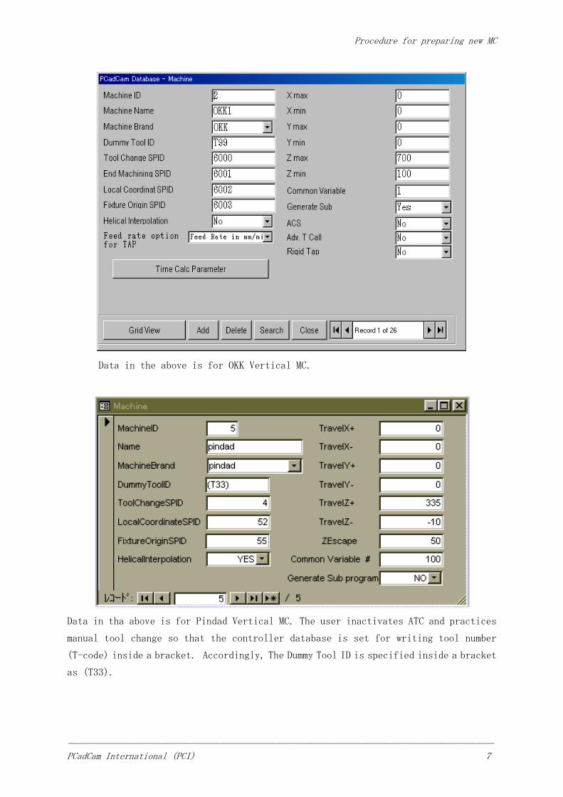
Data in the above is for OKK Vertical MC.
Data in tha above is for Pindad Vertical MC. The user inactivates ATC and practices
manual tool change so that the controller database is set for writing tool number
(T-code) inside a bracket. Accordingly, The Dummy Tool ID is specified inside a bracket
as (T33).

Procedure for preparing new MC
――――――――――――――――――――――――――――――――――――――――――――― PCadCam International (PCI) 8
Data in the above is for a Vertical NC Milling Machine on which user practices manual
tool change. NC controller of the machine is so set to neglect all T-codes written in
NC program. Therefore, Dummy Tool ID does not have to be placed in a bracket. It is
therefore specified simply as T999.

Procedure for preparing new MC
――――――――――――――――――――――――――――――――――――――――――――― PCadCam International (PCI) 9
Data in the above is for a Vertical MC attached with A-axis index devise.
Data in the above is for a Horizontal MC attached with A-axis index devise.

Procedure for preparing new MC
――――――――――――――――――――――――――――――――――――――――――――― PCadCam International (PCI) 10
5.1.3. Tool Pod Database
Tool Pod Database lists up all tools that may be used on a machine for each individual
machine (not machine brand).
Frequency value in the right most column indicates number of times when the tool has
been selected by the CAM system. The number is counted up every time the tool is selected.
When two or more candidate tools are found for an operation, CAM system looks up this
column and selects the tool having the largest number, reflecting the past history that
the tool has been used more frequently than other candidate tools.
Using this capability, if user manually assigns a large value in this column, the
tool has less chance to be removed from the tool pod data. Therefore, the tool is
eventually managed as the permanent resident tool of the machine.

Procedure for preparing new MC
――――――――――――――――――――――――――――――――――――――――――――― PCadCam International (PCI) 11
5.1.4. Controller Database
The database assigned with Controller ID “1” holds a set of data for FANUC controller.
Do not delete this dataset because it is necessary for automatic data management inside
the software.
Data in the above is an example for Yasnuc controller.
Tool offset values both for tool length and diameter are not written in the NC program
for this machine, but manually set by the operator to the machine controller as H- and
D-codes. Therefore, in order to cancel data transfer capability of NC program, G10
Length, G10 Diameter and G10 Value lines are all nullified by entering “\n”.
“\” mark in the example data above is a replacement for backslash “\”.

Procedure for preparing new MC
――――――――――――――――――――――――――――――――――――――――――――― PCadCam International (PCI) 12
Data in the above is for OSP controller (Okuma). The machine does not have a command
to specify Metric/Inch, therefore the format is nullified by entering “\n”.
Data in the above is for Meldas controller.
Procedure for preparing new MC
――――――――――――――――――――――――――――――――――――――――――――― PCadCam International (PCI) 13
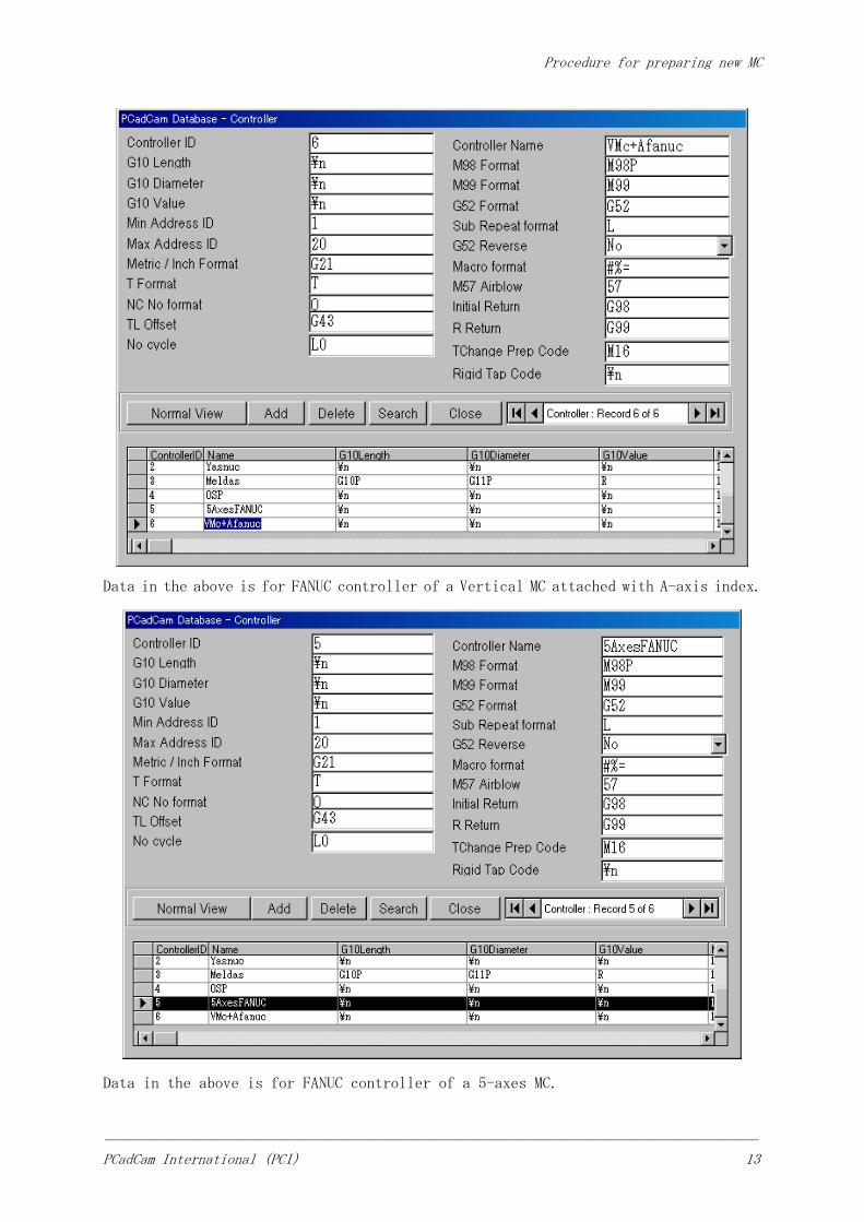
Data in the above is for FANUC controller of a Vertical MC attached with A-axis index.
Data in the above is for FANUC controller of a 5-axes MC.

Procedure for preparing new MC
――――――――――――――――――――――――――――――――――――――――――――― PCadCam International (PCI) 14
5.1.5. Index Table Database
(Horizontal MC, Vertical MC with Index, and 5-Axes Machining)
Index Table Bata base is necessary for rotational index of A-, B- or C-Axis angle.
Three data items have to be prepared for each of A, B and C angle endexing.
Index Table Data base below is for a Horizontal MC that has only B-axis. Therefore
three data are entered only for B.
(1) Index Address is a text form data in which the angle of table index is substituted
by “%”. In the example shown in the above which is for Okuma Horizontal MC, the text
form reads “VC110=%” so that, if angle value is 90 degree, NC program will be written
“VC110=90”.
(2) Index Sub-Program number is the sub-program number of the machine resident
sub-program that rotates B-axis. The sub-program number is 6010 in the example above.
(3) Min Angle of Rotation is the unit angle value that corresponds to value “1” of
the angle entered in (1) in the above. It is usually set to be 1.

Procedure for preparing new MC
――――――――――――――――――――――――――――――――――――――――――――― PCadCam International (PCI) 15
Data in the above is for a Vertical MC attached with A-axis index devise.
Data in the above is for a five-axes Vertical MC attached with B-axis rotary index
carried on A-axis indexing tranion.

Procedure for preparing new MC
――――――――――――――――――――――――――――――――――――――――――――― PCadCam International (PCI) 16
5.2. Machine Resident Sub-Program Preparation
5.2.1. Tool Change Sub-Program
Enshu 400 OKK Okuma
% % %
O6000 L6000 O6000
G21 G91 G00 G28 G40 G80
G52 X0.Y0.Z0. M6
G54 G92 G53XYZ0. RTS
G40 G80 M06 %
G91 G30 G23
Z0. %
G28 Y0.
G28 X0.
G28 Z0.
M6
M99
%
YASNUC Controller MELDAS Controller OSP Controller
Pindad(manual tool change)
MAKINO(CNC vertical milling
machine)
% %
O0004 O0004
G21 G54 G40 G49 G80 G40 G80 G49 G90 G17
G52 X0.Y0. Z0. G52 X0.Y0. Z0.
G91 G30 Z0. M98 P55
G91 Z-5. M00
G90 G00 M99
G55 X0.Y0. %
M00
20.X300.
G91 G30 Z0.
M99
%
FANUC Controller FANUC Controller
In the case of three machines in the upper table, since the Tool Change sub-program
number has been set to be 6000 in the Machine Database, Tool Change sub-program starts
with sub-program number O6000 (L6000 for MELDAS controller).
O4000 in the case of two machines listed in the lower table,
First line after the sub-program number lists a code for canceling Local Coordinate
Shift. G52 for Enshu400machine, G92G53XYZ0. for OKK machine and G52X0.Y0.Z0. for

Procedure for preparing new MC
――――――――――――――――――――――――――――――――――――――――――――― PCadCam International (PCI) 17
Pindad and MAKINO machines.
Subsequently, the spindle is moved to a position appropriate for the tool change
motion, then Tool Change code M6 is listed. In the case of Pindad and MAKINO machines
which are for manual tool change, M06 is replaced with a machine stop code M00
5.2.2. Ending Operation Sub-Program
Enshu Vertical MC
%
O6001
M9
G91 G30 Z0.
M5
M99
%
YASNUC Controller
5.2.3. Fixture Origin Point (FXO) Sub-Program
Fixture Origin point (FXO) sub-program is necessary if Automatic Coordinate System
(ACS) calculation is set activated in the Machine Data base. It is not necessary if
Work Piece Reference Point is measured on the machine and manually input to the machine
controller.
Okuma Horizontal MC Horizontal MC Enshu Vertical MC
% % %
O6003 O6003 O6003
VC111=VZOFX[55] G40 G80 G17 G40 G49 G80 G90 G17 G52
VC112=VZOFY[55] #111= #5241 G91 G30 Z0.
VC113=VZOFZ[55] #112= #5242
#113= #5243
G55
#111= #5241
#112= #5242
#113= #5243
RTS M99 Y0.
% % M99
%
OS Controller FANUC Controller YASNUC Controller
FXO sub-program number for those machines have been set to be 6003 in Machine database,
sub-program number is written O6003 in examples in the above. First line after the
Procedure for preparing new MC
――――――――――――――――――――――――――――――――――――――――――――― PCadCam International (PCI) 18
sub-program number lists a number of cancel codes including Local Coordinate Shift
cancel. Examples in the above are for machines whose Local Coordinate Format has been
set G56 in the controller database.
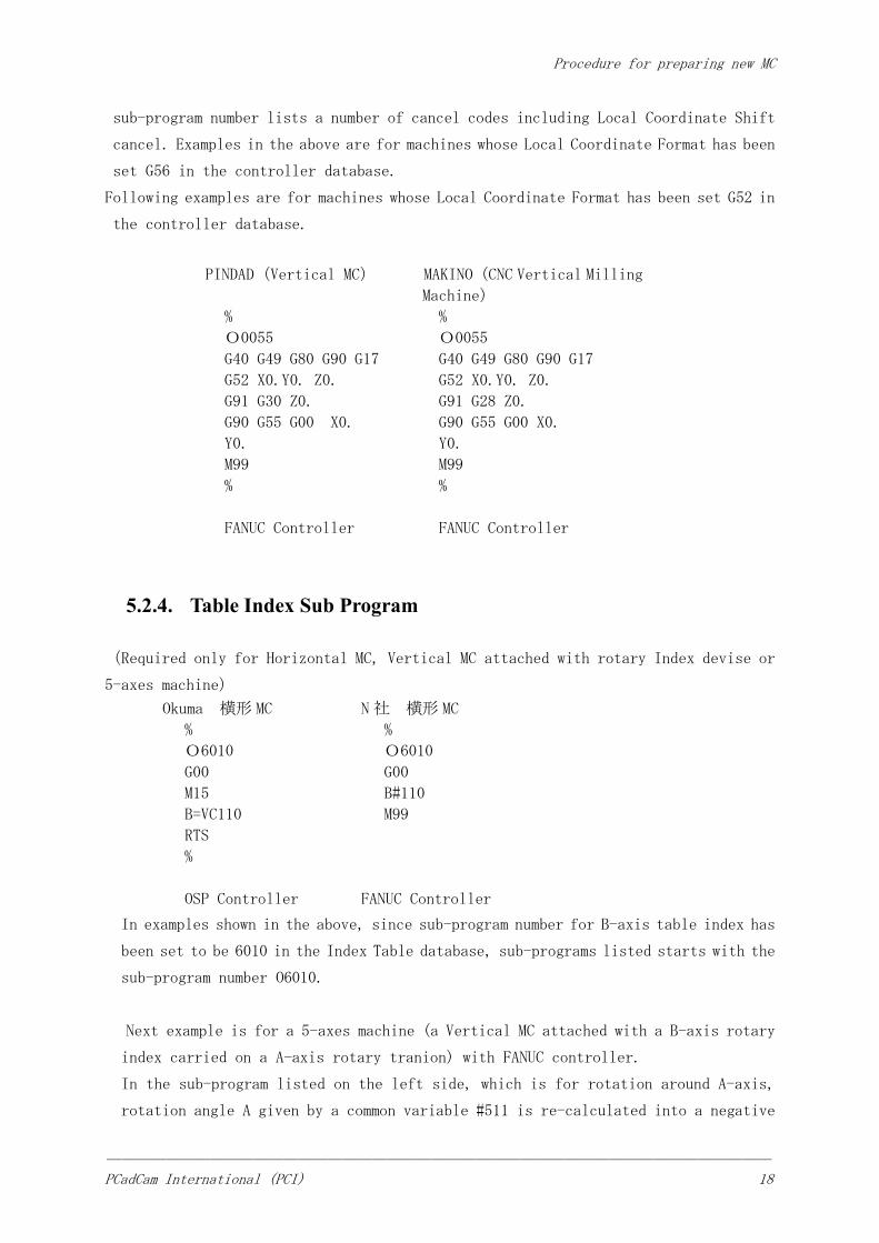
Following examples are for machines whose Local Coordinate Format has been set G52 in
the controller database.
PINDAD(Vertical MC) MAKINO(CNC Vertical Milling
Machine)
% %
O0055 O0055
G40 G49 G80 G90 G17 G40 G49 G80 G90 G17
G52 X0.Y0. Z0. G52 X0.Y0. Z0.
G91 G30 Z0. G91 G28 Z0.
G90 G55 G00 X0. G90 G55 G00 X0.
Y0. Y0.
M99 M99
% %
FANUC Controller FANUC Controller
5.2.4. Table Index Sub Program
(Required only for Horizontal MC, Vertical MC attached with rotary Index devise or
5-axes machine)
Okuma 横形 MC
%
O6010
G00
M15
B=VC110
RTS
%
N 社 横形 MC
%
O6010
G00
B#110
M99
OSP Controller
FANUC Controller
In examples shown in the above, since sub-program number for B-axis table index has
been set to be 6010 in the Index Table database, sub-programs listed starts with the
sub-program number O6010.
Next example is for a 5-axes machine (a Vertical MC attached with a B-axis rotary
index carried on a A-axis rotary tranion) with FANUC controller.
In the sub-program listed on the left side, which is for rotation around A-axis,
rotation angle A given by a common variable #511 is re-calculated into a negative

Procedure for preparing new MC
――――――――――――――――――――――――――――――――――――――――――――― PCadCam International (PCI) 19
value by subtracting 360 degree if the given value is greater than 180 degree.
[A-axis rotation
sub-program]
%
O6011
IF[#511LE180]GOTO 100
#511=#511-360
N100 G00
A#511
M99
%
[B-axis rotation
sub-program]
%
O6012
G00
B#512
M99
%
5.3. Setting of Fixture Origin Point Coordinate
Fixture Origin point (FXO) is set in the Work Piece Coordinate (usually G55) of the
machine controller if Automatic Coordinate System (ACS) calculation is set activated
in the Machine Data base. It is not necessary if Work Piece Reference Point is measured
on the machine and manually input to the machine controller.
5.3.1. Vertical MC
[Example for Enshu Vertical MC]
As G55 is used in the Fixture Origin (FXO) sub-program, G55 Work Piece Coordinate of
the machine controller is set as follows:
G55
X=
Y=
Z=
XYZ values are the machine coordinate of the Fixture Origin (FXO) of the fixture asit
is mounted on the machine table.
5.3.2. Horizontal MC
Fixture Origin (FXO) point of a Horizontal MC has to be set on the axis of table rotation.
[Example for Okuma Horizontal MC]

Procedure for preparing new MC
――――――――――――――――――――――――――――――――――――――――――――― PCadCam International (PCI) 20
As VZOF[55] is used in the Fixture Origin (FXO) sub-program, G55 Work Piece Coordinate
of the machine controller is set as follows:
G55
X=0
Y=
Z=-200
Y is the height of FXO as measured in the machine coordinate.
Z=-200 is so set because the Z machine coordinate of the center of table rotation of
the machine is at Z=-200.
5.3.3. 5-axes MC
Fixture Origin (FXO) point of a 5-axes MC has to be set at the intersection of two axes of rotational
motions: namely, at the intersection of either A- and B-, A- and C- or B- and C-axis of rotation.
G55
X=
Y=
Z=
XYZ values are the machine coordinate of the Fixture Origin (FXO) as it is described
in the above.