v1 · a user can use multiple referee systems to form a multi-robot combat system. the referee...
TRANSCRIPT

Prepared by the RoboMaster Organizing Committee March, 2019
V1.2
REFEREE SYSTEM
USER MANUALUpdated on February, 2020
2 © 2020 DJI All Rights Reserved.
DisclaimerPlease read this disclaimer carefully before using this product. By using this product, you hereby signify that you have read and agreed to all content herein. Please install and use this product properly and in strict accordance with the User Manual and product instructions, as well as any relevant laws, regulations, and policies. Users shall be responsible for the consequences resulting from their behavior while using this product. DJI™ Innovations (DJITM) shall not be liable for any losses incurred from using, installing, or modifying this product improperly. DJITM and RoboMasterTM are trademarks of SZ DJI Technology Co., Ltd and its affiliates. Names of products, brands, etc. herein are trademarks or registered trademarks of their respective owner companies. This product, the manual, and the software and driver that work with the Referee System (RoboMaster Client, RoboMaster Server, RoboMaster Tool 2, and DJI WIN driver) are copyrighted by DJI with all rights reserved, and shall not be modified, reproduced, or transmitted in any form without the prior consent of DJI. DJI reserves the right of final interpretation of this disclaimer.
WarningsRead the ENTIRE user manual to become familiar with the features of this product before operating. Failure to operate the product correctly can result in damage to the product or personal property and cause serious injury. This is a sophisticated product. It must be operated with caution and common sense and requires some basic mechanical ability. Taking into account the importance of the various modules of the Referee System in the competition, the Referee System has been fully tested in the factory and each module cannot be damaged easily. A user should not disassemble or modify any parts of the Referee System without authorization. Damage to the Referee System resulting from unauthorized disassembly will void the warranty. This product is not intended for use by children without direct adult supervision. DO NOT use with incompatible components or alter this product in any way outside of the documents provided by RoboMaster. Install and use this product in strict accordance with the guidelines provided by RoboMaster. It is essential to read and follow all of the instructions and warnings in the user manual, prior to assembly, setup or use.
Product Usage Precautions1. Please ensure that the robot side of the Referee System is installed correctly and firmly before use.2. Please ensure that the wiring connection between each module on the Referee System’s robot side is
correct before use.3. Please ensure that the components are intact before use. Replace any worn or damaged components.
Using This ManualLegend
Important Hints and Tips Reference
Related Documents
1. Specification of Each Referee System ModuleIt is recommended to read the aforementioned documents to understand the features and installation methods of each Referee System module. Reserve any necessary installation holes and spaces so that each module on the Referee System's Robot Side may be correctly installed, and then read the User Manual to explore the features of the Referee System.
Release Notes
Date Version Revision RecordJan. 2019 v1.0 First ReleaseMar. 2019 v1.1 Added VT02 & VT12 Video Transmitter Modules and Instructions
Jan. 2020 v1.2 Main Controller function to synchronously edit and delete VT01 & VT11 Video Transmitter Modules

© 2020 DJI All Rights Reserved. 3
Contents
Disclaimer 2
Warning 2
Product Usage Precautions 2
Using This Manual 2
Symbol Descriptions 2
Related Documents 2
Referee System Overview 5
Client and Server Overview 9
Client 9
Server 9
Referee System Quick Start Guide 10
Robot Side Configuration 10
Robot Property Descriptions 10
Competition Configuration 11
1v1 Mode 11
3v3 Mode 12
Description of Robot Side Functions 13
Robot Side Interaction Instructions 13
Homepage UI Description 13
Homepage 13
Real-time Information Page 14
Descriptions of Key Functions 14
Function Page 14
UI Function Descriptions 15
Rule Parameter Settings 18
Wi-Fi Settings 19
Reading Module Versions 20
Debug Function 21
Introduction to the Robot Side Module Initialization 21
4 © 2020 DJI All Rights Reserved.
Video Transmitter Module (VT02 & VT12) Instructions 21
Activation of the VTM Transmitter 21
Activation of the VTM Receiver 22
VTM Channel Configuration 23
RoboMaster Referee System User Interface Guide 27
Checking Functions on the Robot Side 27
RoboMaster Tool 2 Upgrade Procedure 28
Introduction to the Main Upgrade Interface 28
Upgrade Procedure 29
RoboMaster Server 31
Server Configuration 31
RoboMaster Client 31
Client Configuration 32
Setting up a LAN 32

© 2020 DJI All Rights Reserved. 5
Referee System OverviewThe Referee System is a fully automated electronic penalty system with features that can detect projectile attacks, display the robot's current HP and status, and monitor chassis movement power. The Speed Monitor Module monitors the robot's initial firing speed and launch speed; the Video Transmitter Module provides the user with a first-person view of the robot; the RFID Interaction Module interacts with the battlefield; and the Positioning System Module provides information on the robot's battlefield location. A user can use multiple Referee Systems to form a multi-robot combat system.
The Referee System is composed of the following:1. The robot side of the Referee System (hereinafter referred to as "Robot Side")2. The PC client (hereinafter referred to as "Client") and the PC server (hereinafter referred to as "Server")
Robot Side Modules
1) Main Controller Module (MC02): The Main Controller Module is the core control unit of the Referee System that monitors the operation of the entire system and includes human-machine interaction, wireless communication and status display features.
Power Management Module (PM02)
2) Power Management Module (PM02): The Power Management Module functions control power to the chassis, gimbal, and launching mechanism, transmit data, detect the chassis power consumption, and automatically cut off power supply for propulsion when a robot's HP drops to zero.
Main Controller Module (MC02)

6 © 2020 DJI All Rights Reserved.
Light Indicator
Module (LI01)
3) Light Indicator Module (LI01): The Light Indicator Module shows the current HP and status of your robot. By observing the status of the light indicator, you can identify the remaining HP and status of your robot.
4) Armor Modules (AM02 & AM12): The Armor Modules detect the status of incoming projectile attacks and collisions. They are divided into the Small Armor Module and the Large Armor Module.
5) Speed Monitor Modules (SM01 & SM11): The Speed Monitor Modules detect the robot's initial firing speed and launch speed. This includes one Speed Monitor Module for 17mm projectiles and one for 42mm projectiles.
Armor Module Support
Frame A (AH02)
Small Armor Module
(AM02)
Large Armor
Module (AM12)
Speed Monitor Module for
17mm projectiles (SM01)
Speed Monitor Module for
42mm projectiles (SM11)
6) RFID Interaction Module (FI02): This module enables the Robot Side to interact with the battlefield.
RFID Interaction Module (FI02) RFID Interaction Module test card
© 2020 DJI All Rights Reserved. 7
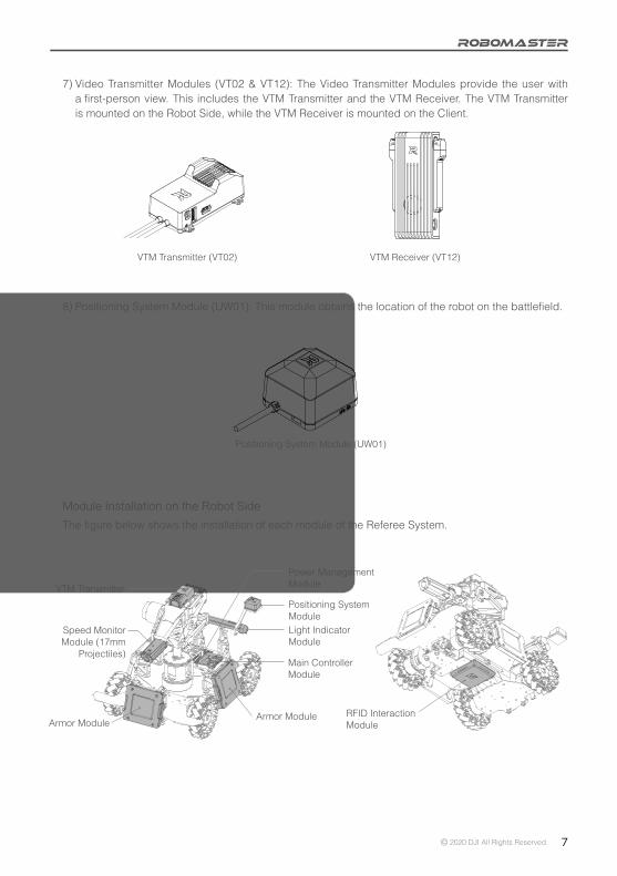
7) Video Transmitter Modules (VT02 & VT12): The Video Transmitter Modules provide the user with a first-person view. This includes the VTM Transmitter and the VTM Receiver. The VTM Transmitter is mounted on the Robot Side, while the VTM Receiver is mounted on the Client.
8) Positioning System Module (UW01): This module obtains the location of the robot on the battlefield.
VTM Transmitter (VT02) VTM Receiver (VT12)
Positioning System Module (UW01)
Module Installation on the Robot Side
The figure below shows the installation of each module of the Referee System.
RFID Interaction Module
Positioning System Module
Power Management Module
Light Indicator Module
Main Controller Module
VTM Transmitter
Speed Monitor Module (17mm
Projectiles)
Armor ModuleArmor Module

8 © 2020 DJI All Rights Reserved.
Module Connection Diagram on the Robot Side
The figure below shows the connection of each module of the Referee System.
* Module installation and use may vary for different robots. Please refer to the RoboMaster 2020 Robot Building
Specification Manual.
Download: https://www.robomaster.com/en-US/resource/download

© 2020 DJI All Rights Reserved. 9
Client and Server OverviewClient
The Client is a First-person View (FPV) operation application for the player. After connecting to the self-built server or competition server, you can check the robot-related data uploaded by the Referee System on the Client, including current HP, real-time projectile initial firing rate, firing rate, mini-map of the battlefield, real-time chassis power output, teammate information, etc.
To implement the features mentioned above, the following hardware and software should be installed on the Client.
1. Client hardware configuration
a. VTM Receiver (outputs a video signal)b. Robot remote controller (user-supplied; only DT7 & DR16 remote controller receiver systems are
supported)
2. Client software configuration
a. DJI WIN driver (drives the robot remote controller)Download:
https://www.robomaster.com/en-US/products/components/detail/1837
b. RoboMaster Client softwareDownload:https://www.robomaster.com/en-US/products/components/referee
Server
The Server is the control center of the whole Referee System. It collects data from all robots, competition battlefield institutions, and Clients during the competition, presents them to the referees in a visualized way, and automatically handles the identification logic to determine the outcome of the competition. The following software should be installed on the Server to implement the features above.
RoboMaster Server softwareDownload:https://www.robomaster.com/en-US/products/components/referee

10 © 2020 DJI All Rights Reserved.
Referee System Quick Start GuideRobot Side Configuration
Different types of robot can be set up on the Robot Side through the Main Controller Module. At the same time, the type and quantity of robot Referee System Modules can also be customized on the Server. The table below shows the configuration of a single robot Referee System module. (The type and number of modules required depend on the robot type. For installation details, please refer to the RoboMaster 2020 Robot Building Specification Manual).
Module Name Quantity
Main Controller Module 1
Power Management Module 1
Light Indicator Module 0-1
Large and Small Armor Modules 0-6
Speed Monitor Module (17mm Projectiles) 0-4
Speed Monitor Module (42mm Projectiles) 0-1
RFID Interaction Module 0-1
VTM Transmitter 0-1
VTM Receiver 0-1
Robot Property Descriptions
The properties of different types of robots can be configured on the Server and synchronized to the Robot Side.
The table below shows the properties that can be configured:
Property Name Property Information
Referee System module type and quantity Refer to the "Robot Side Configuration" section
Initial HP 0-65535
Maximum HP The maximum HP if the robot's level can be upgraded in competition: Initial HP - 65535
Damage from 17mm projectiles HP deducted when the Armor Module receives attacks from 17mm projectiles: 0-Initial HP
Damage from 42mm projectiles HP deducted when the Armor Module receives attacks from 42mm projectiles: 0-Initial HP
17mm projectile launch speed limit HP will be deducted from the robot when it exceeds this limit
42mm projectile launch speed limit HP will be deducted from the robot when it exceeds this limit
Robot's barrel heat limit HP will be deducted from the robot when it exceeds this limit
Robot's critical modules offline HP will be deducted from the robot when critical modules are offline
Robot chassis power consumption limit HP will be deducted from the robot when it exceeds this limit and its energy level

© 2020 DJI All Rights Reserved. 11
Competition Configuration
Multiple Referee Systems can be combined to form a multi-robot combat mode. Users can choose to set up a local area network (LAN) for online combat based on their current status and conditions.If a local area network (LAN) is set up, the Server must be used, and users can be able to check the HP and Referee System status of all Robot Sides on the Server. Users may also use the Client, paired with the VTM Receiver, to operate a robot from a first-person view, check the HP and status of all Robot Sides, and determine the outcome of the competition automatically with the aid of the Server.
If a LAN is not being used, a server is not required, but the outcome of the competition can only be determined by the HP displayed on the Light Indicator Module of the Referee System. Additionally, users may use the Client paired with the VTM Receiver to operate a robot from a first-person view, but cannot check HPs on the Robot Side nor determine the outcome of the competition automatically.
Users may also opt to use base or customize competition rules for a more personalized experience. The following examples cover "1v1 Mode" and "3v3 Mode".
1v1 ModeUsers can select any two Robot Side configurations from the configuration table to be applied to two robots respectively. One robot will be assigned to the Red team, and the other to the Blue team. You can choose whether to set up a LAN or use a base for the 1v1 contest.
The table below gives an example of a starting lineup:
Combatants Robot type Quantity Remarks
Red teamStandard 1 /
Base 0-1 Optional
Blue teamStandard 1 /
Base 0-1 Optional
The table below shows the configurations of the Referee System modules required to set up the combat system above:
Module Name Quantity Remarks
Main Controller Module 2 /
Power Management Module 2 /
Light Indicator Module 2 /
Large Armor Module 0 /
Small Armor Module 0-8 /
Speed Monitor Module (17mm Projectiles)
0-2 Can be ignored if the launch speed is unlimited
Speed Monitor Module (42mm Projectiles)
0 /
RFID Interaction Module 0-2 Can be ignored if no interaction with a battlefield is required
VTM Transmitter 2 /
VTM Receiver 2 /

12 © 2020 DJI All Rights Reserved.
3v3 ModeYou may arbitrarily select six sets of Robot Side configurations according to the Robot Side configuration table and install them to six robots respectively. Each set of Robot Sides can be set as Red Team or Blue team. Make sure that three of them are set as Red team and the rest of them as Blue Team. The Robot Side can choose whether to set up a LAN or use a base for the 3v3 contest.
The table below gives an example of a starting lineup:
Combatants Robot type Quantity Remarks
Red team
Standard 1 /
Hero 1 /
Engineer 1 /
Base 0-1 Optional
Blue team
Standard 1 /
Hero 1 /
Engineer 1 /
Base 0-1 Optional
The table below shows the configurations of the Referee System modules required to set up the 3v3 combat system above:
Module Name Quantity Remarks
Main Controller Module 6 /
Power Management Module 6 /
Light Indicator Module 6 /
Large Armor Module 0-8 /
Small Armor Module 0-16 /
Speed Monitor Module (17mm Projectiles)
0-4 Can be ignored if the launch speed is unlimited
Speed Monitor Module (42mm Projectiles)
0-2 Can be ignored if the launch speed is unlimited
RFID Interaction Module 0-6Can be ignored if no interaction with a battlefield is required
VTM Transmitter 6 /
VTM Receiver 6 /

© 2020 DJI All Rights Reserved. 13
Description of Robot Side FunctionsRobot Side Interaction Instructions
The human-computer interaction interface of the Referee System consists of a display screen and four keys. As shown in the figure below, pressing a key will enable the corresponding function. Pressing and holding the same key will enable a different function.
Homepage UI Description
HomepageThis interactive webpage displays the initialization status of the Referee System. When the initialization is complete, the RoboMaster logo is displayed, as shown in the figure below:
Or the quantity and names of the offline modules are displayed, as shown in the figure below:
1. The " " in the upper left corner indicates that the Robot Side is not connected to the Server.2. The " " in the upper right corner indicates the Wi-Fi connection status and signal strength.3. The " " in the upper right corner indicates the current Wi-Fi connection type. The significance of the
pattern descriptions is as follows:a) : The currently connected Wi-Fi is the User AP. A solid line means it is connected, and a dotted
line means it is connecting.b) : The currently connected Wi-Fi is the Inspection AP. A solid line means it is connected, and
a dotted line means it is connecting.c) : The currently connected Wi-Fi is the Competition AP. A solid line means it is connected, and
a dotted line means it is connecting.
PgUp
Display
OK
PgDnCancel
Main Controller panel diagram
11 MODULESFAULT
LightInd Offline

14 © 2020 DJI All Rights Reserved.
11 MODULESFAULT
LightInd Offline
Robot ID
Robot Type
Module
Game
Wi-Fi
Setup
Setup
Setup
Setup
Setup
Set Robot ID
Set Robot Type
Module Settings
Rule Parameter Settings
Wi-Fi settings
Press and hold the OK key
11 MODULESFAULT
LightInd Offline
Press the OK key
Press the PgDn key
Robot Type/ID
Real-time heat of a 17mm projectile/maximum heat
Real-time launch frequency of 17mm projectiles
Real-time HP/Total HP
Hero
17mmSpeed:
17mmHeat:
17mmFreq:
HP: 300/300
Red 1
0.0/
0.0/
0.0
30
240
Real-time robot coordinates
Real-time heat of a 42mm projectile/maximum heat
Real-time launch frequency of 42mm projectiles
Last digit of the Main Controller version number
Real-time Information PageThe real-time information page displays the real-time parameters of a robot, such as robot chassis power.The real-time information page is shown below:
4. "11 MODULES FAULT" in the center means 11 modules are currently offline or defective.5. "LightInd Offline" at the bottom means that the current Light Indicator Module is offline.6. " " in the bottom left corner means that there is more than one defective module. By pressing the up or
down keys, you can see the error information for the current offline or defective modules.
Descriptions of Key Functions• Press and hold the OK key: On the homepage or real-time information display page, press and hold
the OK key to enter the robot function page. For some function pages, the current settings can be saved.
• Press the OK key: On the homepage, press the OK key to enter the real-time information display page. On the function page, if there is a page link in the selected line on the current page, pressing the OK key will direct you to the linked page; otherwise, pressing the OK key will select a function.
• Press and hold the Cancel key: On a page other than the homepage, pressing and holding the Cancel key will bring you back to the homepage. On the homepage, pressing and holding the Cancel key will refresh the screen display.
• Press the Cancel key: Return to the previous page.• Press or press and hold the PgUp key: On the function page, press the PgUp key to move up one line.
On other pages, press the PgUp key to move up one page.• Press or press and hold the PgDn key: On the function page, press the PgDn key to move down one
line. On other pages, press the PgDn key to move down one page.• On a page other than the homepage, if no keys are pressed during a 30-second period, you will be
automatically directed to the homepage.
Function PageThe function page is used to display and set the robot functions, such as setting the Robot ID.The function page is shown below:
Current transmission channel/pre-set channel
Pos(0.0,0.0,0)
42mmSpeed:
42mmHeat:
42mmFreq:
Camera: 0/0 Ver: 0.0
0.0/
0.0/
0.0
16
200
Real-time launch speed of a 42mm projectile/maximum launch speed
Real-time launch speed of a 17mm projectile/maximum launch speed

© 2020 DJI All Rights Reserved. 15
Robot Type/ID
Real-time heat of a 17mm projectile/maximum heat
Real-time launch frequency of 17mm projectiles
Real-time HP/Total HP
Real-time robot coordinates
Real-time heat of a 42mm projectile/maximum heat
Real-time launch frequency of 42mm projectiles
Last digit of the Main Controller version number
Press the PgDn key
Real-time power/Maximum power
Current buff increase
Wi-Fi connection status
Server connection status
PowerBuf
Power
BUFF: No Buff
Customer AP Connected
Can't find server
0.0/
0.0
60
80
UI Function Descriptions
This chapter explains the actual use of the Main Controller UI, which includes functions such as the Robot ID settings, robot type settings, module settings, rule parameter settings, and Wi-Fi settings.
Set Robot IDE.g. Set Robot ID to Red 1 Hero:
11 MODULESFAULT
LightInd Offline
Press and hold the OK key
Press the OK key
Press the OK key
Press the OK key
RED
BLUERED 1
RED 2
RED 3
RED 4
RED 5
Hero
Engineer
Standard
Standard
Standard
Robot ID
Robot Type
Module
Game
Wi-Fi
Setup
Setup
Setup
Setup
Setup
Set Robot TypeE.g. Set Robot Type to Standard:
Robot ID
Robot Type
Module
Game
Wi-Fi
Setup
Setup
Setup
Setup
Setup
Robot
Robot
Robot
Robot
Robot
Standard
Hero
Engineer
Sentry
Aerial
11 MODULESFAULT
LightInd Offline
Press and hold the OK key
Press the OK key
Real-time power buff energy level/Maximum power buff energy level

16 © 2020 DJI All Rights Reserved.
Module SettingsSet Armor Module IDThe Robot Side can have several Armor Modules, but they must have the correct ID settings. The Robot Side can identify the direction in which the robot is being attacked based on the Armor Module ID.
The steps to configure the Armor Module ID are as follows:
a. On the function page of the Main Controller Module, proceed as shown to enter the Armor ID Setup page:
b. On this page, select "Armor ID Reset" to enter the Armor ID reset status. The panel light will flash at a certain frequency (for a red robot, the red light flashes; for a blue robot, the blue light flashes).
c. Strike each Armor Module in succession with a consistent amount of force. If the armor light goes off and then comes back on, the Armor ID has been set successfully. The ID of the Armor Module that is hit first is 0, and the ID is sequentially incremented according to the order in which the modules are struck.
d. After completing the above operations, check whether the armor ID has been set successfully by looking up the version number of the Armor Modules. If the read number of effective Armor Modules is the same as the number of Armor Modules installed, the procedure is complete.
Be sure to set the ID of an Armor Module before use and ensure that the IDs of Armor Modules connected to the same Main Controller Module are not repeated. If there is a configuration error, the Robot Side self-test will detect that the Armor Module is offline.
Set Speed Monitor Module ID
The Robot Side can have several Speed Monitor Modules, but they must have the correct ID settings. The Robot Side can distinguish between the detected projectile information and the module's own angle information based on the Speed Monitor Module ID.
The steps to configure the Speed Monitor Module ID are as follows: a. On the function page of the Main Controller Module, proceed as shown to enter the Speed Monitor
ID Setup page:
Armor ID Reset
Speed Mon ID Reset
Compass Calibration11 MODULESFAULT
LightInd Offline
Press and hold the OK key
Press the OK key
Robot ID
Robot Type
Module
Game
Wi-Fi
Setup
Setup
Setup
Setup
Setup
Armor ID Reset
Speed Mon ID Reset
Compass Calibration11 MODULESFAULT
LightInd Offline
Press and hold the OK key
Press the OK key
Robot ID
Robot Type
Module
Game
Wi-Fi
Setup
Setup
Setup
Setup
Setup

© 2020 DJI All Rights Reserved. 17
Armor ID Reset
Speed Mon ID Reset
Compass Calibration11 MODULESFAULT
LightInd Offline
Press and hold the OK key
Press the OK key
Robot ID
Robot Type
Module
Game
Wi-Fi
Setup
Setup
Setup
Setup
Setup
b. On this page, select "Speed Mon ID Reset" to enter the Speed Monitor Module ID reset status. The side light panel of the Speed Monitor Module will flash red and blue at a set frequency.
c. In sequential order, insert an opaque object into the barrel of the Speed Monitor Module to trigger the infrared sensor on the front end of the module. The side light panel will flash yellow, then go out and restart. Configuration of the Speed Monitor Module ID is now complete. The ID of the first 17mm-projectile Speed Monitor Module triggered is set to 0, and for each 17mm-projectile Speed Monitor Module triggered after that, this goes up in increments of 2: 2, 4, 6, etc. The ID of the first 42mm-projectile Speed Monitor Module triggered is set to 1, and for each 42mm-projectile Speed Monitor Module triggered after that, this goes up in increments of 2: 3, 5, 7, etc.
d. After completing the above operations, check whether the Speed Monitor ID has been set successfully by looking up the version number of the Speed Monitor Module. If the read number of effective Speed Monitor Modules is the same as the number of Speed Monitor Modules installed, the Speed Monitor Module ID configuration is complete.
Speed Monitor Module Compass Calibration
The compass on the Speed Monitor Module can be calibrated through the interactive interface. This provides data for the Robot Side and the Server to help determine the robots destroyed.The steps to calibrate the Speed Monitor Module are as follows:
a. On the function page of the Main Controller Module, proceed as shown to enter the Speed Monitor Module Calibration Setup page.
b. On this page, select "Compass Calibration" to enter the Speed Monitor Module calibration status. The side light panel of the Speed Monitor Module will show a row of green lights, which is the horizontal calibration progress bar.
c. Keep the barrel of the Speed Monitor Module horizontal (the angle of the Pitch and Roll axes should be less than 10°), and on the same spot, rotate 360° along the Yaw axis of the Speed Monitor Module. The horizontal calibration progress bar indicated by the side light panel of the Speed Monitor Module will gradually fill until the horizontal calibration is complete.
d. When the horizontal calibration is complete, the side light panel of the Speed Monitor Module will show a row of purple lights, which is the vertical calibration progress bar.
e. Keep the barrel of the Speed Monitor Module in the positive or negative direction of gravity (the angle difference should be less than 10°), and on the same spot, rotate 360° along the Roll axis of the Speed Monitor Module. The vertical calibration progress bar indicated by the side light panel of the Speed Monitor Module will gradually fill until the vertical calibration is complete.
f. If the calibration is unsuccessful, please repeat the above steps, or refer to the Speed Monitor Module installation guidelines in the RoboMaster 2020 Robot Building Specification Manual to check whether the Speed Monitor Module has been installed correctly.

18 © 2020 DJI All Rights Reserved.
11 MODULESFAULT
LightInd Offline
Press and hold the OK key
Press the OK key
Robot ID
Robot Type
Module
Game
Wi-Fi
Setup
Setup
Setup
Setup
Setup
Rule Parameter SettingsIn offline status, through the interactive interface, you can set the robot's maximum HP, the maximum projectile initial firing speed, and the barrel heat limit.For example, you can set the robot's power limit to infinite:
Press the PgDn key2 times
Press the OK key
Reset
MaxHP
MaxPower
MaxSpeed0
MaxSpeed1
HP
Setup
Setup
Setup
Setup
Reset HP
Set max. HP
Set max. power
Reset
MaxHP
MaxPower
MaxSpeed0
MaxSpeed1
HP
Setup
Setup
Setup
Setup
Set MaxPower Success
Press the PgDn key2 times
Press the OK key
MaxPower: 80
MaxPower: 120
MaxPower: Unlimited
MaxPower: 80
MaxPower: 120
MaxPower: Unlimited
Based on the procedures above, you can also configure the following functions:1. Reset HP2. Set max. HP3. Set max. power4. Set max. launch speed of a 17mm projectile5. Set max. launch speed of a 42mm projectile6. Set max. heat of a 17mm projectile7. Set max. heat of a 42mm projectile
Set the max. launch speed of a 17mm projectile
Set the max. launch speed of a 42mm projectile

© 2020 DJI All Rights Reserved. 19
Wi-Fi SettingsWi-Fi Connection
Through the interaction interface, users can choose a pre-set SSID configuration (the Wi-Fi name) on the Robot Side to connect and communicate with the Server, as shown below:
Connecting to:
test0_AP
Connecting to:
test0_AP
Connect Success
test0_AP
test1_AP
test2_AP
test3_AP
test4_AP
Scan SSID
Forget SSID
Connect Information
Select a pre-setconfigured SSIDPress the
OK key
11 MODULESFAULT
LightInd Offline
Press and hold the OK key
Press the OK key
Robot ID
Robot Type
Module
Game
Wi-Fi
Setup
Setup
Setup
Setup
Setup
"SSID" is the Wi-Fi name.After scanning the SSID, select it, and press and hold the OK key to remember it. The Robot Side will automatically connect to this SSID upon startup. Click "Forget SSID" to ignore the remembered SSID.
After connection, the main interface will display the Wi-Fi signal strength, as shown below.
11 MODULESFAULT
LightInd Offline

20 © 2020 DJI All Rights Reserved.
Wi-Fi Information SearchThrough the interaction interface, you can check the Wi-Fi information for the current connection on the Robot Side, as shown below:
Reading Module VersionsThrough the interaction interface, you can check the version number of each module on the Robot Side and check the Armor Module version information, as shown below:
11 MODULESFAULT
LightInd Offline
Press and hold the OK key
Press the OK key
Press the OK key
Robot ID
Robot Type
Module
Game
Wi-Fi
Setup
Setup
Setup
Setup
Setup
Scan SSID
Forget SSID
Connect Information
SSID: test0_AP
Signal: -25dBm
Rssi: 100.00%
Rate: 72Mbit/s
Current Wi-Fi connection name
Signal strength
Signal quality
Sending rate
Module0: 5.0.0.6
Module1: 5.0.0.6
Module2: 5.0.0.6
Module3: 5.0.0.6
Module4: 5.0.0.6
Press the OK key
Press the OK key
Main
Armor
Power
Speed
RFID
Control
Module
Manager
Monitor
Module
11 MODULESFAULT
LightInd Offline
Press and hold the OK key
Module
Game
Wi-Fi
Debug
Read
Setup
Setup
Setup
Option
Version
© 2020 DJI All Rights Reserved. 21
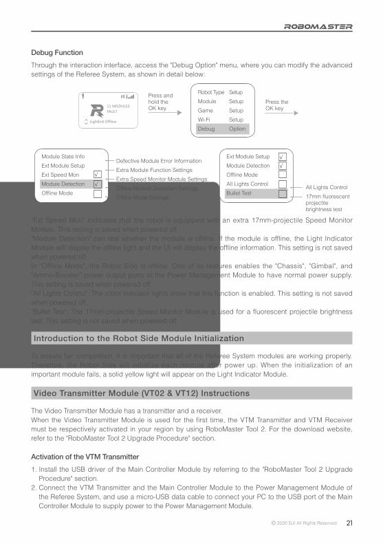
Debug FunctionThrough the interaction interface, access the "Debug Option" menu, where you can modify the advanced settings of the Referee System, as shown in detail below:
11 MODULESFAULT
LightInd Offline
Press and hold the OK key
Press the OK key
Robot Type
Module
Game
Wi-Fi
Debug
Setup
Setup
Setup
Setup
Option
Module State Info
Ext Module Setup
Ext Speed Mon
Module Detection
Offline Mode
√
√
Defective Module Error Information
Extra Module Function Settings
Extra Speed Monitor Module Settings
Offline Module Detection Settings
Offline Mode Settings
Ext Module Setup
Module Detection
Offline Mode
All Lights Control
Bullet Test
√
√
All Lights Control
17mm fluorescent projectile brightness test
"Ext Speed Mon" indicates that the robot is equipped with an extra 17mm-projectile Speed Monitor Module. This setting is saved when powered off."Module Detection" can test whether the module is offline. If the module is offline, the Light Indicator Module will display the offline light and the UI will display the offline information. This setting is not saved when powered off.In "Offline Mode", the Robot Side is offline. One of its features enables the "Chassis", "Gimbal", and "Ammo-Booster" power output ports of the Power Management Module to have normal power supply. This setting is saved when powered off."All Lights Control": The robot indicator lights show that this function is enabled. This setting is not saved when powered off."Bullet Test": The 17mm-projectile Speed Monitor Module is used for a fluorescent projectile brightness test. This setting is not saved when powered off.
Introduction to the Robot Side Module Initialization
To ensure fair competition, it is important that all of the Referee System modules are working properly. Therefore, the Robot Side will initialize each module after power up. When the initialization of an important module fails, a solid yellow light will appear on the Light Indicator Module.
Video Transmitter Module (VT02 & VT12) Instructions
The Video Transmitter Module has a transmitter and a receiver.When the Video Transmitter Module is used for the first time, the VTM Transmitter and VTM Receiver must be respectively activated in your region by using RoboMaster Tool 2. For the download website, refer to the "RoboMaster Tool 2 Upgrade Procedure" section.
Activation of the VTM Transmitter1. Install the USB driver of the Main Controller Module by referring to the "RoboMaster Tool 2 Upgrade
Procedure" section.2. Connect the VTM Transmitter and the Main Controller Module to the Power Management Module of
the Referee System, and use a micro-USB data cable to connect your PC to the USB port of the Main Controller Module to supply power to the Power Management Module.

22 © 2020 DJI All Rights Reserved.
[1] Serial device management area [2] VTM Activation page[3] VTM Transmitter Activation button[4] VTM Receiver Activation button
5. Click the "VTM Activation" page on the left side of the software tool to display the VTM activation interface, where you can click the "VTM Transmitter Activation" button to access the activation procedure. Please re-check your activation region and then click the "Activate" button.
3. Open RoboMaster Tool 2 and check that your PC is properly connected to the Internet.4. On the serial device management area on the left side of the main interface, select a correct serial
device number, then click Open.
6. If activation fails, please check the connection and network status of the VTM, and then repeat the activation operation in step 5.
7. After activation, check whether your activation region matches your mode: Mode 1 for Mainland China and other regions, and Mode 2 for Japan. Once completed, activation cannot be repeated again.
Activation of the VTM Receiver1. Use a USB Type-C data cable to connect your PC to the USB port of the VTM Receiver, and use an
adapter to supply power to the VTM Receiver.2. Open RoboMaster Tool 2 and check that your PC is properly connected to the Internet.3. Install DJI Phantom 4 Drivers_1.2_Installer for the VTM Receiver. Driver download URL: https://www.robomaster.com/en-US/products/components/detail/1497
[3] [4]
[1]
[2]

© 2020 DJI All Rights Reserved. 23
4. Click the "VTM Activation" page on the left side of the software tool to display the VTM activation interface, where you can click the "VTM Receiver Activation" button to display the VTM Receiver Activation window.
5. In the VTM Receiver Activation window, select the corresponding serial port number and click Open. Please re-check your activation region and then click the "Activate" button.
6. If activation fails, please check the connection and network status of the VTM, and then repeat the activation operation in step 5.
7. After activation, check whether your activation region matches your mode: Mode 1 for Mainland China and other regions, and Mode 2 for Japan. Once completed, activation cannot be repeated again.
VTM Channel ConfigurationEach Robot ID is bound with a VTM channel ID. Their correspondence is shown in the table below:
Mainland China and other regions:
Robot ID VTM Channel IDRed 1 1
Red 2 2
Red 3 3
Red 4 4
Red 5 5
Red Aerial (corresponding to the VTM Transmitter ID of the red team's Aerial) 6
Blue 1 6
Blue 2 5
Blue 3 4
Blue 4 3
Blue 5 2
Blue Aerial (corresponding to the VTM Transmitter ID of the blue team's Aerial) 1
[1]
[2]

24 © 2020 DJI All Rights Reserved.
Aerial
USB Type-C interfaceStatus LED
12 V power port
Japan:
Robot ID VTM Channel IDRed 1 20
Red 2 21
Red 3 24
Red 4 25
Red 5 26
Red Aerial (corresponding to the VTM Transmitter ID of the red team's Aerial) 27
Blue 1 22
Blue 2 23
Blue 3 28
Blue 4 27
Blue 5 26
Blue Aerial (corresponding to the VTM Transmitter ID of the blue team's Aerial) 25
The steps to configure the VTM channel are as follows:1. Connect the VTM Transmitter to the Main Controller Module and set the Robot ID. For details,
please refer to the "Set Robot ID" section under "UI Function Descriptions".2. The VTM Receiver ID and video display must be configured through the "RoboMaster Client" on the
PC, as follows:a. Use a USB Type-C data cable to connect your PC to the USB port of the VTM Receiver, and use
a power adapter to power the VTM Receiver. Wait about 20 seconds until the status indicator is solid green, indicating that the Receiver startup is complete.

© 2020 DJI All Rights Reserved. 25
b. Open the Device Manager of your PC and expand the Network Adapter submenu to check for a "Remote NDIS based Internet Sharing Device", as shown in the figure below:
After using a USB cable to connect the Receiver to your PC, for Windows 7 and Windows 10 operating systems, this driver will be automatically installed. If it is not, check the Internet settings of your PC or look for a third-party driver.
c. Install DJI Phantom 4 Drivers_1.2_Installer for the VTM Receiver by referring to the "Activation of the VTM Receiver" section.
d. Open "RoboMaster Client" and click the "Enter Client" button to enter the client screen, as shown in the figure below:
To download "RoboMaster Client", refer to the "RoboMaster Client" section.e. On the client screen, press the "p" key on your computer keyboard to show the "Settings Panel"
page, and select the Robot ID corresponding to the VTM Receiver from the drop-down box under the "Login" menu. The client will automatically set the VTM channel ID for the VTM Receiver.

26 © 2020 DJI All Rights Reserved.
f. You can check the VTM status under the settings panel, including the serial port, connection status, rate, mode, and channel, indicating the connection status of the VTM Receiver's serial port, VTM connection status, transmission rate, operating mode, and VTM channel ID.
g. After receiving the VTM channel ID, the VTM Receiver will automatically link with the VTM Transmitter with the same VTM channel ID. After successful linking, the client will display the screen transmitted from the VTM, and at the same time, the VTM connection status indicator on the settings panel of the client will change to green, as shown in the figure below:
USB Type-C interface
Status LED
UART serial port
h. If connection is not carried out for a long period of time, please restart the VTM Receiver and VTM Transmitter, and then repeat the steps above to link again.
i. If there is still no video output on the Client after the connection is established, check whether the IP address of the network card of the VTM Receiver on your PC is set to 192.168.42.105. If the IP address is wrong, you need to set it manually.
In this case, the status indicator on the VTM Transmitter will also change to green.

© 2020 DJI All Rights Reserved. 27
RoboMaster Referee System User Interface Guide
To help users carry out automatic control and obtain real-time competition data, a UART interface is available on the Robot Side to output Robot Side data.Output data includes the remaining time in the competition, the robots' remaining HP, and real-time power output from the chassis. In addition, user-customized data can be uploaded to the Client and will be displayed on the operator UI. Users can view the interface protocol description at the following URL:https://github.com/RoboMaster/referee_serial_port_protocol.
The Referee System user interface is part of the Power Management Module. The exact location is shown below:
Student Serial Port
When using several Video Transmitter Modules to transmit video at once, to avoid unclear images due to mutual interference, you should first ensure that one set of Video Transmitter Modules is connected, and then after the Client displays the images, enable the other Video Transmitter Modules.
Only six VTM channels are available for user debugging in Mainland China and other regions. When more than six video transmitter modules work at the same time, transmission interference may occur. Therefore, you can select only the red team or only the blue team for debugging, or during combat, set Red 1-Red 3 and Blue 1-Blue 3 to avoid conflict.
Only nine VTM channels are available for user debugging in Japan, of which channels 20-23 are W52-enabled, and channels 24-28 are 5.7 GHz-enabled. For 5.7 GHz-enabled channels, please apply for the usage license. If the 5.7 GHz usage license is not obtained, please set Red 1-Red 2 and Blue 1-Blue 2 for debugging to carry out a combat not exceeding 2v2. If the 5.7 GHz usage license is obtained, you can select only the red team or only the blue team for debugging, or during combat, set Red 1-Red 4 and Blue 1-Blue 4 to avoid conflict.
Line sequence descriptions:1. Rx: receiving line for serial
communication data2. Tx: transmission line for
serial communication data3. G: GND line for serial
communication
Checking Functions on the Robot Side
After the Robot Side is installed, follow the instructions to connect each module and carefully read all the usage instructions mentioned above.
On first power-up, carry out the following checks:1. Check that the supply voltage is correct and whether the polarity of the power supply is reversed (the
input voltage for the Referee System must not exceed 24 V).2. Ensure that the wires are firmly connected to each module and that there is no risk of them being
entangled in a moving mechanism.3. Turn on the battery power, wait until the Main Controller Module of the Referee System has started
up (startup may take about 20 seconds), and then check the color of the bar on the Light Indicator Module. When the Main Controller Module of the Referee System is powered on for the first time after installation, a yellow light is displayed after startup. As the Armor Module IDs have not been set, the Main Controller Module is not connected to the Server.
4. Set the Armor Module IDs (for details, refer to "Set Armor Module ID").
28 © 2020 DJI All Rights Reserved.
5. Normally, when the above operations are complete and all the Robot Side modules are connected, the Main Controller Module light bar will change from yellow to red or blue. If the robot is in offline mode, the chassis, gimbal and launch ports will have voltage output. If the yellow light does not change color, view the message on the interactive OLED screen to check whether the faulty module is properly connected. Refer to the "Robot Side Interaction Instructions" and "Robot Property Descriptions" to set the correct robot type. The features of the Referee System can be further checked once the Referee System displays normally.
6. Tap the Armor Modules in succession, and check whether the deducted HP value on the real-time data display page of the Main Controller Module interactive OLED screen is correct.
7. Launch a projectile and check whether the launch speed/frequency values are displayed on the Main Controller Module interaction screen.
8. Use an RFID Interaction Module card to test the features and detection distance of the RFID Interaction Module. If the RFID Interaction Module card data can be read correctly, the module's light bar will flash red or blue, depending on the robot. The direct effect of the RFID Interaction Module card is to regenerate a robot's HP. (Pay attention to the detection distance. If the RFID Interaction Module and card come into contact with a magnetic object, the detection distance and detection accuracy will be affected).
9. Set the VTM Receiver and the VTM Transmitter (for details, refer to the Video Transmission Module Instructions). After setup is complete, check the video data of the VTM Receiver.
10. Read the user interface data of the Main Controller Module of the Referee System and check whether the data is correct.
After the Robot Side is installed, you may proceed to the function debugging of the Referee System.
RoboMaster Tool 2 Upgrade Procedure
RoboMaster Tool 2 is used to upgrade the Referee System modules.Tool download link:https://www.robomaster.com/zh-CN/products/components/referee(Select the download link under the "RoboMaster Tool 2" icon to download it)
Main Controller USB driver download link:https://www.robomaster.com/en-US/products/components/detail/1837(Note: The "RoboMaster remote controller driver" can be used as the Main Controller USB driver.)
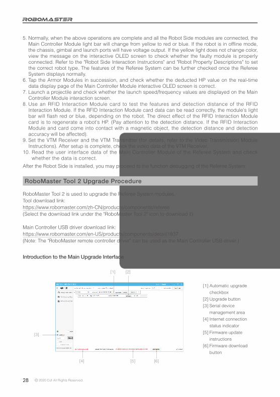
Introduction to the Main Upgrade Interface
[1] Automatic upgrade
checkbox
[2] Upgrade button
[3] Serial device
management area
[4] Internet connection
status indicator
[5] Firmware update
instructions
[6] Firmware download
button
[1] [2]
[3]
[4] [5] [6]
© 2020 DJI All Rights Reserved. 29
Upgrade Procedure1. Connect the Main Controller Module, the Power Management Module and the module to be upgraded,
and use a micro-USB data cable to connect your computer to the USB port of the Main Controller Module to supply power to the Robot Side.
2. Open the RoboMaster Tool 2 upgrade tool and check your Internet connection status.3. On the serial device management area on the left side of the main interface, select the correct serial
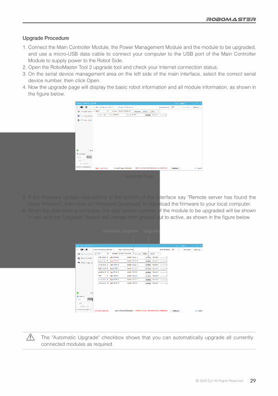
device number, then click Open.4. Now the upgrade page will display the basic robot information and all module information, as shown in
the figure below.
Upgrade Page
5. If the firmware update instructions at the bottom of the interface say "Remote server has found the latest firmware", then click on "Firmware Download" to download the firmware to your local computer.
6. When the download is complete, the app version number of the module to be upgraded will be shown in red, and the "Upgrade" button will change from grayed out to active, as shown in the figure below.
The "Automatic Upgrade" checkbox shows that you can automatically upgrade all currently connected modules as required.
Automatic Upgrade Upgrade

30 © 2020 DJI All Rights Reserved.
7. The upgrade page will display the basic robot information and the firmware information for all modules. Click the "Upgrade" button, as shown in the figure below.
8. When the upgrade progress bar has finished updating, the module firmware update is complete.

© 2020 DJI All Rights Reserved. 31
RoboMaster ServerThe Server is the control center of the entire Referee System. It collects data from all robots and Clients during the competition, visually presents the data to users, and automatically determines the outcome of the competition.
Go to https://www.robomaster.com/en-US/products/components/referee to download the Server.Running "RMServerStart.exe" will open the RoboMaster Server, log system, mini-map, and the RoboMaster Server UI at the same time.The entire page of the RoboMaster Server UI is shown as follows (Note: slight differences may appear between different versions):
Server Configuration
The computer host on which the RoboMaster Server is running must have the IP address set to 192.168.1.2 and any firewalls must be disabled. For other configurations, refer to "Setting up a LAN".
RoboMaster ClientAfter the Client runs the first-person view application and connects to the self-built server or competition server, the robot-related data uploaded by the Referee System can be viewed through the first-person view screen. Data includes the robot's current HP, real-time projectile initial firing speed and launch speed, a mini-map of the competition battlefield, the real-time power output of the chassis, and teammate information.Go to https://www.robomaster.com/zh-CN/products/components/referee to download the Client.
The full UI page is shown in the figure below:

32 © 2020 DJI All Rights Reserved.
Client Configuration
To connect the Client to the competition server, the PC host on which the Client is running must work in the same LAN as the Server. The Client can obtain the IP automatically.
Setting up a LANWhen the Main Controller Module on the Robot Side and the Server are using the same LAN, the Robot Side can be connected to the Server for online combat. The following steps demonstrate how to set up a LAN:1. Use a 2.4G wireless router (the Referee System only supports 2.4G) with a LAN port (a home router
can be used). Set the IP address to 192.168.1.1, customize the SSID, set the password to 12345678, select WPA2 for the encryption method, and enable the DHCP function.
2. Connect the host on which RoboMaster Server is running to the wireless router via a network cable and set the static IP address of the host to 192.168.1.2.
3. Connect the host on which the RoboMaster Client is running to the wireless router via a network cable and the IP address can be obtained automatically without manual setting.
4. Power the robot on to supply power to the Referee System. Following the "Wi-Fi Connection Settings" in "System Settings", connect the Robot Side to the wireless router. After connection, the Robot Side will be in the same LAN as the Server via Wi-Fi.
5. The RoboMaster Server runs on the Server PC. You can check the connection status of the robot on the Server side. If a LAN is set up, you can check Robot Side data on the Server side.

Email: [email protected]: http://bbs.robomaster.com
Website: http://www.robomaster.comTel: 0755-36383255 (Mon-Fri 10:30 am - 7:30 pm)
Address: Room 202, Floor 2, Integrated Circuit Design & Application Industrial Park,1089 Chaguang Road, Xili County, Nanshan District, Shenzhen City, Guangdong Province
WeChat Weibo