v10 com manual - mgl avionics
TRANSCRIPT

MGL Avionics
VHF Air band transceiver
V10
User and installation manual
Issue 1, March 2009

GeneralPlease read this manual before operating the V10 transceiverPlease include this manual if ownership of the V10 transceiver changes
Operational limitations, conditions and restrictions
Do not operate this device outside of its specified temperature range – this may result in malfunction or damage to the device.Observe the installation wiring diagrams. Incorrect wiring may damage this device.Never operate this device outside of its specified voltage range. Doing so may cause serious damage to this device.At all times ensure that no reverse power polarity is applied to this device. Reverse polarity will destroy this device.
This transceiver is designed to withstand the possible power surges that may be generated in a correctly wired power supply system in a typical aircraft. For this reason the transceiver may be left switched on when engines are started. Please note that the supply voltage may drop below minimum operating voltage during engine cranking. During this time operation of the radio will not be possible.
The V10 transceiver is not FAA certified for use in certified aircraft. This device may only be used in aircraft where such a device is permitted under local rules.Typically these rules permit operation in non-type certified aircraft such as home built and experimental or sport category aircraft.Limitations may exist on maximum altitudes a non-certified air band transceiver may not be operated above. Please check your local rules with the relevant authorities.
Use of this radio may be subject to a radio station license. Please contact your local radio frequency spectrum governing body (such as the FCC) as to the procedures required to obtain a radio station license.Operation of this transceiver may only be allowed by persons holding a valid radio license (restricted or full).
Please do not operate this transceiver illegally.
Please do not operate this transceiver in an environment or in conditions where its transmissions may cause interference with other electronic equipment or systems.
Never operate an air band radio without the required qualifications to do so.Never cause a nuisance to aircraft on the ground or in the air by misuse of this transceiver in any way.Never compromise the safety of other aircraft with lengthy transmissions. Keep your transmissions short and to the point following established air to air and air to ground rules and procedures.

FCC statementThis device complies with Part 15 of the FCC Rules. Operation is subject to the following two conditions: (1) this device may not cause harmful interference, and (2) this device must accept any interference received, including interference that may cause undesired operation.This transceiver has passed laboratory tests to FCC rules part 2, part 15 and part 87 as applicable.This transceiver is registered with U.S. FCC under the following FCC ID: WSJV10
TSO qualificationsThis transceiver is designed to meet he following TSO standards:TSO-C37D, TSO-C38D, TSO-C128
DO160 qualificationsThis transceiver is designed to the following EUROCAE ED-14D / RTCA DO-160D standards:Section 4: Category C1. No external cooling required.Section 5: Category CSection 6: Category ASection 7: Category B (shock and crash safety)Section 8: Categories R and USections 9-14: Category X – not requiredSection 15: Category ZSection 16: Category A and BSection 17: Category ASection 18: Category A and BSection 19: Category ZSection 20: Conducted category VSection 21: Category BSection 22: Power: Category A3C3, signals and digital comm: Category A1C1Section 23, 24: Category X – not required

Table of ContentsGeneral........................................................................................................................................2
Operational limitations, conditions and restrictions................................................................2FCC statement............................................................................................................................3TSO qualifications.......................................................................................................................3DO160 qualifications...................................................................................................................3The V10 transceiver introduction................................................................................................6The V10 Panel.............................................................................................................................7
FLIP-FLOP mode....................................................................................................................7Direct frequency entry mode...................................................................................................8Dual watch system..................................................................................................................8
Frequency displays.............................................................................................................9The status display...............................................................................................................9V10 voltage and temperature monitoring...........................................................................9Stuck PTT.........................................................................................................................10Transmit signal modulator................................................................................................10
The V10 menu structure............................................................................................................11The V10 buttons........................................................................................................................12
The “menu” button................................................................................................................12The “active” button................................................................................................................12The “VOL/SQL” button..........................................................................................................12The MHZ/KHZ/CH button.....................................................................................................13
Selecting frequencies................................................................................................................14The channel database...............................................................................................................14
Changing channels...............................................................................................................14The RX/TX bargraph.................................................................................................................15The menu system......................................................................................................................15
First level menu functions.....................................................................................................17Ambient noise suppression..............................................................................................17Program channels............................................................................................................18Contrast............................................................................................................................18Microphone level..............................................................................................................19Microphone bandpass filter..............................................................................................19PTT Mode.........................................................................................................................20Auxiliary input level...........................................................................................................20Scanning state on power up.............................................................................................20Setup menu entry.............................................................................................................20
Second level menu functions................................................................................................21Main + Standby / Main only / Standby only......................................................................21Invert off / invert on...........................................................................................................21TX MIC VOX / TX MIC HOT.............................................................................................22TX LOCK ON / TX LOCK OFF.........................................................................................22P-scan OFF / P-scan ON..................................................................................................22Direct FS / Flip-Flop FS....................................................................................................221 MIC Level / 2 MIC Level................................................................................................22COMM TX ON / OFF........................................................................................................23Default..............................................................................................................................23

Frequency lists..........................................................................................................................24Dual watch receiver operation..................................................................................................25Dual scan receiver operation....................................................................................................26Installation.................................................................................................................................27
General installation notes.....................................................................................................27D-15 connector pin out.........................................................................................................28Principal wiring diagrams......................................................................................................29Using two V10 transceivers in a dual watch configuration (1)..............................................30Using two V10 transceivers in a dual watch configuration (2)..............................................30Normal single transceiver installation...................................................................................31Dual transceiver installation..................................................................................................31Other installation options......................................................................................................31Connecting RS232 communication links..............................................................................32
Connecting a MGL Avionics NAV receiver.......................................................................32Using an external intercom system......................................................................................32
RF feedback – cause and elimination..............................................................................32Dimensions................................................................................................................................34MGL Avionics V10 transceiver binary communications protocol..............................................35
Version..................................................................................................................................35General.................................................................................................................................35
General message format:.................................................................................................35Commands:......................................................................................................................36Format of Acknowledge message (sent by transceiver)..................................................40Format of status message (sent by transceiver every 120mS)........................................40
Specifications............................................................................................................................41

The V10 transceiver introductionThe V10 is a VHF Airband transceiver with a 6W carrier power transmitter enclosed in a 3.1/8” standard aviation panel mount (front mount) of compact mounting depth and very light weight.A generously dimensioned LCD display provides clear frequency and function information. The receiver spans the frequency range from 108 to 136.975Mhz (includes NAV frequencies) while the transmitter covers the COM frequency range from 118 to 136.975Mhz.Up to 100 memory channels and 10 frequency lists are provided in addition to direct frequency selection. The V10 receiver is based on a commercial broadcast quality system in a dual superheterodyne configuration with a high first IF stage. Audio is demodulated using a synchronous demodulator resulting in very high receive audio quality.The receiver can be operated as dual frequency scanning radio.The transmitter is based on a PDMOS output stage using a class D fully digital modulator. Modulation is entirely under microprocessor control allowing excellent carrier modulation under all conditions. As a welcome side effect this results in a very power efficient transmitter.A unique, fully digital PLL operating at around 5Ghz is used as highly stable and spectrally very clean source as local oscillator and transmit frequency source. No frequency calibration is required during the lifetime of the V10 to remain within required tolerances.The V10 receiver and transmitter circuits contain zero adjustment points and no line-up procedure is required either during manufacture or during service life.All audio processing is done in software using a high performance microprocessor using digital signal processing principles. Conversion from and to analog is done using a 18 bit CODEC. A two circuit digital intercom system is included configured as pilot and passenger system. Several advanced intercom options are included, made possible by the software implementation of the system. Two independent ambient noise suppression systems are included, each can be adjusted for a wide range of applications.The V10 user interface is specifically designed to be used under difficult conditions such as found in open cockpit aircraft. Discarding common rotary knobs in favor of large, well spaced, tactile buttons allows convenient operation of the V10 even with gloved hands.The V10 further integrates very comprehensive digital communications links allowing remote control and downloading of frequency databases.

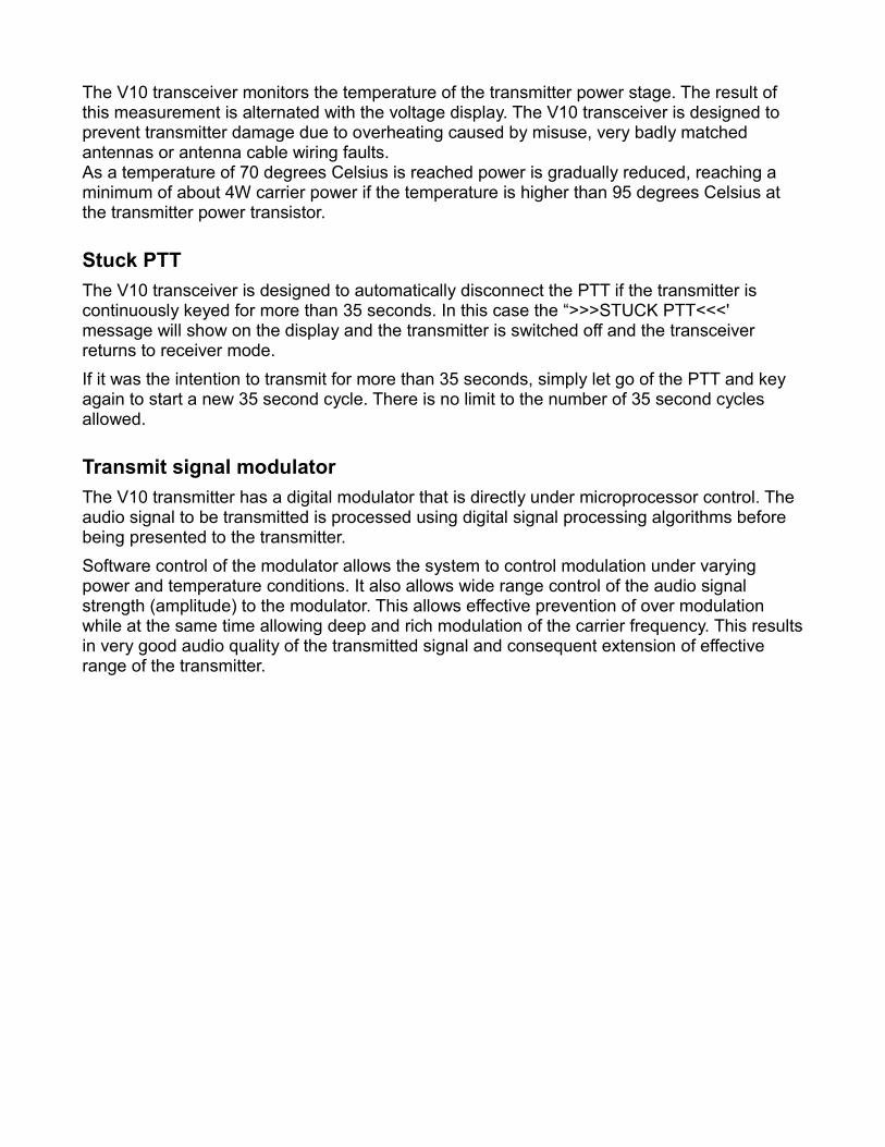
The V10 Panel
The above picture shows the V10 transceiver in its most typical application as “Flip-Flop” frequency selection system. The V10 transceiver can be operated in other modes depending on its setup and installation.
FLIP-FLOP modeIn this mode you change/edit the standby frequency while receive and transmit operate on the active frequency. Active and standby frequencies may be interchanged using the “Active”
Press this button toenter the menus. Here you will find many adjustments
and setups
Pressing this button exchanges active and
standby frequency. Note: holding this button
down enables further functions
The current active
frequency
Increasea value or
setting
Decrease a value or
setting
Select volume or squelch level to be
changed
Select MHZ, KHZ or channel to be changed. Hold down this
button for 2 seconds to change between MHZ/KHZ and Channel mode. Hold down this button for
1 second when in MHZ/KHZ mode to change between 50
and 25 KHZ tuning steps.
The current standby
frequency
Status bar showing volume or squelch level, voltage or transmitter temperature and active frequency
selection mode

button.Note: If scanning is enabled, it is also possible to receive on the standby frequency.
Direct frequency entry modeIn this mode, only the active frequency is shown. Standby frequency does not exist. All changes/edits are done directly to the active frequency. No scanning is possible.
Dual watch systemA dual watch system can be formed using two V10 transceivers (see installation section).This is similar to a single V10 operating in dual scan mode.
In effect, active and standby frequencies are spread over two transceivers making use of the second receiver in the standby system.The active system controls volume. The standby system controls its own squelch setting.The dual watch system can be operated from either panel however each system retains its own menu system.Memory channels from the active system are used. Memory channels on the standby system are not used. The standby systems transmitter is not used.It is possible to connect a dual watch system in a fully redundant way. In this case either system can be operated as a normal dual scan transceiver in case the other system is not functional.

Frequency displays
Frequencies are displayed as 6 digit numbers. The first three digits show the MHZ part of the frequency in the range of 108 to 136. The last three digits shows the KHZ part of the frequency. In case of the European 8.33Khz channel spacing, the frequency may be shown rounded to the nearest KHZ:Examples:122.008 = 122.00833 Khz131.533 = 131.53333 Khz118.292 = 118.29166 Khz
The status displayThe bottom section of the display contains a variable content status.
Pressing the VOL/SQL button will change between Volume and Squelch setting. If you press the VOL/SQL button to return from squelch setting to volume setting, the squelch will briefly open regardless of its setting (receiver static test).
V10 voltage and temperature monitoringThe V10 transceiver monitors the DC voltage at its supply terminals. The result of the voltage measurement is used to set the output power of your transmitter and is also used to control modulation of the transmit carrier to make optimal use of the available power.A voltage below 11.0V will result in a “>LOW<' indication alternating with the voltage display. Your V10 transceiver will be able to use the transmitter to below 10V. At 10V a useful 4W of typical carrier power is available (low voltage emergency operation). Full power is achieved at 13.8V and higher input voltages while rated power is achieved at around 13V typically (varies slightly between units and frequency tuned).
Current audio volume setting. Pressing the up/
down arrow key will change the volume.
DC voltage level at supply input, alternates
with internal temperature in degrees Celcius.
Frequency entry mode:50K tuning steps MHZ/KHZ25K tuning steps MHZ/KHZ
CHL ChannelsLST Frequency Lists
The V10 transceiver monitors the temperature of the transmitter power stage. The result of this measurement is alternated with the voltage display. The V10 transceiver is designed to prevent transmitter damage due to overheating caused by misuse, very badly matched antennas or antenna cable wiring faults.As a temperature of 70 degrees Celsius is reached power is gradually reduced, reaching a minimum of about 4W carrier power if the temperature is higher than 95 degrees Celsius at the transmitter power transistor.
Stuck PTTThe V10 transceiver is designed to automatically disconnect the PTT if the transmitter is continuously keyed for more than 35 seconds. In this case the “>>>STUCK PTT<<<' message will show on the display and the transmitter is switched off and the transceiver returns to receiver mode.If it was the intention to transmit for more than 35 seconds, simply let go of the PTT and key again to start a new 35 second cycle. There is no limit to the number of 35 second cycles allowed.
Transmit signal modulatorThe V10 transmitter has a digital modulator that is directly under microprocessor control. The audio signal to be transmitted is processed using digital signal processing algorithms before being presented to the transmitter. Software control of the modulator allows the system to control modulation under varying power and temperature conditions. It also allows wide range control of the audio signal strength (amplitude) to the modulator. This allows effective prevention of over modulation while at the same time allowing deep and rich modulation of the carrier frequency. This results in very good audio quality of the transmitted signal and consequent extension of effective range of the transmitter.

The V10 menu structureThe V10 transceiver provides setups and adjustments on two menu levels. The first level is accessed by pressing the “Menu” button. The second level contains setups that are typically only used once, during installation. These are accessed via the first level menu “setup” function.Menu functions shown inside are only available if enabled or required data is present.
Select channels / lists (if any lists loaded)VOX/VOGAD adjustmentsEdit memory channelsDisplay contrast adjustmentMicrophone levels (All or pilot if 2 levels enabled)Microphone level passenger (if 2 levels enabled)Auxiliary input level and mute adjustmentMicrophone bandpass filterScanning power up statePTT join or isolateEnter second level setup menu
Single/dual type operating modeTX audio phase reversalTX HOT microphone or VOX/VOGADTX lock on RX enablePriority scan on active enableFlip-Flop or direct frequency modeOne or two microphone level adjustmentsSet unit to factory default

The V10 buttons
The “menu” buttonThe menu button allows you to enter the menu system at any time. Here you will find access to less often used functions such as setting intercom VOX or audio levels and other functions. Via the menu system you can also enter the setup system where you can select many operational options for the transceiver.
The “active” buttonPressing this button exchanges active and standby frequencies.With a normal setup, you edit the standby frequency (change frequencies either by direct entry or channel selection).Note: It is possible to select the transceiver to operate in “direct frequency mode” in this mode you will only see a single frequency on the display which is your active frequency. You can directly change this frequency.Note: Holding down this button for 1 second will activate the scanning system (both active and standby frequencies are scanned rapidly for incoming transmissions). If the scanning is enabled, this will disable the scanning. Scanning is indicated by a flashing “S” between the active and standby heading:
You will hear a short burst of beeps when activating or deactivating the scanning so you do not have to look at the display. You will get three beeps if the scanning has been enabled and two beeps if it has been disabled.Note: Holding down this button for 3 seconds will automatically set the active frequency to the emergency broadcast channel on 121.5 Mhz.
The “VOL/SQL” buttonThe transceiver defaults to the volume bargraph display. In this mode pressing the up or down arrow button will adjust the headset volume.Pressing this button will change to the squelch bargraph and this will allow you to set the desired squelch level.Adjust the squelch level such that the static noise from the receiver is just squelched out. Adjusting this too high may result in weaker transmissions not being received. Adjusting this too low may result in static noise breaking though at times.Note: This button is also used for a quick receiver check: Press the button to show the squelch level and then press it again to return to the volume level. This will open the squelch for about two seconds regardless of the squelch setting so you can verify receiver static (which is a good indication that the receiver is working).

The MHZ/KHZ/CH buttonPress this button to select to change the standby frequency or active frequency if direct frequency mode is being used.The V10 transceiver operates either in MHZ/KHZ or channel entry mode.Holding the MHZ/KHZ/CH button down for two seconds changes the entry mode.
In MHZ/KHZ mode you use the MHZ/KHZ/CH button to change entry between MHZ or KHZ. In Channel mode you use the MHZ/KHZ/CH button to change either channel number 10's or channel number 1's.When in either of the above two entry modes (channel 1's or channel 10's), pressing the MHZ/KHZ/CH button briefly will flip the entry mode between 1's and 10's.Pressing and holding down the MHZ/KHZ/CH button for one second will change the entry mode to MHZ/KHZ.
Transceiver is in channel entery mode. Pressing MHZ/KHZ/CH
will allow you to change channels
Pressing the up/down arrow buttons will change channel
number 1's
Pressing the up/down arrow buttons will change channel
number 10's
Pressing and holding the MHZ/KHZ/CH button for one second will change to 25KHZ
tuning steps (8.33KHZ for European models).
Pressing and holding the MHZ/KHZ/CH button for one second will change to 50KHZ
tuning steps.
Pressing the up/down arrow buttons will
change the MHZ of the frequency being
entered. Pressing MHZ/KHZ/CH will
change to KHZ entry.
Pressing the up/down buttons will change the
KHZ of the frequency being entered.
Pressing MHZ/KHZ/CH will change to MHZ entry.

Selecting frequenciesRegardless of “direct frequency” or “flip/flop frequency” mode, setting a frequency is done by pressing the MHZ/KHZ/CH button until the desired entry you want to change is flashing on the display: Example “set MHZ”:
While the desired entry is flashing, you can change the number using the up and down arrow buttons.Note: KHZ rolls over without changing the MHZ value. If 50 Khz steps are used, pressing the up arrow button will change from a frequency display of 124.95 to 124.00. 124.00 with pressing the down button will change to 124.95. This may be used to speed up KHZ selection.
The channel databaseThe V10 transceiver contains up to 100 user programmable frequencies, each with name and function designator using alpha numeric characters.In addition, a further 10 frequency lists are provided with 20 frequencies each. These may be set remotely if the system is connected to an EFIS or compatible GPS. Typically, each of these databases would contain frequencies related to an airport and each of these databases is identified by the name of the airport. These databases are loaded at runtime from a compatible EFIS and are lost if power is removed. If at least one database is loaded, it can be selected as first menu item. If selected it will replace the internal 100 channel database until it is deselected using the same menu function.Note that this functionality is available only if the EFIS/GPS uses Garmin SL30 or SL40 communications. MGL Avionics EFIS systems do not use this function as the frequency selection has moved to the EFIS itself.
Changing channelsPress the MHZ/KHZ/CH button until the word “Channel” appears as shown below. Then you can select channels using the up and down arrow buttons.Note: The channel selection will roll over from 100 to 1 or from 1 to 100.Note: If Airport frequency lists have been uploaded from a compatible EFIS and such a list has been activated by menu function, only 20 channels will be selectable from the currently active list (the list size is determined by the SL30 and SL40 communications protocol from 1 to 20 entries).

The RX/TX bargraphThe V10 transceiver contains a bargraph in its main display that during RX shows the relative signal strength of a received transmission. Due to the good receiver sensitivity signals of medium strength will be able to fill the bargraph.During TX the bargraph shows your voice modulation of the actual transmit carrier. In effect this is a visual side tone. Using this you have a tool to judge how well the signal from your microphone is modulating the carrier. Note that this bargraph does not just show you the level from your microphone – this is the actual signal that is being transmitted.A good modulation will cause the bargraph to just touch the right hand side of the display for the loudest part of your transmission, often this is achived with click (“T”) or “SHH” voice sounds. The normal parts of your voice during transmission would show up around 50% modulation level.The modulation level should be adjusted using the microphone level adjustment in the menu. If you change headsets to another type, check the microphone level first before you use it. The microphone level adjustment menu function has a very convenient readout of your level making adjustment easy and precise.
Receiving transmission of moderate strength
Transmitting with good modulation at louder parts of voice
The menu systemEntering the menu system is done by pressing the “Menu” button.The menu consists of a two level system. Common use selections and setups are concentrated in a first level menu system while rarely used setups are found under the “setup” menu which is accessible as a first level menu item.
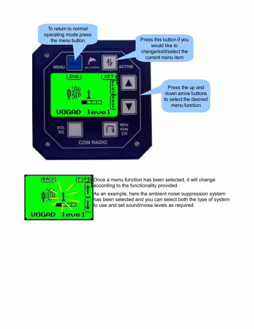
Once a menu function has been selected, it will change according to the functionality provided.As an example, here the ambient noise suppression system has been selected and you can select both the type of system to use and set sound/noise levels as required.
Press the up and down arrow buttons to select the desired
menu function
Press this button if you would like to
change/edit/select the current menu item
To return to normal operating mode press
the menu button

First level menu functionsThis chapter describes the various first level menu functions provided in the V10 transceiver.
Ambient noise suppression
Your V10 transceiver provides four different ambient noise suppression systems. These can be selected using the “Type” selection.The up and down arrow buttons can be used to select the strength or effectiveness of the selected system.
● VOGAD systemThe VOGAD system is a propriety system developed by MGL Avionics. This system uses gain shaping using digital audio processing. Here the voice strength envelope is detected and used to modulate the gain of the microphone amplification system. A level setting of 1 is suitable for most applications. Three further levels are provided with different characteristics. The system should be selected such that ambient noise is sufficiently suppressed while voice comes through loud and clear. It is important to set your microphone gain not too high to allow correct match of the microphone level to the system. A high level of gain may allow noise to pass the threshold.A correctly setup VOGAD system will cause your microphone to become very directional so it needs to be placed directly in front of your mouth.
● VOX systemThis system simply switches your microphone off if the level of sound received by the microphone is below a preset level. The switching is done in a digitally controlled “soft” manner so no clicks are audible.Adjust the level such that ambient noise is just less than what is needed to open the microphone. If the level is set too high, you may find that parts of your first syllable are not sufficient to open the microphone.

Program channels
This function, if selected will enter the memory channel programming system.Memory channels can be programmed using this function or they can be downloaded from a PC using the provided software.
The V10 provides 100 channels for pre-programmed frequencies. Each channel contains frequency, name of the frequency (for example airport name) and type of the frequency (for example “Tower”).Name and type can be up to 6 characters long.
Use the active/standby button to move the highlight (inverted part of the display) to the desired line for editing.Channel selected:Use the up and down arrow buttons to select the channel to edit.Frequency selected:Use the MHZ/KHZ/CH key to select change of MHZ or KHZ (the MHZ or KHZ part will flash to indicate which is selected.Use the up and down arrow buttons to edit the frequency.Holding down the MHZ/KHZ/CH button for 1 second will switch between 25 and 50 Khz steps.Name or Type selected:Use the MHZ/KHZ/CH button to select the character position to edit.Use the up and down arrow button to change the character.Press the “Menu” button to return to the menu when you are finished editing channels.
Contrast
Adjust the display contrast. A value of between 30 and 40 is suitable for most environments. A lower value results in a lighter display while a higher value results in a darker display. Adjust the contrast such that dark areas are fully saturated while light areas do not show any darkening.

Microphone level
This function allows you to adjust your microphone level. A bargraph is provided so you can adjust to the correct level. The correct level is achieved if most of the time, while you are speaking normally into the microphone, the bargraph remains between about ½ to ¾ of the range with excursions all the way to the right only during very loud parts of your voice or “click” sounds.
Please note: The level shown is that of the Pilot microphone input. No level is shown for signals received from the passenger microphone.This adjustment sets both the pilot as well as the passenger microphone amplifier gain levels.Correct adjustment of this level is important. It influences correct operation of the ambient noise suppression systems and also influences correct modulation levels of your transmitter.Note: By design your transmitter cannot be over-modulated if levels are set too high, however, sound quality may suffer.Using independent level settings for pilot and passenger microphone circuits:The second level menu system contains a setting to enable independent level adjustments for pilot and passenger microphone circuits.If enabled, two level adjustments are made available:
Microphone bandpass filterFor operation with high ambient noise levels an additional voice bandpass filter can be engaged for both pilot and passenger microphone circuits.This can help reduce the effects of unwanted noise, in particular at very low and very high frequencies. This filter has a sharp cutoff for frequencies below 500 Hz and above 2.4KHz.

PTT ModeThe V10 transceiver has two PTT inputs, one for the pilot circuit and one for the passenger circuit (PAX).You can select to join or isolate the PTT and micrphones during transmit.If you have selected “Join”, both microphone circuits are active during transmit regardless of which PTT is activated.If you have selected “Isolate”, only the microphone circuit
related to its PTT will be allowed if the PTT is active – the other microphone will be muted.
Auxiliary input levelYou can connect an EFIS voice alert or other sound system (music) to the auxiliary inputs of your V10.You can choose two levels:Open: This level is applied if no sound is received from your microphones.Mute: This level is applied if sound is received on either of your microphone circuits.
Depending on the setting, you can select the same level (external sound remains unchanged if you speak into the microphone), differing levels (external sound fades to a lower level if you speak into the microphone) or you can select that the external sound is completely muted if you speak into the microphone.The external sound level is not switched between these two levels but is faded between these levels (slow, pleasant fading in and out of the external sound).
Scanning state on power upSelect if you would like your V10 transceiver to power up with scanning enabled or disabled.Scanning is only applicable if you are operating a single system in active/standby mode and direct frequency entry is disabled.Scanning will continuously check active and standby frequencies for reception.
Setup menu entrySelect the secondary setup menu for basic setups and operational options. In this menu you will find setups that are only rarely used, usually only when you first install your transceiver.Secondary setup menu options are listed in the next chapter.

Second level menu functionsThis chapter describes the various second level menu functions provided in the V10 transceiver.The second level menu is accessible via the first level menu “Setup” selection.
Main + Standby / Main only / Standby onlySelect the basic operation mode for this transceiver. If you have a single transceiver or a dual transceiver that are completely independent, select “Main+Standby”.If you are using a dual transceiver setup interconnected via the airtalk link, select one transceiver to be your “main” unit and the other to be the “standby” unit.In this configuration using two transceivers, you have full dual watch operation (as opposed to dual scan with a single transceiver). With this system, operation is similar to a single transceiver operating in active/standby mode except that active and standby are spread over two transceivers. In effect you are using the standby transceivers receiver only to create a single dual watch system.It is also possible to install your two systems in such a way that they can each be used as full function systems in case one of your transceivers becomes nonoperational.
Invert off / invert onThis function allows you to invert the phase of your microphones by 180 degrees. This can be useful if your setup is suffering from RF feedback issues. In this case, during transmission,
Use the up/down buttons to select the desired function to change and then press the “active” key to select your
option.

RF from your antenna may be injected into your microphones, wiring or additional audio panels or external intercom systems and partly demodulated due to non-linearities in the audio inputs. This is somewhat similar to audio feedback that may occur on stage with a microphone and sound system.Inverting the phase is not a real fix for this, (this should be corrected by proper installation) – however it is a useful feature nevertheless that can help, in particular if you are using an external intercom system or audio panel and the phase relationship is not known.
TX MIC VOX / TX MIC HOTSelect if during transmission you would like the noise ambient noise suppression system to remain active or if you want the microphone to be “hot”, i.e. continuously active during the time of transmission.If you are using the VOGAD system, we recommend to set this to “TX MIC VOX”. If you are using the traditional VOX system, we recommend to set this to “TX MIC HOT”.
TX LOCK ON / TX LOCK OFFSelect if you would like the transceiver to prevent transmission if it is currently receiving on the active frequency.Select “LOCK ON” if the PTT should be disabled if there is a current reception on the active frequency that is above the current squelch level in signal strength.
P-scan OFF / P-scan ONSelect if you would like to enable the priority scan feature.This is applicable only to systems set to “main/standby” mode with direct frequency selection off.If you have scanning enabled (enable/disable by holding the active button down for 1 second), and you are currently receiving on the standby channel, the reception will break for short intervals to allow the system to check the active channel for a signal. If a signal is found o the active channel, reception on the standby channel is canceled and the active channel is received. Once reception on the active channel terminates, scanning continuous.
Direct FS / Flip-Flop FSSelect if you would like to use direct frequency selection or the normal active/standby “flip-flop” frequency selection system.This setup is only applicable if you are using the transceiver in “main/standby” mode.With direct frequency selection you change the frequency of the active channel and no standby channel exists. Also there is no scanning.
1 MIC Level / 2 MIC LevelSelect “2 MIC Level” if you need independent level controls for pilot and passenger microphone circuits.

COMM TX ON / OFFIf you are using a dual radio setup or are using a remote head or other remote function to control the radio you need to select this function to “on”. This will enable continuous transmission of the radios status on both RS232 serial interfaces as well as the airtalk interface. This function is “off” as a default.There is a possibility of slight microphone interference related to the transmission of digital data if installation is not optimum or you have unterminated (open) audio inputs such as the auxiliary input or insufficiently shielded microphone cables. If you do not have a need for the transmission of the radio status data, we recommend that you set this function to “off”.Please note that with this function set to “off” remote control of your V10 radio to set frequencies from a connected EFIS system is still possible.
DefaultThis function ask for confirmation before reseting all settings to factory default.Items NOT affected are:a) Memory channelsb) Current active and standby frequencies

Frequency listsIf you have your transceiver connected to a Garmin SL30 or SL40 compatible frequency source (such as an EFIS or aviation GPS), it may be possible for these devices to upload frequency lists to your transceiver.The Garmin frequency list system consists of up to 10 lists with up to 20 frequencies each. Each list is normally used to contain the frequencies for one airport. Each frequency is marked by function (such as tower, ground, etc).Each list is identified by a four character identifier.
If at least one list containing at least one frequency has been uploaded to your V10 transceiver, you will be presented with a new menu entry (first level menu).This menu function allows you to select either the normal 100 channel memory to be used for channel selection or you can select from any of the uploaded frequency lists. For example the next picture shows the selection for a list called “KLAX”, Los Angeles International.
Select either “Channels” to use the normal 100 channel memory or select one of the uploaded lists as you require.List frequencies can be selected in the same way that you would access normal channels. Each frequency will be displayed with the list name and frequency function.Note: If you switch your V10 transceiver off, uploaded frequency lists are cleared. Your frequency source (EFIS, GPS) needs to upload the lists again after you switch on your V10 transceiver.Note: MGL Avionics EFIS systems do not use frequency lists. This functionality has moved into the EFIS and direct frequency selection via the EFIS is used.

Dual watch receiver operationDual watch configuration requires two V10 transceivers wired in one of the two possible methods shown in the installation section of this manual (simple or redundant system).One V10 is configured as active frequency system while the other system is configured as standby system. In principle, the two V10 transceivers operate very similar to a single V10 configured as active/standby system but rather than using a dual scan system, a dual watch system is possible as a second receiver is available.The standby system never transmits.
● Volume is set on the active system● Both transceivers have their own squelch level settings● Frequency is changed on the standby system● Direct frequency entry is not available in this mode● ACTIVE, MHZ,KHZ,CH and UP/DOWN buttons function interchangeably on both
systems● Auxiliary audio is fed to the standby system and is routed to the active system if no
reception on the standby system is present● Standby volume setting and active auxiliary level settings are fixed and cannot be
changed● Reception on the active frequency always has priority

Dual scan receiver operationA single V10 transceiver can operate in dual scan mode. In this mode the receiver rapidly scans between active and standby frequencies. If either frequency contains a signal greater than the squelch level, scanning stops and the receiver locks onto this frequency. Once reception is terminated, scanning resumes.Scanning is enabled or disabled by holding the ACTIVE button down for one second (holding this button for three seconds will set the active frequency to the 121.5Mhz emergency frequency.Scanning is indicated by a flashing “S” in the header bar.
Scanning may be performed either in priority or non-priority mode. You select this in the second level menu. In non-priority mode active and standby frequencies have equal priority and reception will be handled on a first come, first serve bases.In priority mode, if reception is on the standby frequency, the reception will briefly interrupt for a very short interval once every second to allow the radio to check the active frequency for reception. If the active frequency is receiving a signal above the squelch threshold, reception switches to the active channel unconditionally.A further, related setup exists in the first level setup menu. Here you can select if scanning should be enabled when power is applied to the V10.

InstallationThis chapter describes the various installation options for the V10 transceiver.
General installation notesInstallation should be performed by a qualified aircraft electronics technician.All soldering using acceptable electronic fluxed solder wire. Solder joints are required to be of high quality to acceptable standards.All wiring external to the V10 transceiver to conform to relevant aircraft standards. Flame proof or flame retardant insulation to be used on all wiring.Installations must conform to regulations in force in your country.It is recommended that shielded audio cables are used for all audio signal connections. Using unshielded cables may result in interference.It is recommended to use shielded cables for all digital communications links to prevent interference.Choose suitable power cable of sufficient diameter to carry the maximum expected current to the V10 transceiver (1.5A maximum).It is mandatory to install a 2.5A-5A slow blow fuse or equivalent circuit breaker in line to the supply of the V10 transceiver.Never share power to a RF device with sensitive equipment such as GPS receivers and EFIS systems. Do route separate grounds and power supply rails to the V10 transceiver.RF cable must be good quality RG58 or equivalent cable. Choose a low loss cable if you need a long connection to your antenna.Ensure that the antenna cable has a correctly fitted BNC connector. Ensure in particular that no short exists either inside the BNC connector or at the antenna side of the cable. A shorted cable may result in poor performance and may damage your transmitter.Never route your antenna cable in a bundle with other wires. Never bend your antenna cable sharply as this degrades its function as transmission line at that point.After installation verify proper operation of the V10 transmitter using a suitable RF power meter with SWR readout. Ensure that the antenna is well matched and is able to radiate the available RF power generated by the V10. Reflected power due to poor antenna match or termination enters your aircraft ground system and may cause interference with other systems. Before operating the V10 transceivers transmitter, ensure that microphones are operational and levels have been setup correctly (first level menu – microphone level setup). If using microphone and headphone sockets – do not connect the metal body of these sockets to airframe or other grounds via a metal mounting surface as this can result in microphone and audio interference. Ensure that all electrical connections of the sockets remain isolated !

D-15 connector pin outThe V10 transceiver provides all low frequency signal and power connections on a female D-15 connector.
All audio connections use a common audio ground. Do not connect the audio ground to supply ground or aircraft grounds as this may introduce interference.Power requirement is a clean DC supply of 12V to 24V nominal. DC voltage may not exceed 28V.A single audio output is provided able to drive a 8 ohm speaker or up to 20 standard aviation 600 ohm headsets.A two circuit intercom circuit is provided. One circuit is intended as pilot circuit and the second circuit is intended as passenger circuit. It is permissible to connect several microphones to each circuit in parallel. In this case it is recommended that identical headsets are used.Two audio grounds are provided. It is recommended to use one for microphone grounds / auxiliary input ground and the other for headset ground. Two PTT inputs are provided. To activate a PTT, connect the PTT input to power supply ground or audio ground. Airframe ground may also be acceptable. One auxiliary audio input is provided. The input can be used to connect to a music source (CD or MP3 player) or EFIS voice alert. It is possible to connect two sources by coupling these to the single input using 4K7 (4700) ohm resistors in each feed, joining at the auxiliary input.Two independent RS232 serial communications ports are provided. These are used to connect to two independent EFIS systems for remote control of the V10 transceiver. These ports are equivalent and are interchangeable.One airtalk LAN communications link is provided. This is used to interconnect two V10 transceivers to form a single dual watch system.

Principal wiring diagrams
Use this diagram to wire headsets that provide built in PTT buttons.Please note use of shielded audio cable
Use this diagram if you plan on using independent PTT switches. Here both pilot and passenger PTT are shown. The passenger PTT is optional.Please note use of shielded audio cable. It is recommended to use shielded cable on PTT as well, in particular if long cables are needed.
This diagram shows power and communications links. Communications links are optional.It is recommended to use shielded cables for RS232 links.A 2.5A – 5A circuit breaker or fuse must be installed. This is mandatory.
This diagram shows connection of the auxiliary audio input.

Using two V10 transceivers in a dual watch configuration (1)
Using two V10 transceivers in a dual watch configuration (2)

Normal single transceiver installationThis installation is used if you have a single V10 transceiver and will be operating in Main/Standby mode (set this in the secondary setup menu).This is the normal mode of operation for most installations.You need to connect the following:
● Supply voltage (typically 12V) positive● Supply ground (negative)● Pilot microphone and headset● Pilot PTT contact● 50 ohm antenna tuned to the VHF airband via 50 ohm RG58 or equivalent cable
In addition you may connect the following optional items:● Passenger microphone and headset● Passenger PTT contact● One or two auxiliary audio sources (or one stereo source) ● One or two RS232 connections to EFIS systems (if used)
Dual transceiver installationTwo V10 transceivers may be connected to each other using the airtalk connection.Using this, one receiver is set to “main only” while the other is set to “standby only”. These modes are selected in the secondary setup menu.The standby system is used as a receiver only. It is possible to connect headsets in parallel with the main system as well as parallel connection of the PTT inputs. In this case it becomes possible to use the standby system as a redundant transceiver should the main system fail for any reason.Using a system in this manner allows the creation of a full dual watch system (as opposed to the dual scan system possible with a single transceiver). Two frequencies are monitored. The audio signal from the standby system is routed to the main system “auxiliary input”. Any auxiliary audio sources (music etc) are connected to the standby system and these signals are routed through to the main system if no RX is taking place on the standby system.The dual transceiver installation can be done either in a simple mode requiring minimal wiring or it can be wired as a fully redundant system. In the latter case, it becomes necessary to be able to switch a few signal wires using a panel mount multi-pole switch to switch between normal operation and redundant operation for the standby system.
Other installation optionsIf you are using a suitable audio panel and two V10 transceivers, you can wire these independently to the audio panel. In this case you can operate each radio either using direct frequency selection or flip-flop frequency selection as you require (select this operating mode in the secondary setup menu).

Connecting RS232 communication linksThe V10 transceiver provides two RS232 communication links, each with a TX and RX line. Each of the two RS232 links operates independent from the other using the same communication protocols. This allows connection of the V10 two two independent EFIS systems for full redundancy.Connect the TX line of the V10 to the RX line of the EFIS and the RX line of the V10 to the TX line of the EFIS. Usage of shielded cables is recommended. Connect the shield to either the ground of the EFIS or the ground of the V10. Do not connect both as this may create a ground loop. EFIS and V10 should share ground at the same potential (typically both have grounds wired to a common distribution point or the negative of the battery.
Connecting a MGL Avionics NAV receiverShould you be using a MGL Avionics NAV receiver (VOR, ILS and glideslope), connect the TX lines of both the V10 and the NAV receiver together. Also connect the RX lines in similar fashion.Connecting two TX lines together is not normally done with RS232 communications, however your V10 transceiver and the MGL NAV receiver have special provision for this. If wired together in this fashion, the two systems behave compatible to a Garmin SL30 NAV/COM system.The MGL Avionics NAV radio also has two RS232 links and you can join both in this fashion to the V10 radio and then to the EFIS system(s).
Using an external intercom systemIf you are using an external intercom system that provides its own VOX or ambient noise suppression system, it may be required to switch the built in VOX or VOGAD system off. You switch this off by setting the level of the chosen system to zero (value displayed: OFF). You select this in the first level menu system.You may also need to experiment with the signal phase inversion function (second level menu system) if you are experiencing RF feedback issues.
RF feedback – cause and eliminationRF feedback is a phenomena very similar to microphone feedback on a sound stage. The modulated RF signal during transmission is received by your microphones or microphone cables and routed to the input of your intercom system or V10 transceiver.Here, some of the modulated signal may be demodulated by non-linearities in the system, particularly if the received RF is very strong (typically several volts).This creates a common feedback loop that in a mild form will create an echo similar to “bathroom sound” and in severer cases will cause squealing or other undesirable effects.On of the most common causes for this is missing microphone cable shields due to broken wires or poor quality or unsuitable microphone cables.

Sometimes very close proximity of the transmitting antenna to headsets or other aircraft wiring may be the cause, often with more powerful transmitters like you find in the V10.In difficult cases, use of ferrites placed at strategic locations over your microphone and headset cables may help block RF from traveling on these cables. Ensure you use ferrites made to operate in the 100-150Mhz frequency band for this to be effective.Never route your antenna cable inside a bundle with other wires in your aircraft. Keep your antenna cable well separated from all other cables.

Dimensions

MGL Avionics V10 transceiver binary communications protocol
VersionThis document contains preliminary information on the binary communications protocol used by MGL Avionics VHF airband transceivers. It is applicable to panel mount as well as remote units that are controlled via passive panels or EFIS systems.
MGL Avionics does not guarantee correctness of this document. MGL Avionics reserves the right to change any part of the specification at any time.Please contact MGL Avionics for a current copy of this specification if you intend using it for your project.
GeneralCommunications takes place via RS232.
9600 Baud8 Data bits1 Stop bitNo parity
The transceiver transmits regular status messages containing sufficient information to build a typical display image. The status message is transmitted every 120mS.Messages to the transceiver consist of commands. Most commands result in transmission of an acknowledgment when the command has been received with a matching checksum. Exceptions to this are the PTT command (no response) and the request channel command which responds with channel data.PTT command has to be sent every 100 mS to keep PTT active.
Command messages containing frequencies that are not within the permitted airband are ignored and not acknowledged.
Most MGL radios have two RS232 communication links. Both links accept the same protocol and messages may be sent simultaneously via both links. This allows a redundant communications link to be established via two EFIS systems. It is recommended that only one EFIS system controls the transceiver while the other will take control in case the first one has a failure.
Note: The RS232 links also accept parts of the Garmin SL30 and SL40 communications protocols. Functions supported are frequency lists and direct selection of active and standby frequencies. Please view Garmin documentation on message formats. Garmin messages may be used at any time and may be interspaced by MGL binary protocol.
General message format:
$02 STX$05 DLE

CC CommandD0 1 to n bytes of data...DnCKS Checksum
Checksum is a linear XOR of the message contents from Command to the last data byte.The result of this is XOR'ed with the value of $55
Commands:
$00 Set active frequencyD0 Frequency in Khz, binary, LSB first.... Sets frequency is TX is not active, if active will cause change of frequencyD3 to new value when TX ends.
Note: Frequency must be a valid frequency in the range of 108.000 Mhz and 136.975Mhz. Frequency must be dividable by 25. Invalid frequencies will be ignored and no acknowledge will be sent for the message.
Sends acknowledge when message received OK
$01 Set standby frequencyD0 Frequency in Khz, binary, LSB first....D3
Note: Frequency must be a valid frequency in the range of 108.000 Mhz and 136.975Mhz. Frequency must be dividable by 25. Invalid frequencies will be ignored and no acknowledge will be sent for the message.
Sends acknowledge when message received OK
$02 Increase volume (typical 1.5dB)D0 Don't care data value (recommend to set to zero)
Sends acknowledge when message received OK
$03 Decrease volume (typical 1.5dB)D0 Don't care data value (recommend to set to zero)
Sends acknowledge when message received OK
$04 Set volumeD0 Volume value 0-31 (lowest to highest)
Sends acknowledge when message received OK

$05 Increase squelchD0 Don't care data value (recommend to set to zero)
Sends acknowledge when message received OK
$06 Decrease squelchD0 Don't care data value (recommend to set to zero)
Sends acknowledge when message received OK
$07 Set squelchD0 Squelch value 0-31 (lowest to highest)
Sends acknowledge when message received OK
$08 Set scanning on/offD0 0 = scanning off
1 = scanning onThis message has an effect only if a single transceiver set to operate inmain/standby mode is used.
Sends acknowledge when message received OK
$09 Program channelD0 Frequency in Khz, binary, LSB first.... Sets frequency is TX is not active, if active will cause change of frequencyD3 to new value when TX ends.N0 Frequency name. Six ASCII characters, pad with space ....N5F0 Frequency function. Six ASCII characters, pad with space....F5C0 Channel to program, 0-99 (channel 1-100)
Sends acknowledge when programming complete
$10 Request channel dataD0 Channel number 0-99 (channel 1-100)
Responds with channel data message:
$02 $05 $01 D0 D1 D2 D3 $06 N0 N1 N2 N3 N4 N5 $06 F0 F1 F2 F3 F4 F5 XX XX CKS
D1-D4 = Frequency in KhzN1-N5 = Frequency nameF0-F5 = Frequency function
XX = don't care
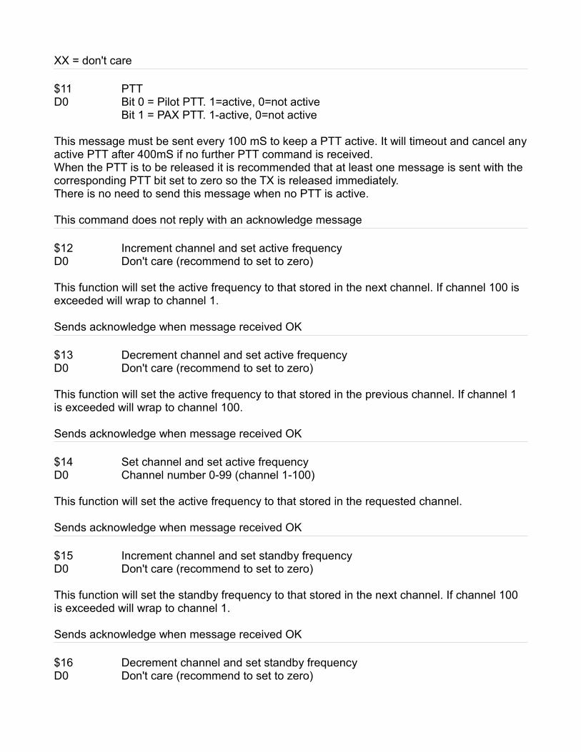
$11 PTTD0 Bit 0 = Pilot PTT. 1=active, 0=not active
Bit 1 = PAX PTT. 1-active, 0=not active
This message must be sent every 100 mS to keep a PTT active. It will timeout and cancel any active PTT after 400mS if no further PTT command is received.When the PTT is to be released it is recommended that at least one message is sent with the corresponding PTT bit set to zero so the TX is released immediately.There is no need to send this message when no PTT is active.
This command does not reply with an acknowledge message
$12 Increment channel and set active frequencyD0 Don't care (recommend to set to zero)
This function will set the active frequency to that stored in the next channel. If channel 100 is exceeded will wrap to channel 1.
Sends acknowledge when message received OK $13 Decrement channel and set active frequencyD0 Don't care (recommend to set to zero)
This function will set the active frequency to that stored in the previous channel. If channel 1 is exceeded will wrap to channel 100. Sends acknowledge when message received OK
$14 Set channel and set active frequencyD0 Channel number 0-99 (channel 1-100)
This function will set the active frequency to that stored in the requested channel.
Sends acknowledge when message received OK
$15 Increment channel and set standby frequencyD0 Don't care (recommend to set to zero)
This function will set the standby frequency to that stored in the next channel. If channel 100 is exceeded will wrap to channel 1.
Sends acknowledge when message received OK $16 Decrement channel and set standby frequencyD0 Don't care (recommend to set to zero)

This function will set the standby frequency to that stored in the previous channel. If channel 1 is exceeded will wrap to channel 100. Sends acknowledge when message received OK
$17 Set channel and set standby frequencyD0 Channel number 0-99 (channel 1-100)
This function will set the standby frequency to that stored in the requested channel.
Sends acknowledge when message received OK
$18 Flip active and standby frequenciesD0 Don't care (recommend to set to zero)
Sends acknowledge when message received OK
$19 Remote controlD0 CommandThis message enables simple remote control using a one byte command. This message does not result in an acknowledge.Command0 - Increment active frequency MHZ (will wrap)1 - Decrement active frequency MHZ (will wrap)2 - Increment active frequency KHZ (wraps within current MHZ)3 - Decrement active frequency KHZ (wraps within current MHZ)4 - Increment standby frequency MHZ (will wrap)5 - Decrement standby frequency MHZ (will wrap)6 - Increment standby frequency KHZ (wraps within current MHZ)7 - Decrement standby frequency KHZ (wraps within current MHZ)8 - Increment active channel (wraps (Lists do not wrap))9 - Increment active channel 10's (wraps (Lists do not wrap))10 - Decrement active channel (wraps (Lists do not wrap))11 - Decrement active channel 10's (wraps (Lists do not wrap))12 - Swap active/standby frequency13 - Volume up14 - Volume down15 - Squelch up16 - Squelch down17 - Increment KHZ 100's active (wraps within current MHZ)18 - Decrement KHZ 100's active (wraps within current MHZ)19 - Increment KHZ 100's standby (wraps within current MHZ)20 - Decrement KHZ 100's standby (wraps within current MHZ)21 - Press Menu key22 - Press Active key23 - Press Up key

24 - Press down key25 - Press MHZ/KHZ/CH key26 - Press VOL/SQL key
Format of Acknowledge message (sent by transceiver)$02 $05 $06 $53 (full message including checksum)
Format of status message (sent by transceiver every 120mS)$02 STX$05 DLE$00 Message typeF1 Flags
Bit 0 – 1 =TX is activeBit 1 – 1 =Scanning is activeBit 2 – 1 =RX on active frequencyBit 3 – 1 =RX on standby frequency
D0 Current volume 0-31D1 Current squelch 0-31A0 Active frequency in Khz....A3A0 Standby frequency in Khz....A3C0 Active channel 1-100 (0 if current frequency not in channel database)C1 Standby channel 1-100 (0 if current frequency not in channel database)L0 Active RX level 0-63 (for bargraph display)L1 Standby RX level 0-63 (for bargraph display)T0 TX modulation level 0-63 (for bargraph display)N0 Active frequency name (6 characters padded with space)....N5F0 Active frequency function (6 characters, padded with space)....F5N0 Standby frequency name (6 characters padded with space)....N5F0 Standby frequency function (6 characters, padded with space)....F5CKS Checksum

SpecificationsVHF air band transceiver based on ARM7 processor with digital audio CODEC and audio signal processing in firmware. Conventional receiver with band input filter and high IP3 mixer. Transmitter with digital modulator. Frequency reference high stability fully digital PLL (DPLL) operating at 5GHZ.Frequency range RX: 108.000-117.975MHZ (117.991MHZ Europe)Frequency range TX: 118.000-136.975MHZ (136.991MHZ Europe)Mode: AM (6K00A3E)Output power TX: 6W at 13.0V (nominal specified power rating)
5.5W at 12.0V4W at 10V (low voltage operation)Max power 6W-7W at 13.8V and higherPower output may vary +/-10% from nominal over the bandincluding spread between transceivers.Power measured at the output connector into a 50 ohm resistive load with unmodulated carrier.
Tuning steps: 1MHZ, 50KHZ, 25KHZ (8.33KHZ Europe)Channels: 100 + 10 x 20 SL30/SL40 compatible frequency listsAntenna impedance: 50 ohmReceiver: Double conversion superheterodyne
1st IF 45MHZ 2nd IF 455KHZTransmitter: PDMOS output stage with class D digital modulatorSensitivity: 2uV for 6dB S/N 1Khz 30% modulationSpurious rejection: -70 dBTransmission out of band: less than -60 dBAudio output power: 0.5W into 8Ohm, 600Ohm compatible (up to 8 headsets)Microphone: Electret with bias supplied by transceiverIntercom: Two circuit with independent ambient noise suppression
a) Traditional VOX with selectable level and fading muteb) MGL Avionics propriety digital VOGAD system
Audio subsystem: Fully digital with 18bit CODEC, 12Khz sampling rate.Digital IIR filter technology throughout system.
COM: 2 x redundant RS232, Garmin SL30/SL40 compatibleMGL EFIS compatible, full remote control1 x airtalk link for dual system operation

Power supply: 10 to 28V DC, 1.5A during TX. 250 mA during RX.13.0V is nominal voltage to achieve rated TX power into a matched 50 ohm antenna load.Negative ground.
Temperature range: -20 degrees C to +55 degrees CWeight: 250 grams