v10.1 - airis support asociados/netbook... · • before cleaning the computer, make sure it is...
TRANSCRIPT
V10.1.00


Preface
NoticeThe company reserves the right to revise this publication or to change its contents without notice. Informationcontained herein is for reference only and does not constitute a commitment on the part of the manufacturer orany subsequent vendor. They assume no responsibility or liability for any errors or inaccuracies that may appearin this publication nor are they in anyway responsible for any loss or damage resulting from the use (or misuse)of this publication.This publication and any accompanying software may not, in whole or in part, be reproduced, translated, trans-mitted or reduced to any machine readable form without prior consent from the vendor, manufacturer or creatorsof this publication, except for copies kept by the user for backup purposes.Brand and product names mentioned in this publication may or may not be copyrights and/or registered trade-marks of their respective companies. They are mentioned for identification purposes only and are not intendedas an endorsement of that product or its manufacturer.©April 2010
TrademarksIntel and Atom are trademarks/registered trademarks of Intel Corporation.
I

Preface
R&TTE DirectiveThis device is in compliance with the essential requirements and other relevant provisions of the R&TTE Direc-tive 1999/5/EC.
This device will be sold in the following EEA countries: Austria, Italy, Belgium, Liechtenstein, Denmark, Lux-embourg, Finland, Netherlands, France, Norway, Germany, Portugal, Greece, Spain, Iceland, Sweden, Ireland,United Kingdom, Cyprus, Czech Republic, Estonia, Hungary, Latvia, Lithuania, Malta, Slovakia, Poland, Slov-enia.
II
Preface
FCC Statement(Federal Communications Commission)You are cautioned that changes or modifications not expressly approved by the party responsible for compliancecould void the user's authority to operate the equipment.
This equipment has been tested and found to comply with the limits for a Class B digital device, pursuant to Part15 of the FCC Rules. These limits are designed to provide reasonable protection against harmful interference ina residential installation. This equipment generates, uses and can radiate radio frequency energy and, if not in-stalled and used in accordance with the instructions, may cause harmful interference to radio communications.However, there is no guarantee that interference will not occur in a particular installation. If this equipment doescause harmful interference to radio or television reception, which can be determined by turning the equipmentoff and on, the user is encouraged to try to correct the interference by one or more of the following measures:
• Re orient or relocate the receiving antenna.• Increase the separation between the equipment and receiver.• Connect the equipment into an outlet on a circuit different from that to which the receiver is connected.• Consult the service representative or an experienced radio/TV technician for help.
Operation is subject to the following two conditions:
1. This device may not cause interference.
And
2. This device must accept any interference, including interference that may cause undesired operation of the device.
III

Preface
FCC RF Radiation Exposure Statement:
1. This Transmitter must not be co-located or operating in conjunction with any other antenna or transmitter.
2. This equipment complies with FCC RF radiation exposure limits set forth for an uncontrolled environment. This equipment should be installed and operated with a minimum distance of 20 centimeters between the radiator and your body.
Warning
Use only shielded cables to connect I/O devices to this equipment. You are cautioned that changes or modifications not ex-pressly approved by the manufacturer for compliance with the above standards could void your authority to operate theequipment.
If your purchase option includes both Wireless LAN and 3.75G modules, then the appropriate antennas will be installed.Note that In order to comply with FCC RF exposure compliance requirements, the antenna must not be co-located or operatein conjunction with any other antenna or transmitter.
Important Notice - 3.75G/HSPA & Bluetooth/Wireless LAN Modules
In order to comply with FCC regulations you should NOT operate the 3.75G/HSPA module and the Bluetooth/Wireless LANmodules at the same time as this may disrupt radio frequency, and cause interference. When the 3.75G/HSPA module ispowered on, make sure that the Bluetooth/Wireless LAN modules are powered off.
IV
Preface
IMPORTANT SAFETY INSTRUCTIONSFollow basic safety precautions, including those listed below, to reduce the risk of fire, electric shock, and injuryto persons when using any electrical equipment:
1. Do not use this product near water, for example near a bath tub, wash bowl, kitchen sink or laundry tub, in a wet basement or near a swimming pool.
2. Avoid using this equipment with a telephone line (other than a cordless type) during an electrical storm. There may be a remote risk of electrical shock from lightning.
3. Do not use the telephone to report a gas leak in the vicinity of the leak.4. Use only the power cord and batteries indicated in this manual. Do not dispose of batteries in a fire. They may
explode. Check with local codes for possible special disposal instructions.5. This product is intended to be supplied by a Listed Power Unit (Full Range AC/DC Adapter – AC Input 100 -
240V, 50 - 60Hz, DC Output 19V, 1.58A).
V

Preface
Instructions for Care and OperationThe notebook computer is quite rugged, but it can be damaged. To prevent this, follow these suggestions:
1. Don’t drop it, or expose it to shock. If the computer falls, the case and the components could be damaged.
2. Keep it dry, and don’t overheat it. Keep the computer and power supply away from any kind of heating ele-ment. This is an electrical appliance. If water or any other liquid gets into it, the computer could be badly dam-aged.
Do not expose the computer to any shock or vibration.
Do not place it on an unstable surface.
Do not place anything heavy on the computer.
Do not expose it to excessive heat or direct sunlight.
Do not leave it in a place where foreign matter or mois-ture may affect the system.
Don’t use or store the com-puter in a humid environment.
Do not place the computer on any surface that will block the Vents/Fan Intakes.
VI

Preface
3. Avoid interference. Keep the computer away from high capacity transformers, electric motors, and other strong magnetic fields. These can hinder proper performance and damage your data.
4. Follow the proper working procedures for the computer. Shut the computer down properly and don’t forget to save your work. Remember to periodically save your data as data may be lost if the battery is depleted.
5. Take care when using peripheral devices.
Do not turn off the power until you properly shut down all programs.
Do not turn off any peripheral devices when the computer is on.
Do not disassemble the com-puter by yourself.
Perform routine maintenance on your computer.
Use only approved brands of peripherals.
Unplug the power cord before attaching peripheral devices.
VII
Preface
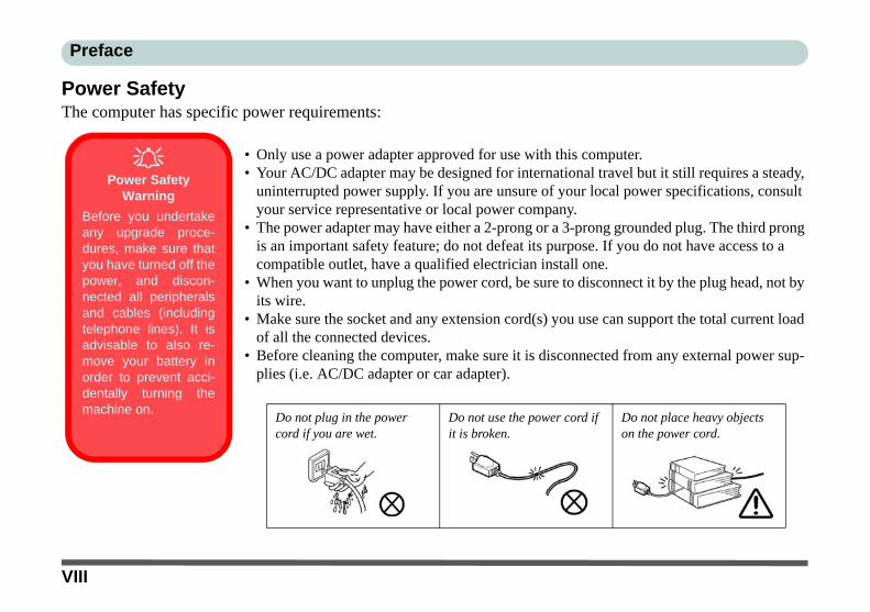
Power SafetyThe computer has specific power requirements:
• Only use a power adapter approved for use with this computer.• Your AC/DC adapter may be designed for international travel but it still requires a steady,
uninterrupted power supply. If you are unsure of your local power specifications, consult your service representative or local power company.
• The power adapter may have either a 2-prong or a 3-prong grounded plug. The third prong is an important safety feature; do not defeat its purpose. If you do not have access to a compatible outlet, have a qualified electrician install one.
• When you want to unplug the power cord, be sure to disconnect it by the plug head, not by its wire.
• Make sure the socket and any extension cord(s) you use can support the total current load of all the connected devices.
• Before cleaning the computer, make sure it is disconnected from any external power sup-plies (i.e. AC/DC adapter or car adapter).
Do not plug in the power cord if you are wet.
Do not use the power cord if it is broken.
Do not place heavy objects on the power cord.
Power Safety
Warning
Before you undertakeany upgrade proce-dures, make sure thatyou have turned off thepower, and discon-nected all peripheralsand cables (includingtelephone lines). It isadvisable to also re-move your battery inorder to prevent acci-dentally turning themachine on.
VIII

Preface
Battery Precautions• Only use batteries designed for this computer. The wrong battery type may explode, leak or damage the computer.• Do not remove any batteries from the computer while it is powered on.• Do not continue to use a battery that has been dropped, or that appears damaged (e.g. bent or twisted) in any way. Even
if the computer continues to work with a damaged battery in place, it may cause circuit damage, which may possibly result in fire.
• If you do not use the battery for an extended period, then remove the battery from the computer for storage.• Recharge the batteries using the notebook’s system. Incorrect recharging may make the battery explode.• Do not try to repair a battery pack. Refer any battery pack repair or replacement to your service representative or qual-
ified service personnel.• Keep children away from, and promptly dispose of a damaged battery. Always dispose of batteries carefully. Batteries
may explode or leak if exposed to fire, or improperly handled or discarded.• Keep the battery away from metal appliances.• Affix tape to the battery contacts before disposing of the battery.• Do not touch the battery contacts with your hands or metal objects.
Battery Disposal & Caution
The product that you have purchased contains a rechargeable battery. The battery is recyclable. At the end of its useful life,under various state and local laws, it may be illegal to dispose of this battery into the municipal waste stream. Check withyour local solid waste officials for details in your area for recycling options or proper disposal.
Danger of explosion if battery is incorrectly replaced. Replace only with the same or equivalent type recommended by themanufacturer. Discard used battery according to the manufacturer’s instructions.
IX
Preface
CleaningDo not apply cleaner directly to the computer; use a soft clean cloth. Do not use volatile (petroleum distillates) or abrasive cleaners on any part of the computer.
ServicingDo not attempt to service the computer yourself. Doing so may violate your warranty and expose you and thecomputer to electric shock. Refer all servicing to authorized service personnel. Unplug the computer from thepower supply. Then refer servicing to qualified service personnel under any of the following conditions:
• When the power cord or AC/DC adapter is damaged or frayed.• If the computer has been exposed to rain or other liquids.• If the computer does not work normally when you follow the operating instructions.• If the computer has been dropped or damaged (do not touch the poisonous liquid if the LCD panel breaks).• If there is an unusual odor, heat or smoke coming from your computer.
Removal Warning
When removing any cover(s) and screw(s) for the purposes of device upgrade, remember to replace the cover(s) andscrew(s) before turning the computer on.
X

Preface
Travel Considerations
PackingAs you get ready for your trip, run through this list to make sure the system is ready to go:
1. Check that the battery pack and any spares are fully charged.2. Power off the computer and peripherals.3. Close the display panel and make sure it’s latched.4. Disconnect the AC/DC adapter and cables. Stow them in the carrying bag. 5. The AC/DC adapter uses voltages from 100 to 240 volts so you won’t need a second voltage adapter. However,
check with your travel agent to see if you need any socket adapters.6. Put the notebook in its carrying bag and secure it with the bag’s straps.7. If you’re taking any peripherals (e.g. a printer, mouse or digital camera), pack them and those devices’ adapters
and/or cables.8. Anticipate customs - Some jurisdictions may have import restrictions or require proof of ownership for both
hardware and software. Make sure your documents are prepared.
Power Off Before Traveling
Make sure that your notebook is completely powered off before putting it into a travel bag (or any such container). Putting anotebook which is powered on in a travel bag may cause the vent(s)/fan intake(s)/outlet(s) to be blocked. To prevent yourcomputer from overheating make sure nothing blocks the vent(s)/fan intake(s)/outlet(s) while the computer is in use.
XI
Preface
On the RoadIn addition to the general safety and maintenance suggestions in this preface, and Chapter 8: Troubleshooting,keep these points in mind:
Hand-carry the notebook - For security, don’t let it out of your sight. In some areas, computer theft is verycommon. Don’t check it with normal luggage. Baggage handlers may not be sufficiently careful. Avoid knock-ing the computer against hard objects.
Beware of Electromagnetic fields - Devices such as metal detectors & X-ray machines can damage the com-puter, hard disk, floppy disks, and other media. They may also destroy any stored data - Pass your computer anddisks around the devices. Ask security officials to hand-inspect them (you may be asked to turn it on). Note:Some airports also scan luggage with these devices.
Fly safely - Most airlines have regulations about the use of computers and other electronic devices in flight.These restrictions are for your safety, follow them. If you stow the notebook in an overhead compartment, makesure it’s secure. Contents may shift and/or fall out when the compartment is opened.
Get power where you can - If an electrical outlet is available, use the AC/DC adapter and keep your battery(ies)charged.
Keep it dry - If you move quickly from a cold to a warm location, water vapor can condense inside the computer.Wait a few minutes before turning it on so that any moisture can evaporate.
XII
Preface
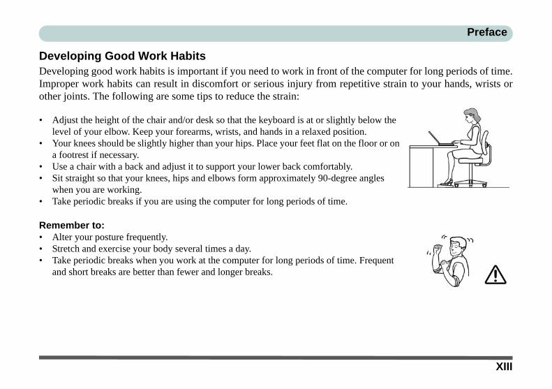
Developing Good Work HabitsDeveloping good work habits is important if you need to work in front of the computer for long periods of time.Improper work habits can result in discomfort or serious injury from repetitive strain to your hands, wrists orother joints. The following are some tips to reduce the strain:
• Adjust the height of the chair and/or desk so that the keyboard is at or slightly below the level of your elbow. Keep your forearms, wrists, and hands in a relaxed position.
• Your knees should be slightly higher than your hips. Place your feet flat on the floor or on a footrest if necessary.
• Use a chair with a back and adjust it to support your lower back comfortably.• Sit straight so that your knees, hips and elbows form approximately 90-degree angles
when you are working.• Take periodic breaks if you are using the computer for long periods of time.
Remember to:• Alter your posture frequently.• Stretch and exercise your body several times a day.• Take periodic breaks when you work at the computer for long periods of time. Frequent
and short breaks are better than fewer and longer breaks.
XIII

Preface
LightingProper lighting and comfortable display viewing angle can reduce eye strain and muscle fatigue in your neck andshoulders.
• Position the display to avoid glare or reflections from overhead lighting or outside sources of light.• Keep the display screen clean and set the brightness and contrast to levels that allow you to see the screen clearly.• Position the display directly in front of you at a comfortable viewing distance.• Adjust the display-viewing angle to find the best position.
LCD Screen CareTo prevent image persistence on LCD monitors (caused by the continuous display of graphics on the screen foran extended period of time) take the following precautions:
• Set the Windows Power Plans to turn the screen off after a few minutes of screen idle time.• Use a rotating, moving or blank screen saver (this prevents an image from being displayed too long).• Rotate desktop background images every few days.• Turn the monitor off when the system is not in use.
XIV

Preface
ContentsNotice ................................................................................. IFCC Statement ................................................................ IIIFCC RF Radiation Exposure Statement: ........................ IVInstructions for Care and Operation ...............................VIPower Safety ................................................................ VIIIBattery Precautions ......................................................... IXCleaning ........................................................................... XServicing .......................................................................... XTravel Considerations .....................................................XI
Quick Start GuideOverview ........................................................................1-1Advanced Users .............................................................1-2Beginners and Not-So-Advanced Users ........................1-2Warning Boxes ..............................................................1-2Not Included ..................................................................1-3System Software ............................................................1-4Model Differences .........................................................1-4System Startup ...............................................................1-5System Map: LCD Panel Open ......................................1-6Keyboard ........................................................................1-7Function/Hot Key Indicators .........................................1-8System Map: Front & Rear Views .................................1-9
LED Indicators ...............................................................1-9System Map: Left View ...............................................1-10System Map: Right View .............................................1-11System Map: Bottom View ..........................................1-123.75G/HSPA Module USIM Card Installation ............1-13Windows 7 Start Menu & Control Panel .....................1-14Video Features .............................................................1-15Screen Resolution & Intel GMA Control Panel ..........1-16Power Options ..............................................................1-17MOFA LCD Back Covers ...........................................1-18
Features & ComponentsOverview ........................................................................2-1Hard Disk Drive .............................................................2-2External USB Optical (CD/DVD) Device .....................2-3Loading Discs ................................................................2-3Handling CDs or DVDs .................................................2-4DVD Regional Codes ....................................................2-53-in-1 Card Reader .........................................................2-6TouchPad and Buttons/Mouse .......................................2-7Finger Sensing Pad Configurator ...................................2-8Gestures .........................................................................2-9Audio Features .............................................................2-10
XV

Preface
Adding a Printer ...........................................................2-12USB Printer ..................................................................2-12Parallel Printer .............................................................2-12
Power ManagementOverview ........................................................................3-1The Power Sources ........................................................3-2AC/DC Adapter .............................................................3-2Battery ............................................................................3-2Turning On the Computer ..............................................3-3Power Plans ...................................................................3-4Power-Saving States ......................................................3-6Sleep ..............................................................................3-6Hibernate ........................................................................3-7Shut down ......................................................................3-7Configuring the Power Buttons .....................................3-8Resuming Operation ......................................................3-9Energy Star Power Saving ...........................................3-10Battery Information .....................................................3-11Battery Power ..............................................................3-11Conserving Battery Power ...........................................3-12Battery Life ..................................................................3-13New Battery .................................................................3-13Recharging the Battery with the AC/DC Adapter .......3-13Proper handling of the Battery Pack ............................3-14
Battery FAQ .................................................................3-15
Drivers & UtilitiesWhat to Install ................................................................4-1Module Driver Installation .............................................4-1Driver Installation ..........................................................4-2Updating/Reinstalling Individual Drivers ......................4-4User Account Control ....................................................4-4Windows Security Message ...........................................4-4New Hardware Found ....................................................4-5Driver Installation Procedure .........................................4-5Chipset ...........................................................................4-5Video (VGA) .................................................................4-5LAN ...............................................................................4-5Card Reader ...................................................................4-6TouchPad .......................................................................4-6Hot Key ..........................................................................4-6Audio .............................................................................4-6Windows Experience Index ...........................................4-7Optional Drivers ............................................................4-8Wireless LAN Module ...................................................4-8PC Camera Module ........................................................4-83.75G/HSPA Module .....................................................4-8Bluetooth Module ..........................................................4-8
XVI
Preface
BIOS UtilitiesOverview ........................................................................5-1The Power-On Self Test (POST) ...................................5-2Failing the POST ...........................................................5-3Fatal Errors ....................................................................5-3Non-Fatal Errors ............................................................5-3The Setup Utility ............................................................5-4Entering Setup ...............................................................5-4Setup Screens .................................................................5-5Main Menu .....................................................................5-6System Time & Date (Main Menu) ...............................5-6SATA Port 1 (Main Menu) ............................................5-7System/Extended Memory (Main Menu) ......................5-7Advanced Menu .............................................................5-8Detect External CRT (Advanced Menu > Advanced Chipset Control) ...........5-8SATA Mode Selection (Advanced Menu) ....................5-9Legacy USB Support (Advanced Menu) .......................5-9Boot-time Diagnostic Screen (Advanced Menu) ...........5-9Power On Boot Beep (Advanced Menu) .......................5-9Battery Low Alarm Beep (Advanced Menu) .................5-9Security Menu ..............................................................5-10Set Supervisor Password (Security Menu) ..................5-10Set User Password (Security Menu) ............................5-11Password on boot (Security Menu) ..............................5-11
Boot Menu ...................................................................5-12Exit Menu ....................................................................5-13
Upgrading The ComputerOverview ........................................................................6-1When Not to Upgrade ....................................................6-2Removing the Battery ....................................................6-3Upgrading the System Memory (RAM) ........................6-4Changing the Optional LCD Back Covers ....................6-7Upgrading the Hard Disk .............................................6-10
Modules & OptionsOverview ........................................................................7-1Wireless LAN Module ...................................................7-2802.11b/g/n WLAN Driver Installation .........................7-3Connecting to a Wireless Network ................................7-4Windows Mobility Center .............................................D-7PC Camera Module ........................................................7-8PC Camera Driver Installation .......................................7-93.75G/HSPA Module ...................................................7-15Mobile Partner .............................................................7-17Mobile Partner Application Installation ......................7-17Mobile Partner Application .........................................7-18Profile Management .....................................................7-18Text Messaging Service ...............................................7-23
XVII
Preface
Bluetooth Module ........................................................7-24Bluetooth Configuration in Windows 7 .......................7-25
TroubleshootingOverview ........................................................................8-1Basic Hints and Tips ......................................................8-2Backup and General Maintenance .................................8-3Viruses ...........................................................................8-4Upgrading and Adding New Hardware/Software ..........8-5Problems and Possible Solutions ...................................8-7Bluetooth Connection Problems ..................................8-13
Interface (Ports & Jacks)Notebook Ports and Jacks ............................................. A-2
Intel Video Driver ControlsIntel Video Driver Installation ...................................... B-1Video ............................................................................. B-1Dynamic Video Memory Technology .......................... B-1Intel GMA Driver for Mobile ....................................... B-2Scheme Options ............................................................ B-4Display Devices & Options .......................................... B-5Attaching Other Displays ............................................. B-6Attaching Other Displays ............................................. B-8
SpecificationsProcessor ....................................................................... C-2Core Logic .................................................................... C-2Display .......................................................................... C-2Memory ......................................................................... C-2Video Adapter ............................................................... C-2BIOS ............................................................................. C-2Storage .......................................................................... C-2Security ......................................................................... C-2Audio ............................................................................ C-2Pointing Device ............................................................. C-2Keyboard ....................................................................... C-2Interface ........................................................................ C-2Communication ............................................................. C-3Operating System .......................................................... C-3Card Reader .................................................................. C-3Slot ................................................................................ C-3Power Management ...................................................... C-3Power ............................................................................ C-3Design Feature .............................................................. C-3Battery ........................................................................... C-3Environmental Spec ...................................................... C-3Dimensions & Weight .................................................. C-3
XVIII
Quick Start Guide 1
Chapter 1: Quick Start Guide
OverviewThis Quick Start Guide is a brief introduction to the basic features of your computer, to navigating around thecomputer and to getting your system started. The remainder of the manual covers the following:
• Chapter 2 A guide to using some of the main features of the computer e.g. the storage devices (hard disk, optical device, card reader), TouchPad & Mouse, Audio & Printer.
• Chapter 3 The computer’s power saving options.• Chapter 4 The installation of the drivers and utilities essential to the operation or improvement of some of the
computer’s subsystems.• Chapter 5 An outline of the computer’s built-in software or BIOS (Basic Input Output System).• Chapter 6 Instructions for upgrading your computer.• Chapter 7 A quick guide to the computer’s Wireless LAN, PC Camera, 3.75G/HSPA and Bluetooth mod-
ules (some of which may be optional depending on your purchase configuration).• Chapter 8 A troubleshooting guide.• Appendix A Definitions of the interface, ports/jacks which allow your computer to communicate with external
devices.• Appendix B Information on the Intel Video driver controls.• Appendix C The computer’s specification.
Overview 1 - 1
Quick Start Guide1
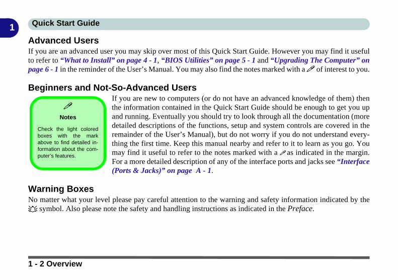
Advanced UsersIf you are an advanced user you may skip over most of this Quick Start Guide. However you may find it usefulto refer to “What to Install” on page 4 - 1, “BIOS Utilities” on page 5 - 1 and “Upgrading The Computer” onpage 6 - 1 in the reminder of the User’s Manual. You may also find the notes marked with a of interest to you.Beginners and Not-So-Advanced UsersIf you are new to computers (or do not have an advanced knowledge of them) thenthe information contained in the Quick Start Guide should be enough to get you upand running. Eventually you should try to look through all the documentation (moredetailed descriptions of the functions, setup and system controls are covered in theremainder of the User’s Manual), but do not worry if you do not understand every-thing the first time. Keep this manual nearby and refer to it to learn as you go. Youmay find it useful to refer to the notes marked with a as indicated in the margin.For a more detailed description of any of the interface ports and jacks see “Interface(Ports & Jacks)” on page A - 1.
Warning BoxesNo matter what your level please pay careful attention to the warning and safety information indicated by the symbol. Also please note the safety and handling instructions as indicated in the Preface.
Notes
Check the light coloredboxes with the markabove to find detailed in-formation about the com-puter’s features.
1 - 2 Overview

Quick Start Guide 1
Not IncludedOperating Systems (e.g. Windows 7) and applications (e.g. word processing, spreadsheet and database programs)have their own manuals, so please consult the appropriate manuals.Drivers
If you are installing new system software, or are re-configuring your computer for a different system, you will need to installthe drivers listed in “Drivers & Utilities” on page 4 - 1. Drivers are programs which act as an interface between the com-puter and a hardware component e.g. a wireless network module. It is very important that you install the drivers in the orderlisted. You will be unable to use most advanced controls until the necessary drivers and utilities are properly installed. Ifyour system hasn’t been properly configured (your service representative may have already done that for you); refer toChapter 4 for installation instructions.
You will need to attach an optical device drive to the computer in order to access the drivers on the Device Drivers &Utilities + User’s Manual disc. This contains the drivers and utilities necessary for the proper operation of the computer.
Ports and Jacks
See “Notebook Ports and Jacks” on page A - 2 for a description of the interface (ports & jacks) which allow your com-puter to communicate with external devices, connect to the internet etc.
Overview 1 - 3
Quick Start Guide1
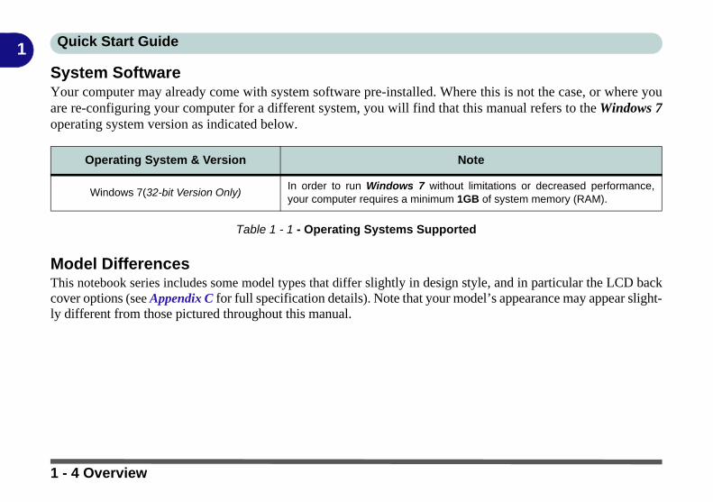
System SoftwareYour computer may already come with system software pre-installed. Where this is not the case, or where youare re-configuring your computer for a different system, you will find that this manual refers to the Windows 7operating system version as indicated below.Table 1 - 1 - Operating Systems Supported
Model DifferencesThis notebook series includes some model types that differ slightly in design style, and in particular the LCD backcover options (see Appendix C for full specification details). Note that your model’s appearance may appear slight-ly different from those pictured throughout this manual.
Operating System & Version Note
Windows 7(32-bit Version Only)In order to run Windows 7 without limitations or decreased performance,your computer requires a minimum 1GB of system memory (RAM).
1 - 4 Overview
Quick Start Guide 1
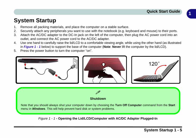
System Startup1. Remove all packing materials, and place the computer on a stable surface.2. Securely attach any peripherals you want to use with the notebook (e.g. keyboard and mouse) to their ports.3. Attach the AC/DC adapter to the DC-In jack on the left of the computer, then plug the AC power cord into an
outlet, and connect the AC power cord to the AC/DC adapter.4. Use one hand to carefully raise the lid/LCD to a comfortable viewing angle, while using the other hand (as illustrated
in Figure 1 - 1 below) to support the base of the computer (Note: Never lift the computer by the lid/LCD).5. Press the power button to turn the computer “on”.
Figure 1 - 1 - Opening the Lid/LCD/Computer with AC/DC Adapter Plugged-In
Shutdown
Note that you should always shut your computer down by choosing the Turn Off Computer command from the Startmenu in Windows. This will help prevent hard disk or system problems.
System Startup 1 - 5
Quick Start Guide1
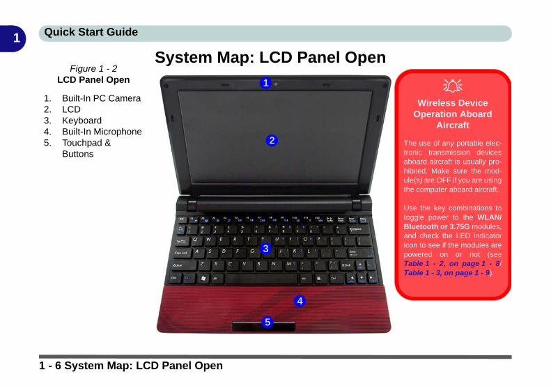
System Map: LCD Panel OpenFigure 1 - 2
LCD Panel Open
1. Built-In PC Camera 2. LCD3. Keyboard4. Built-In Microphone5. Touchpad &
Buttons
2
1
5
3
Wireless Device
Operation Aboard Aircraft
The use of any portable elec-tronic transmission devicesaboard aircraft is usually pro-hibited. Make sure the mod-ule(s) are OFF if you are usingthe computer aboard aircraft.
Use the key combinations totoggle power to the WLAN/Bluetooth or 3.75G modules,and check the LED indicatoricon to see if the modules arepowered on or not (seeTable 1 - 2, on page 1 - 8/Table 1 - 3, on page 1 - 9).
4
1 - 6 System Map: LCD Panel Open
Quick Start Guide 1
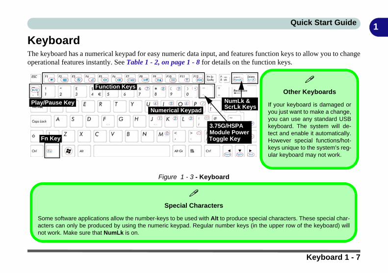
KeyboardThe keyboard has a numerical keypad for easy numeric data input, and features function keys to allow you to changeoperational features instantly. See Table 1 - 2, on page 1 - 8 for details on the function keys.
Figure 1 - 3 - Keyboard
Other Keyboards
If your keyboard is damaged oryou just want to make a change,you can use any standard USBkeyboard. The system will de-tect and enable it automatically.However special functions/hot-keys unique to the system’s reg-ular keyboard may not work.
Play/Pause Key
Function Keys
NumLk & ScrLk Keys
Toggle Key
3.75G/HSPA Module Power
Fn Key
Numerical Keypad
Special Characters
Some software applications allow the number-keys to be used with Alt to produce special characters. These special char-acters can only be produced by using the numeric keypad. Regular number keys (in the upper row of the keyboard) willnot work. Make sure that NumLk is on.
Keyboard 1 - 7
Quick Start Guide1
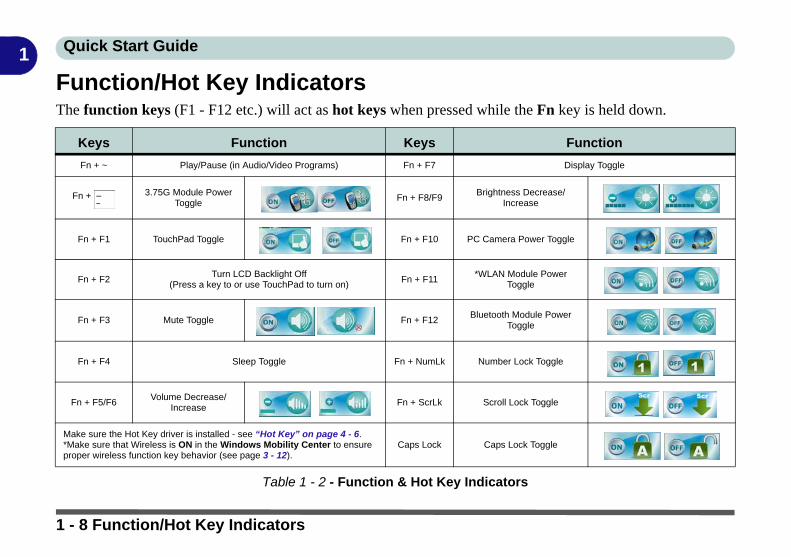
Function/Hot Key IndicatorsThe function keys (F1 - F12 etc.) will act as hot keys when pressed while the Fn key is held down.
Table 1 - 2 - Function & Hot Key Indicators
Keys Function Keys Function
Fn + ~ Play/Pause (in Audio/Video Programs) Fn + F7 Display Toggle
Fn + 3.75G Module Power Toggle
Fn + F8/F9Brightness Decrease/
Increase
Fn + F1 TouchPad Toggle Fn + F10 PC Camera Power Toggle
Fn + F2Turn LCD Backlight Off
(Press a key to or use TouchPad to turn on)Fn + F11
*WLAN Module Power Toggle
Fn + F3 Mute Toggle Fn + F12Bluetooth Module Power
Toggle
Fn + F4 Sleep Toggle Fn + NumLk Number Lock Toggle
Fn + F5/F6Volume Decrease/
Increase Fn + ScrLk Scroll Lock Toggle
Make sure the Hot Key driver is installed - see “Hot Key” on page 4 - 6.*Make sure that Wireless is ON in the Windows Mobility Center to ensure proper wireless function key behavior (see page 3 - 12).
Caps Lock Caps Lock Toggle
1 - 8 Function/Hot Key Indicators

Quick Start Guide 1
System Map: Front & Rear Views
LED Indicators
Icon Color Description
Orange DC Power is Plugged In
Green The Computer is On
Blinking Green The Computer is in Sleep Mode
Orange The Battery is Charging
Green The Battery is Fully Charged
Blinking Orange The Battery Has Reached Critically Low Power Status
Green Hard Disk Activity
Green The (optional) Wireless LAN Module is Powered On
Orange The (optional) Bluetooth Module is Powered On
Figure 1 - 4Front & Rear Views
1. LED Indicators2. Battery
Table 1 - 3
LED Indicators
1
2
System Map: Front & Rear Views 1 - 9

Quick Start Guide1
System Map: Left ViewFigure 1 - 5Left View
1. Security Lock Slot2. DC-In Jack3. Vent/Fan Intake/
Outlet4. USB 2.0 Port5. Microphone-In Jack6. Headphone-Out
Jack
1 354 6
External Optical (CD/DVD) Device Drives
To install applications and drivers etc. you willneed to attach an external optical CD/DVD deviceto the USB ports.
Overheating
To prevent your computer fromoverheating make sure nothingblocks the vent(s)/fan intake(s)while the computer is in use.
2
1 - 10 System Map: Left View
Quick Start Guide 1
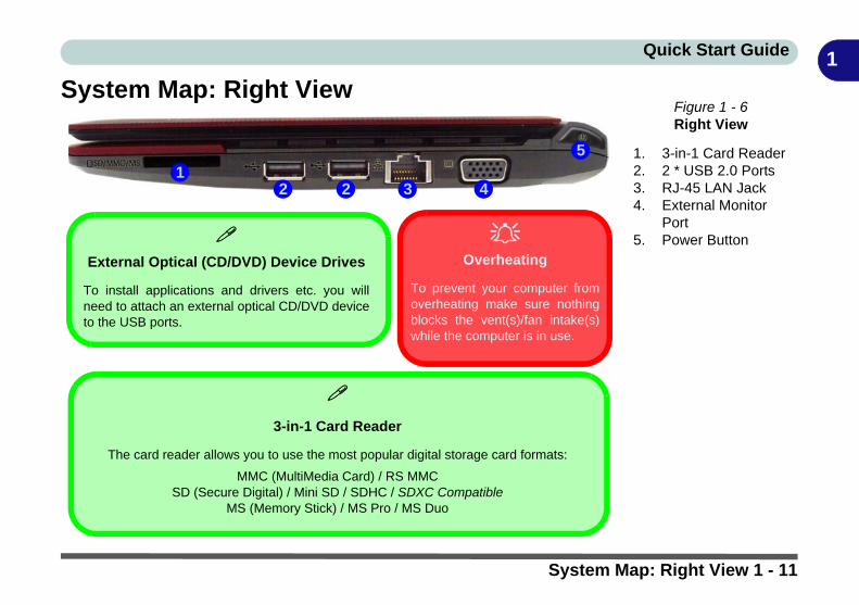
System Map: Right ViewFigure 1 - 6Right View
1. 3-in-1 Card Reader2. 2 * USB 2.0 Ports3. RJ-45 LAN Jack4. External Monitor
Port5. Power Button
12 3
5
4
External Optical (CD/DVD) Device Drives
To install applications and drivers etc. you willneed to attach an external optical CD/DVD deviceto the USB ports.
Overheating
To prevent your computer fromoverheating make sure nothingblocks the vent(s)/fan intake(s)while the computer is in use.
3-in-1 Card Reader
The card reader allows you to use the most popular digital storage card formats:
MMC (MultiMedia Card) / RS MMCSD (Secure Digital) / Mini SD / SDHC / SDXC Compatible
MS (Memory Stick) / MS Pro / MS Duo
2
System Map: Right View 1 - 11
Quick Start Guide1
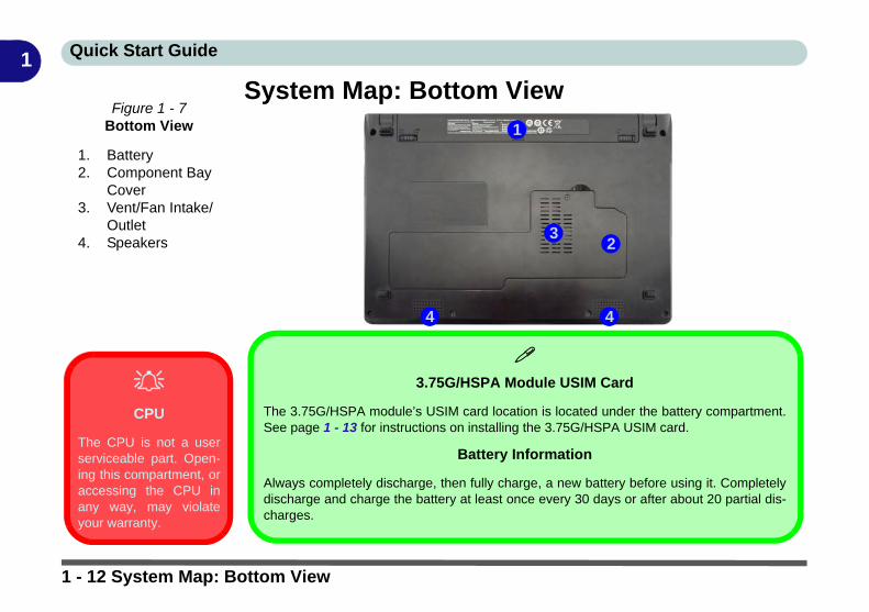
System Map: Bottom View Figure 1 - 7
Bottom View
1. Battery2. Component Bay
Cover3. Vent/Fan Intake/
Outlet4. Speakers
CPU
The CPU is not a userserviceable part. Open-ing this compartment, oraccessing the CPU inany way, may violateyour warranty.
1
32
4
3.75G/HSPA Module USIM Card
The 3.75G/HSPA module’s USIM card location is located under the battery compartment.See page 1 - 13 for instructions on installing the 3.75G/HSPA USIM card.
Battery Information
Always completely discharge, then fully charge, a new battery before using it. Completelydischarge and charge the battery at least once every 30 days or after about 20 partial dis-charges.
4
1 - 12 System Map: Bottom View

Quick Start Guide 1
3.75G/HSPA Module USIM Card InstallationIf you have included an optional 3.75G/HSPA module in your purchase option, follow the instructions below toinstall the USIM card (which will be provided by your service provider), and then run the Mobile Partner ap-plication. See “Mobile Partner” on page 7 - 17 for instructions on installing the program etc.
1. Turn off the computer, and turn it over and then remove the battery (slide the latches in the direction indicated below and slide the battery out).
2. Insert the USIM card as illustrated below until it clicks fully into position, and replace the battery.
Figure 1 - 8 - Battery Removal & USIM Card Insertion
USIM Card Orientation
Note that the USIMcard’s readable side(with the gold-coloredcontacts) should faceupwards as illustrated.
3.75G/HSPA Module USIM Card Installation 1 - 13
Quick Start Guide1
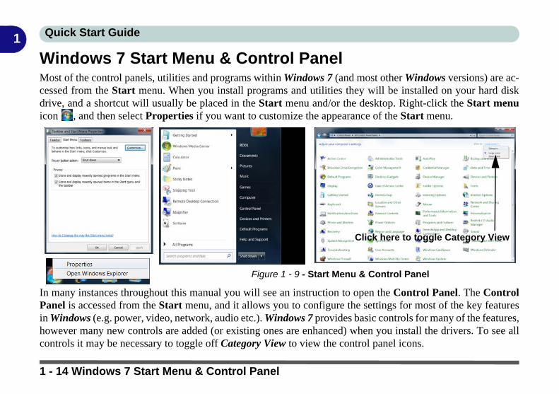
Windows 7 Start Menu & Control PanelMost of the control panels, utilities and programs within Windows 7 (and most other Windows versions) are ac-cessed from the Start menu. When you install programs and utilities they will be installed on your hard diskdrive, and a shortcut will usually be placed in the Start menu and/or the desktop. Right-click the Start menuicon , and then select Properties if you want to customize the appearance of the Start menu.
In many instances throughout this manual you will see an instruction to open the Control Panel. The ControlPanel is accessed from the Start menu, and it allows you to configure the settings for most of the key featuresin Windows (e.g. power, video, network, audio etc.). Windows 7 provides basic controls for many of the features,however many new controls are added (or existing ones are enhanced) when you install the drivers. To see allcontrols it may be necessary to toggle off Category View to view the control panel icons.
Figure 1 - 9 - Start Menu & Control Panel
Click here to toggle Category View
1 - 14 Windows 7 Start Menu & Control Panel

Quick Start Guide 1
Video FeaturesYou can configure display options from the Display (Control Panel) and Screen Resolution in Windows. Formore detailed video information see Chapter B“Intel Video Driver Controls” from page B - 1.
To access Display (Control Panel) and Screen Resolution in Windows:1. Click Start and click Control Panel.2. Click Display (icon) - In the Appearances and Personalization category.3. Click Adjust Screen Resolution/Adjust resolution.OR4. Alternatively you can right-click the desktop and select Screen resolution (see right).5. Use the dropbox to select the screen Resolution (Figure 1 - 10 on page 1 - 16).6. Click Advanced settings (Figure 1 - 10 on page 1 - 16) to bring up the Advanced
properties tabs.
To access the Intel(R) Graphics Media Accelerator Driver for mobile control panel:1. Click Advanced settings (Figure 1 - 10 on page 1 - 16) in the Screen Resolution
control panel in Windows.2. Click the Intel(R)... tab (Figure 1 - 10 on page 1 - 16) and click Graphics Properties (button).OR3. Right-click the desktop and select Graphics Properties from the menu.OR4. Click the icon in the taskbar and select Graphics Properties from the menu.
12
2
3
Video Features 1 - 15

Quick Start Guide1
Screen Resolution & Intel GMA Control PanelFigure 1 - 10 - Screen Resolution & Intel GMA Driver for Mobile Control Panel
1
2 3
4
1 - 16 Video Features

Quick Start Guide 1
Power OptionsThe Power Options (Hardware and Sound menu) control panel icon in Windows (see page 1 - 14) allows youto configure power management features for your computer. You can conserve power by means of power plansand configure the options for the power button, sleep button, computer lid (when closed), display and sleepmode from the left menu. Note that the Power saver plan may have an affect on computer performance.
Click to select one of the existing plans, or click Create a power plan in the left menu and select the options tocreate a new plan. Click Change plan settings and click Change advanced power settings to access further con-figuration options.
Pay attention to the instructions on battery care in “Battery Information” on page 3 - 11.
Figure 1 - 11 - Power Options
Power Options 1 - 17

Quick Start Guide1
MOFA LCD Back CoversMOFA (Magic of Film Art) technology allows fashionable and unique pictorial designs to be printed on the spe-cially designed changeable LCD back covers. If your purchase option includes the specially designed change-able LCD back cover option, then follow the instructions in “Changing the Optional LCD Back Covers” onpage 6 - 12 to change the covers (note these covers are not applicable to all models in this series - consultyour service center for details).
Figure 1 - 12 - Magic Of Film Art Optional LCD Back Covers
1 - 18 MOFA LCD Back Covers
Features & Components
2
Chapter 2: Features & ComponentsOverviewRead this chapter to learn more about the following main features and componentsof the computer:
• Hard Disk Drive• External USB Optical (CD/DVD) Device• 3-in-1 Card Reader• TouchPad and Buttons/Mouse• Audio Features• Adding a Printer
Overview 2 - 1
Features & Components
2
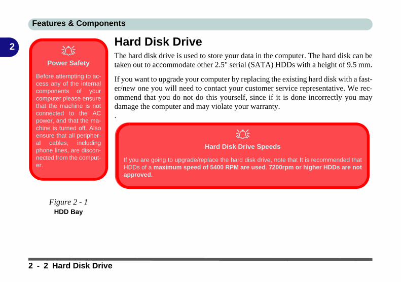
Hard Disk DriveThe hard disk drive is used to store your data in the computer. The hard disk can betaken out to accommodate other 2.5" serial (SATA) HDDs with a height of 9.5 mm.If you want to upgrade your computer by replacing the existing hard disk with a fast-er/new one you will need to contact your customer service representative. We rec-ommend that you do not do this yourself, since if it is done incorrectly you maydamage the computer and may violate your warranty..
Power Safety
Before attempting to ac-cess any of the internalcomponents of yourcomputer please ensurethat the machine is notconnected to the ACpower, and that the ma-chine is turned off. Alsoensure that all peripher-al cables, includingphone lines, are discon-nected from the comput-er.
Figure 2 - 1HDD Bay
Hard Disk Drive Speeds
If you are going to upgrade/replace the hard disk drive, note that It is recommended thatHDDs of a maximum speed of 5400 RPM are used. 7200rpm or higher HDDs are notapproved.
2 - 2 Hard Disk Drive

Features & Components
2
External USB Optical (CD/DVD) DeviceAn external USB optical (CD/DVD) device is available as an option for this com-puter. The optical device may be used as a boot device if properly set in the BIOS(see “Boot Menu” on page 5 - 12).Loading DiscsTo insert a CD/DVD, simply slide the disc into the disc slot with label-side facingup. The busy indicator will light up while data is being accessed, or while a disc isplaying. If power is unexpectedly interrupted, insert an object such as a straightenedpaper clip into the emergency eject hole to eject the disc.
USB Cables
You can connect the op-tional USB optical de-vice using one of theUSB cables. However ifyou are experiencingconnection or powerproblems, connect bothUSB cables from the de-vice to the computer.
External Optical (CD/DVD) Device
Drives
To install applicationsand drivers etc. you willneed to attach an exter-nal optical CD/DVD de-vice to the USB ports.
External USB Optical (CD/DVD) Device 2 - 3

Features & Components
2
Handling CDs or DVDsProper handling of your CDs/DVDs will prevent them from being damaged. Pleasefollow the advice below to make sure that the data stored on your CDs/DVDs can beaccessed.Note the following:
• Hold the CD or DVD by the edges; do not touch the surface of the disc.• Use a clean, soft, dry cloth to remove dust or fingerprints.• Do not write on the surface with a pen.• Do not attach paper or other materials to the surface of the disc.• Do not store or place the CD or DVD in high-temperature areas.• Do not use benzene, thinner, or other cleaners to clean the CD or DVD.• Do not bend the CD or DVD.• Do not drop or subject the CD or DVD to shock.
CD Emergency Eject
If you need to manuallyeject a CD (e.g. due toan unexpected powerinterruption) you maypush the end of astraightened paper clipinto the emergency ejecthole. However pleasedo NOT use a sharp-ened pencil or similarobject that may breakand become lodged inthe hole.
Disk Eject Warning
Don’t try to remove aCD/DVD while the sys-tem is accessing it. Thismay cause the systemto “crash”.
2 - 4 External USB Optical (CD/DVD) Device

Features & Components
2
DVD Regional CodesGo to the Control Panel and double-click Device Manager (Hardware andSound), then click the + next to DVD/CD-ROM drives. Double-click on the DVD-ROM device to bring up the Properties dialog box, and select the DVD Region(tab) to bring up the control panel to allow you to adjust the regional code.DVD region detection is device dependent, not OS-dependent. You can select yourmodule’s region code 5 times. The fifth selection is permanent. This cannot be al-tered even if you change your operating system or you use the module in anothercomputer.
DVD Regional Coding
Region Geographical Location
1 USA, Canada
2 Western Europe, Japan, South Africa, Middle East & Egypt
3South-East Asia, Taiwan, South Korea, The Philippines,
Indonesia, Hong Kong
4 South & Central America, Mexico, Australia, New Zealand
5 N Korea, Russia, Eastern Europe, India & Most of Africa
6 China
Table 2 - 1DVD Regional Coding
External USB Optical (CD/DVD) Device 2 - 5

Features & Components
2
3-in-1 Card ReaderThe card reader allows you to use some of the latest digital storage cards. Push thecard into the slot and it will appear as a removable device, and can be accessed inthe same way as your hard disk (s). Make sure you install the card reader driver (see“Card Reader” on page 4 - 6).Note: Some of these cards require PC adapters that are usually supplied with thecards.
Card Reader Cover
Make sure you keep therubber cover provided inthe card reader whennot in use. This will helpprevent foreign objectsand/or dust getting in tothe card reader.
Figure 2 - 2Right View
1. Card Reader
• MMC (MultiMedia Card) / RS MMC• SD (Secure Digital) / Mini SD / SDHC / SDXC Compatible• MS (Memory Stick) / MS Pro / MS Duo
1
2 - 6 3-in-1 Card Reader
Features & Components
2
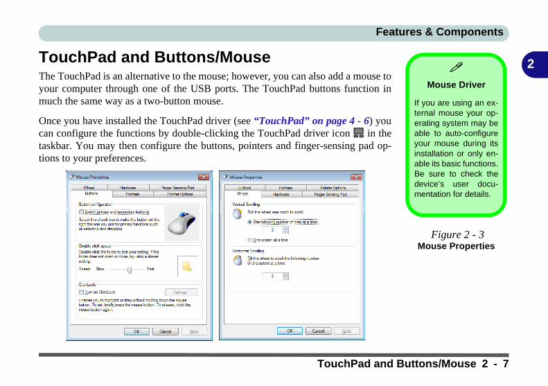
TouchPad and Buttons/MouseThe TouchPad is an alternative to the mouse; however, you can also add a mouse toyour computer through one of the USB ports. The TouchPad buttons function inmuch the same way as a two-button mouse.Once you have installed the TouchPad driver (see “TouchPad” on page 4 - 6) youcan configure the functions by double-clicking the TouchPad driver icon in thetaskbar. You may then configure the buttons, pointers and finger-sensing pad op-tions to your preferences.
Mouse Driver
If you are using an ex-ternal mouse your op-erating system may beable to auto-configureyour mouse during itsinstallation or only en-able its basic functions.Be sure to check thedevice’s user docu-mentation for details.
Figure 2 - 3Mouse Properties
TouchPad and Buttons/Mouse 2 - 7

Features & Components
2
Finger Sensing Pad ConfiguratorThe Finger Sensing Pad Configurator allows you to use a configure the settingsfor the Finger Pad device and software. The left pane in the control panel containsall the configurable items, and you can click the “+” to expand the menu selections.You can configure the settings from the Device Settings tab in Mouse Properties:
1. Click Start, and click Control Panel (or point to Settings and click Control Panel).2. Click Mouse (Hardware and Sound).3. Click Finger Sensing Pad (tab) and click Configure.4. Use the menu tree on the left to access the user configurable settings.
Figure 2 - 4Finger Sensing
Pad
2 - 8 TouchPad and Buttons/Mouse

Features & Components
2
GesturesClick Gestures and make sure that the Enable Gestures tickbox is clicked. Double-click Gestures and then double-click Advanced to open the submenu. You can con-figure any of the gestures from this submenu.Play Video
You can get a clearerview of the gestures in-volved by clicking thePlay Video option foreach gesture item.
Figure 2 - 5Finger Sensing Pad - Gestures
(Advanced)
TouchPad and Buttons/Mouse 2 - 9

Features & Components
2
Audio FeaturesYou can configure the audio options on your computer from the Sound controlpanel in Windows, from the HD VDeck icon on the desktop or VIA HD AudioDeck control panel .The volume may also be adjusted by means of the Fn + F5/F6 key combination.
Sound Volume
Adjustment
The sound volume levelis set using the volumecontrol within Windows(and the volume func-tion keys on the comput-er). Click the volumeicon in the taskbar tocheck the setting.
Figure 2 - 6VIA HD Audio Deck
Click Expert Mode to access the Advanced menus
2 - 10 Audio Features
Features & Components
2
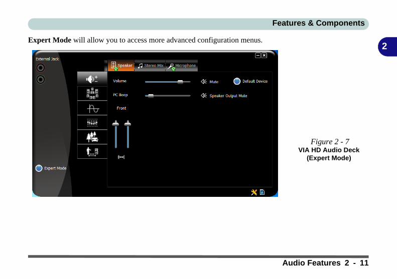
Expert Mode will allow you to access more advanced configuration menus.Figure 2 - 7VIA HD Audio Deck
(Expert Mode)
Audio Features 2 - 11

Features & Components
2
Adding a PrinterThe most commonly used peripheral is a printer. The following conventions willhelp you to add a printer; however it is always best to refer to the printer manual forspecific instructions and configuration options.USB PrinterMost current printers have a USB interface connection. You may use any one of theports to connect the printer.
Install Instructions:1. Set up the printer according to its instructions (unpacking, paper tray, toner/ink car-
tridge etc.).2. Turn ON the computer.3. Turn ON the printer.4. Connect the printer’s USB cable to one of the USB ports on the computer.5. Windows will identify the printer and either load one of its own drivers or ask you
to supply one. Follow the on-screen instructions.
Parallel PrinterThis is still a very common type of printer. The install instructions are in the sidebar,however you will need to purchase a parallel to USB converter.
Parallel Printer
After setting up the print-er attach the parallel ca-ble to the printer.
Connect the printer’sparallel cable to the Par-allel to USB converter,and then plug the con-verter into the USB port.
Turn ON the printer,then turn ON the com-puter.
Windows will identify theprinter and either loadone of its own drivers orask you to supply one.Follow the on-screen in-structions.
2 - 12 Adding a Printer

Power Management
3
Chapter 3: Power Management
OverviewTo conserve power, especially when using the battery, your computer power man-agement conserves power by controlling individual components of the computer(the monitor and hard disk drive) or the whole system. This chapter covers:
• The Power Sources• Turning On the Computer• Power Plans• Power-Saving States• Configuring the Power Buttons• Energy Star Power Saving• Battery Information
The computer uses enhanced power saving techniques to give the operating system(OS) direct control over the power and thermal states of devices and processors. Forexample, this enables the OS to set devices into low-power states based on user set-tings and information from applications.
OS Note
Power managementfunctions will vary slight-ly depending on youroperating system. Formore information it isbest to refer to the user’smanual of your operat-ing system.
Overview 3 - 1

Power Management
3
The Power SourcesThe computer can be powered by either an AC/DC adapter or a battery pack.
AC/DC AdapterUse only the AC/DC adapter that comes with your computer. The wrong type of AC/DC adapter will damage the computer and its components.
1. Attach the AC/DC adapter to the DC-in jack on the left of the computer.2. Plug the AC power cord into an outlet, and then connect the AC power cord to the
AC/DC adapter.3. Raise the lid/LCD to a comfortable viewing angle.4. Press the power button to turn “On”.
BatteryThe battery allows you to use your computer while you are on the road or when anelectrical outlet is unavailable. Battery life varies depending on the applications andthe configuration you're using. To increase battery life, let the battery dischargecompletely before recharging (see “How do I completely discharge the battery?”on page 3 - 15).
We recommend that you do not remove the battery. For more information on the bat-tery, please refer to “Resuming Operation” on page 3 - 9.
3 - 2 The Power Sources

Power Management
3
Turning On the ComputerNow you are ready to begin using your computer. To turn it on simply press the pow-er button on the front panel.
When the computer is on, you can use the power button as a Stand by/Hibernate/Shutdown hot-key button when it is pressed for less than 4 seconds (pressing andholding the power button for longer than this will shut the computer down). UsePower Options in the Windows control panel to configure this feature.
Forced Off
If the system “hangs”,and the Ctrl + Alt + Delkey combination doesn’twork, press the powerbutton for 4 seconds, orlonger, to force the sys-tem to turn itself off.
Power Button as Stand by or
Hibernate Button
You can use the OS’s“Power Options” controlpanel to set the powerbutton to send the sys-tem into Stand by or Hi-bernate mode (see yourOS’s documentation, or“Configuring the Pow-er Buttons” on page 3- 8 for details).
Shut Down
Note that you should always shut your computer down by choosing the Shut Down com-mand from the bottom right of the Start menu in Windows. This will help prevent hard diskor system problems.
Turning On the Computer 3 - 3
Power Management
3
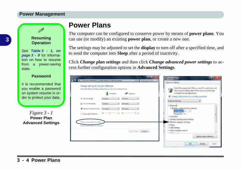
Power PlansThe computer can be configured to conserve power by means of power plans. Youcan use (or modify) an existing power plan, or create a new one.
The settings may be adjusted to set the display to turn off after a specified time, andto send the computer into Sleep after a period of inactivity.
Click Change plan settings and then click Change advanced power settings to ac-cess further configuration options in Advanced Settings.
Resuming Operation
See Table 3 - 1, onpage 3 - 9 for informa-tion on how to resumefrom a power-savingstate.
Password
It is recommended thatyou enable a passwordon system resume in or-der to protect your data.
Figure 3 - 1Power Plan
Advanced Settings
3 - 4 Power Plans
Power Management
3
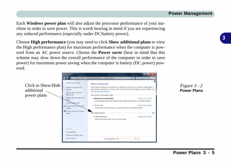
Each Windows power plan will also adjust the processor performance of your ma-chine in order to save power. This is worth bearing in mind if you are experiencingany reduced performance (especially under DC/battery power).
Choose High performance (you may need to click Show additional plans to viewthe High performance plan) for maximum performance when the computer is pow-ered from an AC power source. Choose the Power saver (bear in mind that thisscheme may slow down the overall performance of the computer in order to savepower) for maximum power saving when the computer is battery (DC power) pow-ered.
Figure 3 - 2Power Plans
Click to Show/Hide additional power plans
Power Plans 3 - 5
Power Management
3
Power-Saving StatesYou can use power-saving states to stop the computer’s operation and restart whereyou left off. Win 7 uses the Sleep, Hibernate and Shut Down power-saving states.
SleepIn Sleep all of your work, settings and preferences are saved to memory before thesystem sleeps. When you are not using your computer for a certain length of time,which you specify in the operating system, it will enter Sleep to save power.
The PC wakes from Sleep within seconds and will return you to where you last leftoff (what was on your desktop) without reopening the application(s) and file(s) youlast used.
If your mobile PC in Sleep is running on battery power the system will use only aminimum amount of power. After an extended period the system will save all theinformation to the hard disk and shut the computer down before the battery becomesdepleted.
3 - 6 Power-Saving States
Power Management
3
HibernateHibernate uses the least amount of power of all the power-saving states and savesall of your information on a part of the hard disk before it turns the system off. If apower failure occurs the system can restore your work from the hard disk; if a powerfailure occurs when work is saved only to memory, then the work will be lost. Hi-bernate will also return you to where you last left off within seconds. You shouldput your mobile PC into Hibernate if you will not use the computer for a period oftime, and will not have the chance to charge the battery.
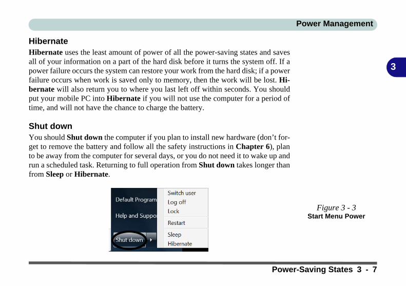
Shut downYou should Shut down the computer if you plan to install new hardware (don’t for-get to remove the battery and follow all the safety instructions in Chapter 6), planto be away from the computer for several days, or you do not need it to wake up andrun a scheduled task. Returning to full operation from Shut down takes longer thanfrom Sleep or Hibernate.
Figure 3 - 3Start Menu Power
Power-Saving States 3 - 7

Power Management
3
Configuring the Power ButtonsThe power/sleep button (Fn + F4 key combo) and closed lid may be set to send thecomputer in to a power-saving state. Click Choose what the power buttons do onthe left menu in Power Options to bring up the menu.
Password Protection
It is recommended thatyou enable a passwordon wake up in order toprotect your data.
However you can dis-able this setting from thePower Options menuby clicking Require apassword on wakeupin the left menu, and se-lecting the options (clickChange settings thatare currently unavail-able).
Figure 3 - 4Power Options Define Power
Buttons
3 - 8 Configuring the Power Buttons
Power Management
3
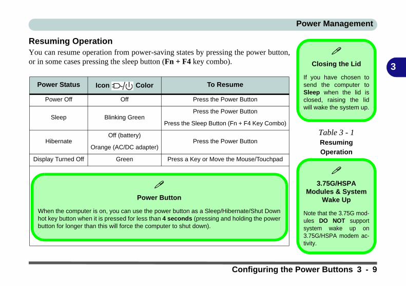
Resuming OperationYou can resume operation from power-saving states by pressing the power button,or in some cases pressing the sleep button (Fn + F4 key combo).
Power Status Icon Color To Resume
Power Off Off Press the Power Button
Sleep Blinking GreenPress the Power Button
Press the Sleep Button (Fn + F4 Key Combo)
HibernateOff (battery)
Press the Power ButtonOrange (AC/DC adapter)
Display Turned Off Green Press a Key or Move the Mouse/Touchpad
Closing the Lid
If you have chosen tosend the computer toSleep when the lid isclosed, raising the lidwill wake the system up.
Table 3 - 1Resuming
Operation
3.75G/HSPA
Modules & System Wake Up
Note that the 3.75G mod-ules DO NOT supportsystem wake up on3.75G/HSPA modem ac-tivity.
Power Button
When the computer is on, you can use the power button as a Sleep/Hibernate/Shut Downhot key button when it is pressed for less than 4 seconds (pressing and holding the powerbutton for longer than this will force the computer to shut down).
Configuring the Power Buttons 3 - 9

Power Management
3
Energy Star Power SavingThis system supports Energy Star power management features that place comput-ers (CPU, hard drive, etc.) into a low-power sleep modes after a designated periodof inactivity. If you want to enable Energy Star power saving then follow these in-structions:
1. Right-click the taskbar icon (see sidebar).2. Select Power Conservation Modes.3. Select Energy Star to use the Energy Star power management and override other
power saving settings.
Taskbar Icon
If the taskbar icon doesnot appear then click thetaskbar arrow and selectCustomize.
Select Show icon andnotifications alongsidethe Hotkey icon andclick OK. The iconwill now appear in thetaskbar.
Figure 3 - 5Energy Star Menu
Conservation Modes
The default Energy Star settingwill result in maximum power sav-ing, but with the possible loss ofsome performance.Setting the mode to Balance willgive power saving matched withperformance. Performance will give optimumcomputer performance but withless power conservation.
3 - 10 Configuring the Power Buttons
Power Management
3
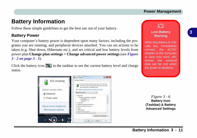
Battery InformationFollow these simple guidelines to get the best use out of your battery.
Battery PowerYour computer’s battery power is dependent upon many factors, including the pro-grams you are running, and peripheral devices attached. You can set actions to betaken (e.g. Shut down, Hibernate etc.), and set critical and low battery levels frompower plan Change plan settings > Change advanced power settings (see Figure3 - 2 on page 3 - 5).
Click the battery icon in the taskbar to see the current battery level and chargestatus.
Low Battery
Warning
When the battery is criti-cally low, immediatelyconnect the AC/DCadapter to the computeror save your work, oth-erwise, the unsaveddata will be lost whenthe power is depleted.
Figure 3 - 6Battery Icon
(Taskbar) & Battery Advanced Settings
Battery Information 3 - 11
Power Management
3
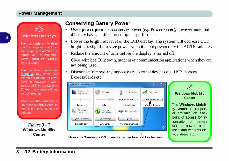
Conserving Battery Power• Use a power plan that conserves power (e.g Power saver), however note that
this may have an affect on computer performance.
• Lower the brightness level of the LCD display. The system will decrease LCD brightness slightly to save power when it is not powered by the AC/DC adapter.
• Reduce the amount of time before the display is turned off.
• Close wireless, Bluetooth, modem or communication applications when they are not being used.
• Disconnect/remove any unnecessary external devices e.g. USB devices, ExpressCards etc.
Wireless Hot Keys
The computer’s wirelessfunction keys will not func-tion properly if Wireless isturned OFF in the Win-dows Mobility Centercontrol panel.
The wireless indicators may show that
the WLAN module is pow-ered on, however if wire-less is OFF in the MobilityCenter, the module will notbe powered on.
Make sure that Wireless isON in the Mobility Center toensure proper function keybehavior.
Figure 3 - 7Windows Mobility
Center
Windows Mobility
Center
The Windows Mobili-ty Center control pan-el provides an easypoint of access for in-formation on batterystatus, power plansused and wireless de-vice status etc.
Make sure Wireless is ON to ensure proper function key behavior.
3 - 12 Battery Information

Power Management
3
Battery LifeBattery life may be shortened through improper maintenance. To optimize the lifeand improve its performance, fully discharge and recharge the battery at leastonce every 30 days.
We recommend that you do not remove the battery yourself. If you do need to re-move the battery for any reason (e.g. long term storage) see “Removing the Battery”on page 6 - 3.
New BatteryAlways completely discharge, then fully charge, a new battery (see “Battery FAQ”on page 3 - 15 for instructions on how to do this).
Recharging the Battery with the AC/DC AdapterThe battery pack automatically recharges when the AC/DC adapter is attached andplugged into an electrical outlet. If the computer is powered on, and in use, it willtake several hours to fully recharge the battery. When the computer is turned off butplugged into an electrical outlet, battery charge time is less. (Refer to “LED Indica-tors” on page 1 - 9 for information on the battery charge status, and to “ResumingOperation” on page 3 - 9 for more information on how to maintain and properly re-charge the battery pack.)
Battery Information 3 - 13
Power Management
3
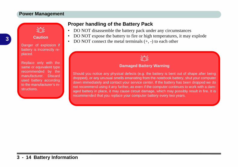
Proper handling of the Battery Pack• DO NOT disassemble the battery pack under any circumstances• DO NOT expose the battery to fire or high temperatures, it may explode• DO NOT connect the metal terminals (+, -) to each other
Caution
Danger of explosion ifbattery is incorrectly re-placed.
Replace only with thesame or equivalent typerecommended by themanufacturer. Discardused battery accordingto the manufacturer’s in-structions.
Damaged Battery Warning
Should you notice any physical defects (e.g. the battery is bent out of shape after beingdropped), or any unusual smells emanating from the notebook battery, shut your computerdown immediately and contact your service center. If the battery has been dropped we donot recommend using it any further, as even if the computer continues to work with a dam-aged battery in place, it may cause circuit damage, which may possibly result in fire. It isrecommended that you replace your computer battery every two years.
3 - 14 Battery Information
Power Management
3
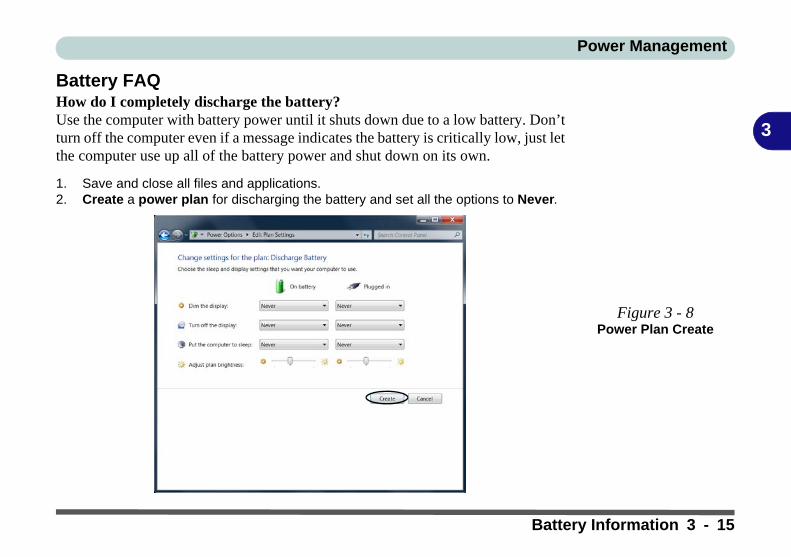
Battery FAQHow do I completely discharge the battery?Use the computer with battery power until it shuts down due to a low battery. Don’tturn off the computer even if a message indicates the battery is critically low, just letthe computer use up all of the battery power and shut down on its own.
1. Save and close all files and applications.2. Create a power plan for discharging the battery and set all the options to Never.
Figure 3 - 8Power Plan Create
Battery Information 3 - 15
Power Management
3
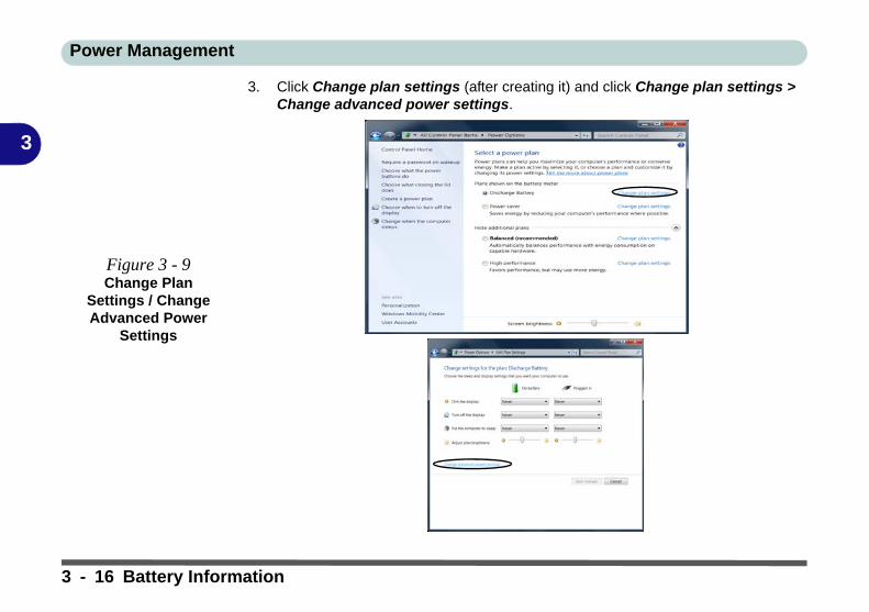
3. Click Change plan settings (after creating it) and click Change plan settings > Change advanced power settings.
Figure 3 - 9Change Plan
Settings / Change Advanced Power
Settings
3 - 16 Battery Information

Power Management
3
4. Scroll down to Battery and click + to expand the battery options.5. Choose the options below (click Yes if a warning appears):
• Low battery levels = 0%• Critical battery Levels = 0%• Low battery action = Do Nothing• Critical battery action (On battery) = Shut Down• Critical battery action (Plugged in) = Do Nothing
Figure 3 - 10Power Options
Advanced Settings - Battery
Battery Information 3 - 17

Power Management
3
How do I fully charge the battery?When charging the battery, don’t stop until the LED charging indicator light changesfrom orange to green.
How do I maintain the battery?Completely discharge and charge the battery at least once every 30 days or afterabout 20 partial discharges.
3 - 18 Battery Information
Drivers & Utilities
4
Chapter 4: Drivers & UtilitiesThis chapter deals with installing the drivers and utili-ties essential to the operation or improvement of someof the computer’s subsystems. The system takes ad-vantage of some newer hardware components forwhich the latest versions of most available operatingsystems haven’t built in drivers and utilities. Thus,some of the system components won’t be auto-config-ured with an appropriate driver or utility during oper-ating system installation. Instead, you need tomanually install some system-required drivers andutilities.
What to InstallYou will need to attach an optical device drive to thecomputer in order to access the drivers on the DeviceDrivers & Utilities + User’s Manual disc. This con-tains the drivers and utilities necessary for the properoperation of the computer.
Table 4 - 1, on page 4 - 3 lists what you need to installand it is very important that the drivers are in-stalled in the order indicated.
Module Driver InstallationThe procedures for installing drivers for the WirelessLAN, PC Camera, 3.75G/HSPA and Bluetoothmodules are provided in “Modules & Options” onpage 7 - 1.
Make sure any modules (e.g. WLAN, PC Camera,3.75G/HSPA or Bluetooth) are ON before installingthe appropriate driver.
What to Install 4 - 1
Drivers & Utilities
4
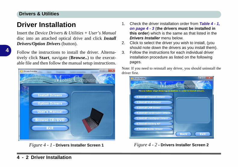
Driver InstallationInsert the Device Drivers & Utilities + User’s Manualdisc into an attached optical drive and click InstallDrivers/Option Drivers (button).
Follow the instructions to install the driver. Alterna-tively click Start, navigate (Browse..) to the execut-able file and then follow the manual setup instructions.
Figure 4 - 1 - Drivers Installer Screen 1
1. Check the driver installation order from Table 4 - 1, on page 4 - 3 (the drivers must be installed in this order) which is the same as that listed in the Drivers Installer menu below.
2. Click to select the driver you wish to install, (you should note down the drivers as you install them).
3. Follow the instructions for each individual driver installation procedure as listed on the following pages.
Note: If you need to reinstall any driver, you should uninstall thedriver first.
Figure 4 - 2 - Drivers Installer Screen 2
4 - 2 Driver Installation
Drivers & Utilities
4
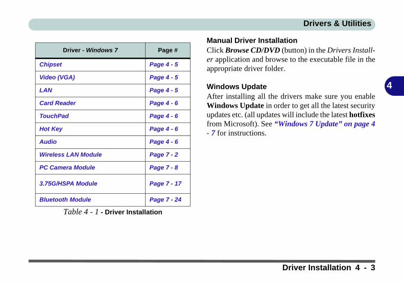
Table 4 - 1 - Driver Installation
Manual Driver InstallationClick Browse CD/DVD (button) in the Drivers Install-er application and browse to the executable file in theappropriate driver folder.
Windows UpdateAfter installing all the drivers make sure you enableWindows Update in order to get all the latest securityupdates etc. (all updates will include the latest hotfixesfrom Microsoft). See “Windows 7 Update” on page 4- 7 for instructions.
Driver - Windows 7 Page #
Chipset Page 4 - 5
Video (VGA) Page 4 - 5
LAN Page 4 - 5
Card Reader Page 4 - 6
TouchPad Page 4 - 6
Hot Key Page 4 - 6
Audio Page 4 - 6
Wireless LAN Module Page 7 - 2
PC Camera Module Page 7 - 8
3.75G/HSPA Module Page 7 - 17
Bluetooth Module Page 7 - 24
Driver Installation 4 - 3

Drivers & Utilities
4
Updating/Reinstalling Individual DriversIf you wish to update/reinstall individual drivers itmay be necessary to uninstall the original driver.To dothis go to the Control Panel in the Windows OS anddouble-click the Programs and Features icon (Pro-grams > Uninstall a program). Click to select thedriver (if it is not listed see below) and click Uninstall,and then follow the on screen prompts (it may be nec-essary to restart the computer). Reinstall the driver asoutlined in this chapter.
If the driver is not listed in the Programs and Fea-tures menu:
1. Click Start, and click Control Panel (or point to Settings and click Control Panel).
2. Double-click Device Manager (Hardware and Sound > Device Manager).
3. Double-click the device you wish to update/reinstall the driver for (you may need to click “+” to expand the selection).
4. Click Driver (tab) and click the Update Driver or Uninstall button and follow the on screen prompts.
User Account ControlIf a User Account Control prompt appears as part ofthe driver installation procedure, click Continue orAllow, and follow the installation procedure as direct-ed.
Windows Security MessageIf you receive a Windows security message as part ofthe driver installation process. Just click “Install thisdriver software anyway” or “Install” to continue theinstallation procedure.
You will receive this message in cases where the driv-er has been released after the version of Windows youare currently using. All the drivers provided will havealready received certification for Windows.
4 - 4 Driver Installation

Drivers & Utilities
4
New Hardware FoundIf you see the message “New Hardware Found” dur-ing the installation procedure (other than when out-lined in the driver install procedure), click Cancelto close the window, and follow the installation proce-dure.
Driver Installation ProcedureInsert the Device Drivers & Utilities + User’s Manualdisc into your attached CD/DVD drive and click In-stall Drivers (button).
Chipset1. Click 1.Install Chipset Driver > Yes.2. Click Next > Yes > Next > Next.3. Click Finish to restart the computer.
Video (VGA)1. Click 2.Install VGA Driver > Yes.2. Click Next > Yes > Next > Next.3. Click Finish to restart the computer.
LAN1. Click 3.Install LAN Driver > Yes.2. Click Install > Finish to complete the installa-
tion.3. The network settings can now be configured.
Driver Installation General Guidelines
The driver installation procedure outlined in this Chapter(and in Chapter 7 Options & Modules), are accurate atthe time of going to press.
Drivers are always subject to upgrade and revision sothe exact procedure for certain drivers may differ slight-ly. As a general guide follow the default on screen in-structions for each driver (e.g. Next > Next > Finish)unless you are an advanced user. In many cases a re-start is required to install the driver.
Make sure any modules (e.g. PC Camera, WLAN or3.75G/HSPA) are ON before installing the appropriatedriver.
Driver Installation 4 - 5
Drivers & Utilities
4
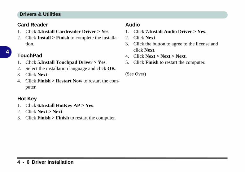
Card Reader1. Click 4.Install Cardreader Driver > Yes.2. Click Install > Finish to complete the installa-
tion.
TouchPad1. Click 5.Install Touchpad Driver > Yes.2. Select the installation language and click OK.3. Click Next.4. Click Finish > Restart Now to restart the com-
puter.
Hot Key1. Click 6.Install HotKey AP > Yes.2. Click Next > Next.3. Click Finish > Finish to restart the computer.
Audio1. Click 7.Install Audio Driver > Yes. 2. Click Next.3. Click the button to agree to the license and
click Next.4. Click Next > Next > Next.5. Click Finish to restart the computer.
(See Over)
4 - 6 Driver Installation

Drivers & Utilities
4
Windows Experience IndexAfter the drivers are installed follow this procedure toensure an accurate rating from the Windows Experi-ence Index:
1. Click Start, and click Control Panel.2. Click Performance Information and Tools
(System and Security > System > Check the Windows Experience Index).
3. Click “Rate this computer”.4. The computer will take a few minutes to assess
the system performance.5. Close the control panel.
Windows 7 Update
After installing all the drivers make sure you enable Win-dows Update in order to get all the latest security up-dates etc. (all updates will include the latest hotfixesfrom Microsoft).
To enable Windows Update make sure you are con-nected to the internet:
1. Click Start, and click Control Panel (or point to Settings and click Control Panel).
2. Click Windows Update (System and Security).3. Click Check for updates (button).4. The computer will now check for updates (you
need to be connected to the internet).5. Click Install now (button) to begin checking for the
updates.6. Click Install updates (button) to install the
updates.
Driver Installation 4 - 7
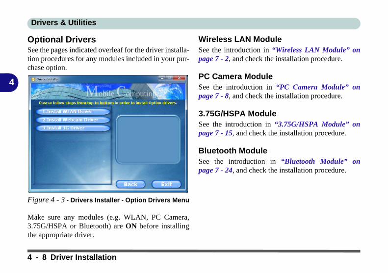
Drivers & Utilities
4
Optional DriversSee the pages indicated overleaf for the driver installa-tion procedures for any modules included in your pur-chase option.
Figure 4 - 3 - Drivers Installer - Option Drivers Menu
Make sure any modules (e.g. WLAN, PC Camera,3.75G/HSPA or Bluetooth) are ON before installingthe appropriate driver.
Wireless LAN ModuleSee the introduction in “Wireless LAN Module” onpage 7 - 2, and check the installation procedure.
PC Camera ModuleSee the introduction in “PC Camera Module” onpage 7 - 8, and check the installation procedure.
3.75G/HSPA ModuleSee the introduction in “3.75G/HSPA Module” onpage 7 - 15, and check the installation procedure.
Bluetooth ModuleSee the introduction in “Bluetooth Module” onpage 7 - 24, and check the installation procedure.
4 - 8 Driver Installation

BIOS Utilities
5
Chapter 5: BIOS Utilities
OverviewThis chapter gives a brief introduction to the computer’s built-in software:
Diagnostics: The POST (Power-On Self Test)
Configuration: The Phoenix SecureCore Setup UtilityIf your computer has never been set up, or you are making important changes to thesystem (e.g. hard disk setup), then you should review this chapter first and note theoriginal settings found in Setup. Even if you are a beginner, keep a record of the set-tings you find and any changes you make. This information could be useful if yoursystem ever needs servicing.
There is one general rule: Don’t make any changes unless you are sure of what youare doing. Many of the settings are required by the system, and changing them couldcause it to become unstable or worse. If you have any doubts, consult your servicerepresentative.
BIOS Screens
Note that the BIOSscreens pictured onthese pages are intend-ed for guidance in set-ting up your system’sBIOS.
BIOS versions are sub-ject to constant changeand revision, thereforeyour computer’s actualscreens may appearslightly different fromthose pictured on thesepages.
Overview 5 - 1
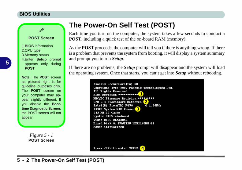
BIOS Utilities
5
The Power-On Self Test (POST)Each time you turn on the computer, the system takes a few seconds to conduct aPOST, including a quick test of the on-board RAM (memory).
As the POST proceeds, the computer will tell you if there is anything wrong. If thereis a problem that prevents the system from booting, it will display a system summaryand prompt you to run Setup.
If there are no problems, the Setup prompt will disappear and the system will loadthe operating system. Once that starts, you can’t get into Setup without rebooting.
POST Screen
1.BIOS information2.CPU type 3.Memory status4.Enter Setup prompt
appears only duringPOST
Note: The POST screenas pictured right is forguideline purposes only.The POST screen onyour computer may ap-pear slightly different. Ifyou disable the Boot-time Diagnostic Screen,the POST screen will notappear.
Figure 5 - 1POST Screen
1
2
3
4
5 - 2 The Power-On Self Test (POST)

BIOS Utilities
5
Failing the POSTErrors can be detected during the POST. There are two categories, “fatal” and “non-fatal”.
Fatal ErrorsThese stop the boot process and usually indicate there is something seriously wrongwith your system. Take the computer to your service representative or authorizedservice center as soon as possible.
Non-Fatal ErrorsThis kind of error still allows you to boot. You will get a message identifying theproblem (make a note of this message!) followed by the prompt:
• Press <F1> to resume• <F2> to enter Setup
Press F1 to see if the boot process can continue. It may work, without the correctconfiguration.
Press F2 to run the Setup program and try to correct the problem. If you still get anerror message after you change the setting, or if the “cure” seems even worse, callfor help.
The Power-On Self Test (POST) 5 - 3

BIOS Utilities
5
The Setup UtilityThe Phoenix SecureCore Setup Utility tells the system how to configure itself andmanage basic features and subsystems (e.g. port configuration).
Entering SetupTo enter Setup, turn on the computer and press F2 during the POST. The prompt(Press F2 to Enter Setup) seen on page 5 - 2 is usually present for a few secondsafter you turn on the system. If you get a “Keyboard Error”, (usually because youpressed F2 too quickly) just press F2 again.
If the computer is already on, reboot using the Ctrl + Alt + Delete combination andthen hold down F2 when prompted. The Setup main menu will appear.
BIOS Settings
Warning
Incorrect settings cancause your system tomalfunction. To correctmistakes, return to Set-up and restore the Set-up Defaults with <F9>.
5 - 4 The Setup Utility
BIOS Utilities
5
Setup ScreensThe following pages contain additional advice on portions of the Phoenix Se-cureCore Setup Utility.
Along the top of the screen is a menu bar with menu headings. When you select aheading, a new screen appears. Scroll through the features listed on each screen tomake changes to Phoenix SecureCore Setup Utility.
Instructions on how to navigate each screen are in the box along the bottom of thescreen. If these tools are confusing, press F1 to call up a General Help screen, andthen use the arrow keys to scroll up or down the page.
The Item Specific Help on the right side of each screen explains the highlighteditem and has useful messages about its options.
If you see an arrow next to an item, press Enter to go to a sub-menu on that sub-ject. The sub-menu screen that appears has a similar layout, but the Enter key mayexecute a command.
Setup Menus
The Setup menusshown in this section arefor reference only. Yourcomputer’s menus willindicate the configura-tion appropriate for yourmodel and options.
The Setup Utility 5 - 5
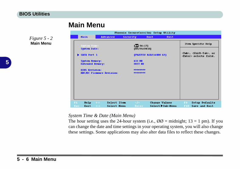
BIOS Utilities
5
Main Menu
System Time & Date (Main Menu)The hour setting uses the 24-hour system (i.e., ØØ = midnight; 13 = 1 pm). If youcan change the date and time settings in your operating system, you will also changethese settings. Some applications may also alter data files to reflect these changes.
Figure 5 - 2Main Menu
5 - 6 Main Menu
BIOS Utilities
5
SATA Port 1 (Main Menu)Pressing Enter opens the sub-menu to show the configuration of a HDD on the com-puter’s Serial ATA Port 1. Use the Auto (Type:) setting to have the items configuredautomatically for you.
System/Extended Memory (Main Menu)This item contains information on the system memory, and is not user configurable.The system will auto detect the amount of memory installed.
Main Menu 5 - 7

BIOS Utilities
5
Advanced Menu
Detect External CRT (Advanced Menu > Advanced Chipset Control)This sub-menu allows you to Enable/Disable detection for External CRT’s (exter-nal displays). You can disable detection to save system power.
Figure 5 - 3Advanced Menu
SATA Mode
Selection
If you have installed theWindows 7 operatingsystem with AHCI modeenabled (default set-ting), DO NOT disableAHCI mode (if you wishto disable AHCI modeyou will need to reinstallthe Windows 7 OS).
5 - 8 Advanced Menu
BIOS Utilities
5
SATA Mode Selection (Advanced Menu)You can configure SATA (Serial ATA) control to operate in either IDE (native/compatible) or AHCI (Advanced Host Controller Interface) modes from this menu.The SATA mode should be set to AHCI mode for this system (unless you are sureyour hard disk can only operate in IDE mode). If you are unsure of the mode yourhard disk supports contact your service center.
Legacy USB Support (Advanced Menu)Use this menu item to enable/disable the support for Legacy Universal Serial Bus innon-USB aware operating systems.
Boot-time Diagnostic Screen (Advanced Menu)Use this menu item to enable/disable the Boot-time Diagnostic Screen or POSTscreen (see “The Power-On Self Test (POST)” on page 5 - 2).
Power On Boot Beep (Advanced Menu)Use this menu item to enable/disable the beep as the computer starts up.
Battery Low Alarm Beep (Advanced Menu)Use this menu item to enable/disable the audible warning when the battery hasreached low power status.
Advanced Menu 5 - 9

BIOS Utilities
5
Security Menu
Set Supervisor Password (Security Menu)You can set a password for access to the Phoenix SecureCore Setup Utility. Thiswill not affect access to the computer OS (only the Phoenix SecureCore SetupUtility).
Security Menu
The changes youmake here affect theaccess to the Setuputility itself, and alsoaccess to your ma-chine as it boots up af-ter you turn it on.These settings do notaffect your machine ornetwork passwordswhich will be set inyour software OS.
Figure 5 - 4Security Menu
5 - 10 Security Menu
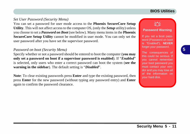
BIOS Utilities
5
Set User Password (Security Menu)You can set a password for user mode access to the Phoenix SecureCore SetupUtility. This will not affect access to the computer OS, (only the Setup utility) unlessyou choose to set a Password on Boot (see below). Many menu items in the PhoenixSecureCore Setup Utility cannot be modified in user mode. You can only set theuser password after you have set the supervisor password.
Password on boot (Security Menu)Specify whether or not a password should be entered to boot the computer (you mayonly set a password on boot if a supervisor password is enabled). If “Enabled”is selected, only users who enter a correct password can boot the system (see thewarning in the sidebar). The default setting is “Disabled”.
Note: To clear existing passwords press Enter and type the existing password, thenpress Enter for the new password (without typing any password entry) and Enteragain to confirm the password clearance.
Password Warning
If you set a boot pass-word (Password on bootis “Enabled“), NEVERforget your password.
The consequences ofthis could be serious. Ifyou cannot rememberyour boot password youmust contact your ven-dor and you may lose allof the information onyour hard disk.
Security Menu 5 - 11
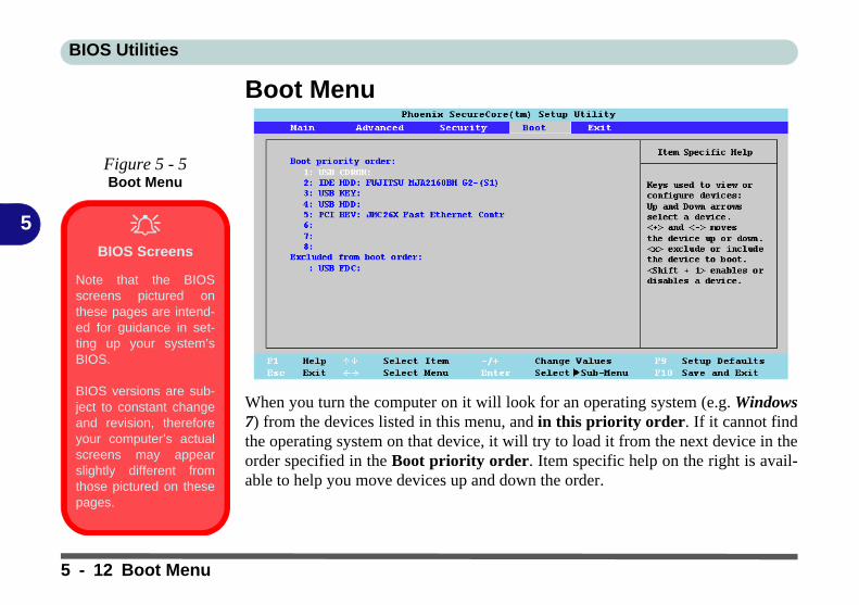
BIOS Utilities
5
Boot Menu
When you turn the computer on it will look for an operating system (e.g. Windows7) from the devices listed in this menu, and in this priority order. If it cannot findthe operating system on that device, it will try to load it from the next device in theorder specified in the Boot priority order. Item specific help on the right is avail-able to help you move devices up and down the order.
Figure 5 - 5Boot Menu
BIOS Screens
Note that the BIOSscreens pictured onthese pages are intend-ed for guidance in set-ting up your system’sBIOS.
BIOS versions are sub-ject to constant changeand revision, thereforeyour computer’s actualscreens may appearslightly different fromthose pictured on thesepages.
5 - 12 Boot Menu

BIOS Utilities
5
Exit Menu
Choosing to Discard Changes, or Exit Discarding Changes, will wipe out anychanges you have made to the Setup. You can also choose to restore the original Set-up defaults that will return the Setup to its original state, and erase any previouschanges you have made in a previous session.
Figure 5 - 6Exit Menu
Exit Menu 5 - 13

BIOS Utilities
5
5 - 14

Upgrading The Computer
6
Chapter 6: Upgrading The Computer
OverviewThis chapter contains information on upgrading the computer. Follow the steps out-lined to make the desired upgrades. If you have any trouble or problems you can con-tact your service representative for further help. Before you begin you will need:
• A small crosshead or Phillips screwdriver• A small regular slotted (flathead) screwdriver• An antistatic wrist strap
Before working with the internal components you will need to wear an antistaticwrist strap to ground yourself because static electricity may damage the compo-nents.
The chapter includes:
• Removing the Battery• Upgrading the System Memory (RAM)• Changing the Optional LCD Back Covers
Please make sure that you review each procedure before you perform it.
Warranty Warning
Please check with yourservice representativebefore undertaking anyupgrade procedures tofind out if this will VOIDyour warranty.
The CPU is not a userserviceable part. Ac-cessing the CPU in anyway, may violate yourwarranty.
Unauthorized tamperingwith the HDD may alsoviolate your warranty.
Overview 6 - 1
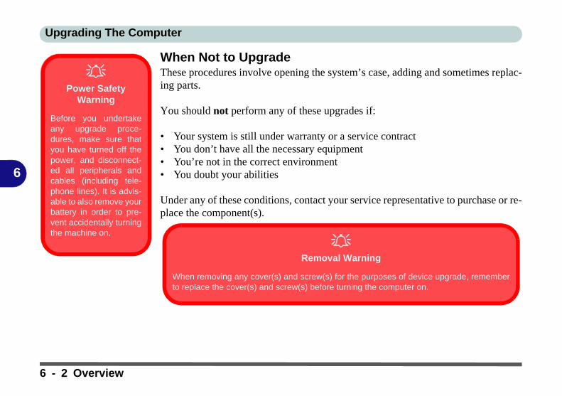
Upgrading The Computer
6
When Not to UpgradeThese procedures involve opening the system’s case, adding and sometimes replac-ing parts.
You should not perform any of these upgrades if:
• Your system is still under warranty or a service contract• You don’t have all the necessary equipment • You’re not in the correct environment• You doubt your abilities
Under any of these conditions, contact your service representative to purchase or re-place the component(s).
Power Safety
Warning
Before you undertakeany upgrade proce-dures, make sure thatyou have turned off thepower, and disconnect-ed all peripherals andcables (including tele-phone lines). It is advis-able to also remove yourbattery in order to pre-vent accidentally turningthe machine on.
Removal Warning
When removing any cover(s) and screw(s) for the purposes of device upgrade, rememberto replace the cover(s) and screw(s) before turning the computer on.
6 - 2 Overview

Upgrading The Computer
6
Removing the BatteryIf you are confident in undertaking upgrade procedures yourself, for safety reasonsit is best to remove the battery.
1. Turn the computer off, and turn it over.2. Slide the latch in the direction of the arrow.3. Slide the latch in the direction of the arrow, and hold it in place.4. Slide the battery out in the direction of the arrow ..
Warranty Warning
Please check with yourservice representativebefore undertaking anyupgrade procedures tofind out if this will VOIDyour warranty.
Figure 6 - 1Battery Removal
12
3
3
2 1
Re-Inserting the Battery
Make sure you align the grooves onthe side of the battery with the pinsin the battery bay when re-insertingthe battery.
Removing the Battery 6 - 3

Upgrading The Computer
6
Upgrading the System Memory (RAM)The computer has one memory socket for 200 pin Small Outline Dual In-line (SO-DIMM) DDRII (DDR2) type memory modules (see “Memory” on page C - 2 fordetails of supported module types).
The total memory size is automatically detected by the POST routine once you turnon your computer.
1. Turn off the computer, and remove the battery.2. Locate the component bay cover and remove screw .3. Carefully lift the component bay cover up.
Figure 6 - 2Component Bay Cover Removal
152
2
1
6 - 4 Upgrading the System Memory (RAM)

Upgrading The Computer
6
4. Gently pull the two release latches on the sides of the memory socket in the direction indicated by the arrows ( & ) in Figure 6 - 3.
5. The RAM module will pop-up, and you can remove it.
3 4
Figure 6 - 3RAM Module
Release Latches
Contact Warning
Be careful not to touchthe metal pins on themodule’s connectingedge. Even the cleanesthands have oils whichcan attract particles, anddegrade the module’sperformance.
Figure 6 - 4RAM Module
Removal
43
5
5
Upgrading the System Memory (RAM) 6 - 5
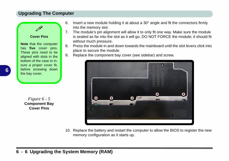
Upgrading The Computer
6
6. Insert a new module holding it at about a 30° angle and fit the connectors firmly into the memory slot.
7. The module’s pin alignment will allow it to only fit one way. Make sure the module is seated as far into the slot as it will go. DO NOT FORCE the module; it should fit without much pressure.
8. Press the module in and down towards the mainboard until the slot levers click into place to secure the module.
9. Replace the component bay cover (see sidebar) and screw.
10. Replace the battery and restart the computer to allow the BIOS to register the new memory configuration as it starts up.
Cover Pins
Note that the computerhas five cover pins.These pins need to bealigned with slots in thebottom of the case to in-sure a proper cover fit,before screwing downthe bay cover.
Figure 6 - 5Component Bay
Cover Pins
6 - 6 Upgrading the System Memory (RAM)
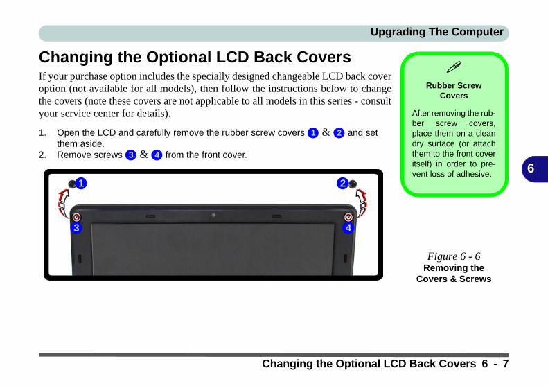
Upgrading The Computer
6
Changing the Optional LCD Back CoversIf your purchase option includes the specially designed changeable LCD back coveroption (not available for all models), then follow the instructions below to changethe covers (note these covers are not applicable to all models in this series - consultyour service center for details).
1. Open the LCD and carefully remove the rubber screw covers & and set them aside.
2. Remove screws & from the front cover.
Rubber Screw
Covers
After removing the rub-ber screw covers,place them on a cleandry surface (or attachthem to the front coveritself) in order to pre-vent loss of adhesive.
Figure 6 - 6Removing the
Covers & Screws
1 2
3 4
1
3
2
4
Changing the Optional LCD Back Covers 6 - 7

Upgrading The Computer
6
3. Carefully slide the cover forward in the direction of the arrows & as illustrated below.
4. Remove the LCD back cover .
Figure 6 - 7Slide the Cover
Forward
Figure 6 - 8Remove the LCD
Back Cover
5 6
5 6
7
7
6 - 8 Changing the Optional LCD Back Covers
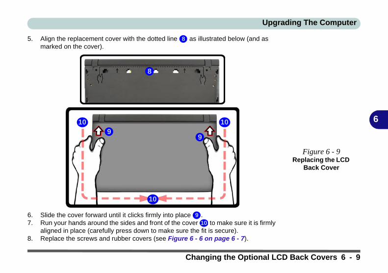
Upgrading The Computer
6
5. Align the replacement cover with the dotted line as illustrated below (and as marked on the cover).
6. Slide the cover forward until it clicks firmly into place .7. Run your hands around the sides and front of the cover to make sure it is firmly
aligned in place (carefully press down to make sure the fit is secure).8. Replace the screws and rubber covers (see Figure 6 - 6 on page 6 - 7).
Figure 6 - 9Replacing the LCD
Back Cover
8
8
910
10
9
10
910
Changing the Optional LCD Back Covers 6 - 9

Upgrading The Computer
6
Upgrading the Hard DiskIf you want to upgrade your computer by replacing the existing hard disk with a fast-er/new one you will need to contact your customer service representative. We rec-ommend that you do not do this yourself, since if it is done incorrectly you maydamage the computer and may violate your warranty.
Warranty
The CPU is not a userserviceable part. Ac-cessing the CPU in anyway, may violate yourwarranty.
Unauthorized tamperingwith the HDD may alsoviolate your warranty.
6 - 10 Upgrading the Hard Disk
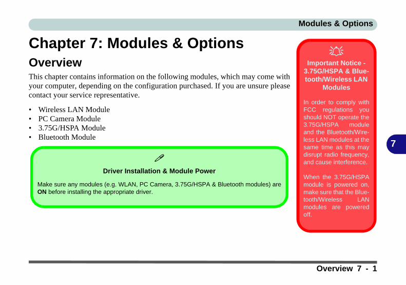
Modules & Options
7
Chapter 7: Modules & OptionsOverviewThis chapter contains information on the following modules, which may come withyour computer, depending on the configuration purchased. If you are unsure pleasecontact your service representative.
• Wireless LAN Module• PC Camera Module• 3.75G/HSPA Module• Bluetooth Module
Important Notice -
3.75G/HSPA & Blue-tooth/Wireless LAN
Modules
In order to comply withFCC regulations youshould NOT operate the3.75G/HSPA moduleand the Bluetooth/Wire-less LAN modules at thesame time as this maydisrupt radio frequency,and cause interference.
When the 3.75G/HSPAmodule is powered on,make sure that the Blue-tooth/Wireless LANmodules are poweredoff.
Driver Installation & Module Power
Make sure any modules (e.g. WLAN, PC Camera, 3.75G/HSPA & Bluetooth modules) areON before installing the appropriate driver.
Overview 7 - 1
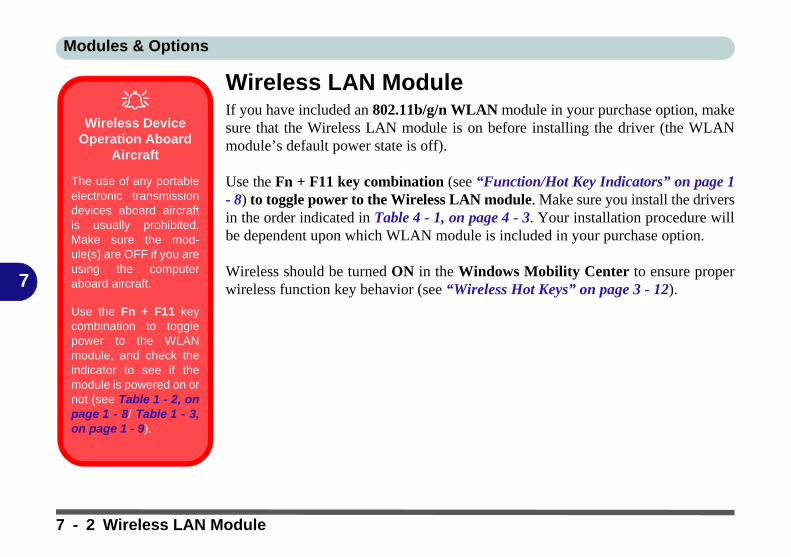
Modules & Options
7
Wireless LAN ModuleIf you have included an 802.11b/g/n WLAN module in your purchase option, makesure that the Wireless LAN module is on before installing the driver (the WLANmodule’s default power state is off).
Use the Fn + F11 key combination (see “Function/Hot Key Indicators” on page 1- 8) to toggle power to the Wireless LAN module. Make sure you install the driversin the order indicated in Table 4 - 1, on page 4 - 3. Your installation procedure willbe dependent upon which WLAN module is included in your purchase option.
Wireless should be turned ON in the Windows Mobility Center to ensure properwireless function key behavior (see “Wireless Hot Keys” on page 3 - 12).
Wireless Device
Operation Aboard Aircraft
The use of any portableelectronic transmissiondevices aboard aircraftis usually prohibited.Make sure the mod-ule(s) are OFF if you areusing the computeraboard aircraft.
Use the Fn + F11 keycombination to togglepower to the WLANmodule, and check theindicator to see if themodule is powered on ornot (see Table 1 - 2, onpage 1 - 8/ Table 1 - 3,on page 1 - 9).
7 - 2 Wireless LAN Module
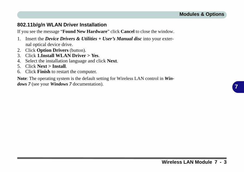
Modules & Options
7
802.11b/g/n WLAN Driver InstallationIf you see the message “Found New Hardware” click Cancel to close the window.
1. Insert the Device Drivers & Utilities + User’s Manual disc into your exter-nal optical device drive.
2. Click Option Drivers (button).3. Click 1.Install WLAN Driver > Yes.4. Select the installation language and click Next.5. Click Next > Install.6. Click Finish to restart the computer.
Note: The operating system is the default setting for Wireless LAN control in Win-dows 7 (see your Windows 7 documentation).
Wireless LAN Module 7 - 3
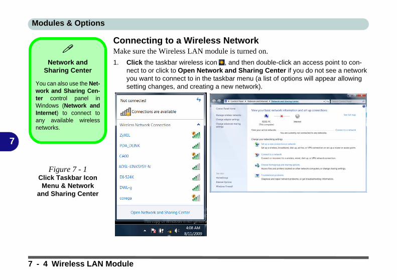
Modules & Options
7
Connecting to a Wireless NetworkMake sure the Wireless LAN module is turned on.
1. Click the taskbar wireless icon , and then double-click an access point to con-nect to or click to Open Network and Sharing Center if you do not see a network you want to connect to in the taskbar menu (a list of options will appear allowing setting changes, and creating a new network).
Network and
Sharing Center
You can also use the Net-work and Sharing Cen-ter control panel inWindows (Network andInternet) to connect toany available wirelessnetworks.
Figure 7 - 1Click Taskbar Icon Menu & Network
and Sharing Center
7 - 4 Wireless LAN Module

Modules & Options
7
2. You may need to enter a security key for any access point to which you are trying to connect.
3. Click to select a network location (e.g. Home, Work or Public).4. Click “View or change settings in Network and Sharing Center” to access
further options for the connection.Figure 7 - 2
Network Location Set
Wireless LAN Module 7 - 5
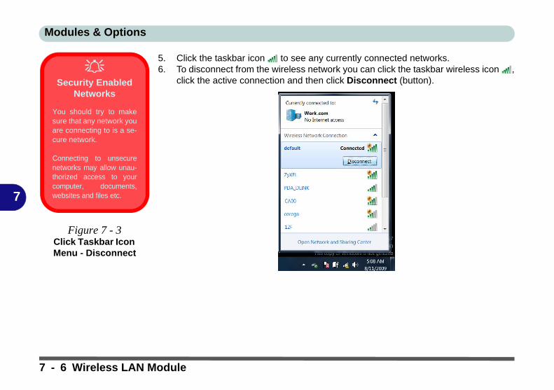
Modules & Options
7
5. Click the taskbar icon to see any currently connected networks.6. To disconnect from the wireless network you can click the taskbar wireless icon ,
click the active connection and then click Disconnect (button).
Security Enabled
Networks
You should try to makesure that any network youare connecting to is a se-cure network.
Connecting to unsecurenetworks may allow unau-thorized access to yourcomputer, documents,websites and files etc.
Figure 7 - 3Click Taskbar Icon Menu - Disconnect
7 - 6 Wireless LAN Module

Modules & Options
7
Windows Mobility CenterThe Windows Mobility Center control panel provides an easy point of access forinformation on battery status, power plans used and wireless device status etc.
To access the Windows Mobility Center:
1. Click Start, and click Control Panel (or point to Settings and click Control Panel).
2. Double-click Windows Mobility Center (Mobile PC).3. Click the button to Turn wireless off/on, or click the icon to access the network
menu.
Wireless Hot Keys
The computer’s wirelessfunction keys will not func-tion properly if Wireless isturned OFF in the Win-dows Mobility Centercontrol panel.
The wireless indicators may show that
the WLAN module is pow-ered on, however if wire-less is OFF in the MobilityCenter, the module will notbe powered on.
Make sure that Wireless isON in the Mobility Center toensure proper function keybehavior.
Figure 7 - 4Windows Mobility
CenterMake sure Wireless is ON to ensure proper function key behavior.
Wireless LAN Module 7 - 7

Modules & Options
7
PC Camera ModuleThe PC Camera application captures video files and takes pictures. Before installingthe driver, make sure that the optional PC Camera is on. Use the Fn + F10 key com-bination (see “Function/Hot Key Indicators” on page 1 - 8) to toggle power to thePC Camera module. Make sure you install the drivers in the order indicated inTable 4 - 1, on page 4 - 3.
There are a number of different camera modules available with this computer modelseries. You will have the appropriate application installed for your camera (notethat some versions of the camera application do not support the zoom function).Make sure you access the application via the desktop shortcut.
Latest PC Camera Driver Information
Check the Device Driv-ers & Utilities + User’sManual disc, and anyaccompanying insertpages, for the latest up-dated information on thePC Camera driver,which may override theinformation providedhere.
PC Camera Driver Uninstallation
If you need to uninstallthe driver, then uninstallthe WebCam Installeritem from the Programsand Features controlpanel in Windows.
7 - 8 PC Camera Module
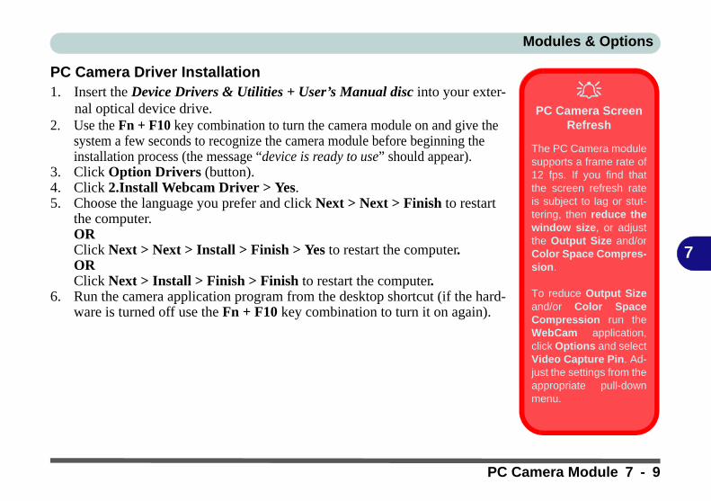
Modules & Options
7
PC Camera Driver Installation1. Insert the Device Drivers & Utilities + User’s Manual disc into your exter-
nal optical device drive.2. Use the Fn + F10 key combination to turn the camera module on and give the
system a few seconds to recognize the camera module before beginning the installation process (the message “device is ready to use” should appear).
3. Click Option Drivers (button).4. Click 2.Install Webcam Driver > Yes.5. Choose the language you prefer and click Next > Next > Finish to restart
the computer.ORClick Next > Next > Install > Finish > Yes to restart the computer.ORClick Next > Install > Finish > Finish to restart the computer.
6. Run the camera application program from the desktop shortcut (if the hard-ware is turned off use the Fn + F10 key combination to turn it on again).
PC Camera Screen
Refresh
The PC Camera modulesupports a frame rate of12 fps. If you find thatthe screen refresh rateis subject to lag or stut-tering, then reduce thewindow size, or adjustthe Output Size and/orColor Space Compres-sion.
To reduce Output Sizeand/or Color SpaceCompression run theWebCam application,click Options and selectVideo Capture Pin. Ad-just the settings from theappropriate pull-downmenu.
PC Camera Module 7 - 9
Modules & Options
7
PC Camera Audio SetupIf you wish to capture video & audio with your camera, it is necessary to setup theaudio recording options in Windows.
1. Click Start, and click Control Panel (or point to Settings and click Control Panel).2. Click Sound (Hardware and Sound).3. Click Recording (tab).4. Right-click Microphone (VIA High Definition Audio) and make sure the item is not
disabled.5. Double-click Microphone (or select Properties from the right-click menu).6. Click Levels (tab), and adjust the Microphone and Microphone Boost sliders to
the level required.7. Click OK and close the control panels.8. Run the camera application program from the desktop shortcut.9. Go to the Devices menu heading and select Microphone (VIA....) (it should have
a tick alongside it).10. Go to the Capture menu heading and select Capture Audio (it should have a tick
alongside it).
7 - 10 PC Camera Module
Modules & Options
7
Camera ApplicationThe camera application is a video viewer for general purpose video viewing and test-ing, and for capturing video files to .avi format.
1. Run the camera application from the desktop shortcut (it is recommended that you set the capture file before the capture process - see “Set Capture File” on page 7 - 11).
2. Go to the Capture menu heading (if you wish to capture audio check “PC Camera Audio Setup” on page 7 - 10) and select Start Capture.
3. Click OK/Yes (the file location will be displayed in the pop-up box) to start capturing the video, and press Esc to stop the capture (you can view the file using the Windows Media Player).
Set Capture FilePrior to capturing video files you may select the Set Capture File... option in theFile menu, and set the file name and location before capture (this will help avoid ac-cidentally overwriting files). Set the name and location then click Open, then set the"Capture file size:" and click OK. You can then start the capture process as on theprevious page.
Note the important information in reducing video file size below in order tosave file space, and help prevent system problems.
Pre-Allocating File
Size/Space
You may pre-allocate thefile size (File > AllocateFile Size/Space) for thecapture file in the cameraprogram (you may needto set a folder locationfirst).
Pre-allocating space onthe hard disk can improvethe capture quality (par-ticularly of large capturefiles), by reducing theamount of work the harddisk has to do in findingspace for the video dataas it is being captured.
See also “Reducing Vid-eo File Size” on page 7 -12.
PC Camera Module 7 - 11

Modules & Options
7
Reducing Video File SizeNote that capturing high resolution video files requires a substantial amount of diskspace for each file. After recording video, check the video file size (right-click thefile and select Properties) and the remaining free space on your hard disk (go to MyComputer, right-click the hard disk, and select Properties). If necessary you canremove the recorded video file to a removable medium e.g. CD, DVD or USB Flashdrive.
Note that the Windows 7 system requires a minimum of 15GB of free space on theC: drive system partition. In order to prevent system problems it is recommendedthat you save the captured video file to a location other than the C: drive (see setcapture file above), limit the file size of the captured video (see “Pre-Allocating FileSize/Space” on page 7 - 11) or reduce video resolution (see below).
To Reduce Video Resolution Output Size:
1. Run the camera application program from the desktop shortcut.2. Go to Options and scroll down to select Video Capture Pin....3. Click the Output Size drop box and select a lower resolution size in order to
reduce the captured file size.4. Click OK.
7 - 12 PC Camera Module
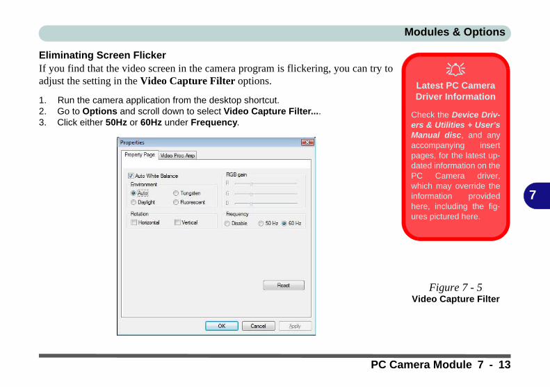
Modules & Options
7
Eliminating Screen FlickerIf you find that the video screen in the camera program is flickering, you can try toadjust the setting in the Video Capture Filter options.
1. Run the camera application from the desktop shortcut.2. Go to Options and scroll down to select Video Capture Filter....3. Click either 50Hz or 60Hz under Frequency.
Latest PC Camera Driver Information
Check the Device Driv-ers & Utilities + User’sManual disc, and anyaccompanying insertpages, for the latest up-dated information on thePC Camera driver,which may override theinformation providedhere, including the fig-ures pictured here.
Figure 7 - 5Video Capture Filter
PC Camera Module 7 - 13

Modules & Options
7
ZoomThe camera program allows you to zoom the camera in and out.
1. Run the camera application from the desktop shortcut.2. Go to Zoom and select Zoom Out/Zoom In.
Taking Still PicturesThe camera program allows you to take still pictures.
1. Run the camera application from the desktop shortcut.2. Go to Options and select Take Picture/Snapshot.3. The picture (in JPEG format) will be placed in the Snapshot folder on the
desktop (see sidebar).
Figure 7 - 6Zoom/Setting
Snapshot Folder
The Snapshot folder’s de-fault location is on the desk-top. Do not move this folderor an error may appearwhen you try to take a stillpicture.
If you accidentally delete ormove the folder, you cancreate a new Snapshotfolder on the desktop in or-der to capture the files.
7 - 14 PC Camera Module
Modules & Options
7
3.75G/HSPA ModuleIf you have included an optional 3.75G/HSPA (High Speed Packet Access) modulein your purchase option, you will have the appropriate application provided for yourparticular module. Follow the instructions on page 1 - 13 to install the USIM card(supplied by your service provider), and then install the application (see over for fur-ther details).
3.75G/HSPA Module 7 - 15
Modules & Options
7
Before installing the application, make sure that the 3.75G/HSPA module is ON(installing the driver with the module off will not allow the software to detect themodule hardware correctly). Use the Fn + key combination (see “Function/HotKey Indicators” on page 1 - 8) to toggle power to the 3.75G/HSPA module. Notethat exiting the application does NOT turn off the 3.75G/HSPA module.
• Mobile Partner - See “Mobile Partner Application Installation” on page 7 - 17 for driver installation information and “Mobile Partner Application” on page 7 - 18 for instructions on using the Mobile Partner application.
3.75G/HSPA
Modules & System Wake Up
Note that the 3.75G mod-ules DO NOT supportsystem wake up on3.75G/HSPA modem ac-tivity.
7 - 16 3.75G/HSPA Module
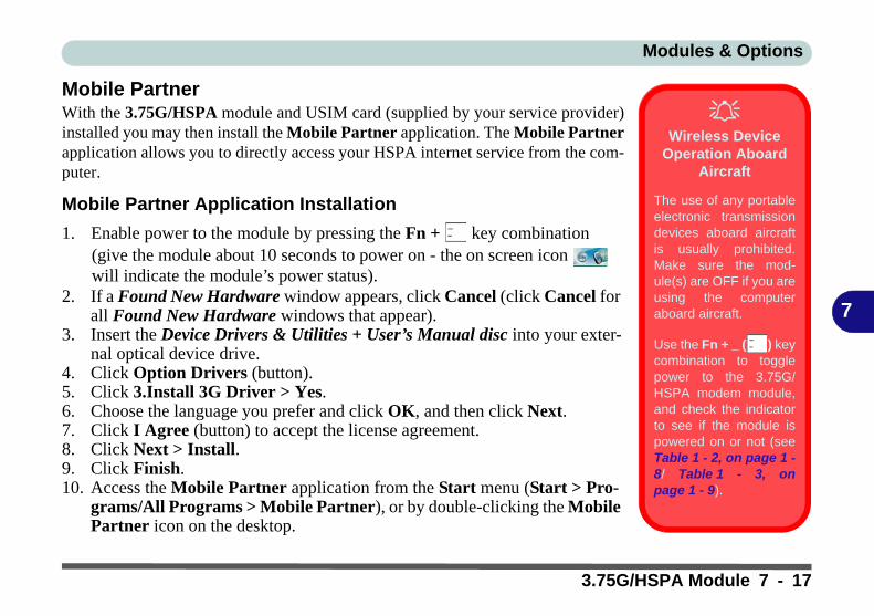
Modules & Options
7
Mobile PartnerWith the 3.75G/HSPA module and USIM card (supplied by your service provider)installed you may then install the Mobile Partner application. The Mobile Partnerapplication allows you to directly access your HSPA internet service from the com-puter.
Mobile Partner Application Installation
1. Enable power to the module by pressing the Fn + key combination (give the module about 10 seconds to power on - the on screen icon will indicate the module’s power status).
2. If a Found New Hardware window appears, click Cancel (click Cancel for all Found New Hardware windows that appear).
3. Insert the Device Drivers & Utilities + User’s Manual disc into your exter-nal optical device drive.
4. Click Option Drivers (button).5. Click 3.Install 3G Driver > Yes.6. Choose the language you prefer and click OK, and then click Next.7. Click I Agree (button) to accept the license agreement.8. Click Next > Install.9. Click Finish.10. Access the Mobile Partner application from the Start menu (Start > Pro-
grams/All Programs > Mobile Partner), or by double-clicking the Mobile Partner icon on the desktop.
Wireless Device
Operation Aboard Aircraft
The use of any portableelectronic transmissiondevices aboard aircraftis usually prohibited.Make sure the mod-ule(s) are OFF if you areusing the computeraboard aircraft.
Use the Fn + _ ( ) keycombination to togglepower to the 3.75G/HSPA modem module,and check the indicatorto see if the module ispowered on or not (seeTable 1 - 2, on page 1 -8/ Table 1 - 3, onpage 1 - 9).
3.75G/HSPA Module 7 - 17

Modules & Options
7
Mobile Partner ApplicationYou will need to contact your service provider to obtain the exact details of how ex-actly to configure the settings on this page.
Profile Management1. Power on the 3.75G/HSPA module using the Fn + key combination.2. Access the Mobile Partner application from the Start menu (Start > Programs/
All Programs > Mobile Partner), or by double-clicking the Mobile Partner icon on the desktop .
3. If you have not created a profile, click Tools and select Options, and then click Profile Management.
4. Click New and input the appropriate information for Profile Name, APN and Authentication etc. as supplied by your service provider.
5. Click Save to save the profile.
Mobile Partner Help
To get help on MobilePartner configurationand settings, click theHelp menu and selectOnline Help or pressF1.
Figure 7 - 7Profile Management
7 - 18 3.75G/HSPA Module
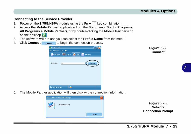
Modules & Options
7
Connecting to the Service Provider1. Power on the 3.75G/HSPA module using the Fn + key combination.2. Access the Mobile Partner application from the Start menu (Start > Programs/
All Programs > Mobile Partner), or by double-clicking the Mobile Partner icon on the desktop .
3. The software will run and you can select the Profile Name from the menu.4. Click Connect to begin the connection process.
5. The Mobile Partner application will then display the connection information.
Figure 7 - 8 Connect
Figure 7 - 9Network
Connection Prompt
3.75G/HSPA Module 7 - 19
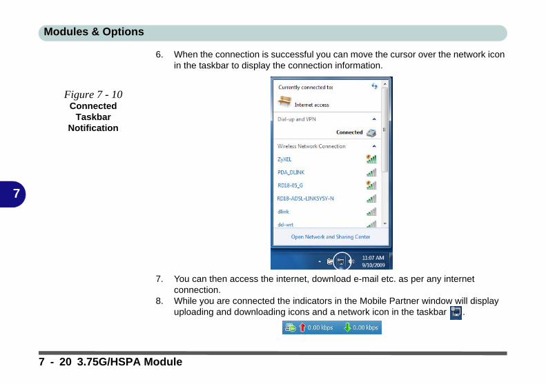
Modules & Options
7
6. When the connection is successful you can move the cursor over the network icon in the taskbar to display the connection information.
7. You can then access the internet, download e-mail etc. as per any internet connection.
8. While you are connected the indicators in the Mobile Partner window will display uploading and downloading icons and a network icon in the taskbar .
Figure 7 - 10Connected
Taskbar Notification
7 - 20 3.75G/HSPA Module

Modules & Options
7
9. To disconnect click the Disconnect icon, or right click the taskbar icon and select Disconnect.
10. The program will disconnect from the service provider.11. The module will still be on, and you will need to press the Fn + key
combination to turn it off.
Figure 7 - 11Disconnect
3.75G/HSPA Module 7 - 21
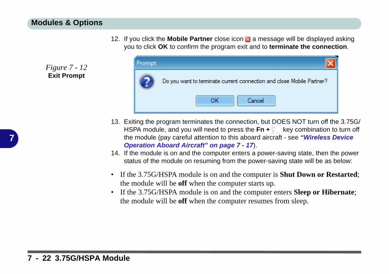
Modules & Options
7
12. If you click the Mobile Partner close icon a message will be displayed asking you to click OK to confirm the program exit and to terminate the connection.
13. Exiting the program terminates the connection, but DOES NOT turn off the 3.75G/HSPA module, and you will need to press the Fn + key combination to turn off the module (pay careful attention to this aboard aircraft - see “Wireless Device Operation Aboard Aircraft” on page 7 - 17).
14. If the module is on and the computer enters a power-saving state, then the power status of the module on resuming from the power-saving state will be as below:
• If the 3.75G/HSPA module is on and the computer is Shut Down or Restarted; the module will be off when the computer starts up.
• If the 3.75G/HSPA module is on and the computer enters Sleep or Hibernate; the module will be off when the computer resumes from sleep.
Figure 7 - 12Exit Prompt
7 - 22 3.75G/HSPA Module
Modules & Options
7
Text Messaging ServiceIn addition to standard internet services you may also send and receive SMS textmessages using the Mobile Partner program, if your service supports SMS.
Reading SMS Messages1. An icon will blink at the bottom of the Mobile Partner interface to notify you of
any new messages received.2. Click the Text icon in the Mobile Partner Interface.3. Select the Local > Inbox or SIM/USIM Card folder and select any message to
read it.4. Right-click the message and choose an option to reply, forward or delete the
message.
Creating and Sending SMS Messages1. Click the Text icon in the Mobile Partner Interface.2. Click the New button .3. Enter the recipient’s number in the Send To... field or click the Send To... button to
select an entry from the phone book, and click OK.4. Type in the message details.5. Click the Send button, Save button to send the message later or Close > Yes to
save in the Draft folder.
For more details on SMS click the Help menu and select Online Help or press F1and select SMS.
3.75G/HSPA Module 7 - 23
Modules & Options
7
Bluetooth ModuleThe operating system’s Bluetooth Devices control panel is used to configure theBluetooth settings in Windows and therefore does not require a driver. Use the Fn+ F12 key combination (see “Function/Hot Key Indicators” on page 1 - 8) to tog-gle power to the Bluetooth module.
Wireless Device
Operation Aboard Aircraft
The use of any portableelectronic transmissiondevices aboard aircraftis usually prohibited.Make sure the mod-ule(s) are OFF if you areusing the computeraboard aircraft.
Use the Fn + F12 keycombination to togglepower to the Bluetoothmodule, and check theLED indicator to see ifthe module is poweredon or not (see Table 1 -2, on page 1 - 8/ Table ,on page 1 - 9).
Bluetooth Data Transfer
Note that the transfer of data between the computer and a Bluetooth enabled device is sup-ported in one direction only (simultaneous data transfer is not supported). Thereforeif you are copying a file from your computer to a Bluetooth enabled device, you will not beable to copy a file from the Bluetooth enabled device to your computer until the file transferprocess from the computer has been completed.
Bluetooth Module & Resuming From Sleep Mode
The Bluetooth module’s default state will be off after resuming from the Sleep power-savingstate. Use the key combination (Fn + F12) to power on the Bluetooth module after the com-puter resumes from Sleep.
7 - 24 Bluetooth Module

Modules & Options
7
Bluetooth Configuration in Windows 7
Setup your Bluetooth Device so the Computer Can Find it1. Turn your Bluetooth device (e.g. PDA, mobile phone etc.) on.2. Make the device discoverable (to do this check your device documentation).
To Turn the Bluetooth Module On1. Press the Fn + F12 key combination to power on the Bluetooth module. 2. A Bluetooth icon will appear in the taskbar.3. You can then do any of the following to access the Bluetooth Devices control
panel.
• Double-click the taskbar icon to access the Bluetooth Devices control panel.
• Click/Right-click the taskbar icon and choose an option from the menu.
Add a Device
Click Start, and clickControl Panel and thenclick Devices andPrinters (Hardwareand Sound). Click Adda device to search forany available Bluetoothdevices.
Figure 7 - 13Bluetooth Devices &
Click Icon Menu
Add a device
Right-Click Taskbar Icon
Bluetooth Module 7 - 25
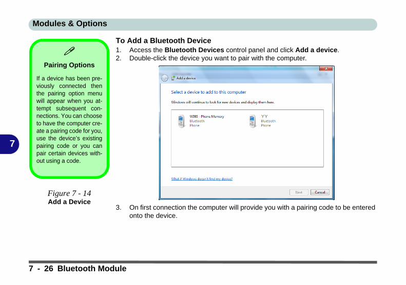
Modules & Options
7
To Add a Bluetooth Device1. Access the Bluetooth Devices control panel and click Add a device.2. Double-click the device you want to pair with the computer.
3. On first connection the computer will provide you with a pairing code to be entered onto the device.
Pairing Options
If a device has been pre-viously connected thenthe pairing option menuwill appear when you at-tempt subsequent con-nections. You can chooseto have the computer cre-ate a pairing code for you,use the device’s existingpairing code or you canpair certain devices with-out using a code.
Figure 7 - 14Add a Device
7 - 26 Bluetooth Module

Modules & Options
7
4. Enter the code into your Bluetooth enabled device and follow any on-screeninstructions to complete the pairing.
5. Windows will check to see if any drivers are required to complete the pairing. 6. Follow any on-screen instructions on the computer if device drivers are required to
be installed.7. Click Close.
Figure 7 - 15Pairing Code
Example
Figure 7 - 16Pairing Complete & Bluetooth Device
Enabled
Pairing Codes
The example outlined here shows a connection toa mobile device. Other devices e.g. computers,may have a slightly different connection proce-dure, and may require you to confirm a pairingcode is correct on both devices. Follow the on-screen instructions to complete the pairing.
Bluetooth Module 7 - 27
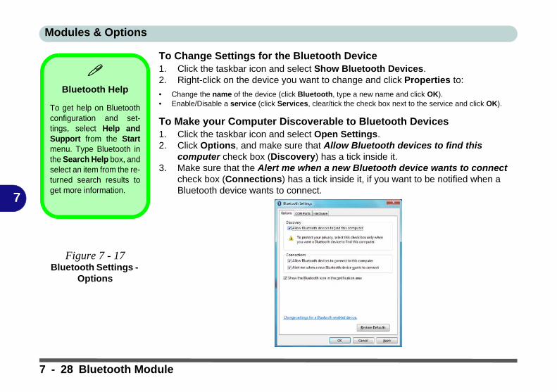
Modules & Options
7
To Change Settings for the Bluetooth Device1. Click the taskbar icon and select Show Bluetooth Devices.2. Right-click on the device you want to change and click Properties to:
• Change the name of the device (click Bluetooth, type a new name and click OK).• Enable/Disable a service (click Services, clear/tick the check box next to the service and click OK).
To Make your Computer Discoverable to Bluetooth Devices1. Click the taskbar icon and select Open Settings.2. Click Options, and make sure that Allow Bluetooth devices to find this
computer check box (Discovery) has a tick inside it.3. Make sure that the Alert me when a new Bluetooth device wants to connect
check box (Connections) has a tick inside it, if you want to be notified when a Bluetooth device wants to connect.
Bluetooth Help
To get help on Bluetoothconfiguration and set-tings, select Help andSupport from the Startmenu. Type Bluetooth inthe Search Help box, andselect an item from the re-turned search results toget more information.
Figure 7 - 17Bluetooth Settings -
Options
7 - 28 Bluetooth Module
Troubleshooting
8
Chapter 8: Troubleshooting
OverviewShould you have any problems with your computer, before consulting your service representative, you may wantto try to solve the problem yourself. This chapter lists some common problems and their possible solutions. Thiscan’t anticipate every problem, but you should check here before you panic. If you don’t find the answer in thesepages, make sure you have followed the instructions carefully and observed the safety precautions in the preface.If all else fails, talk to your service representative. You should also make a record of what happened and whatremedies you tried.
Of course, if something goes wrong, it will happen at the most inconvenient time possible, so you should previewthis section just in case. If, after you’ve tried everything, and the system still won’t cooperate, try turning it offfor a few minutes and then rebooting. You will lose any unsaved data, but it may start working again. Then callyour service representative.
Overview 8 - 1
Troubleshooting
8
Basic Hints and TipsMany of the following may seem obvious but they are often the solution to a problem when your computer ap-pears not to be working.
• Power - Is the computer actually plugged into a working electrical outlet? If plugged into a power strip, make sure it is actually working. Check the LED Indicators (see Table 1 - 3, on page 1 - 9) to see the com-puter’s power status.
• Connections - Check all the cables to make sure that there are no loose connections anywhere.
• Power Savings - Make sure that the system is not in Hibernate or Sleep mode by pressing the keys config-ured in your Power Options (see “Configuring the Power Buttons” on page 3 - 8), the Fn + F4 key combi-nation, or power button to wake-up the system.
• Brightness - Check the brightness of the screen by pressing the Fn + F8 and F9 keys to adjust the bright-ness.
• Display Choice - Press Fn + F7 to make sure the system is not set to “external only” display.
• Boot Drive - Make sure there are no optical media and/or USB storage devices in any connected drive when you start up your machine (this is a common cause of the message “Invalid system disk - Replace the disk, and then press any key” / “Remove disks or other media. Press any key to restart”).
8 - 2 Basic Hints and Tips

Troubleshooting
8
Backup and General Maintenance• Always backup your important data, and keep copies of your OS and programs safe, but close to hand.
Don’t forget to note the serial numbers if you are storing them out of their original cases, e.g. in a CD wal-let.
• Run maintenance programs on your hard disk and OS as often as you can. You may schedule these pro-grams to run at times when you are not using your computer. You can use those that are provided free with your OS, or buy the more powerful dedicated programs to do so.
• Write down your passwords and keep them safe (away from your computer). This is especially important if you choose to use a Supervisor password for the BIOS (see “The Power-On Self Test (POST)” on page 5 - 2).
• Keep copies of vital settings files such as network, dialup settings, mail settings etc.(even if just brief notes).
Warranty
The CPU is not a user serviceable part. Opening this compartment, or accessing the CPU in any way, may violate your war-ranty.
Backup and General Maintenance 8 - 3

Troubleshooting
8
Viruses• Install an Anti-Virus program and keep the definitions file (the file which tells your program which viruses
to look for) up to date. New computer viruses are discovered daily, and some of them may seriously harm your computer and cause you to lose data. Anti-Virus programs are commercially available and the defini-tions file updates are usually downloadable directly from the internet.
• Be careful when opening e-mail from sources you don’t know. Viruses are often triggered from within e-mail attachments so take care when opening any attached file. You can configure most Anti-Virus pro-grams to check all e-mail attachments. Note: You should also beware of files from people you know as the virus may have infected an address book and been automatically forwarded without the person’s knowl-edge.
• Keep a “Bootable CD-ROM/DVD-ROM/USB storage device” (this CD/DVD/USB device provides basic information which allows you to startup your computer) handy. You may refer to your OS’s documentation for instructions on how to make one, and many Anti-Virus programs will also provide such a disk (or at least instructions on how to make one).
8 - 4 Viruses
Troubleshooting
8
Upgrading and Adding New Hardware/Software• Do not be tempted to make changes to your Windows Registry unless you are very sure of what you are
doing, otherwise you will risk severely damaging your system.
• Don’t open your computer or undertake any repair or upgrade work if you are not comfortable with what you are doing.
• Read the documentation. We can assume, since you are reading this that you are looking at the computer’s manual, but what about any new peripheral devices you have just purchased? Many problems are caused by the installation of new hardware and/or software. Always refer to the documentation of any new hardware and/or software, and pay particular attention to files entitled “READ ME” or “READ ME FIRST”.
• When installing a new device always make sure the device is powered on, and in many cases you will need to restart the computer. Always check that all the cables are correctly connected.
• Make sure you have installed the drivers for any new hardware you have installed (latest driver files are usually available to download from vendor’s websites).
Upgrading and Adding New Hardware/Software 8 - 5
Troubleshooting
8
• Thoroughly check any recent changes you made to your system as these changes may affect one or more system components, or software programs. If possible, go back and undo the change you just made and see if the problem still occurs.
• Don’t over complicate things. The less you have to deal with then the easier the source of the problem may be found; Example - if your computer has many devices plugged into its ports, and a number of programs running, then it will be difficult to determine the cause of a problem. Try disconnecting all of the devices and restarting the computer with all the peripheral devices unplugged. A process of elimination (adding and removing devices and restarting where necessary) will often find the source of a problem, although this may be time consuming.
8 - 6 Upgrading and Adding New Hardware/Software

Troubleshooting
8
Problems and Possible Solutions
Problem Possible Cause - Solution
You turned on the power but it doesn’twork.
Battery missing / incorrectly installed. Check the battery bay, make sure thebattery is present and seated properly (the design of the battery only allows it togo in one way). Make sure there’s nothing interfering with the battery contacts.
The battery LED power indicator , isblinking orange.
Low Battery. Plug in the power source. If the computer doesn’t start upimmediately, turn it off then on again.
You are losing battery power too quickly. The system is using too much power. If your OS has a Power Options plan (see“Power Plans” on page 3 - 4) check its settings. You may also be using a USBdevice/external device that is drawing a lot of power.
Actual battery operating time is shorterthan expected.
The battery has not been fully discharged before being recharged. Make surethe battery is fully discharged and recharge it completely before reusing (see“Battery FAQ” on page 3 - 15).
Power Options have been disabled. Go to the Control Panel in Windows andre-enable the options.
A peripheral device is consuming a lot of power. Turn off the unused device tosave power.
Problems and Possible Solutions 8 - 7

Troubleshooting
8
The computer feels too hot. Make sure the computer is properly ventilated and the Vent/Fan intakes are notblocked. If this doesn’t cool it down, put the system into Hibernate mode or turnit off for an hour. Make sure the computer isn’t sitting on a thermal surface (see“Overheating” on page 1 - 10). Make sure you’re using the correct adapter.
Make sure that your notebook is completely powered off before putting it into atravel bag (or any such container). Putting a notebook which is powered on in atravel bag may cause the Vent/Fan intakes to be blocked.
Nothing appears on screen. The system is in a power saving mode. Toggle the sleep/resume keycombination, Fn + F4 (see “Resuming Operation” on page 3 - 9).
The screen controls need to be adjusted. Toggle the screen control keycombinations Fn + F8/F9. If you’re connected to an external monitor, make sureit’s plugged in and turned on. You should also check the monitor’s ownbrightness and contrast controls.
The computer is set for a different display. Toggle the screen display keycombination, Fn + F7. If an external monitor is connected, turn it on.
The screen saver is activated. Press any key or touch the TouchPad.
No image appears on the externalmonitor I have plugged in and poweredon.
You haven’t installed the video driver and configured it appropriately from theControl Panel. See “Display Devices & Options” on page B - 5 forinstructions on installing and configuring the video driver.
Problem Possible Cause - Solution
8 - 8 Problems and Possible Solutions

Troubleshooting
8
You forget the boot password. If you forget the password, you may have to discharge the battery of the CMOS.Contact your service representative for help.
The sound cannot be heard or the volumeis very low.
The volume might be set too low. Check the volume control in the VolumeControl Panel in the Windows taskbar, or use the key combination Fn + F5 andF6 (see “Function/Hot Key Indicators” on page 1 - 8) to adjust.
Audio cannot be recorded from the built-in or external microphone.
The audio recording options need to be configured from the VIA HD AudioDeck. See “Audio Features” on page 2 - 10 for configuration information, and“PC Camera Audio Setup” on page 7 - 10 for information on recording audiofrom the PC Camera.
Unwelcome numbers appear whentyping.
Check that Num Lock is not turned ON.
Problem Possible Cause - Solution
Password Warning
If you choose to set a boot password, NEVER forget your password. The consequences of this could be serious. If you cannotremember your boot password you must contact your vendor and you may lose all of the information on your hard disk.
Problems and Possible Solutions 8 - 9
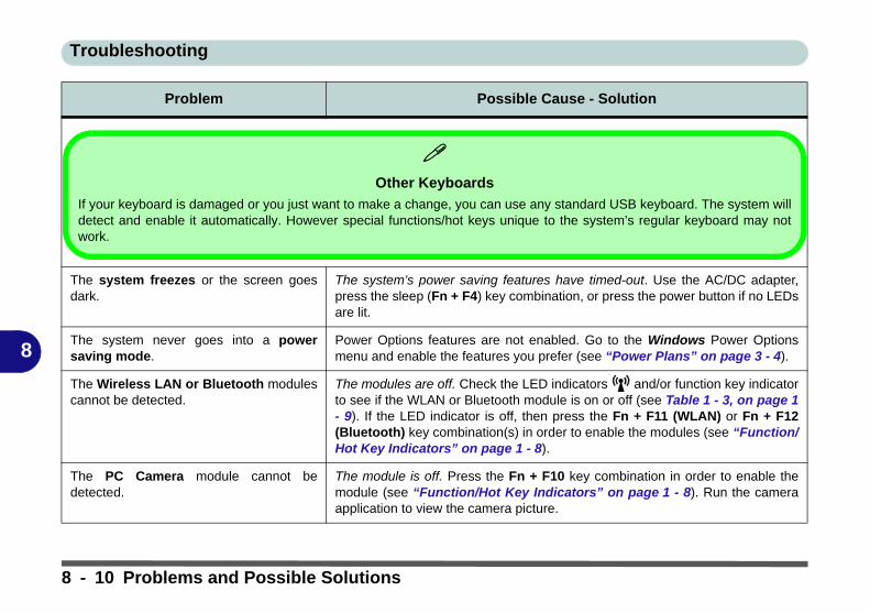
Troubleshooting
8
The system freezes or the screen goesdark.
The system’s power saving features have timed-out. Use the AC/DC adapter,press the sleep (Fn + F4) key combination, or press the power button if no LEDsare lit.
The system never goes into a powersaving mode.
Power Options features are not enabled. Go to the Windows Power Optionsmenu and enable the features you prefer (see “Power Plans” on page 3 - 4).
The Wireless LAN or Bluetooth modulescannot be detected.
The modules are off. Check the LED indicators and/or function key indicatorto see if the WLAN or Bluetooth module is on or off (see Table 1 - 3, on page 1- 9). If the LED indicator is off, then press the Fn + F11 (WLAN) or Fn + F12(Bluetooth) key combination(s) in order to enable the modules (see “Function/Hot Key Indicators” on page 1 - 8).
The PC Camera module cannot bedetected.
The module is off. Press the Fn + F10 key combination in order to enable themodule (see “Function/Hot Key Indicators” on page 1 - 8). Run the cameraapplication to view the camera picture.
Problem Possible Cause - Solution
Other Keyboards
If your keyboard is damaged or you just want to make a change, you can use any standard USB keyboard. The system willdetect and enable it automatically. However special functions/hot keys unique to the system’s regular keyboard may notwork.
8 - 10 Problems and Possible Solutions
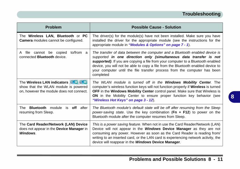
Troubleshooting
8
The Wireless LAN, Bluetooth or PCCamera modules cannot be configured.
The driver(s) for the module(s) have not been installed. Make sure you haveinstalled the driver for the appropriate module (see the instructions for theappropriate module in “Modules & Options” on page 7 - 1).
A file cannot be copied to/from aconnected Bluetooth device.
The transfer of data between the computer and a Bluetooth enabled device issupported in one direction only (simultaneous data transfer is notsupported). If you are copying a file from your computer to a Bluetooth enableddevice, you will not be able to copy a file from the Bluetooth enabled device toyour computer until the file transfer process from the computer has beencompleted
The Wireless LAN indicators show that the WLAN module is poweredon, however the module does not connect.
The WLAN module is turned off in the Windows Mobility Center. Thecomputer’s wireless function keys will not function properly if Wireless is turnedOFF in the Windows Mobility Center control panel. Make sure that Wireless isON in the Mobility Center to ensure proper function key behavior (see“Wireless Hot Keys” on page 3 - 12).
The Bluetooth module is off afterresuming from Sleep.
The Bluetooth module’s default state will be off after resuming from the Sleeppower-saving state. Use the key combination (Fn + F12) to power on theBluetooth module after the computer resumes from Sleep.
The Card Reader/Network (LAN) Devicedoes not appear in the Device Manager inWindows.
This is a power saving feature. When not in use the Card Reader/Network (LAN)Device will not appear in the Windows Device Manager as they are notconsuming any power. However as soon as the Card Reader is reading from/writing to an inserted card, or the LAN card is experiencing network activity, thedevice will reappear in the Windows Device Manager.
Problem Possible Cause - Solution
Problems and Possible Solutions 8 - 11

Troubleshooting
8
An external display is attached, but cannotbe detected.
External display detection has been disabled in the BIOS. Check that detectingexternal CRTs has not been disabled in the BIOS. See “Detect External CRT(Advanced Menu > Advanced Chipset Control)” on page 5 - 8.
Problem Possible Cause - Solution
8 - 12 Problems and Possible Solutions

Troubleshooting
8
Bluetooth Connection ProblemsIf you are experiencing problems connecting to some Bluetooth devices (in particular certain mobile phones andheadsets) it maybe necessary to download and install the Windows Mobile Device Center software (for Win-dows Vista and Windows 7). Go to the Microsoft website and search for the Microsoft Windows Device CenterDriver for Windows Vista (64-bit or 32-bit) and Windows 7 (64-bit or 32-bit), and then download the driver.
1. Install the Microsoft Windows Device Center Driver as appropriate for your operating system.2. Windows Vista will automatically configure the driver for you, however Windows 7 requires further configuration.3. Make sure the Bluetooth device is powered on.4. Go the Windows 7 control panel and double-click Device Manager (Hardware and Sound > Devices and
Printers).5. Bluetooth Peripheral Device(s) will be listed under Other Devices (note this will only be listed if you have
connected, or tried to connect to, a Bluetooth device previously).
Figure 8 - 1 - Device Manager
Bluetooth Peripheral Devices
You will need to repeat the procedurelisted here for all Bluetooth Peripher-al Devices listed under Other Devicesi.e. until there are no more BluetoothPeripheral Devices listed under thismenu heading.
Bluetooth Connection Problems 8 - 13
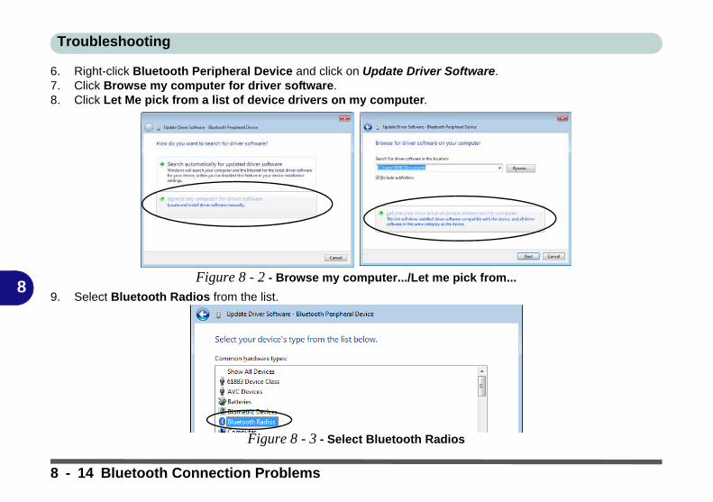
Troubleshooting
8
6. Right-click Bluetooth Peripheral Device and click on Update Driver Software.7. Click Browse my computer for driver software.8. Click Let Me pick from a list of device drivers on my computer.
Figure 8 - 2 - Browse my computer.../Let me pick from...
9. Select Bluetooth Radios from the list.
Figure 8 - 3 - Select Bluetooth Radios
8 - 14 Bluetooth Connection Problems
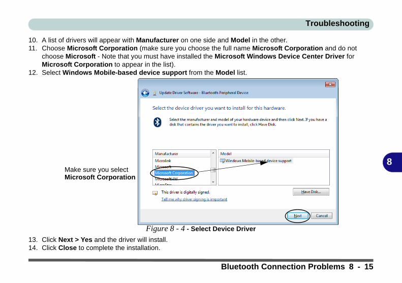
Troubleshooting
8
10. A list of drivers will appear with Manufacturer on one side and Model in the other. 11. Choose Microsoft Corporation (make sure you choose the full name Microsoft Corporation and do not
choose Microsoft - Note that you must have installed the Microsoft Windows Device Center Driver for Microsoft Corporation to appear in the list).
12. Select Windows Mobile-based device support from the Model list.
Figure 8 - 4 - Select Device Driver
13. Click Next > Yes and the driver will install.14. Click Close to complete the installation.
Make sure you selectMicrosoft Corporation
Bluetooth Connection Problems 8 - 15

Troubleshooting
8
15. The Device Manager should now display the Windows Mobile-based device support under Bluetooth Radios.
16. You will need to repeat the process for any other Bluetooth Peripheral Devices listed under Other Devices.
Figure 8 - 5 - Device Manager - Bluetooth Radio
8 - 16 Bluetooth Connection Problems

Interface (Ports & Jacks)
A
Appendix A: Interface (Ports & Jacks)
OverviewThe following chapter will give a quick description of the interface (ports & jacks) which allow your computerto communicate with external devices, connect to the internet etc.
Interface (Ports & Jacks) A - 1
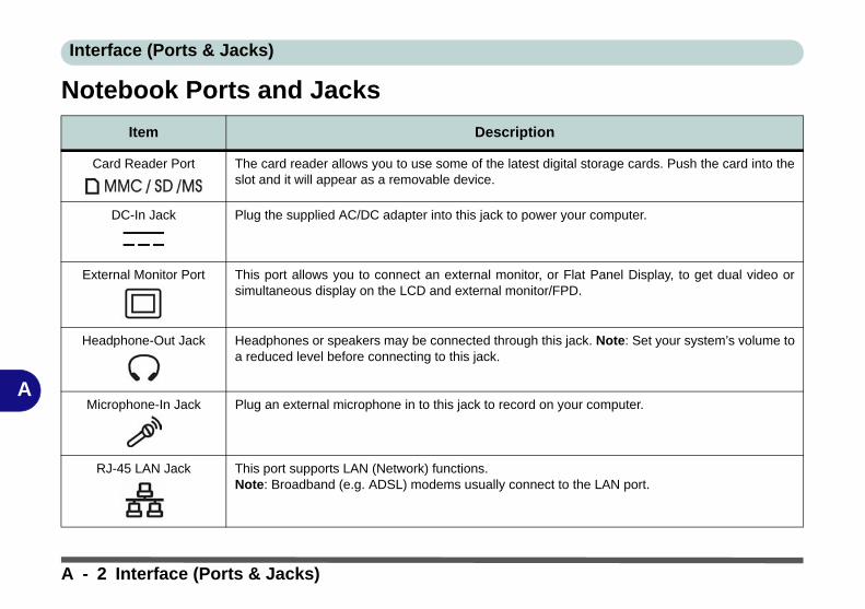
Interface (Ports & Jacks)
A
Notebook Ports and Jacks
Item Description
Card Reader Port The card reader allows you to use some of the latest digital storage cards. Push the card into theslot and it will appear as a removable device.
DC-In Jack Plug the supplied AC/DC adapter into this jack to power your computer.
External Monitor Port This port allows you to connect an external monitor, or Flat Panel Display, to get dual video orsimultaneous display on the LCD and external monitor/FPD.
Headphone-Out Jack Headphones or speakers may be connected through this jack. Note: Set your system’s volume toa reduced level before connecting to this jack.
Microphone-In Jack Plug an external microphone in to this jack to record on your computer.
RJ-45 LAN Jack This port supports LAN (Network) functions.Note: Broadband (e.g. ADSL) modems usually connect to the LAN port.
A - 2 Interface (Ports & Jacks)
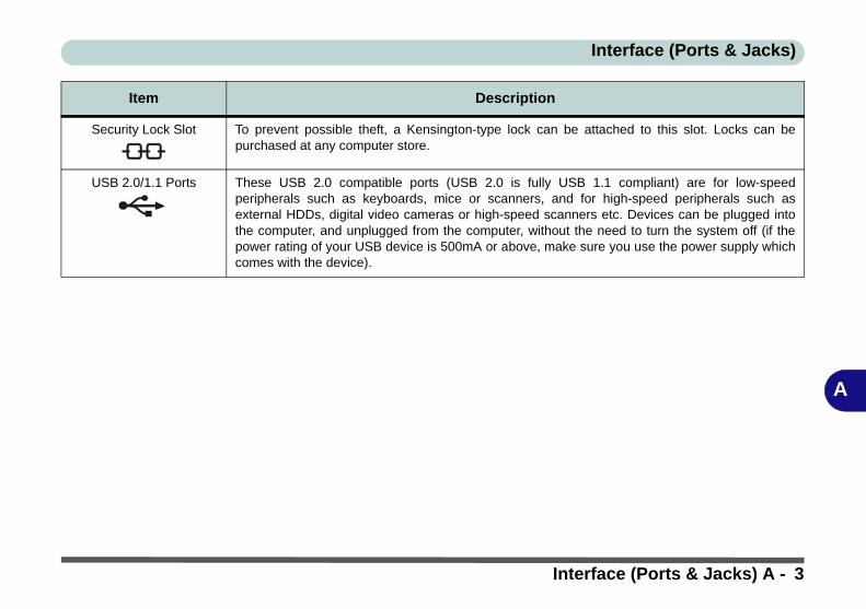
Interface (Ports & Jacks)
A
Security Lock Slot To prevent possible theft, a Kensington-type lock can be attached to this slot. Locks can bepurchased at any computer store.
USB 2.0/1.1 Ports These USB 2.0 compatible ports (USB 2.0 is fully USB 1.1 compliant) are for low-speedperipherals such as keyboards, mice or scanners, and for high-speed peripherals such asexternal HDDs, digital video cameras or high-speed scanners etc. Devices can be plugged intothe computer, and unplugged from the computer, without the need to turn the system off (if thepower rating of your USB device is 500mA or above, make sure you use the power supply whichcomes with the device).
Item Description
Interface (Ports & Jacks) A - 3

Interface (Ports & Jacks)
A
A - 4

B
Appendix B: Intel Video Driver ControlsThe basic settings for configuring the LCD are outlined in “Video Features” onpage 1 - 15.
Intel Video Driver InstallationMake sure you install all the drivers in the order indicated in Table 4 - 1, on page 4 - 3.
Video1. Insert the Device Drivers & Utilities + User’s Manual disc into your exter-
nal optical device drive.2. Click 2.Install VGA Driver > Yes.3. Click Next > Yes > Next > Next.4. Click Finish to restart the computer.
Dynamic Video Memory TechnologyIntel® DVMT automatically and dynamically allocates as much (up to 384MB) sys-tem memory (RAM) as needed to the video system (the video driver must be in-stalled). DVMT returns whatever memory is no longer needed to the operatingsystem.
DVMT Notes
DVMT is not local videomemory.
DVMT is not user-con-figurable.
DVMT will not functionin MS-DOS. DOS usesthe legacy memory indi-cated.
Intel Video Driver Installation B - 1

B
Intel GMA Driver for MobileAdvanced video configuration options are provided by the Intel(R) Graphics Me-dia Accelerator Driver for Mobile. To access the Intel(R) Graphics Media Accel-erator Driver for mobile control panel:
1. Click Advanced settings in the Screen Resolution control panel in Windows.2. Click the Intel(R)... tab and click Graphics Properties (button).OR3. Right-click the desktop and select Graphics Properties from the menu.OR4. Double-click the Intel(R) GMA Driver for Mobile control panel in Windows.
Taskbar Icon
You can also access thecontroller propertiesfrom the taskbar. Clickon the icon to bringup the menu and scrollto Graphics Proper-ties.
If you cannot see thetray icon go to the In-tel(R) Graphics MediaAccelerator Driver tab(in the Screen Resolu-tion > Advanced op-tions) and click the“Show Tray Icon” tick-box.
Figure B - 1Intel GMA Control
Panels Show Tray Icon
B - 2 Intel GMA Driver for Mobile
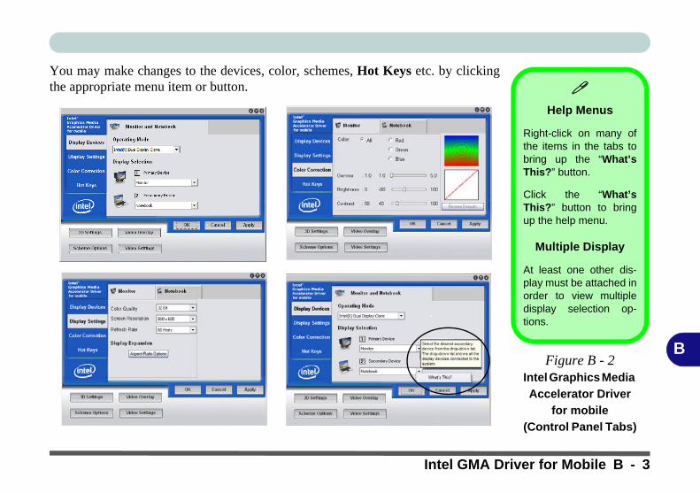
B
You may make changes to the devices, color, schemes, Hot Keys etc. by clickingthe appropriate menu item or button.
Help Menus
Right-click on many ofthe items in the tabs tobring up the “What’sThis?” button.
Click the “What’sThis?” button to bringup the help menu.
Multiple Display
At least one other dis-play must be attached inorder to view multipledisplay selection op-tions.
Figure B - 2Intel Graphics Media
Accelerator Driver
for mobile
(Control Panel Tabs)
Intel GMA Driver for Mobile B - 3

B
Scheme OptionsUse Scheme Options to configure quick settings for applications which require spe-cific resolution and color settings in order to run properly e.g. games, multimediaprograms. To set the scheme options:
1. Go to the GMA for mobile control panel (see page B - 2).2. Configure your display configuration, resolution etc. as per your requirements,
from Display Devices (tab).3. Click on Scheme Options (button).4. Type a name for the scheme then click Save.5. If you want to automatically launch an application when running the scheme click
on Browse (button).6. Browse to the executable file for the application you want to set the scheme for
(see sidebar), and click Open to select it.7. Click Save to save the settings (you can click in the “Restore the display settings
after exiting this application” box to return to your original settings when you exitthe program).
8. Click OK to exit the program.9. You can run the scheme by clicking the taskbar icon and selecting the scheme
from Select Scheme.
Application.exe
You will need to locatethe actual applicationexecutable (.exe) file,not just the shortcut. Tofind the application right-click its shortcut on thedesktop click Proper-ties. Click the Shortcut(tab) and see where theexecutable file is locatedby clicking the Find Tar-get (button). Note the lo-cation and you will thenbe able to browse to thisfile.
Figure B - 3Select Scheme
B - 4 Intel GMA Driver for Mobile

B
Display Devices & OptionsBesides the built-in LCD, you can also use an external VGA monitor (CRT) or ex-ternal Flat Panel Display as your display device. A VGA monitor/Flat Panel Dis-play connects to the external monitor port. The following display modes areavailable (if you are unable to detect an attached display, check that detecting exter-nal CRTs has not been disabled in the BIOS - see “Detect External CRT (AdvancedMenu > Advanced Chipset Control)” on page 5 - 8).
Intel Display Mode Description
Single Display One of the connected displays is used as the display device
Multiple Display - Intel(R) Dual Display Clone
Both connected displays output the same view and may be configured independently
Multiple Display - Extended Desktop
Both connected displays are treated as separate devices, and act as a virtual desktop
Function Key Combination
You can use the Fn + F7key combination to tog-gle through the displayoptions:
• Notebook Only• External Display Only• Notebook + External
Display
Make sure you give thedisplays enough time torefresh.
Table B - 1Display Modes
Attaching Displays
When you first attach an external display you may find that the desktop does not occupythe full screen area. Use either the display’s auto adjust/configure controls, or the Intel(R)GMA Driver for Mobile control panel to configure the full screen display.
Intel GMA Driver for Mobile B - 5
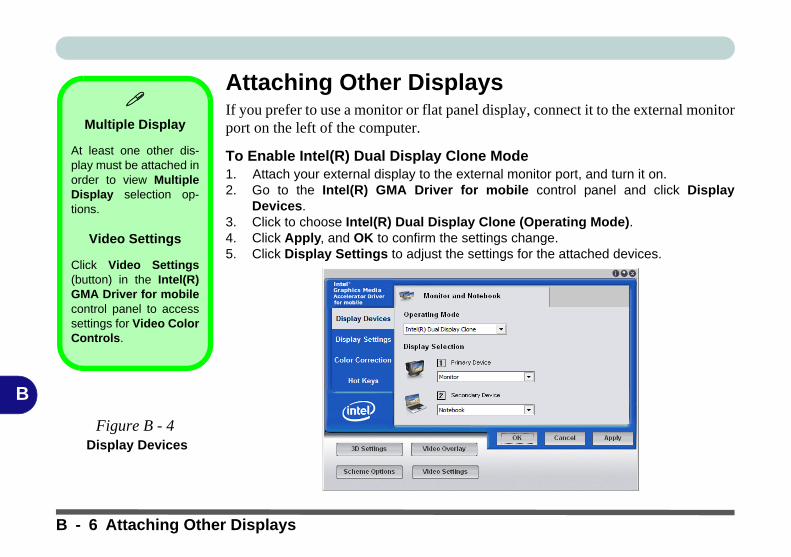
B
Attaching Other DisplaysIf you prefer to use a monitor or flat panel display, connect it to the external monitorport on the left of the computer.
To Enable Intel(R) Dual Display Clone Mode1. Attach your external display to the external monitor port, and turn it on.2. Go to the Intel(R) GMA Driver for mobile control panel and click Display
Devices.3. Click to choose Intel(R) Dual Display Clone (Operating Mode).4. Click Apply, and OK to confirm the settings change.5. Click Display Settings to adjust the settings for the attached devices.
Multiple Display
At least one other dis-play must be attached inorder to view MultipleDisplay selection op-tions.
Video Settings
Click Video Settings(button) in the Intel(R)GMA Driver for mobilecontrol panel to accesssettings for Video ColorControls.
Figure B - 4 Display Devices
B - 6 Attaching Other Displays
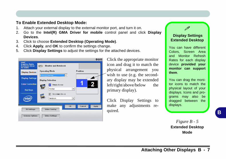
B
To Enable Extended Desktop Mode:1. Attach your external display to the external monitor port, and turn it on.2. Go to the Intel(R) GMA Driver for mobile control panel and click Display
Devices.3. Click to choose Extended Desktop (Operating Mode).4. Click Apply, and OK to confirm the settings change.5. Click Display Settings to adjust the settings for the attached devices.
Display Settings
Extended Desktop
You can have differentColors, Screen Areaand Monitor RefreshRates for each displaydevice provided yourmonitor can supportthem.
You can drag the moni-tor icons to match thephysical layout of yourdisplays. Icons and pro-grams may also bedragged between thedisplays.
Figure B - 5
Extended Desktop
Mode
Click the appropriate monitoricon and drag it to match thephysical arrangement youwish to use (e.g. the second-ary display may be extendedleft/right/above/below theprimary display).
Click Display Settings tomake any adjustments re-quired.
Attaching Other Displays B - 7

B
Attaching Other DisplaysConfiguring an External Display in Windows 71. Attach your external display to the external monitor port and turn it on.2. Go to the Screen resolution control panel.3. Click the Detect button.4. The computer will then detect any attached displays.
Function Key Combination
You can use the Fn +F7 key combination totoggle through the dis-play options:
• Notebook Only• External Display
Only• Notebook + External
Display
Make sure you give thedisplays enough timeto refresh.
Figure B - 6Screen Resolution
Multiple Displays
(Win 7)
B - 8 Attaching Other Displays
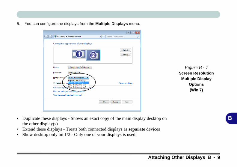
B
5. You can configure the displays from the Multiple Displays menu.
• Duplicate these displays - Shows an exact copy of the main display desktop on the other display(s)
• Extend these displays - Treats both connected displays as separate devices• Show desktop only on 1/2 - Only one of your displays is used.
Figure B - 7
Screen Resolution
Multiple Display
Options
(Win 7)
Attaching Other Displays B - 9
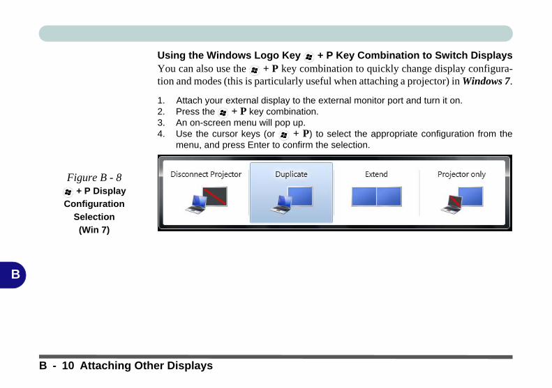
B
Using the Windows Logo Key + P Key Combination to Switch DisplaysYou can also use the + P key combination to quickly change display configura-tion and modes (this is particularly useful when attaching a projector) in Windows 7.
1. Attach your external display to the external monitor port and turn it on.2. Press the + P key combination.3. An on-screen menu will pop up.4. Use the cursor keys (or + P) to select the appropriate configuration from the
menu, and press Enter to confirm the selection.
Figure B - 8 + P Display
Configuration
Selection
(Win 7)
B - 10 Attaching Other Displays
Specifications
C
Appendix C: Specifications
Latest Specification Information
The specifications listed in this Appendix are correct at the time of going to press. Certain items (particularly processor types/speeds and CD/DVD device types) may be changed, delayed or updated due to the manufacturer's release schedule. Checkwith your service center for details.
Specifications C - 1
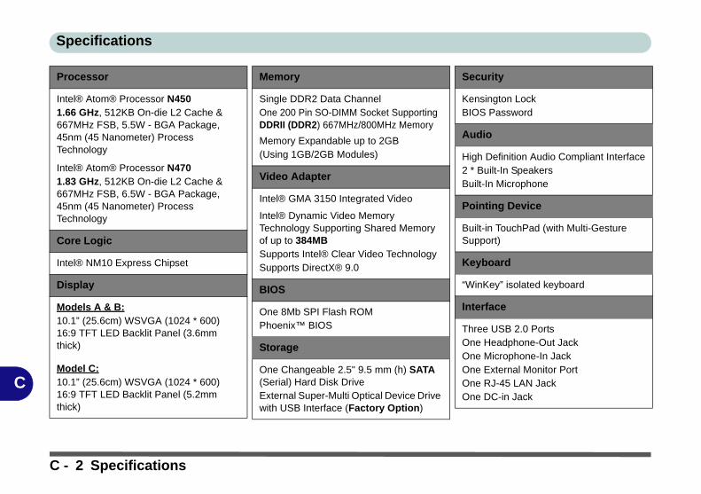
Specifications
C
Processor
Intel® Atom® Processor N4501.66 GHz, 512KB On-die L2 Cache & 667MHz FSB, 5.5W - BGA Package, 45nm (45 Nanometer) Process Technology
Intel® Atom® Processor N4701.83 GHz, 512KB On-die L2 Cache & 667MHz FSB, 6.5W - BGA Package, 45nm (45 Nanometer) Process Technology
Core Logic
Intel® NM10 Express Chipset
Display
Models A & B:10.1” (25.6cm) WSVGA (1024 * 600) 16:9 TFT LED Backlit Panel (3.6mm thick)
Model C:10.1” (25.6cm) WSVGA (1024 * 600) 16:9 TFT LED Backlit Panel (5.2mm thick)
Memory
Single DDR2 Data ChannelOne 200 Pin SO-DIMM Socket Supporting DDRII (DDR2) 667MHz/800MHz Memory
Memory Expandable up to 2GB (Using 1GB/2GB Modules)
Video Adapter
Intel® GMA 3150 Integrated Video
Intel® Dynamic Video Memory Technology Supporting Shared Memory of up to 384MBSupports Intel® Clear Video TechnologySupports DirectX® 9.0
BIOS
One 8Mb SPI Flash ROMPhoenix™ BIOS
Storage
One Changeable 2.5" 9.5 mm (h) SATA (Serial) Hard Disk DriveExternal Super-Multi Optical Device Drive with USB Interface (Factory Option)
Security
Kensington LockBIOS Password
Audio
High Definition Audio Compliant Interface2 * Built-In SpeakersBuilt-In Microphone
Pointing Device
Built-in TouchPad (with Multi-Gesture Support)
Keyboard
“WinKey” isolated keyboard
Interface
Three USB 2.0 PortsOne Headphone-Out JackOne Microphone-In JackOne External Monitor PortOne RJ-45 LAN JackOne DC-in Jack
C - 2 Specifications

Specifications
C
Communication
10Mb/100Mb Base-TX Ethernet LAN
802.11b/g/n Wireless LAN Half Mini-Card Module (Factory Option)
UMTS/HSPDA-based 3.75G/HSPA (Half Mini-Card) Module (Factory Option)
Bluetooth v2.1 + EDR Module (Factory Option)
300K Pixel USB PC Camera Module
1.3M Pixel USB PC Camera Module (Factory Option)
Operating System
Windows® 7 (32-bit Only)
Card Reader
Embedded 3-in-1 Card Reader - MMC/ RS MMC- SD/ Mini SD / SDHC/ SDXC compatible - MS/ MS Pro/ MS Duo) Note: RS MMC/ Mini SD/ MS Duo Cards require a PC adapter
Slot
Two Mini-Card Slots (USB & PCIe)Slot 1: for WLAN 802.11 b/g/n Module (Half Mini-Card) with PCIe Interface
Slot 2: for UMTS/HSPDA-based 3.75G/HSPA Module (Half Mini-Card) with USB Interface
Power Management
Wake On LANWake On USBEnergy Star 5.0 Compliant
Power
Full Range AC/DC AdapterAC Input: 100 - 240V, 50 - 60HzDC Output: 19V, 1.58A (30 Watts)
Design Feature
Magic Of Film Art II Changeable LCD Back Covers (Factory Option for Model B Computers)
IMR (Injected Molded Resin) LCD Back Covers (Factory Option for Model C Computers)
Battery
Removable 3 Cell Smart Lithium-Ion Battery Pack 24.42WH
Removable 6 Cell Smart Lithium-Ion Battery Pack 48.84WH (Factory Option)
Environmental Spec
Temperature Operating: 5°C - 35°CNon-Operating: -20°C - 60°CRelative HumidityOperating: 20% - 80%Non-Operating: 10% - 90%
Dimensions & Weight
Model A:266mm (w) * 185mm (d) * 18.5 - 25.4mm (h)0.94kg with 3 Cell Battery
Model B:266mm (w) * 185mm (d) * 18.5 - 26.6mm (h)0.97kg with 3 Cell Battery
Model C:266mm (w) * 185mm (d) * 19.7 - 27.1mm (h)0.93kg with 3 Cell Battery
Specifications C - 3

Specifications
C
C - 4