v12 user guide - squarespace · v12 user guide isys - the imaging ... attention: the v12 plotter...
TRANSCRIPT

www.isys-group.com
V12User Guide
iSys - The Imaging Systems Group Inc. © Copyright 2010 Rev 003

2
COPYRIGHT NOTICE This document is copyrighted by The Imaging Systems Group 2010. No part of this publication may be reproduced, transmitted, transcribed, or stored in a retrieval system of any kind without prior written permission of The Imaging Systems Group. TRADEMARKS Centronics is a U.S. registered trademark of Centronics Data Computer Corporation. Versatec is a registered trademark of Versatec Corporation. DISCLAIMER The Imaging Systems Group makes no warranties as to the accuracy, validity or fitness for use of the contents of this manual. The Imaging Systems Group reserves the right to revise the information in this manual at any time without notice. ATTENTION: The V12 plotter generates, uses and can radiate radio frequency energy and, if not installed and used in accordance with the instruction manual, may cause interference to radio communications. It has been designed to comply with the requirements for Class A computing devices pursuant to Sub-part J of Part 15 of FCC Rules, which are designed to provide reasonable protection against such interference when operated in a commercial environment. Operation of this equipment in a residential area is likely to cause interference in which case, the user, at their own expense will be required to take whatever measures may be required to correct the interference. LIMITATION OF LIABILITY The Imaging Systems Group’s total liability to the purchaser, or to any third party, for damages from any and all causes whatsoever, regardless of the form of action, whether in contract or in tort, including negligence, and any infringement of proprietary rights or any misappropriation or unlawful use of any proprietary rights or property of any third party shall, in the aggregate, be limited to purchase price actually paid by the purchaser for the product relating to the damages. The limitation of liability provisions of this agreement reflect an informed voluntary allocation of the risks (known and unknown) that may exist in connection with the provisions of the goods and services provided hereunder by The Imaging Systems Group, and that such voluntary risk allocation represents a fundamental part of the agreement reached between The Imaging Systems Group and the purchaser. The Imaging Systems Group shall not be liable for any special, direct or indirect, incidental, consequential, exemplary, punitive or any similar or other damages of any nature suffered by the purchaser whatsoever including, without limitation, loss of use or lack of availability of the purchaser facilities, including its computer resources and any stored data, loss of profits or revenue, or other commercial loss, or any claim for contribution or indemnity in respect of any claims against the purchaser, regardless of whether The Imaging Systems Group has been advised of the possibility of such damages. The Imaging Systems Group Inc. 911 28 Street NE Calgary, Alberta T2A-7X1 Canada Phone (403) 204-5200 Fax: (403) 204-1971 E-mail: [email protected] http://www.isys-group.com
3
CONTENTS INTRODUCTION ........................................................................................................................................ 8
GENERAL DESCRIPTION ................................................................................................................... 8
1.1 MEDIA DESCRIPTION ............................................................................................................. 8
1.3 ABOUT THIS MANUAL ................................................................................................................. 8
SPECIFICATIONS ..................................................................................................................................... 9
2.1 FUNCTIONAL .................................................................................................................................. 9
Operation ............................................................................................................................................ 9
Media ................................................................................................................................................. 10
Thermal printhead .......................................................................................................................... 10
Transport .......................................................................................................................................... 10
2.2 ELECTRICAL ................................................................................................................................. 10
Interface ............................................................................................................................................ 10
Power consumption ...................................................................................................................... 10
Power requirements ...................................................................................................................... 11
2.3 PHYSICAL ...................................................................................................................................... 11
2.4 ENVIRONMENTAL ....................................................................................................................... 11
Temperature .................................................................................................................................... 11
Other .................................................................................................................................................. 11
INSTALLATION ....................................................................................................................................... 12
3.1 UNPACKING .................................................................................................................................. 12
3.2 MOUNTING AND POSITIONING ............................................................................................... 13
3.3 INTERFACE SETUP ..................................................................................................................... 13
Changing the interface line setting ........................................................................................... 13
3.4 MEDIA INSTALLATION ............................................................................................................... 14
Installing rolled paper ................................................................................................................... 14
Installing fan-fold paper ............................................................................................................... 16
Installing and using film ............................................................................................................... 17
Installing the fan-fold feeder tray ............................................................................................... 17
OPERATION ............................................................................................................................................. 18
4.1 POWER SUPPLY PRECAUTIONS ............................................................................................ 18
4.2 USING THE CONTROL PANEL ................................................................................................. 18
4.3 CONTROL PANEL FUNCTIONS AND SETTINGS ................................................................ 19

4
Changing function settings: ........................................................................................................ 19
Test mode......................................................................................................................................... 20
Contrast ............................................................................................................................................ 20
Speed ................................................................................................................................................ 20
Media ................................................................................................................................................. 21
Scaling .............................................................................................................................................. 21
Beeper ............................................................................................................................................... 21
Form feed length ............................................................................................................................ 22
Scan width ....................................................................................................................................... 22
Vertical resolution .......................................................................................................................... 23
TOF display descriptions ............................................................................................................. 23
THEORY OF OPERATION .................................................................................................................... 25
5.1 INTRODUCTION ........................................................................................................................... 25
5.2 PLOTTER FUNCTIONS AND FEATURES............................................................................... 25
Power supply ................................................................................................................................... 25
MAINTENANCE AND REPAIR ............................................................................................................. 27
6.1 MAINTENANCE GUIDELINES ................................................................................................... 27
6.2 REGULAR MAINTENANCE ........................................................................................................ 28
Cleaning the thermal printhead .................................................................................................. 28
Cleaning the platen roller ............................................................................................................. 28
Cleaning the Top of Form/Media out sensors ........................................................................ 29
6.3 REPAIR PROCEDURES.............................................................................................................. 29
Tools .................................................................................................................................................. 29
Opening the plotter lid .................................................................................................................. 29
Removing the top cover ............................................................................................................... 29
Opening the back panel ............................................................................................................... 29
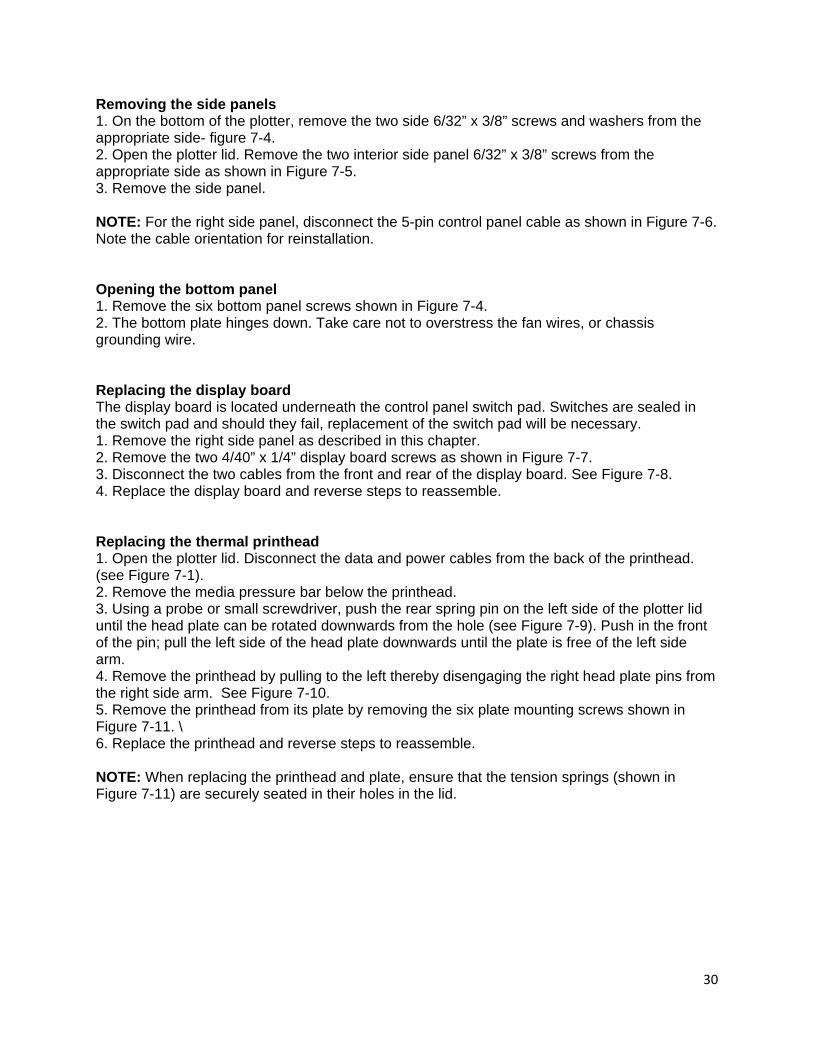
Removing the side panels ........................................................................................................... 30
Opening the bottom panel ........................................................................................................... 30
Replacing the display board ....................................................................................................... 30
Replacing the thermal printhead ................................................................................................ 30
Adjusting the printhead ................................................................................................................ 31
Replacing the printhead data cable .......................................................................................... 31
Replacing the drive belt ............................................................................................................... 31
5
Replacing the gears ....................................................................................................................... 32
Replacing the stepper motor ...................................................................................................... 32
Replacing the platen roller and bearings ................................................................................ 32
Measuring and adjusting 5 V power supply voltage ............................................................. 32
Replacing the 5 V power supply ................................................................................................ 33
Replacing the Top of Form (TOF) sensor board .................................................................... 33
Adjusting the top of form sensor ............................................................................................... 34
Replacing the rear cooling fan ................................................................................................... 35
Replacing the bottom cooling fan ............................................................................................. 35
Measuring and adjusting 24 Volt power supply voltage ..................................................... 35
Replacing the 24 Volt power supply ......................................................................................... 36
Replacing the main board ............................................................................................................ 36
Replacing the capacitor ............................................................................................................... 36
Adjusting the latch pins ............................................................................................................... 37
Replacing the power switch ........................................................................................................ 37
Replacing the AC receptacle ....................................................................................................... 37
Replacing the fuse ......................................................................................................................... 38
FIGURES ................................................................................................................................................... 39
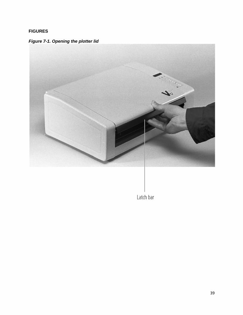
Figure 7-1. Opening the plotter lid ................................................................................................. 39
Figure 7-2. Back panel .................................................................................................................... 40
Figure 7-3. Back panel (open) ........................................................................................................ 41
Figure 7-4. Bottom view .................................................................................................................. 41
Figure 7-5. Interior side screws ...................................................................................................... 42
Figure 7-6. Control panel ................................................................................................................ 43
Figure 7-7. Display board ................................................................................................................ 43
Figure 7-8. Right side (display board removed) .......................................................................... 44
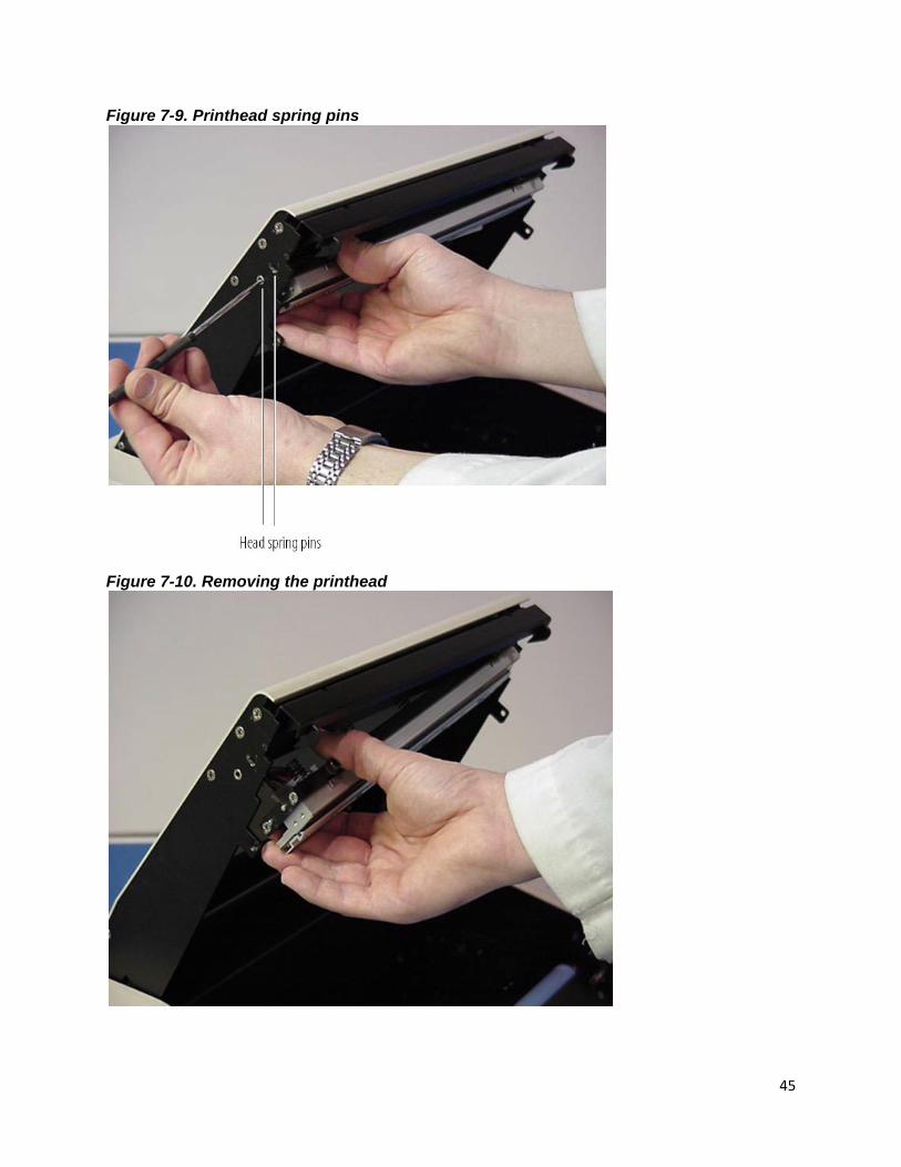
Figure 7-9. Printhead spring pins ................................................................................................... 45
Figure 7-10. Removing the printhead ............................................................................................ 45
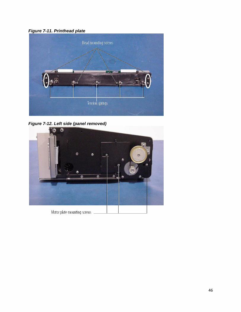
Figure 7-11. Printhead plate ........................................................................................................... 46
Figure 7-12. Left side (panel removed) ......................................................................................... 46
Figure 7-13. Gears and belt ............................................................................................................ 47
Figure 7-14. Bottom view (panels removed) ................................................................................ 47
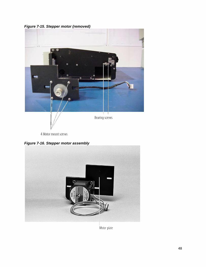
Figure 7-15. Stepper motor (removed) ......................................................................................... 48

6
Figure 7-16. Stepper motor assembly ........................................................................................... 48
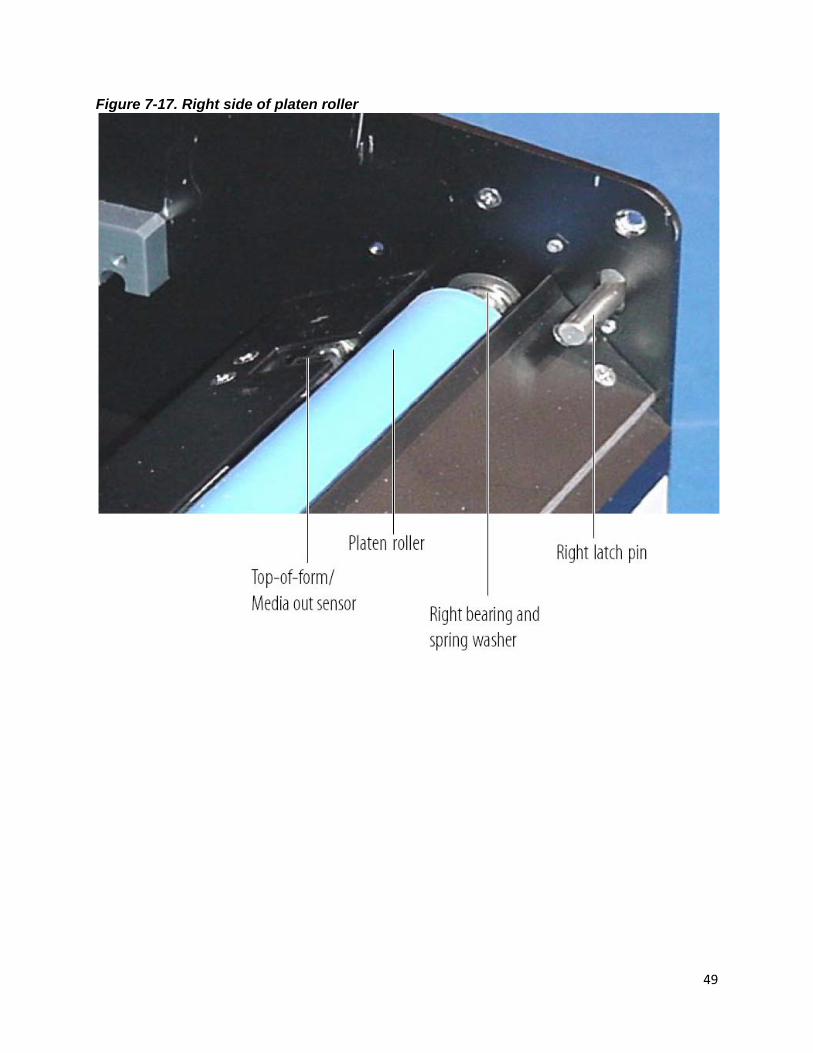
Figure 7-17. Right side of platen roller .......................................................................................... 49
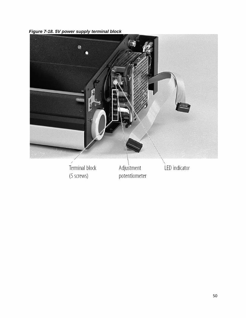
Figure 7-18. 5V power supply terminal block ............................................................................... 50
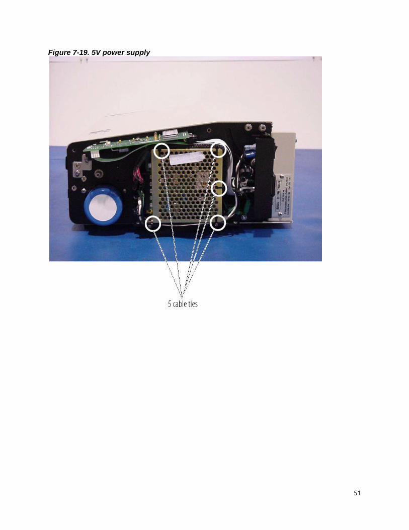
Figure 7-19. 5V power supply ........................................................................................................ 51
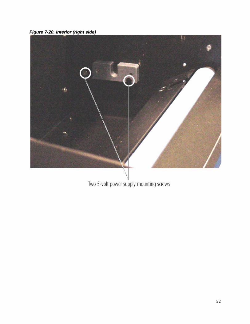
Figure 7-20. Interior (right side) ...................................................................................................... 52
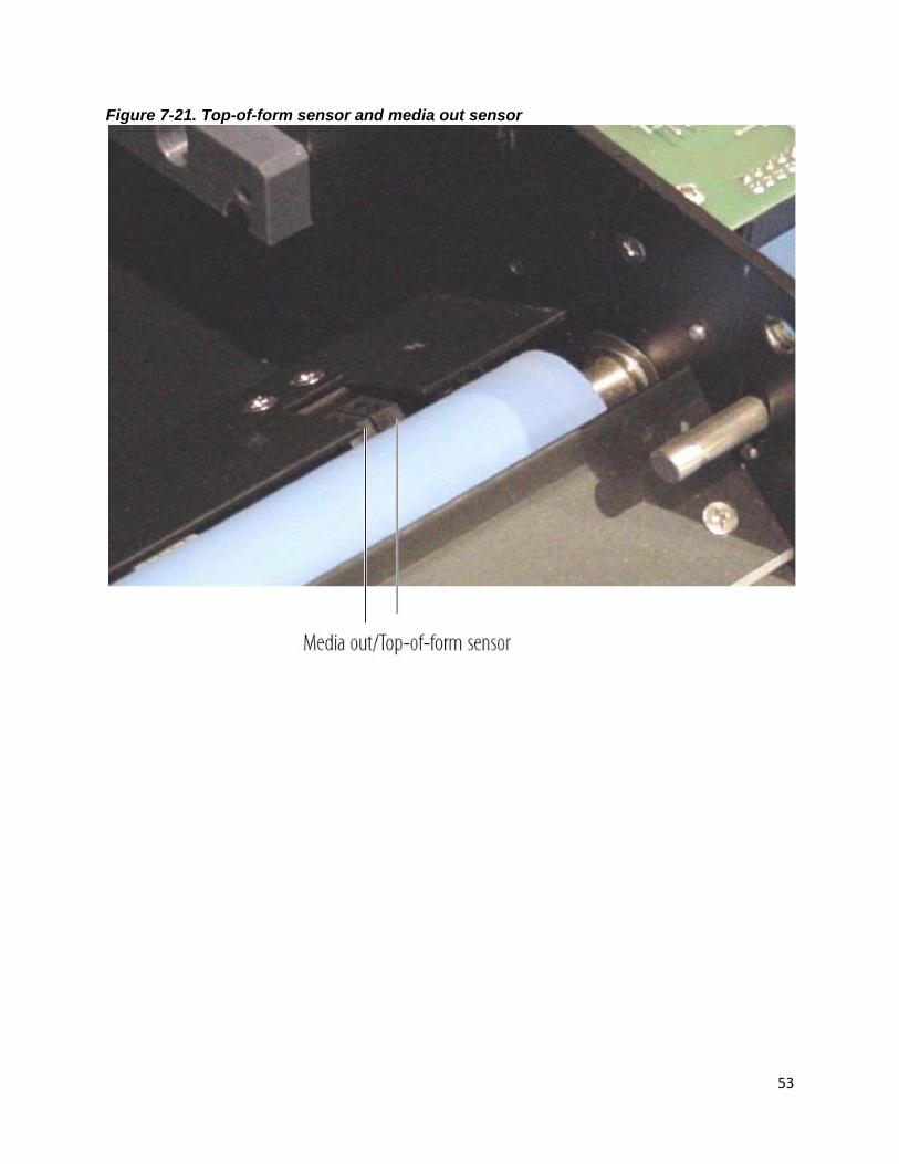
Figure 7-21. Top-of-form sensor and media out sensor ............................................................. 53
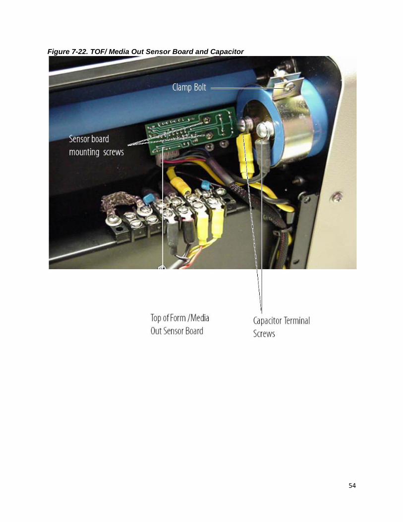
Figure 7-22. TOF/ Media Out Sensor Board and Capacitor ...................................................... 54
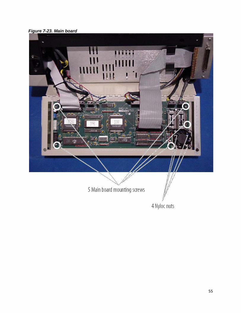
Figure 7-23. Main board .................................................................................................................. 55
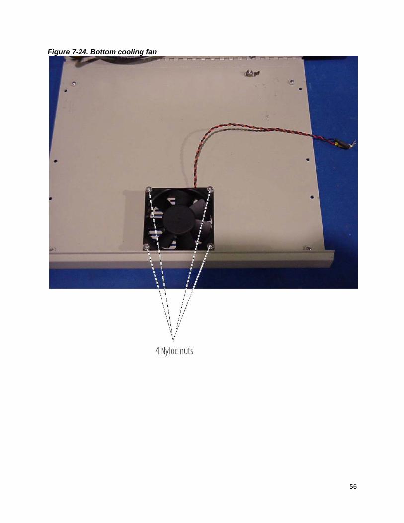
Figure 7-24. Bottom cooling fan ..................................................................................................... 56
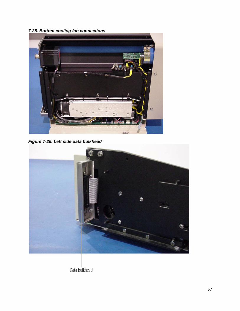
7-25. Bottom cooling fan connections ........................................................................................... 57
Figure 7-26. Left side data bulkhead ............................................................................................. 57
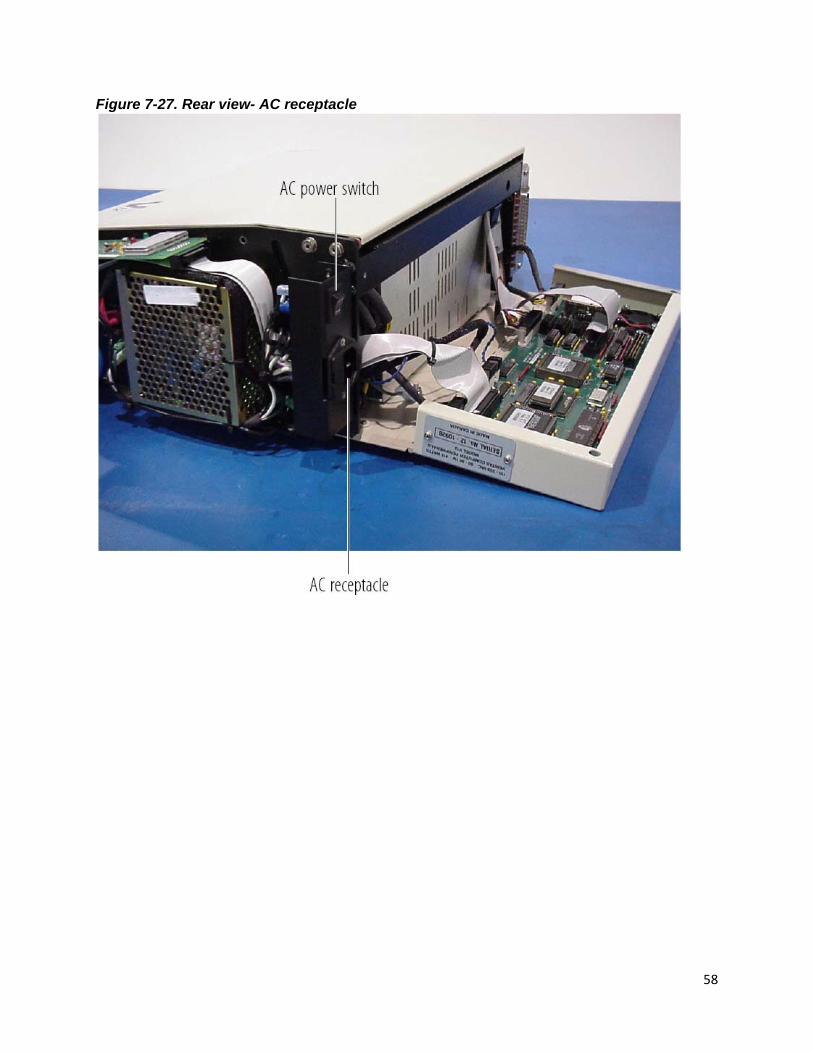
Figure 7-27. Rear view- AC receptacle ......................................................................................... 58
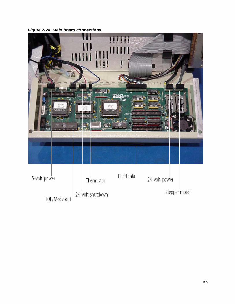
Figure 7-28. Main board connections ............................................................................................ 59
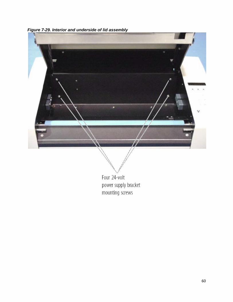
Figure 7-29. Interior and underside of lid assembly .................................................................... 60
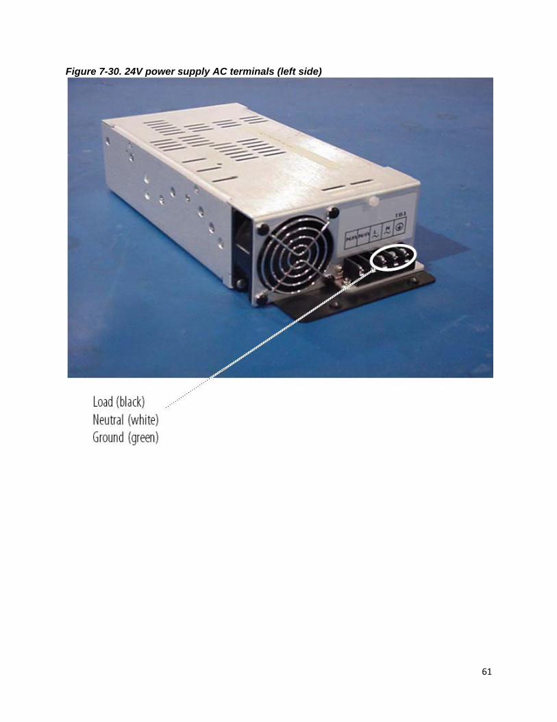
Figure 7-30. 24V power supply AC terminals (left side) ............................................................. 61
Figure 7-31. 24V power supply output studs (right side) ........................................................... 62
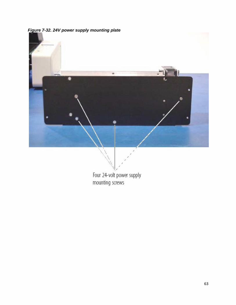
Figure 7-32. 24V power supply mounting plate ........................................................................... 63
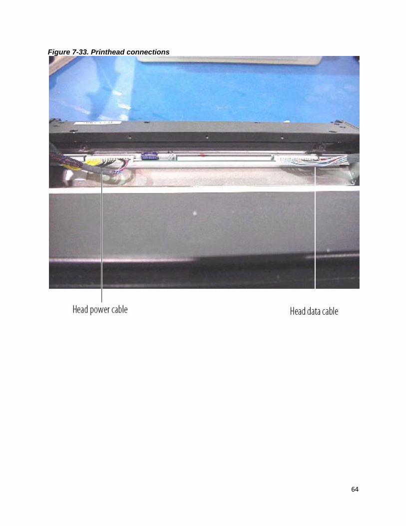
Figure 7-33. Printhead connections .............................................................................................. 64
Figure 7-34. Sample test plot ......................................................................................................... 65
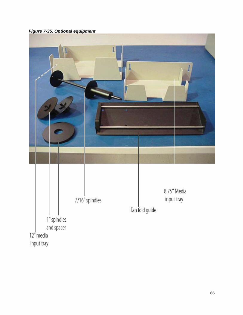
Figure 7-35. Optional equipment ................................................................................................... 66
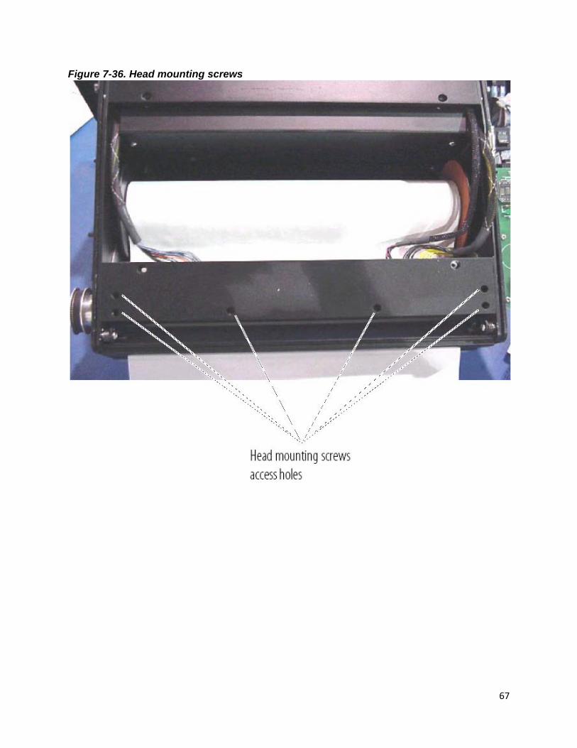
Figure 7-36. Head mounting screws ............................................................................................. 67
Figure 7-37. Head adjustment screws .......................................................................................... 68
TROUBLESHOOTING ............................................................................................................................ 69
8.1 INTRODUCTION ........................................................................................................................... 69
8.2 PROBLEMS ................................................................................................................................... 71
Error message displayed: NO MEDIA ....................................................................................... 71
Error message displayed: *_HOT!_* ......................................................................................... 71
Plotter does not plot ...................................................................................................................... 71
Plot is blotchy or faded ................................................................................................................ 73
Plot contrast is weak ..................................................................................................................... 73
Plot has black vertical lines ........................................................................................................ 74
Plot is wrong length ...................................................................................................................... 74
Paper is wrinkling or tearing along one edge......................................................................... 75

7
Plotter has no power ..................................................................................................................... 75
Plotter display is functioning but motor does not function................................................ 75
Changes cannot be made to control panel settings ............................................................. 75
Plot output speed is erratic ......................................................................................................... 75
Form feed does not stop at top-of-form marks ...................................................................... 75
Form feed stops before desired length .................................................................................... 76
Burning smell during plot, or “blooming” present on output ............................................ 76
Plot is skewed or unreadable...................................................................................................... 77
RACK MOUNT ADDENDUM ............................................................................................................. 77
9.1 SPECIFICATIONS ........................................................................................................................ 78
PHYSICAL ............................................................................................................................................ 78
Dimensions ...................................................................................................................................... 78
9.2 INSTALLATION ............................................................................................................................. 78
Installing the rails ........................................................................................................................... 78
Installing the plotter on the rack ................................................................................................ 80
Changing the interface line setting ........................................................................................... 80
Media installation ........................................................................................................................... 80
9.3 MAINTENANCE AND REPAIR .................................................................................................. 80
Removing the plotter from the rack .......................................................................................... 80
Removing the side panels ........................................................................................................... 81
Opening the back panel ............................................................................................................... 81
Accessing the bottom of the plotter ......................................................................................... 81
Cleaning the air filter ..................................................................................................................... 81
Replacing the display board ....................................................................................................... 82
Replacing the AC receptacle ....................................................................................................... 82
Other repair procedures ............................................................................................................... 82
10.0 DRIVER INSTALLATION .......................................................................................................... 83
CENTRONICS INTERFACE .............................................................................................................. 92
HARDWARE ......................................................................................................................................... 92
ASCII TABLES ..................................................................................................................................... 94
TOP-OF-FORM MARKS ..................................................................................................................... 95
INTERFACE CONNECTOR PIN ASSIGNMENT ........................................................................... 96

8
INTRODUCTION GENERAL DESCRIPTION The Imaging Systems Group V12 Thermal Plotter is a high-speed plotter suitable for office or field use. Its small size and lightweight, yet rugged construction allows it to be portable. The V12 uses thermal plotting technology, so it requires no chemicals or powdered ink. It is efficiently designed with only two moving parts; the platen roller and the motor. Interface parameter settings and other menu functions can be accessed from either the front panel or the remote host. It is capable of printing at four speeds: 1.0, 2.0, 3.0 and 4.0 inches per second. The V12 plots in both raster and character modes, and contains a 96 ASCII character set. It interfaces easily with Versatec and optionally Centronics or SCSI data sources. 1.1 MEDIA DESCRIPTION The V12 uses roll or fan-fold thermal paper, and certain thermal film media. Media width can be 12 inches, 11.654 inches, or 8.75 inches. The V12 accommodates regular thermal paper, papers with a protective top coating, and thinner field-grade thermal papers, as well as certain types of film media. Call your Imaging Systems Group customer service representative for media recommendations. A fan-fold paper guide is supplied with the plotter (Figure 3-1). Optional feeder trays are available from The Imaging Systems Group which stabilizes the paper for smooth intake (figure 7-35). This option is useful in field situations, or wherever vibration is a problem. These trays attach to the back of the plotter and are available in two media width. 1.3 ABOUT THIS MANUAL Please read this manual before using the plotter, in particular the Installation and Operation chapters, and the “Regular Maintenance” section in the Maintenance and Repair chapter. Please read the Troubleshooting chapter before attempting repairs. Pay special attention to warnings, cautions and notes. The following conventions are used in this manual: WARNING: Indicates possible bodily injury if procedure is not followed exactly. CAUTION: Indicates possible equipment damage unless procedure is followed correctly. NOTE: Indicates a general rule for a procedure, or an exception to a rule.
This symbol indicates an area of possible concern due to static discharge into the circuitry. When you see this symbol in the manual, please observe proper static precautions to minimize damage to the circuitry

9
SPECIFICATIONS 2.1 FUNCTIONAL Operation Command panel Top mounted on the desktop version. Front mounted on the rackmount version. Full function alphanumeric display. Four push buttons. LED display.
Command modes Plotting mode. Printing mode.
Features Microprocessor controlled. Two custom user settings. User settings stored while power off. Automatic head temperature feedback.
Panel settings On-line, off-line. User 1 and User 2 custom settings. Manual plot speed select: 1.0, 2.0, 3.0 and 4.0 inches per second (ips). Manual plot width selection: 216, 216 right justified, 264, 264 right
justified and 296 bytes per scan (bps). Test plot, test print. 203 dots per inch (dpi) vertical resolution - standard. 200 dots per inch (dpi) vertical emulation. Vertical scaling: From no scale to +30/64” in 1/64” increments.
Media selection: Light paper, heavy paper, light film, heavy film. 10 Contrast settings: C1,
C2, C3, C4, C5, C6, C7, C8, C9, C10. Manual form advance. Form feed. Form feed length adjust: 1.0, 2.0, 3.0, 4.0, 6.0, 8.0, 10.0, 12.0, 14.0, 16.0 inches, top of form (TOF) sensing, programmable past top of form (PTOF). TOF voltage detection. Beeper select: On, off, pulsed audible alert. 24 volt error warning. Thermistor error warning.
Plot speeds 1. 1.0 inch per second. 2. 2.0 inches per second. 3. 3.0 inches per second. 4. 4.0 inches per second. 5. Film mode: 1.0 inch per second.
Condition detection Media out. Top of form. Head temperature. Idle state power supply shutdown. Top of form voltage.
10
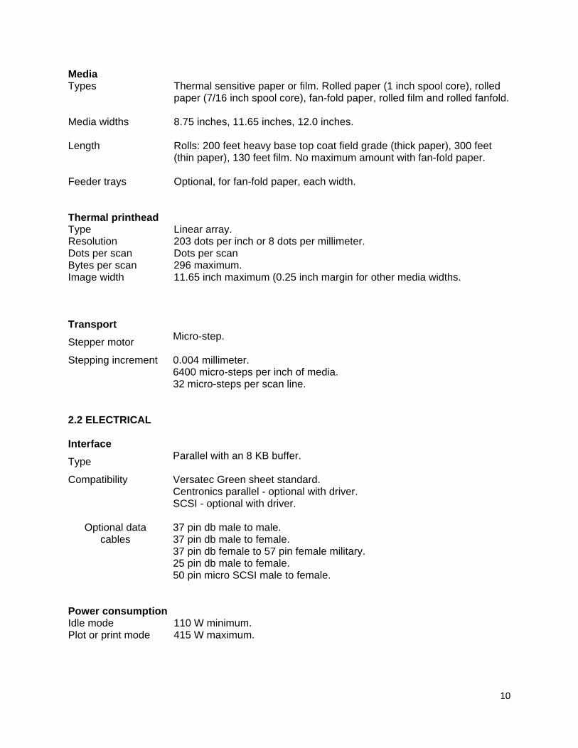
Media Types Thermal sensitive paper or film. Rolled paper (1 inch spool core), rolled
paper (7/16 inch spool core), fan-fold paper, rolled film and rolled fanfold.
Media widths 8.75 inches, 11.65 inches, 12.0 inches.
Length Rolls: 200 feet heavy base top coat field grade (thick paper), 300 feet (thin paper), 130 feet film. No maximum amount with fan-fold paper.
Feeder trays Optional, for fan-fold paper, each width. Thermal printhead Type Linear array. Resolution 203 dots per inch or 8 dots per millimeter. Dots per scan Dots per scan Bytes per scan 296 maximum. Image width 11.65 inch maximum (0.25 inch margin for other media widths.
Transport Stepper motor Micro-step.
Stepping increment 0.004 millimeter. 6400 micro-steps per inch of media. 32 micro-steps per scan line. 2.2 ELECTRICAL Interface Type Parallel with an 8 KB buffer.
Compatibility Versatec Green sheet standard. Centronics parallel - optional with driver. SCSI - optional with driver.
Optional data
cables 37 pin db male to male. 37 pin db male to female. 37 pin db female to 57 pin female military. 25 pin db male to female. 50 pin micro SCSI male to female.
Power consumption Idle mode 110 W minimum. Plot or print mode 415 W maximum.

11
Power requirements Voltage Auto selectable input. 110 Volts AC @ 60 Hertz or 220 Volts AC @ 50 Hertz.
Current 6 Amps maximum @ 110 Volts. 2 Amps nominal @ 110 Volts.
3 Fuse 250 Volts / 6.3 Amps.
2.3 PHYSICAL Dimensions Desktop Rackmount
Height 6.25 inches 5.75 inches
Width 17.0 inches 19.0 inches
Weight Desktop Rackmount
Net 28 pounds 40 pounds
2.4 ENVIRONMENTAL Temperature Operating range 32º to 122º Fahrenheit / 0º to 50º Celsius. Storage range 14º to 158ºFahrenheit / -10º to 70º Celsius. Other Operating humidity 5% to 95% non-condensing. Certification FCC Class “A” verified for electromagnetic interference. European CE.
12
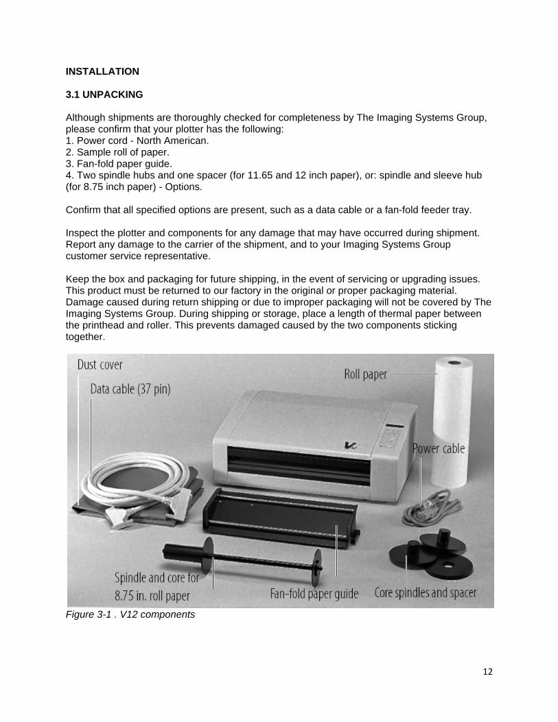
INSTALLATION 3.1 UNPACKING Although shipments are thoroughly checked for completeness by The Imaging Systems Group, please confirm that your plotter has the following: 1. Power cord - North American. 2. Sample roll of paper. 3. Fan-fold paper guide. 4. Two spindle hubs and one spacer (for 11.65 and 12 inch paper), or: spindle and sleeve hub (for 8.75 inch paper) - Options. Confirm that all specified options are present, such as a data cable or a fan-fold feeder tray. Inspect the plotter and components for any damage that may have occurred during shipment. Report any damage to the carrier of the shipment, and to your Imaging Systems Group customer service representative. Keep the box and packaging for future shipping, in the event of servicing or upgrading issues. This product must be returned to our factory in the original or proper packaging material. Damage caused during return shipping or due to improper packaging will not be covered by The Imaging Systems Group. During shipping or storage, place a length of thermal paper between the printhead and roller. This prevents damaged caused by the two components sticking together.
Figure 3-1 . V12 components
13
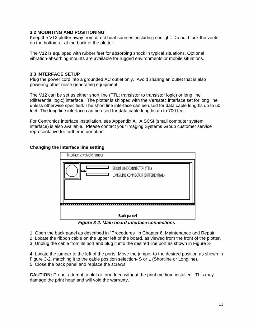
3.2 MOUNTING AND POSITIONING Keep the V12 plotter away from direct heat sources, including sunlight. Do not block the vents on the bottom or at the back of the plotter. The V12 is equipped with rubber feet for absorbing shock in typical situations. Optional vibration-absorbing mounts are available for rugged environments or mobile situations. 3.3 INTERFACE SETUP Plug the power cord into a grounded AC outlet only. Avoid sharing an outlet that is also powering other noise generating equipment. The V12 can be set as either short line (TTL; transistor to transistor logic) or long line (differential logic) interface. The plotter is shipped with the Versatec interface set for long line unless otherwise specified. The short line interface can be used for data cable lengths up to 50 feet. The long line interface can be used for data cable lengths up to 700 feet. For Centronics interface installation, see Appendix A. A SCSI (small computer system interface) is also available. Please contact your Imaging Systems Group customer service representative for further information. Changing the interface line setting
Figure 3-2. Main board interface connections
1. Open the back panel as described in “Procedures” in Chapter 6, Maintenance and Repair. 2. Locate the ribbon cable on the upper left of the board, as viewed from the front of the plotter. 3. Unplug the cable from its port and plug it into the desired line port as shown in Figure 3- 4. Locate the jumper to the left of the ports. Move the jumper to the desired position as shown in Figure 3-2, matching it to the cable position selection- S or L (Shortline or Longline). 5. Close the back panel and replace the screws. CAUTION: Do not attempt to plot or form feed without the print medium installed. This may damage the print head and will void the warranty.
14
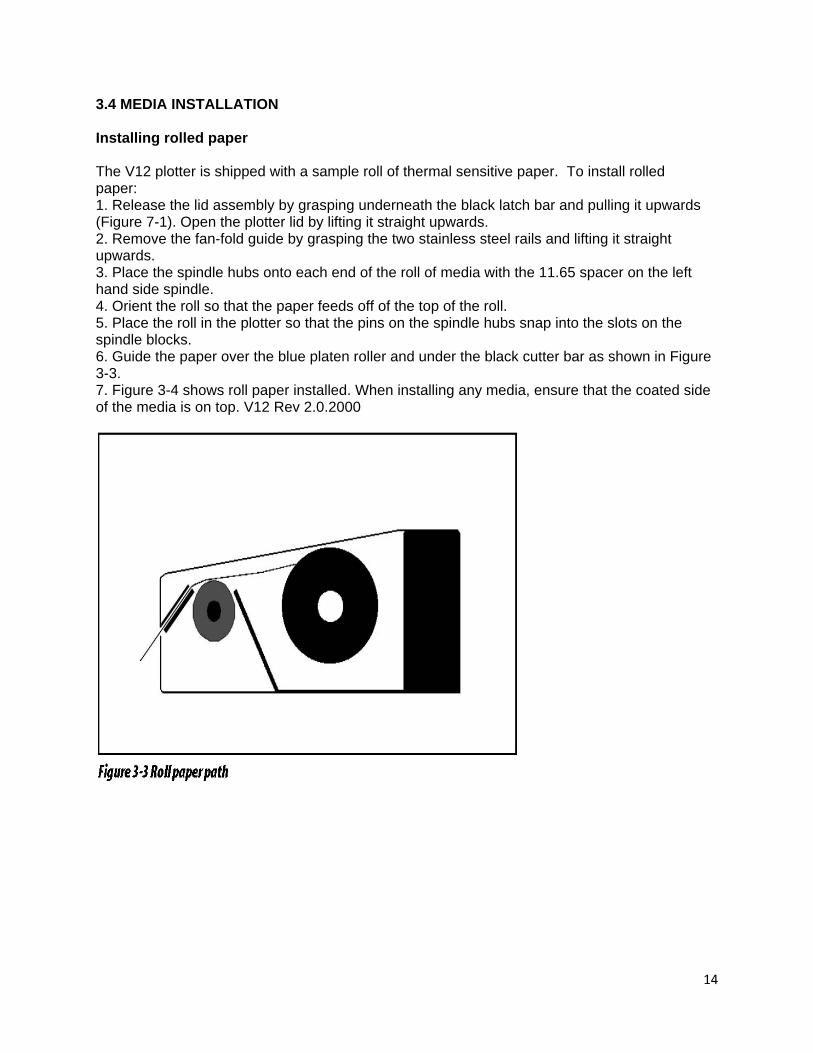
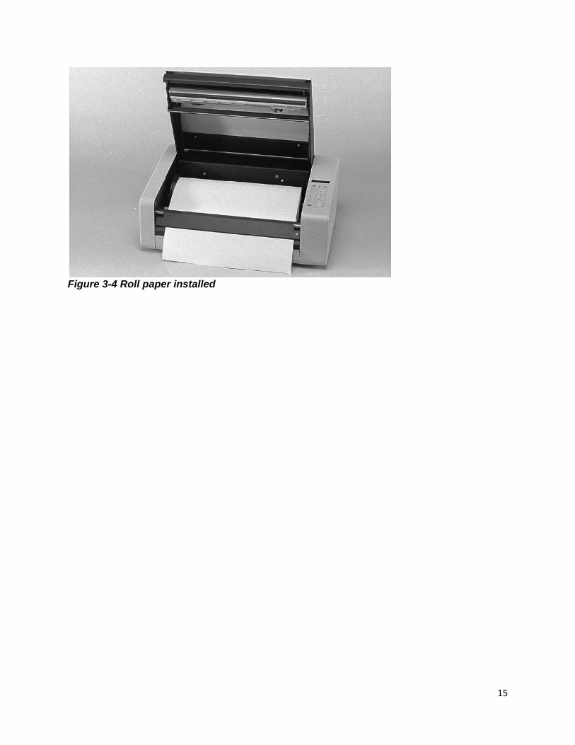
3.4 MEDIA INSTALLATION Installing rolled paper The V12 plotter is shipped with a sample roll of thermal sensitive paper. To install rolled paper: 1. Release the lid assembly by grasping underneath the black latch bar and pulling it upwards (Figure 7-1). Open the plotter lid by lifting it straight upwards. 2. Remove the fan-fold guide by grasping the two stainless steel rails and lifting it straight upwards. 3. Place the spindle hubs onto each end of the roll of media with the 11.65 spacer on the left hand side spindle. 4. Orient the roll so that the paper feeds off of the top of the roll. 5. Place the roll in the plotter so that the pins on the spindle hubs snap into the slots on the spindle blocks. 6. Guide the paper over the blue platen roller and under the black cutter bar as shown in Figure 3-3. 7. Figure 3-4 shows roll paper installed. When installing any media, ensure that the coated side of the media is on top. V12 Rev 2.0.2000
15
Figure 3-4 Roll paper installed

16
Installing fan-fold paper 1. Release the lid assembly by grasping underneath the black latch bar and pulling it upwards- figure 7-1. Open the plotter lid by lifting it straight upwards. 2. Place the fan-fold guide on the spindle blocks, orienting it so that it slopes towards the front of the plotter. See Figure 3-5. 3. Slide the width bracket on the fan-fold guide to fit the paper you are using. See Figure 3-6
Figure 3-6. Fan-fold feeder tray
4. Feed the fan-fold paper through the slot in the back of the plotter located between the lid and the top of the rear panel. 5. Guide the paper under the rear fan-fold bar and over the top of the front fan-fold bar. 6. Guide the paper over the blue platten roller and under the black cutter bar as shown in Figures 3-7 and 3-8. CAUTION: Before plotting or testing on any print medium, make sure that the media setting is correct. Incorrect settings may result in damage to the printhead and will void the warranty. The media may also be damaged. See Chapter 4, “Operation” for menu setting instructions.
Figure 3-7. Fan-fold paper path
17
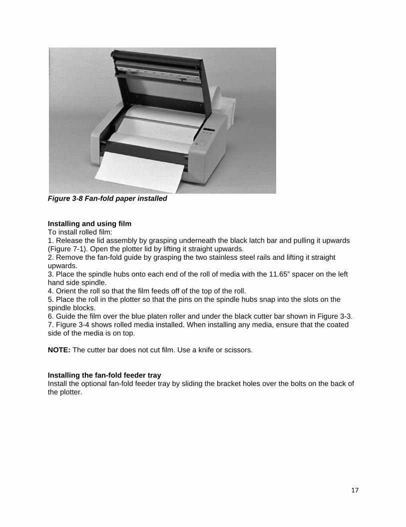
Figure 3-8 Fan-fold paper installed Installing and using film To install rolled film: 1. Release the lid assembly by grasping underneath the black latch bar and pulling it upwards (Figure 7-1). Open the plotter lid by lifting it straight upwards. 2. Remove the fan-fold guide by grasping the two stainless steel rails and lifting it straight upwards. 3. Place the spindle hubs onto each end of the roll of media with the 11.65” spacer on the left hand side spindle. 4. Orient the roll so that the film feeds off of the top of the roll. 5. Place the roll in the plotter so that the pins on the spindle hubs snap into the slots on the spindle blocks. 6. Guide the film over the blue platen roller and under the black cutter bar shown in Figure 3-3. 7. Figure 3-4 shows rolled media installed. When installing any media, ensure that the coated side of the media is on top. NOTE: The cutter bar does not cut film. Use a knife or scissors. Installing the fan-fold feeder tray Install the optional fan-fold feeder tray by sliding the bracket holes over the bolts on the back of the plotter.

18
OPERATION 4.1 POWER SUPPLY PRECAUTIONS Turn the plotter power switch OFF before doing any of the following: 1. Unplugging the plotter. 2. Cleaning the printhead. 3. Opening the plotter for maintenance or service. 4. Placing hands or tools near any internal parts. WARNING: There are voltage hazards inherent in the printhead power supply and AC input wiring. Take reasonable precautions to avoid electrical shock.
CAUTION: Take care not to discharge static into the plotter. This may cause damage to the integrated circuits or to other electronic components. Use an approved method of static dissipation such as touching a grounded source, to prevent component damage.
4.2 USING THE CONTROL PANEL To turn the plotter on, press the main power switch located at the back right side of the desktop plotter version, or at the front left side with the rackmount version. The display will show IDLE M1 and the ONLINE light will be illuminated. When the ONLINE light is on, the plotter is ready to receive data from the host. Changes to the control panel settings must be made in OFFLINE mode. The control panel is shown in Figure 4-1. It consists of an LED display, three condition lights, and four push buttons.
Figure 4-1. Control panel
19
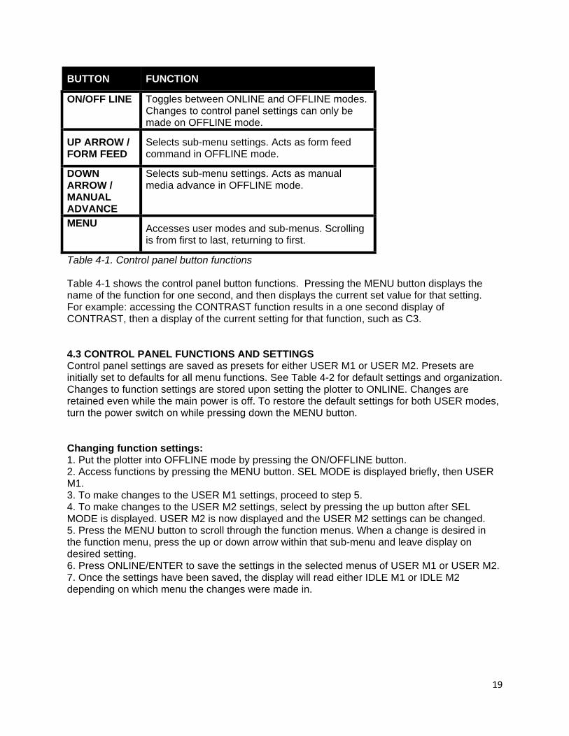
BUTTON FUNCTION
ON/OFF LINE Toggles between ONLINE and OFFLINE modes. Changes to control panel settings can only be made on OFFLINE mode.
UP ARROW / FORM FEED
Selects sub-menu settings. Acts as form feed command in OFFLINE mode.
DOWN ARROW / MANUAL ADVANCE
Selects sub-menu settings. Acts as manual media advance in OFFLINE mode.
MENU Accesses user modes and sub-menus. Scrolling is from first to last, returning to first.
Table 4-1. Control panel button functions Table 4-1 shows the control panel button functions. Pressing the MENU button displays the name of the function for one second, and then displays the current set value for that setting. For example: accessing the CONTRAST function results in a one second display of CONTRAST, then a display of the current setting for that function, such as C3. 4.3 CONTROL PANEL FUNCTIONS AND SETTINGS Control panel settings are saved as presets for either USER M1 or USER M2. Presets are initially set to defaults for all menu functions. See Table 4-2 for default settings and organization. Changes to function settings are stored upon setting the plotter to ONLINE. Changes are retained even while the main power is off. To restore the default settings for both USER modes, turn the power switch on while pressing down the MENU button. Changing function settings: 1. Put the plotter into OFFLINE mode by pressing the ON/OFFLINE button. 2. Access functions by pressing the MENU button. SEL MODE is displayed briefly, then USER M1. 3. To make changes to the USER M1 settings, proceed to step 5. 4. To make changes to the USER M2 settings, select by pressing the up button after SEL MODE is displayed. USER M2 is now displayed and the USER M2 settings can be changed. 5. Press the MENU button to scroll through the function menus. When a change is desired in the function menu, press the up or down arrow within that sub-menu and leave display on desired setting. 6. Press ONLINE/ENTER to save the settings in the selected menus of USER M1 or USER M2. 7. Once the settings have been saved, the display will read either IDLE M1 or IDLE M2 depending on which menu the changes were made in.
20
Test mode The TESTMODE function allows the user make a test plot (see Figure 7-34). Approximately four inches of plot are produced, in a pattern consisting of a 50% grey scale, small and large checkerboard pattern, and two 1/2” bands of all-black. It will also display the plotters’ firmware revision and strobe count. This enables the user to see that the plotter is creating an image, feeding the paper correctly, and that contrast levels and media settings are acceptable, as well as testing the print function. To change from the default TESTMODE setting of INACTIVE, press the up button in the TEST MODE sub-menu to display PLOT TST. Then press the ONLINE button to execute the test. Contrast The CONTRAST function adjusts the density of the output plots, the default setting is C1. C1 and increment settings (C1 through C10) are relative values. Determination of plot quality and the need to increase or decrease contrast is determined after a test plot is output. If the output is extremely dark, very faint, or irregular, first check that the media setting is correct- see “Media” section of this chapter. If the contrast needs to be adjusted, change the contrast setting by pressing the up button while in the CONTRAST sub-menu. Starting at the lowest value, adjust the contrast level one value at a time, testing each adjustment. This is particularly important when using lightweight papers or a media with unknown specifications. CAUTION: Thermal plotting technology involves high temperatures. Incorrect media or contrast settings can damage the printhead or other components and void the warranty. Media damage can also occur. Speed The SPEED function adjusts the speed of the plot output. The default setting is 1.0 inch per second. Change the speed setting by pressing the up or down buttons in the SPEED sub-menu. The 1.0 inch per second setting results in the highest quality output. The next speeds are 2.0, 3.0, and 4.0 inches per second, respectively. If the plot speed is erratic, or if output quality is unacceptable, such problems may arise when data enters the plotter at a slower rate than the set plot speed. This is most likely to occur on the 4.0 inches per second setting. Lowering the plot speed enables the plotter to match the rate of data from the host and produces a smoother output plot. When the media setting is FILM, the plotter fixes the speed for maximum quality, plotting at 1.0 inch per second. See “Thermal printhead” in Chapter 5, Theory of Operation, for more details.

21
Media The MEDIA function adjusts the printhead for various papers or film. The default setting is LT PAPER (light paper). Note that if you are using other media, you must adjust the media setting. Incorrect settings can damage the printhead. If unsure of the media specifications, start at the LT PAPER setting and then increase the setting to HV PAPER if necessary. Change the media setting by pressing the up or down arrows in the MEDIA sub-menu. Select LT PAPER (light paper), HV PAPER (heavy paper), LT FILM (light film) or HV FILM (heavy film). Note that in FILM mode the print head’s normal strobe time is raised to compensate for the thicker media, which requires a slower plot speed- see “Speed” section of this chapter. Do not use film settings on any other media. CAUTION: Thermal plotting technology involves high temperatures. Incorrect media or contrast settings can damage the printhead or other components and void the warranty. Media damage can also occur. Scaling The SCALING function stretches or scales the plot over a 36-inch length. The default setting is NO SCALE. To determine if scaling is needed, plot a job of a known length and measure it. Adjustments can be made to the scaling in increments of 1/64-inch. Change the scaling setting by pressing the up or down buttons in the SCALING sub-menu. The up button accesses positive (stretch) increments from +1/64-inch to +30/64-inch. Beeper The BEEPER function changes the error sound properties. The plotter beeps when an error condition is determined. Error conditions result when the plotter is out of paper or when the printhead is too hot to operate. These conditions display on the control panel as NO MEDIA or *_HOT_!*. The error status light below the display flashes. The default audio setting is PULSED. On this setting, the plotter will emit four long beeps upon error detection. If the plotter is in a noisy environment or if immediate action must be taken regarding error detection, change the audio setting to ON. Change the beeper setting using the up or down buttons in the Beeper sub-menu. On this setting, the plotter will emit a continuous beep tone until the error is corrected. This setting does not apply to the *HOT* error, since stopping the tone would require turning the power off (see “Automatic head temperature feedback” in Chapter 5, Theory of Operation). If you do not require an audible error signal, turn the audio off. Change the setting by pressing the up or down buttons in the BEEPER sub-menu.

22
Form feed length The FFLENGTH function adjusts the distance that the media is advanced upon pressing the FORM FEED button in OFFLINE mode. The default setting is 2 inches. The length can be adjusted for trailer length (the length of media advance after the plot has finished), or for various fan-fold paper lengths. The plotter senses fan-fold top-of-form marks. These marks signal the plotter to stop the form feed at a consistent distance from the perforated edge of the paper. The top-of-form sensor is located in the paper loading area, which is to the rear of the platen roller and on the right side of the plotter- see Figure 7-17. Plotting begins immediately after the perforation, unless margins are defined in the host software. If you are using paper with Top of Form (TOF) marks, ensure that the form feed length is set to “TOF sens” or a distance equal to, or greater than the distance between these marks. The form feed will stop when it reaches the FORMFEED setting value, or when it senses a top-of-form mark, whichever comes first. Change the form feed length settings by pressing the up or down buttons in the FFLENGTH sub-menu. Settings are 1.0, 2.0, 3.0, 4.0, 6.0, 8.0, 10.0, 12.0, 14.0 and 16.0 inches, TOF sens, PTOF ena- see page 4-9 for TOF display descriptions. Scan width The SCANWDTH function adjusts the scan width of the plot, defined in bytes per line. The default scan width is 216 (right justified) bytes per line. Unless you are using RLTER (remote line terminate) commands, the plotter scan width must be set to the same byte count as the rastered data from the host. Setting the scan width higher than the byte count of the raster data does not create a wider plot. Setting the scan width incorrectly results in skewed output as the data “wraps” and finishes the scan on the next line. This condition is identifiable on the plot in Figure 8-8. Change the scan width settings by pressing the up or down arrows in the SCANWDTH sub-menu. The small arrow in the display, to the right of the numerals, indicates no margin. If the arrow is not present, the plotter inserts a left margin of 16 bytes (5/8-inch). SCANWDTH settings can be 216 bytes, 216 bytes no margin, 264 bytes, 264 bytes no margin, or 296 bytes. Since 296 bytes is the maximum width of the plot media, no margin is placed. For more details on SCANWDTH and using remote line terminate (RLTER) commands, see “Interface timing and signals” in Chapter 5, Theory of Operation.

23
Vertical resolution The VERT RES function adjusts the vertical resolution of the plot along the media length. The default setting is 203 scans per inch (spi) which is equal to 203 dots per inch (dpi). Note that the horizontal resolution is determined by the printhead dot density, which is 203 dpi. Change the vertical resolution setting using the up or down buttons in the VERT RES sub-menu. The V12 plotter can emulate the 200 dpi vertical resolution setting, to match the rastered host data (for Imperial units). The emulation is approximate, within ±0.04%. TOF display descriptions TOF sens enables the top-of-form sensor to use fan-fold paper with “I” marks up to 18” apart. PTOF ena. programmable advance past top-of-form enable, allows custom length media to be used. Advance past TOF mark detection allows flexibility in lining up a variety of fan-fold media with TOF marks in non standard positions.
24
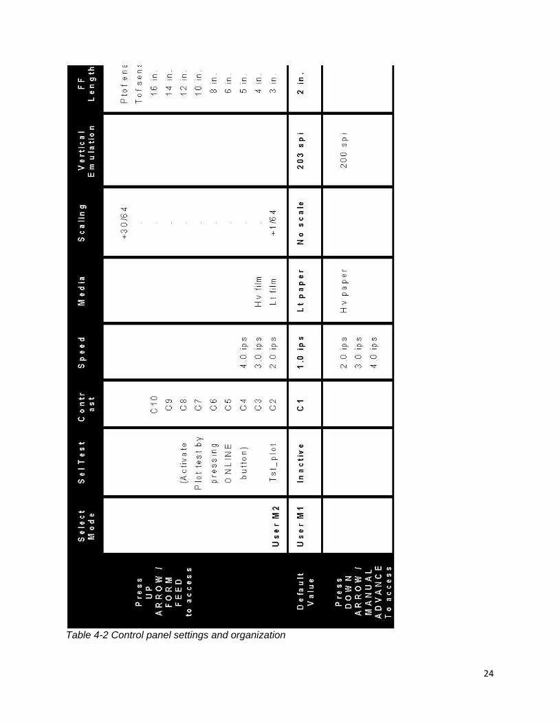
Table 4-2 Control panel settings and organization
25
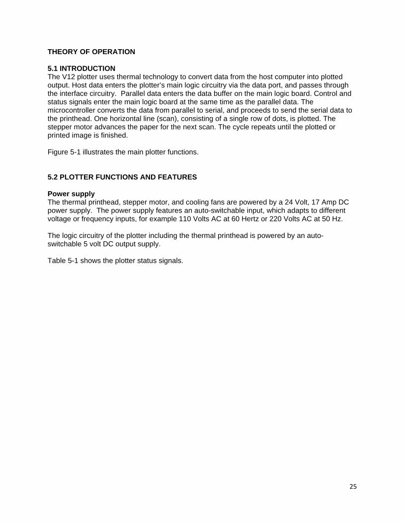
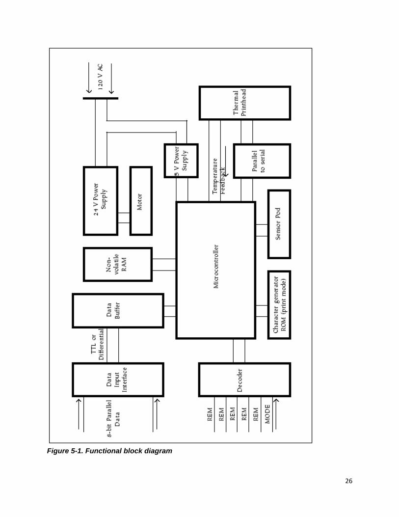
THEORY OF OPERATION 5.1 INTRODUCTION The V12 plotter uses thermal technology to convert data from the host computer into plotted output. Host data enters the plotter’s main logic circuitry via the data port, and passes through the interface circuitry. Parallel data enters the data buffer on the main logic board. Control and status signals enter the main logic board at the same time as the parallel data. The microcontroller converts the data from parallel to serial, and proceeds to send the serial data to the printhead. One horizontal line (scan), consisting of a single row of dots, is plotted. The stepper motor advances the paper for the next scan. The cycle repeats until the plotted or printed image is finished. Figure 5-1 illustrates the main plotter functions. 5.2 PLOTTER FUNCTIONS AND FEATURES Power supply The thermal printhead, stepper motor, and cooling fans are powered by a 24 Volt, 17 Amp DC power supply. The power supply features an auto-switchable input, which adapts to different voltage or frequency inputs, for example 110 Volts AC at 60 Hertz or 220 Volts AC at 50 Hz. The logic circuitry of the plotter including the thermal printhead is powered by an auto-switchable 5 volt DC output supply.
Table 5-1 shows the plotter status signals.
26
Figure 5-1. Functional block diagram
27
MAINTENANCE AND REPAIR NOTE: Do not attempt to repair or modify any component of the V12 while it is under warranty. If a component fails, it may be replaced free of charge in accordance with the warranty procedures in this manual. Attempting unauthorized repairs or modifications will void the warranty. WARNING: There are voltage hazards inherent in the printhead power supply and AC input wiring. Take reasonable precautions to avoid electrical shock. Never service any electrical component of the V12 while the power cord is connected. Severe electrical shock may result. CAUTION: Take care not to discharge static into the plotter. This may cause damage to integrated circuits or other electronic components. Dissipate static by touching a grounded source, or wearing a static dissipating wrist strap, before using tools on the plotter or touching internal components.
This symbol indicates an area of possible concern due to static discharge into the circuitry. When you see this symbol in the manual, please observe proper static precautions to minimize damage to the circuitry.
6.1 MAINTENANCE GUIDELINES In order to minimize the complexity of troubleshooting and repairs, the V12 plotter is composed, wherever possible, of field-replaceable units (FRUs). The Imaging Systems Group does not recommend troubleshooting at a component level, but rather to the level of these FRUs. This chapter and the troubleshooting chapter of this manual follow this approach, resulting in faster and easier repairs. Replacing or repairing FRUs, rather than smaller components, minimizes downtime and simplifies procedures. This chapter provides detailed information on servicing and maintaining the V12. Follow the guidelines below to make problem identification and servicing easier. Use caution while troubleshooting the V12. Turn the power off and unplug the power cord to prevent electric shock. Replace one thing at a time when troubleshooting, will make it easier to determine what is causing trouble. If changes are made to more than one component at a time and a solution or new problem arises, it is more difficult to attribute the change to a single part. Test each change thoroughly after each phase of repair before moving on. This method ensures each part of the repair is correct.
28
6.2 REGULAR MAINTENANCE The V12 thermal plotter is designed to require minimal preventative maintenance. If the thermal printhead and platen roller are cleaned regularly, and the plotter is kept free of debris, extra maintenance and repairs will be kept to a minimum. This preventative maintenance is the owner/operators responsibility. Damage to the plotter that has in The Imaging Systems Group's opinion resulted from neglect or misuse, will not be covered under warranty. CAUTION: No parts of the V12 require lubrication. All bearings are sealed and self-lubricating. Bearings must be replaced in pairs if one fails. Cleaning the thermal printhead After prolonged use, the thermal printhead picks up fibers from the paper passing under it. These fine fibers collect and compact on portions of the printhead, blocking the contact it makes with the paper during a plot and causing faded patches. Poor contact between the printhead and paper may also cause the affected heating elements (nibs) to fail prematurely because of improper heat dissipation to the paper. Clean the printhead every time a new roll of paper or film is installed. 1. Turn the plotter power off. 2. Moisten (do not soak) a soft, lint-free cloth with 99% isopropyl alcohol. Rub gently along the length of the printhead. 3. Allow the alcohol to evaporate completely before using the plotter. CAUTION: Do not touch the printhead with your fingers or other object. The oil on your skin contaminates the printhead, which lessens plot quality and shortens the print head’s life span. Cleaning the platen roller After prolonged use, the platen roller picks up fibers from the paper passing above it. These fine fibers collect and compact on portions of the platen roller, creating bumps. The uneven surface of the roller may cause the printhead to contact the passing paper unevenly, producing a blotchy or faded plot. Clean the platen roller when it appears dirty, or after approximately three rolls of paper or film have been plotted. 1. Turn the plotter power off. 2. Moisten (do not soak) a soft, lint-free cloth with 99% isopropyl alcohol. Rub gently along the length of the roller turning the roller as necessary to remove paper fragments and dust. 3. Allow the alcohol to evaporate completely before using the plotter. In highly dusty or dirty environments, further cleaning by use of compressed air to keep the plotter clean is recommended. Always clean the head and platten roller with isopropyl alcohol after blowing dust out of the plotter.
29
Cleaning the Top of Form/Media out sensors After prolonged use, especially in field use, the plotters optical sensors will begin to become covered with fibers from the media passing above them, as well as dust in the air. This residue will reduce the effectiveness of the sensors. Clean the sensors when every three rolls of paper or film is installed, to retain the factory set sensitivity of the sensors. 1. Turn the plotter power off. 2. Moisten a Q-tip with 99% isopropyl alcohol. Wipe gently over the optical sensors making sure to get past the outer plastic protective case on the sensors when cleaning. 3. Allow the alcohol to evaporate completely before using the plotter. 6.3 REPAIR PROCEDURES Please refer to Chapter 8, Troubleshooting, before attempting any repair procedure. Tools A selection of tools is necessary to perform most of the maintenance and repairs on the V12. These tools include, but may not be limited to: Phillips screwdrivers: #1, #2 Flat screwdriver: #0 Allen keys: 5/32 inches Hex socket drivers: 5/16 inches 11/32 inches 3/8 inches Needle nose pliers Small wire cutters Digital multi-meter Potentiometer trimmer tool Opening the plotter lid 1. Release the lid assembly by grasping underneath the black latch bar and pulling it upwards- Figure 7-1. Open the plotter lid by lifting it straight upwards. Note the lid does not fully open to 90
0.
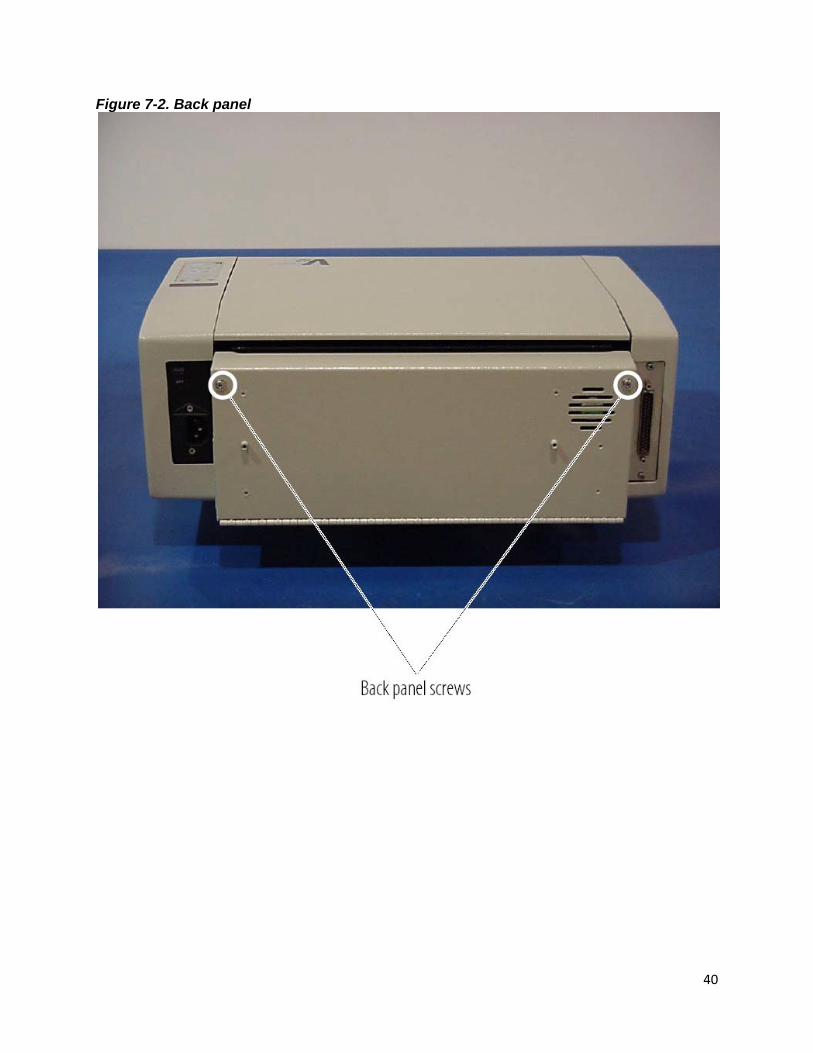
Removing the top cover Remove the four philips pan head screws located behind the head assembly and on the rear support plate. Opening the back panel 1. Remove the two 6/32” x 2” Phillips pan head screws and washers from the top left and top right of the back panel as shown in Figure 7-2. The back panel hinges down- Figure 7-3.
30
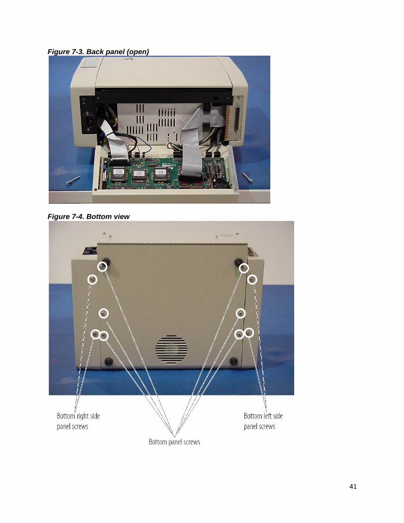
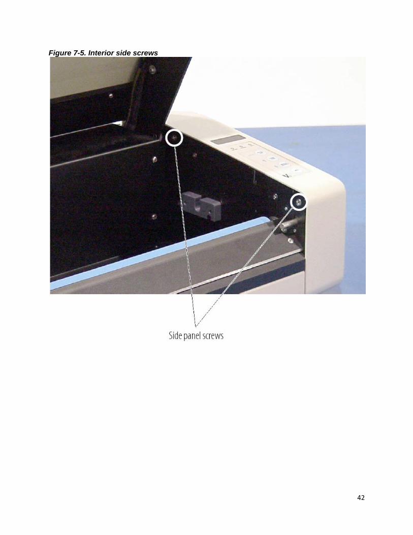
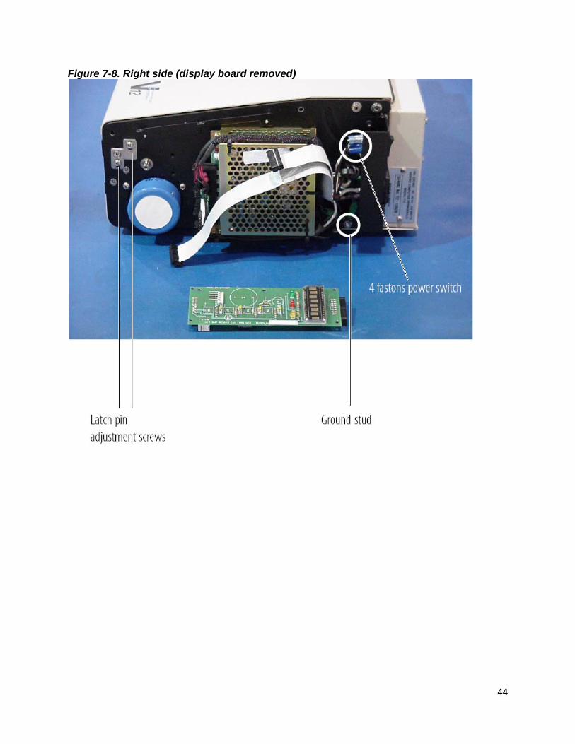
Removing the side panels 1. On the bottom of the plotter, remove the two side 6/32” x 3/8” screws and washers from the appropriate side- figure 7-4. 2. Open the plotter lid. Remove the two interior side panel 6/32” x 3/8” screws from the appropriate side as shown in Figure 7-5. 3. Remove the side panel. NOTE: For the right side panel, disconnect the 5-pin control panel cable as shown in Figure 7-6. Note the cable orientation for reinstallation. Opening the bottom panel 1. Remove the six bottom panel screws shown in Figure 7-4. 2. The bottom plate hinges down. Take care not to overstress the fan wires, or chassis grounding wire. Replacing the display board The display board is located underneath the control panel switch pad. Switches are sealed in the switch pad and should they fail, replacement of the switch pad will be necessary. 1. Remove the right side panel as described in this chapter. 2. Remove the two 4/40” x 1/4” display board screws as shown in Figure 7-7. 3. Disconnect the two cables from the front and rear of the display board. See Figure 7-8. 4. Replace the display board and reverse steps to reassemble. Replacing the thermal printhead 1. Open the plotter lid. Disconnect the data and power cables from the back of the printhead. (see Figure 7-1). 2. Remove the media pressure bar below the printhead. 3. Using a probe or small screwdriver, push the rear spring pin on the left side of the plotter lid until the head plate can be rotated downwards from the hole (see Figure 7-9). Push in the front of the pin; pull the left side of the head plate downwards until the plate is free of the left side arm. 4. Remove the printhead by pulling to the left thereby disengaging the right head plate pins from the right side arm. See Figure 7-10. 5. Remove the printhead from its plate by removing the six plate mounting screws shown in Figure 7-11. \ 6. Replace the printhead and reverse steps to reassemble. NOTE: When replacing the printhead and plate, ensure that the tension springs (shown in Figure 7-11) are securely seated in their holes in the lid.
31
Adjusting the printhead This adjustment should only be required after head replacement, and should not be done until after a sample plot has been created. 1. Remove the top cover as described in this chapter. 2. Loosen but do not remove the 6 screws located on the head plate. These screws can be accessed through the holes in the top spring backing plate (see Figure 7-11). 3. Use a 5/32” Allen key to adjust the head alignment to the platten roller, refer to Figure 7-37 Adjust only one side of the head at a time. 4. Output a sample plot to check after each adjustment, looking for the darkest and most consistent image across the thermal printhead. 5. Repeat step 4 until the plotted image looks consistent from one end of the media to the other. 6. Tighten the six M3x16 head screws. 7. Install top lid cover. Run an internal test plot to check final alignment.
Replacing the printhead data cable 1. Open the plotter lid. Disconnect the data cable (on the left) from the back of the printhead- Figure 7-33. 2. Open the back panel as described in this chapter. Disconnect the printhead connector from the main board as shown in Figure 7-28. 3. Remove the lid plate screw that secures the p-strap on the data cable- Figure 7-33. 4. Remove the data cable by pulling the head connector through the chassis hole by side of the 24-volt power supply. 5. Replace the data cable and reverse steps to reassemble. Replacing the drive belt 1. Remove the left side panel as described in this chapter. 2. Loosen the three motor assembly mounting screws shown in Figure 7-12. Slide the assembly fully forward to create slack on the drive belt. 3. Roll the belt off of the top gear. 4. Replace the belt, and slide the motor assembly fully rearwards to tension belt, and tighten the three motor assembly mounting screws. 5. Ensure there is no more than 1/8-inch of “play” on the belt. Ensure the belt is seated in the centre of the gears, and does not wander from side to side when the gears are turned. 6. Reinstall the left side panel.

32
Replacing the gears 1. Remove the left side panel as described in this chapter. 2. Remove the drive belt as described in this chapter. 3. Loosen the two set screws on the gear to be replaced-Figure 7-13. 4. Replace the gear and belt, and slide the motor assembly fully rearwards to tension belt. Tighten the three motor assembly mounting screws. NOTE: When replacing the gear set screws, ensure that one screw is seated on the flat side of the shaft. 5. Ensure there is no more than 1/8-inch of “play” on the belt. Ensure that the belt is seated in the centre of the gears, and does not wander from side to side when the gears are turned. Replacing the stepper motor 1. Remove the bottom panel as described in this chapter. 2. Remove the left side panel as described in this chapter. 3. Open the rear panel to gain access to the main logic board as described in this chapter. Disconnect the stepper motor cable from its header on the main board. See Figure 7-14. 4. Remove the stepper motor cable from the two p-straps shown in Figure 7-14. 5. Remove the drive belt and gears as described in this chapter. 6. Remove the three motor assembly mounting screws-Figure 7-12. Remove the motor assembly. 7. Remove the four screws securing the motor plate to the motor-Figure 7-15. Install replacement motor re-using screws. 8. Replace the motor and reverse steps to reassemble. Note the position of the motor as shown in Figure 7-16. Replacing the platen roller and bearings 1. Remove the left side panel as described in this chapter. 2. Remove the drive belt and roller gear as described in this chapter. You do not need to remove the motor gear. 3. Remove the two bearing screws shown in Figure 7-15. 4. Pull the roller to the left so that the right bearing is unseated. The wave washer on the right end of the roller shaft- Figure 7-17 may come loose. Retain for reinstallation. 5. Remove the left bearing from the roller shaft. 6. Remove the roller by pulling it upwards and out to the right. Remove the right bearing from either the roller shaft or from its seat. 7. Replace the roller or bearings and reverse steps to reassemble. If one bearing is faulty, replace both. CAUTION: Do not adjust the power supply higher than 5.1 V. This may damage the plotter. Measuring and adjusting 5 V power supply voltage 1. Open the right side panel as described in this chapter. 2. With the voltmeter attached to the +5 volt (red wire) and ground (black wire) terminals of the supply, adjust the 5 V potentiometer shown in Figure 7-18. 3. Replace the side panel.

33
Replacing the 5 V power supply You will need five plastic cable ties when replacing the 5 V power supply. 1. Remove the right side panel as described in this chapter. 2. Removing the display board as described in this chapter, will allow for easier access to the power supply. 3. Loosen the five terminal block screws shown in Figure 7-18. 4. Disconnect the cables from the terminal block making note of their position. 5. Cut the five cable ties shown in Figure 7-19. 6. Remove the two 5 V power supply mounting screws located on the interior right side of the plotter by the spindle block-figure 7-20. 7. Replace the 5 V power supply and reverse steps to reassemble. Replacing the Top of Form (TOF) sensor board 1. Open the bottom panel as described in this chapter. 2. Remove the top-of-form sensor mounting screws shown in Figure 7-22. 3. Removal may require loosening off the capacitor bracket screw and rotating the capacitor so the terminals are moved out of the way. Tighten bracket screws after reinstallation. 4. Disconnect the top-of-form sensor cable from the sensor board. 5. Replace the top-of-form sensor and reverse steps to reassemble.

34
Adjusting the top of form sensor 1. Remove the two 6/32 x 2” philips pan head screws located at the top left and right corners of the rear panel, swing the rear panel downwards for access to the main logic board (see Figure 7-2). 2. The TOF sensor needs to be set up so that it can properly detect the black TOF marks on underside of fanfold paper. The sensor operates in the transition area where it is sensitive enough to detect the marks on the paper, and yet will not detect the perforations of the paper. 3. To set up the sensor, insert fanfold paper into the plotter, orienting it so that a white portion of the paper is over the sensor, close the lid to the plotter. 4. Turn the plotter on, press offline key, and scroll to the -FF length-menu selection. Press the Up Arrow button until you obtain the sub-menu setting “Tof sens”. This setting enables the plotter to advance the paper up to 18” while detecting for the TOF mark. Press the online button to save the sub menu setting. 5. Press the offline key and scroll to the –Tst_none- menu selection. Press the Up Arrow button twice to obtain the sub-menu setting “Tst_tofv”. Press the Enter button to enable this. This sub-menu setting will allow you to view TOF voltage setting on the front display of the plotter which will allow a user to set up the TOF sensor without using a voltmeter. The LED display will now read between - 0.000 V – and - 5.000 V – due to the circuitry, the voltage displayed will be either of the previous voltages, 0.000 or 5.000 Volts. Adjustments between the two will not be displayed. Using a potentiometer (pot) trimming tool, turn the pot located at R2 on the main logic board, until the voltage displayed is -0.000 V-Adjust the potentiometer from -0.000 V-until a voltage of approximately – 5.000 V-is displayed. This voltage is at the approximate transition point where the sensor can detect between the media and TOF marks. Adjustments are made with the potentiometer from this point to optimize the sensitivity to the marks. Adjust the potentiometer two more full rotations in the same direction. Press the Enter button to exit the TOF adjust mode. The LED display should show -Idle m1-. 6. Changing the plotter state to Offline, and pressing the Formfeed button will test the Top of Form function. Manual form feeding will only work when the LED display reads - Offline Observe the plotter as it advances the fanfold paper while detecting for the TOF mark. Once the plotter stops form feeding, open the lid and check to see if a TOF mark has stopped over the sensor location. If you find the plotter is stopping the paper short of a TOF mark, it may be an indication the adjustment is too sensitive to marks on the media including perforations, and the pot has to be readjusted. If the plotter advances the paper and stops past a black TOF mark, this may mean it’s not sensitive enough to the marks and the pot has to be re-adjusted for this as well. Returning to the - Tst_tofv – screen and displaying the TOF voltage may help to adjust the sensitivity. Increasing the voltage will give a corresponding decrease in the sensitivity of the sensor to the marks, although this voltage will not be shown on the front display. This is done by turning the pot further in the same direction as previously to change it from 0.000 volts to 5.000 volts. Decreasing the voltage will give a corresponding increase in the sensitivity of the sensor to the

35
marks. Do not decrease the voltage to the point where it changes from -5.100V- to -0.000V-. 7. Once the plotter stops on the TOF marks, twenty consecutive tests to detect the marks should be performed. If the plotter fails any of these attempts, another adjustment should be made either to increase or decrease the sensitivity of the sensor, and the twenty tests should be repeated. 8. Swing the rear panel upwards and replace the two 6/32 x 2”Philips pan head screws located at in the top two corners of the rear panel. Replacing the rear cooling fan 1. Open the back of the plotter as described in this chapter. 2. Remove the four nylon locknuts shown in Figure 7-23. 3. Detach the fan cable from its header on the main board, shown in Figure 7-25. 4. Replace the fan and reverse steps to reassemble, taking care not over-tighten nuts. NOTE: Install fans so that the air flow is from inside to outside. Replacing the bottom cooling fan 1. Open the bottom panel as described in this Chapter. 2. Remove the cable ties securing the fan to the 24 Volt wire harness. 3. Remove the four nylon locknuts shown in Figure 7-24. 4. Detach the spade connectors of the fan cable from the 24 Volt power supply terminal block shown in Figure 7-27. Note that the spade connectors are bent towards the terminal block. Ensure that the connectors are in the same position when they are replaced. 5. Replace the fan and reverse steps to reassemble taking care not to over-tighten the nuts. NOTE: Install fans so that the air flow is from inside to outside. Measuring and adjusting 24 Volt power supply voltage 1. Open the back panel as described in this chapter to gain access to the main logic board. 2. Using a voltmeter, measure at pins 1 and 3 the test point J2 on the main logic board. 3. Remove the right side panel as described in this chapter. 4. With the voltmeter attached, adjust the 24 Volt potentiometer shown in Figure 7-31 to the appropriate voltage. 5. Replace the rear and right side panels. CAUTION: Do not adjust the power supply higher than 25 Volts. This may damage the plotter.
36
Replacing the 24 Volt power supply 1. Remove right side panel as described in this chapter. 2. Open the back panel as described in this chapter. Disconnect all cables attached to the main logic board. 3. Remove the six bottom panel screws shown in Figure 7-4. 4. Detach the fork connectors of the bottom fan cable from the 24Volt power supply terminal block shown in Figure 7-27. Remove the ground connection on the bottom panel. Remove the bottom panel assembly. 5. Remove data ribbon cable from the back of the 24 Volt supply. 6. Remove the four 24 Volt power supply bracket mounting screws located in the media area of the plotter- Figure 7-29. 7. While still in the chassis, loosen the AC terminal screws on the 24 Volt supply- Figure 7-30. Remove the AC connections from the power supply terminal block. 8. Remove the two nuts off the power studs on the 24 Volt power supply. Use a 3/8” hex socket driver to access these through the right side of the chassis. See Figure 7-31. NOTE: Note the cable placements for reinstallation. If cables are installed incorrectly, damage to the circuitry will occur. 1. Remove the 24 Volt power supply from the chassis. 2. Remove the four power supply mounting bracket screws shown in Figure 7-32. Retain for reinstallation. 3. Replace the 24 Volt power supply and reverse steps to reassemble. Replacing the main board 1. Open the back panel as described in this chapter. 2. Disconnect all cables from their headers on the main logic board by grasping at the connectors and pulling straight upwards making note of their position. 3. Remove the five 4-40 x 1/4” main board mounting screws shown in Figure 7-23. Remove the main board. 4. Replace the main board and reverse steps to reassemble. Make sure the interface jumper is in the correct position and that all cables are properly reconnected. Replacing the capacitor 1. Open the bottom panel as described in this chapter. 2. Remove the two capacitor cable screws shown in Figure 7-22. Remove the cables. 3. Loosen the capacitor clamp bolt shown in Figure 7-22. 4. Replace the capacitor and reverse steps to reassemble. CAUTION: Note the polarity of the cables. Yellow wires should be connected to the positive (+) terminal of the capacitor, black wires should be connected to the negative (-) terminal of the capacitor.

37
Adjusting the latch pins Occasionally, one or both of the latch pins which secure the plotter lid may loosen and require adjustment. The positions of the latch pins control the amount of pressure the thermal head exerts on the paper as it passes over the platen roller. This head pressure affects both plot quality and paper tracking. Signs of incorrect latch pin adjustment include:
• Faded patches on one side. • Ragged paper edges caused by poor tracking. • No plot visible on media.
When adjusting the latch pins, the objective is to lower the pins enough to create consistent head pressure across the platen roller. Excessive pressure could adversely affect tracking, plot quality, and thermal head life. If one side of the plot is faded, adjust only the latch pin on that side. 1. Remove the side panel as described in this chapter. 2. Hold latch pin with fingers while loosening the two latch pin bracket screws (shown in Figure 7-8) for the side to be adjusted. 3. Adjust the pin by moving it 1/32-inch. Tighten the two latch pin bracket screws. 4. Run a test plot. Repeat steps 2 to 4 until the plot is satisfactory looking for darkness and consistency from one side of the plot to the other. 5. If a latch pin has to be replaced it should be positioned so that there is 3/16-inch between the latch pin and the top of the groove in which it is seated, (inserting a 3/16 drill bit can be used for this measurement). Run a test plot and adjust the latch pins as necessary. 6. Replace the side panel. Replacing the power switch 1. Remove the right side panel as described in this chapter. 2. Detach the four quick-connect wires observing the location of the wires as shown in Figure 7-8. AC white and black input wires should be located on top of the switch with the corresponding switched output wires on the bottom. 3. Squeeze the retaining clips on top and the bottom of the power switch housing while pushing the switch assembly through the bracket. 4. Replace the power switch, wires and right side panel. Replacing the AC receptacle 1. Remove the right panel as described in this chapter. 2. Detach the two wires leading from the AC receptacle to the power switch. 3. Remove the ground wire nut (shown in Figure 7-8) from the ground stud, and remove the wires from the stud. 4. Remove the two AC receptacle mounting screws shown in Figure 7-27. Remove the receptacle. 5. Replace the receptacle and reverse steps to reassemble.

38
Replacing the fuse The fuse is located in a clip within the AC receptacle. See Figure 7-27. 1. Unplug the power cable from the AC receptacle. 2. Insert a small screwdriver into the slot on the fuse clip to release the fuse holder. 3. Remove the fuse from the holder. Replace with new fuse and reinsert the fuse holder into the receptacle. WARNING: Replace only with a fuse of identical specifications, other fuses may cause a fire hazard. Refer to Chapter 2 Specifications, for fuse specifications. WARNING: Consistent damage to or blowing of the fuse indicates an electrical problem, and a severe shock hazard may exist. Call an Imaging Systems Group customer service representative for assistance.
39
FIGURES Figure 7-1. Opening the plotter lid
40
Figure 7-2. Back panel
41
Figure 7-3. Back panel (open)
Figure 7-4. Bottom view
42
Figure 7-5. Interior side screws

43
Figure 7-6. Control panel
Figure 7-7. Display board
44
Figure 7-8. Right side (display board removed)
45
Figure 7-9. Printhead spring pins
Figure 7-10. Removing the printhead
46
Figure 7-11. Printhead plate
Figure 7-12. Left side (panel removed)

47
Figure 7-13. Gears and belt
Figure 7-14. Bottom view (panels removed)
48
Figure 7-15. Stepper motor (removed)
Figure 7-16. Stepper motor assembly
49
Figure 7-17. Right side of platen roller
50
Figure 7-18. 5V power supply terminal block
51
Figure 7-19. 5V power supply
52
Figure 7-20. Interior (right side)
53
Figure 7-21. Top-of-form sensor and media out sensor
54
Figure 7-22. TOF/ Media Out Sensor Board and Capacitor
55
Figure 7-23. Main board
56
Figure 7-24. Bottom cooling fan
57
7-25. Bottom cooling fan connections
Figure 7-26. Left side data bulkhead
58
Figure 7-27. Rear view- AC receptacle
59
Figure 7-28. Main board connections
60
Figure 7-29. Interior and underside of lid assembly
61
Figure 7-30. 24V power supply AC terminals (left side)

62
Figure 7-31. 24V power supply output studs (right side)
63
Figure 7-32. 24V power supply mounting plate
64
Figure 7-33. Printhead connections

65
Figure 7-34. Sample test plot
66
Figure 7-35. Optional equipment
67
Figure 7-36. Head mounting screws

68
Figure 7-37. Head adjustment screws

69
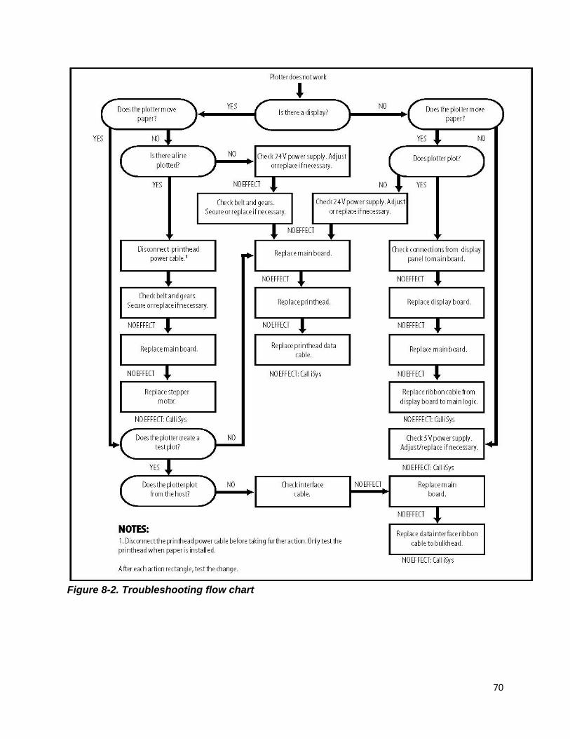
TROUBLESHOOTING 8.1 INTRODUCTION This chapter provides a list of problems that may be encountered with the V12, and gives possible causes and solutions for these problems. To use this chapter, examine the troubleshooting flow chart, or locate the problem from the list. Follow the steps in order, referring to Chapter 6, Maintenance and Repair, where necessary. Figures are shown in Chapter 7.
70
Figure 8-2. Troubleshooting flow chart
71
8.2 PROBLEMS Error message displayed: NO MEDIA Possible causes: Plotter has no paper or film.
Lid is not securely closed. Latch pins need adjustment. TOF/Media out sensor board defective.
Solutions: 1. Check the paper supply. Install more paper if necessary as described in Chapter 3, Installation. 2. Check that the paper is installed correctly and the plotter lid is securely closed. The top of the lid should be flush with the top of the side panels. 3. If the lid does not close securely or if the head pressure is too low this may cause a media out error. Adjust the latch pins as described in Chapter 6, Maintenance and Repair. 4. Replace TOF/Media out sensor board. Error message displayed: *_HOT!_* Cause: The thermal printhead is overheated. When the printhead temperature reaches 60ºC, the plotter stops plotting and asserts a “busy” signal to the host. Plotting resumes when the head temperature has cooled to 45ºC which will prevent printhead damage caused by overheating. Solution: Do not intervene. The plotter will resume plotting from where it left off with no loss of data when the printhead has cooled sufficiently. Plotter does not plot Possible causes: Lid is not securely closed. Latch pins need adjustment. Plot data is not reaching plotter. Plotter circuitry is malfunctioning. Solutions: 1. Check that the paper is installed correctly and the plotter lid is securely closed. The top of the lid should be flush with the top of the side panels. 2. If the lid does not close securely, or if the head pressure is too low, adjust the latch pins as described in Chapter 6, Maintenance and Repair. 3. Follow the flow chart to help identify the problem and take appropriate action. 4. Replace the main logic board as described in Chapter 6, Maintenance and Repair. 5. Replace the bulkhead data cable as described in Chapter 6, Maintenance and Repair.
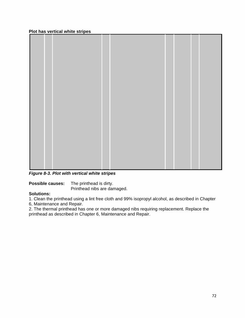
72
Plot has vertical white stripes
Figure 8-3. Plot with vertical white stripes Possible causes: The printhead is dirty. Printhead nibs are damaged. Solutions: 1. Clean the printhead using a lint free cloth and 99% isopropyl alcohol, as described in Chapter 6, Maintenance and Repair. 2. The thermal printhead has one or more damaged nibs requiring replacement. Replace the printhead as described in Chapter 6, Maintenance and Repair.
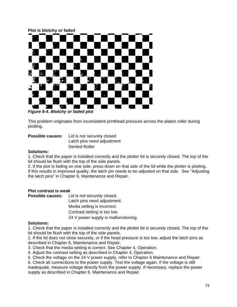
73
Plot is blotchy or faded
Figure 8-4. Blotchy or faded plot This problem originates from inconsistent printhead pressure across the platen roller during plotting. Possible causes: Lid is not securely closed Latch pins need adjustment Dented Roller Solutions: 1. Check that the paper is installed correctly and the plotter lid is securely closed. The top of the lid should be flush with the top of the side panels. 2. If the plot is fading on one side, press down on that side of the lid while the plotter is plotting. If this results in improved quality, the latch pin needs to be adjusted on that side. See “Adjusting the latch pins” in Chapter 6, Maintenance and Repair. Plot contrast is weak Possible causes: Lid is not securely closed. Latch pins need adjustment. Media setting is incorrect. Contrast setting is too low. 24 V power supply is malfunctioning. Solutions: 1. Check that the paper is installed correctly and the plotter lid is securely closed. The top of the lid should be flush with the top of the side panels. 2. If the lid does not close securely, or if the head pressure is too low, adjust the latch pins as described in Chapter 6, Maintenance and Repair. 3. Check that the media setting is correct. See Chapter 4, Operation. 4. Adjust the contrast setting as described in Chapter 4, Operation. 5. Check the voltage on the 24 V power supply, refer to Chapter 6 Maintenance and Repair. 6. Check all connections to the power supply. Test the voltage again. If the voltage is still inadequate, measure voltage directly from the power supply. If necessary, replace the power supply as described in Chapter 6, Maintenance and Repair.

74
Plot has black vertical lines
Figure 8-6. Plot with black vertical lines Cause: One or more bits in each byte going to the plotter is “stuck high” possibly due to a faulty cable. Solution: Run a test plot. If the lines are not present, the problem originates with the host data. If the lines are still present, the interface cable is faulty and must be replaced. See Chapter 3 for interface setup instructions. Plot is wrong length If you suspect that a plot is the wrong length, plot a job of a known length and measure it. Possible causes: Paper is not moving freely.
Scaling is incorrectly applied. Vertical emulation is incorrectly applied.
Solutions: 1. Check the paper feed path. Ensure that the paper is installed correctly and that the paper feed path is not obstructed. 2. Adjust or reset the scaling setting as described in Chapter 4, Operation. 3. Determine if your data requires a specific vertical emulation and adjust the vertical resolution setting appropriately. See “Vertical resolution” in Chapter 4, Operation.

75
Paper is wrinkling or tearing along one edge Possible causes: Paper feed is misaligned. Paper is incorrectly installed. Lid is not securely closed. Latch pins need adjustment. Solutions: 1. Ensure that paper is correctly aligned while feeding. If using fanfold paper, you may wish to obtain a fan fold paper tray from The Imaging Systems Group. 2. Check that the paper is installed correctly refers to “Media Installation” in Chapter 3, and that the plotter lid is securely closed. The top of the lid should be flush with the top of the side panels. 3. If the lid does not close securely, or if the head pressure is uneven, adjust the latch pins as described in Chapter 6, Maintenance and Repair. Plotter has no power Cause: If the plotter is plugged in to a functioning outlet, then the AC fuse has blown or the on/off switch has failed. Solution: Using a voltmeter check for voltage at the on/off switch AC input wires. If there is no voltage present at the input of the switch, replace the fuse as described in Chapter 6, Maintenance and Repair. Check for failed on/off switch, and replace if necessary as described in Chapter 6, Maintenance and Repair. Plotter display is functioning but motor does not function Cause: 24 volt power supply is malfunctioning. Broken drive belt. Main logic board failure. Solution: Check and if necessary, replace the 24 volt supply as described in Chapter 6, Maintenance and Repair. Check and if necessary, replace the motor drive belt as described in Chapter 6, Maintenance and Repair. Check and if necessary, replace the main logic board as described in Chapter 6, Maintenance and Repair. Changes cannot be made to control panel settings Cause: Plotter is in ONLINE mode. Solution: Press the ON/OFFLINE button. Plot output speed is erratic Cause: Plotter speed is set too high. This is most likely to occur on the 4.0 inch per second speed setting. Lowering the plot speed enables the plotter to match a lower rate of incoming data and produces a more steady output. Solution: Lower the plot speed setting on the control panel as described in Chapter 4. Form feed does not stop at top-of-form marks Cause: The top-of-form sensor is not sensing the marks. Solution: Adjust the top-of-form sensor potentiometer as described in Chapter 6, Maintenance and Repair.
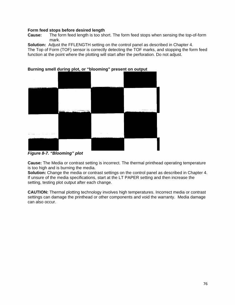
76
Form feed stops before desired length Cause: The form feed length is too short. The form feed stops when sensing the top-of-form
mark. Solution: Adjust the FFLENGTH setting on the control panel as described in Chapter 4. The Top of Form (TOF) sensor is correctly detecting the TOF marks, and stopping the form feed function at the point where the plotting will start after the perforation. Do not adjust. Burning smell during plot, or “blooming” present on output
Figure 8-7. “Blooming” plot Cause: The Media or contrast setting is incorrect. The thermal printhead operating temperature is too high and is burning the media. Solution: Change the media or contrast settings on the control panel as described in Chapter 4. If unsure of the media specifications, start at the LT PAPER setting and then increase the setting, testing plot output after each change. CAUTION: Thermal plotting technology involves high temperatures. Incorrect media or contrast settings can damage the printhead or other components and void the warranty. Media damage can also occur.
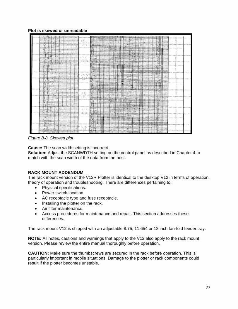
77
Plot is skewed or unreadable
Figure 8-8. Skewed plot Cause: The scan width setting is incorrect. Solution: Adjust the SCANWDTH setting on the control panel as described in Chapter 4 to match with the scan width of the data from the host. RACK MOUNT ADDENDUM The rack mount version of the V12R Plotter is identical to the desktop V12 in terms of operation, theory of operation and troubleshooting. There are differences pertaining to:
• Physical specifications. • Power switch location. • AC receptacle type and fuse receptacle. • Installing the plotter on the rack. • Air filter maintenance. • Access procedures for maintenance and repair. This section addresses these
differences. The rack mount V12 is shipped with an adjustable 8.75, 11.654 or 12 inch fan-fold feeder tray. NOTE: All notes, cautions and warnings that apply to the V12 also apply to the rack mount version. Please review the entire manual thoroughly before operation. CAUTION: Make sure the thumbscrews are secured in the rack before operation. This is particularly important in mobile situations. Damage to the plotter or rack components could result if the plotter becomes unstable.
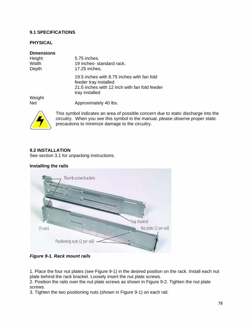
78
9.1 SPECIFICATIONS PHYSICAL Dimensions Height 5.75 inches. Width 19 inches- standard rack. Depth 17.25 inches. 19.5 inches with 8.75 inches with fan fold feeder tray installed 21.5 inches with 12 inch with fan fold feeder tray installed Weight Net Approximately 40 lbs.
This symbol indicates an area of possible concern due to static discharge into the circuitry. When you see this symbol in the manual, please observe proper static precautions to minimize damage to the circuitry.
9.2 INSTALLATION See section 3.1 for unpacking instructions. Installing the rails
Figure 9-1. Rack mount rails
1. Place the four nut plates (see Figure 9-1) in the desired position on the rack. Install each nut plate behind the rack bracket. Loosely insert the nut plate screws. 2. Position the rails over the nut plate screws as shown in Figure 9-2. Tighten the nut plate screws. 3. Tighten the two positioning nuts (shown in Figure 9-1) on each rail.
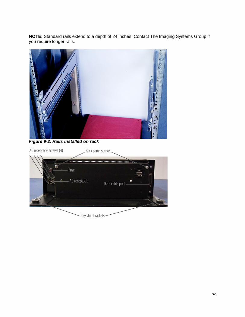
79
NOTE: Standard rails extend to a depth of 24 inches. Contact The Imaging Systems Group if you require longer rails.
Figure 9-2. Rails installed on rack
80
Installing the plotter on the rack 1. Loosen the tray stop bracket screws so the tray stop brackets are positioned as in Figure 9-3. 2. Slide the plotter tray into the tray channels on the rails. 3. Position the tray stop brackets over the tray channel brackets. Tighten the screws. CAUTION: Make sure the tray stop brackets are secured over the tray channel brackets. These brackets prevent the plotter from falling out of the rack if the front thumbscrews are loose. 1. If necessary, adjust the thumbscrew brackets- Figure 9-1 so that the thumbscrews can be tightened into them. 2. Tighten the thumbscrews into the brackets. Changing the interface line setting 1. Loosen the two thumbscrews on the front of the plotter. 2. Pull the drawer tray forward to access the back panel. 3. You may wish to remove the plotter from the rack for easier access. (If you do not wish to remove it, proceed to step 5.) Detach the AC cable and the data cable from the back of the plotter. 4. Loosen the tray stop bracket screws (see Figure 9-3) and move the brackets inwards. 5. Remove the two washered screws from the top left and top right of the back panel, shown in Figure 9-3. The back panel hinges down. Media installation Loosen the thumbscrews and pull the plotter forward. Install media. The fan-fold paper tray must be installed on the back of the plotter when using fan-fold paper. 9.3 MAINTENANCE AND REPAIR See Chapters 6 through 8 for maintenance, repair and troubleshooting procedures. Procedures that differ significantly from the desktop V12 are listed below. Removing the plotter from the rack 1. Loosen the two thumbscrews on the front of the plotter. 2. Pull the drawer tray forward. 3. Detach the AC cable and the data cable from the back of the plotter. 4. Loosen the tray stop bracket screws (see Figure 9-3) and move the brackets inwards. 5. Slide the plotter out of the rack. Reverse steps to reassemble.
81
Removing the side panels For certain procedures the side panels may be removed without removing the plotter from the rack. If in doubt, remove the plotter from the rack first. 1. Loosen the two thumbscrews on the front of the plotter. 2. Pull the drawer tray forward. 3. Remove the handle screws for the appropriate side. Remove the handle. 4. Open the plotter lid. Remove the two interior side panel screws from the appropriate side. 5. Remove the three bottom screws securing each side to the chassis. 6. Slide the side panels upwards to remove. Reverse steps to reassemble. Opening the back panel 1. Loosen the two thumbscrews on the front of the plotter. 2. Pull the drawer tray forward to access the back panel. 3. You may wish to remove the plotter from the rack for easier access. If you do not wish to remove it, proceed to step 5. Detach the AC cable and the data cable from the back of the plotter. 4. Loosen the tray stop bracket screws (see Figure 9-3) and move the brackets inwards. 5. Remove the two washered screws from the top left and top right of the back panel, shown in Figure 9-3. The back panel hinges down. Accessing the bottom of the plotter The plotter tray acts as the bottom panel of the plotter. You do not have to remove the plotter from the tray for most repair and maintenance procedures. Access the bottom of the plotter as follows: 1. Remove the plotter from the rack as described in this addendum. 2. Remove both side panels as described in this addendum. 3. Detach the power switch connections. 4. Detach the display board cable connections. CAUTION: To avoid damage to the plotter, detach the power switch connections and cable connections before raising the plotter off the tray. 5. Remove the six chassis screws. 6. Tilt the plotter chassis upwards to 90º to access the bottom. Reverse steps to reassemble. Cleaning the air filter Clean the air filter regularly. If you are operating the plotter in a dirty environment, frequently check the filter for cleanliness. A clogged filter will prevent the cooling fans from working effectively, and could contribute to the plotter overheating. 1. Remove the four phillips screws from the filter panel on the front of the plotter. 2. Remove the air filter from the panel. 3. Rinse the filter with clean water and squeeze out the excess. Repeat as necessary. Make sure the filter is dry before reinstalling. 4. Replace the filter in the panel and attach the panel to the plotter.
82
Replacing the display board 1. Remove the side panels as described in this addendum. 2. Detach the power switch connections. 3. Detach the display board cable connections. 4. Remove the air filter panel as described above. 5. Remove the three front panel screws. Remove the front panel. 6. Remove the two display board screws. 7. Detach the 5-pin connector. 8. Replace the display board and reverse steps to reassemble. Replacing the AC receptacle 1. Remove the plotter from the rack as described in this addendum. 2. Remove the side panels as described in this addendum. 3. Disconnect the load wire (black) connector from the fuse. 4. Access the bottom of the plotter as described in this addendum. 5. Remove the ground wire nut (shown in Figure 7-29) from the ground stud. 6. Remove the ground wires from the ground stud. 7. Remove the ground lug connector from the plotter tray. 8. Cut the cable ties for the wire harness leading from the AC receptacle to the power switch. 9. Remove the three P-straps securing the harness to the plotter. 10. Loosen the white AC receptacle wire by pulling it through to the receptacle. 11. Hinge the chassis down on to the plotter tray. 12. Remove the four AC receptacle screws shown in Figure 9-3. 13. Remove the AC receptacle and associated wiring. 14. Replace the AC receptacle and reverse steps to reassemble. Other repair procedures Follow the instructions in Chapters 6 and 7 of this manual, with the following substitutions:
• Remove the side panels as described in this addendum. • Access the bottom of the plotter as described in this addendum. • The fuse is located above the AC receptacle rather than beside it. Push, twist and pull to
remove. • The power switch is located at the front of the plotter. After removing the left side panel,
detach the four power switch connectors. Squeeze the sides of the power switch housing and push it through the front panel to remove.
• The bottom cooling fan has a metal housing for cooling efficiency. When replacing the fan, ensure this housing is installed.
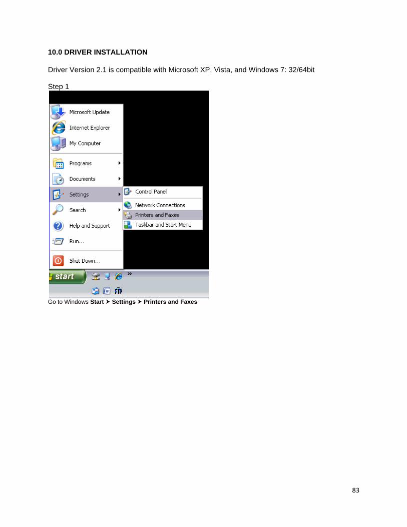
83
10.0 DRIVER INSTALLATION Driver Version 2.1 is compatible with Microsoft XP, Vista, and Windows 7: 32/64bit Step 1
Go to Windows Start Settings Printers and Faxes
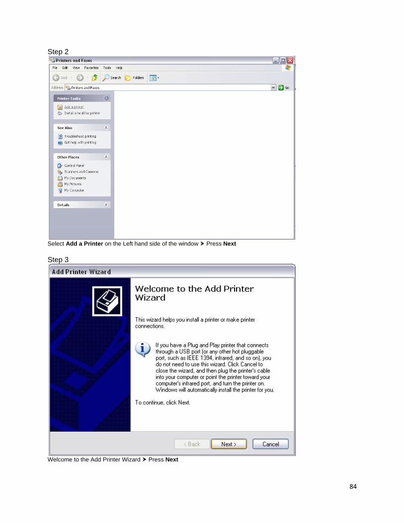
84
Step 2
Select Add a Printer on the Left hand side of the window Press Next Step 3
Welcome to the Add Printer Wizard Press Next
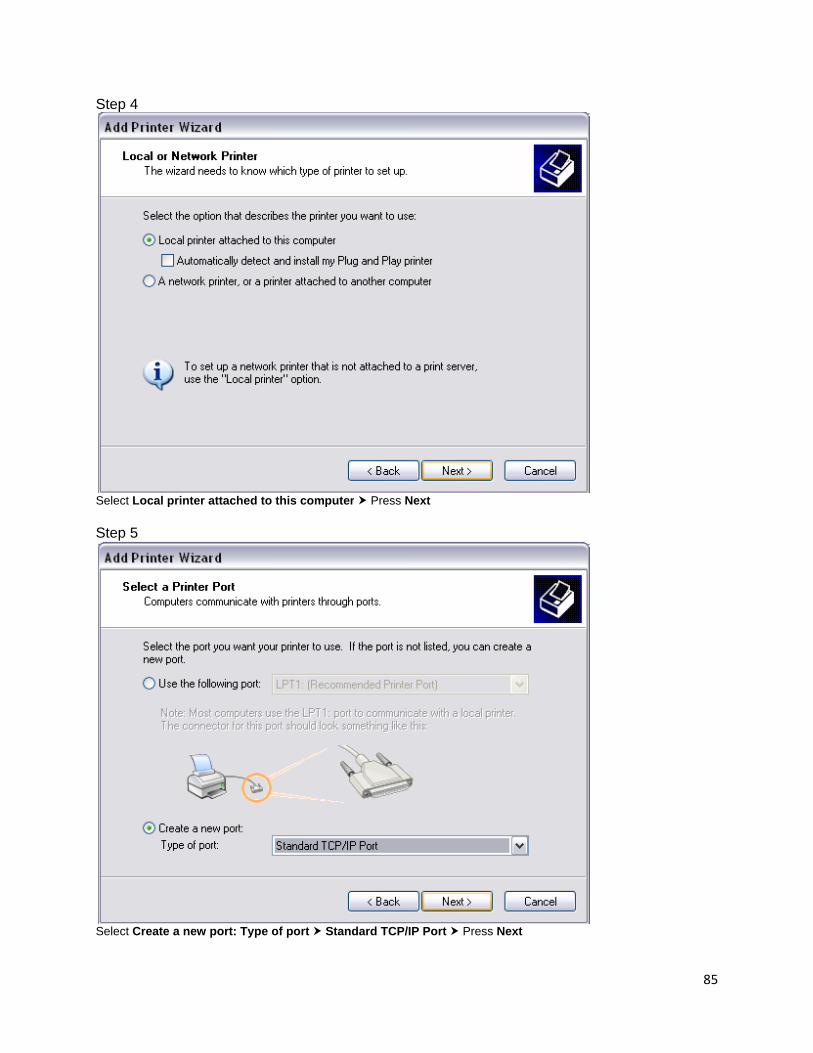
85
Step 4
Select Local printer attached to this computer Press Next Step 5
Select Create a new port: Type of port Standard TCP/IP Port Press Next
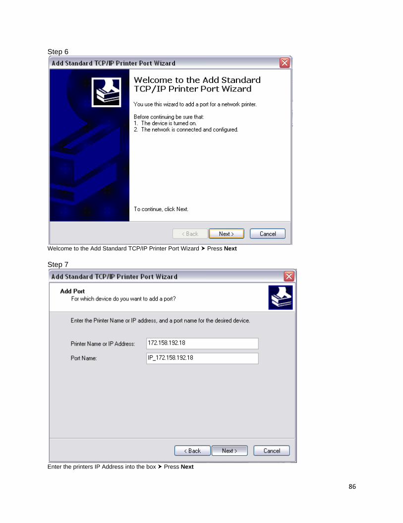
86
Step 6
Welcome to the Add Standard TCP/IP Printer Port Wizard Press Next Step 7
Enter the printers IP Address into the box Press Next
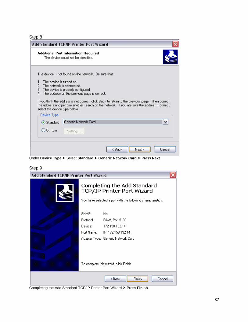
87
Step 8
Under Device Type Select Standard Generic Network Card Press Next Step 9
Completing the Add Standard TCP/IP Printer Port Wizard Press Finish
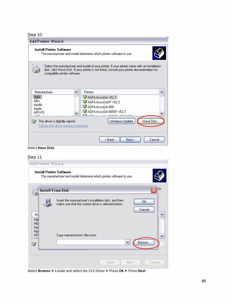
88
Step 10
Select Have Disk Step 11
Select Browse Locate and select the V12 Driver Press Ok Press Next

89
Step 12
Select the iSys V12 Printer Press Next Step 13
Enter the printer name Select yes if you would like the iSys V12 to be your default printer or no if you do not Press Next
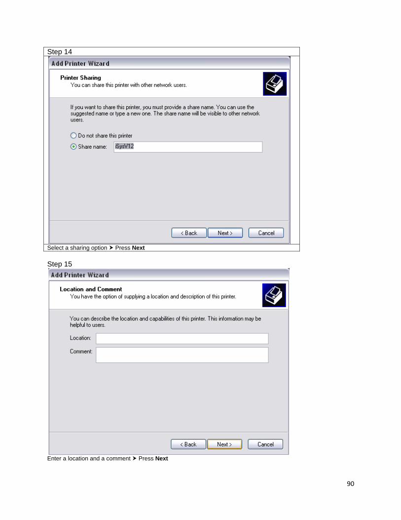
90
Step 14
Select a sharing option Press Next Step 15
Enter a location and a comment Press Next
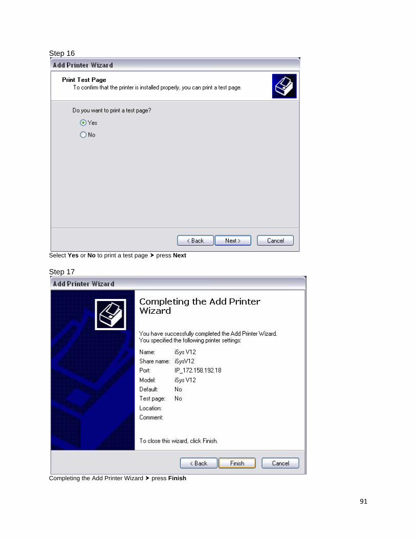
91
Step 16
Select Yes or No to print a test page press Next Step 17
Completing the Add Printer Wizard press Finish

92
APPENDIX
CENTRONICS INTERFACE HARDWARE If your plotter has a Centronics interface (Rev 5-0), please note that it can be connected to the short line interface only. Do not attempt to change the factory setting, or damage can result to the plotter, interface, host, or all three. The Rev 5-0 Centronics adapter card will allow reliable data transfers up to 40 feet using shielded cable. It will also accept either of the two data transfer formats described below automatically, without switches or jumpers. 1. To place the V12 in raster mode, the following 3 bytes (hexadecimal) must be sent to the Centronics adapter card: 1B, 2A, 00 Once these 3 bytes are sent, rastered plot data can be sent to the plotter at 216, 264 or 296 bytes per scan. The plotter byte per scan menu must be set on the front menu to match the input data bytes per scan. Refer to Chapter 4 Operations for information on control panel settings. Once the V12 Centronics card is set to raster mode it will remain in raster mode until the INIT line of the host Centronics port is pulsed or the plotter power is cycled. This will return the plotter to print mode. 2. Optionally a 6 byte (hexadecimal) header can be sent before each scan of rastered data. This header allows variable bytes/scan plotting. The format of the 6 byte header consists of: 1B, 2A, 72, XX, YY, 01 XX= high byte of the number of bytes per scan YY = low byte of the number of bytes per scan Example: to send a plot that is rastered to 200 bytes per scan, send the following 6 byte header before each and every scan of 200 bytes. 1B, 2A, 72, 00, C8, 01 00C8 hex = 200 decimal For a plot consisting of 264 bytes per scan, send 1B, 2A, 72, 01, 08, 01 0108 hex =264 decimal Other commands that can be sent to the V12 Centronics adapter: 1B, 41 Remote clear 1B, 42 Remote line terminate 1B, 43 Remote end of transmission 1B, 44 Remote form feed 1B, 45 Remote reset 1b, 50 <# of blanks> BLANK LINES (0x01 to 0xFF) The V12 plotter also obeys standard control characters which must be sent when the plotter is in print mode:

93
04 End of transmission 0A Line feed 0C Form feed NOTE: Print mode on the V12 means that all bytes that are received by the plotter are interpreted as ASCII characters and printed at 148 characters per line.
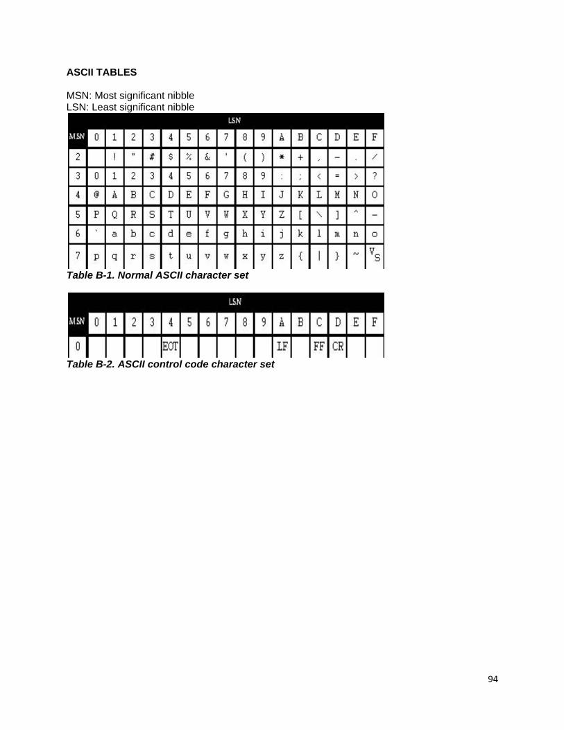
94
ASCII TABLES MSN: Most significant nibble LSN: Least significant nibble
Table B-1. Normal ASCII character set
Table B-2. ASCII control code character set
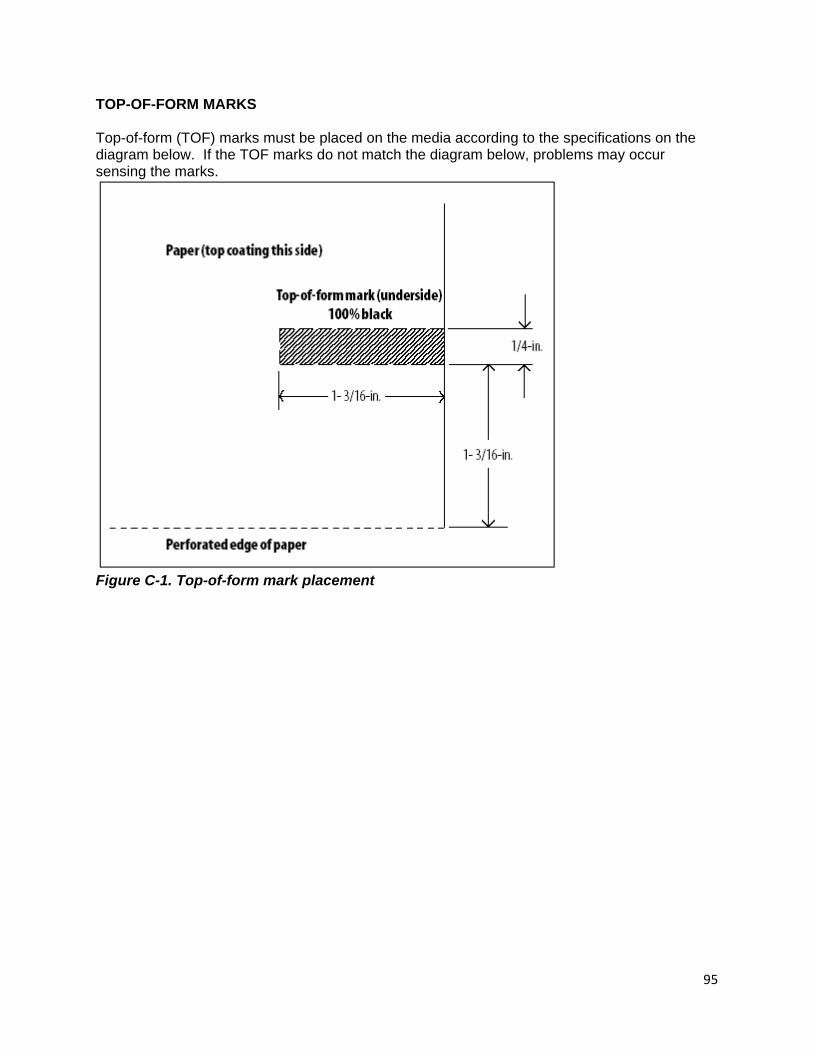
95
TOP-OF-FORM MARKS Top-of-form (TOF) marks must be placed on the media according to the specifications on the diagram below. If the TOF marks do not match the diagram below, problems may occur sensing the marks.
Figure C-1. Top-of-form mark placement
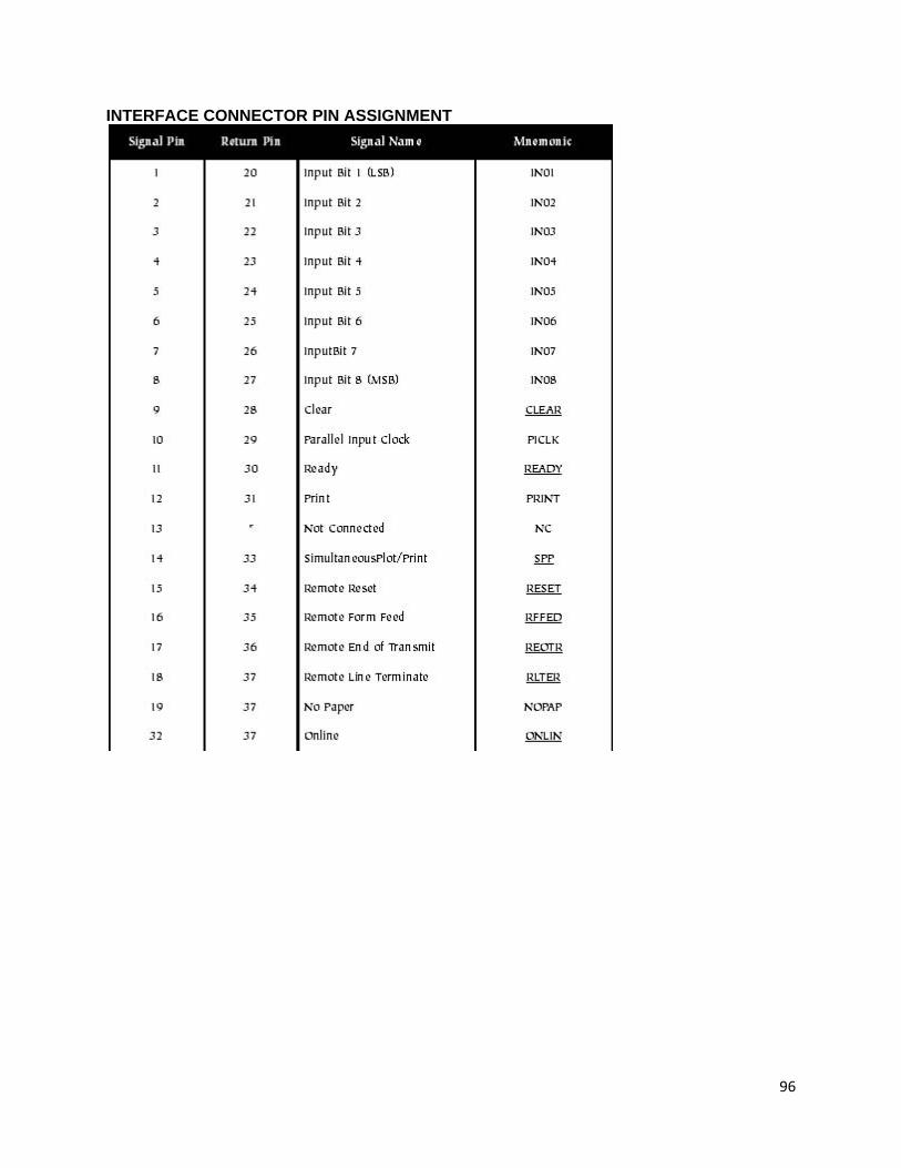
96
INTERFACE CONNECTOR PIN ASSIGNMENT