v17.1 - metaboxii preface r&tte directive this device is in compliance with the essential...
TRANSCRIPT

V17.1.10


Preface
NoticeThe company reserves the right to revise this publication or to change its contents without notice. Informationcontained herein is for reference only and does not constitute a commitment on the part of the manufacturer orany subsequent vendor. They assume no responsibility or liability for any errors or inaccuracies that may appearin this publication nor are they in anyway responsible for any loss or damage resulting from the use (or misuse)of this publication.This publication and any accompanying software may not, in whole or in part, be reproduced, translated, trans-mitted or reduced to any machine readable form without prior consent from the vendor, manufacturer or creatorsof this publication, except for copies kept by the user for backup purposes.Brand and product names mentioned in this publication may or may not be copyrights and/or registered trade-marks of their respective companies. They are mentioned for identification purposes only and are not intendedas an endorsement of that product or its manufacturer.©May 2017
Trademarks
Intel and Intel Core are trademarks/registered trademarks of Intel Corporation.
I

Preface
R&TTE DirectiveThis device is in compliance with the essential requirements and other relevant provisions of the R&TTE Direc-tive 1999/5/EC.
This device will be sold in the following EEA countries: Austria, Italy, Belgium, Liechtenstein, Denmark, Lux-embourg, Finland, Netherlands, France, Norway, Germany, Portugal, Greece, Spain, Iceland, Sweden, Ireland,United Kingdom, Cyprus, Czech Republic, Estonia, Hungary, Latvia, Lithuania, Malta, Slovakia, Poland, Slov-enia.
ErP Off Mode Power Consumption Statement:The figures below note the power consumption of this computer in compliance with European Commission (EC)regulations on power consumption in off mode:
• Off Mode < 0.5W
II

Preface
CE MarkingThis device has been tested to and conforms to the regulatory requirements of the European Union and has at-tained CE Marking. The CE Mark is a conformity marking consisting of the letters “CE”. The CE Mark appliesto products regulated by certain European health, safety and environmental protection legislation. The CE Markis obligatory for products it applies to: the manufacturer affixes the marking in order to be allowed to sell hisproduct in the European market.
This product conforms to the essential requirements of the R&TTE directive 1999/5/EC in order to attain CEMarking. A notified body has determined that this device has properly demonstrated that the requirements of thedirective have been met and has issued a favorable certificate of expert opinion. As such the device will bear thenotified body number 0560 after the CE mark.
The CE Marking is not a quality mark. Foremost, it refers to the safety rather than to the quality of a product.Secondly, CE Marking is mandatory for the product it applies to, whereas most quality markings are voluntary.
III
Preface
FCC Statement(Federal Communications Commission)You are cautioned that changes or modifications not expressly approved by the party responsible for compliancecould void the user's authority to operate the equipment.
This equipment has been tested and found to comply with the limits for a Class B digital device, pursuant to Part15 of the FCC Rules. These limits are designed to provide reasonable protection against harmful interference ina residential installation. This equipment generates, uses and can radiate radio frequency energy and, if not in-stalled and used in accordance with the instructions, may cause harmful interference to radio communications.However, there is no guarantee that interference will not occur in a particular installation. If this equipment doescause harmful interference to radio or television reception, which can be determined by turning the equipmentoff and on, the user is encouraged to try to correct the interference by one or more of the following measures:
• Re orient or relocate the receiving antenna.• Increase the separation between the equipment and receiver.• Connect the equipment into an outlet on a circuit different from that to which the receiver is connected.• Consult the service representative or an experienced radio/TV technician for help.
Operation is subject to the following two conditions:
1. This device may not cause interference.
And
2. This device must accept any interference, including interference that may cause undesired operation of the device.
IV

Preface
FCC RF Radiation Exposure Statement:
1. This Transmitter must not be co-located or operating in conjunction with any other antenna or transmitter.
2. This equipment complies with FCC RF radiation exposure limits set forth for an uncontrolled environment. This equipment should be installed and operated with a minimum distance of 20 centimeters between the radiator and your body.
Warning
Use only shielded cables to connect I/O devices to this equipment. You are cautioned that changes or modifications not ex-pressly approved by the manufacturer for compliance with the above standards could void your authority to operate theequipment.
V

Preface
IMPORTANT SAFETY INSTRUCTIONSFollow basic safety precautions, including those listed below, to reduce the risk of fire, electric shock, and injuryto persons when using any electrical equipment:
1. Do not use this product near water, for example near a bath tub, wash bowl, kitchen sink or laundry tub, in a wet basement or near a swimming pool.
2. Avoid using this equipment with a telephone line (other than a cordless type) during an electrical storm. There may be a remote risk of electrical shock from lightning.
3. Do not use the telephone to report a gas leak in the vicinity of the leak.4. Use only the power cord and batteries indicated in this manual. Do not dispose of batteries in a fire. They may
explode. Check with local codes for possible special disposal instructions.5. This product is intended to be supplied by a Listed Power Unit:
• Full Range AC/DC Adapter – AC in 100 - 240V, 50 - 60Hz DC Output 19.5V, 6.15A (120 Watts) minimum
VI
Preface
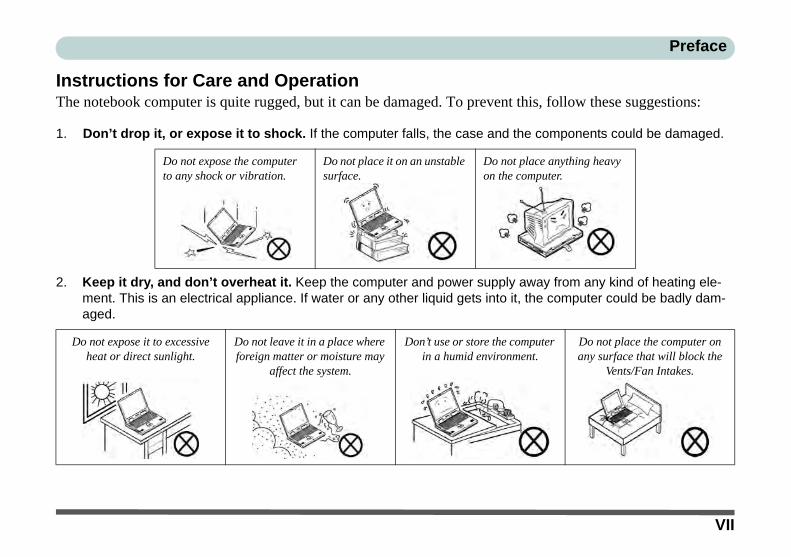
Instructions for Care and OperationThe notebook computer is quite rugged, but it can be damaged. To prevent this, follow these suggestions:
1. Don’t drop it, or expose it to shock. If the computer falls, the case and the components could be damaged.
2. Keep it dry, and don’t overheat it. Keep the computer and power supply away from any kind of heating ele-ment. This is an electrical appliance. If water or any other liquid gets into it, the computer could be badly dam-aged.
Do not expose the computer to any shock or vibration.
Do not place it on an unstable surface.
Do not place anything heavy on the computer.
Do not expose it to excessive heat or direct sunlight.
Do not leave it in a place where foreign matter or moisture may
affect the system.
Don’t use or store the computer in a humid environment.
Do not place the computer on any surface that will block the
Vents/Fan Intakes.
VII

Preface
3. Avoid interference. Keep the computer away from high capacity transformers, electric motors, and other strong magnetic fields. These can hinder proper performance and damage your data.
4. Follow the proper working procedures for the computer. Shut the computer down properly and don’t forget to save your work. Remember to periodically save your data as data may be lost if the battery is depleted.
5. Take care when using peripheral devices.
Do not turn off the power until you properly shut down all pro-grams.
Do not turn off any peripheral devices when the computer is on.
Do not disassemble the com-puter by yourself.
Perform routine maintenance on your computer.
Use only approved brands of peripherals.
Unplug the power cord before attaching peripheral devices.
VIII

Preface
ServicingDo not attempt to service the computer yourself. Doing so may violate your warranty and may expose you andthe computer to electric shock. Refer all servicing to authorized service personnel. Unplug the computer fromthe power supply. Then refer servicing to qualified service personnel under any of the following conditions:
• When the power cord or AC/DC adapter is damaged or frayed.• If the computer has been exposed to rain or other liquids.• If the computer does not work normally when you follow the operating instructions.• If the computer has been dropped or damaged (do not touch the poisonous liquid if the LCD panel breaks).• If there is an unusual odor, heat or smoke coming from your computer.
Bottom Cover Removal Warning
Users should not remove any cover(s) and /or screw(s) for the purposes of device upgrade as this may violate the terms ofyour warranty. If you need to replace/remove the hard disk/RAM/optical device etc., for any reason, please contact your dis-tributor/supplier for further information.
Removal Warning
When removing any cover(s) and screw(s) for the purposes of device upgrade, remember to replace the cover(s) andscrew(s) before restoring power to the system.
Also note the following when the cover is removed:
• Hazardous moving parts.• Keep away from moving fan blades.
IX

Preface
Power SafetyThe computer has specific power requirements:
• Only use a power adapter approved for use with this computer.• Your AC/DC adapter may be designed for international travel but it still requires a
steady, uninterrupted power supply. If you are unsure of your local power specifica-tions, consult your service representative or local power company.
• The power adapter may have either a 2-prong or a 3-prong grounded plug. The third prong is an important safety feature; do not defeat its purpose. If you do not have access to a compatible outlet, have a qualified electrician install one.
• When you want to unplug the power cord, be sure to disconnect it by the plug head, not by its wire.
• Make sure the socket and any extension cord(s) you use can support the total current load of all the connected devices.
• Before cleaning the computer, make sure it is disconnected from any external power supplies (i.e. AC/DC adapter or car adapter).
Do not plug in the power cord if you are wet.
Do not use the power cord if it is broken.
Do not place heavy objects on the power cord.
Power Safety Warning
Before you undertakeany upgrade proce-dures, make sure thatyou have turned off thepower, and disconnect-ed all peripherals andcables (including tele-phone lines and powercord).
You must also removeyour battery in order toprevent accidentallyturning the machine on.Before removing thebattery disconnect theAC/DC adapter fromthe computer.
X
Preface
Polymer/Lithium-Ion Battery PrecautionsNote the following information which is specific to Polymer/Lithium-Ion batteries only, and where applicable,this overrides the general battery precaution information overleaf.
• Polymer/Lithium-Ion batteries may experience a slight expansion or swelling, however this is part of the battery’s safety mechanism and is not a cause for concern.
• Use proper handling procedures when using Polymer/Lithium-Ion batteries. Do not use Polymer/Lithium-Ion batteries in high ambient temperature environments, and do not store unused batteries for extended periods.
• If you are working in areas of low temperature use the AC/DC adapter to power the computer.
See also the general battery precautionary information overleaf for further information.
XI

Preface
General Battery Precautions• Only use batteries designed for this computer. The wrong battery type may explode, leak or damage the computer.• Do not remove any batteries from the computer while it is powered on.• Do not continue to use a battery that has been dropped, or that appears damaged (e.g. bent or twisted) in any way. Even
if the computer continues to work with a damaged battery in place, it may cause circuit damage, which may possibly result in fire.
• If you do not use the battery for an extended period, then remove the battery from the computer for storage.• Recharge the batteries using the notebook’s system. Incorrect recharging may make the battery explode.• Do not try to repair a battery pack. Refer any battery pack repair or replacement to your service representative or qual-
ified service personnel.• Keep children away from, and promptly dispose of a damaged battery. Always dispose of batteries carefully. Batteries
may explode or leak if exposed to fire, or improperly handled or discarded.• Keep the battery away from metal appliances.• Affix tape to the battery contacts before disposing of the battery.• Do not touch the battery contacts with your hands or metal objects.
Battery Disposal & Caution
The product that you have purchased contains a rechargeable battery. The battery is recyclable. At the end of its useful life,under various state and local laws, it may be illegal to dispose of this battery into the municipal waste stream. Check withyour local solid waste officials for details in your area for recycling options or proper disposal.
Danger of explosion if battery is incorrectly replaced. Replace only with the same or equivalent type recommended by themanufacturer. Discard used battery according to the manufacturer’s instructions.
XII
Preface
CleaningDo not apply cleaner directly to the computer; use a soft clean cloth. Do not use volatile (petroleum distillates) or abrasive cleaners on any part of the computer.
Travel ConsiderationsAs you get ready for your trip, run through this list to make sure the system is ready to go:
1. Check that the battery pack and any spares are fully charged.2. Power off the computer and peripherals.3. Close the display panel and make sure it’s latched.4. Disconnect the AC/DC adapter and cables. Stow them in the carrying bag. 5. The AC/DC adapter uses voltages from 100 to 240 volts so you won’t need a second voltage adapter. However,
check with your travel agent to see if you need any socket adapters.6. Put the notebook in its carrying bag and secure it with the bag’s straps.7. If you’re taking any peripherals (e.g. a printer, mouse or digital camera), pack them and those devices’ adapters
and/or cables.8. Anticipate customs - Some jurisdictions may have import restrictions or require proof of ownership for both hard-
ware and software. Make sure your “papers” are handy.
Power Off Before Traveling
Make sure that your notebook is completely powered off before putting it into a travel bag (or any such container). Putting anotebook which is powered on in a travel bag may cause the Vents/Fan Intakes to be blocked. To prevent your computerfrom overheating make sure nothing blocks the Vent/Fan Intakes while the computer is in use.
XIII

Preface
PackingAs you get ready for your trip, run through this list to make sure the system is ready to go:
1. Check that the battery pack and any spares are fully charged.2. Power off the computer and peripherals.3. Close the display panel and make sure it’s latched.4. Disconnect the AC/DC adapter and cables. Stow them in the carrying bag. 5. The AC/DC adapter uses voltages from 100 to 240 volts so you won’t need a second voltage adapter. However,
check with your travel agent to see if you need any socket adapters.6. Put the notebook in its carrying bag and secure it with the bag’s straps.7. If you’re taking any peripherals (e.g. a printer, mouse or digital camera), pack them and those devices’ adapters
and/or cables.8. Anticipate customs - Some jurisdictions may have import restrictions or require proof of ownership for both
hardware and software. Make sure your documents are prepared.
Power Off Before Traveling
Make sure that your notebook is completely powered off before putting it into a travel bag (or any such container). Putting anotebook which is powered on in a travel bag may cause the vent(s)/fan intake(s)/outlet(s) to be blocked. To prevent yourcomputer from overheating make sure nothing blocks the vent(s)/fan intake(s)/outlet(s) while the computer is in use.
XIV

Preface
On the RoadIn addition to the general safety and maintenance suggestions in this preface, and Chapter 8: Troubleshooting,keep these points in mind:
Hand-carry the notebook - For security, don’t let it out of your sight. In some areas, computer theft is verycommon. Don’t check it with “normal” luggage. Baggage handlers may not be sufficiently careful. Avoid knock-ing the computer against hard objects.
Beware of Electromagnetic fields - Devices such as metal detectors & X-ray machines can damage the com-puter, hard disk, floppy disks, and other media. They may also destroy any stored data - Pass your computer anddisks around the devices. Ask security officials to hand-inspect them (you may be asked to turn it on). Note:Some airports also scan luggage with these devices.
Fly safely - Most airlines have regulations about the use of computers and other electronic devices in flight.These restrictions are for your safety, follow them. If you stow the notebook in an overhead compartment, makesure it’s secure. Contents may shift and/or fall out when the compartment is opened.
Get power where you can - If an electrical outlet is available, use the AC/DC adapter and keep your battery(ies)charged.
Keep it dry - If you move quickly from a cold to a warm location, water vapor can condense inside the computer.Wait a few minutes before turning it on so that any moisture can evaporate.
XV

Preface
Developing Good Work HabitsDeveloping good work habits is important if you need to work in front of the computer for long periods of time.Improper work habits can result in discomfort or serious injury from repetitive strain to your hands, wrists orother joints. The following are some tips to reduce the strain:
• Adjust the height of the chair and/or desk so that the keyboard is at or slightly below the level of your elbow. Keep your forearms, wrists, and hands in a relaxed position.
• Your knees should be slightly higher than your hips. Place your feet flat on the floor or on a footrest if necessary.
• Use a chair with a back and adjust it to support your lower back comfortably.• Sit straight so that your knees, hips and elbows form approximately 90-degree angles
when you are working.• Take periodic breaks if you are using the computer for long periods of time.
Remember to:• Alter your posture frequently.• Stretch and exercise your body several times a day.• Take periodic breaks when you work at the computer for long periods of time. Frequent
and short breaks are better than fewer and longer breaks.
XVI

Preface
LightingProper lighting and a comfortable viewing angle can reduce eye strain and shoulder and neck muscle fatigue.
• Position the display to avoid glare or reflections from overhead lighting or outside sources of light.• Keep the display screen clean and set the brightness and contrast to levels that allow you to see the screen clearly.• Position the display directly in front of you at a comfortable viewing distance.• Adjust the display-viewing angle to find the best position.
LCD Screen CareTo prevent image persistence on LCD monitors (caused by the continuous display of graphics on the screen foran extended period of time) take the following precautions:
• Set the Windows Power Plans to turn the screen off after a few minutes of screen idle time.• Use a rotating, moving or blank screen saver (this prevents an image from being displayed too long).• Rotate desktop background images every few days.• Turn the monitor off when the system is not in use.
LCD Electro-Plated LogosNote that in computers featuring a raised LCD electro-plated logo, the logo is covered by a protective adhesive.Due to general wear and tear, this adhesive may deteriorate over time and the exposed logo may develop sharpedges. Be careful when handling the computer in this case, and avoid touching the raised LCD electro-platedlogo. Avoid placing any other items in the carrying bag which may rub against the top of the computer duringtransport. If any such wear and tear develops contact your distributor/supplier.
XVII

Preface
XVIII
Preface
ContentsNotice .............................................................................................................................................................IErP Off Mode Power Consumption Statement: ........................................................................................... IIFCC Statement ............................................................................................................................................IVFCC RF Radiation Exposure Statement: .....................................................................................................VInstructions for Care and Operation ......................................................................................................... VIIServicing .....................................................................................................................................................IXPower Safety ................................................................................................................................................XPolymer/Lithium-Ion Battery Precautions ..................................................................................................XIGeneral Battery Precautions ..................................................................................................................... XIICleaning ...................................................................................................................................................XIIITravel Considerations ..............................................................................................................................XIII
Quick Start GuideOverview ....................................................................................................................................................1-1Advanced Users .........................................................................................................................................1-2Beginners and Not-So-Advanced Users ....................................................................................................1-2Warning Boxes ..........................................................................................................................................1-2Not Included ..............................................................................................................................................1-3System Software ........................................................................................................................................1-4System Startup ...........................................................................................................................................1-5Model Differences .....................................................................................................................................1-6
XIX

Preface
LCD Panel Open - Model A ......................................................................................................................1-7LCD Panel Open - Model B ......................................................................................................................1-8LCD Panel Open - Model C ......................................................................................................................1-9LED Indicators .........................................................................................................................................1-10Illuminated White LED Keyboard ...........................................................................................................1-11Illuminated Color LED Keyboard ...........................................................................................................1-12Keyboard Application Settings ................................................................................................................1-13Control Center .........................................................................................................................................1-14Keyboard Backlight LED ........................................................................................................................1-15Flexikey® Application ............................................................................................................................1-21Flexikey® Application Features: .............................................................................................................1-22Keyboard Shortcuts .................................................................................................................................1-23Function Keys & Visual Indicators .........................................................................................................1-24Front & Rear Views - All Models ...........................................................................................................1-25Right Views .............................................................................................................................................1-26Left Views ...............................................................................................................................................1-273G/4G Module USIM Card Installation (for Models A & B) .................................................................1-29Bottom View - Model A ..........................................................................................................................1-32Bottom View - Model B ..........................................................................................................................1-33Bottom View - Model C ..........................................................................................................................1-34Windows 10 Start Menu ..........................................................................................................................1-35Right-Clicking the Windows Logo In Start Menu ..................................................................................1-36
XX
Preface
Start Menu Apps & Tiles .........................................................................................................................1-37Windows 10 Control Panel ......................................................................................................................1-39Settings ....................................................................................................................................................1-40Windows 10 Taskbar ...............................................................................................................................1-41Video Features .........................................................................................................................................1-42Microsoft Hybrid Graphics ......................................................................................................................1-42Power Options .........................................................................................................................................1-47
Storage Devices, Mouse, & AudioOverview ....................................................................................................................................................2-1Hard Disk Drive/Solid State Drive ............................................................................................................2-2Multi-in-1 Card Reader ..............................................................................................................................2-3Audio Features ...........................................................................................................................................2-4Setup for Audio Recording ........................................................................................................................2-5Touchpad and Buttons/Mouse ...................................................................................................................2-6Touchpad Sensitivity .................................................................................................................................2-6Mouse Properties Control Panel ................................................................................................................2-7Mouse & Touchpad Devices .....................................................................................................................2-9
Power ManagementOverview ....................................................................................................................................................3-1The Power Sources ....................................................................................................................................3-2AC/DC Adapter .........................................................................................................................................3-2
XXI
Preface
Battery ........................................................................................................................................................3-2Turning On the Computer ..........................................................................................................................3-3Shutting the Computer Down ....................................................................................................................3-4Power Plans ...............................................................................................................................................3-5Power-Saving States ..................................................................................................................................3-7Sleep ..........................................................................................................................................................3-7Hibernate ....................................................................................................................................................3-8Shut down ..................................................................................................................................................3-8Configuring the Power Buttons .................................................................................................................3-9Resuming Operation ................................................................................................................................3-11Power Conservation Modes .....................................................................................................................3-12Settings Menu Power Controls ................................................................................................................3-14Battery Information .................................................................................................................................3-17Battery Power ..........................................................................................................................................3-17Conserving Battery Power .......................................................................................................................3-18Battery Life ..............................................................................................................................................3-19New Battery .............................................................................................................................................3-19Recharging the Battery with the AC/DC Adapter ...................................................................................3-19Proper handling of the Battery Pack ........................................................................................................3-20Battery FAQ .............................................................................................................................................3-21
XXII

Preface
Drivers & UtilitiesWhat to Install ............................................................................................................................................4-1Module Driver Installation ........................................................................................................................4-1Driver Installation ......................................................................................................................................4-2Updating/Reinstalling Individual Drivers ..................................................................................................4-5User Account Control ................................................................................................................................4-6Windows Security Message .......................................................................................................................4-6New Hardware Found ................................................................................................................................4-6Driver Installation Procedure .....................................................................................................................4-7Chipset .......................................................................................................................................................4-7Video (VGA) .............................................................................................................................................4-7NVIDIA Video (VGA) ..............................................................................................................................4-7LAN ...........................................................................................................................................................4-7Card Reader ...............................................................................................................................................4-7Touchpad ...................................................................................................................................................4-8Airplane .....................................................................................................................................................4-8Control Center ...........................................................................................................................................4-8MEI Driver .................................................................................................................................................4-8Audio .........................................................................................................................................................4-8Optional Drivers ......................................................................................................................................4-10
XXIII

Preface
BIOS UtilitiesOverview ....................................................................................................................................................5-1The Power-On Self Test (POST) ...............................................................................................................5-2Failing the POST .......................................................................................................................................5-3Fatal Errors ................................................................................................................................................5-3Non-Fatal Errors ........................................................................................................................................5-3The Setup Utility ........................................................................................................................................5-4Entering Setup ...........................................................................................................................................5-4Setup Screens .............................................................................................................................................5-5Main Menu .................................................................................................................................................5-6SATA Port # (Main Menu) ........................................................................................................................5-6OffBoard SATA/NVme Controller Configuration (Main Menu) .............................................................5-7System Time & Date (Main Menu) ...........................................................................................................5-7ME FW Version/System/Extended Memory (Main Menu) ......................................................................5-7MB Series/BIOS Revision/KBC/EC firmware Revision/Mac Address (Main Menu) ..............................5-7Advanced Menu .........................................................................................................................................5-8Advanced Chipset Control (Advanced Menu) ..........................................................................................5-8GPU Performance Scaling (Advanced Menu > Advanced Chipset Control) ............................................5-8FlexiCharger (Advanced Menu > Advanced Chipset Control) .................................................................5-9Software Guard Extensions (Advanced Menu > Advanced Chipset Control) ..........................................5-9VT-d (Advanced Menu > Advanced Chipset Control) ..............................................................................5-9SATA Mode (Advanced Menu) ..............................................................................................................5-10
XXIV

Preface
Power On Boot Beep (Advanced Menu) .................................................................................................5-10Battery Low Alarm Beep (Advanced Menu) ...........................................................................................5-10Security Menu ..........................................................................................................................................5-11Set Supervisor Password (Security Menu) ..............................................................................................5-11Set User Password (Security Menu) ........................................................................................................5-12Password on boot: (Security Menu) ........................................................................................................5-12Secure Boot Control (Security Menu) .....................................................................................................5-13TPM Configuration (Security Menu) ......................................................................................................5-14Boot Menu ...............................................................................................................................................5-15Boot Option Priorities (Boot Menu) ........................................................................................................5-16UEFI Boot (Boot Menu) ..........................................................................................................................5-16Exit Menu ................................................................................................................................................5-17
ModulesOverview ....................................................................................................................................................6-1Setting Up SATA Mode (Optane™ or AHCI) ..........................................................................................6-2AHCI Mode ...............................................................................................................................................6-2Intel® Optane™ ........................................................................................................................................6-2Intel® Rapid Storage Technology Application .........................................................................................6-2Intel® Optane™ Setup Procedure .............................................................................................................6-3Clearing Intel® Optane™ ..........................................................................................................................6-7Wireless LAN Module .............................................................................................................................6-10
XXV

Preface
Intel® WLAN Driver Installation ............................................................................................................6-10WLAN Configuration in Windows 10 ....................................................................................................6-11Fingerprint Reader Module ......................................................................................................................6-14Fingerprint Reader Driver Installation .....................................................................................................6-14Fingerprint Module Configuration ..........................................................................................................6-15Bluetooth & WLAN Combo Module ......................................................................................................6-17Intel Bluetooth Combo Driver Installation ..............................................................................................6-18Bluetooth Configuration in Windows ......................................................................................................6-19To Make your Computer Discoverable to Bluetooth Devices .................................................................6-21Intel® Software Guard Extensions Driver ...............................................................................................6-22Intel SGX Driver Installation ...................................................................................................................6-22Intel® Rapid Storage Technology ...........................................................................................................6-23IRST Driver Installation ..........................................................................................................................6-23Intel® Rapid Storage Technology for Optane Systems ...........................................................................6-24Enabling Intel® Optane™ .......................................................................................................................6-25Disabling Intel® Optane™ ......................................................................................................................6-28Sound Blaster Cinema 3 ..........................................................................................................................6-30Sound Blaster Cinema 3 Installation .......................................................................................................6-30Sound Blaster Cinema 3 Application ......................................................................................................6-31Sound Blaster Cinema 3 SBX Pro Studio ................................................................................................6-37PC Camera ...............................................................................................................................................6-42Camera App .............................................................................................................................................6-43
XXVI

Preface
Taking Pictures/Capturing Video ............................................................................................................6-45Trusted Platform Module .........................................................................................................................6-47Enabling & Managing TPM ....................................................................................................................6-48TPM Management in Windows ...............................................................................................................6-49TPM Actions ............................................................................................................................................6-513G/4G Module .........................................................................................................................................6-533G/4G Configuration in Windows 10 ......................................................................................................6-57
TroubleshootingOverview ....................................................................................................................................................7-1Basic Hints and Tips ..................................................................................................................................7-2Backup and General Maintenance .............................................................................................................7-3Viruses .......................................................................................................................................................7-4Upgrading and Adding New Hardware/Software ......................................................................................7-5Problems and Possible Solutions ...............................................................................................................7-7Resolving the “Can’t connect to this network” issue with the 3G/4G Module .......................................7-16Intel® Optane™ Notes ............................................................................................................................7-17
Interface (Ports & Jacks)Overview ...................................................................................................................................................A-1Ports and Jacks ..........................................................................................................................................A-2Card Reader ..............................................................................................................................................A-2DC-In Jack ................................................................................................................................................A-2
XXVII

Preface
External Monitor (VGA) Port ...................................................................................................................A-2HDMI-Out Port .........................................................................................................................................A-2Headphone-Out Jack .................................................................................................................................A-2Microphone-In Jack ..................................................................................................................................A-3Mini DisplayPort 1.2 ................................................................................................................................A-3RJ-45 LAN Jack .......................................................................................................................................A-3Security Lock Slot ....................................................................................................................................A-3USB 2.0/1.1 Port .......................................................................................................................................A-4USB 3.0 (USB 3.1 Gen 1 Type A) Port ....................................................................................................A-4USB 3.0 (USB 3.1 Gen 1 Type C) Port ....................................................................................................A-4USB 3.1 (USB 3.1 Gen 2 Type A & Type C) Port (Factory Option) .......................................................................................................................................A-4
Control Center & Flexikey®Overview ...................................................................................................................................................B-1Control Center ..........................................................................................................................................B-1Flexikey® .................................................................................................................................................B-1Power Modes ............................................................................................................................................B-3Control Center Menus ...............................................................................................................................B-4Power Status (System Program) .............................................................................................................B-5Brightness (System Program) ..................................................................................................................B-5Volume (System Program) .......................................................................................................................B-5
XXVIII

Preface
Fan Speed (System Program) ...................................................................................................................B-5This system supports Power Saving power .........................................................................................B-6Sleep Button (System Program) ..............................................................................................................B-6Desktop Background (System Program) .................................................................................................B-6Display Switch (System Program) ...........................................................................................................B-6Time Zone (System Program) .................................................................................................................B-6Backlight Keyboard (Device) ...................................................................................................................B-7TouchPad/Camera (Device) .....................................................................................................................B-7Caps Lock/Scroll Lock/ Number Lock/Airplane Mode ...........................................................................B-7Left Windows Key (Gaming) ..................................................................................................................B-7Flexikey® (Gaming) .................................................................................................................................B-7Flexikey® Application .............................................................................................................................B-8Language Interface ...................................................................................................................................B-9Keyboard Settings - Express Key ...........................................................................................................B-13Enabling Time Record ............................................................................................................................B-15Keyboard Settings - Launch App ...........................................................................................................B-17Keyboard Settings - Express Text ..........................................................................................................B-19Keyboard Settings - Disable ...................................................................................................................B-21Mouse Settings - Express Key ................................................................................................................B-22Enabling Time Record for Mouse Settings ............................................................................................B-23Mouse Settings - Launch App ................................................................................................................B-24Mouse Settings - Express Text ...............................................................................................................B-26
XXIX

Preface
Mouse Settings - Disable ........................................................................................................................B-28Statistics ..................................................................................................................................................B-29
Video Driver ControlsVideo Driver Installation ..........................................................................................................................C-1Video (VGA) ............................................................................................................................................C-1NVIDIA Video (VGA) .............................................................................................................................C-1Microsoft Hybrid Graphics .......................................................................................................................C-2Intel® Dynamic Video Memory Technology ...........................................................................................C-4Configure Other Displays Using Project ..................................................................................................C-5Configuring an External Display In Windows .........................................................................................C-6HDMI Audio Configuration .....................................................................................................................C-7Wireless Display .....................................................................................................................................C-10Wireless Display Configuration .............................................................................................................C-11Intel® HD Graphics Control Panel .........................................................................................................C-13Display Devices & Options ....................................................................................................................C-26Attaching Other Displays .......................................................................................................................C-27NVIDIA Control Panel ...........................................................................................................................C-30Customization Options ...........................................................................................................................C-33Configure Surround, PhysX® .................................................................................................................C-37NVIDIA GeForce Experience ................................................................................................................C-38
XXX

Preface
SpecificationsCore Logic ................................................................................................................................................D-2Display ......................................................................................................................................................D-2Memory .....................................................................................................................................................D-2Storage ......................................................................................................................................................D-2BIOS .........................................................................................................................................................D-2Audio ........................................................................................................................................................D-2Keyboard & Pointing Device ....................................................................................................................D-2Indicators ..................................................................................................................................................D-2Interface ....................................................................................................................................................D-2Card Reader ..............................................................................................................................................D-3Slots ..........................................................................................................................................................D-3Communication .........................................................................................................................................D-3Operating System ......................................................................................................................................D-3Features (Depends on Model Type) .........................................................................................................D-3Security .....................................................................................................................................................D-3Power Management ..................................................................................................................................D-4Power ........................................................................................................................................................D-4Environmental Spec ..................................................................................................................................D-4Physical Dimensions & Weight ................................................................................................................D-4
XXXI

Preface
XXXII

Quick Start Guide 1
Chapter 1: Quick Start Guide
OverviewThis Quick Start Guide is a brief introduction to the basic features of your computer, to navigating around thecomputer and to getting your system started. The remainder of the manual covers the following:
• Chapter 2 A guide to using some of the main features of the computer e.g. the storage devices (hard disk and card reader), TouchPad & Mouse and Audio Features.
• Chapter 3 The computer’s power management options.• Chapter 4 The installation of the drivers and utilities essential to the operation or improvement of some of the
computer’s subsystems.• Chapter 5 An outline of the computer’s built-in software or BIOS (Basic Input Output System).• Chapter 6 A quick guide to the computer’s PC Camera, Wireless LAN, Bluetooth & WLAN Combo,
Sound Blaster Audio and Intel modules (some of which may be optional depending on your pur-chase configuration).
• Chapter 7 A troubleshooting guide.• Appendix A Definitions of the interface, ports/jacks which allow your computer to communicate with external
devices.• Appendix B Information on the Control Center.• Appendix C Information on the Video driver controls.• Appendix D The computer’s specification.
Overview 1 - 1
Quick Start Guide1
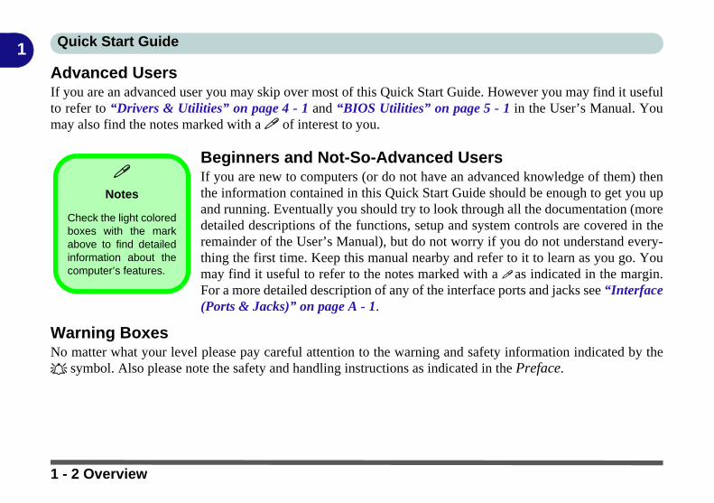
Advanced UsersIf you are an advanced user you may skip over most of this Quick Start Guide. However you may find it usefulto refer to “Drivers & Utilities” on page 4 - 1 and “BIOS Utilities” on page 5 - 1 in the User’s Manual. Youmay also find the notes marked with a of interest to you.Beginners and Not-So-Advanced UsersIf you are new to computers (or do not have an advanced knowledge of them) thenthe information contained in this Quick Start Guide should be enough to get you upand running. Eventually you should try to look through all the documentation (moredetailed descriptions of the functions, setup and system controls are covered in theremainder of the User’s Manual), but do not worry if you do not understand every-thing the first time. Keep this manual nearby and refer to it to learn as you go. Youmay find it useful to refer to the notes marked with a as indicated in the margin.For a more detailed description of any of the interface ports and jacks see “Interface(Ports & Jacks)” on page A - 1.
Warning BoxesNo matter what your level please pay careful attention to the warning and safety information indicated by the symbol. Also please note the safety and handling instructions as indicated in the Preface.
Notes
Check the light coloredboxes with the markabove to find detailedinformation about thecomputer’s features.
1 - 2 Overview

Quick Start Guide 1
Not IncludedOperating Systems (e.g. Windows 10) and applications (e.g. word processing, spreadsheet and database pro-grams) have their own manuals, so please consult the appropriate manuals.Drivers
If you are installing new system software, or are re-configuring your computer for a different system, you will need to installthe appropriate drivers. Drivers are programs which act as an interface between the computer and a hardware componente.g. a wireless network module. It is very important that you install the drivers in the order listed in Table 4 - 1, on page 4- 4. You will be unable to use most advanced controls until the necessary drivers and utilities are properly installed. If yoursystem hasn’t been properly configured (your service representative may have already done that for you), refer to “Drivers& Utilities” on page 4 - 1 for installation instructions.
Ports and Jacks
See “Ports and Jacks” on page A - 2 for a description of the interface (ports & jacks) which allow your computer to com-municate with external devices, connect to the internet etc.
Overview 1 - 3

Quick Start Guide1
System SoftwareYour computer may already come with system software pre-installed. Where this is not the case, or where youare re-configuring your computer for a different system, you will find the Windows 10 (64-bit) operating systemis supported.Windows OS
Note that the information included on the following pages is for Windows 10 only.
In order to run Windows 10 (64-bit) your computer requires a minimum 4GB of system memory (RAM).
1 - 4 Overview

Quick Start Guide 1
System Startup1. Remove all packing materials, and place the computer on a stable surface, and securely attach any peripherals you want to
use with the notebook (e.g. keyboard and mouse) to their ports.2. Attach the AC/DC adapter to the DC-In jack on the left of the computer, then plug the AC power cord into an outlet, and
connect the AC power cord to the AC/DC adapter (make sure you use the adapter when first setting up the computer, as to safeguard the computer during shipping, the battery will be locked to not power the system until first connected to the AC/DC adapter).
3. Use one hand to raise the lid/LCD to a comfortable viewing angle (it is preferable not to exceed 135 degrees); use the other hand to support the base of the computer (Note: Never lift the computer by the lid/LCD).
4. Press the power button on the top of the computer for about 2 - 3 seconds to turn the computer “on” (note that the power LED on the front of the computer will turn from orange to green when the computer powers on).
135° Shutdown
Note that you shouldalways shut yourcomputer down bychoosing the ShutDown command inWindows (see page1 - 47). This will helpprevent hard disk orsystem problems.Figure 1 - 1 - AC/DC Adapter In / Opening the Lid/LCD
135°
System Startup 1 - 5

Quick Start Guide1
Model DifferencesThis notebook series includes three different models that vary slightly in design style, color and general appear-ance. Note that though your computer may look slightly different from that pictured throughout this manual, allports, jacks (other than those indicated below and in specification) and general functions are the same for all thedesign styles (see Appendix D for further details).Table 1 - 1 - Model Differences
Feature Model A Model B Model C
3G/4G Module Supported Not Supported
Fingerprint Reader Supported Not Supported Supported
Display 15.6" (39.62cm) 16:9 Panel 17.3" (43.94cm) 16:9 Panel
Design
1 - 6 System Startup

Quick Start Guide 1
LCD Panel Open - Model A Figure 1 - 2 LCD Panel Open
Model A
1. Built-In PC Camera2. PC Camera LED3. Built-In Array
Microphone4. LCD5. Power Button6. *Illuminated (White)
LED Keyboard7. TouchPad & Buttons
Note that the Touchpad/Clickpad and Buttons hasa valid operational areaindicated within the dot-ted lines above.
*A colored LED key-board is available as anoption for this model.
4
6
Wireless Device
Operation Aboard Aircraft
The use of any portable elec-tronic transmission devices(e.g. WLAN, Bluetooth or 3G/4G) aboard aircraft is usuallyprohibited. Make sure anywireless modules are OFF (i.e.the system is in AirplaneMode) if you are using thecomputer aboard aircraft.
Use Fn + F11 Airplane Modekey combination to toggle Air-plane Mode On/Off, and checkthe LED indicator for the powerstatus.
5
7
12 33
LCD Panel Open - Model A 1 - 7

Quick Start Guide1
LCD Panel Open - Model BFigure 1 - 3 LCD Panel Open
Model B
1. Built-In PC Camera2. PC Camera LED3. Built-In Array
Microphone4. LCD5. Power Button6. *Illuminated (White)
LED Keyboard7. TouchPad & Buttons
Note that the Touchpad/Clickpad and Buttons hasa valid operational areaindicated within the dot-ted lines above.
*A colored LED key-board is available as anoption for this model.
4
6
Wireless Device
Operation Aboard Aircraft
The use of any portable elec-tronic transmission devices(e.g. WLAN, Bluetooth or 3G/4G) aboard aircraft is usuallyprohibited. Make sure anywireless modules are OFF (i.e.the system is in AirplaneMode) if you are using thecomputer aboard aircraft.
Use Fn + F11 Airplane Modekey combination to toggle Air-plane Mode On/Off, and checkthe LED indicator for the powerstatus.
5
7
12 33
1 - 8 LCD Panel Open - Model B

Quick Start Guide 1
LCD Panel Open - Model C Figure 1 - 4 LCD Panel Open
Model C
1. Built-In PC Camera2. PC Camera LED3. Built-In Array
Microphone4. LCD5. Power Button6. *Illuminated (White)
LED Keyboard7. TouchPad & Buttons
Note that the Touchpad/Clickpad and Buttons hasa valid operational areaindicated within the dot-ted lines above.
*A colored LED key-board is available as anoption for this model.
4
6
Wireless Device
Operation Aboard Aircraft
The use of any portable elec-tronic transmission devices(e.g. WLAN, Bluetooth or 3G/4G) aboard aircraft is usuallyprohibited. Make sure anywireless modules are OFF (i.e.the system is in AirplaneMode) if you are using thecomputer aboard aircraft.
Use Fn + F11 Airplane Modekey combination to toggle Air-plane Mode On/Off, and checkthe LED indicator for the powerstatus.
5
7
12 33
LCD Panel Open - Model C 1 - 9
Quick Start Guide1
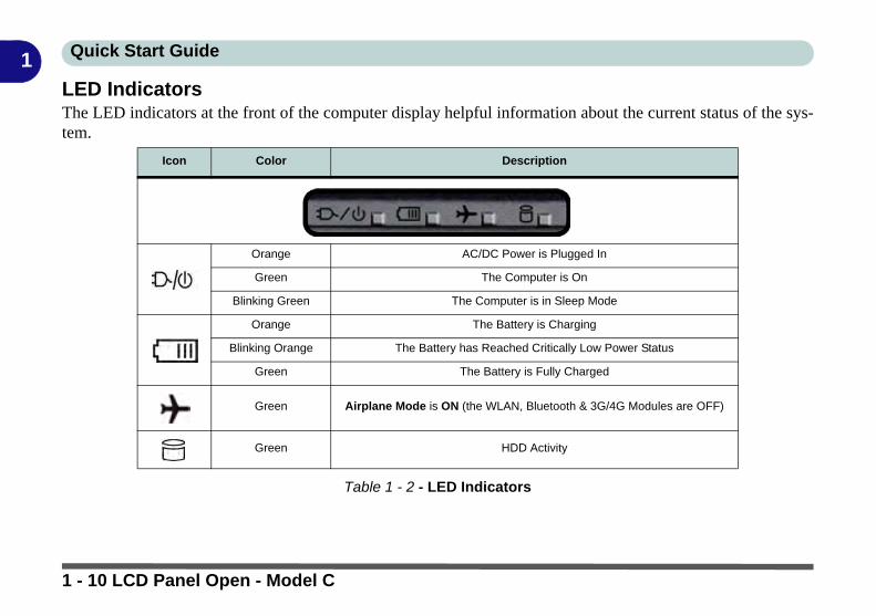
LED IndicatorsThe LED indicators at the front of the computer display helpful information about the current status of the sys-tem.Table 1 - 2 - LED Indicators
Icon Color Description
Orange AC/DC Power is Plugged In
Green The Computer is On
Blinking Green The Computer is in Sleep Mode
Orange The Battery is Charging
Blinking Orange The Battery has Reached Critically Low Power Status
Green The Battery is Fully Charged
Green Airplane Mode is ON (the WLAN, Bluetooth & 3G/4G Modules are OFF)
Green HDD Activity
1 - 10 LCD Panel Open - Model C

Quick Start Guide 1
Illuminated White LED KeyboardThe illuminated white LED keyboard has an embedded numerical keypad for easynumeric data input, and features function keys to allow you to change operationalfeatures instantly. See Table 1 - 6, on page 1 - 24 for full function key combinationdetails.
Figure 1 - 5 - Illuminated White LED Keyboard
Other Keyboards
If your keyboard is dam-aged or you just want tomake a change, you canuse any standard USBkeyboard. The system willdetect and enable it auto-matically. However spe-cial functions/hot-keysunique to the system’sregular keyboard may notwork.
Scr Lk
Hold down the Fn Keyand Scr Lk to enablescroll lock and check theLED indicator for status.
Numerical
Play/Pause Key
Function Keys
ScrLk & NumLk Keys
Fn KeyKeypad
Windows Logo Key Menu/Application Key
Special Characters
Some software applications allow the number-keys to be used with Alt to produce special characters.These special characters can only be produced by using the numeric keypad. Regular number keys (inthe upper row of the keyboard) will not work. Make sure that NumLk is on.
Illuminated White LED Keyboard 1 - 11

Quick Start Guide1
Illuminated Color LED KeyboardThe illuminated colored keyboard has an embedded numerical keypad for easy nu-meric data input, and features function keys to allow you to change operational fea-tures instantly. See Table 1 - 6, on page 1 - 24 for full function key combinationdetails. and see “Keyboard Backlight LED” on page 1 - 15.
Figure 1 - 6 - Illuminated Color LED Keyboard
Other Keyboards
If your keyboard is dam-aged or you just want tomake a change, you canuse any standard USBkeyboard. The system willdetect and enable it auto-matically. However spe-cial functions/hot-keysunique to the system’sregular keyboard may notwork.
Scr Lk
Hold down the Fn Keyand Scr Lk to enablescroll lock and check theLED indicator for status.
Numerical
Play/Pause Key
Function Keys
Scr Lk Key
Fn Key
Game Control Keys
Num Lk Key
Windows Logo Key
Menu/Application Key
Numerical Keypad
Special Characters
Some software applications allow the number-keys to be used with Alt to produce special characters.These special characters can only be produced by using the numeric keypad. Regular number keys (inthe upper row of the keyboard) will not work. Make sure that NumLk is on.
1 - 12 Illuminated Color LED Keyboard

Quick Start Guide 1
Keyboard Application Settings(Illuminated Keyboard Option)If your computer includes an illuminated keyboard (factory option), you will need to install the keyboard Con-trol Center application driver and you can then select the type of keyboard as appropriate for your model’s con-figuration (you can only select keyboards supported by your system). After the driver has been installed, and thesystem restarts, the control panel below will pop-up to allow you to select the illuminated white keyboard foryour system. Click Save to retain the setting chosen.
Figure 1 - 7 - Keyboard Settings for Illuminated Keyboard Option
Keyboard Application Settings 1 - 13

Quick Start Guide1
Control CenterWhen in the Windows Desktop application (not in the Start screen) press the Fn + Esc key combination, ordouble-click the icon in the notification area of the taskbar to toggle the Control Center on/off. The Con-trol Center gives quick access to frequently used controls and enables you to quickly turn the camera/TouchPad on/off (see Appendix B for full details).
Figure 1 - 8 - Control Center
Control Center Access
To run theControl Centerpress the Fn +Esc key com-bination, ordouble-clickthe icon inthe notifica-tion area of thetaskbar.
Close the Control Center by clickingthe close icon in the top right of thepanel (move the cursor onto the topright corner of the panel to highlight it).
1 - 14 Control Center
Quick Start Guide 1
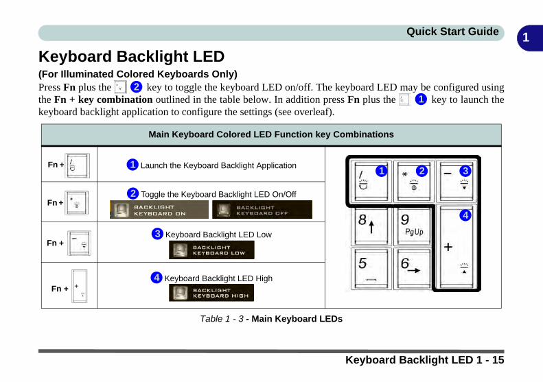
Keyboard Backlight LED(For Illuminated Colored Keyboards Only)Press Fn plus the key to toggle the keyboard LED on/off. The keyboard LED may be configured usingthe Fn + key combination outlined in the table below. In addition press Fn plus the key to launch thekeyboard backlight application to configure the settings (see overleaf).
Table 1 - 3 - Main Keyboard LEDs
Main Keyboard Colored LED Function key Combinations
Fn + Launch the Keyboard Backlight Application
Fn + Toggle the Keyboard Backlight LED On/Off
Fn + Keyboard Backlight LED Low
Fn + Keyboard Backlight LED High
21
12 3
4
1
2
3
4
Keyboard Backlight LED 1 - 15

Quick Start Guide1
Keyboard Backlight Application (for Illuminated Colored Keyboards)The Keyboard Backlight application can be accessed by pressing the Fn plus key (or by clicking theFlexikey button in the Gaming section of the Control Center, and then clicking the Backlight tab).Figure 1 - 9 - Keyboard Backlight Application
Help Butt
Keyboard Sections
Color Swatches
Effects Buttons
1 - 16 Keyboard Backlight LED

Quick Start Guide 1
BrightnessClick on any of the numbers (0 - 3) on the brightness bar to set the brightness level of the keyboard backlight.Color SwatchThe color swatch in the top right of the screen allows you to select a range of colors for your keyboard backlightby clicking on the color required. You can choose to display the swatch either in Full Color or as a 256 ColorScheme. Click the Custom mode button to select any colors from the swatch and to apply your chosen colorsto parts of the keyboard (and Top Case Logo LED if applicable).
Figure 1 - 10 - Keyboard Backlight Color Swatches
Full Color Swatch 256 Color Scheme Swatch
Keyboard Backlight LED 1 - 17

Quick Start Guide1
ModesThe buttons surrounding the swatch allow you to alter the effects of the keyboard backlight. Click on any of thebuttons to view the effects on the keyboard. Click Save when exiting the application to retain the setting.Table 1 - 4 - Mode Buttons
Mode Buttons
Random Color
Wave Up/Down
Custom - Display & Configure Keyboard Sections & Colors
Dancing Effect
Breathe (All Colors)
Tempo Beat
Cycle Colors
Flashing
Illumination Keys
Note that the keyboard illumi-nation (increase/decrease)keys may be used to config-ure the keyboard LED in Cus-tom Mode only.
1 - 18 Keyboard Backlight LED
Quick Start Guide 1
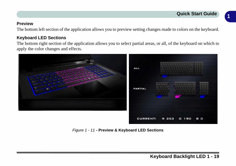
PreviewThe bottom left section of the application allows you to preview setting changes made to colors on the keyboard.Keyboard LED SectionsThe bottom right section of the application allows you to select partial areas, or all, of the keyboard on which toapply the color changes and effects.
Figure 1 - 11 - Preview & Keyboard LED Sections
Keyboard Backlight LED 1 - 19
Quick Start Guide1
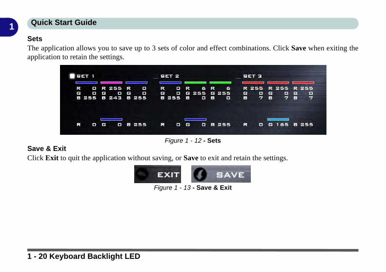
SetsThe application allows you to save up to 3 sets of color and effect combinations. Click Save when exiting theapplication to retain the settings.Figure 1 - 12 - SetsSave & ExitClick Exit to quit the application without saving, or Save to exit and retain the settings.
Figure 1 - 13 - Save & Exit
1 - 20 Keyboard Backlight LED
Quick Start Guide 1
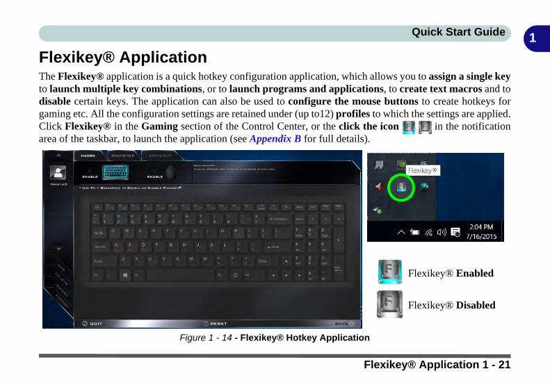
Flexikey® ApplicationThe Flexikey® application is a quick hotkey configuration application, which allows you to assign a single keyto launch multiple key combinations, or to launch programs and applications, to create text macros and todisable certain keys. The application can also be used to configure the mouse buttons to create hotkeys forgaming etc. All the configuration settings are retained under (up to12) profiles to which the settings are applied.Click Flexikey® in the Gaming section of the Control Center, or the click the icon in the notificationarea of the taskbar, to launch the application (see Appendix B for full details).
Figure 1 - 14 - Flexikey® Hotkey Application
Flexikey® Enabled
Flexikey® Disabled
Flexikey® Application 1 - 21
Quick Start Guide1
Flexikey® Application Features:For full details see “Flexikey® Application” on page B - 8.• EXPRESS KEY - This feature allows you to configure a single key (or mouse click) to send multiple key combinations, or to create more useful shortcut keys This is useful in gaming or when using applications which have a complex set of keyboard shortcuts.
• LAUNCH APP - This simply assigns single keys (or mouse clicks) to launch any program’s or applica-tion’s executable file.
• EXPRESS TEXT - With this you can assign single keys (or mouse clicks) to send commonly used strings of text.
• DISABLE - Use this function to disable any keyboard keys or mouse buttons.
• STATISTICS - Use this to quickly record keys in use in any application, and to disable unused keys.
1 - 22 Flexikey® Application
Quick Start Guide 1
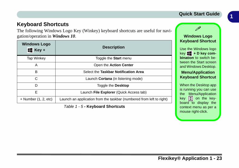
Keyboard ShortcutsThe following Windows Logo Key (Winkey) keyboard shortcuts are useful for navi-gation/operation in Windows 10.Table 1 - 5 - Keyboard Shortcuts
Windows Logo
Key + Description
Tap Winkey Toggle the Start menu
A Open the Action Center
B Select the Taskbar Notification Area
C Launch Cortana (in listening mode)
D Toggle the Desktop
E Launch File Explorer (Quick Access tab)
+ Number (1, 2, etc) Launch an application from the taskbar (numbered from left to right)
Windows Logo
Keyboard Shortcut
Use the Windows logokey + D key com-bination to switch be-tween the Start screenand Windows Desktop.
Menu/Application Keyboard Shortcut
When the Desktop appis running you can usethe Menu/Applicationkey on the key-board to display thecontext menu as per amouse right-click.
Flexikey® Application 1 - 23

Quick Start Guide1
Function Keys & Visual IndicatorsThe function keys (F1 - F12 etc.) will act as hot keys when pressed while the Fn key is held down.Table 1 - 6 - Function Keys & Visual Indicators
Keys Function/Visual Indicators Keys Function/Visual Indicators
Fn +Fan Control Toggle
Automatic / Full Power
Fn + Control Center Toggle (see over)
Fn + Play/Pause (in Audio/Video Programs) Fn + Display Toggle
Fn + Touchpad Toggle Fn + Brightness Decrease/Increase
Fn + Turn LCD Backlight Off
(Press a key to or use Touchpad to turn on)Fn + PC Camera
Power Toggle
Fn + Mute Toggle Fn + Airplane Mode Toggle
Fn + For Backlight
Keyboards Only Toggle Off/High/Low
Fn + Sleep Toggle
Fn + Volume Decrease/Increase
1 - 24 Flexikey® Application

Quick Start Guide 1
Front & Rear Views - All Models Figure 1 - 15Front & Rear Views
All Models
1. LED Power Indica-tors
2. Vent/Fan Intake
Overheating
To prevent your comput-er from overheatingmake sure nothingblocks the vent(s)/fan in-take(s) while the comput-er is in use.
1
2
1
Model A
Model B
2
2 2
Model A
Model B
Model C
Model C
1
2 2
Front & Rear Views - All Models 1 - 25

Quick Start Guide1
Right ViewsFigure 1 - 16Right Views
1. Headphone Jack2. Microphone Jack3. 1 * USB 2.0 Port4. 1 * Type-A USB 3.0
Port (USB 3.1 Gen1)5. Vent/Fan Intake6. Security Lock Slot
(Models A & B Only)
USB Ports
Note that the connec-tions to the USB portsonly fit one way, do notforce them.
1 3 42 5
USB 3.0 (USB 3.1, Gen1) Type A OR C Ports OR USB 2.0 Port
This model includes 3 * USB 3.0 (USB 3.1, Gen1 ports) ports and 1* USB 2.0 port. The USB 2.0 portis the larger black port. The Type-A USB 3.0 (USB 3.1, Gen 1 ports) are the larger blue color ports.The Type-C USB 3.0 (USB 3.1, Gen 1 ports) is the smaller black port. 2 * USB 3.1 (Gen 2) ports areavailable as a factory option (see page A - 4).
6
Model A
Model C
1 3 42 5 6
Model B
1 3 42 5
1 - 26 Right Views

Quick Start Guide 1
Left Views Figure 1 - 17Left Views
1. DC-In Jack2. RJ-45 LAN Jack3. Mini DisplayPort 14. Mini DisplayPort 2 5. HDMI-Out Port6. 1 * Type-C USB 3.0
Port (USB 3.1 Gen1)7. 1 * Type-A USB 3.0
Port (USB 3.1 Gen1)8. Multi-In-1 Card
Reader9. Security Lock Slot
(Model C Only)
HDMI Port
Note that the HDMI Port supportvideo and audio signals to at-tached external displays.
Note that Sound Blaster Cine-ma audio will be disabled whenyou are connecting to an exter-nal display through an HDMIconnection.
526
Multi-in-1 Card Reader
The card reader allows you to use the most popular digital storage card formats:
MMC (MultiMedia Card) / RSMMCSD (Secure Digital) / Mini SD / SDHC / SDXC
USB 3.0 (USB 3.1, Gen1) Type A OR C Ports OR USB 2.0 Port
This model includes 3 * USB 3.0 (USB 3.1, Gen1 ports) ports and 1* USB 2.0 port. The USB 2.0 portis the larger black port. The Type-A USB 3.0 (USB 3.1, Gen 1 ports) are the larger blue color ports.The Type-C USB 3.0 (USB 3.1, Gen 1 ports) is the smaller black port. 2 * USB 3.1 (Gen 2) ports areavailable as a factory option (see page A - 4).
78
Model A
Model B
1 3
52 6 78
1 3
Model C
4
4
52 6 7 81 3 49
Left Views 1 - 27

Quick Start Guide1
Mini Display Ports / HDMI Port
Depending on the port being connected to, external displays can be configured using either the Intel HD Graphics con-trol panel, Project menu (press the Windows logo key on your keyboard and the P key), Display Settings or NVIDIAControl Panel.
Mini Display Port 1 ; If you wish to configure an external display connected to Mini Display Port 1 you must use theIntel HD Graphics control panel menu to configure the display configuration.
Mini Display Port 2 : If you wish to configure an external display connected to Mini Display Port 2 you must use Proj-ect Menu, Display Settings in Windows (see Figure C - 4 on page C - 8) or the NVIDIA Control Panel (see “NVIDIAControl Panel” on page C - 34) to configure the display configuration.
HDMI Port : If you wish to configure an external display connected to the HDMI Port you must use the Intel HD Graph-ics control panel menu to configure the display configuration.
In a multiple display environment, external displays connected to Mini Display Port 2 will be in Extended mode only.
See Appendix C for full information on external display configuration.
Figure 1 - 18 - Left Side View (Mini Display Ports & HDMI Port Highlighted) - Single Model Pictured
1
2
3
2
1 2 3
1 - 28 Left Views

Quick Start Guide 1
3G/4G Module USIM Card Installation (for Models A & B)Follow the instructions below to install the USIM card (which will be supplied byyour service provider) which requires the removal of the battery first.
1. Turn the computer off, and turn it over.2. Slide the latch in the direction of the arrow, and then slide latch in the
direction of the arrow and hold it in place.3. While holding the latch in place, pull the battery up at point in the direction of
the arrow to remove the battery .4. Insert the USIM card (see overleaf).5. Reinsert the battery (see page 1 - 31).
Power Safety
Warning
Before you undertake anyinstallation procedures,make sure that you haveturned off the power, anddisconnected all peripher-als and cables (includingtelephone lines).
Figure 1 - 19Battery Removal &
USIM Card Insertion
1 2
2 34 5
6
123
4
5
6
3G/4G Module USIM Card Installation (for Models A & B) 1 - 29

Quick Start Guide1
3G/4G Module USIM Card InstallationInsert the USIM card as illustrated below (pay careful attention to the orientationof the card as the gold contact side of the card should face downwards) until it clicksfully into position. To eject the card simply press it until it ejects, but do not attemptto eject the card while connected to a 3G/4G network (see below).USIM Card Orientation
Note that the USIMcard’s readable side(with the gold-coloredcontacts) should facedownwards as illustrat-ed.
Figure 1 - 20USIM Card Insertion
1
USIM Card Ejection
Simply press on the USIM card to eject it, however do not do this while a connection is inprogress. If you do eject the card while a 3G/4G connection is ongoing, you will need to shutdown the system, reinsert the USIM card, restart the system and then reestablish the 3G/4Gconnection.
If you wish to change USIM cards then you will need to shut the system down, reinsert theUSIM card, restart the system and then reestablish the 3G/4G connection.
1
1 - 30 3G/4G Module USIM Card Installation (for Models A & B)

Quick Start Guide 1
Battery Insertion1. Orientate the battery as illustrated below and align it with the edges of the bat-tery compartment.2. Push the battery in the direction of the arrow to insert it into the compartment (it
should click into place).3. Slide the latch in the direction of the arrow into the lock position.
Figure 1 - 21Battery Insertion
1
2
3
1
2 3
3G/4G Module USIM Card Installation (for Models A & B) 1 - 31

Quick Start Guide1
Bottom View - Model AFigure 1 - 22Bottom View
Model A
1. Battery2. Fan Outlet/Intake3. Speakers
Bottom Cover Removal
Warning
Do not remove any cover(s)and /or screw(s) for the pur-poses of device upgrade asthis may violate the termsof your warranty.
If you need to replace/re-move the hard disk/RAM/optical device etc., for anyreason, please contact yourdistributor/supplier for fur-ther information.
1
Battery Information
Always completely discharge, then fully charge, a new battery before using it. Completelydischarge and charge the battery at least once every 30 days or after about 20 partial dis-charges.
2
2
3 3
Overheating
To prevent your comput-er from overheatingmake sure nothingblocks the vent(s)/fan in-take(s) while the com-puter is in use.
1 - 32 Bottom View - Model A

Quick Start Guide 1
Bottom View - Model B Figure 1 - 23Bottom View
Model B
1. Battery2. Fan Outlet/Intake3. Speakers
Bottom Cover Removal
Warning
Do not remove any cover(s)and /or screw(s) for the pur-poses of device upgrade asthis may violate the termsof your warranty.
If you need to replace/re-move the hard disk/RAM/optical device etc., for anyreason, please contact yourdistributor/supplier for fur-ther information.
1
Battery Information
Always completely discharge, then fully charge, a new battery before using it. Completelydischarge and charge the battery at least once every 30 days or after about 20 partial dis-charges.
2
2
3 3
Overheating
To prevent your comput-er from overheatingmake sure nothingblocks the vent(s)/fan in-take(s) while the com-puter is in use.
Bottom View - Model B 1 - 33

Quick Start Guide1
Bottom View - Model CFigure 1 - 24Bottom View
Model C
1. Battery2. Fan Outlet/Intake3. Speakers
Battery Removal
Note that the built-inbattery is not user re-movable. Removing thebattery will violate theterms of your warranty.
If you need to remove thebattery for any reason,please contact your dis-tributor/supplier for fur-ther information.
1
Battery Information
Always completely discharge, then fully charge, a new batterybefore using it. Completely discharge and charge the batteryat least once every 30 days or after about 20 partial discharg-es.
Overheating
To prevent your comput-er from overheatingmake sure nothingblocks the vent(s)/fan in-take(s) while the com-puter is in use.
Bottom Cover Removal Warning
Do not remove any cov-er(s) and /or screw(s) forthe purposes of deviceupgrade as this may vio-late the terms of yourwarranty.
If you need to replace/re-move the hard disk/RAM/optical device etc.,for any reason, pleasecontact your distributor/supplier for further infor-mation.
3
2
3
2
1 - 34 Bottom View - Model C

Quick Start Guide 1
Windows 10 Start MenuMost of the apps, control panels, utilities and programs within Windows 10 can be accessed from the StartMenu by clicking the icon in the taskbar in the lower left corner of the screen (or by pressing the WindowsLogo Key on the keyboard).
Figure 1 - 25 - Windows Start Menu
Desktop
Windows 10 Start Menu 1 - 35

Quick Start Guide1
Right-Clicking the Windows Logo In Start MenuRight-click the Start Menu icon (or use the Windows Logo Key + X key combination) to bring up anadvanced Context Menu of useful features such as Control Panel, Programs and Features, Power Options, TaskManager, Search, File Explorer, Command Prompt, Device Manager and Network Connections etc.Figure 1 - 26 - Right-Click Windows Logo in Start Menu
Right-Click Icon
1 - 36 Windows 10 Start Menu

Quick Start Guide 1
Start Menu Apps & TilesThe Windows 10 Start Menu will contain a number of apps, and many more will be installed as you add moreapplications etc. Not all of these apps can fit on the screen so may need click and drag the handles at the edge ofthe screen to expand the menu in order to view all the apps (you can use the scroll bar to move up and down thescreen).Figure 1 - 27 - Expanding the Start Menu
Windows 10 Start Menu 1 - 37

Quick Start Guide1
Pining/Unpinning Apps & Programs to/from the Start MenuTo make things easy to find you can add and remove tiles for apps and programs to the Start Menu. Right-Clickon a program’s icon and select Pin to Start from the drop-down menu. To remove an app or program from theStart Menu right-click the icon and select Unpin from Start. You can use the same method to pin apps/pro-grams to/from the taskbar (select pin to taskbar/unpin this program from the taskbar).Figure 1 - 28 - Pin to Start/Unpin from Start
1 - 38 Windows 10 Start Menu

Quick Start Guide 1
Windows 10 Control PanelIn many instances throughout this manual you will see an instruction to open the Control Panel. The ControlPanel can be accessed in a number of ways in Windows 10.
Figure 1 - 29 - Windows 10 Control Panel Access
• Right-click the Start Menu icon in the taskbar in the lower left
corner of the screen and select Control Panel from the menu.
• Press the Windows logo key on your keyboard and X to bring up the context menu, and then press P to bring up the Control Panel.
• Type Control Panel into the Search box in the taskbar and click on the icon when it pops up.
Windows 10 Control Panel 1 - 39

Quick Start Guide1
SettingsThe Settings item in the Start Menu (and also as an App) gives you quick access to a number of system settingscontrol panels allowing you to adjust settings for System, Devices, Network & internet, Personalization, Ac-counts, Time & language, Ease of Access, Privacy and Update & security.Figure 1 - 30 - Settings
1 - 40 Windows 10 Control Panel

Quick Start Guide 1
Windows 10 TaskbarIn many instances throughout this manual you will see an instruction to access the notification area of the task-bar. The notification area of the taskbar in the bottom right of the screen. Some of the Control Panels and appli-cations referred to throughout the course of this manual can be accessed from here.Figure 1 - 31 - Taskbar
You can pin/unpin apps to/from the taskbar in much the same way as you can to the Start screen (see “Pining/Unpinning Apps & Programs to/from the Start Menu” on page 1 - 38).
Taskbar
Taskbar - Pinned Programs and Apps Notification Area
Windows 10 Control Panel 1 - 41

Quick Start Guide1
Video FeaturesYou can switch display devices, and configure display options, from the Display Settings control panel. In Win-dows 10 it is possible to quickly configure external displays from the Project menu (press the Windows logokey on your keyboard and the P key).
Microsoft Hybrid GraphicsYour computer will feature Microsoft Hybrid Graphics switchable graphics technology. This seamless tech-nology is designed to get best performance from the graphics system while allowing longer battery life, withouthaving to manually change settings. The computer’s operating system (and some applications) will automati-cally switch between the integrated UMA (Unified Memory Architecture) GPU (iGPU) and the discrete GPU(dGPU) when required by the applications in use. This switch is seamless to the user.
The basic video features for this computer can be configured using the Intel® HD Graphics Control Panel.Further video configuration is available through the NVIDA control panel (see the information on the followingpages and Appendix C).
1 - 42 Video Features

Quick Start Guide 1
To Configure Displays using ProjectFigure 1 - 32 - Project (Devices)
1. Attach your display to the appropriate port, and turn it on.2. Press the + P key combination.3. Click on any one of the options from the menu to select PC screen only,
Duplicate, Extend or Second screen only.4. You can also click Connect to a wireless display at the bottom of the
Project screen and follow the steps to connect to any wireless enableddisplay.
Intel or NVIDIA Video Driver Controls
More detailed video controls are provided by the Intel/NVIDIA Control Panel(for more detailed information see Appendix C).
You can also access the control panel by right-clicking the desktop and select-ing Intel(R) Graphics Properties/NVIDIA Control Panel.
Video Features 1 - 43

Quick Start Guide1
To access the Display Settings:1. You can quickly adjust the display by right-clicking the desktop and selecting Display Settings (Figure 1 -33).2. Adjust the settings using the sliders in the menu or click Advanced display settings (Figure 1 - 33) to
change resolution.3. Click Apply to save any changes made to resolution.
Figure 1 - 33 - Display Settings
1
2
2
1
1 - 44 Video Features

Quick Start Guide 1
To access the Intel(R) HD Graphics Control Panel:1. Right-click the desktop and select Intel(R) Graphics Settings from the menu.OR2. Click the icon in the notification area of the Desktop taskbar and select Intel(R) Graphics Settings from themenu.
Figure 1 - 34 - Intel® HD Graphics Control Panel
Video Features 1 - 45

Quick Start Guide1
To access the NVIDIA Control Panel:1. Right-click the desktop and select NVIDIA Control Panel (Figure 1 - 35).OR2. Double-click the icon (Figure 1 - 35) in the Windows control panel.Figure 1 - 35 - NVIDIA Control Panel
1
2
1
2
1 - 46 Video Features

Quick Start Guide 1
Power OptionsPower Options (Hardware and Sound) can be accessed from the Control Panel. The Power button item inStart Menu (or the context menu) may be used to Shut down or Restart (you can also add Hibernate/Sleep tothe menu - see page 1 - 48). To fully control all the power options (including Hibernate mode) go to the PowerOptions control panel and configure the power button, sleep button and lid to perform the function selected.
Figure 1 - 36 - Shut Down/Restart
Using the Power Button1. Go to the Start Menu.2. Click the Power button .3. Select the power state required
from the menu.
Power Options 1 - 47

Quick Start Guide1
You can also use the context menu (right-click the Start Menu icon or press the Windows logo + X keycombination) to Sign out, Sleep, Hibernate, Shut down, and Restart.Figure 1 - 37 - Context Menu Shut Down or sign out
Ctrl + Alt + Delete Key CombinationYou can use the CTRL + ALT + DEL key combination to bring up a full-screen displaying Lock, Sign out,Change a password, Task Manager and Switch User. If you click the Power icon in the lower right corner ofthe screen a power management option menu appears to display Sleep, Hibernate, Shut down, and Restart.
Adding Hibernate/Sleep to the Power Men
1. Go to the Power Options (Hardware and Sound) control panel.
2. Click Choose what the power buttons do.3. Click “Change settings that are currently
unavailable” .4. Click to put a check in the Hibernate/Sleep box
under Shutdown settings.5. Click Save Changes and close the control panel.
1 - 48 Power Options

Quick Start Guide 1
Minimum Screen Resolution Settings1. Windows 10 has minimum screen resolution requirements.2. Right-click a blank area of the Desktop and select Screen Resolution (or go to the Display control panel).3. Adjust the Resolution to make sure that it is at least 1024 * 768, although preferably 1366 * 768 or above.Figure 1 - 38 - Screen Resolution
Power Options 1 - 49

Quick Start Guide1
1 - 50

Storage Devices, Mouse, & Audio
2
Chapter 2: Storage Devices, Mouse, & AudioOverviewRead this chapter to learn more about the following main features and componentsof the computer:
• Hard Disk Drive/Solid State Drive• Multi-in-1 Card Reader• Audio Features• Touchpad and Buttons/Mouse
Overview 2 - 1

Storage Devices, Mouse, & Audio
2
Hard Disk Drive/Solid State DriveThe hard disk drive (HDD) and/or solid state drive (SSD) is used to store your datain the computer. The hard disk can be taken out to accommodate other serial (SATA)hard disk drives (see “Storage” on page D - 2 for specification information), how-ever you will need to contact your distributor/supplier to do this in order to avoidviolating the terms of your warranty.Bottom Cover
Removal Warning
Do not remove any cov-er(s) and /or screw(s) forthe purposes of deviceupgrade as this may vio-late the terms of yourwarranty.
If you need to replace/remove the hard disk forany reason, please con-tact your distributor/sup-plier for furtherinformation.
2 - 2 Hard Disk Drive/Solid State Drive

Storage Devices, Mouse, & Audio
2
Multi-in-1 Card ReaderThe card reader allows you to use some of the latest digital storage cards. Push thecard into the slot and it will appear as a removable device, and can be accessed inthe same way as your hard disk (s). Make sure you install the Card Reader driver(see “Card Reader” on page 4 - 7).Note: Some of these cards require PC adapters that are usually supplied with thecards.
Push-Push Card
Reader
The card reader fea-tures a push-in/push-outcard insertion and ejec-tion mechanism. Simplypush the card to insertand eject it, however MsDuo cards require anadapter.
Figure 2 - 1Left View
1. Card Reader
• MMC (MultiMedia Card) / RSMMC• SD (Secure Digital) / Mini SD / SDHC / SDXC
Model A
Model B
1
1
Model C1
Multi-in-1 Card Reader 2 - 3
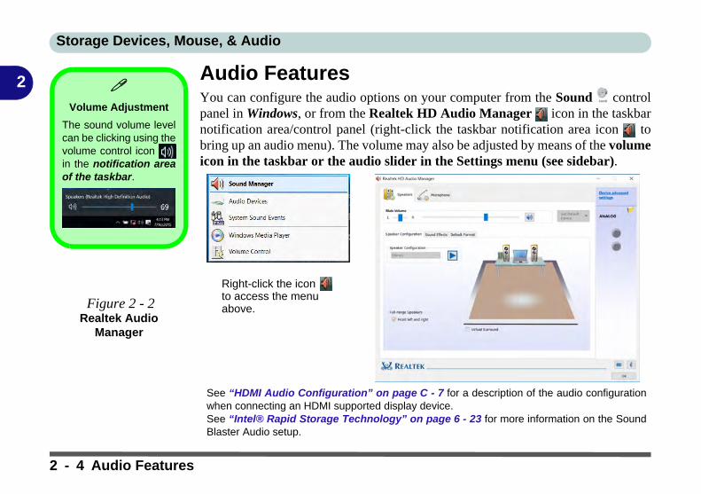
Storage Devices, Mouse, & Audio
2
Audio FeaturesYou can configure the audio options on your computer from the Sound controlpanel in Windows, or from the Realtek HD Audio Manager icon in the taskbarnotification area/control panel (right-click the taskbar notification area icon tobring up an audio menu). The volume may also be adjusted by means of the volumeicon in the taskbar or the audio slider in the Settings menu (see sidebar).Volume Adjustment
The sound volume levelcan be clicking using thevolume control icon in the notification areaof the taskbar.
Figure 2 - 2Realtek Audio
Manager
Right-click the icon to access the menu above.
See “HDMI Audio Configuration” on page C - 7 for a description of the audio configurationwhen connecting an HDMI supported display device. See “Intel® Rapid Storage Technology” on page 6 - 23 for more information on the SoundBlaster Audio setup.
2 - 4 Audio Features
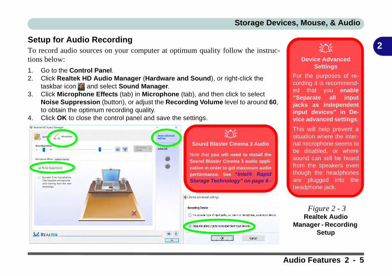
Storage Devices, Mouse, & Audio
2
Setup for Audio RecordingTo record audio sources on your computer at optimum quality follow the instruc-tions below:1. Go to the Control Panel.2. Click Realtek HD Audio Manager (Hardware and Sound), or right-click the
taskbar icon and select Sound Manager.3. Click Microphone Effects (tab) in Microphone (tab), and then click to select
Noise Suppression (button), or adjust the Recording Volume level to around 60, to obtain the optimum recording quality.
4. Click OK to close the control panel and save the settings.
Device Advanced
Settings
For the purposes of re-cording it is recommend-ed that you enable“Separate all inputjacks as independentinput devices” in De-vice advanced settings.
This will help prevent asituation where the inter-nal microphone seems tobe disabled, or wheresound can still be heardfrom the speakers eventhough the headphonesare plugged into theheadphone jack.
Figure 2 - 3Realtek Audio
Manager - Recording Setup
Sound Blaster Cinema 3 Audio
Note that you will need to install the
Sound Blaster Cinema 3 audio appli-
cation in order to get maximum audio
performance. See “Intel® RapidStorage Technology” on page 6 -
Audio Features 2 - 5

Storage Devices, Mouse, & Audio
2
Touchpad and Buttons/MouseThe Touchpad is an alternative to the mouse; however, you can also add a mouse toyour computer through one of the USB ports. The Touchpad buttons function inmuch the same way as a two-button mouse. Make sure you have installed the Touch-pad driver (see “Touchpad” on page 4 - 8).Touchpad SensitivityThe mouse button zones at the bottom of the pad are defined by the line at the bot-tom of the pad, and the left and right buttons are divided roughly down the middle.Press the left button zone for a left click, and right button zone for a right click ac-tion.
Touchpad Cleaning
In order to improve padperformance it is neces-sary to keep the surfaceclean and free of finger-prints and marks etc.
Use a soft dry cleaningcloth to keep the padsurface clean.
Disabling the Pad
Use the Fn + F1 or Con-trol Center button to dis-able the Touchpad.
Mouse Driver
If you are using an externalmouse your operating systemmay be able to auto-configureyour mouse during its installa-tion or only enable its basicfunctions. Be sure to checkthe device’s user documenta-tion for details.
2 - 6 Touchpad and Buttons/Mouse

Storage Devices, Mouse, & Audio
2
Mouse Properties Control PanelYou can configure the functions from the Mouse control panel in Windows as fol-lows.1. Right-click the Start Menu icon.2. Select Control Panel.3. Click Mouse (Hardware and Sound > Devices and Printers).4. Click the menu headings tabs to adjust your mouse preferences.
Disabling the
Touchpad
If you need to disablethe Touchpad for anyreason (e.g. you mayfind that when usingthe computer’s internalkeyboard you acciden-tally trigger the Touch-pad when resting yourwrists or palms on it)you can do so by usingFn + F1 key combina-tion.
Figure 2 - 4Mouse Properties
Control Panel - Buttons
Mouse Properties Control Panel 2 - 7
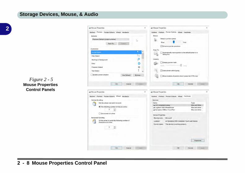
Storage Devices, Mouse, & Audio
2
Figure 2 - 5Mouse Properties
Control Panels
2 - 8 Mouse Properties Control Panel

Storage Devices, Mouse, & Audio
2
Mouse & Touchpad DevicesYou can also configure the functions from the Mouse & touchpad control panel inDevices in the Settings control panel as follows.1. Click the Settings item in the Start Menu (this is also as an App or All Settings in the Action Center).
2. Click Devices.3. Click Mouse & touchpad.
Figure 2 - 6Settings > Mouse &
touchpad
Mouse & Touchpad Devices 2 - 9

Storage Devices, Mouse, & Audio
2
Touchpad SettingsYou can disable the Touchpad by clicking the Touchpad button to turn it off.You can set the system to automatically disable the internal Touchpad when an ex-ternal USB point device (e.g a USB mouse) is attached. Click “Leave touchpad onwhen a mouse is connected” to off.
Figure 2 - 7Mouse & Touchpad (Touchpad turned off
when mouse connected)
2 - 10 Mouse & Touchpad Devices

Storage Devices, Mouse, & Audio
2
Touchapd TapsMake sure “Allow taps on the touchpad” is on if you want to use the tap feature.The Delay feature helps prevent recognizing taps on the pad by accident, by recog-nizing when your palm is resting on it or brushing its surface while you are typing.
Use the drop-down menu to either turn of any delay, or to adjust the delay to yourpreference.
Figure 2 - 8Mouse & Touchpad
Adjust Delay
Mouse & Touchpad Devices 2 - 11

Storage Devices, Mouse, & Audio
2
You to use a specific gesture or taps on the surface of the pad to perform specificactions to manipulate documents, objects and applications, and these may be en-abled or disabled by clicking on the appropriate button.Figure 2 - 9Mouse & TouchpadTaps and Gestures
2 - 12 Mouse & Touchpad Devices

Storage Devices, Mouse, & Audio
2
The two-finger tap acts as a right-click mouse action and can bring up contextmenus etc.The two-finger scrolling feature works in most scrollable windows and allows youto scroll horizontally and vertically. Place two fingers, slightly separated, on theTouchpad surface and slide both fingers in the direction required (in a straight con-tinuous motion).
The two-finger pinch to zoom gesture can be used to perform the same function asa scroll wheel in Windows applications that support CTRL + scroll wheel zoomfunctionality. Place two fingers on the pad (for best results use the tips of the fingers)and slide them apart to zoom in, or closer together to zoom out.
Figure 2 - 10Scrolling Gesture
Figure 2 - 11Zooming Gesture
Mouse & Touchpad Devices 2 - 13

Storage Devices, Mouse, & Audio
2
The three and four-finger taps may be configured may be used to trigger CortanaSearch or the Action Center.The three finger-drags & slides gesture may be used to enhance navigation with avariety of applications such as browsing the Internet or scrolling through a photoviewer.
Figure 2 - 12Mouse & Touchpad
Select Actions
Figure 2 - 13Slide Gesture
2 - 14 Mouse & Touchpad Devices

Storage Devices, Mouse, & Audio
2
The following is an overview of the main gestures you can use with your Touchpad.Figure 2 - 14TouchpadGestures
Mouse & Touchpad Devices 2 - 15

Storage Devices, Mouse, & Audio
2
2 - 16

Power Management
3
Chapter 3: Power Management
OverviewTo conserve power, especially when using the battery, your computer power man-agement conserves power by controlling individual components of the computer(the monitor and hard disk drive) or the whole system. This chapter covers:
• The Power Sources• Turning On the Computer• Power Plans• Power-Saving States• Configuring the Power Buttons• Battery Information
The computer uses enhanced power saving techniques to give the operating system(OS) direct control over the power and thermal states of devices and processors. Forexample, this enables the OS to set devices into low-power states based on user set-tings and information from applications.
OS Note
Power managementfunctions will vary slight-ly depending on youroperating system. Formore information it isbest to refer to the user’smanual of your operat-ing system.
Overview 3 - 1

Power Management
3
The Power SourcesThe computer can be powered by either an AC/DC adapter or a battery pack.
AC/DC AdapterUse only the AC/DC adapter that comes with your computer. The wrong type of AC/DC adapter will damage the computer and its components.
1. Attach the AC/DC adapter to the DC-in jack on the left of the computer.2. Plug the AC power cord into an outlet, and connect the AC power cord to the AC/
DC adapter (make sure you use the adapter when first setting up thecomputer, as to safeguard the computer during shipping, the battery will be lockedto not power the system until first connected to the AC/DC adapter).
3. Raise the lid/LCD to a comfortable viewing angle.4. Press the power button to turn “On”.
BatteryThe battery allows you to use your computer while you are on the road or when anelectrical outlet is unavailable. Battery life varies depending on the applications andthe configuration you're using. To increase battery life, let the battery dischargecompletely before recharging (see “Battery FAQ” on page 3 - 21).
We recommend that you do not remove the battery. For more information on the bat-tery, please refer to “Battery Information” on page 3 - 17.
Forced Off
If the system “hangs”,and the Ctrl + Alt + Delkey combination doesn’twork, press the powerbutton for 4 seconds, orlonger, to force the sys-tem to turn itself off.
3 - 2 The Power Sources

Power Management
3
Turning On the ComputerNow you are ready to begin using your computer. To turn it on simply press the pow-er button on the front panel.
When the computer is on, you can use the power button as a Stand by/Hibernate/Shutdown hot-key button when it is pressed for less than 4 seconds (pressing andholding the power button for longer than this will shut the computer down). UsePower Options (Hardware and Sound) in the Windows control panel to configurethis feature.
Power Button as Stand by or Hibernate Button
You can use the OS’s “Power Options” control panel to set the power button to send thesystem into Stand by or Hibernate mode (see your OS’s documentation, or “Configuringthe Power Buttons” on page 3 - 9 for details).
Turning On the Computer 3 - 3

Power Management
3
Shutting the Computer DownNote that you should always shut your computer down by choosing the Shut downcommand as this will help prevent hard disk or system problems. Use the Power item in the Start Menu and select Shut down.
You can also use the context menu (right-click the Start Menu icon or press theWindows logo + X key combination) to Sign out, Sleep, Hibernate, Shutdown, and Restart.
If you want to add Hibernate/Sleep to the Power Menu see “Adding Hibernate/Sleep to the Power Menu” on page 3 - 10.
Figure 3 - 1Shut Down/Restart
3 - 4 Shutting the Computer Down
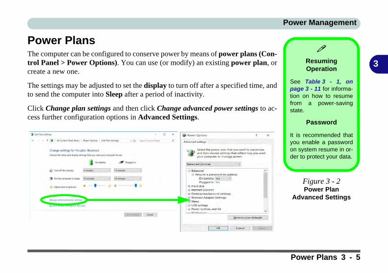
Power Management
3
Power PlansThe computer can be configured to conserve power by means of power plans (Con-trol Panel > Power Options). You can use (or modify) an existing power plan, orcreate a new one.
The settings may be adjusted to set the display to turn off after a specified time, andto send the computer into Sleep after a period of inactivity.
Click Change plan settings and then click Change advanced power settings to ac-cess further configuration options in Advanced Settings.
Resuming Operation
See Table 3 - 1, onpage 3 - 11 for informa-tion on how to resumefrom a power-savingstate.
Password
It is recommended thatyou enable a passwordon system resume in or-der to protect your data.
Figure 3 - 2Power Plan
Advanced Settings
Power Plans 3 - 5

Power Management
3
Each Windows power plan will also adjust the processor performance of your ma-chine in order to save power. This is worth bearing in mind if you are experiencingany reduced performance (especially under DC/battery power).
Choose High performance (you may need to click Show additional plans to viewthe High performance plan) for maximum performance when the computer is pow-ered from an AC power source. Choose the Power saver (bear in mind that thisscheme may slow down the overall performance of the computer in order to savepower) for maximum power saving when the computer is battery (DC power) pow-ered.
Figure 3 - 3Power Plans
Click to Show/Hide additional power plans
3 - 6 Power Plans

Power Management
3
Power-Saving StatesYou can use power-saving states to stop the computer’s operation and restart whereyou left off. Windows 10 uses the Sleep, Hibernate and Shut Down power-savingstates.
SleepIn Sleep all of your work, settings and preferences are saved to memory before thesystem sleeps. When you are not using your computer for a certain length of time,which you specify in the operating system, it will enter Sleep to save power.
The PC wakes from Sleep within seconds and will return you to where you last leftoff (what was on your desktop) without reopening the application(s) and file(s) youlast used.
If your mobile PC in Sleep is running on battery power the system will use only aminimum amount of power. After an extended period the system will save all theinformation to the hard disk and shut the computer down before the battery becomesdepleted.
To add Sleep to the Power Menu see “Adding Hibernate/Sleep to the PowerMenu” on page 3 - 10.
Wake On LAN
Support
Wake-On-LAN is onlysupported from Sleep orHibernate states inWindows.
If you require your com-puter to wake up fromnetwork activity in Win-dows then make surethat the computer is ei-ther in Sleep or Hiber-nate.
Wake-On-LAN is notsupported from Shut-down states in Win-dows.
Power-Saving States 3 - 7

Power Management
3
HibernateHibernate uses the least amount of power of all the power-saving states and savesall of your information on a part of the hard disk before it turns the system off. If apower failure occurs the system can restore your work from the hard disk; if a powerfailure occurs when work is saved only to memory, then the work will be lost. Hi-bernate will also return you to where you last left off within seconds. You shouldput your mobile PC into Hibernate if you will not use the computer for a period oftime, and will not have the chance to charge the battery. To add Hibernate to thePower Menu see “Adding Hibernate/Sleep to the Power Menu” on page 3 - 10.
Shut downYou should Shut down the computer if you plan to install new hardware, plan to beaway from the computer for several days, or you do not need it to wake up and runa scheduled task. Returning to full operation from Shut down takes longer than fromSleep or Hibernate.
Figure 3 - 4Power Button &
Start Menu Power
3 - 8 Power-Saving States

Power Management
3
Configuring the Power ButtonsThe power/sleep button (Fn + F12 key combo) and closed lid may be set to send thecomputer in to a power-saving state. Click Choose what the power buttons do onthe left menu in Power Options to bring up the menu.
Password Protection
It is recommended thatyou enable a passwordon wake up in order toprotect your data.
However you can dis-able this setting from thePower Options menuby clicking Require apassword on wakeupin the left menu, and se-lecting the options (clickChange settings thatare currently unavail-able).
Figure 3 - 5Power Options Define Power
Buttons
Configuring the Power Buttons 3 - 9

Power Management
3
Adding Hibernate/Sleep to the Power MenuAdd Hibernate/Sleep to the Power Menu as follows.
1. Go to the Power Options (Hardware and Sound) control panel.2. Click “Change settings that are currently unavailable” .3. Click Choose what the power buttons do.4. Click to put a check in the Hibernate/Sleep box under Shutdown settings.5. Click Save Changes and close the control panel.
Figure 3 - 6Power Options Define Power
Buttons - Shutdown Settings
3 - 10 Configuring the Power Buttons
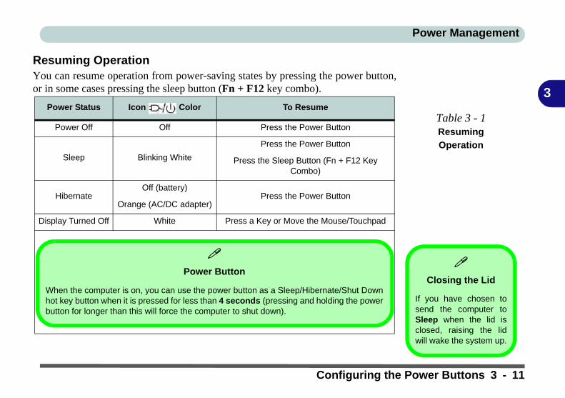
Power Management
3
Resuming OperationYou can resume operation from power-saving states by pressing the power button,or in some cases pressing the sleep button (Fn + F12 key combo).
Power Status Icon Color To Resume
Power Off Off Press the Power Button
Sleep Blinking White
Press the Power Button
Press the Sleep Button (Fn + F12 Key Combo)
HibernateOff (battery)
Press the Power ButtonOrange (AC/DC adapter)
Display Turned Off White Press a Key or Move the Mouse/Touchpad
Table 3 - 1Resuming
Operation
Closing the Lid
If you have chosen tosend the computer toSleep when the lid isclosed, raising the lidwill wake the system up.
Power Button
When the computer is on, you can use the power button as a Sleep/Hibernate/Shut Downhot key button when it is pressed for less than 4 seconds (pressing and holding the powerbutton for longer than this will force the computer to shut down).
Configuring the Power Buttons 3 - 11

Power Management
3
Power Conservation ModesThis system supports Power Saving power management features that place comput-ers (CPU, hard drive, etc.) into a low-power sleep modes after a designated periodof inactivity. Adjust Power Conservation Modes from the Control Center:
1. Press the Fn + Esc key combination to toggle the Control Center on/off.2. Click either the Performance, Balanced or Power Saving button.
Power Conservation
Modes
The Power Saving set-ting will result in maxi-mum power saving, butwith the possible loss ofsome performance.
Setting the mode to Bal-ance will give powersaving matched withperformance.
Performance will giveoptimum computer per-formance but with lesspower conservation.
Note that the EnergyStar setting will put thedisplay into sleep afterno more than 15 min-utes of user inactivity.
Figure 3 - 7Control Center
3 - 12 Configuring the Power Buttons

Power Management
3
Ctrl + Alt + Delete Key CombinationYou can use the CTRL + ALT + DEL key combination from almost any of the Win-dows 10 interfaces/Apps to bring up a full-screen displaying Lock, Switch User,Sign out, Change a password and Task Manager options. If you click the Powericon in the lower right corner of the screen a power management option menu ap-pears to display Sleep, Shut down, and Restart.
To fully control all the power options (including Hibernate mode) go to the PowerOptions control panel and configure the power button, sleep button and lid to per-form the function selected.
Figure 3 - 8Ctrl + Alt + Delete
Menu
Configuring the Power Buttons 3 - 13

Power Management
3
Settings Menu Power ControlsThe Settings item in the Start Menu (and also as an App) gives you access to a num-ber of power settings control panels which enable you to quickly adjust power op-tions. Click System to access the menu including the power option settings.
Figure 3 - 9Settings
3 - 14 Settings Menu Power Controls

Power Management
3
Battery SaverBattery Saver will display the battery level, and by clicking Battery Use you can seethe current state of battery usage by application etc. Click Battery saver settings toadjust the battery saver level.
Figure 3 - 10Settings > Battery
Saver
Settings Menu Power Controls 3 - 15

Power Management
3
Power & SleepPower & sleep gives you quick access to Screen and Sleep settings. Click Addi-tional power settings to go to the main power options control panel.
Figure 3 - 11Settings > Power &
Sleep
3 - 16 Settings Menu Power Controls

Power Management
3
Battery InformationFollow these simple guidelines to get the best use out of your battery.
Battery PowerYour computer’s battery power is dependent upon many factors, including the pro-grams you are running, and peripheral devices attached. You can set actions to betaken (e.g. Shut down, Hibernate etc.), and set critical and low battery levels frompower plan Change plan settings > Change advanced power settings (see Figure3 - 3 on page 3 - 6).
Click the battery icon in the notification area to see the current battery level andcharge status (you can also click Power & sleep settings to access the Settingsmenu to quickly adjust power settings).
Low Battery
Warning
When the battery is criti-cally low, immediatelyconnect the AC/DCadapter to the computeror save your work, oth-erwise, the unsaveddata will be lost whenthe power is depleted.
Figure 3 - 12Battery Icon
(Notification Area) & Battery Advanced
Settings
Battery Information 3 - 17

Power Management
3
Conserving Battery Power• Use a power plan that conserves power (e.g Power saver), however note that
this may have an affect on computer performance.
• Lower the brightness level of the LCD display. The system will decrease LCD brightness slightly to save power when it is not powered by the AC/DC adapter.
• Reduce the amount of time before the display is turned off.
• Close wireless, Bluetooth, modem or communication applications when they are not being used.
• Disconnect/remove any unnecessary external devices e.g. USB devices, ExpressCards etc.
Windows Mobility
Center
The Windows MobilityCenter control panelprovides an easy pointof access for informationon battery status, powerplans used and wirelessdevice status etc.
Figure 3 - 13Windows Mobility
Center (Control Panel)
3 - 18 Battery Information

Power Management
3
Battery LifeBattery life may be shortened through improper maintenance. To optimize the lifeand improve its performance, fully discharge and recharge the battery at leastonce every 30 days.
We should not remove the built-in battery yourself (see sidebar).
New BatteryAlways completely discharge, then fully charge, a new battery (see “Battery FAQ”on page 3 - 21 for instructions on how to do this).
Recharging the Battery with the AC/DC AdapterThe battery pack automatically recharges when the AC/DC adapter is attached andplugged into an electrical outlet. If the computer is powered on, and in use, it willtake several hours to fully recharge the battery. When the computer is turned off butplugged into an electrical outlet, battery charge time is less. Refer to “LCD PanelOpen - Model B” on page 1 - 8 for information on the battery charge status, and to“Battery FAQ” on page 3 - 21 for more information on how to maintain and prop-erly recharge the battery pack.
Battery Removal
Note that the built-inbattery is not user re-movable. Removing thebattery will violate theterms of your warranty.
If you need to removethe battery for any rea-son, please contact yourdistributor/supplier forfurther information.
Battery Information 3 - 19
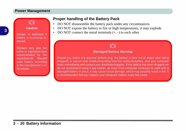
Power Management
3
Proper handling of the Battery Pack• DO NOT disassemble the battery pack under any circumstances• DO NOT expose the battery to fire or high temperatures, it may explode• DO NOT connect the metal terminals (+, -) to each other
Caution
Danger of explosion ifbattery is incorrectly re-placed.
Replace only with thesame or equivalent typerecommended by themanufacturer. Discardused battery accordingto the manufacturer’s in-structions.
Damaged Battery Warning
Should you notice any physical defects (e.g. the battery is bent out of shape after beingdropped), or any unusual smells emanating from the notebook battery, shut your computerdown immediately and contact your distributor/supplier. If the battery has been dropped wedo not recommend using it any further, as even if the computer continues to work with adamaged battery in place, it may cause circuit damage, which may possibly result in fire. Itis recommended that you replace your computer battery every two years.
3 - 20 Battery Information

Power Management
3
Battery FAQHow do I completely discharge the battery?Use the computer with battery power until it shuts down due to a low battery. Don’tturn off the computer even if a message indicates the battery is critically low, just letthe computer use up all of the battery power and shut down on its own.
1. Save and close all files and applications.2. Create a power plan for discharging the battery and set all the options to Never.
Figure 3 - 14Power Plan Create
Battery Information 3 - 21

Power Management
3
3. Click Change plan settings (after creating it) and click Change plan settings > Change advanced power settings.
Figure 3 - 15Change Plan
Settings / Change Advanced Power
Settings
3 - 22 Battery Information

Power Management
3
4. Scroll down to Battery and click + to expand the battery options.5. Choose the options below (click Yes if a warning appears):
• Low battery levels = 0%• Critical battery Levels = 1%• Low battery action = Do Nothing• Critical battery action (On battery) = Shut Down• Critical battery action (Plugged in) = Do Nothing
Figure 3 - 16Power Options
Advanced Settings - Battery
Battery Information 3 - 23
Power Management
3
How do I fully charge the battery?When charging the battery, don’t stop until the LED charging indicator light changesfrom orange to green.
How do I maintain the battery?Completely discharge and charge the battery at least once every 30 days or afterabout 20 partial discharges.
3 - 24 Battery Information

Drivers & Utilities
4
Chapter 4: Drivers & UtilitiesThis chapter deals with installing the drivers and utilities essential to the operation orimprovement of some of the computer’s subsystems. The system takes advantage ofsome newer hardware components for which the latest versions of most available op-erating systems haven’t built in drivers and utilities. Thus, some of the system com-ponents won’t be auto-configured with an appropriate driver or utility duringoperating system installation. Instead, you need to manually install some system-re-quired drivers and utilities.
What to InstallYou will need to attach an external optical CD/DVD device drive to install thedrivers from the Device Drivers & Utilities + User’s Manual disc. The disc con-tains the drivers and utilities necessary for the proper operation of the computer. Ta-ble 4 - 1, on page 4 - 4 lists what you need to install and it is very important thatthe drivers are installed by the method outlined in this chapter, and in the orderindicated. Note that the information on the following pages is for Windows 10 (64-bit) only.
Module Driver InstallationThe procedures for installing drivers for the Wireless LAN, Bluetooth & WLANCombo, Intel Technology, Sound Blaster Cinema and 3G/4G modules are provid-ed in “Modules” on page 6 - 1.
Driver Installation &
Power
When installing driv-ers make sure yourcomputer is poweredby the AC/DC adapterconnected to a work-ing power source.Some drivers draw asignificant amount ofpower during the instal-lation procedure, and ifthe remaining batterycapacity is not adequatethis may cause the sys-tem to shut down andcause system problems(note that there is nosafety issue involvedhere, and the battery willbe rechargeable within 1minute).
What to Install 4 - 1

Drivers & Utilities
4
Driver Installation1. Insert the Device Drivers & Utilities + User’s Manual disc into an attached DVD drive.2. Click the message “Tap to choose what happens with this disc.”3. Click Run autorun.exe.4. Click Install Drivers (button), or Option Drivers (button) to access the Optional driver menu.
Figure 4 - 1 - Drivers Installer Screen 1
4 - 2 Driver Installation

Drivers & Utilities
4
5. Check the driver installation order from Table 4 - 1, on page 4 - 4 (the drivers must be installed in this order) which is the same as that listed in the Drivers Installer menu below.
6. Click to select the driver you wish to install, (you should note down the drivers as you install them).7. Follow the instructions for each individual driver installation procedure as listed on the following pages.
Figure 4 - 2 - Install Drivers
Driver Installation 4 - 3
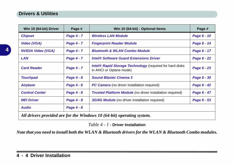
Drivers & Utilities
4
Table 4 - 1 - Driver Installation
Note that you need to install both the WLAN & Bluetooth drivers for the WLAN & Bluetooth Combo modules.
Win 10 (64-bit) Driver Page # Win 10 (64-bit) - Optional Items Page #
Chipset Page 4 - 7 Wireless LAN Module Page 6 - 10
Video (VGA) Page 4 - 7 Fingerprint Reader Module Page 6 - 14
NVIDIA Video (VGA) Page 4 - 7 Bluetooth & WLAN Combo Module Page 6 - 17
LAN Page 4 - 7 Intel® Software Guard Extensions Driver Page 6 - 22
Card Reader Page 4 - 7Intel® Rapid Storage Technology (required for hard disks in AHCI or Optane mode)
Page 6 - 23
Touchpad Page 4 - 8 Sound Blaster Cinema 3 Page 6 - 30
Airplane Page 4 - 8 PC Camera (no driver installation required) Page 6 - 42
Control Center Page 4 - 8 Trusted Platform Module (no driver installation required) Page 6 - 47
MEI Driver Page 4 - 8 3G/4G Module (no driver installation required) Page 6 - 53
Audio Page 4 - 8
All drivers provided are for the Windows 10 (64-bit) operating system.
4 - 4 Driver Installation

Drivers & Utilities
4
Manual Driver InstallationClick Browse CD/DVD (button) in the Drivers Install-er application and browse to the executable file in theappropriate driver folder.
Windows UpdateAfter installing all the drivers make sure you enableCheck for updates (Settings > Update & security >Check for updates) in order to get all the latest secu-rity updates etc. (all updates will include the latest hot-fixes from Microsoft). See “Windows Update” onpage 4 - 9 for instructions.
Updating/Reinstalling Individual DriversIf you wish to update/reinstall individual drivers itmay be necessary to uninstall the original driver.To dothis go to the Control Panel in the Windows OS anddouble-click the Programs icon (Programs > Unin-stall a program). Click to select the driver (if it is notlisted see below) and click Uninstall, and then followthe on screen prompts (it may be necessary to restartthe computer). Reinstall the driver as outlined in thischapter.
If the driver is not listed in the Programs and Fea-tures menu:
1. Go to the Control Panel).2. Double-click Device Manager (Hardware and
Sound > Devices and Printers > Device Manager).
3. Double-click the device you wish to update/reinstall the driver for (you may need to click “+” to expand the selection).
4. Click Driver (tab) and click the Update Driver or Uninstall button and follow the on screen prompts.
Driver Installation 4 - 5
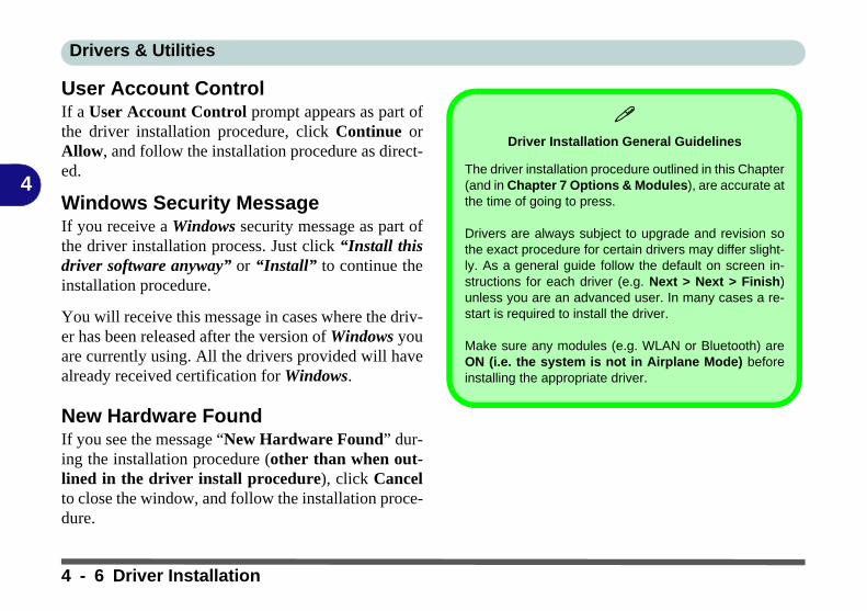
Drivers & Utilities
4
User Account ControlIf a User Account Control prompt appears as part ofthe driver installation procedure, click Continue orAllow, and follow the installation procedure as direct-ed.
Windows Security MessageIf you receive a Windows security message as part ofthe driver installation process. Just click “Install thisdriver software anyway” or “Install” to continue theinstallation procedure.
You will receive this message in cases where the driv-er has been released after the version of Windows youare currently using. All the drivers provided will havealready received certification for Windows.
New Hardware FoundIf you see the message “New Hardware Found” dur-ing the installation procedure (other than when out-lined in the driver install procedure), click Cancelto close the window, and follow the installation proce-dure.
Driver Installation General Guidelines
The driver installation procedure outlined in this Chapter(and in Chapter 7 Options & Modules), are accurate atthe time of going to press.
Drivers are always subject to upgrade and revision sothe exact procedure for certain drivers may differ slight-ly. As a general guide follow the default on screen in-structions for each driver (e.g. Next > Next > Finish)unless you are an advanced user. In many cases a re-start is required to install the driver.
Make sure any modules (e.g. WLAN or Bluetooth) areON (i.e. the system is not in Airplane Mode) beforeinstalling the appropriate driver.
4 - 6 Driver Installation

Drivers & Utilities
4
Driver Installation ProcedureInsert the Device Drivers & Utilities + User’s Manualdisc and click Install Drivers (button).
Chipset1. Click 1.Install Chipset Driver > Yes.2. Click Next > Accept > Install.3. Click Restart Now to restart the computer.
Video (VGA)1. Click 2.Install VGA Driver > Yes.2. Click Next > Yes > Next > Next.3. Click Finish to restart the computer.
NVIDIA Video (VGA)1. Click 3.Install NVIDIA VGA Driver > Yes.2. Click AGREE AND CONTINUE (button) to
accept the terms of the license agreement.3. Click Next.4. Click the Close button to complete the installa-
tion.
5. After all the drivers have been installed (an internet connection is required) run the NVIDIA GeForce Experience by clicking the
desktop icon (or App).
Note: After installing the video driver go to the Dis-play control panel to adjust the video settings to thehighest resolution.
LANNote: If the computer enters a deep sleep mode duringinstallation, you will be prompted to plug in a networkcable, and click OK, to continue installation. If a net-work cable is not available, restart the system and re-install the LAN driver.
1. Click 4.Install LAN Driver > Yes.2. Click Next > Install.3. Click Finish.
Card Reader1. Click 5.Install Cardreader Driver > Yes.2. Click Finish.
Driver Installation 4 - 7

Drivers & Utilities
4
Touchpad1. Click 6.Install Touchpad Driver > Yes.2. Click Next.3. Click the button to accept the license, and then
click Next.4. Click Finish > Restart Now to restart the com-
puter.
AirplaneNote: Do not use Update Driver in Device Manager toinstall the Airplane Mode driver.
1. Click 7.Install Airplane Driver > Yes. 2. Click Next > Install.3. Click Finish to restart the computer.
Control Center1. Click 8.Install Control Center AP > Yes.2. Click Next > Install.3. Click Finish to restart your computer (see
Appendix B).
MEI Driver1. Click 9.Install MEI Driver > Yes.2. Click Next.3. Click the check box to accept the license and
then click Next.4. Click Next.5. Click Finish.
Audio1. Click 10.Install Audio Driver > Yes. 2. Click Next.3. Click Finish to restart the computer.
Note that after installing the audio driver the systemwill not return to the Drivers Installer screen. To in-stall any of the optional drivers listed overleaf, ejectthe Device Drivers & Utilities + User’s Manual discand then reinsert it (or double-click the disc icon in MyComputer), and click Option Drivers (button) to ac-cess the optional driver menu.
(See Overleaf)
4 - 8 Driver Installation
Drivers & Utilities
4
It is recommended that you install the Sound BlasterAudio application (see “Sound Blaster Cinema 3” onpage 6 - 30) and Intel Rapid Storage Technologydriver (see “Intel® Rapid Storage Technology” onpage 6 - 23 - required for AHCI or Optane mode).
Windows Update
After installing all the drivers make sure you enable Win-dows Update in order to get all the latest security up-dates etc (all updates will include the latest hotfixesfrom Microsoft).
To enable Windows Update make sure you are con-nected to the internet:
1. Go to the Control Panel.2. Click Windows Update (System and Security/
Security).3. Click Check for updates (button).4. The computer will now check for updates (you
need to be connected to the internet).5. Click Install now (button) to begin checking for the
updates.6. Click Install updates (button) to install the
updates.
Driver Installation 4 - 9

Drivers & Utilities
4
Optional DriversSee the pages indicated in Table 4 - 1, on page 4 - 4 for the driver installation procedures for any modules in-cluded in your purchase option.
Figure 4 - 3 - Optional Drivers Installer Screen
Note that you need to install both the WLAN & Bluetooth drivers for the WLAN & Bluetooth Combo modules.
Models A & B
4 - 10 Driver Installation
BIOS Utilities
5
Chapter 5: BIOS Utilities
OverviewThis chapter gives a brief introduction to the computer’s built-in software:
Diagnostics: The POST (Power-On Self Test)
Configuration: The Setup utility If your computer has never been set up, or you are making important changes to thesystem (e.g. hard disk setup), then you should review this chapter first and note theoriginal settings found in Setup. Even if you are a beginner, keep a record of the set-tings you find and any changes you make. This information could be useful if yoursystem ever needs servicing.
There is one general rule: Don’t make any changes unless you are sure of what youare doing. Many of the settings are required by the system, and changing them couldcause it to become unstable or worse. If you have any doubts, consult your servicerepresentative.
BIOS Screens
Note that the BIOSscreens pictured onthese pages are intend-ed for guidance in set-ting up your system’sBIOS.
BIOS versions are sub-ject to constant changeand revision, thereforeyour computer’s actualscreens may appearslightly different fromthose pictured on thesepages.
Overview 5 - 1

BIOS Utilities
5
The Power-On Self Test (POST)If you enable the Boot-time Diagnostic Screen in the Setup Utility, each time youturn on the computer the system takes a few seconds to conduct a POST, includinga quick test of the on-board RAM (memory).
As the POST proceeds, the computer will tell you if there is anything wrong. If thereis a problem that prevents the system from booting, it will display a system summaryand prompt you to run Setup.
If there are no problems, the Setup prompt will disappear and the system will loadthe operating system. Once that starts, you can’t get into Setup without rebooting.
BIOS Settings
Warning
Incorrect settings cancause your system tomalfunction. To correctmistakes, return to Set-up and restore the Opti-mized Defaults with<F3>.
UEFI Boot & POST
When UEFI Boot is en-abled, then the promptsto press F2 or F7 willnot appear. Howeveryou can still press F2 toenter the setup, or F7 tochoose the preferredboot device, if you pressthe key immediately thesystem boots up.
5 - 2 The Power-On Self Test (POST)

BIOS Utilities
5
Failing the POSTErrors can be detected during the POST. There are two categories, “fatal” and “non-fatal”.
Fatal ErrorsThese stop the boot process and usually indicate there is something seriously wrongwith your system. Take the computer to your service representative or authorizeddistributor/supplier as soon as possible.
Non-Fatal ErrorsThis kind of error still allows you to boot. You will get a message identifying theproblem (make a note of this message!) and you can then press F7 (the F7 on screenwill be highlighted to illustrate that the system is processing the request) for boot op-tions.
Press F2 (give the system a few seconds to enter Setup; the F2 on screen will behighlighted to illustrate that the system is processing the request) to run the Setupprogram and try to correct the problem. If you still get an error message after youchange the setting, or if the “cure” seems even worse, call for help.
The Power-On Self Test (POST) 5 - 3

BIOS Utilities
5
The Setup UtilityThe Aptio Setup Utility tells the system how to configure itself and manage basicfeatures and subsystems (e.g. port configuration).
Entering SetupTo enter Setup, turn on the computer and press F2 (give the system a few secondsto enter Setup; the F2 on screen will be highlighted to illustrate that the system isprocessing the request) during the POST (or press F7 for boot options). If you get a“Keyboard Error”, (usually because you pressed F2 too quickly) just press F2 again.
If the computer is already on, reboot using the Ctrl + Alt + Delete combination andthen hold down F2 when prompted. The Setup main menu will appear.
To see the boot options press F7.
BIOS Settings
Warning
Incorrect settings cancause your system tomalfunction. To correctmistakes, return to Set-up and restore the Opti-mized Defaults with<F3>.
5 - 4 The Setup Utility

BIOS Utilities
5
Setup ScreensThe following pages contain additional advice on portions of the Setup. Along thetop of the screen is a menu bar with menu headings. When you select a heading, anew screen appears. Scroll through the features listed on each screen to make chang-es to Setup.
Instructions on how to navigate each screen are in the box at the bottom right side ofthe screen.
If these tools are confusing, press F1 to call up a General Help screen, and then usethe arrow keys to scroll up or down the page.
The Item Specific Help on the upper right side of each screen explains the highlight-ed item and has useful messages about its options.
If you see an arrow next to an item, press Enter to go to a sub-menu on that sub-ject. The sub-menu screen that appears has a similar layout, but the Enter key mayexecute a command.
Setup Menus
The Setup menusshown in this section arefor reference only. Yourcomputer’s menus willindicate the configura-tion appropriate for yourmodel and options.
Figure 5 - 1Navigation Menu
The Setup Utility 5 - 5

BIOS Utilities
5
Main Menu
SATA Port # (Main Menu)Pressing Enter opens the sub-menu to show the configuration of a optical Device/HDD on the computer’s SATA Ports.
Figure 5 - 2Main Menu
5 - 6 Main Menu

BIOS Utilities
5
OffBoard SATA/NVme Controller Configuration (Main Menu)Pressing Enter opens the sub-menu to show the configuration of any devices on theoff board SATA/NVme Controller if applicable.
System Time & Date (Main Menu)The hour setting uses the 24-hour system (i.e., ØØ = midnight; 13 = 1 pm). If youcan change the date and time settings in your operating system, you will also changethese settings. Some applications may also alter data files to reflect these changes.
ME FW Version/System/Extended Memory (Main Menu)This item contains information on the system memory, and is not user configurable.The system will auto detect the amount of memory installed.
MB Series/BIOS Revision/KBC/EC firmware Revision/Mac Address (MainMenu)This item contains information on the BIOS version, and the identifier address forthe device on a network, and is not user configurable.
Main Menu 5 - 7

BIOS Utilities
5
Advanced Menu
Advanced Chipset Control (Advanced Menu)The sub-menu here allows you to enable/disable GPU Performance Scaling, Flex-iCharger (see page 5 - 9), SW Guard Extensions and VT-d.
GPU Performance Scaling (Advanced Menu > Advanced Chipset Control)You can enable/disable NVIDIA GPU Performance scaling from this menu. TheNVIDIA Card does the scaling if this option is on, and has less latency than the IntelGPU. This can be useful if you play games etc.
Figure 5 - 3Advanced Menu
5 - 8 Advanced Menu

BIOS Utilities
5
FlexiCharger (Advanced Menu > Advanced Chipset Control)The sub-menu here allows you to enable/disable the FlexiCharger. The FlexiCharg-er may be set to automatically start charging your battery when the battery reachesa certain capacity level (e.g. you could start the battery charge level at 40%).
See the sidebar warning for information on running the FlexiCharger for an ex-tended period as this is not recommended.
Software Guard Extensions (Advanced Menu > Advanced Chipset Control)Intel provides SGX, which is a set of instructions allowing user-level code a degreeof security, and privacy, from the operating system.
VT-d (Advanced Menu > Advanced Chipset Control)Enable/disable Intel® Virtualization Technology for Directed I/O (VT-d) fromthis menu. This extends Intel's Virtualization Technology (VT) by providing hard-ware assists for a virtualization solution.
FlexiCharger
Warning
If you leave the FlexiCh-arger continuously "En-abled” for a period ofthree months or more,the battery meter's read-ing accuracy will deteri-orate.
To reset this, set theFlexiCharger to "Dis-abled", and then allowthe battery to completelydischarge (see “BatteryFAQ” on page 3 - 21)before enabling thefunction again.
Figure 5 - 4Advanced Chipset
Control > FlexiCharger
Advanced Menu 5 - 9

BIOS Utilities
5
SATA Mode (Advanced Menu)The SATA (Serial ATA) control is configured to operate in AHCI (Advanced HostController Interface) mode or in Intel RST Premium (for Intel® Optane™) mode.
The SATA Mode should be set BEFORE installing an operating system, and afteryou have backed up all necessary files and data (see sidebar). See “Setting Up SATAMode (Optane™ or AHCI)” on page 6 - 2 for details. Make sure you install the In-tel Rapid Storage Technology application if you have set the SATA Mode to IntelRST Premium, or to AHCI (see “IRST Driver Installation” on page 6 - 23).
If you wish to change your SATA mode to/from AHCI/Intel RST (Optane) modenote that doing so may prevent your operating system from booting, and may requirea reinstall of the OS. If you do wish to change the SATA mode then backup any nec-essary data on your hard disk(s) as you will need wipe the disks clean in order to pre-vent system problems.
Power On Boot Beep (Advanced Menu)Use this menu item to enable/disable the beep as the computer starts up.
Battery Low Alarm Beep (Advanced Menu)Use this menu item to enable/disable the battery low alarm beep.
Intel® Optane™
Intel® Optane™ is a combi-nation of a compatiblememory device and IntelRapid Technology soft-ware. This combination isdesigned to speed up yoursystem performance.
Contact your distributor orsupplier to see if your sys-tem supports this technolo-gy.
SATA Mode Selection
If you have installed theWindows OS with eitherAHCI or Intel RST (Op-tane) mode enabled, DONOT disable the set mode(if you wish to disable theset mode you will need toreinstall the Windows OS).
5 - 10 Advanced Menu

BIOS Utilities
5
Security Menu
Set Supervisor Password (Security Menu)You can set a password for access to the Aptio Setup Utility. This will not affectaccess to the computer OS (only the Aptio Setup Utility).
Security Menu
The changes you makehere affect the accessto the Setup utility itself,and also access to yourmachine as it boots upafter you turn it on.These settings do notaffect your machine ornetwork passwordswhich will be set in yoursoftware OS.
Figure 5 - 5Security Menu
Security Menu 5 - 11

BIOS Utilities
5
Note: To clear existing passwords press Enter and type the existing password, thenpress Enter for the new password (without typing any password entry) and Enteragain to confirm the password clearance.
Note: You can only set the user password after you have set the supervisor pass-word.
Set User Password (Security Menu)You can set a password for user mode access to the Aptio Setup Utility. This willnot affect access to the computer OS, (only the Setup utility) unless you choose toset a Password on Boot (see below). Many menu items in the Aptio Setup Utilitycannot be modified in user mode.
Note: You can only set the user password after you have set the supervisor pass-word.
Password on boot: (Security Menu)Specify whether or not a password should be entered to boot the computer (you mayonly set a password on boot if a supervisor password is enabled). If “Enabled”is selected, only users who enter a correct password can boot the system (see thewarning in the sidebar). The default setting is “Disabled”.
Password Warning
If you set a boot pass-word (Password on bootis “Enabled“), NEVERforget your password.
The consequences ofthis could be serious. Ifyou cannot rememberyour boot password youmust contact your ven-dor and you may lose allof the information onyour hard disk.
5 - 12 Security Menu

BIOS Utilities
5
Secure Boot Control (Security Menu)Secure Boot Control prevents unauthorized operating systems and software fromloading during the startup process. Secure Boot is available as a menu option if youhave enabled UEFI Boot (see “Boot Menu” on page 5 - 15). Enabling Secure Bootwill bring up the Secure Boot Mode menu to enable you to configure Secure Bootas Standard (with a fixed secure boot policy), or Custom (which enables you tomake changes to the Key Management database).
Figure 5 - 6Security -
Secure Boot(Key Management)
Security Menu 5 - 13

BIOS Utilities
5
TPM Configuration (Security Menu)This sub-menu will allow you to enable/disable Trusted Platform Module (TPM)support, and to configure the TPM State. Select TPM Configuration and press En-ter to access the sub-menu. Press Enter to access the Security Device Support menuand select Enable to support TPM. You can select Pending operation, and then se-lect TPM clear to clear existing TPM information in order to reset the TPM (see“Trusted Platform Module” on page 6 - 47 for details).
Figure 5 - 7Security Device
Support
5 - 14 Security Menu

BIOS Utilities
5
Boot Menu
When you turn the computer on it will look for an operating system (e.g. Windows7) from the devices listed in this menu, and in this priority order. If it cannot findthe operating system on that device, it will try to load it from the next device in theorder specified in the Boot Option Priorities.
Figure 5 - 8Boot Menu
BIOS Screens
Note that the BIOSscreens pictured onthese pages are intend-ed for guidance in set-ting up your system’sBIOS.
BIOS versions are sub-ject to constant changeand revision, thereforeyour computer’s actualscreens may appearslightly different fromthose pictured on thesepages.
Boot Menu 5 - 15

BIOS Utilities
5
Boot Option Priorities (Boot Menu)Press Enter to select the Boot Option # and use the arrow keys to select any devicein order to move its boot priority up and down the list (the selected device will behighlighted in white).
UEFI Boot (Boot Menu)Enable/disable UEFI Boot from this menu. The Unified Extensible Firmware Inter-face (UEFI) specification provides a clean interface between operating systems andplatform firmware at boot time. In contrast to BIOS, UEFI defines a set of standardboot and runtime services. The Network Stack item will be enabled as an option un-der UEFI Boot.
UEFI Boot is enabled for your system by default. It is recommended that youkeep UEFI Boot enabled for the Windows operating system.
5 - 16 Boot Menu
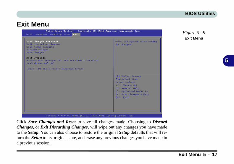
BIOS Utilities
5
Exit Menu
Click Save Changes and Reset to save all changes made. Choosing to DiscardChanges, or Exit Discarding Changes, will wipe out any changes you have madeto the Setup. You can also choose to restore the original Setup defaults that will re-turn the Setup to its original state, and erase any previous changes you have made ina previous session.
Figure 5 - 9Exit Menu
Exit Menu 5 - 17

BIOS Utilities
5
5 - 18

Modules
6
Chapter 6: Modules
OverviewThis chapter contains the information on the various modules (some of which areoptional) which may come with your computer, depending on the configurationpurchased. If you are unsure please contact your service representative.
The chapter includes information on the following:
• Setting Up SATA Mode (Optane™ or AHCI)• Wireless LAN Module• Fingerprint Reader Module• Bluetooth & WLAN Combo Module• Intel® Software Guard Extensions Driver• Intel® Rapid Storage Technology• Sound Blaster Cinema 3• PC Camera• Trusted Platform Module• 3G/4G Module
Overview 6 - 1

Modules
6
Setting Up SATA Mode (Optane™ or AHCI)AHCI ModeAdvanced Host Controller Interface (AHCI) is an interface specification that allowsthe storage driver to enable advanced serial ATA features such as Native CommandQueuing (for maximum hard disk efficiency and performance). Make sure you in-stall the Intel® Rapid Storage Technology application to support your HDDs/SSDs in AHCI mode (see “Intel® Rapid Storage Technology” on page 6 - 23).
Intel® Optane™Intel® Optane™ is a combination of a compatible memory device and Intel RapidTechnology software. This combination is designed to speed up your system per-formance by caching boot data, executables, frequently accessed data and systempage files to an non volatile, low latency Intel® Optane™ SSD.
Contact your distributor or supplier to see if your system supports this technology.
Intel® Rapid Storage Technology ApplicationMake sure you install the Intel® Rapid Storage Technology application if youhave set up your system in Intel RST Premium (for Intel® Optane™) mode (see“Intel® Rapid Storage Technology” on page 6 - 23).
After setting the SATA mode to Intel® Optane™ and installing the Intel® RapidStorage Technology application, DO NOT uninstall the Intel® Rapid StorageTechnology application.
SATA Mode Selection
The SATA mode selec-tion should be made be-fore installing youroperating system.
DO NOT change yourselected SATA modeunless you intend to re-install your operatingsystem. Make sure youhave backed up all yourdata before doing so.
See “SATA Mode (Ad-vanced Menu)” onpage 5 - 10.
6 - 2 Setting Up SATA Mode (Optane™ or AHCI)
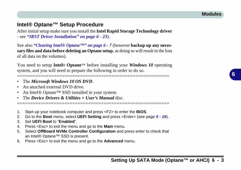
Modules
6
Intel® Optane™ Setup ProcedureAfter initial setup make sure you install the Intel Rapid Storage Technology driver- see “IRST Driver Installation” on page 6 - 23).
See also “Clearing Intel® Optane™” on page 6 - 7 (however backup up any neces-sary files and data before deleting an Optane setup, as doing so will result in the lossof all data on the volumes).
You need to setup Intel® Optane™ before installing your Windows 10 operatingsystem, and you will need to prepare the following in order to do so.==========================================================• The Microsoft Windows 10 OS DVD.• An attached external DVD drive.• An Intel® Optane™ SSD installed in your system.• The Device Drivers & Utilities + User’s Manual disc.==========================================================
1. Start-up your notebook computer and press <F2> to enter the BIOS.2. Go to the Boot menu, select UEFI Setting and press <Enter> (see page 5 - 16).3. Set UEFI Boot to “Enabled”.4. Press <Esc> to exit the menu and go to the Main menu.5. Select OffBoard NVMe Controller Configuration and press enter to check that
an Intel® Optane™ SSD is present.6. Press <Esc> to exit the menu and go to the Advanced menu.
Setting Up SATA Mode (Optane™ or AHCI) 6 - 3

Modules
6
7. Select SATA Mode (see page 5 - 11), press <Enter> and select “Intel RST Premium”.
8. Press <F4> and <Yes> to “Save Changes and Reset”.9. As the computer restarts press <F2> to enter the BIOS again.10. Go to Intel(R) Rapid Storage Technology (Advanced menu) and press <Enter>.11. . (Note this item only appears after you have restarted and accessed the BIOS
again after having set SATA Mode to Intel RST Premium.)
12. If you are reinstalling a system that has previously been setup in Intel RST Premium mode, make sure you have cleared the Intel Optane Memory (see “Clearing Intel® Optane™” on page 6 - 7).
Figure 6 - 1SATA Mode
Selection (BIOS)
Figure 6 - 2Intel(R) Rapid
Storage Technology (Advanced Menu)
6 - 4 Setting Up SATA Mode (Optane™ or AHCI)

Modules
6
13. Press <F4> and <Yes> to “Save Changes and Reset”, however ensure that the condition in the bulleted point below is met before doing so.
• Make sure the Windows 10 OS DVD is in the attached DVD drive, as the com-puter starts up it will automatically boot from the Windows 10 OS DVD (you will be prompted to press a key to boot from the DVD).
14. Press <F7> as the computer starts up to bring up the boot device menu.15. Select the DVD drive containing the Windows 10 OS DVD and press <Enter>.16. Press a key at system startup to begin installing Windows from your Microsoft
Windows 10 disc. 17. Click Next > Install Now to continue installing the operating system as normal
(see your Windows documentation if you need help on installing the Windows OS).
18. Select Custom: Install Windows only (advanced).19. It is recommended that you select and then delete existing partitions.20. Click New to create a partition for Windows.21. It is very important to make sure that when you create the partition, to leave at
least a minimum of unallocated space of 5MB (see sidebar).22. Follow the on-screen instructions to install the Windows 10 operating system.23. Install the Windows drivers from the Device Drivers & Utilities + User’s Manual
disc as per Table 4 - 1, on page 4 - 4 (make sure you install the Intel Rapid Storage Technology driver - see overleaf).
24. Run the Intel® Rapid Storage Technology application to manage your Intel® Optane™ system as instructed in “Intel® Rapid Storage Technology for Optane Systems” on page 6 - 24.
Creating a Windows Partition for Optane
When installing Win-dows, make sure thatyou leave a minimum of5MB of unallocatedspace for the Intel® Op-tane™ software to cre-ate needed metadata.
After you have created aWindows partition theWindows Setup screenwill display the partitionsand sizes, including theunallocated space. If theunallocated space isless than 5MB, then de-lete the partitions andrecreate them until thecriteria is met.
Note this is 5MB only,not GB.
Setting Up SATA Mode (Optane™ or AHCI) 6 - 5

Modules
6
25. After installing the Intel® Rapid Storage Technology application you can access Device Manager (right-click the Start menu and select Device Manager).
26. Click Disk drives to check the Optane drive.
Figure 6 - 3 Device Manager
(Disk drives)
6 - 6 Setting Up SATA Mode (Optane™ or AHCI)

Modules
6
Clearing Intel® Optane™If you wish to clear an existing Intel® Optane™ setup then follow the procedure be-low to do so. However backup up any necessary files and data before clearing anIntel® Optane™ setup, as doing so will result in the loss of all data on the volumes.
1. Make sure that Intel® Optane™ is Enabled in the Intel® Rapid Storage Tech-nology application.
2. Start-up your computer and press <F2> to enter the BIOS.3. Go to Intel(R) Rapid Storage Technology (in the Advanced menu) and press
<Enter>.4. Select Intel Optane, **** (listed under Optane Volume:) and press <Enter>.
Figure 6 - 4Intel(R) Rapid
Storage Technology (Advanced Menu)
Setting Up SATA Mode (Optane™ or AHCI) 6 - 7

Modules
6
5. Select “Deconcatentate” and press <Enter>.
6. Select Yes from the “Are you sure you want to perform deconcatentation” option.
Figure 6 - 5Intel(R) Rapid
Storage Technology (Deconcatentate)
6 - 8 Setting Up SATA Mode (Optane™ or AHCI)

Modules
6
7. Select “Start deconcatentation” and press <Enter>.
8. The system will return to the standard Intel(R) Rapid Storage Technology menu when complete (see Figure 6 - 2 on page 6 - 4).
9. You should then select the appropriate SATA Mode for your system and reinstall the OS.
Figure 6 - 6Intel(R) Rapid
Storage Technology (Start
Deconcatentation)
Setting Up SATA Mode (Optane™ or AHCI) 6 - 9

Modules
6
Wireless LAN ModuleIf you have included an Intel® Wireless LAN & Bluetooth Combo module is on(i.e. the system is not in Airplane Mode) before installing the driver.
Make sure you install the drivers in the order indicated in Table 4 - 1, on page 4 - 4.
Note that you need to install both the WLAN & Bluetooth drivers for the WLAN& Bluetooth Combo modules.
Intel® WLAN Driver Installation1. Make sure the system is not in Airplane Mode, and then insert the Device
Drivers & Utilities + User’s Manual disc into the DVD drive. 2. Click Option Drivers (button).3. Click 1.Install WLAN Driver > Yes.4. Click in the check box to agree to the End User License Agreement and click
Install.5. Click Finish.6. The operating system is the default setting for Wireless LAN control in
Windows (see page 6 - 11).
Wireless Device
Operation Aboard Aircraft
The use of any portableelectronic transmissiondevices aboard aircraftis usually prohibited.Make sure the WLAN &Bluetooth module(s)are OFF if you are usingthe computer aboardaircraft by putting thesystem in to AirplaneMode (see Table 1 - 6,on page 1 - 24).
6 - 10 Wireless LAN Module

Modules
6
WLAN Configuration in Windows 10You can configure a wireless connection using one of the following options, how-ever make sure the Wireless LAN module is turned on (and not in Airplane Mode)before configuration begins.
1. Click the Wireless icon in the notification area of the taskbar.2. Make sure that Airplane mode is off (the Airplane mode icon should be gray).3. A list of available access points will appear.4. Double-click an access point to connect to it (or click it and click Connect).
Figure 6 - 7WiFi & Network
Connections
Wireless LAN Module 6 - 11

Modules
6
5. Enter a network security key (password) if required, and click Next.6. You can choose to share or connect to devices or not.7. When you are connected to the network access point it will display Connected
status .8. Select any connected network and click Disconnect to disconnect
from a connected access point.
Figure 6 - 8Network Connected (Click Disconnect)
Wireless Device
Operation Aboard Aircraft
The use of any portable electronictransmission devices aboard aircraft isusually prohibited.
Make sure the module is either OFF orin Airplane mode if you are using thecomputer aboard aircraft.
6 - 12 Wireless LAN Module

Modules
6
9. You can click the Airplane Mode button to turn the mode On or Off.10. You need to either use Airplane Mode, or to turn the WLAN module off aboard
aircraft.11. If you click on Network Settings to bring up Network & Internet for a more
comprehensive list of network and internet settings including Wi-Fi (can be turned on/off), Airplane mode (Airplane mode and Wireless devices can be turned on/off) VPN, Dial-up, Ethernet and Proxy.
12. You can also access the Network & Internet settings from the Start Menu (Settings > Network & Internet).
Figure 6 - 9Network & Internet
Settings
Wireless LAN Module 6 - 13
Modules
6
Fingerprint Reader Module(Factory Option for Models A & C Only)The fingerprint reader module provides a high level of security for your computer.Make sure you have administrator’s rights to your computer, and have a Windowspassword enabled for full security protection.
Install the driver from the Device Drivers & Utilities + User’s Manual disc byfollowing the appropriate instructions on the page overleaf.
The fingerprint reader module uses the Sign-in options configuration of the Win-dows Account.
Fingerprint Reader Driver Installation1. Insert the Device Drivers & Utilities + User’s Manual disc into an attached
CD/DVD drive. 2. Click Option Drivers.3. Click 2.Install Fingerprint Driver > Yes.4. Click Next > Install.5. Click Finish to complete the installation.6. The fingerprint reader module uses the Sign-in options configuration of the
Windows Account (see overleaf).7. Make sure you close the Drivers Installer application before setting up
the fingerprint reader in Sign-in options.
Fingerprint Reader and Power Saving
States
If your computer is in apower saving state (e.g.Hibernate or Sleep) youshould keep your fingerclear of the fingerprintsensor.
Allow the system to fullyresume before swipingyour finger across thesensor.
6 - 14 Fingerprint Reader Module

Modules
6
Fingerprint Module Configuration1. Click the Settings item in the Start Menu and then click Accounts and click Sign-
in options.2. You will need to add a Windows password (click Add under Password).3. After you have added the password you will need to also add a PIN.4. Under Windows Hello click Set up under Fingerprint.5. The wizard will then guide you through the set up process to scan your fingerprints.
PIN Code
You will be asked to adda PIN code when settingup the Fingerprint Read-er. This is in addition toyour windows pass-word.
Note this code as it maybe required to help yousign-in if there are anyissues with using the fin-gerprint reader to sign-in(see “Fingerprint Sign-In Issues” on page 6 -16).
Figure 6 - 10Accounts - Sign-in
options (Add Fingerprint)
Fingerprint Reader Module 6 - 15

Modules
6
6. You will be instructed to swipe the same finger across the reader a number of times.
7. Try to present different parts of your finger in different positions (similar to the various positions you may use when using it, and if you see red at any point try a different position).
8. Click Close when complete.9. You can choose to Add another finger (this is recommended) or Remove the
current fingerprint reading.10. You can now scan your fingerprint to log-on to the computer.
Fingerprint Sign-In Issues
If at the Windows Hello screen, the Fingerprint reader fails to recognize the fingerprint3 times it will then block access to the computer.
In this case you will need to use your PIN (the PIN you used when initially setting up thefingerprint reader) to access the computer. Alternatively you can sign-in using your win-dows password.
After using the PIN code (or windows Password) to access the computer you can go to theSettings > Accounts > Sign-in options if you wish to change any settings.
6 - 16 Fingerprint Reader Module

Modules
6
Bluetooth & WLAN Combo ModuleIf you have included an Intel® Wireless LAN & Bluetooth Combo module is on(i.e. the system is not in Airplane Mode) before installing the driver.
Make sure that the module is on (i.e. the system is not in Airplane Mode) before in-stalling the driver.
Note that you need to install both the WLAN & Bluetooth drivers for the WLAN& Bluetooth Combo modules.
Wireless Device
Operation Aboard Aircraft
The use of any portableelectronic transmissiondevices aboard aircraftis usually prohibited.Make sure the WLAN &Bluetooth module(s)are OFF if you are usingthe computer aboardaircraft by putting thesystem in to AirplaneMode (see Table 1 - 6,on page 1 - 24).
Bluetooth Data Transfer
Note that the transfer of data between the computer and a Bluetooth enabled device is supportedin one direction only (simultaneous data transfer is not supported). Therefore if you are copyinga file from your computer to a Bluetooth enabled device, you will not be able to copy a file fromthe Bluetooth enabled device to your computer until the file transfer process from the computerhas been completed.
Bluetooth & WLAN Combo Module 6 - 17

Modules
6
Intel Bluetooth Combo Driver Installation1. Make sure the system is not in Airplane Mode, and then insert the Device
Drivers & Utilities + User’s Manual disc into an attached DVD drive. 2. Click Option Drivers (button).3. Click 3.Install Combo BT Driver > Yes.4. Click Next > Next.5. Click in the check box to accept the license and click Next.6. Select the setup type (Typical is recommended) and click Install.7. Click Finish.8. See “Bluetooth Configuration in Windows” on page 6 - 19 for configura-
tion instructions.
6 - 18 Bluetooth & WLAN Combo Module

Modules
6
Bluetooth Configuration in Windows1. Click the Settings item in the Start Menu and then click Devices (or click the Blue-
tooth icon in the taskbar and click Add a Bluetooth Device).2. Click Bluetooth and make sure Bluetooth is On and a list of discovered devices
will appear.
3. Double-click the device you want to pair with the computer and click Pair.4. On first connection the computer will provide you with a pairing code to be entered
onto the device.
Figure 6 - 11Devices > BluetoothBluetooth Taskbar
Menu
Figure 6 - 12Enter the Passcode
Bluetooth & WLAN Combo Module 6 - 19

Modules
6
5. Enter the code into your Bluetooth enabled device and click Yes on the computer to complete the pairing.
6. Select a device and click Remove Device to disconnect from any device.
Figure 6 - 13Devices > Bluetooth
Remove Device
6 - 20 Bluetooth & WLAN Combo Module

Modules
6
To Make your Computer Discoverable to Bluetooth Devices1. Click the Settings item in the Start Menu and then click Devices.2. Click Bluetooth and under Related Settings click More Bluetooth options (or
click the Bluetooth icon in the taskbar Open Settings).3. In Bluetooth Settings make sure that Allow Bluetooth devices to find this PC
check box (Discovery) has a check inside it.4. Make sure that the Alert me when a new Bluetooth device wants to connect
check box (Notifications) has a check inside it, if you want to be notified when a Bluetooth device wants to connect.
Figure 6 - 14Bluetooth Settings
Bluetooth & WLAN Combo Module 6 - 21
Modules
6
Intel® Software Guard Extensions DriverInstall the Intel® Software Guard Extensions Driver which provides a set of in-structions allowing user-level code a degree of security, and privacy, from the oper-ating system.
Intel SGX Driver Installation1. Insert the Device Drivers & Utilities + User’s Manual disc into an attached
DVD drive.2. Click Option Drivers (button).3. Click 4.Install Intel SGX Driver > Yes.4. Click Next.5. Click in the check box to accept the license and click Next.6. Click Next > Install 7. Click Finish to complete the installation.
6 - 22 Intel® Software Guard Extensions Driver

Modules
6
Intel® Rapid Storage TechnologyThe Intel® Rapid Storage Technology driver supports your AHCI mode SATAdrive, or your Intel® Optane™ system. Install the Intel Rapid Storage Technolo-gy application (after installing all necessary drivers in the correct order) to supportyour Optane system or SATA drive if set up in AHCI mode in the BIOS (see “SA-TA Mode (Advanced Menu)” on page 5 - 10).
IRST Driver Installation1. Insert the Device Drivers & Utilities + User’s Manual disc into an attached
DVD drive.2. Click Option Drivers (button).3. Click 5.Install IRST Driver > Yes.4. Click Next > Next.5. Click in the check box to accept the license and click Next.6. Click Next > Next > Next.7. Click Finish to restart the computer.8. Run the Intel® Rapid Storage Technology app from the Apps screen.
After setting the SATA mode to Intel® Optane™ and installing the Intel® RapidStorage Technology application, DO NOT uninstall the Intel® Rapid StorageTechnology application.
IRST and M.2 PCI-e
SSDs
Note that Intel® RapidStorage Technologydoes not support M.2SSDs with a PCI-e In-terface (M.2 SSDs witha SATA Interface aresupported).
Intel® Rapid Storage Technology 6 - 23

Modules
6
Intel® Rapid Storage Technology for Optane SystemsIntel® Rapid Storage Technology application displays status information on yourIntel® Optane™ configuration. Run the Intel® Rapid Storage Technology appli-cation from the item in the Start menu.
When the Intel® Rapid Storage Technology application is launched the systemwill open the Status window. Here you can view the general health of the storagesystem. Various volume creation and management options are available dependingon the system’s status.
Figure 6 - 15Intel® Rapid
Storage Technology Status
6 - 24 Intel® Rapid Storage Technology

Modules
6
Enabling Intel® Optane™1. Run the Intel® Rapid Storage Technology application.2. Click Enable.
3. The system will pop-up a message and ask you to select a compatible fast drive (in this case there should only be one option).
Figure 6 - 16IRST - Intel®
Optane™ Memory (Enable)
Figure 6 - 17IRST - Intel®
Enable Optane™ Memory
Enable
Intel® Rapid Storage Technology 6 - 25

Modules
6
4. You will need to restart the computer after enabling Optane, and make sure the system is powered by the powered AC/DC adapter, and not by battery only.
5. Click Yes to begin the process (this may take some time).6. After the process has been completed restart the computer.7. After restarting can access Device Manager (right-click the Start menu and select
Device Manager).8. Click Disk drives to check that the drive should read Intel Optane ******.
Figure 6 - 18 Device Manager
(Disk drives)
6 - 26 Intel® Rapid Storage Technology
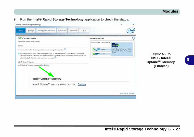
Modules
6
9. Run the Intel® Rapid Storage Technology application to check the status.
Figure 6 - 19IRST - Intel®
Optane™ Memory (Enabled)
Intel® Rapid Storage Technology 6 - 27

Modules
6
Disabling Intel® Optane™
If you need to disable Intel® Optane™ for any reason follow these instructions.
1. Run the Intel® Rapid Storage Technology application.2. Click Disable.
3. Click Yes when the message pops up.
Disabling Intel®
Optane™
Disable Intel® Op-tane™ if you want toreinstall/reset the sys-tem or update theIRST driver. See also“Clearing Intel® Op-tane™” on page 6 - 7.
Figure 6 - 20IRST - Intel®
Optane™ Memory (Disable)
Figure 6 - 21IRST - Yes to
Disable
6 - 28 Intel® Rapid Storage Technology

Modules
6
4. Restart the computer to complete the process.5. Run the Intel® Rapid Storage Technology application.6. The Status of Intel® Optane™ Memory is indicated in the Window.7. To enable Intel® Optane™ Memory follow the process indicated in “Enabling
Intel® Optane™” on page 6 - 25.
HDDs & Intel® Optane™ SSDs
Note that if your sys-tem’s HDD or Intel®Optane™ SSD is to betransferred to anothersystem for use for anyreason, you will needto disable Intel® Op-tane™ in IRST first.
Removal of any cov-er(s) and /or screw(s)violates the terms ofyour warranty.
Figure 6 - 22IRST - Intel®
Optane™ Memory (Status)
Intel® Rapid Storage Technology 6 - 29

Modules
6
Sound Blaster Cinema 3Install the Sound Blaster Cinema application is a suits of audio technologies whichallow you to configure the audio settings to your requirements for the best perfor-mance in games, music and movies.
Sound Blaster Cinema 3 Installation1. Before installing the driver make sure you have a working internet connec-
tion.2. Insert the Device Drivers & Utilities + User’s Manual disc into an attached
DVD drive.3. Click Option Drivers (button).4. Click 6.Install SBCinema AP > Yes.5. You will be prompted to enter your Activation keys (enter the keys and then
click Activate). If you have a working internet connection the system will confirm the activation.
6. Click OK, and you will then need to restart the computer.
Software Update
Check for the latest soft-ware updates by makingsure you are connectedto the internet and click-ing Software Updatefrom the Settingsmenu. Follow the in-structions provided toupdate the software.
6 - 30 Sound Blaster Cinema 3

Modules
6
Sound Blaster Cinema 3 ApplicationRun the Sound Blaster Cinema control panel from the notification area of the task-bar (or from Creative folder item in the Apps menu). Click on the tabs to access theany of the control panel menus.
Sound Blaster
Cinema 3 & HDMI
Note that the SoundBlaster Cinema 3 SBXPro Studio audio effectsdo not apply to audiogenerated through anHDMI connection.
Figure 6 - 23Sound Blaster
Cinema 3 Apps Menu & Taskbar Icon
Sound Blaster Cinema 3 6 - 31

Modules
6
Sound Blaster Cinema 3 PowerThe Sound Blaster Cinema 3 can be turned On/Off by clicking the Power Button
(when the power is off the icon will be dimmed ).
Figure 6 - 24Sound Blaster
Cinema 3 Power Button
Power Button
6 - 32 Sound Blaster Cinema 3
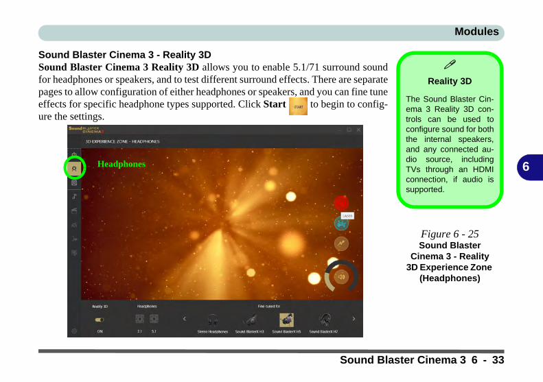
Modules
6
Sound Blaster Cinema 3 - Reality 3DSound Blaster Cinema 3 Reality 3D allows you to enable 5.1/71 surround soundfor headphones or speakers, and to test different surround effects. There are separatepages to allow configuration of either headphones or speakers, and you can fine tuneeffects for specific headphone types supported. Click Start to begin to config-ure the settings.
Reality 3D
The Sound Blaster Cin-ema 3 Reality 3D con-trols can be used toconfigure sound for boththe internal speakers,and any connected au-dio source, includingTVs through an HDMIconnection, if audio issupported.
Figure 6 - 25Sound Blaster
Cinema 3 - Reality 3D Experience Zone
(Headphones)
Headphones
Sound Blaster Cinema 3 6 - 33

Modules
6
You can scroll left or right through the headphones supported.
Volume can be adjusted by clicking on the dial.
Click on any of the effects buttons to test the effects.
Figure 6 - 26Sound Blaster
Cinema 3 Headphones
Figure 6 - 27Sound Blaster
Cinema 3Volume Dial
Figure 6 - 28Sound Blaster
Cinema 3Effect Buttons
6 - 34 Sound Blaster Cinema 3

Modules
6
The Speakers page has two tabs (3D Experience Zone and Speaker Calibration)which can be accessed by clicking the icons at the top right of the page.
Figure 6 - 29Sound Blaster
Cinema 3 - Reality 3D Experience Zone
(Speakers)
Speakers
Click to switch between 3D Experience Zone and Speaker Calibration
Sound Blaster Cinema 3 6 - 35

Modules
6
Click Test to run the speaker calibration test, and Stop once complete. Adjust thespeaker distances and levels from the controls at the bottom of the page.
Figure 6 - 30Sound Blaster
Cinema 3 - Speaker Calibration (Speakers)
6 - 36 Sound Blaster Cinema 3
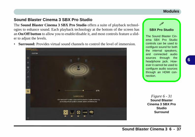
Modules
6
Sound Blaster Cinema 3 SBX Pro StudioThe Sound Blaster Cinema 3 SBX Pro Studio offers a suite of playback technol-ogies to enhance sound. Each playback technology at the bottom of the screen hasan On/Off button to allow you to enable/disable it, and most controls feature a slid-er to adjust the levels.
• Surround: Provides virtual sound channels to control the level of immersion.
SBX Pro Studio
The Sound Blaster Cin-ema SBX Pro Studiocontrols can be used toconfigure sound for boththe internal speakers,and connected audiosources through theheadphone jack. How-ever it cannot be used toconfigure audio sourcesthrough an HDMI con-nection.
Figure 6 - 31Sound Blaster
Cinema 3 SBX Pro Studio
Surround
Menu
Sound Blaster Cinema 3 6 - 37
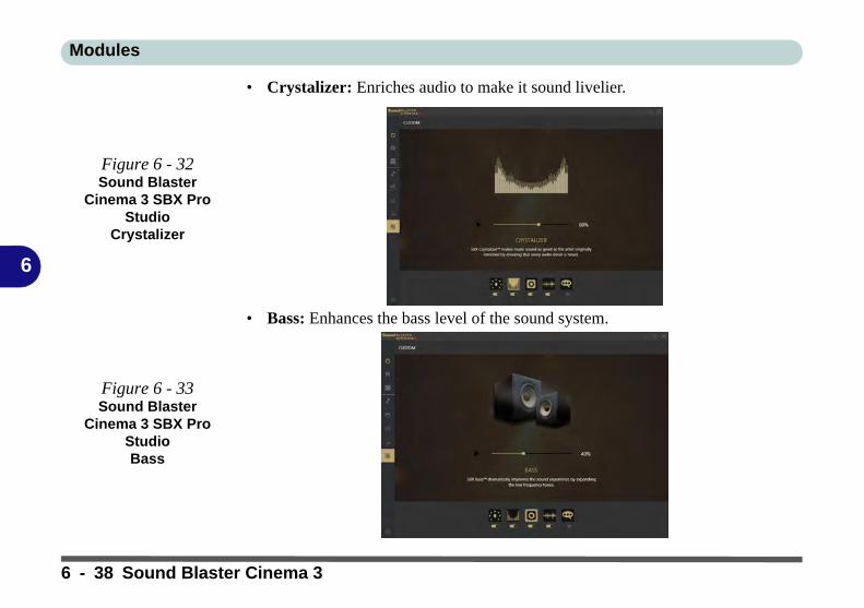
Modules
6
• Crystalizer: Enriches audio to make it sound livelier.
• Bass: Enhances the bass level of the sound system.
Figure 6 - 32Sound Blaster
Cinema 3 SBX Pro Studio
Crystalizer
Figure 6 - 33Sound Blaster
Cinema 3 SBX Pro StudioBass
6 - 38 Sound Blaster Cinema 3

Modules
6
• Smart Volume: Minimizes sudden volume changes to avoid the need for con-stant adjustment.
• Dialog Plus: Optimizes dialogue levels for movies etc.
Figure 6 - 34Sound Blaster
Cinema 3 SBX Pro Studio
Smart Volume
Figure 6 - 35Sound Blaster
Cinema 3 SBX Pro Studio
Dialog Plus
Sound Blaster Cinema 3 6 - 39

Modules
6
Sound Blaster Cinema 3 ProfilesThe Profile buttons on the left side of the screen give you preset settings to enhanceyour audio settings for Music, Movie, Game and Voice. You can choose Customto adjust the settings to your own set preferences.
Figure 6 - 36Sound Blaster
Cinema 3Profiles
MUSIC
MOVIE
GAME
VOICE
CUSTOM
6 - 40 Sound Blaster Cinema 3

Modules
6
Sound Blaster Cinema 3 SettingsClick the Settings button at the bottom left of the page to adjust the settings to yourpreferences.
Figure 6 - 37Sound Blaster
Cinema 3 - Settings
Sound Blaster Cinema 3 6 - 41

Modules
6
PC CameraUse the Fn + F10 key combination (see “Function Keys & Visual Indicators” onpage 1 - 24) or Control Center button to toggle power to the PC Camera module.
When the PC Camera is in use the LED indicator to the left of the camera will beilluminated (see Figure 1 - 2 on page 1 - 7).
Note that you need to use the Camera app in Windows to take pictures and cap-ture video.
2
6 - 42 PC Camera

Modules
6
Camera App1. Make sure the PC Camera is turned on by using the Fn + F10 key combination (or
Control Center button).2. Run the Camera app from the Start menu by clicking on the Camera app icon
(you can type “camera” into the search box to find the Camera app if it is not pinned to the Start menu).
3. The interface displays two buttons on the right of the screen; one for photo and one for video.
4. Simply click on the appropriate button to switch to either photo or video modes.5. You can use the buttons at the top to access the Photo collection, Self Timer or
Settings.
Figure 6 - 38Camera App Mode
Icons
Figure 6 - 39Camera Menu Bar
Photo Video
PC Camera 6 - 43

Modules
6
6. Click Settings to access the camera settings menu to make adjustments for Camera Button long key press function, Photo Aspect ratio, Framing grid, video recording frame rates, Flicker reduction and Digital video stabilization.
Figure 6 - 40Camera Settings
Camera Settings
The Self Timer may be set to take Photos after 2, 5 or 10 sec-onds and can also be set to continue taking pictures until thecamera button is pressed again.
The Aspect Ratio can be changed to those supported by thesystem.
You can use a Framing grid to help you line up pictures.
The Video recording resolution and frame rate can be set toany supported by the system. Note that capturing high resolu-tion video files requires a substantial amount of disk space foreach file. After recording video, check the video file size (right-click the file and select Properties) and the remaining free spaceon your hard disk (go to File Explorer, right-click the hard disk,and select Properties). If necessary you can remove the record-ed video file to a removable medium e.g. CD, DVD or USB Flashdrive.
If you need to reduce any screen flicker, change the settings inFlicker reduction to either e.g. 50Hz or 60Hz.
6 - 44 PC Camera

Modules
6
Taking Pictures/Capturing Video1. Make sure the PC Camera is turned on by using the Fn + F10 key combination (or
Control Center button).2. Run the Camera app from the Start menu by clicking on the Camera app icon
(you can type “camera” into the search box to find the Camera app if it is not pinned to the Start menu).
3. Click to select either photo or video modes.4. Click the photo icon to take a picture, and the camera icon will briefly turn yellow as
the picture is taken.5. Click on the video icon to start video capture (if video capture begins a timer
will appear at the bottom of the screen and the icon will turn yellow).6. To stop video capture click the video icon again.
Figure 6 - 41Video Camera Recording in
Process
PC Camera 6 - 45

Modules
6
7. Captured photos and videos will be saved to the Photos app stored in the Start menu (type Photos into the search box if you cannot find the app).
Figure 6 - 42Photo App
(For Captured Photos & Videos)
6 - 46 PC Camera
Modules
6
Trusted Platform Module(Optional)The TPM security chip allows you to create and manage digital certificates for userand platform authentication. This type of security is usually administered withinlarge enterprises and organizations, and therefore requires implementation by a sys-tem administrator before users can access security features.
Individual users can use the TPM as an authentication with the fingerprint reader.
Make sure you have administrator’s rights to your computer, and have a Windowspassword enabled for full security protection. In addition Make sure you preparea removable media (e.g. a USB flash drive) to store passwords etc. before begin-ning the TPM initialization process.
Before setting up the TPM functions you must initialize the security platform.
Trusted Platform Module 6 - 47
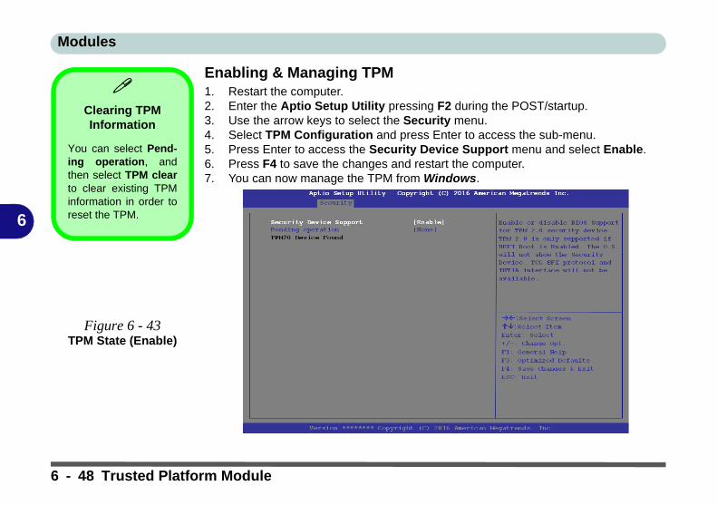
Modules
6
Enabling & Managing TPM1. Restart the computer.2. Enter the Aptio Setup Utility pressing F2 during the POST/startup.3. Use the arrow keys to select the Security menu.4. Select TPM Configuration and press Enter to access the sub-menu.5. Press Enter to access the Security Device Support menu and select Enable.6. Press F4 to save the changes and restart the computer.7. You can now manage the TPM from Windows.
Clearing TPM Information
You can select Pend-ing operation, andthen select TPM clearto clear existing TPMinformation in order toreset the TPM.
Figure 6 - 43TPM State (Enable)
6 - 48 Trusted Platform Module

Modules
6
TPM Management in WindowsYou can manage your TPM settings from within Windows:
1. Go to the Control Panel.2. Click BitLocker Drive Encryption (System and Security).3. Click TPM Administration.
Figure 6 - 44BitLocker Drive
Encryption (TPM
Administration)
Trusted Platform Module 6 - 49

Modules
6
4. The TPM Management window allows you to configure the TPM within Windows. As TPM is usually administered within large enterprises and organizations, your system administrator will need to assist you in managing the information here.
Figure 6 - 45Trusted Platform
Module (TPM) Management on Local Computer Administration
6 - 50 Trusted Platform Module

Modules
6
TPM Actions1. Click Prepare the TPM and follow the instructions in the Wizard to prepare the
TPM (this will probably require a restart of the computer and confirmation of the setting changes after restart by pressing the appropriate F key).
2. After the restart the TPM will be prepared and you can then use the Actions menu to Turn TPM off, Change Owner Password, Clear TPM or Reset TPM Lockout.
3. A wizard will help take you through any setup steps.
Figure 6 - 46TPM Actions Menu
Trusted Platform Module 6 - 51

Modules
6
BitLockerBitLocker Drive Encryption can be used in conjunction with the TPM to encryptdata on the disk. Access the Microsoft BitLocker Drive Encryption control panelapplet from the Windows control panel (System and Security).
1. Click Turn on Bit Locker.2. Follow the on-screen instructions to setup BitLocker, and make sure you have a
removable media (e.g. a USB flash drive) to store saved recovery keys etc.
Figure 6 - 47BitLocker Drive
Encryption
6 - 52 Trusted Platform Module

Modules
6
3G/4G Module(For Models A & B Only)If you have included an optional UMTS/HSPA+ based 3G Module (Universal Mo-bile Telecommunications System or High Speed Packet Access) module or LTE(Long Term Evolution) 4G module (see “Communication” on page D - 3 for spec-ification details) in your purchase option, you do not require a driver/applicationinstallation for Windows 10. Follow the instructions overleaf to install the USIMcard (which will be provided by your service provider), and then use the CharmsBar Wireless icon to access the 3G/4G network in the same manner as the WLAN.
Wireless Device
Operation Aboard Aircraft
The use of any portableelectronic transmissiondevices aboard aircraftis usually prohibited.Make sure the WLAN,Bluetooth and 3G/4Gmodule(s) are OFF (orthe system is in Air-plane Mode) if you areusing the computeraboard aircraft (seeTable 1 - 6, on page 1 -24).
Important Notice
If your purchase option includes both Wireless LAN and 3G/4G modules, then the appro-priate antennas will be installed. Note that In order to comply with FCC RF exposure com-pliance requirements, the antenna must not be co-located or operate in conjunction withany other antenna or transmitter.
Important Notice - 3G/4G & Bluetooth/Wireless LAN Modules
In order to comply with FCC regulations you should NOT operate the 3G/4G module andthe Bluetooth/Wireless LAN modules at the same time as this may disrupt radio frequency,and cause interference. When the 3G/4G module is powered on, make sure that the Blue-tooth/Wireless LAN modules are powered off.
3G/4G Module 6 - 53

Modules
6
3G/4G Module USIM Card Installation (for Models A & B)Follow the instructions below to install the USIM card (which will be supplied byyour service provider) which requires the removal of the battery first.
1. Turn the computer off, and turn it over.2. Slide the latch in the direction of the arrow, and then slide latch in the
direction of the arrow and hold it in place.3. While holding the latch in place, pull the battery up at point in the direction
of the arrow to remove the battery .4. Insert the USIM card (see overleaf).5. Reinsert the battery (see page 6 - 56).
Power Safety
Warning
Before you undertake anyinstallation procedures,make sure that you haveturned off the power, anddisconnected all peripher-als and cables (includingtelephone lines).
Figure 6 - 48Battery Removal &
USIM Card Insertion
1 2
2 34 5
6
123
4
5
6
6 - 54 3G/4G Module

Modules
6
3G/4G Module USIM Card InstallationInsert the USIM card as illustrated below (pay careful attention to the orientationof the card as the gold contact side of the card should face downwards) until it clicksfully into position. To eject the card simply press it until it ejects, but do not attemptto eject the card while connected to a 3G/4G network (see below).
USIM Card Orientation
Note that the USIMcard’s readable side(with the gold-coloredcontacts) should facedownwards as illustrat-ed.
Figure 6 - 49USIM Card Insertion
1
USIM Card Ejection
Simply press on the USIM card to eject it, however do not do this while a connection is inprogress. If you do eject the card while a 3G/4G connection is ongoing, you will need to shutdown the system, reinsert the USIM card, restart the system and then reestablish the 3G/4Gconnection.
If you wish to change USIM cards then you will need to shut the system down, reinsert theUSIM card, restart the system and then reestablish the 3G/4G connection.
1
3G/4G Module 6 - 55

Modules
6
Battery Insertion1. Orientate the battery as illustrated below and align it with the edges of the bat-
tery compartment.2. Push the battery in the direction of the arrow to insert it into the compartment (it
should click into place).3. Slide the latch in the direction of the arrow into the lock position.
Figure 6 - 50Battery Insertion
1
2
3
1
2 3
6 - 56 3G/4G Module

Modules
6
3G/4G Configuration in Windows 10You can configure a 3G/4G connection as below, however make sure the system isnot in Airplane Mode before configuration begins. You can connect to a 3G/4G con-nection in much the same way as the WLAN connection.
1. Click the Settings item in the Start Menu and then click Network and Internet.2. Click Cellular and a list of available access points will appear (if you have issues
connecting to the cellular network see the sidebar).3. Click the access point and click Connect.4. The system will connect to your network.5. Connected will appear under the connection.6. You can then access the internet, download e-mail etc. as per any internet
connection.7. To disconnect you can select the connection and click Disconnect.8. You need to use Airplane Mode aboard aircraft.9. You can also click the Wireless icon in the notification area of the taskbar, click
Cellular and double-click an access point connect to access the connection information.
Connecting to the Cellular Network
Manually
Usually the InternetAPN (Access PointName) is set automati-cally, however if yourcellular data connectionisn't working, you shouldtry manually entering anew Internet APN basedon your location andmobile operator. Seepage 7 - 16 for details.
3G/4G Module 6 - 57

Modules
6
6 - 58

Troubleshooting
7
Chapter 7: Troubleshooting
OverviewShould you have any problems with your computer, before consulting your service representative, you may wantto try to solve the problem yourself. This chapter lists some common problems and their possible solutions. Thiscan’t anticipate every problem, but you should check here before you panic. If you don’t find the answer in thesepages, make sure you have followed the instructions carefully and observed the safety precautions in the preface.If all else fails, talk to your service representative. You should also make a record of what happened and whatremedies you tried.
Of course, if something goes wrong, it will happen at the most inconvenient time possible, so you should previewthis section just in case. If, after you’ve tried everything, and the system still won’t cooperate, try turning it offfor a few minutes and then rebooting. You will lose any unsaved data, but it may start working again. Then callyour service representative.
Overview 7 - 1

Troubleshooting
7
Basic Hints and TipsMany of the following may seem obvious but they are often the solution to a problem when your computer ap-pears not to be working.
• Power - Is the computer actually plugged into a working electrical outlet? If plugged into a power strip, make sure it is actually working. Check the LED Power Indicators (see “LCD Panel Open - Model B” on page 1 - 8) to see the computer’s power status.
• Connections - Check all the cables to make sure that there are no loose connections anywhere.
• Power Savings - Make sure that the system is not in Hibernate or Sleep mode by pressing the keys config-ured in your Power Options (see “Configuring the Power Buttons” on page 3 - 9), the Fn + F12 key com-bination, or power button to wake-up the system.
• Brightness - Check the brightness of the screen by pressing the Fn + F8 and F9 keys to adjust the bright-ness (see Table , on page 1 - 24).
• Display Choice - Press Fn + F7 to make sure the system is not set to “external only” display.
• Boot Drive - Make sure there are no optical media and/or USB storage devices in any connected drive.
7 - 2 Basic Hints and Tips

Troubleshooting
7
Backup and General Maintenance• Always backup your important data, and keep copies of your OS and programs safe, but close to hand.
Don’t forget to note the serial numbers if you are storing them out of their original cases, e.g. in a CD wal-let.
• Run maintenance programs on your hard disk and OS as often as you can. You may schedule these pro-grams to run at times when you are not using your computer. You can use those that are provided free with your OS, or buy the more powerful dedicated programs to do so.
• Write down your passwords and keep them safe (away from your computer). This is especially important if you choose to use a Boot password for the SCU (see “Security Menu” on page 5 - 11).
• Keep copies of vital settings files such as network, dialup settings, mail settings etc. (even if just brief notes).
Bottom Cover Removal Warning
Users should not remove any cover(s) and /or screw(s) for the purposes of device upgrade as this may violate the terms ofyour warranty. If you need to replace/remove the hard disk/RAM/optical device etc., for any reason, please contact your dis-tributor/supplier for further information.
Backup and General Maintenance 7 - 3

Troubleshooting
7
Viruses• Install an Anti-Virus program and keep the definitions file (the file which tells your program which viruses
to look for) up to date. New computer viruses are discovered daily, and some of them may seriously harm your computer and cause you to lose data. Anti-Virus programs are commercially available and the defini-tions file updates are usually downloadable directly from the internet.
• Be careful when opening e-mail from sources you don’t know. Viruses are often triggered from within e-mail attachments so take care when opening any attached file. You can configure most Anti-Virus pro-grams to check all e-mail attachments. Note: You should also beware of files from people you know as the virus may have infected an address book and been automatically forwarded without the person’s knowl-edge.
• Keep a “Bootable CD-ROM/DVD-ROM/USB storage device” (this CD/DVD/USB device provides basic information which allows you to startup your computer) handy. You may refer to your OS’s documentation for instructions on how to make one, and many Anti-Virus programs will also provide such a disk (or at least instructions on how to make one).
7 - 4 Viruses
Troubleshooting
7
Upgrading and Adding New Hardware/Software• Do not be tempted to make changes to your Windows Registry unless you are very sure of what you are
doing, otherwise you will risk severely damaging your system.
• Don’t open your computer or undertake any repair or upgrade work if as this may violate the terms of your warranty.
• Read the documentation. We can assume, since you are reading this that you are looking at the computer’s manual, but what about any new peripheral devices you have just purchased? Many problems are caused by the installation of new hardware and/or software. Always refer to the documentation of any new hardware and/or software, and pay particular attention to files entitled “READ ME” or “READ ME FIRST”.
• When installing a new device always make sure the device is powered on, and in many cases you will need to restart the computer. Always check that all the cables are correctly connected.
• Make sure you have installed the drivers for any new hardware you have installed (latest driver files are usually available to download from vendor’s websites).
• Thoroughly check any recent changes you made to your system as these changes may affect one or more system components, or software programs. If possible, go back and undo the change you just made and see if the problem still occurs.
Upgrading and Adding New Hardware/Software 7 - 5

Troubleshooting
7
• Don’t over complicate things. The less you have to deal with then the easier the source of the problem may be found; Example - if your computer has many devices plugged into its ports, and a number of programs running, then it will be difficult to determine the cause of a problem. Try disconnecting all of the devices and restarting the computer with all the peripheral devices unplugged. A process of elimination (adding and removing devices and restarting where necessary) will often find the source of a problem, although this may be time consuming.
7 - 6 Upgrading and Adding New Hardware/Software
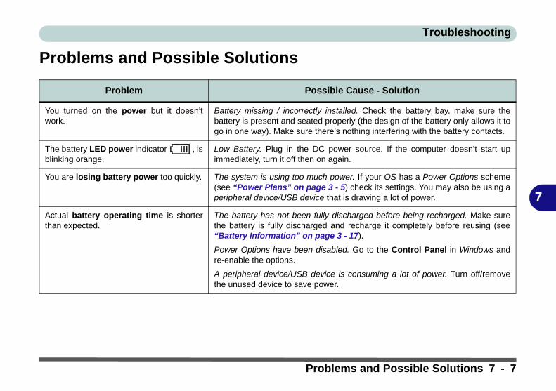
Troubleshooting
7
Problems and Possible Solutions
Problem Possible Cause - Solution
You turned on the power but it doesn’twork.
Battery missing / incorrectly installed. Check the battery bay, make sure thebattery is present and seated properly (the design of the battery only allows it togo in one way). Make sure there’s nothing interfering with the battery contacts.
The battery LED power indicator , isblinking orange.
Low Battery. Plug in the DC power source. If the computer doesn’t start upimmediately, turn it off then on again.
You are losing battery power too quickly. The system is using too much power. If your OS has a Power Options scheme(see “Power Plans” on page 3 - 5) check its settings. You may also be using aperipheral device/USB device that is drawing a lot of power.
Actual battery operating time is shorterthan expected.
The battery has not been fully discharged before being recharged. Make surethe battery is fully discharged and recharge it completely before reusing (see“Battery Information” on page 3 - 17).
Power Options have been disabled. Go to the Control Panel in Windows andre-enable the options.
A peripheral device/USB device is consuming a lot of power. Turn off/removethe unused device to save power.
Problems and Possible Solutions 7 - 7
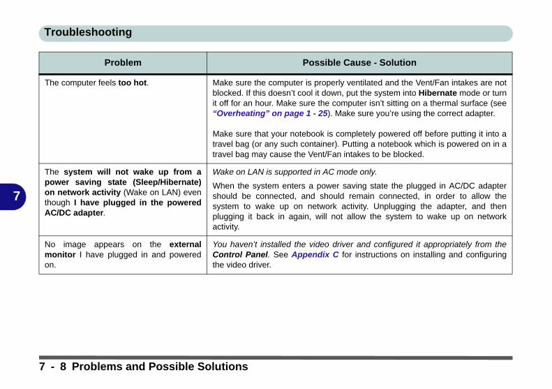
Troubleshooting
7
The computer feels too hot. Make sure the computer is properly ventilated and the Vent/Fan intakes are notblocked. If this doesn’t cool it down, put the system into Hibernate mode or turnit off for an hour. Make sure the computer isn’t sitting on a thermal surface (see“Overheating” on page 1 - 25). Make sure you’re using the correct adapter.
Make sure that your notebook is completely powered off before putting it into atravel bag (or any such container). Putting a notebook which is powered on in atravel bag may cause the Vent/Fan intakes to be blocked.
The system will not wake up from apower saving state (Sleep/Hibernate)on network activity (Wake on LAN) eventhough I have plugged in the poweredAC/DC adapter.
Wake on LAN is supported in AC mode only.
When the system enters a power saving state the plugged in AC/DC adaptershould be connected, and should remain connected, in order to allow thesystem to wake up on network activity. Unplugging the adapter, and thenplugging it back in again, will not allow the system to wake up on networkactivity.
No image appears on the externalmonitor I have plugged in and poweredon.
You haven’t installed the video driver and configured it appropriately from theControl Panel. See Appendix C for instructions on installing and configuringthe video driver.
Problem Possible Cause - Solution
7 - 8 Problems and Possible Solutions

Troubleshooting
7
Nothing appears on screen. The system is in a power saving mode. Toggle the sleep/resume keycombination, Fn + F12 (see “Configuring the Power Buttons” on page 3 - 9).
The screen controls need to be adjusted. Toggle the screen control keycombinations Fn + F8/F9. If you’re connected to an external monitor, make sureit’s plugged in and turned on. You should also check the monitor’s ownbrightness and contrast controls.
The computer is set for a different display. Toggle the screen display keycombination, Fn + F7. If an external monitor is connected, turn it on.
The screen saver is activated. Press any key or touch the TouchPad.
You forget the boot password. If you forget the password, you may have to discharge the battery of the CMOS.Contact your service representative for help.
Problem Possible Cause - Solution
Password Warning
If you choose to set a boot password, NEVER forget your password. The consequences of this could be serious. If you cannotremember your boot password you must contact your vendor and you may lose all of the information on your hard disk.
Problems and Possible Solutions 7 - 9

Troubleshooting
7
The sound cannot be heard or the volumeis very low.
The volume might be set too low. Check the volume control in the VolumeControl Panel in the Windows notification area, or use the key combination Fn+ F5 and F6 (see “Keyboard Backlight LED” on page 1 - 15) to adjust.
Unwelcome numbers appear when typing. Num Lock is turned ON (see “LCD Panel Open - Model B” on page 1 - 8).
The system freezes or the screen goesdark.
The system’s power saving features have timed-out. Use the AC/DC adapter,press the sleep (Fn + F12) key combination, or press the power button if noLEDs are lit.
The fingerprint reader has problemsscanning fingers.
When fingers are wet or sweaty the software application may have difficultyreading a scanned finger. Make sure your fingers are clean and dry whenattempting to scan them across the sensor for detection.
Problem Possible Cause - Solution
Other Keyboards
If your keyboard is damaged or you just want to make a change, you can use any standard USB keyboard. The system willdetect and enable it automatically. However special functions/hot keys unique to the system’s regular keyboard may notwork.
7 - 10 Problems and Possible Solutions

Troubleshooting
7
The system never goes into a powersaving mode.
Power Options features are not enabled. Go to the Windows Power Optionsmenu and enable the features you prefer (see “Power-Saving States” onpage 3 - 7). Make sure you have enabled Hibernate mode from the controlpanel.
The Wireless LAN/Bluetooth modulescannot be detected.
The modules are off as the computer is in Airplane Mode. Check the LEDindicator to see if it is in Airplane Mode (see “LCD Panel Open - Model B”on page 1 - 8). Use the Fn + F11 key combination to toggle Airplane Mode on/off (see Table , on page 1 - 24).
The PC Camera module cannot bedetected.
The module is off. Press the Fn + F10 key combination in order to enable themodule (see “Keyboard Backlight LED” on page 1 - 15). Run the cameraapplication to view the camera picture.
The Wireless LAN/Bluetooth modulescannot be configured.
The driver(s) for the module(s) have not been installed. Make sure you haveinstalled the driver for the appropriate module (see the instructions for theappropriate module in “Wireless LAN Module” on page 6 - 10 and/or“Bluetooth & WLAN Combo Module” on page 6 - 17).
A file cannot be copied to/from aconnected Bluetooth device.
The transfer of data between the computer and a Bluetooth enabled device issupported in one direction only (simultaneous data transfer is notsupported). If you are copying a file from your computer to a Bluetooth enableddevice, you will not be able to copy a file from the Bluetooth enabled device toyour computer until the file transfer process has been completed
Problem Possible Cause - Solution
Problems and Possible Solutions 7 - 11

Troubleshooting
7
My internal microphone seems to bedisabled and/or I can still hear soundfrom the speakers even though I haveplugged headphones into the headphonejack.
You have not enabled “Separate all input jacks as independent input devices” inDevice advanced settings.
No sound can be heard through an HDMIconnected display.
You have not configured the HDMI audio output. See “HDMI AudioConfiguration” on page C - 7.
The Sound Blaster Cinema 3 SBX ProStudio audio effects don’t work when thesystem is connected to an externaldisplay through an HDMI/ Display Portcable.
Note that Sound Blaster Cinema 3 SBX Pro Studio audio effects will be disabledwhen you are connecting to an external display through an HDMI or Display Portconnection. See “HDMI Audio Configuration” on page C - 7.
When using a Bluetooth headset theaudio appears to be mono and notstereo.
This is a common issue with Bluetooth headsets. To resolve this issue do thefollowing (you will need to repeat this procedure after every boot up, restart,or when the system resumes from hibernation):
1. Go to the Devices & Printers control panel in Windows.2. Double-click the Bluetooth headset.3. Click Connect to complete the stereo connection.OR1. Go to the Sound control panel in Windows.2. Right-click (in the Playback tab) the Bluetooth Stereo Audio device (the
default device is Headset).3. Click Connect to complete the stereo connection.
Problem Possible Cause - Solution
7 - 12 Problems and Possible Solutions

Troubleshooting
7
A file being copied to/from a connectedBluetooth device appears to betransferring very slowly.
You may have the Bluetooth control panel (Settings > Devices > Bluetooth)open. When transferring data between the computer and a Bluetooth enableddevice, make sure that the Bluetooth control panel is closed.
Problem Possible Cause - Solution
Bluetooth Control Panel
(Settings > Devices)
Close the Bluetooth controlpanel (pictured on the right)when transferring data be-tween the computer and aBluetooth enabled device.
Problems and Possible Solutions 7 - 13
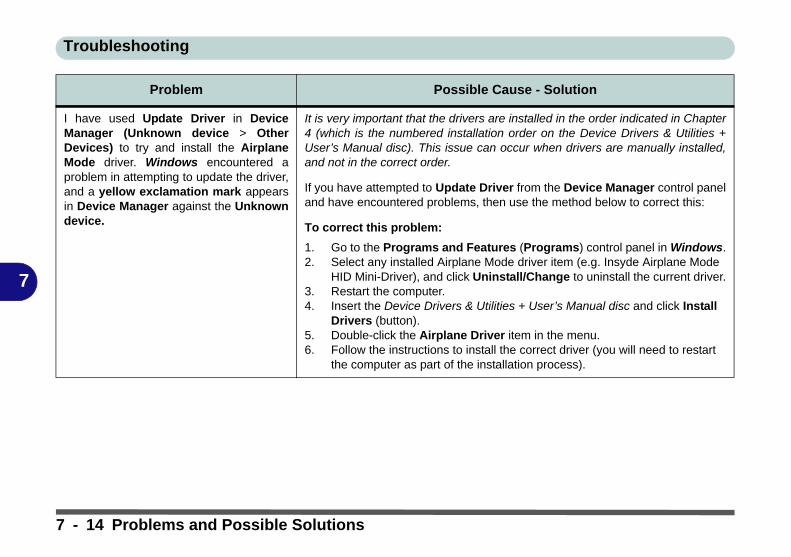
Troubleshooting
7
I have used Update Driver in DeviceManager (Unknown device > OtherDevices) to try and install the AirplaneMode driver. Windows encountered aproblem in attempting to update the driver,and a yellow exclamation mark appearsin Device Manager against the Unknowndevice.
It is very important that the drivers are installed in the order indicated in Chapter4 (which is the numbered installation order on the Device Drivers & Utilities +User’s Manual disc). This issue can occur when drivers are manually installed,and not in the correct order.
If you have attempted to Update Driver from the Device Manager control paneland have encountered problems, then use the method below to correct this:
To correct this problem:
1. Go to the Programs and Features (Programs) control panel in Windows.2. Select any installed Airplane Mode driver item (e.g. Insyde Airplane Mode
HID Mini-Driver), and click Uninstall/Change to uninstall the current driver.3. Restart the computer.4. Insert the Device Drivers & Utilities + User’s Manual disc and click Install
Drivers (button).5. Double-click the Airplane Driver item in the menu.6. Follow the instructions to install the correct driver (you will need to restart
the computer as part of the installation process).
Problem Possible Cause - Solution
7 - 14 Problems and Possible Solutions
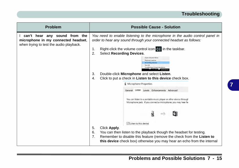
Troubleshooting
7
I can’t hear any sound from themicrophone in my connected headset,when trying to test the audio playback.
You need to enable listening to the microphone in the audio control panel inorder to hear any sound through your connected headset as follows:
1. Right-click the volume control icon in the taskbar.2. Select Recording Devices.
3. Double-click Microphone and select Listen.4. Click to put a check in Listen to this device check box.
5. Click Apply.6. You can then listen to the playback though the headset for testing.7. Remember to disable this feature (remove the check from the Listen to
this device check box) otherwise you may hear an echo from the internal
Problem Possible Cause - Solution
Problems and Possible Solutions 7 - 15
Troubleshooting
7
Resolving the “Can’t connect to this network” issue with the 3G/4G Module(For Models A & B Only)1. If you have issues connecting to the cellular network when you are attempting to use the 3G/4G network then
you may need to manually connect to the Internet access point name (APN).2. Usually the Internet APN is set automatically, however if your cellular data connection isn't working, you should
try manually entering a new Internet APN based on your location and mobile operator.3. To find your APN settings contact your mobile operator directly (or of you can connect to a WiFi network on your
PC, or have a phone handy, try searching online to find the Internet APN settings for your mobile operator).4. See http://windows.microsoft.com/en-us/windows-10/cellular-settings or search the Microsoft website for
"Windows 10 cellular settings".
7 - 16 Problems and Possible Solutions
Troubleshooting
7
Intel® Optane™ NotesIntel® Optane™ is a combination of a compatible memory device and Intel Rapid Technology software. Thiscombination is designed to speed up your system performance. However note the following;
• The SATA Mode should be set BEFORE installing an operating system, and after you have backed up all necessary files and data (see sidebar). See “Setting Up SATA Mode (Optane™ or AHCI)” on page 6 - 2 for details. Make sure you install the Intel Rapid Storage Technology application if you have set the SATA Mode to Intel RST Premium, or to AHCI (see “IRST Driver Installation” on page 6 - 23).
• It is very important to make sure that when you create a hard disk drive partition when installing Windows for an Intel® Optane™ system, that you leave at least a minimum of 5MB of unallocated space (note this is 5MB only, not GB).
• After setting the SATA mode to Intel® Optane™ and installing the Intel® Rapid Storage Technology application, DO NOT uninstall the Intel® Rapid Storage Technology application.
• If you are reinstalling a system that has previously been setup in Intel RST Premium mode, make sure you have cleared the Intel Optane Memory (see “Clearing Intel® Optane™” on page 6 - 7). If you haven’t cleared the Optane setup you may not find a suitable hard disk drive partition on which to reinstall an operating system.
• If you need to reinstall an operating system, uninstall the IRST driver/application or swap the hard disk drive (or Intel® Optane™ SSD) make sure you have cleared the Intel Optane Memory (see “Clearing Intel® Optane™” on page 6 - 7).
Problems and Possible Solutions 7 - 17

Troubleshooting
7
7 - 18

Interface (Ports & Jacks)
A
Appendix A: Interface (Ports & Jacks)
OverviewThe following chapter will give a quick description of the ports & jacks which allow your computer to commu-nicate with external devices, connect to the internet etc.
Interface (Ports & Jacks) A - 1

Interface (Ports & Jacks)
A
Ports and Jacks
Item Description
Card Reader The card reader allows you to use the following digital storage cards:
MMC (MultiMedia Card) / RSMMCSD (Secure Digital) / Mini SD / SDHC / SDXC (up to UHS-II)
Push the card into the slot and it will appear as a removable device.
DC-In Jack Plug the supplied AC/DC adapter into this jack to power your computer.
External Monitor (VGA) Port
This port allows you to connect an external monitor, or Flat Panel Display, to get dual video orsimultaneous display on the LCD and external monitor/FPD.
HDMI-Out Port The HDMI-Out (High-Definition Multimedia Interface) port is an audio/video connectorinterface for transmitting uncompressed digital streams. This allows you to connect an externalmonitor, TV or Flat Panel Display etc. as a display device (see “Attaching Other Displays” onpage C - 27) by means of a HDMI cable. Note that HDMI carries both audio and videosignals.
Headphone-Out Jack Headphones or speakers may be connected through this jack. Note: Set your system’s volumeto a reduced level before connecting to this jack.
A - 2 Interface (Ports & Jacks)

Interface (Ports & Jacks)
A
Microphone-In Jack Plug an external microphone in to this jack to record on your computer.
Mini DisplayPort 1.2 The Mini DisplayPorts are a miniatuarized version of the DisplayPort, which is a digital displayinterface standard that allows a digital audio/video interconnect, between the computer and itsexternal display or a home-theater system.
RJ-45 LAN Jack This port supports LAN (Network) functions.Note: Broadband (e.g. ADSL) modems usually connect to the LAN port.
Security Lock Slot To prevent possible theft, a Kensington-type lock can be attached to this slot. Locks can bepurchased at any computer store.
Item Description
Mini DisplayPort Cables
When using cables connected to the Mini DisplayPort, try to make sure that the cables are not bentexcessively, as bending the cables may cause signal problems.
Interface (Ports & Jacks) A - 3

Interface (Ports & Jacks)
A
USB 2.0/1.1 Port
USB 3.0 (USB 3.1 Gen 1 Type A) Port
USB 3.0 (USB 3.1 Gen 1 Type C) Port
USB 3.1 (USB 3.1 Gen 2 Type A & Type C) Port
(Factory Option)
USB 2.0 compatible ports (USB 2.0 is fully USB 1.1 compliant) are for low-speed peripheralssuch as keyboards, mice or scanners, and for high-speed peripherals such as external HDDs,digital video cameras or high-speed scanners etc. Devices can be plugged into the computer, andunplugged from the computer, without the need to turn the system off (if the power rating of yourUSB device is 500mA or above, make sure you use the power supply which comes with thedevice).
USB 3.0 ports capable of 5Gbps (SuperSpeed) are classified as USB 3.1 Gen 1 and USB 3.1Gen 2 ports are capable of 10Gbps SuperSpeed+.
There is one USB 2.0 port, two USB 3.1 Gen 1 (Type A) ports and one USB 3.1 Gen 1 (TypeC) port (the Type C port is the smaller sized USB port).
One USB 3.1 Gen 2 port (Type A) and one USB 3.1 Gen 2 port (Type C) are available as afactory option. These ports are shared with the existing USB 3.1 Gen 1 Type A and Type Cports, and are capable of 10Gbps SuperSpeed+ for a single device, or if two devices areplugged in to both USB 3.1 (Gen 2) ports, the bandwidth will be shared between the ports.
Note: The maximum amount of current supplied by USB Type-C ports is 500 mA for USB2.0/900mA for USB 3.1
Item Description
A - 4 Interface (Ports & Jacks)

Control Center & Flexikey®
B
Appendix B: Control Center & Flexikey®OverviewThe following chapter will give a quick description of the functions of the Control Center & Flexikey® appli-cations.
Control CenterThe Control Center gives quick access to frequently used controls, power management features and enables youto quickly turn modules on/off. Click the Control Center icons to toggle the appropriate function, or hold themouse button down and move the dial control where applicable. Certain functions will automatically be adjustedwhen a power mode is selected. The Control Center in Windows 10 works under the Desktop app and not underthe Start screen.
Flexikey®The Flexikey® application is a quick hotkey configuration application, which allows you to assign a single keyto launch multiple key combinations, or to launch programs and applications, to create text macros and todisable certain keys. The application can also be used to configure the mouse buttons to create hotkeys forgaming etc. All the configuration settings are retained under (up to12) profiles to which the settings are applied.Click Flexikey® in the Gaming section of the Control Center, or the click the icon in the notificationarea of the taskbar, to launch the application.
Overview B - 1

Control Center & Flexikey®
B
Figure B - 1 - Control Center
Control Center Access
To run the Control Center press the Fn + Esc key combination, or double-click the icon in thenotification area of the taskbar. Close the Control Center by clicking the close icon in the topright of the panel (move the cursor onto the top right corner of the panel to highlight it).
Flexikey® Access
The Flexikey® is accessed from within the Control Center by clicking Flexikey® in the Gamingsection of the Control Center.
B - 2 Overview

Control Center & Flexikey®
B
Power ModesYou can set a Power Mode by clicking the appropriate icon at the top of the Control Center. Each powermode will affect the Power Conservation Mode, Airplane Mode, Power Plan and PC camera power etc.
You can click a Control Center icon to set an overall power mode and then click individual icons in theControl Center to power on/off the Touchpad and PC camera.
Table B - 1- Power Modes
Modes Quiet Power Saving Performance Entertainment
Icon
Power Plan Balanced Power Saver High Performance Balanced
Power Conservation Mode Balance Energy Star Performance Balance
PC Camera ON OFF ON ON
TouchPad ON ON ON ON
Airplane Mode OFF ON OFF OFF
Overview B - 3

Control Center & Flexikey®
B
Control Center MenusThe Control Center contains 3 menu headings (System Program, Device and Gaming) under the PowerModes. Click the menu headings and then click any of the buttons outlined on the following pages.
Figure B - 2 - Control Center Menus
B - 4 Overview

Control Center & Flexikey®
B
Power Status (System Program)
The Power Status icon will show whether you are currently powered by the battery, or by the AC/DC adapterplugged in to a working power outlet. The power status bar will show the current battery charge state.
Brightness (System Program) The Brightness icon will show the current screen brightness level. You can use the slider to adjust the screenbrightness or the Fn + F8/F9 key combinations, or use the Fn+ F2 key combination to turn off the LED backlight(press any key to turn it on again).
Volume (System Program)The Volume icon will show the current volume level. You can use the slider to adjust the Volume or the Fn +F5/F6 key combinations, or use the Fn+ F3 key combination to mute the volume.
Fan Speed (System Program)You can set the fan speed to Maximum (full power), Automatic or Custom from this menu item. The fan speedwill adjust itself automatically to control the heat of the CPU. However you can adjust the setting to maximumif you prefer. Select Custom and click on the sliders to adjust the settings to your preference, however these set-tings can be overridden by the system, as a safety precaution, if it requires heavier use of the fan.
Custom Settings
Click Save to retain customized settings, or Reset to select default settings.
Overview B - 5

Control Center & Flexikey®
B
Power Conservation (System Program)This system supports Power Saving power management features that place computers (CPU, hard drive, etc.) into a low-power sleep modes after a desig-nated period of inactivity (see “Power Conservation Modes” on page 3 - 12). Click either the Performance,Balanced or Power Saving button.
Sleep Button (System Program) Click either the Hibernate or Sleep buttons to have the computer enter the selected power-saving mode (see“Power-Saving States” on page 3 - 7).
Desktop Background (System Program) Clicking the Desktop Background button will allow you to change the desktop background picture.
Display Switch (System Program) Click the Display Switch button to access the menu (or use the + P key combination) and select the appro-priate attached display mode.
Time Zone (System Program) Clicking the Time Zone button will access the Date and Time Windows control panel.
B - 6 Overview

Control Center & Flexikey®
B
Backlight Keyboard (Device) Click the numbers under the Backlight Keyboard icon to
TouchPad/Camera (Device) Click either of these buttonsto toggle the TouchPad or camera module’s power status. The icon will appear dimmed when it is off. Note thatthe power status of the camera module is also effected by the Power Mode selected (see Table B - 1, on page B- 3).
Caps Lock/Scroll Lock/ Number Lock/Airplane ModeClick the button to toggle the appropriate lock mode and Airplane Mode.
Left Windows Key (Gaming) Click Disable to disable the Windows Key on the left side of the keyboard. This may be useful if you are usingthe gaming keys (W, A, S & D) and wish to avoid accidentally triggering menus with the Windows Key.
Flexikey® (Gaming) Click the button to access the Flexikey® application.
Overview B - 7

Control Center & Flexikey®
B
Flexikey® ApplicationClick the button in the Control Center, or the click the icon in the notification area of the taskbar,to access the Flexikey® application.
ProfilesThe menus on the left side of the application relate to Profiles. You can Add or Delete Profiles (you can main-tain 12 active Profiles), Export and Import profiles from the menus. If you double-click on a Profile you canchange the Profile Name, and change an Image file (images created using PNG files).
Figure B - 3 - Flexikey® - Profiles
Windows Key &
P Key
Note that you canassign actions toany keyboard keyexcept the Win-dows key and Pkey.
B - 8 Flexikey® Application

Control Center & Flexikey®
B
Flexikey® Application Features
• EXPRESS KEY - This feature allows you to configure a single key to send multiple key combinations or to create more useful shortcut keys. This is useful in gaming or when using applications which have a complex set of keyboard shortcuts.
• LAUNCH APP - This simply assigns single keys to launch any program’s or application’s executable file.
• EXPRESS TEXT - With this you can assign single keys to send commonly used strings of text.
• DISABLE - Use this function to disable any keyboard keys.
• STATISTICS - Use this to quickly record keys in use in any application, and to disable unused keys.
Keyboard and Mouse SettingsClick Enable to create settings for the keyboard and/or mouse by clicking the button on the top left of the screen(e.g. you may wish to create a profile with settings only for the mouse or keyboard). Clicking on the keyboardor mouse icons will allow you to access the settings page for the either the keyboard or mouse.
Figure B - 4 - Enable Keyboard & Mouse / Language Selection
Language InterfaceYou can change the language interface by right-clicking the icon in the notification area of the taskbar andselecting the language from the menu.
Flexikey® Application B - 9

Control Center & Flexikey®
B
Enabling or Disabling Flexikey®You can enable or disable Flexikey® (and therefore any hotkeys or mouse profile functions currently in use) byusing the Fn + Backspace key combination. Pressing this key combination will toggle you between the currentlyselected keyboard or mouse profile to the standard keyboard and/or mouse settings, and back again.
Figure B - 5 - Enable/Disable Flexikey®
The icon Flexikey® icon in the notification area of the taskbar will appear grayed out when Flexikey® is off,and in color when on (an on screen icon will also pop-up to display the status of the application as it is toggledon/off).
Figure B - 6 - Taskbar Notification Area Icons
Flexikey® Enabled
Flexikey® Disabled
B - 10 Flexikey® Application

Control Center & Flexikey®
B
Keyboard SettingsThe keyboard settings allow you to configure actions for any single key (or a combination of keys). Click thekey and then select the Action Type (Express Key, Launch App, Express Text or Disable) from the menu atthe bottom of the page. You can rename the action by clicking in the Name box, and click in Tool Tips to typein a note to remind you of the action’s function.
Figure B - 7 - Key Configuration
Windows Key &
P Key
Note that you canassign actions toany keyboard keyexcept the Win-dows key and Pkey.
Flexikey® Application B - 11
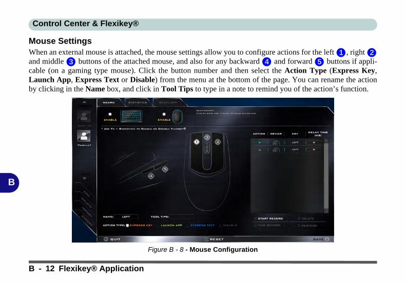
Control Center & Flexikey®
B
Mouse SettingsWhen an external mouse is attached, the mouse settings allow you to configure actions for the left , right and middle buttons of the attached mouse, and also for any backward and forward buttons if appli-cable (on a gaming type mouse). Click the button number and then select the Action Type (Express Key,Launch App, Express Text or Disable) from the menu at the bottom of the page. You can rename the actionby clicking in the Name box, and click in Tool Tips to type in a note to remind you of the action’s function.
Figure B - 8 - Mouse Configuration
1 23 4 5
B - 12 Flexikey® Application
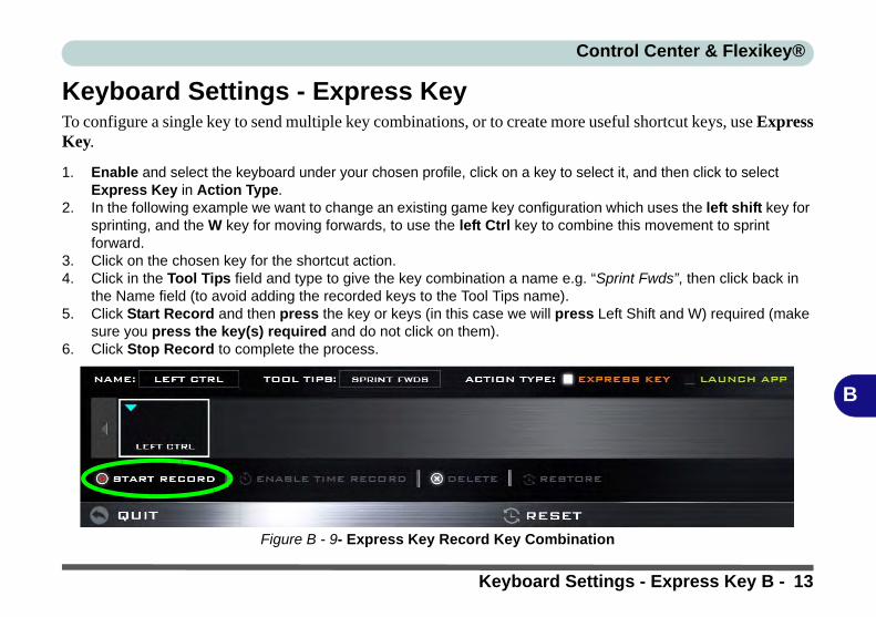
Control Center & Flexikey®
B
Keyboard Settings - Express KeyTo configure a single key to send multiple key combinations, or to create more useful shortcut keys, use ExpressKey.
1. Enable and select the keyboard under your chosen profile, click on a key to select it, and then click to select Express Key in Action Type.
2. In the following example we want to change an existing game key configuration which uses the left shift key for sprinting, and the W key for moving forwards, to use the left Ctrl key to combine this movement to sprint forward.
3. Click on the chosen key for the shortcut action.4. Click in the Tool Tips field and type to give the key combination a name e.g. “Sprint Fwds”, then click back in
the Name field (to avoid adding the recorded keys to the Tool Tips name).5. Click Start Record and then press the key or keys (in this case we will press Left Shift and W) required (make
sure you press the key(s) required and do not click on them).6. Click Stop Record to complete the process.
Figure B - 9- Express Key Record Key Combination
Keyboard Settings - Express Key B - 13

Control Center & Flexikey®
B
7. Click Save to save the settings within your chosen profile.8. If you want to remove any individual key click to select it, and then click Delete.9. If you want to clear all the settings click Restore to return to the default key setting.10. Any assigned Express Keys will appear in orange.
Figure B - 10 - Key Combination Set
Tool Tips
The Tool Tips field allows you to type a note to remind yourself of the function you have programmed the key for underany Profile.
B - 14 Keyboard Settings - Express Key

Control Center & Flexikey®
B
Enabling Time RecordIf you want to create a delay between key presses within the key combination, then you can use Time Recordfunction to do so.
1. Enable and select the keyboard under your chosen profile, click to select a key for the shortcut action, and then click to select Express Key in Action Type.
2. Click in the Tool Tips field and type to give the key combination a name, then click back in the Name field (to avoid adding the recorded keys to the Tool Tips name).
3. Click Start Record and then press the key or keys required in the sequence and time delay between key presses required (make sure you press the key(s) required and do not click on them).
4. Click Stop Record.5. Click to select a key in the sequence and click Enable Time Record , then click a
key to view the time delay.
Figure B - 11 - Enable Time Record
Keyboard Settings - Express Key B - 15

Control Center & Flexikey®
B
6. You can edit the delay between key presses by clicking in the Delay Time (MS) field and typing a new number for the delay between the key presses.
Figure B - 12 - Time Record Between Key Presses
7. Click to close the Time Record window.8. Click Save to save the settings within your chosen profile.9. If you want to remove any individual key click to select it, and then click Delete.10. If you want to clear all the settings click Restore to return to the default key setting.
B - 16 Keyboard Settings - Express Key

Control Center & Flexikey®
B
Keyboard Settings - Launch AppYou can configure keys to launch any application or program as follows:
1. Enable and select the keyboard under your chosen profile, click to select a key to launch the application, and then click to select Launch App in Action Type.
2. Click Browse... at the bottom right of the application window.
Figure B - 13 - Keyboard - Launch App (Browse to Executable File)
Keyboard Settings - Launch App B - 17

Control Center & Flexikey®
B
3. Navigate to the executable file of the application and click Open.4. The key will now be configured to open the selected application under your chosen Profile, and the key will
appear in green.
Figure B - 14 - Key Set to Launch App
5. If you want to remove any Launch App Key, select it and click on Restore.6. Click Save to save the settings within your chosen profile.
B - 18 Keyboard Settings - Launch App

Control Center & Flexikey®
B
Keyboard Settings - Express TextA single key can be set to send a string of text within any application using Express Text.
1. Enable and select the keyboard under your chosen profile, click to select a key, and then click to select Express Text in Action Type.
2. Click in Start key if required (the Start key is the key used to in your target program to open a text message), or you can leave it blank if you prefer.
3. Click in the Click to type field and type in your message.
Figure B - 15 - Keyboard - Express Text
Keyboard Settings - Express Text B - 19

Control Center & Flexikey®
B
4. Click in Send key if required (the Send key is the key used to in your target program to send a text message e.g the Enter key would be the most commonly used), or you can leave it blank if you prefer.
5. The key will now be configured to send the text message in the target program under your chosen Profile, and the key will appear in blue.
6. If you want to remove any Express Text key, select it and click on Restore.7. Click Save to save the settings within your chosen profile.
Copy & Paste Text
Note that some applications and games do not support copy and pasted text. Where this is the case, any text you may havecopy and pasted in to the “Type to Text” field may not be displayed within the application. In this case you will need to typethe text into the field instead.
B - 20 Keyboard Settings - Express Text

Control Center & Flexikey®
B
Keyboard Settings - DisableYou can use the program to disable any keys not required.
1. Enable and select the keyboard under your chosen profile, click to select a key to disable, and then click to select Disable in Action Type.
2. The key will now be disabled.3. If you want to enable the key again, select it and click on Restore.4. Click Save to save the settings within your chosen profile.5. The key will be disabled under your chosen Profile, and the key will appear in Gray.
Figure B - 16 - Keyboard - Disable
Keyboard Settings - Disable B - 21

Control Center & Flexikey®
B
Mouse Settings - Express KeyTo assign a mouse button click to send multiple key combinations (an external mouse must be attached), or tocreate more useful shortcut keys, use Express Key.
1. Enable and select the mouse under your chosen profile, click on a mouse button to select it, and then click to select Express Key in Action Type.
2. In the following example we will configure the central mouse wheel to combine the actions of left shift key for sprinting, and the W key for moving forwards in a game program.
3. Click on the central mouse wheel for the shortcut action.
Figure B - 17 - Mouse - Express Key Record Key Combination (Mouse)
B - 22 Mouse Settings - Express Key

Control Center & Flexikey®
B
4. Click in the Tool Tips field and type to give the key combination a name e.g. “Sprint Fwds”, then click back in the Name field (to avoid adding the recorded keys to the Tool Tips name).
5. Click Start Record and then press the key or keys (in this case we will press Left Shift and W) required (make sure you press the key(s) required and do not click on them).
6. Click Stop Record to complete the process.7. Click Save to save the settings within your chosen profile.8. If you want to remove any mouse setting click to select it, and then click Delete.9. If you want to clear all the settings click Restore to return to the default mouse setting.10. The mouse button for any assigned Express Keys will appear in orange.
Enabling Time Record for Mouse SettingsIf you want to create a delay between key presses within the mouse click combination, then you can use TimeRecord function to do so in the same manner as that used for keyboard settings (see “Enabling Time Record”on page B - 15).
Mouse Settings - Express Key B - 23
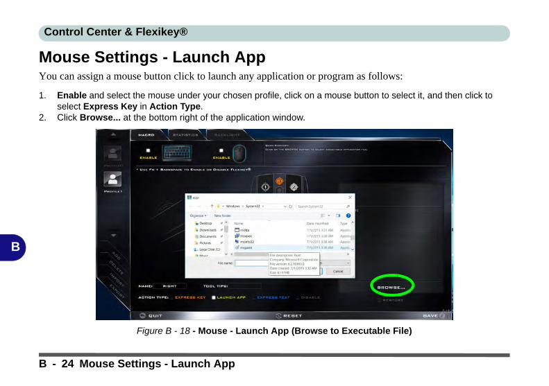
Control Center & Flexikey®
B
Mouse Settings - Launch AppYou can assign a mouse button click to launch any application or program as follows:
1. Enable and select the mouse under your chosen profile, click on a mouse button to select it, and then click to select Express Key in Action Type.
2. Click Browse... at the bottom right of the application window.
Figure B - 18 - Mouse - Launch App (Browse to Executable File)
B - 24 Mouse Settings - Launch App

Control Center & Flexikey®
B
3. Navigate to the executable file of the application and click Open.4. The mouse click will now be configured to open the selected application under your chosen Profile, and the
button will appear in green5. Click Save to save the settings within your chosen profile.
Figure B - 19 - Mouse Button Set to Launch App
Mouse Settings - Launch App B - 25
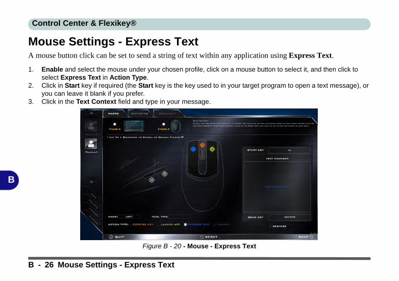
Control Center & Flexikey®
B
Mouse Settings - Express TextA mouse button click can be set to send a string of text within any application using Express Text.
1. Enable and select the mouse under your chosen profile, click on a mouse button to select it, and then click to select Express Text in Action Type.
2. Click in Start key if required (the Start key is the key used to in your target program to open a text message), or you can leave it blank if you prefer.
3. Click in the Text Context field and type in your message.
Figure B - 20 - Mouse - Express Text
B - 26 Mouse Settings - Express Text

Control Center & Flexikey®
B
4. Click in Send key if required (the Send key is the key used to in your target program to send a text message e.g the Enter key would be the most commonly used), or you can leave it blank if you prefer.
5. The mouse button click will now be configured to send the text message in the target program under your chosen Profile, and the button will appear in blue.
6. If you want to remove any Express Text mouse button, select it and click on Restore.7. Click Save to save the settings within your chosen profile.
Mouse Settings - Express Text B - 27

Control Center & Flexikey®
B
Mouse Settings - DisableYou can use the program to disable any mouse button clicks if not required.
1. Enable and select the mouse under your chosen profile, click on a mouse button to select it, and then click to select Disable in Action Type.
2. The button click will now be disabled.3. If you want to enable the button again, select it and click on Restore.4. Click Save to save the settings within your chosen profile.5. The button click will be disabled under your chosen Profile, and the key will appear in Gray.
Figure B - 21 - Mouse - Disable
B - 28 Mouse Settings - Disable

Control Center & Flexikey®
B
StatisticsThe Statistics tab allows you to record keys used in any application, and to disable any infrequently, or unused,keys to save any accidental incorrect key presses.
1. Click the Statistics Tab, and press Start Record to start recording the frequency of key presses for keys used.2. You can then go to the application you wish to use the profile for, and use the application as normal so that a
standard set of keys used may be recorded.3. Return to the Flexikey® application and press Stop Record to stop recording. 4. At the end of the recording process colors will represent the frequency of key presses, with red as the most
frequent through to lighter blue the less frequent (the color bar at the bottom of the screen displays the color code against the number of key presses).
5. Under Quick Disable click the color which corresponds to the keys you wish to disable.6. All disabled keys will then change to gray and will be disabled under this profile.
Figure B - 22 - Statistics
Statistics B - 29

Control Center & Flexikey®
B
B - 30
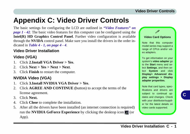
Video Driver Controls
C
Appendix C: Video Driver ControlsThe basic settings for configuring the LCD are outlined in “Video Features” onpage 1 - 42. The basic video features for this computer can be configured using theIntel(R) HD Graphics Control Panel. Further video configuration is availablethrough the NVIDA control panel. Make sure you install the drivers in the order in-dicated in Table 4 - 1, on page 4 - 4.
Video Driver Installation
Video (VGA)1. Click 2.Install VGA Driver > Yes.2. Click Next > Yes > Next > Next.3. Click Finish to restart the computer.
NVIDIA Video (VGA)1. Click 3.Install NVIDIA VGA Driver > Yes.2. Click AGREE AND CONTINUE (button) to accept the terms of the
license agreement.3. Click Next.4. Click Close to complete the installation.5. After all the drivers have been installed (an internet connection is required)
run the NVIDIA GeForce Experience by clicking the desktop icon (or App).
Video Card Options
Note that this computermodel series may support arange of CPUs and/or vid-eo adapters.
To get information on yoursystem’s video adapter goto the Start menu and se-lect Settings, and then se-lect System and clickDisplay> Advanced dis-play settings > Displayadapter properties.
Note that card types, spec-ifications and drivers aresubject to continual up-dates and changes. Checkwith your distributor/suppli-er for the latest details onvideo cards supported.
Video Driver Installation C - 1

Video Driver Controls
C
Microsoft Hybrid GraphicsMost notebook computers come with either a discrete or integrated graphics solu-tion.
Discrete graphics solutions feature a dedicated Graphics Processing Unit (GPU)which are capable of playing games, watching HD video or running GPU-based ap-plications. However computers with discrete graphics solutions tend to be heavy inpower consumption, and slightly larger in size in order to incorporate the dedicateddiscrete GPU.
Integrated graphics solutions usually feature memory sharing technology to helpsave power consumption and allow for longer battery life. However computers withintegrated graphics solutions will not usually run games, HD video or GPU-basedapplications without severe limitations.
Microsoft Hybrid Graphics is a seamless technology designed to get best perfor-mance from the graphics system while allowing longer battery life, without havingto manually change settings. Thus when an application is run that requires extra per-formance or quality, then the system will run the discrete GPU (dGPU); when thesystem does not require such enhanced performance it will let the integrated (iGPU)handle it.
C - 2 Microsoft Hybrid Graphics

Video Driver Controls
C
How the Technology worksWhen the system is powered up and is displaying just the desktop, the dGPU will bepowered off. In this case the system is running in the same way as a system withouta discrete graphics solution. However when an application that requires use of thedGPU is run (e.g, a game or HD Video), the dGPu is powered on and takes over theprocessing duties. If the program is closed, then the dGPU will be powered backdown again until required.
Customization
Options
Although Microsoft Hy-brid Graphics is com-pletely seamless to theuser, NVIDIA also allowcustomization optionswithin the control panel(see “CustomizationOptions” on page C -33).
Microsoft Hybrid Graphics C - 3
Video Driver Controls
C
Intel® Dynamic Video Memory TechnologyIntel® DVMT automatically and dynamically allocates as much system memory(RAM) as needed to the integrated video system (the video driver must be in-stalled). DVMT returns whatever memory is no longer needed to the operating sys-tem.
C - 4 Intel® Dynamic Video Memory Technology

Video Driver Controls
C
Configure Other Displays Using ProjectYou can configure attached displays from Project.
1. Attach your display to the appropriate port, and turn it on.2. Press the + P key combination.3. Click on any one of the options from the menu to select PC screen only,
Duplicate, Extend or Second screen only.4. You can also click Connect to a wireless display at the bottom of the Project
screen and follow the steps to connect to any wireless enabled display.
Figure C - 1Project
Configure Other Displays Using Project C - 5
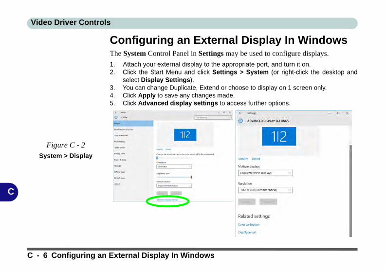
Video Driver Controls
C
Configuring an External Display In WindowsThe System Control Panel in Settings may be used to configure displays.
1. Attach your external display to the appropriate port, and turn it on.2. Click the Start Menu and click Settings > System (or right-click the desktop and
select Display Settings).3. You can change Duplicate, Extend or choose to display on 1 screen only.4. Click Apply to save any changes made.5. Click Advanced display settings to access further options.
Figure C - 2System > Display
C - 6 Configuring an External Display In Windows

Video Driver Controls
C
HDMI Audio ConfigurationHDMI (High-Definition Multimedia Interface) carries both audio and video signals.In some cases it will be necessary to go to the Sound control panel and manuallyconfigure the HDMI audio output as per the instructions below.
1. Go to the Sound control panel.2. Click Playback (tab)3. The playback device will be selected.4. You may need to select the audio device and click Set Default (button).5. Double-click the device to access the control panel tabs.
Volume Adjustment
The sound volume levelcan be clicking using thevolume control icon in the notification areaof the taskbar.
Figure C - 3Sound - HDMI
Device (set Default)
HDMI Audio Configuration C - 7

Video Driver Controls
C
6. Adjust the HDMI settings from the control panel tabs.7. Click OK to close the Sound control panel.
Figure C - 4HDMI Device
Properties
C - 8 HDMI Audio Configuration

Video Driver Controls
C
HDMI Notes• Connect a device with HDMI support to the HDMI-Out port BEFORE attempt-
ing to play audio/video sources through the device.• To play audio sources through your external display’s (TV or LCD) speakers
you will need to go to the audio configuration control panel on the display and configure the audio input accordingly (see your display device manual).
• Note that the Sound Blaster Cinema 3 SBX Pro Studio audio effects do not apply to audio generated through an HDMI connection.
HDMI Video Configuration1. Connect an HDMI cable from the HDMI-Out port to your external display.2. Configure your external display as per the instructions in “Attaching Other
Displays” on page C - 27.3. Set up your external display (TV or LCD) for HDMI input (see your display device
manual).4. You can now play video/audio sources through your external display.
Other Applications
If you are using a thirdparty application to playDVDs etc. from any at-tached DVD device,you will need to consultthe application’s docu-mentation to see theappropriate audio con-figuration (the applica-tion must support digitalto analog translation).
HDMI Audio Configuration C - 9

Video Driver Controls
C
Wireless DisplayWireless Display uses your Wireless LAN module/WLAN Bluetooth Combo mod-ule (you need to make sure that your video adapter/display device is compatiblewith your particular WLAN/Combo module) in conjunction with a compatiblevideo adapter/display device (purchased separately) to allow you to display thecontents of the notebook display on another display (e.g. HDTV), without the needto have cables stretching across a room.
You can use the wireless display to play games, browse the internet, display videosor photo slide shows on your TV/external display without using HDMI or A/V ca-bles.
Before configuring Wireless Display you will need to set up your compatibleadapter with your display/speakers. Connect the adapter using an HDMI or A/V ca-ble and turn on the display (or in the case of speakers connect them to the wirelessspeaker adapter with the cables provided with the adapter), and then set the displayto the appropriate input channel (see the documentation supplied with your compat-ible adapter/display for full details).
Note that no driver or application is required for wireless display in Windows 10.
Compatible Adapters
For a list of compatibleadapters check the vid-eo adapter/display de-vice documentation, orwith your distributor/supplier.
C - 10 HDMI Audio Configuration

Video Driver Controls
C
Wireless Display Configuration1. Note that no driver or application is required for wireless display in Windows 10.2. Press the + P key combination.3. Click Connect to a wireless display at the bottom of the Project screen and
follow the steps to connect to any wireless enabled display.
4. The system will then search for compatible display devices (this may take up to60 seconds so allow time for this to complete).
5. Double-click any detected display device in the list.
Figure C - 5Add a Wireless
Display
Wireless Display Configuration C - 11

Video Driver Controls
C
6. You may then need to input a pin number for the device to which you are connecting and click Next.
7. The display will then connect (for specific settings for your display see the documentation supplied with your compatible adapter/display for full details).
8. Go to the Project menu and click Disconnect to temporarily disconnect from the wireless display.
9. To permanently disconnect from the display (you will need to go back through the connection process again) you can select it in Devices and click Remove Device > Yes.
C - 12 Wireless Display Configuration

Video Driver Controls
C
Intel® HD Graphics Control PanelAdvanced video configuration options are provided by the Intel® HD Control Pan-el. To access the control panel see below and overleaf:
1. Right-click the Desktop and select Intel(R) Graphics Settings from the menu.
OR2. Click the icon in the notification area of the Desktop taskbar and select Intel(R)
Graphics Settings from the menu.
Figure C - 6Right-Click Desktop
(Intel Graphics
Settings)
Figure C - 7Taskbar Notification
Area Icon Menu
Intel® HD Graphics Control Panel C - 13

Video Driver Controls
C
OR3. Double-click the Intel(R) HD Graphics control panel in the Windows Control
Panel.
Figure C - 8 Control Panel
Intel® Graphics
Settings
C - 14 Intel® HD Graphics Control Panel

Video Driver Controls
C
You may make changes to any of the graphics properties by clicking the appropriatemenu panel and adjusting the settings from the menus.
Home
Click the Home button toreturn to the main menuscreen in any of the sub-menu screens.
Figure C - 9Intel® HD Graphics
Control Panel
Intel® HD Graphics Control Panel C - 15

Video Driver Controls
C
DisplayClick either Display Settings or Color Settings to make display adjustments, in-cluding configuration for any attached external displays.
Multiple Display
At least one other dis-play must be attached inorder to view multipledisplay selection op-tions.
Figure C - 10Intel® HD Graphics
Control Panel
Display
C - 16 Intel® HD Graphics Control Panel

Video Driver Controls
C
Click the Display menu at the top of the screen to display the sub-menus. The Mul-tiple Displays menu allows you to configure the display mode of any attached dis-plays (see “Attaching Other Displays” on page C - 27). Click Apply to save anychanges made.
Multiple Display
At least one other dis-play must be attached inorder to view multipledisplay selection op-tions.
Audio Settings
Any attached active dis-plays must have audiocapacity to allow audioconfiguration.
Figure C - 11Intel® HD Graphics
Control Panel
Display - Multiple
Displays
Intel® HD Graphics Control Panel C - 17

Video Driver Controls
C
The Custom Resolutions sub-menu allows you to adjust the display (or any at-tached display) to any width, height, refresh rate, color depth and underscan percent-age of your choice. Note that incorrect settings can cause system instability and evenpossible component damage, so this is adjusted at your own risk.
Figure C - 12Intel® HD Graphics
Control Panel
Display Settings -
Custom
Resolutions
C - 18 Intel® HD Graphics Control Panel

Video Driver Controls
C
3DThis menu allows you to choose how 3D images are displayed. Performance givesthe smoothest motion of images, Quality displays the most detail, Balanced Modeprovides better computer performance with good quality and Custom allows you toconfigure the Anisotropic Filtering and Vertical Sync and features to your prefer-ences. Click Apply to save changes.
Figure C - 13Intel® HD Graphics
Control Panel 3D
Intel® HD Graphics Control Panel C - 19
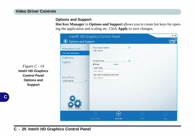
Video Driver Controls
C
Options and SupportHot Key Manager in Options and Support allows you to create hot keys for open-ing the application and scaling etc. Click Apply to save changes.
Figure C - 14Intel® HD Graphics
Control Panel
Options and
Support
C - 20 Intel® HD Graphics Control Panel

Video Driver Controls
C
Click the Options menu at the top of the screen to display the sub-menus. The In-formation Center provides details on System Information, the Built-In Displayand any attached displays.
Preferences
Go to the Preferencessub-menu in Options toconfigure the preferencesfor the Intel® HD GraphicsControl Panel.
Make sure you click En-able under Tray Icon todisplay the Intel® HDGraphics Control Panelicon in the notification areaof the taskbar (as below).
Figure C - 15Intel® HD Graphics
Control Panel
Options -
Information Center
Intel® HD Graphics Control Panel C - 21

Video Driver Controls
C
VideoThe Video menu allows you to brighten or darken movies, or to switch to vivid col-ors. The Preview image will display a sample image using the current settings. Youcan Save Profile and name the Profile to recall the settings at any time. Click Applyto save changes (select Color Enhancement or Image Enhancement from themenu).
Figure C - 16Intel® HD Graphics
Control Panel -
Video
(Color
Enhancement)
C - 22 Intel® HD Graphics Control Panel

Video Driver Controls
C
Click the Video menu at the top of the screen to display the sub-menus.The ImageEnhancement menu allows you to adjust the Sharpness, Skin Tone Enhance-ment, Noise Reduction, Contrast Enhancement and Film Mode Detection. ClickApply to save changes.
Figure C - 17Intel® HD Graphics
Control Panel - Video
(Image
Enhancement Basic)
Intel® HD Graphics Control Panel C - 23

Video Driver Controls
C
PowerThe battery life can be extended through dynamic control of the frame rate if Ex-tended Battery Life for Gaming is enabled. Settings can be selected for when thesystem is powered by battery or is plugged in.
Figure C - 18Intel® HD Graphics
Control Panel -
Power
C - 24 Intel® HD Graphics Control Panel

Video Driver Controls
C
ProfilesYou can select one of the preset profiles (Brighten Video, Darken Video and En-hance Video Colors) from the menu on the left. Alternatively you can go throughthe menus to make adjustments to your preferences for Display, Color, Video, Op-tions and Support and Power (tick any boxes for the settings required), and thenSave the settings to a profile (which may be imported or exported).
Figure C - 19Intel® HD Graphics
Control Panel -
Profiles
Intel® HD Graphics Control Panel C - 25

Video Driver Controls
C
Display Devices & OptionsNote that you can use external displays connected to the HDMI-Out port and/or ex-ternal monitor port and Mini Display (1.2) port. See your display device manual tosee which formats are supported.
Display Mode Description
Single DisplayOne of the connected displays is used as the display device (PC screen only or Second screen only).
Clone/DuplicateBoth connected displays output the same view and may be configured independently
Extended / Extend
Both connected displays are treated as separate devices, and act as a virtual desktop
CollageA number of connected displays are combined into a single unified higher resolution for larger screen sizes
Hybrid
A number of connected displays are combined and can be configured in a combination of Clone and Extended modes
4K2K Videos on 4K2K
External Displays
Note you may experi-ence some video lagwhen playing 4K2K vid-eos on an attached4K2K external display.
Table C - 1Display Modes
Attaching Displays
When you first attachan external displayyou may find that thedesktop does not oc-cupy the full screenarea. Use either thedisplay’s auto adjust/configure controls, orthe Intel(R) HDGraphics ControlPanel to configurethe full screen dis-play.
C - 26 Display Devices & Options

Video Driver Controls
C
Attaching Other DisplaysTo Clone Displays:1. Attach your external display to the appropriate port, and turn it on.2. Go to the Intel(R) HD Graphics Control Panel control panel and click Display >
Multiple Displays (sub-menu).3. Click Clone from the Select Display Mode menu.4. Click Apply, and OK to confirm the settings change.5. Select the displays from the Select One or More Active Displays menu.
Multiple Display
At least one other dis-play must be attached inorder to view MultipleDisplay selection op-tions.
Figure C - 20 Display > Multiple
Displays (Clone)
Attaching Other Displays C - 27

Video Driver Controls
C
To Enable Extended Mode:1. Attach your external display to the appropriate port, and turn it on.2. Go to the Intel(R) HD Graphics Control Panel control panel and click Display >
Multiple Displays (sub-menu).3. Click Extended from the Select Display Mode menu.4. Click Apply, and OK to confirm the settings change.
Display Settings
Extended Desktop
You can have differentColors, Screen Areaand Monitor RefreshRates for each displaydevice provided yourmonitor can supportthem.
You can drag the moni-tor icons to match thephysical layout of yourdisplays. Icons and pro-grams may also bedragged between thedisplays.
Figure C - 21
Display > Multiple
Displays (Extended)Click the appropriate monitor icon and drag it to match the physical arrangement you wishto use (e.g. the secondary display may be extended left/right/above/below the primary dis-play).
C - 28 Attaching Other Displays

Video Driver Controls
C
To Enable Collage Mode:1. Attach your external display to the appropriate port, and turn it on.2. Go to the Intel(R) HD Graphics Control Panel control panel and click Display >
Multiple Displays (sub-menu).3. Click Collage from the Select Multiple Display Mode menu.4. Click Enable Collage and click On.5. Click Vertical or Horizontal to arrange and displays as required.6. Click Apply, and OK to confirm the settings change.
Collage Mode
Collage mode is used tocombine a number ofdisplays into a singleunified higher resolutionfor larger screen sizes,.
Figure C - 22
Display > Multiple
Displays (Collage)
Attaching Other Displays C - 29

Video Driver Controls
C
NVIDIA Control PanelMore advanced video configuration options are provided in the NVIDIA ControlPanel tab.
1. Go to the Control Panel.2. Double-click NVIDIA Control Panel (click to view the control panel in either Large
icons or Small icons if you are in Category view).
NVIDIA Control
Panel
To access the Ge-Force..... control panelfrom the desktop; right-click the desktop, thenclick NVIDIA ControlPanel.
Figure C - 23NVIDIA Control
Panel
C - 30 NVIDIA Control Panel
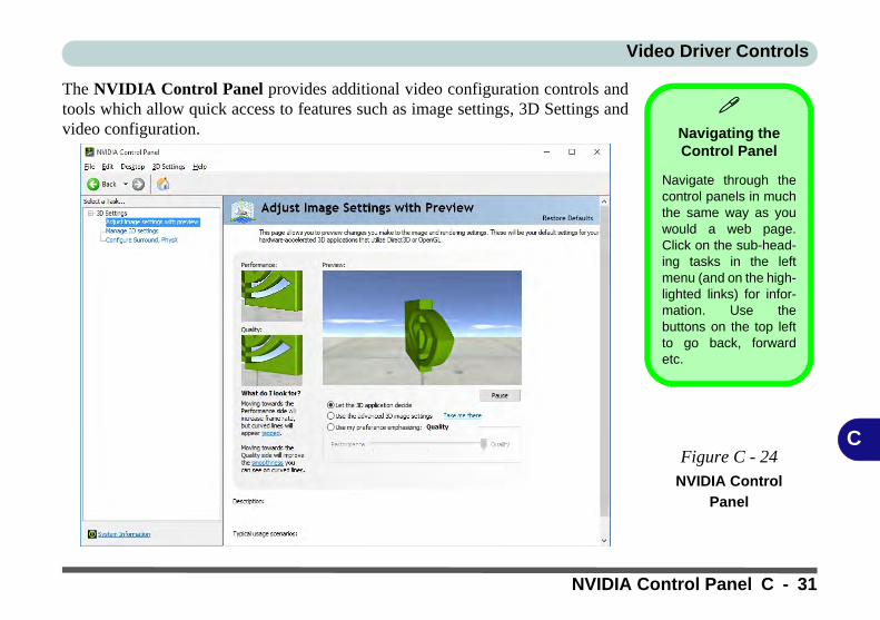
Video Driver Controls
C
The NVIDIA Control Panel provides additional video configuration controls andtools which allow quick access to features such as image settings, 3D Settings andvideo configuration.
Navigating the Control Panel
Navigate through thecontrol panels in muchthe same way as youwould a web page.Click on the sub-head-ing tasks in the leftmenu (and on the high-lighted links) for infor-mation. Use thebuttons on the top leftto go back, forwardetc.
Figure C - 24NVIDIA Control
Panel
NVIDIA Control Panel C - 31

Video Driver Controls
C
The Help menus provide index and search features, and direct links to the NVIDIAwebsite etc.
Figure C - 25Help Menu
C - 32 NVIDIA Control Panel

Video Driver Controls
C
Customization OptionsOne of the most important aspects of hybrid technology is that it will switch betweenthe integrated GPU and discrete GPU seamlessly and automatically, and does not re-quire any input from the user. However customization options are offered for userswho prefer to set their own parameters for GPU usage.
Context MenuOne of the quickest ways to choose which GPU to use for a particular application isby using the “Run with graphics processor” in the context menu.
1. Go to the NVIDIA Control Panel.2. Click Desktop from the top menu and select Add “Run with graphics
processor” to Context Menu (it should have a check alongside it).
Display GPU Activity Icon
Click to enable Dis-play GPU ActivityIcon in the Notifica-tion Area to quicklyaccess the GPU Activ-ity monitor from thetaskbar.
Figure C - 26NVIDIA Control
Panel - View
Customization Options C - 33

Video Driver Controls
C
3. Close the NVIDIA Control Panel.4. Find the executable file icon of the application you want to run.5. Right-click the icon and select Run with graphics processor from the context
menu.6. Select either High-performance NVIDIA processor (dGPU) or Integrated
graphics (iGPU) to run the program with the selected GPU.
iGPU or dGPU
Note the NVIDIA con-trol panel refers toHigh-performanceNVIDIA processor(which is the discreteGPU) and Integratedgraphics (which is theintegrated GPU).
Figure C - 27Context Menu with
Run with graphics
processorRight-click the application executable file
C - 34 Customization Options

Video Driver Controls
C
Global SettingsGlobal settings allows you to set the preferred graphics processor for overall use.Ideally this would be the iGPU for battery life, but this can be set to the dGPU if pre-ferred.
1. Go to the NVIDIA Control Panel.2. Click Manage 3D Settings (3D Settings) and select Global Settings (tab).3. Select either Integrated graphics (iGPU) or High performance NVIDIA
Processor (dGPU) from the drop-down menu.4. Click the Setting menu items to select any options required.5. Click Apply to save the settings.
Customization
Options
Although hybrid tech-nology is completelyseamless to the user,there are customiza-tion options within thecontrol panel (seepage C - 32).
Figure C - 28Global Settings
Customization Options C - 35

Video Driver Controls
C
Program SettingsProgram settings allows you to make specific adjustments for installed applications.
1. Go to the NVIDIA Control Panel.2. Click Manage 3D Settings (3D Settings) and select Program Settings (tab).3. Select a program to customize from the drop-down menu, or click Add to add
any program that does not appear in the menu.4. Select the preferred graphics processor for the program from the drop-down
menu.5. Click the Setting menu items to select any options required.6. Click Apply to save the settings.
Figure C - 29Program Settings
C - 36 Customization Options

Video Driver Controls
C
Configure Surround, PhysX®
NVIDIA® PhysX® is a physics engine that can use the GPU to accelerate game and3D application performance. You can select the GeForce video card or CPU as aPhysX® processor, or configure the computer to auto-select a PhysX® processor(recommended default setting).
1. Go to the NVIDIA Control Panel.2. Click Configure Surround, PhysX.3. Click to select a processor from the menu (PhysX Settings); Auto-select
(recommended) is the default setting.4. Click Apply to save the settings.
Figure C - 30Configure
Surround, PhysX
Configure Surround, PhysX® C - 37

Video Driver Controls
C
NVIDIA GeForce ExperienceIf you have a working internet connection (and you will need remain connectedto the internet to run NVIDIA GeForce Experience) you can click the NVIDIAGeForce Experience desktop icon (or App) to run the application. This will op-timize your gaming settings for your NVIDIA GPU by downloading the latest set-tings from the NVIDIA cloud data center.
You may need to create an NVIDIA account to log-in to the system (alternativelyyou may be able to use your Facebook or Google account to log-in).
After logging in to the system you can click through any on-screen instructions toupdate your settings and check for installed games etc.
By running the NVIDIA GeForce Experience you will be able to download the lat-est drivers to insure compatibility with games, power saving features and variousother enhancements for your NVIDIA GPU (these features are subject to change andupdate so check with the NVIDIA website for the latest information).
Note that to enable BatteryBoost you must be connected to the internet.
NVIDIA GeForce
ExperienceVersion
Note that the NVIDIAGeForce Experienceapplication is subjectto constant, change,update and revision,so make sure you con-nect and update regu-larly in order to get thelatest settings and in-formation.
C - 38 NVIDIA GeForce Experience

Specifications
D
Appendix D: Specifications
Latest Specification Information
The specifications listed in this Appendix are correct at the time of going to press. Certain items (particularly processor types/speeds and CD/DVD device types) may be changed, updated or delayed due to the manufacturer's release schedule. Checkwith your distributor/supplier for details.
Note that this computer model series may support a range of CPUs and/or video adapters.
To find out which CPU is installed on your system go to the Start menu and select Settings, and then select System andclick About. This will also provide information on the amount of Installed RAM etc.
To get information on your system’s video adapter go to the Start menu and select Settings, and then select System andclick Display> Advanced display settings > Display adapter properties.
Specifications D - 1

Specifications
D
Core Logic
Mobile Intel® HM175 Express Chipset
Display
For Models A & B:15.6" (39.62cm), 3.2 mm, FHD (1920 * 1080) / UHD (3840 * 2160), 16:9 Backlit Panel
For Model C:17.3" (43.94cm), 4.0 mm, FHD (1920 * 1080) / UHD (3840 * 2160),16:9 Backlit Panel
Memory
Dual Channel DDR4
Two 260 Pin SO-DIMM Sockets Supporting DDR4 2400 MHz Memory Modules (real operational frequency depends on the FSB of the processor)
Memory Expandable up to 32GB (maximum), Compatible with 4GB/8GB/16GB Modules
Storage
One Changeable 2.5" 7mm(h) Hard Disk Drives (HDD) / Solid State Drives (SSD) with SATA Interface
One M.2 2280 SSDs with SATA Interface (Factory Option) OROne M.2 2280 SSD with PCIe Gen 3 x4 Interface (Factory Option)
BIOS
One 64Mb SPI Flash ROM AMI BIOS
SO-DIMM Memory Types
All SO-DIMM memory modules installed in thesystem should be identical (the same size andbrand) in order to prevent unexpected systembehavior.
Don’t mix SO-DIMM memory module sizesand brands in order to prevent system prob-lems.
Audio
High Definition AudioBuilt-In Array Microphone2 Built-In SpeakersSound Blaster™ Cinema 3
Keyboard & Pointing Device
Full Size White LED Illuminated Keyboard with Numeric Pad (Factory Option)
Full Size Colored RGB LED Illuminated Keyboard with Numeric Pad (Factory Option)
Built-In TouchPad with Microsoft Multi Gesture & Scrolling Functionality
Indicators
LED Indicators - Power/Suspend, Battery, HDD, Camera
Interface
One USB 2.0 PortTwo USB 3.0 (USB 3.1 Gen 1) Ports (Type-A)One USB 3.0 (USB 3.1 Gen 1) Port (Type-C)
See over
D - 2 Specifications

Specifications
D
===============================One USB 3.1 (Gen 2 - Type A) Port & One USB 3.1 (Gen 2 - Type C*) Port (Factory Option shared with USB 3.0 ports) - 2 * USB 3.1 Gen 2 Ports with 10Gb Shared Bandwidth===============================*Note: The maximum amount of current supplied by USB Type-C ports is 500 mA for USB2.0/900 mA for USB 3.1===============================2 * Mini DisplayPorts 1.2One HDMI™ (High-Definition Multimedia Interface) Out Port (with HDCP)One Headphone/Speaker-Out JackOne Microphone-In JackOne RJ-45 LAN JackOne DC-In Jack
Card Reader
Embedded Multi-In-1 Push-Push Card Reader - MMC / RSMMC- SD / Mini SD / SDHC / SDXC
Card Reader Note: Some of the cards require PC adapters that are usually supplied with the cards.
Slots
Two or Three M.2 Slots:=======================================Slot 1: for M.2 2230 WLAN Combo Module Card with PCIe & USB Interfaces (A Key)
Slot 2: for M.2 2280 SSD Card with SATA/ PCIe Gen 3 x4 Interface (M Key)
For Models A & B Only:Slot 3: for LTE or UTMS/HSPA+ M.2 3042 3G or 4G Module Card with USB Interface (B Key) - (Factory Option)
Communication
Built-In 10/100/1000Mb Base-TX Ethernet LAN
Intel® Dual Band Wireless-AC 8265(2*2 802.11 a/c) M.2 WLAN + BluetoothCombo M.2 2230 Module (Factory Option)
Intel® Dual Band Wireless-AC 3168 (1*1802.11 ac) WLAN + Bluetooth Combo M.22230 Module (Factory Option)===============================For Model C:2.0M FHD PC Video Camera Module (Factory Option)
For Models A & B:1.0M HD PC Video Camera Module2.0M FHD PC Video Camera Module (Factory Option)===============================For Models A & B Only:3G UTMS/HSPA+ M.2 3042 Card Module (Factory Option)4G LTE M.2 3042 Card Module (FactoryOption)
Operating System
Windows® 10 (64-bit)
Features (Depends on Model Type)
Painted StyleShipping ModeFlexichargerAll-AlloyMicrosoft Cortana with Voice TechnologyIntel® Optane™
Security
Security (Kensington® Type) Lock SlotBIOS PasswordIntel® PTT for Systems without TPM
Specifications D - 3
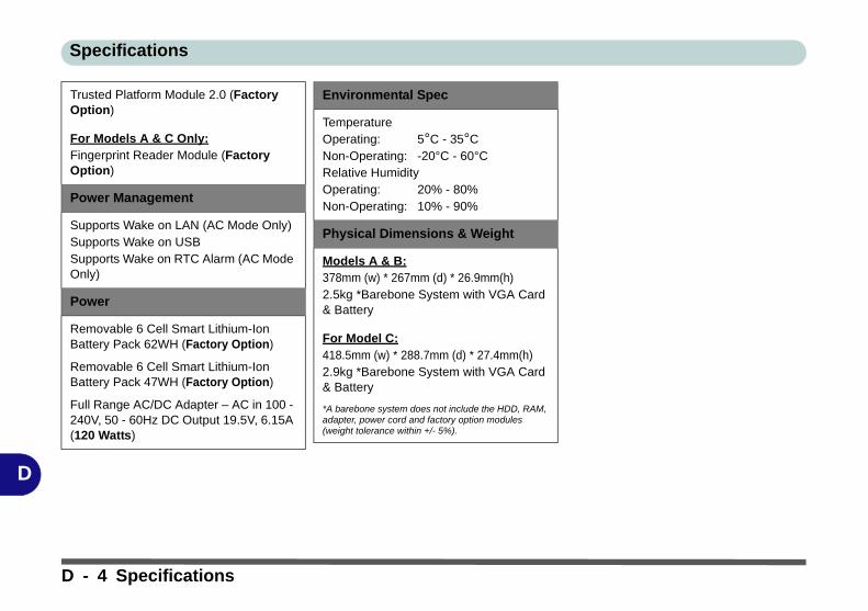
Specifications
D
Trusted Platform Module 2.0 (Factory Option)
For Models A & C Only:Fingerprint Reader Module (Factory Option)
Power Management
Supports Wake on LAN (AC Mode Only)Supports Wake on USBSupports Wake on RTC Alarm (AC Mode Only)
Power
Removable 6 Cell Smart Lithium-Ion Battery Pack 62WH (Factory Option)
Removable 6 Cell Smart Lithium-Ion Battery Pack 47WH (Factory Option)
Full Range AC/DC Adapter – AC in 100 - 240V, 50 - 60Hz DC Output 19.5V, 6.15A (120 Watts)
Environmental Spec
TemperatureOperating: 5°C - 35°CNon-Operating: -20°C - 60°CRelative HumidityOperating: 20% - 80%Non-Operating: 10% - 90%
Physical Dimensions & Weight
Models A & B:378mm (w) * 267mm (d) * 26.9mm(h)2.5kg *Barebone System with VGA Card & Battery
For Model C:418.5mm (w) * 288.7mm (d) * 27.4mm(h)2.9kg *Barebone System with VGA Card & Battery
*A barebone system does not include the HDD, RAM, adapter, power cord and factory option modules (weight tolerance within +/- 5%).
D - 4 Specifications