v82-1,65 mw gb exchange compl. us vers
TRANSCRIPT
Item no.: 1001816.R3 Date 2007-07-23 Issued by: Technology Class: II Type: Work Instruction Page 1 of 62
Replacement of Gearbox with Fixture, V82 – 1.65MW
Vestas Wind Systems A/S · Alsvej 21 · 8900 Randers · Denmark · www.vestas.com
Replacement of Gearbox with Fixture, V82 – 1.65 MW
Prepared by: Approved by: Reference/Drawing Work-place Business Unit TKB FSA See the section
Required Documentation
Service Technology
History of this Document
Rev. no.: Date: Description of changes 1 2006-10-24 First edition 2 2007-01-12 Extra history and table of contents removed
Page 58: Benzene changed to Benzine 3 2007-07-23 Update of Item no for Safety Railing in tools list
Item no.: 1001816.R3 Date 2007-07-23 Issued by: Technology Class: II Type: Work Instruction Page 2 of 62
Replacement of Gearbox with Fixture, V82 – 1.65 MW Table of Contents
Vestas Wind Systems A/S · Alsvej 21 · 8900 Randers · Denmark · www.vestas.com
Table of Contents
1 Safety.......................................................................................................................................................3 2 Educational Requirements of Technician............................................................................................3 3 Required Documentation.......................................................................................................................3 4 Purpose ...................................................................................................................................................3 5 Risk Assessment....................................................................................................................................3 6 Note..........................................................................................................................................................5 7 Tools ........................................................................................................................................................5 8 Spare Parts..............................................................................................................................................8 9 Weights....................................................................................................................................................8 10 Estimated Time Use ...............................................................................................................................8 11 Procedure................................................................................................................................................9 11.1 Preparing of rotor lock ..............................................................................................................................9 11.2 Preparing of fixture ...................................................................................................................................9 11.3 Lifting equipment for the Gearbox and adjustment to the right angle ...................................................14 11.4 Various preparing in the nacelle............................................................................................................15 11.5 Stripping of gearbox ...............................................................................................................................23 11.6 Slip ring unit and rotating union..............................................................................................................29 11.7 Rotor lock ...............................................................................................................................................31 11.8 Centa Link Coupling ...............................................................................................................................36 11.9 Moving the generator .............................................................................................................................39 11.10 Preparing in the hub ...............................................................................................................................39 11.11 Hoses to the coolers on the roof ............................................................................................................42 11.12 Cables and wires....................................................................................................................................44 11.13 Shrink disc ..............................................................................................................................................45 11.14 Torque arms ...........................................................................................................................................48 11.15 Nacelle cover..........................................................................................................................................49 11.16 Mounting the main shaft fixture ..............................................................................................................53 11.17 Preparing the new gearbox ....................................................................................................................58 11.18 Switching gearboxes ..............................................................................................................................61 11.19 Installing the nacelle cover .....................................................................................................................62 11.20 Tightening the shrink disc.......................................................................................................................62 12 Reinstalling the nacelle and hub components..................................................................................62 12.1 Dismounting the rotor lock......................................................................................................................62 13 Alignment of gearbox and generator .................................................................................................62 14 Preparation of the old gearbox ...........................................................................................................62 15 Check points.........................................................................................................................................62 16 Start up..................................................................................................................................................62

Item no.: 1001816.R3 Date 2007-07-23 Issued by: Technology Class: II Type: Work Instruction Page 3 of 62
Replacement of Gearbox with Fixture, V82 – 1.65 MW Safety
Vestas Wind Systems A/S · Alsvej 21 · 8900 Randers · Denmark · www.vestas.com
1 Safety
Vestas safety rules must be followed. See the Health and Safety Manual:
1000711. See also Risk Assessment.
Maximum wind speed when using an external crane: 10m/s.
Maximum wind speed at alignment of the generator: 8m/s.
Wear protective glasses, hearing protector, hand protection (heat resistant gloves), safety helmet and safety shoes.
2 Educational Requirements of Technician
It is preferred to have at least one service technician with knowledge of gearbox replacement in this actual turbine type. At least 4 service technicians are required to do the gearbox replacement.
3 Required Documentation
1000711 Health and Safety Manual
5001097 Installation and Service Data
Service Manual:
1001818: Check List for Replacement of gearbox
Supplier drawing of Centa Link Coupling
4 Purpose
To replace a damaged gearbox on site.
5 Risk Assessment
Risk of falling to the ground from the nacelle
Danger to life due to the risk of falling out of the nacelle while working with the upper nacelle cover / roof dismantled.
Never work without being hooked or without a safety rail.
Make sure to be hooked onto two safe hooking points with two tackle ropes.

Item no.: 1001816.R3 Date 2007-07-23 Issued by: Technology Class: II Type: Work Instruction Page 4 of 62
Replacement of Gearbox with Fixture, V82 – 1.65 MW Risk Assessment
Vestas Wind Systems A/S · Alsvej 21 · 8900 Randers · Denmark · www.vestas.com
Crushing by falling load
Danger to life due to a falling load if e.g. a lifting chain brakes.
Never stand under a suspended load.
Use only lifting equipment designed for the task. If replacing spare parts for lifting equipment, use only original parts authorised by Vestas.
Always wear safety helmets with chain straps when the overhead crane is in operation.
Slipping and falling
Risk of person injury due to slipping and falling in the nacelle, e.g. stepping in spilled oil.
Do not slip or fall in the nacelle.
Make sure to wipe away spilled oil, use rags to suck up dripping oil or cooling water.
Electric shock
Risk of death or severe injury when touching wires with power.
Do not touch wires unless you are sure that the power supply is off.
Switch off power and check with a voltmeter that there is no power supply to the wires.
Risk of fingers or other body parts getting caught or crushed
Risk of getting fingers or other body parts caught or crushed when handling the gearbox or other parts.
Be careful when working with gearboxes or other parts.
Hearing damages
Risk of hearing damages when using an electric impact wrench or similar tools.
Use hearing protector when working with very noisy tools.
Item no.: 1001816.R3 Date 2007-07-23 Issued by: Technology Class: II Type: Work Instruction Page 5 of 62
Replacement of Gearbox with Fixture, V82 – 1.65 MW Note
Vestas Wind Systems A/S · Alsvej 21 · 8900 Randers · Denmark · www.vestas.com
6 Note
Before starting the job, read this work instruction carefully and prepare all the things you can do in advance, like packing/ordering the necessary tools and spare parts
This instruction is on the basis of a V82-1.65MW turbine. For NM64/NM72/NM82 turbines there are some differences.
It is recommended that the rotor is not locked for more than 48 hours; otherwise there is a risk of stand still marks on the main bearing.
It is recommended to use a safety railing as described in this instruction. It is however allowed to carry out the work without safety railing if the technicians in the open nacelle are properly hooked onto approved anchor points.
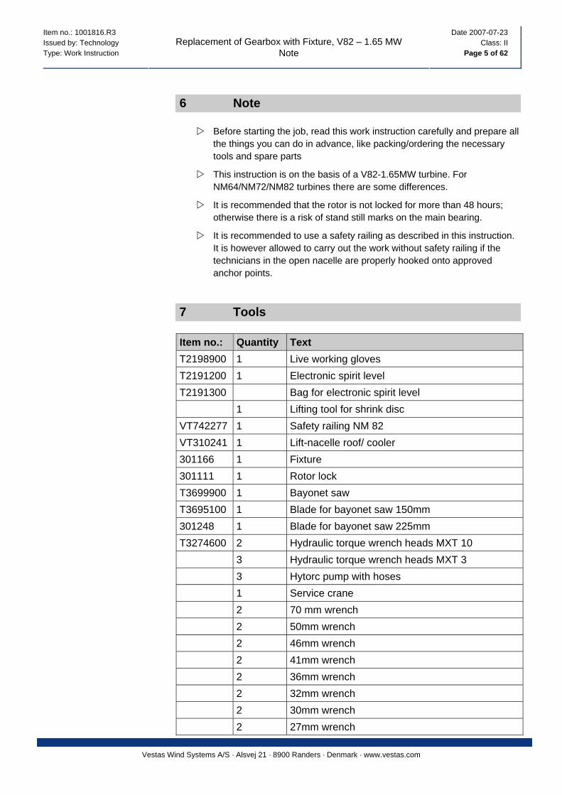
7 Tools
Item no.: Quantity Text T2198900 1 Live working gloves T2191200 1 Electronic spirit level T2191300 Bag for electronic spirit level 1 Lifting tool for shrink disc VT742277 1 Safety railing NM 82 VT310241 1 Lift-nacelle roof/ cooler 301166 1 Fixture 301111 1 Rotor lock T3699900 1 Bayonet saw T3695100 1 Blade for bayonet saw 150mm 301248 1 Blade for bayonet saw 225mm T3274600 2 Hydraulic torque wrench heads MXT 10 3 Hydraulic torque wrench heads MXT 3 3 Hytorc pump with hoses 1 Service crane 2 70 mm wrench 2 50mm wrench 2 46mm wrench 2 41mm wrench 2 36mm wrench 2 32mm wrench 2 30mm wrench 2 27mm wrench

Item no.: 1001816.R3 Date 2007-07-23 Issued by: Technology Class: II Type: Work Instruction Page 6 of 62
Replacement of Gearbox with Fixture, V82 – 1.65 MW Tools
Vestas Wind Systems A/S · Alsvej 21 · 8900 Randers · Denmark · www.vestas.com
Item no.: Quantity Text 2 24mm wrench 2 22mm wrench 4 19mm wrench 4 17mm wrench 4 13mm wrench 4 10mm wrench T2092400 2 8” adjustable wrench T2092600 2 12” adjustable wrench T2092800 2 18” adjustable s wrench 2 Medium multigrips 2 Large multigrips 4 90mm short, ring impact wrench T3275800 2 90mm impact socket1 ½” T3515800 2 50mm impact socket 1 ½” T3689200 2 55mm impact socket 1 ½” 2 55mm 1” short impact socket 2 50mm 1” short impact socket 2 46mm 1” short impact socket 2 41mm 1” short impact socket 2 41mm 1” long impact socket 2 55mm 3/4 ” short impact socket 2 50 3/4 ” short impact socket 2 46 3/4 ” short impact socket 2 41 3/4 ” short impact socket 2 36 3/4 ” short impact socket 2 32 3/4 ” short impact socket 2 30 3/4 ” short impact socket 2 41mm ¾” long impact socket 2 6mm ½” , 8mm ½” allen sockets 2 22, 27, 30mm 3/4” impact allen sockets 4 10, 13, 17, 19, 22, 24mm ½” sockets T2173000 1 ¾” torque wrench up to 140-760 Nm T2175100 1 ½” torque wrench up to 75-400 Nm 1 30mm ring spanner for ½” torque wrench 300350 2 ½” electric impact , cordless if possible 2 ¾” electrical impact wrench 8 Pairs of sidecutters 4 Small flat and Phillips screwdrivers
Item no.: 1001816.R3 Date 2007-07-23 Issued by: Technology Class: II Type: Work Instruction Page 7 of 62
Replacement of Gearbox with Fixture, V82 – 1.65 MW Tools
Vestas Wind Systems A/S · Alsvej 21 · 8900 Randers · Denmark · www.vestas.com
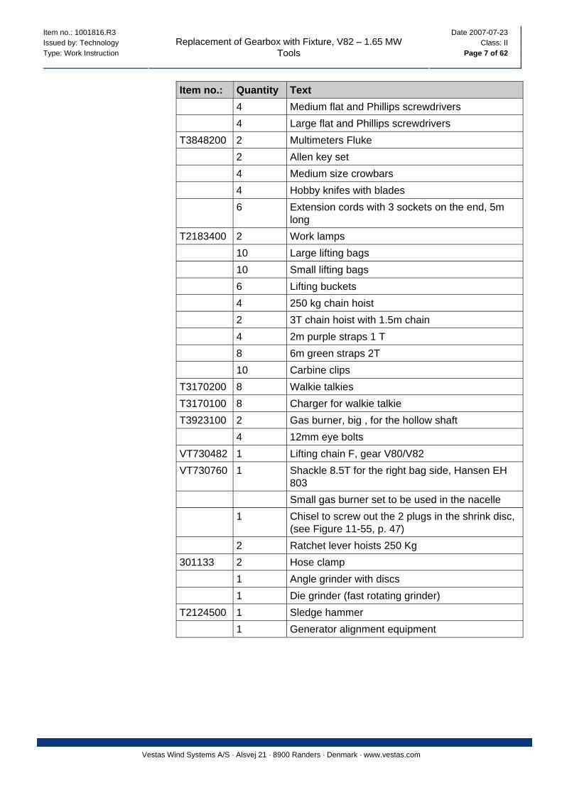
Item no.: Quantity Text 4 Medium flat and Phillips screwdrivers 4 Large flat and Phillips screwdrivers T3848200 2 Multimeters Fluke 2 Allen key set 4 Medium size crowbars 4 Hobby knifes with blades 6 Extension cords with 3 sockets on the end, 5m
long T2183400 2 Work lamps 10 Large lifting bags 10 Small lifting bags 6 Lifting buckets 4 250 kg chain hoist 2 3T chain hoist with 1.5m chain 4 2m purple straps 1 T 8 6m green straps 2T 10 Carbine clips T3170200 8 Walkie talkies T3170100 8 Charger for walkie talkie T3923100 2 Gas burner, big , for the hollow shaft 4 12mm eye bolts VT730482 1 Lifting chain F, gear V80/V82 VT730760 1 Shackle 8.5T for the right bag side, Hansen EH
803 Small gas burner set to be used in the nacelle 1 Chisel to screw out the 2 plugs in the shrink disc,
(see Figure 11-55, p. 47) 2 Ratchet lever hoists 250 Kg 301133 2 Hose clamp 1 Angle grinder with discs 1 Die grinder (fast rotating grinder) T2124500 1 Sledge hammer 1 Generator alignment equipment
Item no.: 1001816.R3 Date 2007-07-23 Issued by: Technology Class: II Type: Work Instruction Page 8 of 62
Replacement of Gearbox with Fixture, V82 – 1.65 MW Spare Parts
Vestas Wind Systems A/S · Alsvej 21 · 8900 Randers · Denmark · www.vestas.com
8 Spare Parts
Item no.: Quantity Text
Site specific
1 Oil filter
60060119 1 Blue paint RAL 5010 1 Black paint for the main shaft 1 White paint for the nacelle cover 226631 Universal cloth/rags Oil Rags 115517 Cable ties Solid plastic bags for blacking off the oil hoses and
fittings 198004 Cleaning paper Tork Multi 096189 1 Benzine 213619 1 Never Seez grease 149752 2 Sikaflex Adhesive RAL 9010 Emery cloth for the main shaft / hollow shaft 233843 1 Scotch Brite 3M 60072154 4 M60 Washer
9 Weights
Gearbox: approx. 17 T
10 Estimated Time Use
The time use is dependent on the number of service technicians and how experienced they are. The time use is also dependent of the weather, and situations like if the shrink disc and the brake disc have to be swapped over to the new gearbox or if these components are pre mounted.

Item no.: 1001816.R3 Date 2007-07-23 Issued by: Technology Class: II Type: Work Instruction Page 9 of 62
Replacement of Gearbox with Fixture, V82 – 1.65 MW Procedure
Vestas Wind Systems A/S · Alsvej 21 · 8900 Randers · Denmark · www.vestas.com
11 Procedure
11.1 Preparing of Rotor Lock
1. Prepare the rotor lock on the ground, and lift it up to the nacelle.
11.2 Preparing of Fixture
Figure 11-1: Fixture overview and parts
1 Crescent shaped flange against main bearing housing
4 Upper part of fixture body
2 Hydraulic cylinders 5 Crescent shaped flange against gearbox
3 Distance pieces depending on turbine type
6 Distance block for second gearbox push
7 Lower part of fixture body
Item no.: 1001816.R3 Date 2007-07-23 Issued by: Technology Class: II Type: Work Instruction Page 10 of 62
Replacement of Gearbox with Fixture, V82 – 1.65 MW Procedure
Vestas Wind Systems A/S · Alsvej 21 · 8900 Randers · Denmark · www.vestas.com
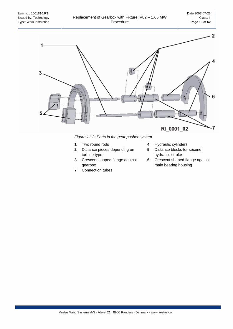
Figure 11-2: Parts in the gear pusher system
1 Two round rods 4 Hydraulic cylinders 2 Distance pieces depending on
turbine type 5 Distance blocks for second
hydraulic stroke 3 Crescent shaped flange against
gearbox 6 Crescent shaped flange against
main bearing housing 7 Connection tubes
Item no.: 1001816.R3 Date 2007-07-23 Issued by: Technology Class: II Type: Work Instruction Page 11 of 62
Replacement of Gearbox with Fixture, V82 – 1.65 MW Procedure
Vestas Wind Systems A/S · Alsvej 21 · 8900 Randers · Denmark · www.vestas.com
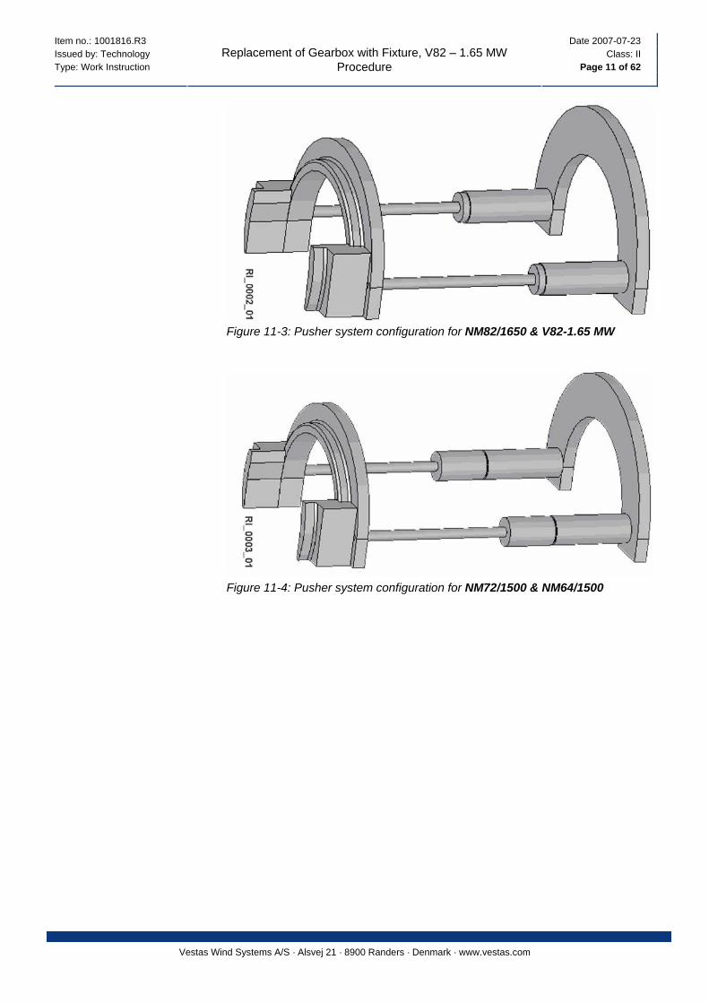
Figure 11-3: Pusher system configuration for NM82/1650 & V82-1.65 MW
Figure 11-4: Pusher system configuration for NM72/1500 & NM64/1500
Item no.: 1001816.R3 Date 2007-07-23 Issued by: Technology Class: II Type: Work Instruction Page 12 of 62
Replacement of Gearbox with Fixture, V82 – 1.65 MW Procedure
Vestas Wind Systems A/S · Alsvej 21 · 8900 Randers · Denmark · www.vestas.com
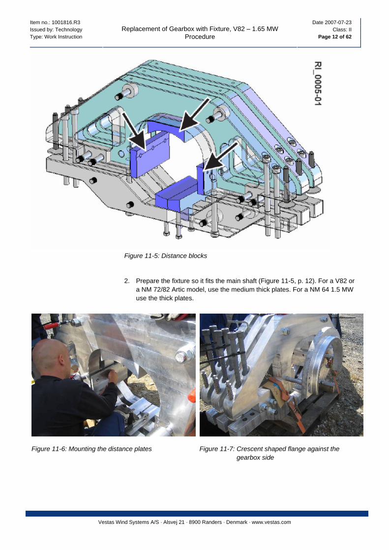
Figure 11-5: Distance blocks
2. Prepare the fixture so it fits the main shaft (Figure 11-5, p. 12). For a V82 or a NM 72/82 Artic model, use the medium thick plates. For a NM 64 1.5 MW use the thick plates.
Figure 11-6: Mounting the distance plates Figure 11-7: Crescent shaped flange against the gearbox side
Item no.: 1001816.R3 Date 2007-07-23 Issued by: Technology Class: II Type: Work Instruction Page 13 of 62
Replacement of Gearbox with Fixture, V82 – 1.65 MW Procedure
Vestas Wind Systems A/S · Alsvej 21 · 8900 Randers · Denmark · www.vestas.com
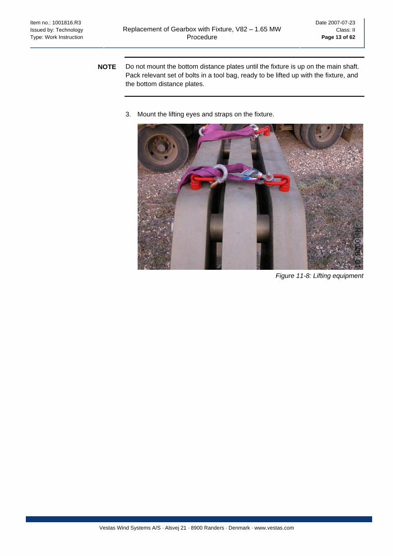
Do not mount the bottom distance plates until the fixture is up on the main shaft. Pack relevant set of bolts in a tool bag, ready to be lifted up with the fixture, and the bottom distance plates.
NOTE
3. Mount the lifting eyes and straps on the fixture.
Figure 11-8: Lifting equipment
Item no.: 1001816.R3 Date 2007-07-23 Issued by: Technology Class: II Type: Work Instruction Page 14 of 62
Replacement of Gearbox with Fixture, V82 – 1.65 MW Procedure
Vestas Wind Systems A/S · Alsvej 21 · 8900 Randers · Denmark · www.vestas.com
3
1
2
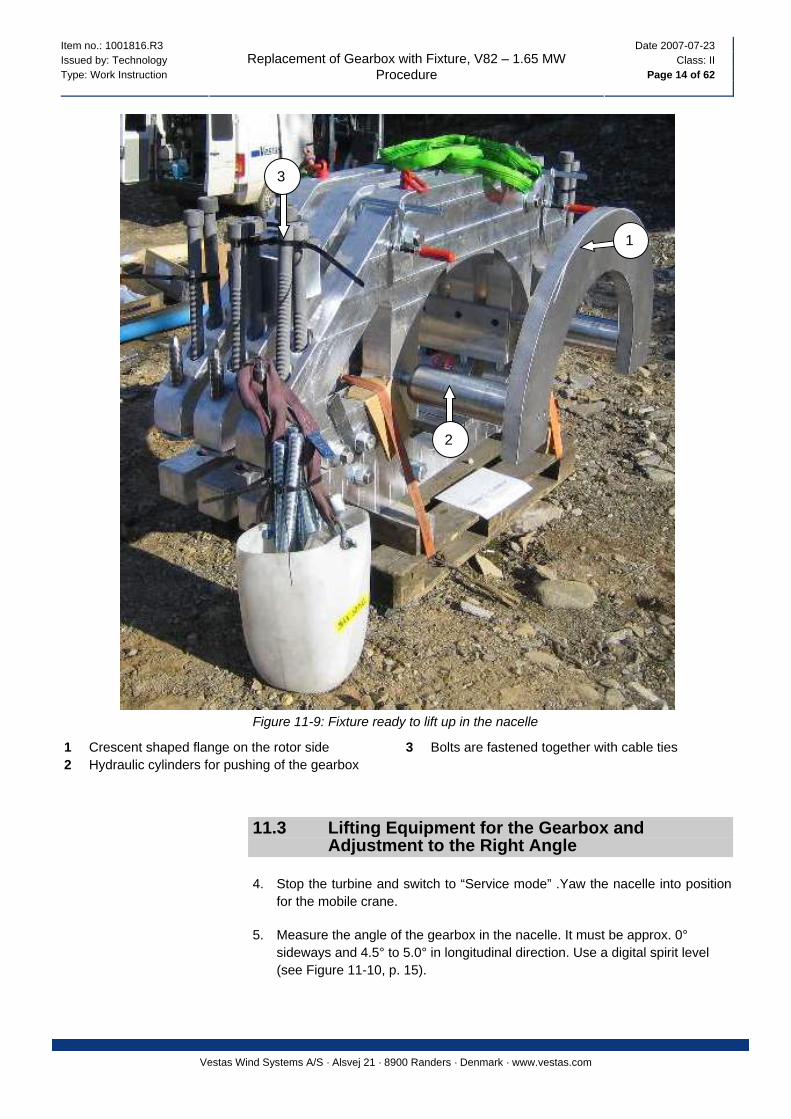
Figure 11-9: Fixture ready to lift up in the nacelle
1 Crescent shaped flange on the rotor side 3 Bolts are fastened together with cable ties 2 Hydraulic cylinders for pushing of the gearbox
11.3 Lifting Equipment for the Gearbox and Adjustment to the Right Angle
4. Stop the turbine and switch to “Service mode” .Yaw the nacelle into position for the mobile crane.
5. Measure the angle of the gearbox in the nacelle. It must be approx. 0° sideways and 4.5° to 5.0° in longitudinal direction. Use a digital spirit level (see Figure 11-10, p. 15).
Item no.: 1001816.R3 Date 2007-07-23 Issued by: Technology Class: II Type: Work Instruction Page 15 of 62
Replacement of Gearbox with Fixture, V82 – 1.65 MW Procedure
Vestas Wind Systems A/S · Alsvej 21 · 8900 Randers · Denmark · www.vestas.com
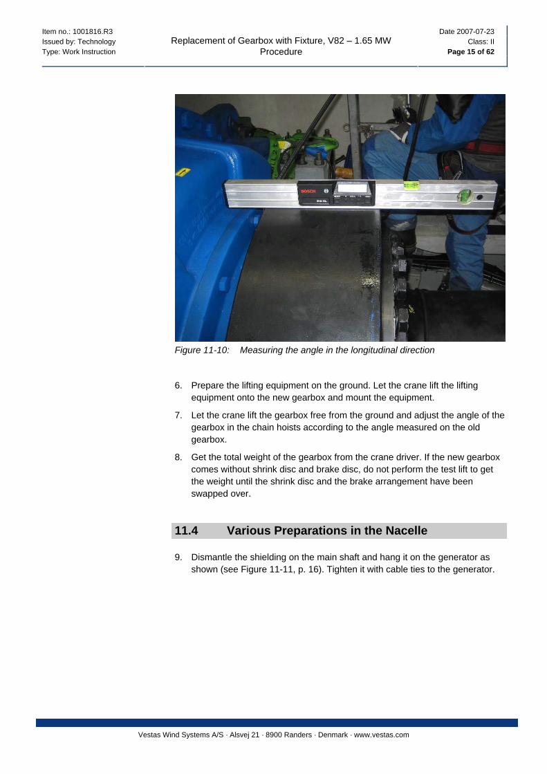
Figure 11-10: Measuring the angle in the longitudinal direction
6. Prepare the lifting equipment on the ground. Let the crane lift the lifting equipment onto the new gearbox and mount the equipment.
7. Let the crane lift the gearbox free from the ground and adjust the angle of the gearbox in the chain hoists according to the angle measured on the old gearbox.
8. Get the total weight of the gearbox from the crane driver. If the new gearbox comes without shrink disc and brake disc, do not perform the test lift to get the weight until the shrink disc and the brake arrangement have been swapped over.
11.4 Various Preparations in the Nacelle
9. Dismantle the shielding on the main shaft and hang it on the generator as shown (see Figure 11-11, p. 16). Tighten it with cable ties to the generator.
Item no.: 1001816.R3 Date 2007-07-23 Issued by: Technology Class: II Type: Work Instruction Page 16 of 62
Replacement of Gearbox with Fixture, V82 – 1.65 MW Procedure
Vestas Wind Systems A/S · Alsvej 21 · 8900 Randers · Denmark · www.vestas.com
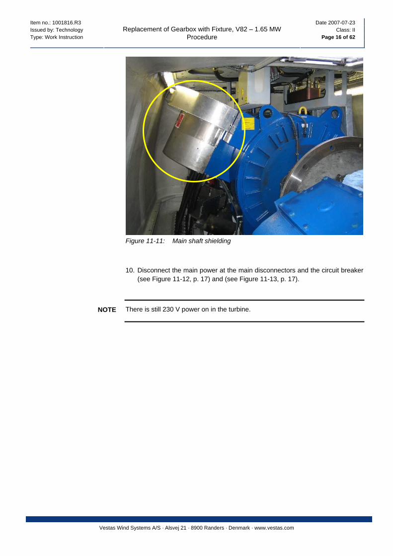
Figure 11-11: Main shaft shielding
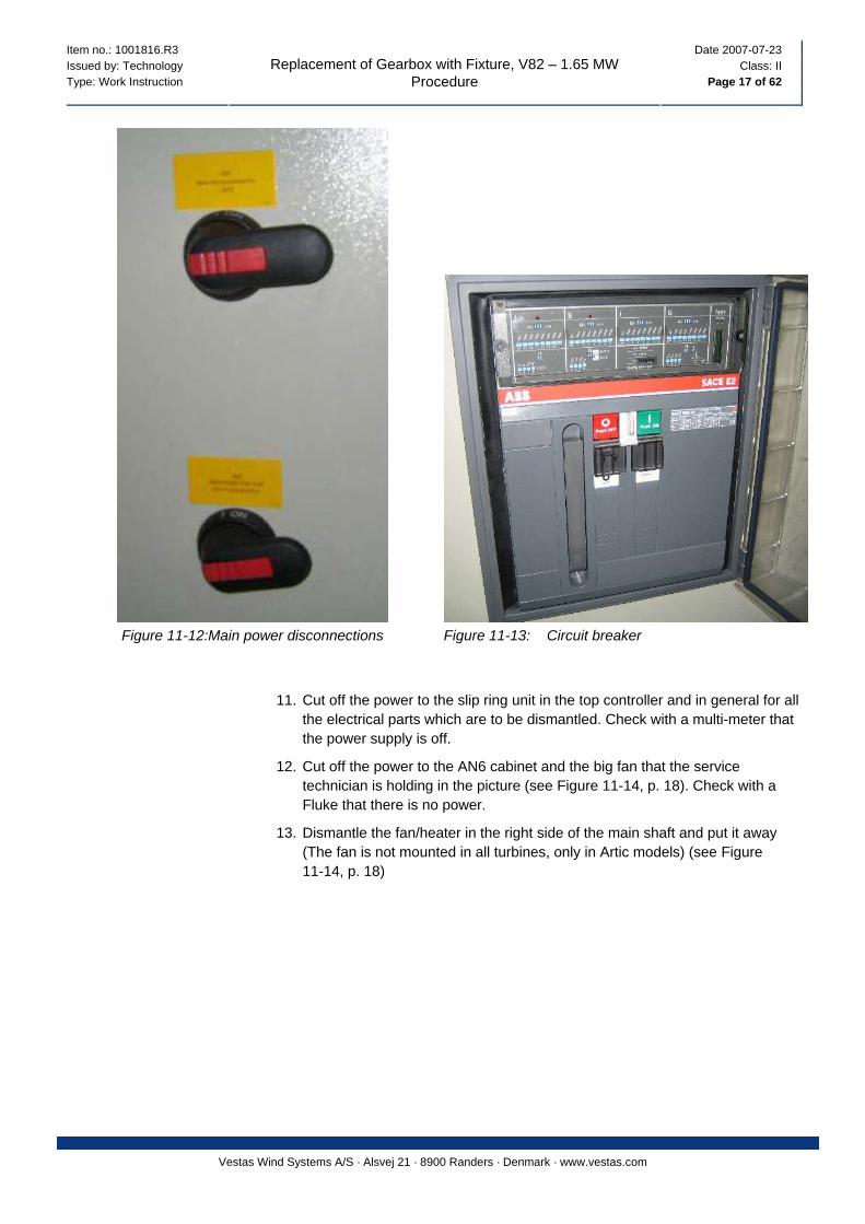
10. Disconnect the main power at the main disconnectors and the circuit breaker (see Figure 11-12, p. 17) and (see Figure 11-13, p. 17).
There is still 230 V power on in the turbine. NOTE
Item no.: 1001816.R3 Date 2007-07-23 Issued by: Technology Class: II Type: Work Instruction Page 17 of 62
Replacement of Gearbox with Fixture, V82 – 1.65 MW Procedure
Vestas Wind Systems A/S · Alsvej 21 · 8900 Randers · Denmark · www.vestas.com
Figure 11-12:Main power disconnections Figure 11-13: Circuit breaker
11. Cut off the power to the slip ring unit in the top controller and in general for all the electrical parts which are to be dismantled. Check with a multi-meter that the power supply is off.
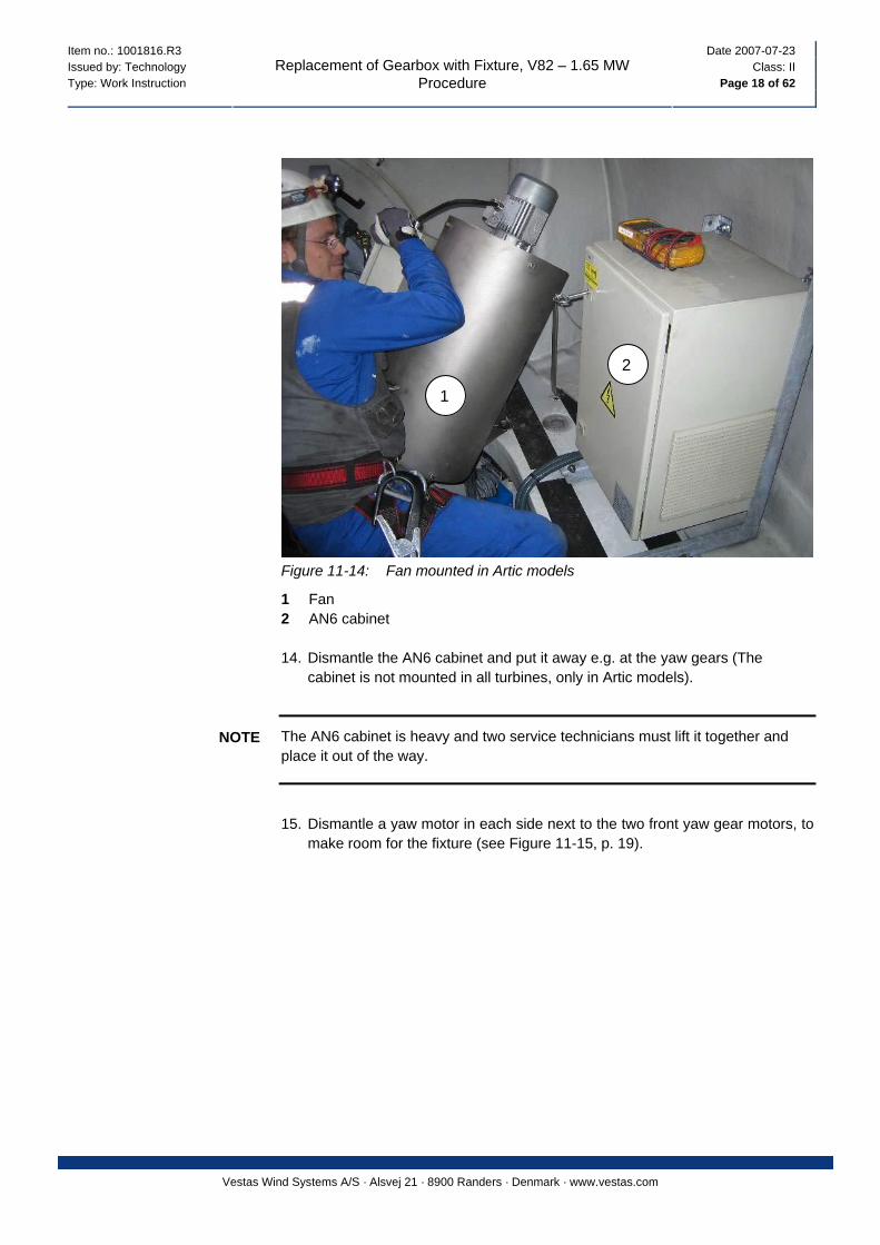
12. Cut off the power to the AN6 cabinet and the big fan that the service technician is holding in the picture (see Figure 11-14, p. 18). Check with a Fluke that there is no power.
13. Dismantle the fan/heater in the right side of the main shaft and put it away (The fan is not mounted in all turbines, only in Artic models) (see Figure 11-14, p. 18)
Item no.: 1001816.R3 Date 2007-07-23 Issued by: Technology Class: II Type: Work Instruction Page 18 of 62
Replacement of Gearbox with Fixture, V82 – 1.65 MW Procedure
Vestas Wind Systems A/S · Alsvej 21 · 8900 Randers · Denmark · www.vestas.com
2
1
Figure 11-14: Fan mounted in Artic models
1 Fan 2 AN6 cabinet 14. Dismantle the AN6 cabinet and put it away e.g. at the yaw gears (The
cabinet is not mounted in all turbines, only in Artic models).
The AN6 cabinet is heavy and two service technicians must lift it together and place it out of the way.
NOTE
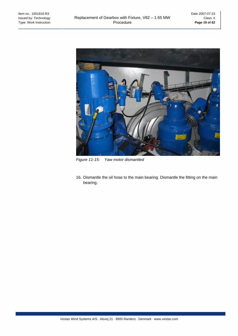
15. Dismantle a yaw motor in each side next to the two front yaw gear motors, to
make room for the fixture (see Figure 11-15, p. 19).
Item no.: 1001816.R3 Date 2007-07-23 Issued by: Technology Class: II Type: Work Instruction Page 19 of 62
Replacement of Gearbox with Fixture, V82 – 1.65 MW Procedure
Vestas Wind Systems A/S · Alsvej 21 · 8900 Randers · Denmark · www.vestas.com
Figure 11-15: Yaw motor dismantled
16. Dismantle the oil hose to the main bearing. Dismantle the fitting on the main bearing.
Item no.: 1001816.R3 Date 2007-07-23 Issued by: Technology Class: II Type: Work Instruction Page 20 of 62
Replacement of Gearbox with Fixture, V82 – 1.65 MW Procedure
Vestas Wind Systems A/S · Alsvej 21 · 8900 Randers · Denmark · www.vestas.com
2
1
3
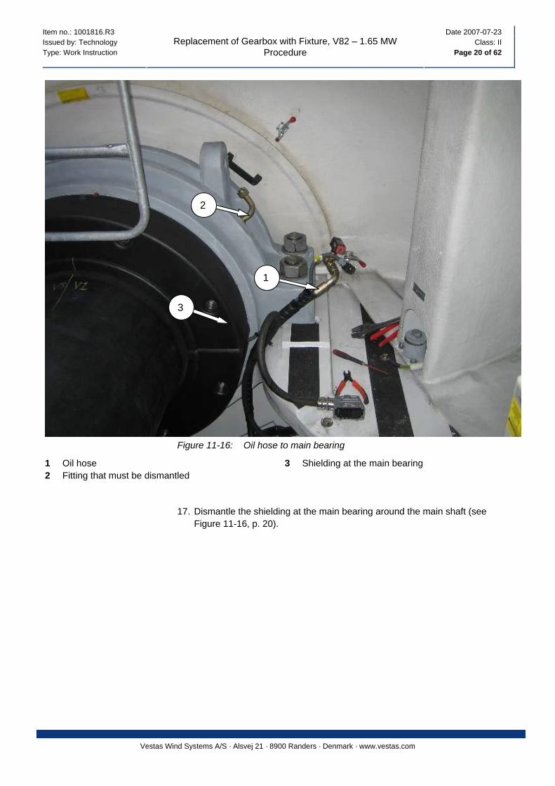
Figure 11-16: Oil hose to main bearing
1 Oil hose 3 Shielding at the main bearing 2 Fitting that must be dismantled
17. Dismantle the shielding at the main bearing around the main shaft (see Figure 11-16, p. 20).
Item no.: 1001816.R3 Date 2007-07-23 Issued by: Technology Class: II Type: Work Instruction Page 21 of 62
Replacement of Gearbox with Fixture, V82 – 1.65 MW Procedure
Vestas Wind Systems A/S · Alsvej 21 · 8900 Randers · Denmark · www.vestas.com
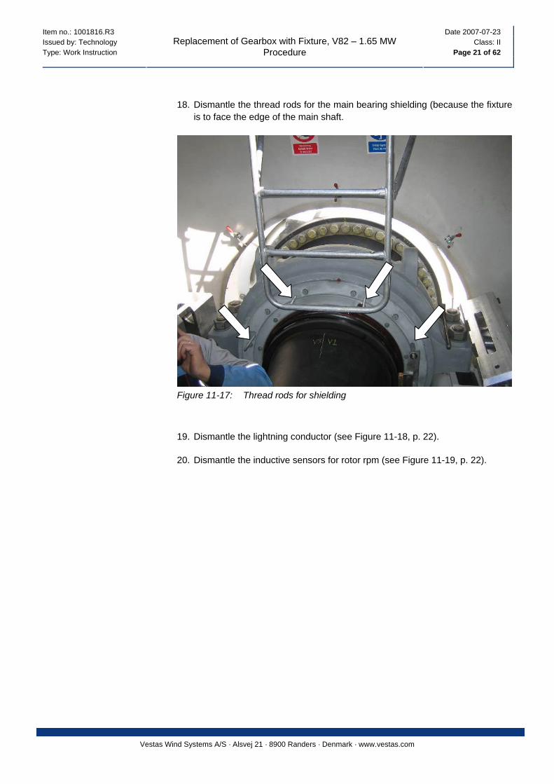
18. Dismantle the thread rods for the main bearing shielding (because the fixture is to face the edge of the main shaft.
Figure 11-17: Thread rods for shielding
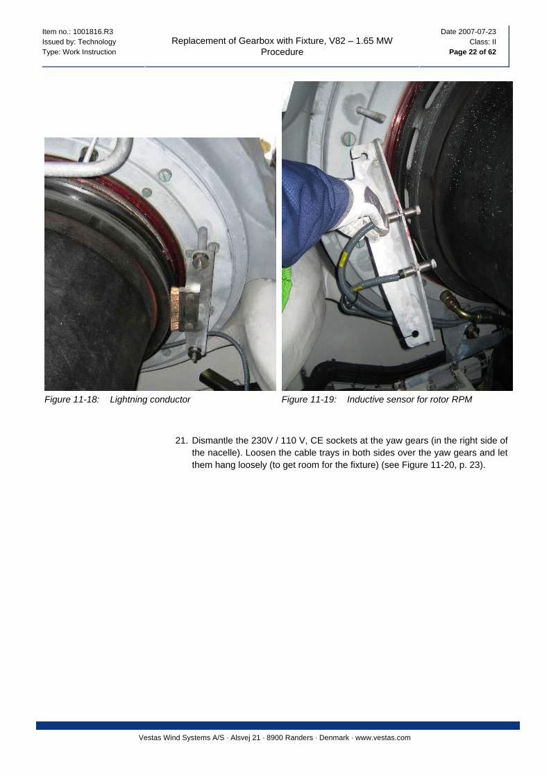
19. Dismantle the lightning conductor (see Figure 11-18, p. 22).
20. Dismantle the inductive sensors for rotor rpm (see Figure 11-19, p. 22).
Item no.: 1001816.R3 Date 2007-07-23 Issued by: Technology Class: II Type: Work Instruction Page 22 of 62
Replacement of Gearbox with Fixture, V82 – 1.65 MW Procedure
Vestas Wind Systems A/S · Alsvej 21 · 8900 Randers · Denmark · www.vestas.com
Figure 11-18: Lightning conductor Figure 11-19: Inductive sensor for rotor RPM
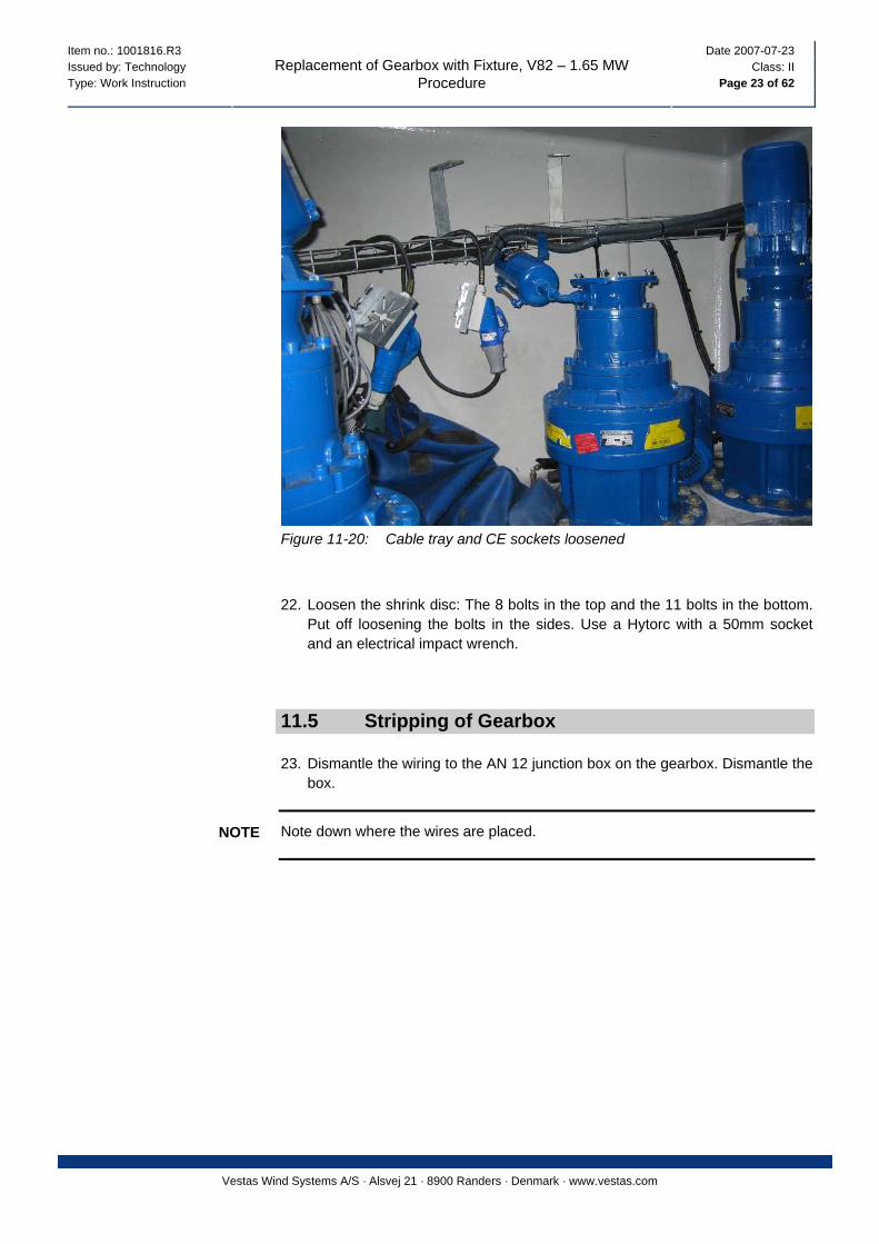
21. Dismantle the 230V / 110 V, CE sockets at the yaw gears (in the right side of the nacelle). Loosen the cable trays in both sides over the yaw gears and let them hang loosely (to get room for the fixture) (see Figure 11-20, p. 23).
Item no.: 1001816.R3 Date 2007-07-23 Issued by: Technology Class: II Type: Work Instruction Page 23 of 62
Replacement of Gearbox with Fixture, V82 – 1.65 MW Procedure
Vestas Wind Systems A/S · Alsvej 21 · 8900 Randers · Denmark · www.vestas.com
Figure 11-20: Cable tray and CE sockets loosened
22. Loosen the shrink disc: The 8 bolts in the top and the 11 bolts in the bottom. Put off loosening the bolts in the sides. Use a Hytorc with a 50mm socket and an electrical impact wrench.
11.5 Stripping of Gearbox
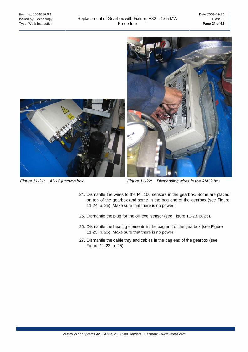
23. Dismantle the wiring to the AN 12 junction box on the gearbox. Dismantle the box.
Note down where the wires are placed. NOTE
Item no.: 1001816.R3 Date 2007-07-23 Issued by: Technology Class: II Type: Work Instruction Page 24 of 62
Replacement of Gearbox with Fixture, V82 – 1.65 MW Procedure
Vestas Wind Systems A/S · Alsvej 21 · 8900 Randers · Denmark · www.vestas.com
Figure 11-21: AN12 junction box Figure 11-22: Dismantling wires in the AN12 box
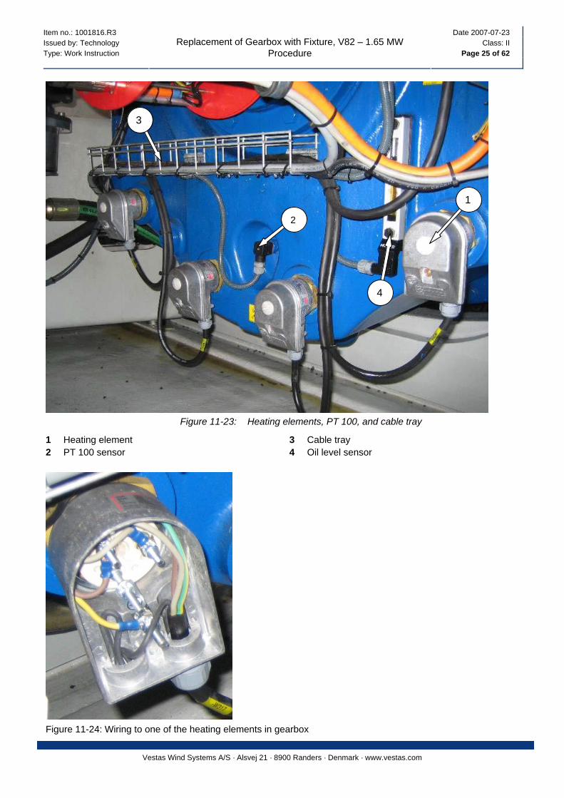
24. Dismantle the wires to the PT 100 sensors in the gearbox. Some are placed
on top of the gearbox and some in the bag end of the gearbox (see Figure 11-24, p. 25). Make sure that there is no power!
25. Dismantle the plug for the oil level sensor (see Figure 11-23, p. 25).
26. Dismantle the heating elements in the bag end of the gearbox (see Figure 11-23, p. 25). Make sure that there is no power!
27. Dismantle the cable tray and cables in the bag end of the gearbox (see Figure 11-23, p. 25).
Item no.: 1001816.R3 Date 2007-07-23 Issued by: Technology Class: II Type: Work Instruction Page 25 of 62
Replacement of Gearbox with Fixture, V82 – 1.65 MW Procedure
Vestas Wind Systems A/S · Alsvej 21 · 8900 Randers · Denmark · www.vestas.com
3
1
2
4
Figure 11-23: Heating elements, PT 100, and cable tray
1 Heating element 3 Cable tray 2 PT 100 sensor 4 Oil level sensor
Figure 11-24: Wiring to one of the heating elements in gearbox
Item no.: 1001816.R3 Date 2007-07-23 Issued by: Technology Class: II Type: Work Instruction Page 26 of 62
Replacement of Gearbox with Fixture, V82 – 1.65 MW Procedure
Vestas Wind Systems A/S · Alsvej 21 · 8900 Randers · Denmark · www.vestas.com
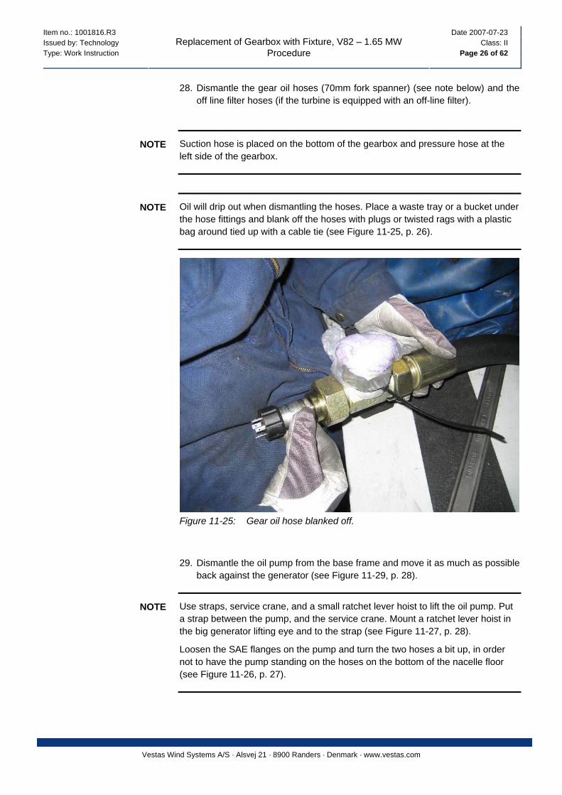
28. Dismantle the gear oil hoses (70mm fork spanner) (see note below) and the off line filter hoses (if the turbine is equipped with an off-line filter).
Suction hose is placed on the bottom of the gearbox and pressure hose at the left side of the gearbox.
NOTE
Oil will drip out when dismantling the hoses. Place a waste tray or a bucket under the hose fittings and blank off the hoses with plugs or twisted rags with a plastic bag around tied up with a cable tie (see Figure 11-25, p. 26).
NOTE
Figure 11-25: Gear oil hose blanked off.
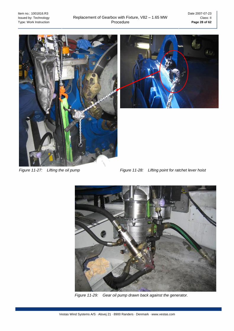
29. Dismantle the oil pump from the base frame and move it as much as possible back against the generator (see Figure 11-29, p. 28).
Use straps, service crane, and a small ratchet lever hoist to lift the oil pump. Put a strap between the pump, and the service crane. Mount a ratchet lever hoist in the big generator lifting eye and to the strap (see Figure 11-27, p. 28).
NOTE
Loosen the SAE flanges on the pump and turn the two hoses a bit up, in order not to have the pump standing on the hoses on the bottom of the nacelle floor (see Figure 11-26, p. 27).

Item no.: 1001816.R3 Date 2007-07-23 Issued by: Technology Class: II Type: Work Instruction Page 27 of 62
Replacement of Gearbox with Fixture, V82 – 1.65 MW Procedure
Vestas Wind Systems A/S · Alsvej 21 · 8900 Randers · Denmark · www.vestas.com
1
2
2
Figure 11-26: Gear oil pump
1 Lifting strap 2 SAE flanges
Item no.: 1001816.R3 Date 2007-07-23 Issued by: Technology Class: II Type: Work Instruction Page 28 of 62
Replacement of Gearbox with Fixture, V82 – 1.65 MW Procedure
Vestas Wind Systems A/S · Alsvej 21 · 8900 Randers · Denmark · www.vestas.com
Figure 11-27: Lifting the oil pump Figure 11-28: Lifting point for ratchet lever hoist
Figure 11-29: Gear oil pump drawn back against the generator.
Item no.: 1001816.R3 Date 2007-07-23 Issued by: Technology Class: II Type: Work Instruction Page 29 of 62
Replacement of Gearbox with Fixture, V82 – 1.65 MW Procedure
Vestas Wind Systems A/S · Alsvej 21 · 8900 Randers · Denmark · www.vestas.com
11.6 Slip Ring Unit and Rotating Union
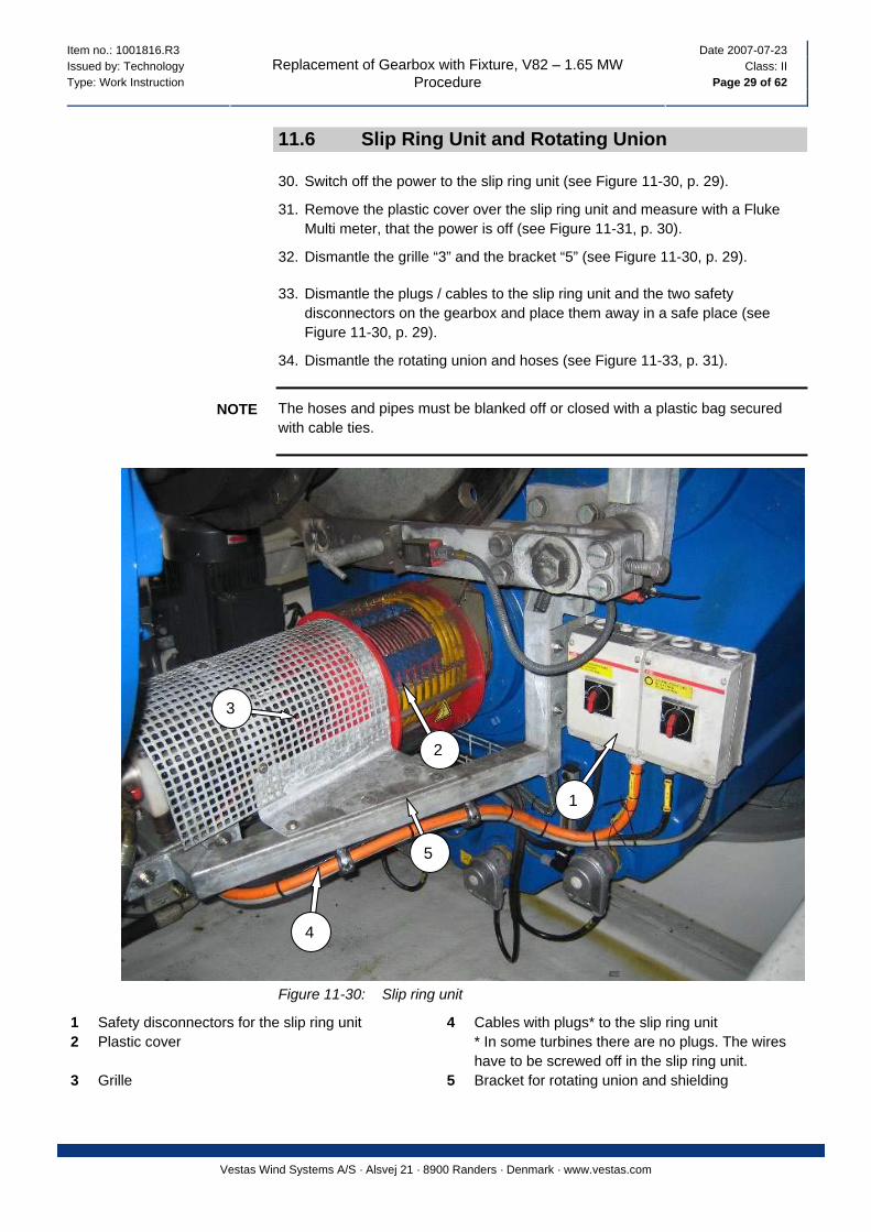
30. Switch off the power to the slip ring unit (see Figure 11-30, p. 29).
31. Remove the plastic cover over the slip ring unit and measure with a Fluke Multi meter, that the power is off (see Figure 11-31, p. 30).
32. Dismantle the grille “3” and the bracket “5” (see Figure 11-30, p. 29).
33. Dismantle the plugs / cables to the slip ring unit and the two safety disconnectors on the gearbox and place them away in a safe place (see Figure 11-30, p. 29).
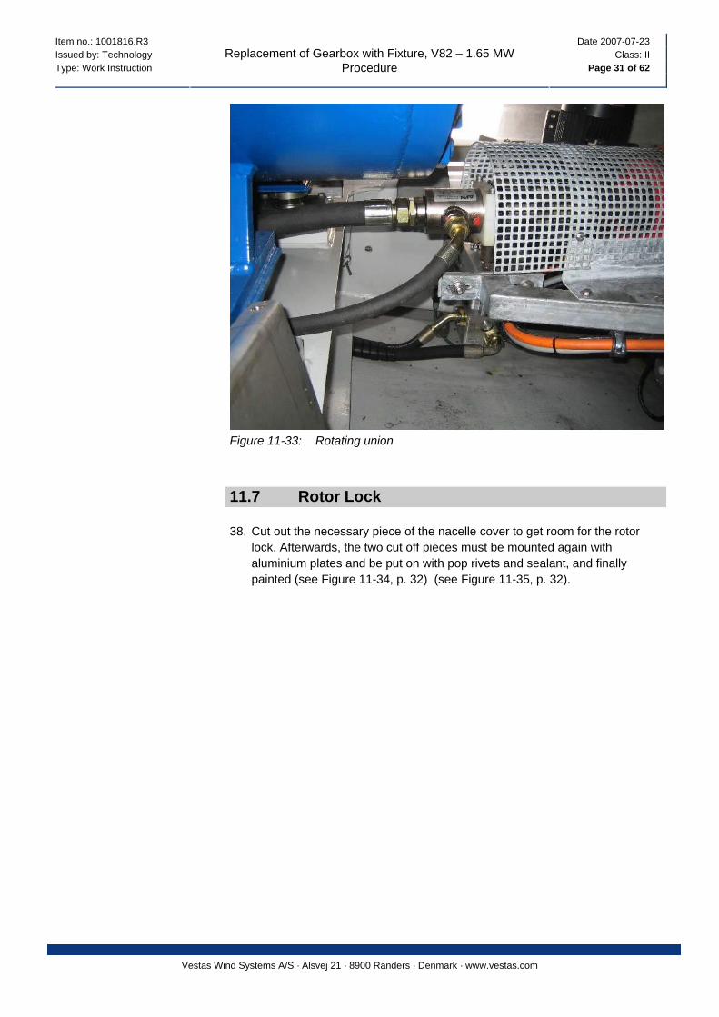
34. Dismantle the rotating union and hoses (see Figure 11-33, p. 31).
The hoses and pipes must be blanked off or closed with a plastic bag secured with cable ties.
NOTE
2
3
1
5
4
Figure 11-30: Slip ring unit
1 Safety disconnectors for the slip ring unit 4 Cables with plugs* to the slip ring unit 2 Plastic cover * In some turbines there are no plugs. The wires
have to be screwed off in the slip ring unit. 3 Grille 5 Bracket for rotating union and shielding
Item no.: 1001816.R3 Date 2007-07-23 Issued by: Technology Class: II Type: Work Instruction Page 30 of 62
Replacement of Gearbox with Fixture, V82 – 1.65 MW Procedure
Vestas Wind Systems A/S · Alsvej 21 · 8900 Randers · Denmark · www.vestas.com
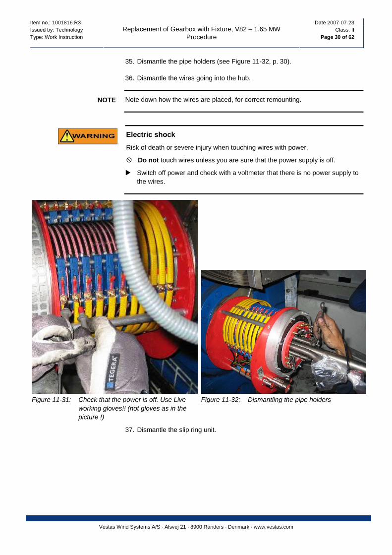
35. Dismantle the pipe holders (see Figure 11-32, p. 30).
36. Dismantle the wires going into the hub.
Note down how the wires are placed, for correct remounting. NOTE
Electric shock
Risk of death or severe injury when touching wires with power.
Do not touch wires unless you are sure that the power supply is off.
Switch off power and check with a voltmeter that there is no power supply to the wires.
Figure 11-31: Check that the power is off. Use Live working gloves!! (not gloves as in the picture !)
Figure 11-32: Dismantling the pipe holders
37. Dismantle the slip ring unit.
Item no.: 1001816.R3 Date 2007-07-23 Issued by: Technology Class: II Type: Work Instruction Page 31 of 62
Replacement of Gearbox with Fixture, V82 – 1.65 MW Procedure
Vestas Wind Systems A/S · Alsvej 21 · 8900 Randers · Denmark · www.vestas.com
Figure 11-33: Rotating union
11.7 Rotor Lock
38. Cut out the necessary piece of the nacelle cover to get room for the rotor lock. Afterwards, the two cut off pieces must be mounted again with aluminium plates and be put on with pop rivets and sealant, and finally painted (see Figure 11-34, p. 32) (see Figure 11-35, p. 32).

Item no.: 1001816.R3 Date 2007-07-23 Issued by: Technology Class: II Type: Work Instruction Page 32 of 62
Replacement of Gearbox with Fixture, V82 – 1.65 MW Procedure
Vestas Wind Systems A/S · Alsvej 21 · 8900 Randers · Denmark · www.vestas.com
Figure 11-34: Make a cut out in the nacelle cover with a bayonet saw
Figure 11-35: Cut out following the yellow line in this figure
39. Position the rotor with 2 blades up (“bunny ears”), so that the yellow rotor hooking point is pointing up. Check through the hatch that it is positioned correctly.
Item no.: 1001816.R3 Date 2007-07-23 Issued by: Technology Class: II Type: Work Instruction Page 33 of 62
Replacement of Gearbox with Fixture, V82 – 1.65 MW Procedure
Vestas Wind Systems A/S · Alsvej 21 · 8900 Randers · Denmark · www.vestas.com
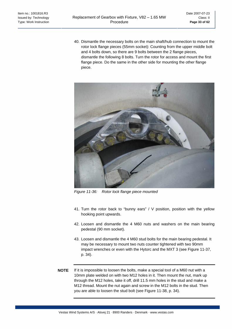
40. Dismantle the necessary bolts on the main shaft/hub connection to mount the
rotor lock flange pieces (55mm socket): Counting from the upper middle bolt and 4 bolts down, so there are 9 bolts between the 2 flange pieces, dismantle the following 8 bolts. Turn the rotor for access and mount the first flange piece. Do the same in the other side for mounting the other flange piece.
Figure 11-36: Rotor lock flange piece mounted
41. Turn the rotor back to “bunny ears” / V position, position with the yellow hooking point upwards.
42. Loosen and dismantle the 4 M60 nuts and washers on the main bearing pedestal (90 mm socket).
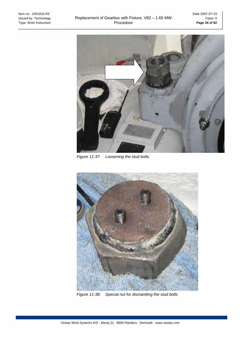
43. Loosen and dismantle the 4 M60 stud bolts for the main bearing pedestal. It may be necessary to mount two nuts counter tightened with two 90mm impact wrenches or even with the Hytorc and the MXT 3 (see Figure 11-37, p. 34).
If it is impossible to loosen the bolts, make a special tool of a M60 nut with a 10mm plate welded on with two M12 holes in it. Then mount the nut, mark up through the M12 holes, take it off, drill 11.5 mm holes in the stud and make a M12 thread. Mount the nut again and screw in the M12 bolts in the stud. Then you are able to loosen the stud bolt (see Figure 11-38, p. 34).
NOTE
Item no.: 1001816.R3 Date 2007-07-23 Issued by: Technology Class: II Type: Work Instruction Page 34 of 62
Replacement of Gearbox with Fixture, V82 – 1.65 MW Procedure
Vestas Wind Systems A/S · Alsvej 21 · 8900 Randers · Denmark · www.vestas.com
Figure 11-37: Loosening the stud bolts.
Figure 11-38: Special nut for dismantling the stud bolts

Item no.: 1001816.R3 Date 2007-07-23 Issued by: Technology Class: II Type: Work Instruction Page 35 of 62
Replacement of Gearbox with Fixture, V82 – 1.65 MW Procedure
Vestas Wind Systems A/S · Alsvej 21 · 8900 Randers · Denmark · www.vestas.com
44. Mount the rotor lock frames. They must turn with the thread holes in the ends to the back.
1
2
3
Figure 11-39: Right rotor lock
1 Rotor lock frame, right hand side 2 Lock pin 3 Thread holes in the end of the frame 45. Mount the new long stud bolts, and screw them down so that 50mm thread is
sticking up.
46. Mount the M60 nuts and new washers. Tighten them up with the hytorc and the MXT3 or MXT10 to 2000Nm.
47. Mount the rotor lock pins (see Figure 11-40, p. 36).
Item no.: 1001816.R3 Date 2007-07-23 Issued by: Technology Class: II Type: Work Instruction Page 36 of 62
Replacement of Gearbox with Fixture, V82 – 1.65 MW Procedure
Vestas Wind Systems A/S · Alsvej 21 · 8900 Randers · Denmark · www.vestas.com
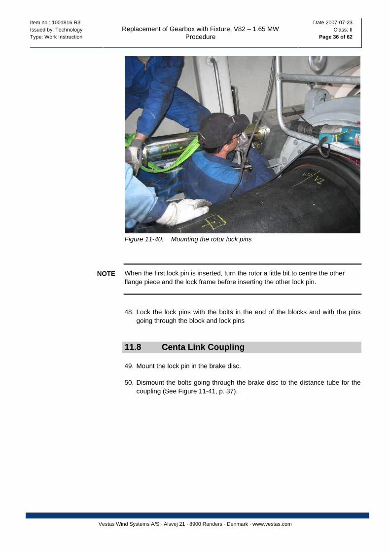
Figure 11-40: Mounting the rotor lock pins
When the first lock pin is inserted, turn the rotor a little bit to centre the other flange piece and the lock frame before inserting the other lock pin.
NOTE
48. Lock the lock pins with the bolts in the end of the blocks and with the pins
going through the block and lock pins
11.8 Centa Link Coupling
49. Mount the lock pin in the brake disc.
50. Dismount the bolts going through the brake disc to the distance tube for the coupling (See Figure 11-41, p. 37).
Item no.: 1001816.R3 Date 2007-07-23 Issued by: Technology Class: II Type: Work Instruction Page 37 of 62
Replacement of Gearbox with Fixture, V82 – 1.65 MW Procedure
Vestas Wind Systems A/S · Alsvej 21 · 8900 Randers · Denmark · www.vestas.com
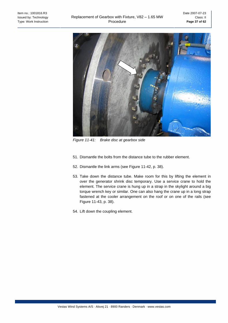
Figure 11-41: Brake disc at gearbox side
51. Dismantle the bolts from the distance tube to the rubber element.
52. Dismantle the link arms (see Figure 11-42, p. 38).
53. Take down the distance tube. Make room for this by lifting the element in over the generator shrink disc temporary. Use a service crane to hold the element. The service crane is hung up in a strap in the skylight around a big torque wrench key or similar. One can also hang the crane up in a long strap fastened at the cooler arrangement on the roof or on one of the rails (see Figure 11-43, p. 38).
54. Lift down the coupling element.
Item no.: 1001816.R3 Date 2007-07-23 Issued by: Technology Class: II Type: Work Instruction Page 38 of 62
Replacement of Gearbox with Fixture, V82 – 1.65 MW Procedure
Vestas Wind Systems A/S · Alsvej 21 · 8900 Randers · Denmark · www.vestas.com
3 2
5 4
1
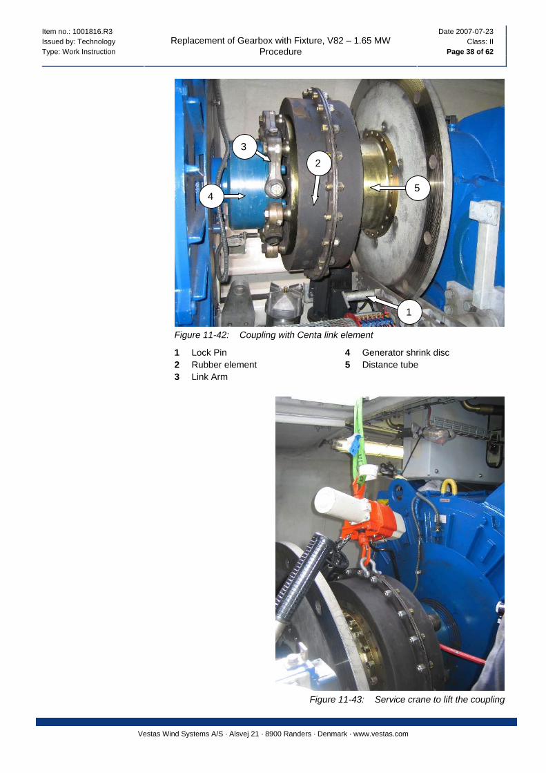
Figure 11-42: Coupling with Centa link element
1 Lock Pin 4 Generator shrink disc 2 Rubber element 5 Distance tube 3 Link Arm
Figure 11-43: Service crane to lift the coupling
Item no.: 1001816.R3 Date 2007-07-23 Issued by: Technology Class: II Type: Work Instruction Page 39 of 62
Replacement of Gearbox with Fixture, V82 – 1.65 MW Procedure
Vestas Wind Systems A/S · Alsvej 21 · 8900 Randers · Denmark · www.vestas.com
55. Mark the generator shrink disc inner and outer elements to be sure to be able
to mount it correctly again. Dismantle it by manoeuvring it out with a crowbar when the bolts are dismantled.
When mounting the coupling again, lift the element up over the generator shrink disc, mount the distance tube to the brake disc. Lift the element in place and tighten it to the distance tube. Mount the link elements first at the generator, then at the coupling. Never do it in the top, first in the sides and bottom.
NOTE
If a link element is damaged and has to be replaced, all the link elements must be replaced at the same time, because they are balanced together.
NOTE
11.9 Moving the Generator
56. In some of the turbines (twin speed) there is not much room to get the gearbox out; therefore the generator has to be pushed backwards as far as possible. Loosen the generator and push it with the hydraulic jacks from the fixture.
Secure the generator with bolts, to prevent it from falling out of the nacelle. NOTE
11.10 Preparation in the Hub
57. Relief the hydraulic pressure in the hub on the 4 needle valves for the pitch.
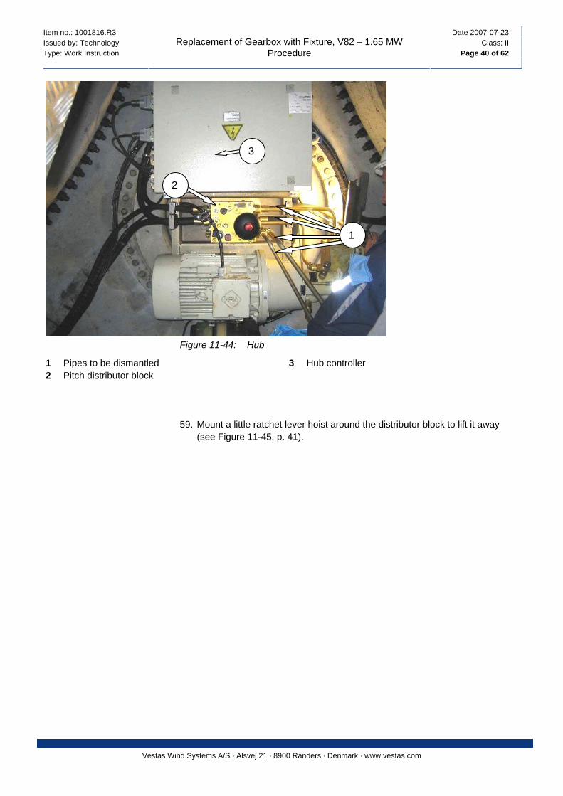
58. Dismount the pipes at the pitch distributor block, and plug up the block and pipes with blind plugs or small rags
Item no.: 1001816.R3 Date 2007-07-23 Issued by: Technology Class: II Type: Work Instruction Page 40 of 62
Replacement of Gearbox with Fixture, V82 – 1.65 MW Procedure
Vestas Wind Systems A/S · Alsvej 21 · 8900 Randers · Denmark · www.vestas.com
3
2
1
Figure 11-44: Hub
1 Pipes to be dismantled 3 Hub controller 2 Pitch distributor block
59. Mount a little ratchet lever hoist around the distributor block to lift it away (see Figure 11-45, p. 41).
Item no.: 1001816.R3 Date 2007-07-23 Issued by: Technology Class: II Type: Work Instruction Page 41 of 62
Replacement of Gearbox with Fixture, V82 – 1.65 MW Procedure
Vestas Wind Systems A/S · Alsvej 21 · 8900 Randers · Denmark · www.vestas.com
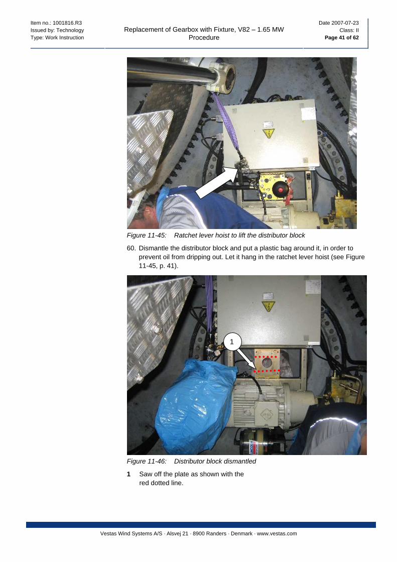
Figure 11-45: Ratchet lever hoist to lift the distributor block
60. Dismantle the distributor block and put a plastic bag around it, in order to prevent oil from dripping out. Let it hang in the ratchet lever hoist (see Figure 11-45, p. 41).
1
Figure 11-46: Distributor block dismantled
1 Saw off the plate as shown with the red dotted line.
Item no.: 1001816.R3 Date 2007-07-23 Issued by: Technology Class: II Type: Work Instruction Page 42 of 62
Replacement of Gearbox with Fixture, V82 – 1.65 MW Procedure
Vestas Wind Systems A/S · Alsvej 21 · 8900 Randers · Denmark · www.vestas.com
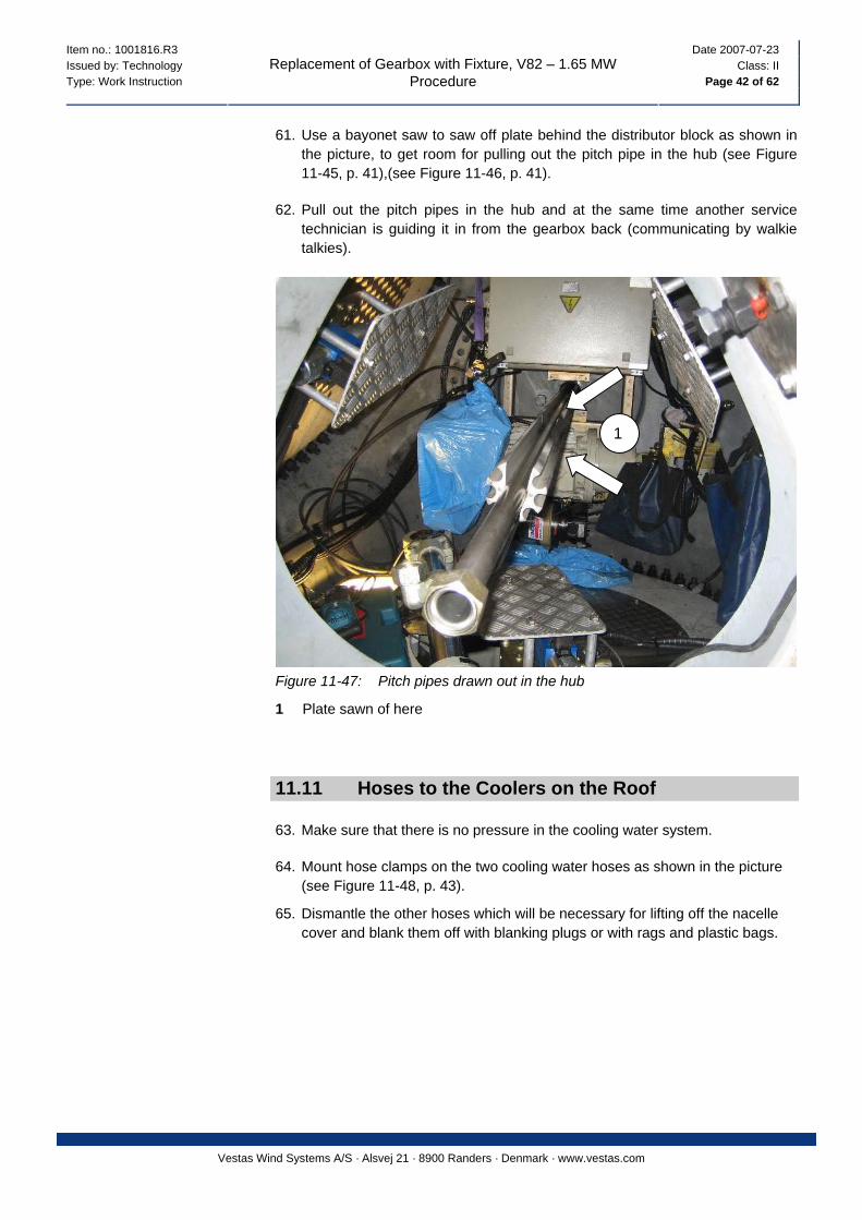
61. Use a bayonet saw to saw off plate behind the distributor block as shown in the picture, to get room for pulling out the pitch pipe in the hub (see Figure 11-45, p. 41),(see Figure 11-46, p. 41).
62. Pull out the pitch pipes in the hub and at the same time another service technician is guiding it in from the gearbox back (communicating by walkie talkies).
1
Figure 11-47: Pitch pipes drawn out in the hub
1 Plate sawn of here 11.11 Hoses to the Coolers on the Roof
63. Make sure that there is no pressure in the cooling water system.
64. Mount hose clamps on the two cooling water hoses as shown in the picture (see Figure 11-48, p. 43).
65. Dismantle the other hoses which will be necessary for lifting off the nacelle cover and blank them off with blanking plugs or with rags and plastic bags.

Item no.: 1001816.R3 Date 2007-07-23 Issued by: Technology Class: II Type: Work Instruction Page 43 of 62
Replacement of Gearbox with Fixture, V82 – 1.65 MW Procedure
Vestas Wind Systems A/S · Alsvej 21 · 8900 Randers · Denmark · www.vestas.com
Figure 11-48: Hose clamps mounted
66. Loosen and dismantle the water hose under the water pump and hold a
bucket underneath to collect approx. 5L of coolant.
Figure 11-49: Hose at water pump
Item no.: 1001816.R3 Date 2007-07-23 Issued by: Technology Class: II Type: Work Instruction Page 44 of 62
Replacement of Gearbox with Fixture, V82 – 1.65 MW Procedure
Vestas Wind Systems A/S · Alsvej 21 · 8900 Randers · Denmark · www.vestas.com
11.12 Cables and Wires
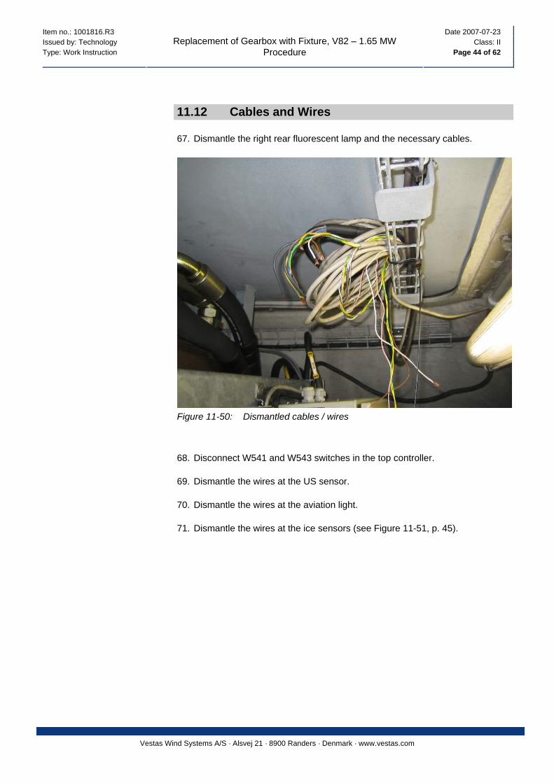
67. Dismantle the right rear fluorescent lamp and the necessary cables.
Figure 11-50: Dismantled cables / wires
68. Disconnect W541 and W543 switches in the top controller.
69. Dismantle the wires at the US sensor.
70. Dismantle the wires at the aviation light.
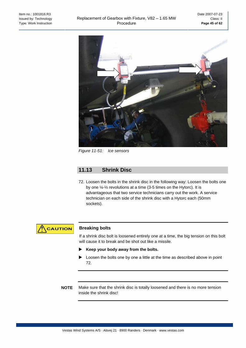
71. Dismantle the wires at the ice sensors (see Figure 11-51, p. 45).
Item no.: 1001816.R3 Date 2007-07-23 Issued by: Technology Class: II Type: Work Instruction Page 45 of 62
Replacement of Gearbox with Fixture, V82 – 1.65 MW Procedure
Vestas Wind Systems A/S · Alsvej 21 · 8900 Randers · Denmark · www.vestas.com
Figure 11-51: Ice sensors
11.13 Shrink Disc
72. Loosen the bolts in the shrink disc in the following way: Loosen the bolts one by one ¼-½ revolutions at a time (3-5 times on the Hytorc). It is advantageous that two service technicians carry out the work. A service technician on each side of the shrink disc with a Hytorc each (50mm sockets).
Breaking bolts
If a shrink disc bolt is loosened entirely one at a time, the big tension on this bolt will cause it to break and be shot out like a missile.
Keep your body away from the bolts.
Loosen the bolts one by one a little at the time as described above in point 72.
Make sure that the shrink disc is totally loosened and there is no more tension inside the shrink disc!
NOTE
Item no.: 1001816.R3 Date 2007-07-23 Issued by: Technology Class: II Type: Work Instruction Page 46 of 62
Replacement of Gearbox with Fixture, V82 – 1.65 MW Procedure
Vestas Wind Systems A/S · Alsvej 21 · 8900 Randers · Denmark · www.vestas.com
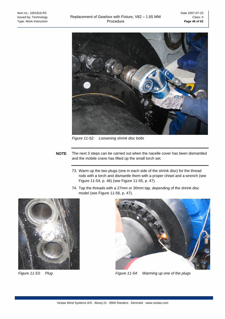
Figure 11-52: Loosening shrink disc bolts
The next 3 steps can be carried out when the nacelle cover has been dismantled and the mobile crane has lifted up the small torch set.
NOTE
73. Warm up the two plugs (one in each side of the shrink disc) for the thread rods with a torch and dismantle them with a proper chisel and a wrench (see Figure 11-54, p. 46) (see Figure 11-55, p. 47).
74. Tap the threads with a 27mm or 30mm tap, depending of the shrink disc model (see Figure 11-56, p. 47).
Figure 11-53: Plug Figure 11-54: Warming up one of the plugs

Item no.: 1001816.R3 Date 2007-07-23 Issued by: Technology Class: II Type: Work Instruction Page 47 of 62
Replacement of Gearbox with Fixture, V82 – 1.65 MW Procedure
Vestas Wind Systems A/S · Alsvej 21 · 8900 Randers · Denmark · www.vestas.com
Figure 11-55: Plug is screwed out. Figure 11-56: Thread is tapped.
75. Screw in a bolt or a threaded rod with a nut welded on, or as shown in the picture with a counter nut. The bolts are screwed in to secure, that the shrink disc is completely loosened.
Figure 11-57: 27 mm bolt or 30mm bolt / threaded rod is screwed in
Item no.: 1001816.R3 Date 2007-07-23 Issued by: Technology Class: II Type: Work Instruction Page 48 of 62
Replacement of Gearbox with Fixture, V82 – 1.65 MW Procedure
Vestas Wind Systems A/S · Alsvej 21 · 8900 Randers · Denmark · www.vestas.com
11.14 Torque Arms
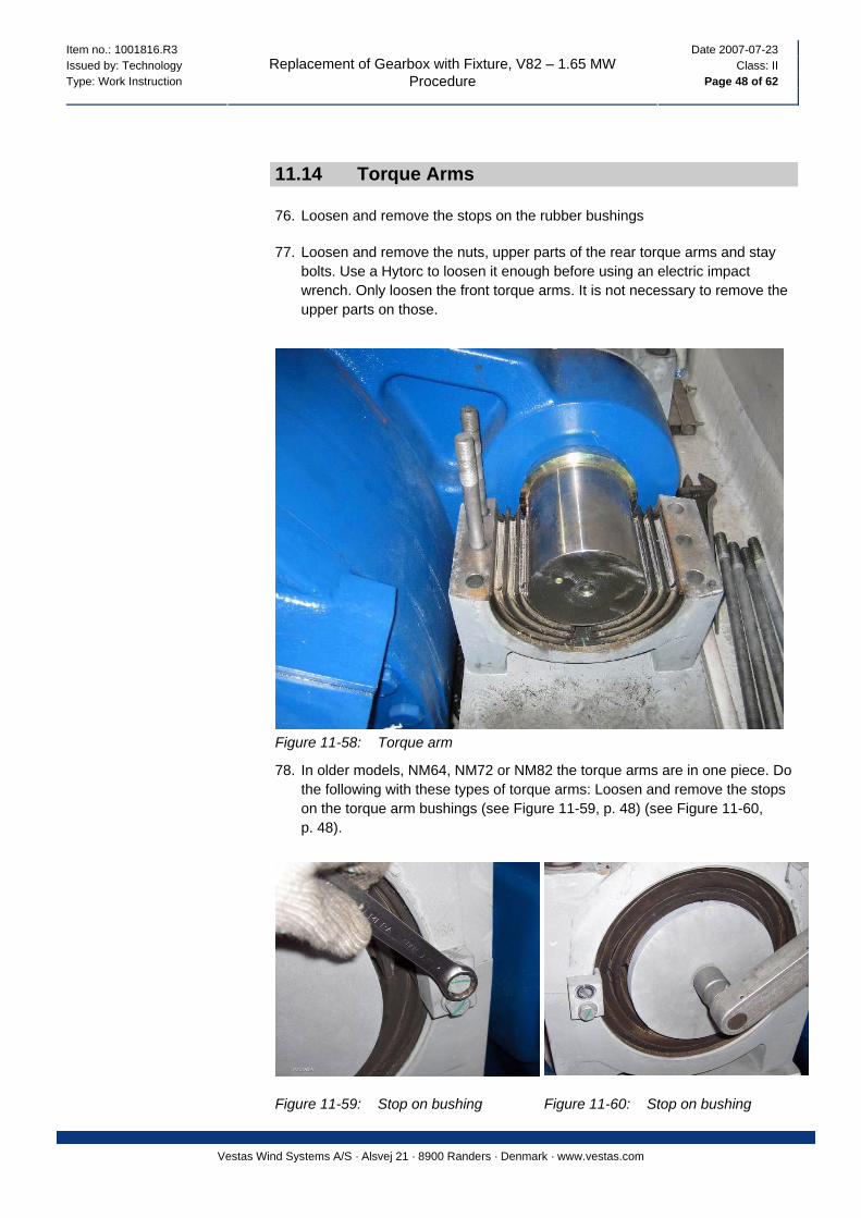
76. Loosen and remove the stops on the rubber bushings
77. Loosen and remove the nuts, upper parts of the rear torque arms and stay bolts. Use a Hytorc to loosen it enough before using an electric impact wrench. Only loosen the front torque arms. It is not necessary to remove the upper parts on those.
Figure 11-58: Torque arm
78. In older models, NM64, NM72 or NM82 the torque arms are in one piece. Do the following with these types of torque arms: Loosen and remove the stops on the torque arm bushings (see Figure 11-59, p. 48) (see Figure 11-60, p. 48).
Figure 11-59: Stop on bushing Figure 11-60: Stop on bushing
Item no.: 1001816.R3 Date 2007-07-23 Issued by: Technology Class: II Type: Work Instruction Page 49 of 62
Replacement of Gearbox with Fixture, V82 – 1.65 MW Procedure
Vestas Wind Systems A/S · Alsvej 21 · 8900 Randers · Denmark · www.vestas.com
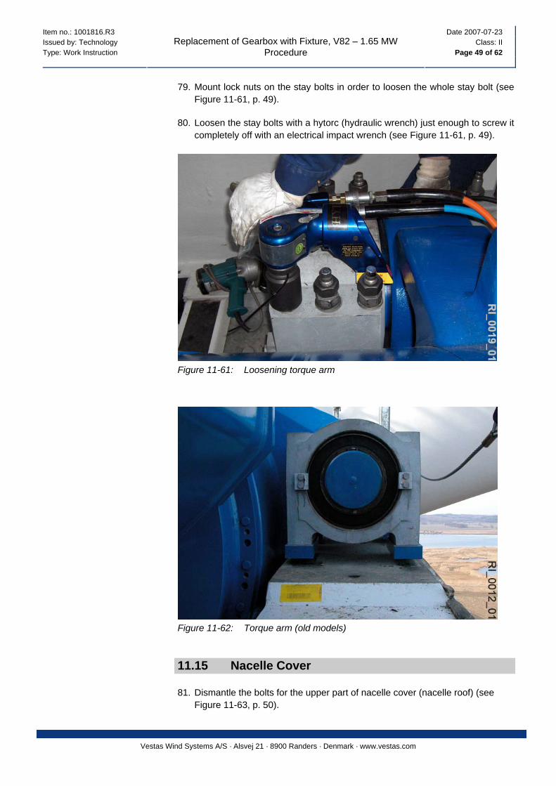
79. Mount lock nuts on the stay bolts in order to loosen the whole stay bolt (see Figure 11-61, p. 49).
80. Loosen the stay bolts with a hytorc (hydraulic wrench) just enough to screw it completely off with an electrical impact wrench (see Figure 11-61, p. 49).
Figure 11-61: Loosening torque arm
Figure 11-62: Torque arm (old models)
11.15 Nacelle Cover
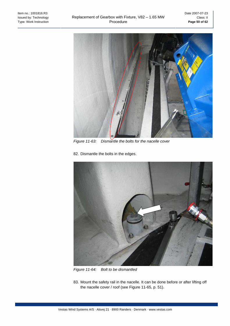
81. Dismantle the bolts for the upper part of nacelle cover (nacelle roof) (see Figure 11-63, p. 50).
Item no.: 1001816.R3 Date 2007-07-23 Issued by: Technology Class: II Type: Work Instruction Page 50 of 62
Replacement of Gearbox with Fixture, V82 – 1.65 MW Procedure
Vestas Wind Systems A/S · Alsvej 21 · 8900 Randers · Denmark · www.vestas.com
Figure 11-63: Dismantle the bolts for the nacelle cover
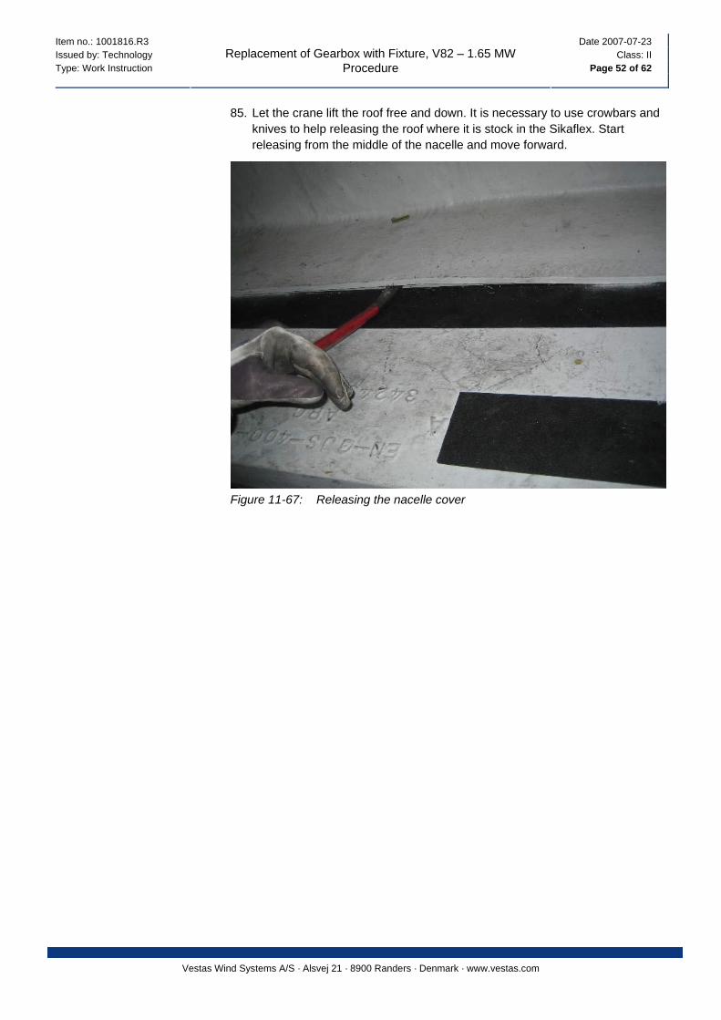
82. Dismantle the bolts in the edges.
Figure 11-64: Bolt to be dismantled
83. Mount the safety rail in the nacelle. It can be done before or after lifting off
the nacelle cover / roof (see Figure 11-65, p. 51).

Item no.: 1001816.R3 Date 2007-07-23 Issued by: Technology Class: II Type: Work Instruction Page 51 of 62
Replacement of Gearbox with Fixture, V82 – 1.65 MW Procedure
Vestas Wind Systems A/S · Alsvej 21 · 8900 Randers · Denmark · www.vestas.com
Figure 11-65: Safety railing mounted
Crushing by falling load
Danger to life due to a falling load if e.g. a lifting chain brakes.
Never stand under a suspended load.
Use only lifting equipment designed for the task. If replacing spare parts for lifting equipment, use only original parts authorised by Vestas.
Always wear safety helmets with chain straps when the overhead crane is in operation.
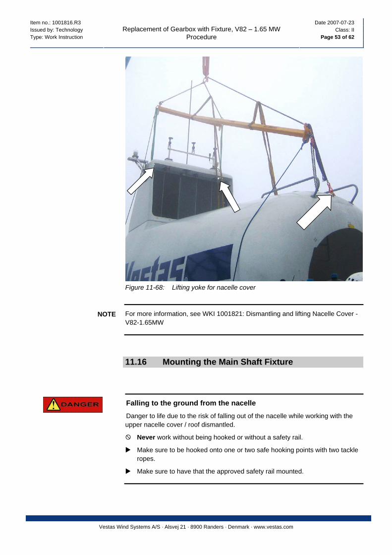
84. Hook on the lifting yoke for the nacelle cover.
Figure 11-66: Lifting the nacelle cover in the radiators
Item no.: 1001816.R3 Date 2007-07-23 Issued by: Technology Class: II Type: Work Instruction Page 52 of 62
Replacement of Gearbox with Fixture, V82 – 1.65 MW Procedure
Vestas Wind Systems A/S · Alsvej 21 · 8900 Randers · Denmark · www.vestas.com
85. Let the crane lift the roof free and down. It is necessary to use crowbars and knives to help releasing the roof where it is stock in the Sikaflex. Start releasing from the middle of the nacelle and move forward.
Figure 11-67: Releasing the nacelle cover
Item no.: 1001816.R3 Date 2007-07-23 Issued by: Technology Class: II Type: Work Instruction Page 53 of 62
Replacement of Gearbox with Fixture, V82 – 1.65 MW Procedure
Vestas Wind Systems A/S · Alsvej 21 · 8900 Randers · Denmark · www.vestas.com
Figure 11-68: Lifting yoke for nacelle cover
For more information, see WKI 1001821: Dismantling and lifting Nacelle Cover - V82-1.65MW
NOTE
11.16 Mounting the Main Shaft Fixture
Falling to the ground from the nacelle
Danger to life due to the risk of falling out of the nacelle while working with the upper nacelle cover / roof dismantled.
Never work without being hooked or without a safety rail.
Make sure to be hooked onto one or two safe hooking points with two tackle ropes.
Make sure to have that the approved safety rail mounted.
Item no.: 1001816.R3 Date 2007-07-23 Issued by: Technology Class: II Type: Work Instruction Page 54 of 62
Replacement of Gearbox with Fixture, V82 – 1.65 MW Procedure
Vestas Wind Systems A/S · Alsvej 21 · 8900 Randers · Denmark · www.vestas.com
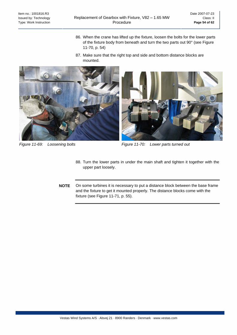
86. When the crane has lifted up the fixture, loosen the bolts for the lower parts of the fixture body from beneath and turn the two parts out 90° (see Figure 11-70, p. 54)
87. Make sure that the right top and side and bottom distance blocks are mounted.
Figure 11-69: Loosening bolts Figure 11-70: Lower parts turned out
88. Turn the lower parts in under the main shaft and tighten it together with the upper part loosely.
On some turbines it is necessary to put a distance block between the base frame and the fixture to get it mounted properly. The distance blocks come with the fixture (see Figure 11-71, p. 55).
NOTE
Item no.: 1001816.R3 Date 2007-07-23 Issued by: Technology Class: II Type: Work Instruction Page 55 of 62
Replacement of Gearbox with Fixture, V82 – 1.65 MW Procedure
Vestas Wind Systems A/S · Alsvej 21 · 8900 Randers · Denmark · www.vestas.com
3
1
2 5
4
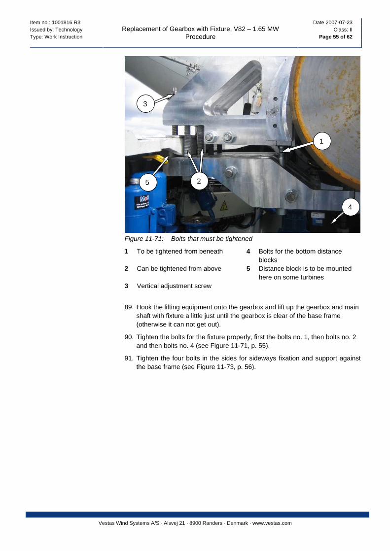
Figure 11-71: Bolts that must be tightened
1 To be tightened from beneath 4 Bolts for the bottom distance blocks
2 Can be tightened from above 5 Distance block is to be mounted here on some turbines
3 Vertical adjustment screw
89. Hook the lifting equipment onto the gearbox and lift up the gearbox and main shaft with fixture a little just until the gearbox is clear of the base frame (otherwise it can not get out).
90. Tighten the bolts for the fixture properly, first the bolts no. 1, then bolts no. 2 and then bolts no. 4 (see Figure 11-71, p. 55).
91. Tighten the four bolts in the sides for sideways fixation and support against the base frame (see Figure 11-73, p. 56).
Item no.: 1001816.R3 Date 2007-07-23 Issued by: Technology Class: II Type: Work Instruction Page 56 of 62
Replacement of Gearbox with Fixture, V82 – 1.65 MW Procedure
Vestas Wind Systems A/S · Alsvej 21 · 8900 Randers · Denmark · www.vestas.com
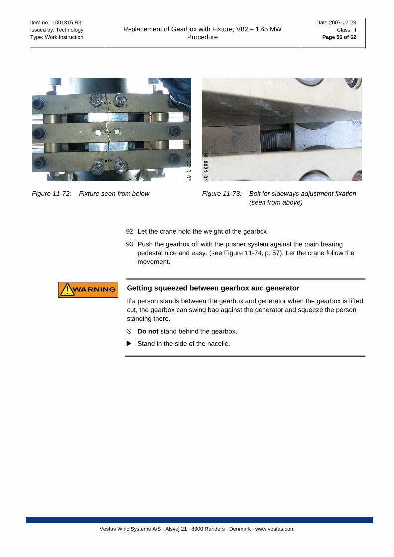
Figure 11-72: Fixture seen from below Figure 11-73: Bolt for sideways adjustment fixation (seen from above)
92. Let the crane hold the weight of the gearbox
93. Push the gearbox off with the pusher system against the main bearing pedestal nice and easy. (see Figure 11-74, p. 57). Let the crane follow the movement.
Getting squeezed between gearbox and generator
If a person stands between the gearbox and generator when the gearbox is lifted out, the gearbox can swing bag against the generator and squeeze the person standing there.
Do not stand behind the gearbox.
Stand in the side of the nacelle.
Item no.: 1001816.R3 Date 2007-07-23 Issued by: Technology Class: II Type: Work Instruction Page 57 of 62
Replacement of Gearbox with Fixture, V82 – 1.65 MW Procedure
Vestas Wind Systems A/S · Alsvej 21 · 8900 Randers · Denmark · www.vestas.com
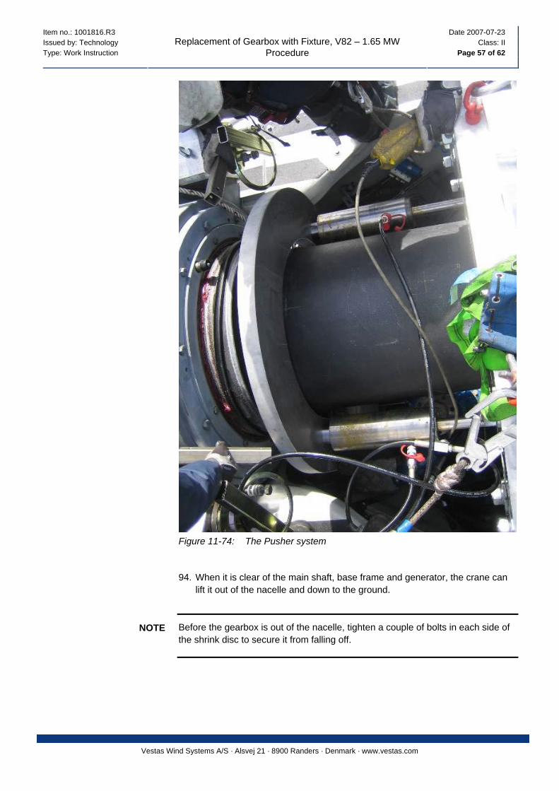
Figure 11-74: The Pusher system
94. When it is clear of the main shaft, base frame and generator, the crane can lift it out of the nacelle and down to the ground.
Before the gearbox is out of the nacelle, tighten a couple of bolts in each side of the shrink disc to secure it from falling off.
NOTE
Item no.: 1001816.R3 Date 2007-07-23 Issued by: Technology Class: II Type: Work Instruction Page 58 of 62
Replacement of Gearbox with Fixture, V82 – 1.65 MW Procedure
Vestas Wind Systems A/S · Alsvej 21 · 8900 Randers · Denmark · www.vestas.com
11.17 Preparing the New Gearbox
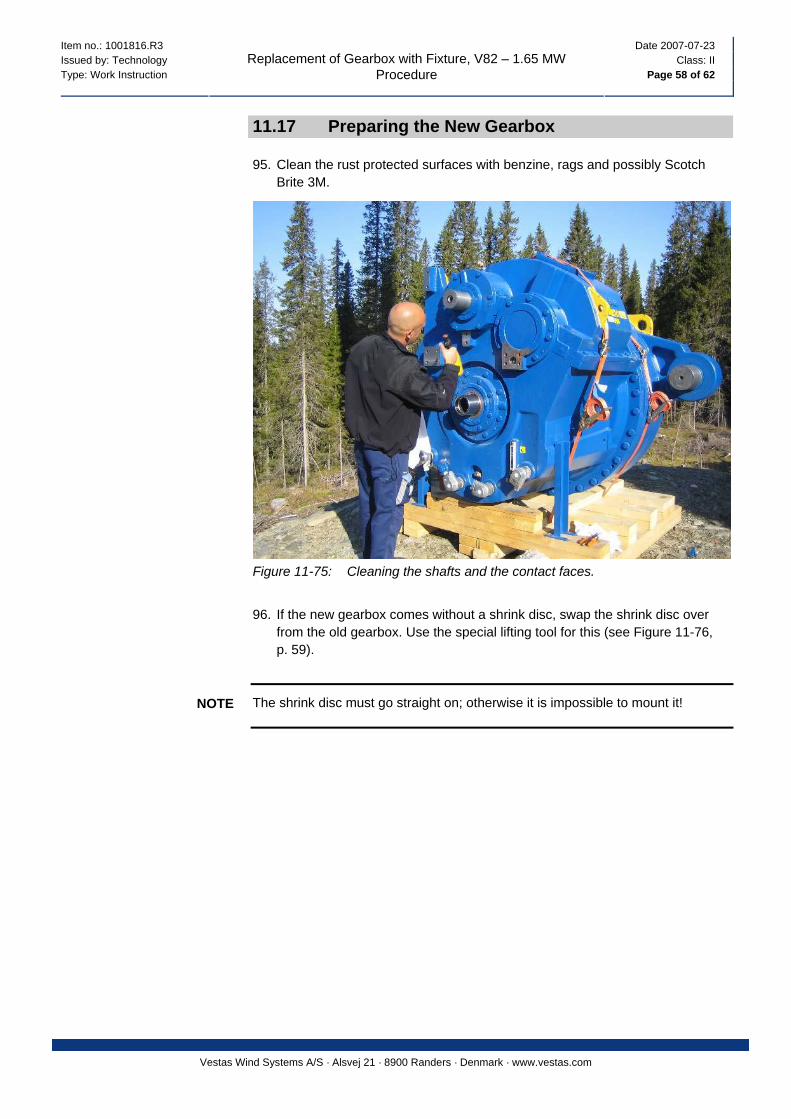
95. Clean the rust protected surfaces with benzine, rags and possibly Scotch Brite 3M.
Figure 11-75: Cleaning the shafts and the contact faces.
96. If the new gearbox comes without a shrink disc, swap the shrink disc over
from the old gearbox. Use the special lifting tool for this (see Figure 11-76, p. 59).
The shrink disc must go straight on; otherwise it is impossible to mount it! NOTE

Item no.: 1001816.R3 Date 2007-07-23 Issued by: Technology Class: II Type: Work Instruction Page 59 of 62
Replacement of Gearbox with Fixture, V82 – 1.65 MW Procedure
Vestas Wind Systems A/S · Alsvej 21 · 8900 Randers · Denmark · www.vestas.com
Figure 11-76: Shrink disc being mounted
97. Mount the shrink element for the brake disc and the brake disc if the new gearbox is not with premounted brake disc. Tighten to the right torque setting according to I&S data.
98. Mount the anchor plate with the brake calibre arrangement.
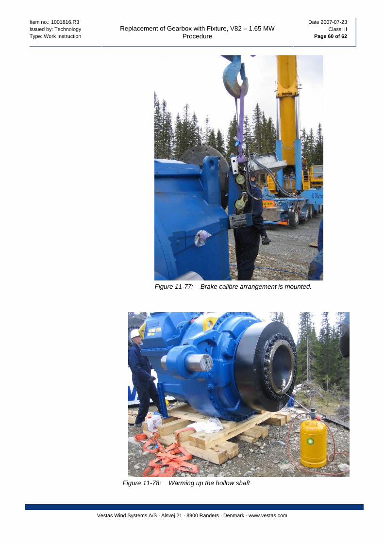
Item no.: 1001816.R3 Date 2007-07-23 Issued by: Technology Class: II Type: Work Instruction Page 60 of 62
Replacement of Gearbox with Fixture, V82 – 1.65 MW Procedure
Vestas Wind Systems A/S · Alsvej 21 · 8900 Randers · Denmark · www.vestas.com
Figure 11-77: Brake calibre arrangement is mounted.
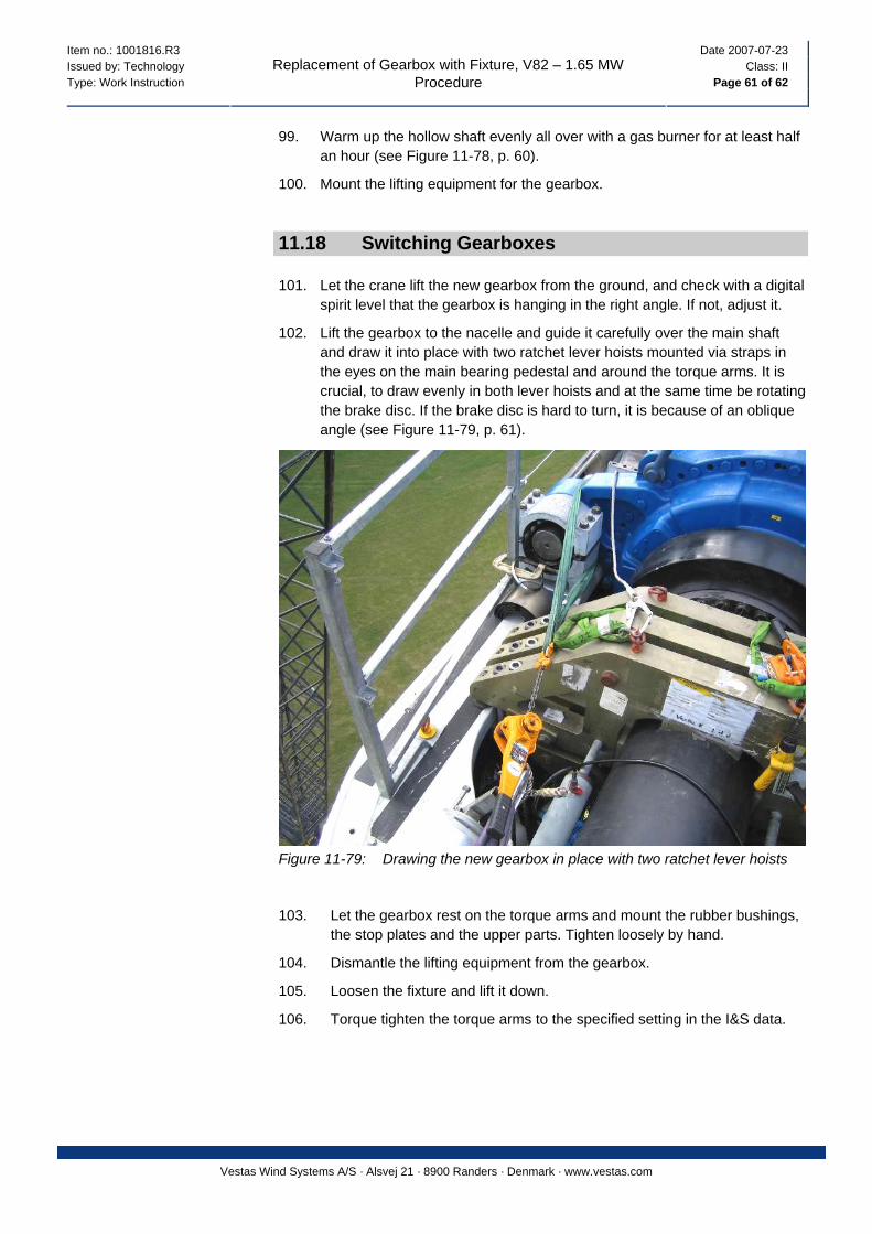
Figure 11-78: Warming up the hollow shaft
Item no.: 1001816.R3 Date 2007-07-23 Issued by: Technology Class: II Type: Work Instruction Page 61 of 62
Replacement of Gearbox with Fixture, V82 – 1.65 MW Procedure
Vestas Wind Systems A/S · Alsvej 21 · 8900 Randers · Denmark · www.vestas.com
99. Warm up the hollow shaft evenly all over with a gas burner for at least half an hour (see Figure 11-78, p. 60).
100. Mount the lifting equipment for the gearbox.
11.18 Switching Gearboxes
101. Let the crane lift the new gearbox from the ground, and check with a digital spirit level that the gearbox is hanging in the right angle. If not, adjust it.
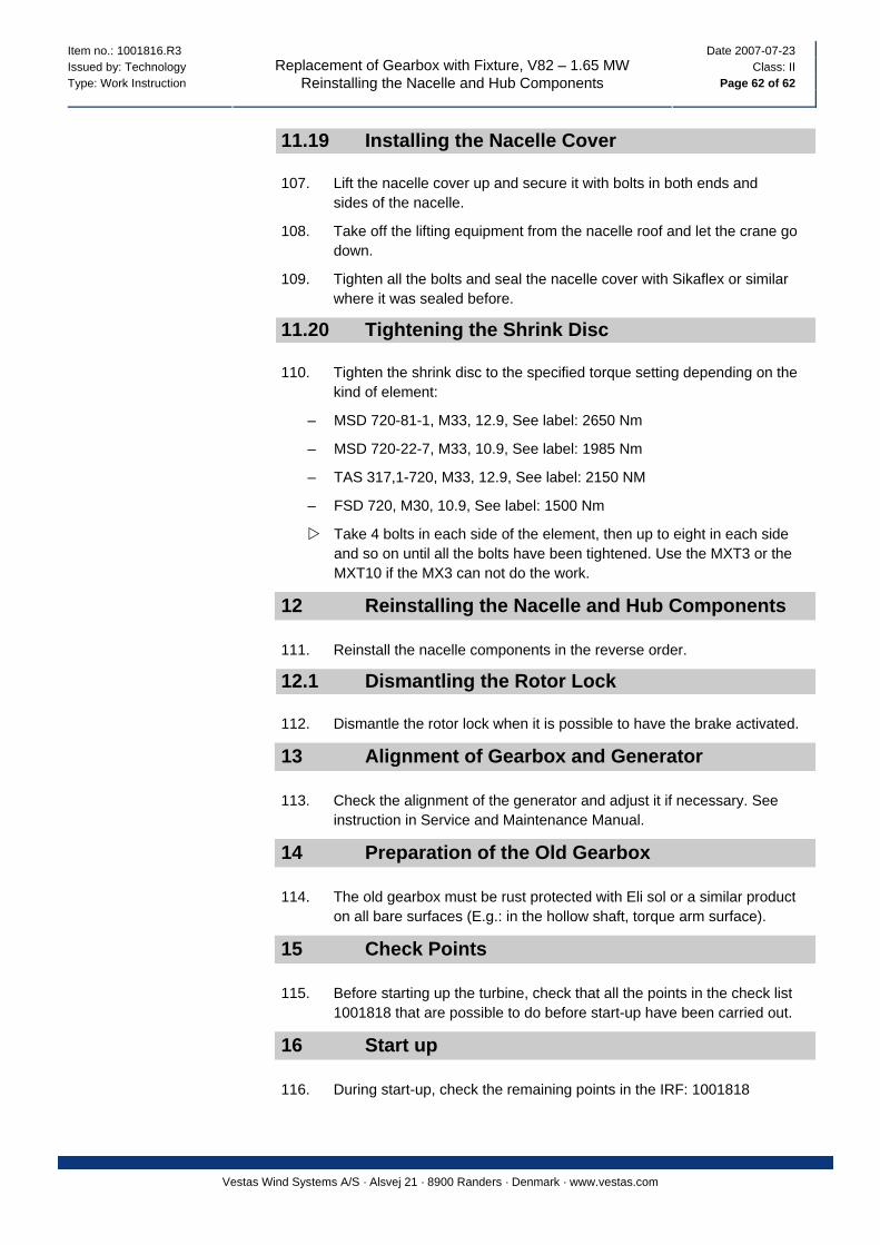
102. Lift the gearbox to the nacelle and guide it carefully over the main shaft and draw it into place with two ratchet lever hoists mounted via straps in the eyes on the main bearing pedestal and around the torque arms. It is crucial, to draw evenly in both lever hoists and at the same time be rotating the brake disc. If the brake disc is hard to turn, it is because of an oblique angle (see Figure 11-79, p. 61).
Figure 11-79: Drawing the new gearbox in place with two ratchet lever hoists
103. Let the gearbox rest on the torque arms and mount the rubber bushings, the stop plates and the upper parts. Tighten loosely by hand.
104. Dismantle the lifting equipment from the gearbox.
105. Loosen the fixture and lift it down.
106. Torque tighten the torque arms to the specified setting in the I&S data.
Item no.: 1001816.R3 Date 2007-07-23 Issued by: Technology Class: II Type: Work Instruction Page 62 of 62
Replacement of Gearbox with Fixture, V82 – 1.65 MW Reinstalling the Nacelle and Hub Components
Vestas Wind Systems A/S · Alsvej 21 · 8900 Randers · Denmark · www.vestas.com
11.19 Installing the Nacelle Cover
107. Lift the nacelle cover up and secure it with bolts in both ends and sides of the nacelle.
108. Take off the lifting equipment from the nacelle roof and let the crane go down.
109. Tighten all the bolts and seal the nacelle cover with Sikaflex or similar where it was sealed before.
11.20 Tightening the Shrink Disc
110. Tighten the shrink disc to the specified torque setting depending on the kind of element:
– MSD 720-81-1, M33, 12.9, See label: 2650 Nm
– MSD 720-22-7, M33, 10.9, See label: 1985 Nm
– TAS 317,1-720, M33, 12.9, See label: 2150 NM
– FSD 720, M30, 10.9, See label: 1500 Nm
Take 4 bolts in each side of the element, then up to eight in each side and so on until all the bolts have been tightened. Use the MXT3 or the MXT10 if the MX3 can not do the work.
12 Reinstalling the Nacelle and Hub Components
111. Reinstall the nacelle components in the reverse order.
12.1 Dismantling the Rotor Lock
112. Dismantle the rotor lock when it is possible to have the brake activated.
13 Alignment of Gearbox and Generator
113. Check the alignment of the generator and adjust it if necessary. See instruction in Service and Maintenance Manual.
14 Preparation of the Old Gearbox
114. The old gearbox must be rust protected with Eli sol or a similar product on all bare surfaces (E.g.: in the hollow shaft, torque arm surface).
15 Check Points
115. Before starting up the turbine, check that all the points in the check list 1001818 that are possible to do before start-up have been carried out.
16 Start up
116. During start-up, check the remaining points in the IRF: 1001818