va enterprise design patterns: cloud computing … enterprise design patterns: cloud computing...
TRANSCRIPT

VA Enterprise Design Patterns:
Cloud Computing
Microservices
Office of Technology Strategies (TS)
Architecture, Strategy, and Design (ASD)
Office of Information and Technology (OI&T)
Version 1.0
Date Issued: July 2016

THIS PAGE INTENTIONALLY LEFT BLANK FOR PRINTING PURPOSES

APPROVAL COORDINATION
___________________________________________
Gary Marshall Director, Technology Strategies, ASD ___________________________________________
Paul A. Tibbits, M.D. DCIO Architecture, Strategy, and Design

REVISION HISTORY
Version Date Organization Notes
0.1 3/11/2016 ASD TS Initial Draft/Outline
0.3 3/29/2016 ASD TS
Second draft document with updates made throughout document based upon initial internal/external stakeholder review and comment.
0.5 5/9/2016 ASD TS
Updated draft for community review prior to TS leadership approval/signature. Updates made following Public Forum collaborative feedback and working session.
0.7 6/28/2016 ASD TS Updates made following Public Forum collaborative feedback and working session.
1.0 ASD TS
Final version for TS leadership approval and signature, including all applicable updates addressing stakeholder feedback and Section 508 Compliance.
REVISION HISTORY APPROVALS
Version Date Approver Role
0.1 3/11/2016 Nick Bogden Enterprise Design Pattern Lead
0.3 3/29/2016 Nick Bogden Enterprise Design Pattern Lead
0.5 3/29/2016 Nick Bogden Enterprise Design Pattern Lead
0.7 6/28/2016 Nick Bogden Enterprise Design Pattern Lead
1.0 Nick Bogden Enterprise Design Pattern Lead

Page i
TABLE OF CONTENTS
1 INTRODUCTION ............................................................................................................................................. 3
1.1 BUSINESS PROBLEM ........................................................................................................................................... 3
1.2 BUSINESS NEED ................................................................................................................................................ 3
1.3 BUSINESS CASE ................................................................................................................................................. 3
1.4 APPROACH ....................................................................................................................................................... 4
2 CURRENT CAPABILITIES ................................................................................................................................. 5
2.1 LIMITED AGILITY ............................................................................................................................................... 5
2.1.1 SDLC ......................................................................................................................................................... 5
2.1.2 Tight Coupling .......................................................................................................................................... 5
2.1.3 Development and Operations .................................................................................................................. 6
2.2 TECHNOLOGY LOCK-IN ....................................................................................................................................... 6
2.3 IT INFRASTRUCTURE EVOLUTION .......................................................................................................................... 7
2.4 MICROSERVICES PROJECTS .................................................................................................................................. 9
3 FUTURE CAPABILITIES .................................................................................................................................... 9
3.1 MICROSERVICES PROJECT EVALUATION CRITERIA..................................................................................................... 9
3.2 MICROSERVICES DESIGN CONSIDERATIONS .......................................................................................................... 11
3.2.1 Decomposition of Business Requirements ............................................................................................. 11
3.2.2 Decomposition of VA Legacy Systems .................................................................................................... 11
3.2.3 Monitoring Services ............................................................................................................................... 12
3.2.4 Stateful vs. Stateless Design .................................................................................................................. 12
3.2.5 Designing for Failure .............................................................................................................................. 13
3.2.6 Container Standardization ..................................................................................................................... 14
3.3 ASSESSING TOOLS TO UTILIZE MICROSERVICES ...................................................................................................... 14
3.3.1 Containers-as-a-Service (CaaS) .............................................................................................................. 14
3.3.2 Microservices Testing ............................................................................................................................. 15
3.3.3 Secure Registry ....................................................................................................................................... 16
3.3.4 Management Capabilities ...................................................................................................................... 16
3.3.5 Microservices and Container Workflow ................................................................................................. 17
3.4 SUMMARY OF PRINCIPLES ................................................................................................................................. 18
3.5 MICROSERVICES RISKS ...................................................................................................................................... 18
3.6 ALIGNMENT TO TRM ....................................................................................................................................... 19
3.7 ALIGNMENT TO VETERAN-FOCUSED INTEGRATION PROCESS (VIP) ............................................................................ 20
4 USE CASES ................................................................................................................................................... 20
4.1 USE CASE #1 – GREENFIELD DEVELOPMENT ......................................................................................................... 20
4.2 USE CASE #2 – BROWNFIELD DEVELOPMENT ....................................................................................................... 22
APPENDIX A. DOCUMENT SCOPE ......................................................................................................................... 25
APPENDIX B. DEFINITIONS ................................................................................................................................... 26
APPENDIX C. ACRONYMS ..................................................................................................................................... 27
APPENDIX D. REFERENCES, STANDARDS, AND POLICIES ...................................................................................... 29

Page ii
FIGURES
Figure 1 - “As-Is” eMI Architecture ............................................................................................................... 8
Figure 2 - Microservice Evaluation Criteria ................................................................................................. 10
Figure 3 - Microservices Testing Pyramid ................................................................................................... 15
Figure 4 - “To-Be” Microservices and CaaS Workflow ................................................................................ 18
Figure 5 - Use Case #1 ................................................................................................................................. 21
Figure 6 - Use Case #2 ................................................................................................................................. 23
TABLES
Table 1 - Summary of Principles.................................................................................................................. 18
Table 2 - Microservice Adoption Risks ........................................................................................................ 19
Table 3 - TRM Approved Standards and Technologies ............................................................................... 19
Table 4 - Acronyms...................................................................................................................................... 27
Table 5 - References, Standards, and Policies ............................................................................................ 29

Page 3
1 INTRODUCTION
1.1 BUSINESS PROBLEM
The majority of existing Veterans Affairs (VA) applications consist of full-stack, monolithic
architectures with limited flexibility to changing business needs. Monolithic applications
present the following challenges:
1. Limited agility – Continuous deployment is difficult, forcing developers to redeploy the entire application (e.g. WAR files) in order to update one component
2. Technology lock-in – Changes cannot be made to part of the application code, meaning all of it has to be modified
3. IT infrastructure evolution – Decomposition of monolithic applications into microservices is inhibited by limited availability of Commercial-off-the-shelf (COTS) platforms to perform networking and orchestration
Many existing VA software solutions were built using traditional waterfall approaches. The
sequential nature of the waterfall approach presents challenges to rapidly changing business
needs and reduced development timeframes.
1.2 BUSINESS NEED
With the adoption of cloud-native DevOps and the need to deliver IT capabilities in an
expedited manner, monolithic applications present challenges to keeping up with rapidly
changing business needs. For example, a monolithic application has presentation, business, and
data logic located in a single, logical package that is deployed in resource-intensive application
servers. Minor changes to part of the architecture require testing and redeployment of the
entire package. Software systems developed in a monolithic fashion do not have the flexibility
to modify or add new features without a re-design of the whole application.
1.3 BUSINESS CASE
Microservices address the limitations of monolithic architectures. To help standardize
microservice architectures at VA, this Enterprise Design Pattern (EDP) provides a VA-specific
definition for microservices. A microservice provides a single business function with the
following characteristics:
Fine-grained: Encompasses a specific service component that delivers an individual business capability (e.g. provide current patient prescriptions)
Loosely coupled: Functions with little or no knowledge of other business functions; thereby limiting or removing the impact of changes made to one business function on other functions with which it interfaces with

Page 4
Independently deployable: Can be used by multiple applications or systems; self-contained by running its own isolated processes and computations
Vendor-neutral: Leverages open standards for inter-process communication (e.g. HTTP) with other services
Service Oriented Architecture (SOA), as defined in the SOA Enterprise Design Pattern, provides
a framework of general design principles for services, while microservices represent an
implementation of that framework for specific services. For the context of this document,
microservices are best described as “fine-grained SOA” consistent with industry best practices
for DevOps.
VA has begun to address the challenges of rapidly changing business needs and reduced
development timeframes by embracing agile software development practices with its
continued emphasis on consolidating IT infrastructure and use of enterprise IT services,
including Enterprise Shared Services (ESS) and cloud-based solutions. In concert with these
changes, VA will adopt a microservices architectural style leveraging agile development
techniques for both existing and new software projects.
1.4 APPROACH
The near-term approach to incorporate microservices into existing and future VA software
systems is as follows:
1. Determine enterprise standard criteria for microservices approach a. Criteria for using microservices for new applications (Greenfield) b. Criteria for functional decomposition of legacy systems or integration of new
applications with legacy systems (Brownfield) 2. Disseminate criteria to project teams for review prior to first project decision review 3. Re-evaluate criteria through lessons learned from previous microservice enabled
projects
Performed concurrently with 1 and 2 above:
4. Conduct market research on COTS platforms (including open-source) for supporting a microservices architecture
5. Acquire and deploy COTS platforms for use in the DevOps community 6. Include approved COTS platforms in Technical Reference Model (TRM) 7. Direct usage of COTS platforms through the TRM 8. Re-evaluate product usage through lessons learned from previous microservice enabled
projects

Page 5
2 CURRENT CAPABILITIES
VA’s current monolithic architecture encompasses a waterfall software development life cycle
(SDLC), tight coupling of systems, segmented development and operations, vendor lock-in, and
large SOA infrastructure services. It also includes an enterprise service bus (ESB), which focuses
more on the central infrastructure than the application itself. These issues are addressed
further in the following sub-sections.
2.1 LIMITED AGILITY
2.1.1 SDLC
Capabilities: VA application development is categorized as in-house or through contractors. In-
house and contractor application development was traditionally developed using a waterfall or
incremental SDLC. For example, within Veterans Health Administration (VHA), contractors
typically develop critical applications. Contractor-developed and in-house applications have the
option of utilizing their own environment or VA’s development environment (i.e. Mobile
Application Environment). Either event requires the final application to be uploaded to the VA
environment for compliance review.
VA has recently revamped the IT delivery framework, which follows a lean-agile framework,
bringing greater agility to VA’s SDLC (see Section 3.7). VA is transitioning to the agile software
development environment and has initiated pilot software projects that are diverse in terms of
scope, size/complexity, customers, and stages in the project lifecycle.
Limitation(s): A combination of factors, including the agile initiatives and the enterprise-cloud
migration, calls for SDLC that can provide timely business value to VA and occur in an efficient
manner. Adhering to the new framework helps VA transition to an agile environment capable of
handling changing business needs. While VA has a new IT delivery framework in place, the
limitations associated with the previous framework still exist. The new IT delivery framework
only addresses future projects.
2.1.2 Tight Coupling
Capabilities: Many of the existing VA applications require a high level of interdependence in
order to function properly. The complexity to build new capabilities or address existing issues in
operational systems is significant due to these interdependencies. For instance, the VistA
Access Enhancements (VAE) team has described their effort as a “complex environment, with
many moving pieces.”
Limitation(s): Traditional monolithic design amplifies and enhances the coupling of systems. A
higher degree of coupling leads to increased challenges in extending or making changes to an
existing system. The problems are exacerbated as the systems become larger. As a result the

Page 6
easiest way to extend tightly coupled systems is to incorporate even more interdependence
among the systems. In a tightly coupled architecture, the high interdependence of systems can
lead to a single point of failure that can potentially crash the whole system.
Capabilities: Library sharing is a good design approach to modularize different domains into
separate libraries. This allows application code that fall under a common domain to share code
libraries. This is done within systems and among systems at VA.
Limitation(s): While shared libraries are not incompatible with a service-based approach it does
not provide many of the benefits of microservices. Using a different language or platform is
difficult when libraries are used as the only form of modularization. This practice limits
solutions for specific domains, does not enable the advantages of process isolation, and cannot
scale independently as load requires. Shared libraries also mean shared or planned releases,
which creates dependencies on process releases across teams.
2.1.3 Development and Operations
Capabilities: Development, operations, and quality assurance of VA applications is segmented.
This is apparent across VA Lines of Business (LOBs), including the Veterans Benefits
Administration (VBA). As part of the DevOps/Benefits Transformation, a study was performed
to identify existing challenges with VBA’s SDLC. VBA discovered differences in the development
and operations environments that caused failures, affecting the Veteran’s ability to access VA
services and benefits.1 Once an application is released there is only a three-month support
period from the development team. After this period, all maintenance and operation becomes
the responsibility of the business owner of the application.
Limitation(s): The VA IT ecosystem consists of multiple systems and teams that do not always
coordinate together. The current segmented nature prevents an enterprise that integrates
development, deployment, and oversight to ensure efficient use of resources.
Large software project development teams working with monolithic architectures encounter
inefficiencies as the software is not designed in a modular fashion. It inhibits developers to
work concurrently on a common component.
2.2 TECHNOLOGY LOCK-IN
Capabilities: The VA development tools and integrated development environments (IDEs) are
geared toward single application development guided by monolithic architectures. Since
1VA. (2013) Business Requirement Session (DEVOPS/Benefits Transformation)

Page 7
monolithic architectures are tightly coupled, any changes made to one part of the architecture
affects the entire application. This makes it difficult to utilize different technologies that are
better suited for the job when making changes or updates to an existing application.
Limitation(s): Monolithic applications often cannot scale with changes to size and complexity
and therefore are not aligned with VA’s transition towards agile development. Usually,
incorporating changes to one part of the architecture requires a redesign or update to the
entire architecture. As a result, updating the application with a new framework would require a
redesign, potential schedule delays, or increased cost. Therefore, VA would be committed
strictly to the technology decisions made in the initial stages of the lifecycle.
2.3 IT INFRASTRUCTURE EVOLUTION
Capabilities: The Enterprise Messaging Infrastructure (eMI) delivers customized COTS suite of
tools to provide a reliable, secure, high-performance, and globally scalable SOA information
exchange system. As the official SOA infrastructure backbone for ESS per the (Enterprise
Architecture) Enterprise SOA EDP, all projects are mandated to use eMI for integration with
ESS. The eMI delivers a network-centric infrastructure that enhances service delivery and
security, allowing VA to efficiently share and communicate information. The “As-Is”
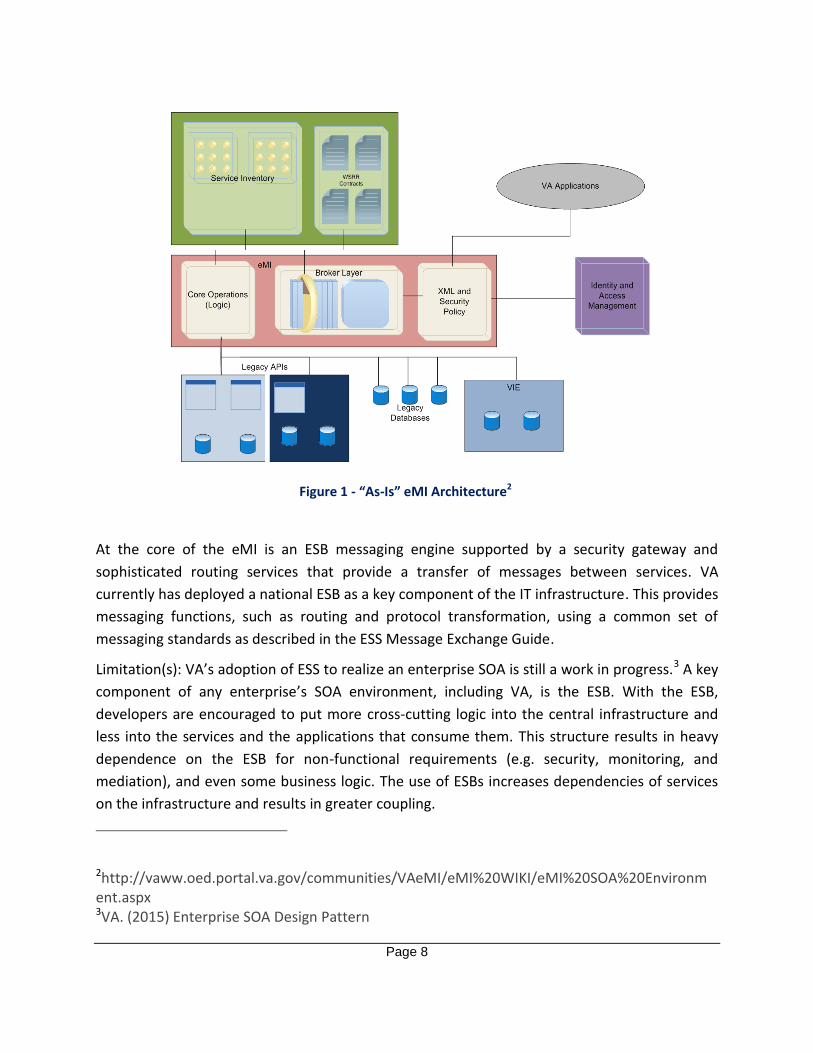
architecture for eMI consists of several key components depicted in Figure 1.
Page 8
Figure 1 - “As-Is” eMI Architecture2
At the core of the eMI is an ESB messaging engine supported by a security gateway and
sophisticated routing services that provide a transfer of messages between services. VA
currently has deployed a national ESB as a key component of the IT infrastructure. This provides
messaging functions, such as routing and protocol transformation, using a common set of
messaging standards as described in the ESS Message Exchange Guide.
Limitation(s): VA’s adoption of ESS to realize an enterprise SOA is still a work in progress.3 A key
component of any enterprise’s SOA environment, including VA, is the ESB. With the ESB,
developers are encouraged to put more cross-cutting logic into the central infrastructure and
less into the services and the applications that consume them. This structure results in heavy
dependence on the ESB for non-functional requirements (e.g. security, monitoring, and
mediation), and even some business logic. The use of ESBs increases dependencies of services
on the infrastructure and results in greater coupling.
2http://vaww.oed.portal.va.gov/communities/VAeMI/eMI%20WIKI/eMI%20SOA%20Environment.aspx 3VA. (2015) Enterprise SOA Design Pattern

Page 9
2.4 MICROSERVICES PROJECTS
VA has a limited number of projects in the design phase that propose utilizing microservices
architecture. These projects include the Enterprise Health Management Platform (eHMP)
Clinical Practice Environment - VistA Exchange and Application Programming Interface (API) 2.0
projects that are part of the VistA Evolution program.4,5 These projects, along with the guidance
from this document, will help establish the use of microservices for future VA projects.
3 FUTURE CAPABILITIES
This section contains guidelines for when to implement microservices architecture and
recommendations for how to do so. The future state of VA will enable the use of microservices
to promote agile methodologies, avoid technology lock-in, and incorporate more business logic
into the application, instead of the infrastructure. Guidance and recommendations mostly
originate from industry best practices.
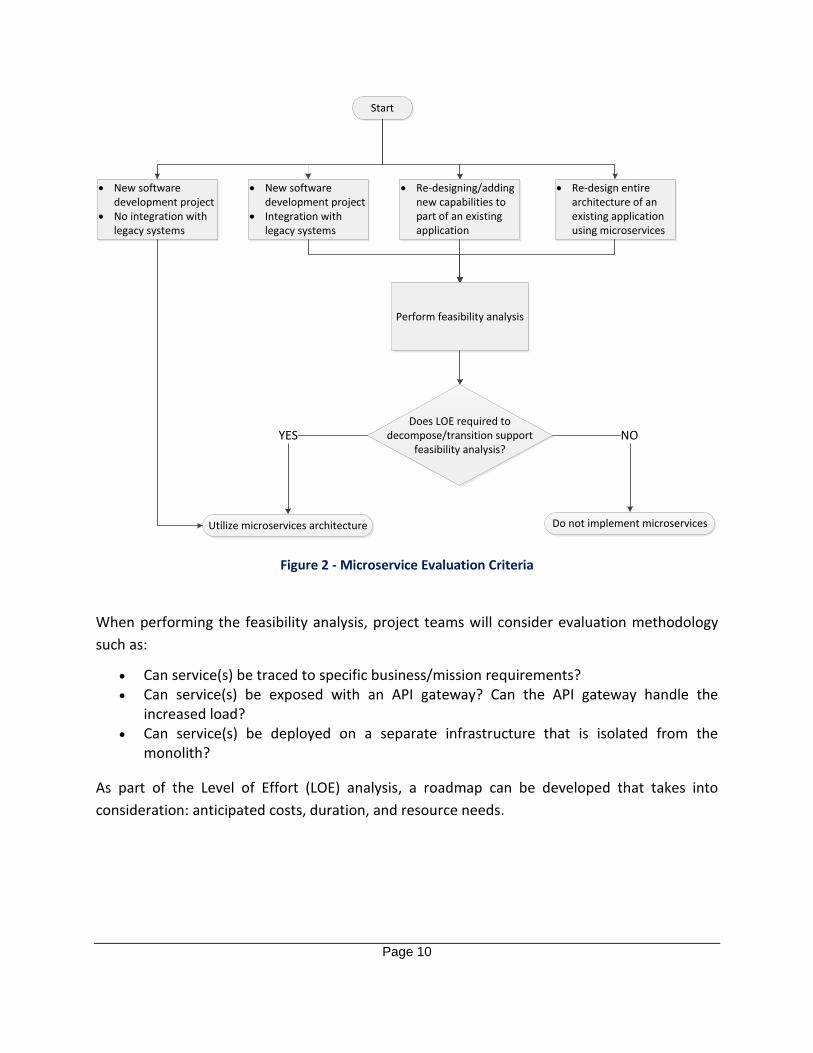
3.1 MICROSERVICES PROJECT EVALUATION CRITERIA
The following flow chart helps guide the project team on whether to implement microservices
or not.
4VA. (2014) eHMP System Design Document Increment 1 and 2 5VA. (2015) VistA API 2.0 CDO Design Pattern Analysis and Recommendation
Page 10
New software development project
No integration with legacy systems
Start
Re-designing/adding new capabilities to part of an existing application
Utilize microservices architecture
Re-design entire architecture of an existing application using microservices
Do not implement microservices
YES NO
New software development project
Integration with legacy systems
Perform feasibility analysis
Does LOE required to decompose/transition support
feasibility analysis?
Figure 2 - Microservice Evaluation Criteria
When performing the feasibility analysis, project teams will consider evaluation methodology
such as:
Can service(s) be traced to specific business/mission requirements?
Can service(s) be exposed with an API gateway? Can the API gateway handle the increased load?
Can service(s) be deployed on a separate infrastructure that is isolated from the monolith?
As part of the Level of Effort (LOE) analysis, a roadmap can be developed that takes into
consideration: anticipated costs, duration, and resource needs.

Page 11
3.2 MICROSERVICES DESIGN CONSIDERATIONS
3.2.1 Decomposition of Business Requirements
For new application development, service profiling should be used as a method for architecting
a microservice solution. Service profiling refers to the initial phase of the microservices design
process where project teams decompose services that will be offered and assembled. Project
teams will identify which new services are to be built and ensure that these applications
strongly align to documented and approved business use cases as well as the existing VA
enterprise architecture. Focusing on the mission alignment at the start of the lifecycle enables
VA teams across different VA departments to synchronize accordingly. This reduces resource
inefficiencies by preventing duplication of work resulting from the lack of communication or
collaboration between VA teams using monolithic architecture approaches.
The following steps describe how to implement a new application centered on the use of
microservices:
1. Project teams break down service needs via enterprise architecture and mission requirements which set standards for the information needed from the service at the atomic or business level
2. Project teams leverage a fine-grained scope at the atomic service level, taking into consideration only the optimal amount of information needed to make the service usable, reusable, portable, and distributable
3. Project teams create a Service Level Agreement (SLA) for the atomic services that specifically states the protocols and functionality the services will provide
4. At the business level, project teams focus on services that require integration of multiple attributes
5. When approaching microservices at the enterprise level, VA organizes technical teams based on what enterprise service needs to be delivered
Utilizing the business needs to identify capabilities suited for microservices helps address the
following problem.
Problem(s) Addressed: Limited Agility
3.2.2 Decomposition of VA Legacy Systems
For monolithic applications where all capabilities are integrated together, the following steps
dictate how to assess and decompose VA legacy systems into re-usable microservices:
1. Determine capabilities from the application that can be separated and moved to separate microservices. The microservice should be designed to be modular and accomplish a single capability to enhance unit testing and performance verification. The following types of capabilities are well suited for microservices, either for legacy systems or new applications:

Page 12
a. User or account information b. Authorization and session management c. Preferences or configuration settings d. Notifications and communications services e. Photos and media, especially metadata
2. Identify service classes which utilize create, retrieve, update, and delete (CRUD) interfaces and business logic layers that do not have dependencies on other classes. The microservices from the service layer expose the data services from the VA data layer. The interfaces of these services are used to perform the CRUD operations on data.
3. Perform re-factoring within legacy codebase and deploy it to production. 4. Define in the SLA, the protocols and functionality the services provide.
The capabilities suited for decomposition of VA legacy systems into microservices help address
the following problem.
Problem(s) Addressed: Limited Agility
3.2.3 Monitoring Services
VA will monitor services, taking into consideration the status and performance of the individual
microservices, while verifying that the whole application meets user expectations. VA will
collect service health reports, and in instances when services are not performing as required,
identify and resolve the impact on scaling. This information will be collected and processed in
accordance with the Data Analytics EDP to improve the performance and identify microservices
that may need redesign. VA will institute an activity monitoring framework capable of tracking
logins across platforms in accordance with the Enterprise Auditing EDP.
Incorporating monitoring of microservices on an individual and collective perspective helps
address the following problems.
Problem(s) Addressed: Limited Agility, IT Infrastructure Evolution
3.2.4 Stateful vs. Stateless Design
When utilizing microservices, it is important to understand which type of design is best suited
for an application. Stateless microservices do not maintain any internal state between requests
and rely on an external data store for data persistence. Stateful microservices maintain an
internal state between requests with an internal data store. Stateless microservices are best
used for web front-ends, protocol gateways, and cloud services, while stateful services are best
for databases, documents, user profiles, and shopping carts. Stateless microservices are more
agile and scalable, minimizing the need to make significant changes or reconfigurations to the
application. However, in instances of data intensive applications, stateful services provide data
locality, which lowers latency and offers better performance. In general, stateless microservices

Page 13
should be utilized whenever possible, however, there are some instances where a stateful
service design is better.
Regardless of the design, each microservice will utilize the VA data layer for its data storage
needs. This can lead to applications that utilize several different data storage types depending
on the microservices utilized and the criteria of the application. The VA data layer provides
access to all of VA’s data storage options. The type of data storage utilized depends primarily on
the following three criteria: data temperature, data structure, and concurrency support. Data
storage options are detailed in the Data Storage EDP.
The combination of stateful and stateless microservices design coupled with the use of the VA
data layer addresses the following problems.
Problem(s) Addressed: Limited Agility, IT Infrastructure Evolution
3.2.5 Designing for Failure
While microservices are designed to be small and well-tested, it is important to design them to
handle failure (i.e. network latency, data centers shutting down, or other microservice failures).
Automatic failure handling techniques, such as the circuit breaker pattern, detect failure and
prevent an application from trying to reiterate an action which is likely to fail.6 A circuit breaker
acts as a discovery service, ensuring that one microservice can identify when another
microservice is down and immediately notify the main circuit breaker. This allows the
microservice to check the circuit breaker of the microservice it is connected to, and determine
if it is broken. If it is broken, the circuit breaker can prevent calls being made to or from that
particular microservice.
Another option is having a central logging microservice, which can receive log messages from
other microservices for inspection and searching, which would be done through a correlation
token created by an API gateway. Regardless of the method, each microservice will have a
method for mitigating unforeseen failures.
By incorporating mechanisms to address microservice failures the following problem is
addressed.
Problem(s) Addressed: Limited Agility
6https://martinfowler.com/bliki/CircuitBreaker.html

Page 14
3.2.6 Container Standardization
As OS-level virtualization container technology is still maturing, it is important for VA to adopt
the standards developed from industry. One organization in particular, the Open Container
Initiative (OCI), is an open governance structure for creating open industry standards around
container formats, container management, and runtime. OCI is leading the effort in container
standardization.7
VA will utilize containers deployed through a commercial Platform-as-a-service (PaaS) provider.
Leveraging a commercial PaaS allows VA to avoid the complexity of building and maintaining
the infrastructure associated with developing and launching an application. Refer to the PaaS
EDP for further information.
By adhering to industry container standards and leveraging commercial PaaS the following
problems are addressed.
Problem(s) Addressed: Limited Agility, Technology Lock-in
3.3 ASSESSING TOOLS TO UTILIZE MICROSERVICES
3.3.1 Containers-as-a-Service (CaaS)
VA requires a CaaS COTS platform approved for use in the Technical Reference Model (TRM).
CaaS addresses the challenges associated with microservices and enables applications to be
distributed on multiple platforms. CaaS also addresses the limitations VA currently encounters
with its monolithic applications.
Agility – Shortens the duration between software release cycles that VA requires by aligning with sprint cycles
Portability – Provides the means to package the application and dependencies together making the container a complete and independent unit, allowing containerized applications to seamlessly transition from the development phase to the testing phase to production
Control – Allows for standardization of the application environment with native tooling to manage the infrastructure and applications’ unifying VA’s heterogeneous set of infrastructure, code bases, and systems
Uses of CaaS address challenges associated with microservices and help address the following
problems.
7https://www.opencontainers.org/

Page 15
Problem(s) Addressed: Limited Agility, Technology Lock-in, IT Infrastructure Evolution
3.3.2 Microservices Testing
When testing microservices, it is important to formulate an effective testing strategy that can
provide support at every layer of testing. A key factor in defining a good test strategy is to
identify the right amount of testing for each point in the test lifecycle. The following diagram
depicts a bottom-up approach of the four phases of testing according to the testing pyramid.8
Figure 3 - Microservices Testing Pyramid
The unit testing phase consists of the largest volume of tests. All tests should be automated,
depending on the development language and framework used in the service. There are two
methods of contract testing. The correct method depends on the end goal of the microservice
and how the interfaces with consumers are defined. The first method is integration contract
testing, where a test double (mock or stub) replicates a service that is to be consumed and
must be verified with the real service to ensure consistency. The other method is consumer-
driven contract testing, where consumers define how they consume the service through
customer contracts.
8Infosys. (2016) White Paper – An Insight into Microservices Testing Strategies

Page 16
The next phase is integration testing, which leverages a testing environment where individual
microservices can be integrated before deployment. VA’s Enterprise Development Environment
(EDE) has developed a test environment referred to as the EDE Azure External Environment.
This environment can be leveraged as a proving ground when building out microservices and
integration testing. End-to-end testing is best served in situations where there is an interface to
an externally-exposed service and the developer of the service provides a testing or "sandbox”
version.
A structured testing framework combined with the use of VA’s testing environment helps
address the following problems.
Problem(s) Addressed: Limited Agility, IT Infrastructure Evolution
3.3.3 Secure Registry
VA will utilize a COTS product for registering microservices, and will include open source
solutions for service discovery. VA will ensure that an open source environment is enabled by
maintaining a consistent container format, regardless of vendor, and eliminating restrictions on
destinations and orchestration layers. VA will make portable microservices applications for the
purposes of maintaining flexibility with the wide portfolio of industry orchestration tools and
selecting the best fit for managing run time. At the deployment phase, VA will share proven
microservices applications throughout the VA infrastructure to promote reuse. In applying
microservices applications across the VA infrastructure, security throughout different
environments is imperative. VA will ensure that data remain isolated between environments for
independent applications. As important, operator-access permissions across teams will be
bounded based on the need to access or collaborate with a corresponding environment.
A registry for secure storage, management, and distribution of microservices helps address the
following issue.
Problem(s) Addressed: IT Infrastructure Evolution
3.3.4 Management Capabilities
VA will employ management capabilities to achieve automation and mitigate downtime of
microservices. VA will receive performance notifications, and when performance is lagging, will
respond with an automated repair process to streamline setup of the microservices. VA will also
leverage automation in the microservices architecture deployment process to ensure accurate
and streamlined testing. VA will implement backwards compatibility along with rolling upgrades
for the purposes of mitigating outages when enhancements are made on the microservices.
Version control of microservices will also need to be instituted.
Page 17
VA will utilize API management for microservices. API management is based on the enterprise
architecture and mission requirements, and regulates the external services that can call the
APIs, the instances which they can call the APIs, and the protocols used to call the APIs. VA will
collect metrics on API usage to identify the source of API calls as well as any occurrence of
latency.
The use of management tools to track performance and manage APIs helps address the
following problems.
Problem(s) Addressed: Limited Agility, IT Infrastructure Evolution
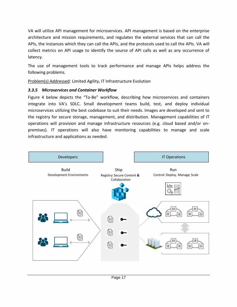
3.3.5 Microservices and Container Workflow
Figure 4 below depicts the “To-Be” workflow, describing how microservices and containers
integrate into VA’s SDLC. Small development teams build, test, and deploy individual
microservices utilizing the best codebase to suit their needs. Images are developed and sent to
the registry for secure storage, management, and distribution. Management capabilities of IT
operations will provision and manage infrastructure resources (e.g. cloud based and/or on-
premises). IT operations will also have monitoring capabilities to manage and scale
infrastructure and applications as needed.
IT OperationsDevelopers
Build Ship RunDevelopment Environments Registry: Secure Content &&
Collaboration
Control: Deploy, Manage, Scale

Page 18
Figure 4 - “To-Be” Microservices and CaaS Workflow
Integrating microservices and CaaS into VA’s SDLC help address the following problems.
Problem(s) Addressed: Limited Agility, Technology Lock-in, IT Infrastructure Evolution
3.4 SUMMARY OF PRINCIPLES
The following table summarizes the six key principles to leverage the full value of microservices.
These guiding principles are applicable to both SOA and microservices.
Table 1 - Summary of Principles
Requirements Description
SLA
The service provider uses the contract to express the purpose of the microservice and its requirements. It is important that VA’s microservices architecture supports different data formats and transportation protocols without re-building services repeatedly.
Exposing microservices from existing applications
VA can either build completely new services or expose parts of existing applications as a microservice. Separating the transport logic from the service logic is a best practice.
Service discovery VA must discover and use other services, to be published via an API gateway. Details of the API gateway are documented in the Secure Messaging EDP.
Coordination across services
Combining services in a higher level logic serve as applications or business processes, proves to be faster to develop and easier to maintain.
Managing complex deployments and scalability
Automation is key for an agile, flexible, and productive microservices environment. It is important to administer and monitor all VA microservices with a central user interface, and to choose a specific scalable, fault-tolerant, performant runtime for VA specific projects.
Visibility across services After deploying and running microservices in production, VA should combine events, context, and insights from different services for instant awareness and event correlation.
3.5 MICROSERVICES RISKS
In addition to the design considerations presented in this section, project teams must also
consider the risks associated with microservices as highlighted in the following table.

Page 19
Table 2 - Microservice Adoption Risks
Risk Description
Migrating data on a live application
Data migration on a live application is situation-dependent and can result in newer data being overwritten with older data.
Performance overhead The gains in code deployment and operation independence from
microservices also bring greater traffic to the network.
More connection points
Load balancing
Firewall and port management at fine-grained level will
be more tedious unless broadly scoped
Multiple message formats impact scanning and inspection.
Data segmentation If improperly designed, microservices can form information barriers.
Developer responsibilities Developers need great understanding and participation in operations and productions. Microservices-based applications are tightly integrated into their environmental contexts.
More interfaces Maintaining the SLAs between microservices is important. A change in syntax or semantics to one side of the contract requires all other services to understand that change.
3.6 ALIGNMENT TO TRM
All components of VA’s “To-Be” microservices architecture will use approved technologies and
standards located in the VA TRM to comply with the architectural guidance provided in this
document. VA will evaluate new technologies, particularly those provided by commercial cloud
service providers, and those approved for enterprise consumption will be catalogued in the
TRM. The following table highlights the standards profile and approved technologies for
microservices.
Table 3 - TRM Approved Standards and Technologies
Tool Category Example Approved Standards and
Technologies
Application Server Software GlassFish, Weblogic Server
Web Server Software Apache Tomcat, IBM HTTP Server
Load and Performance Testing Tools
Apache JMeter

Page 20
System Testing Tools HP Fortify On-Demand
Build and Deployment Tools Docker, Jenkins Continuous Integration Server
Application Development Tools Eclipse WebTools Platform, XML, HL7 API, HTML, JavaScript, Node.js, Swagger
Development Frameworks Java API for RESTful Web Services,
Microsoft .NET Framework, Python
Enterprise Service Bus eMI
Service Registry WebSphere Service Registry and
Repository
SOA Governance CA API Gateway
Load Balancing and Failover EMC PowerPath
Cloud Technologies OpenStack
Virtualization Software Citrix Receiver, Red Hat Enterprise Virtualization, VMWare
3.7 ALIGNMENT TO VETERAN-FOCUSED INTEGRATION PROCESS (VIP)
The Veteran-focused Integration Process (VIP) is a Lean-Agile framework that services the
interest of Veterans through the efficient streamlining of activities that occur within the
enterprise. The VIP framework unifies and streamlines IT delivery oversight, delivering IT
products more efficiently, securely, and predictably. VIP is the follow-on framework from
Project Management Accountability System (PMAS) for the development and management of
IT projects, which will rigorously propel the Department toward Veteran-focused delivery of IT
capabilities.
More information can be found here.
4 USE CASES
The following use cases are examples that demonstrate the application of the capabilities and
recommendations described in this document.
4.1 USE CASE #1 – GREENFIELD DEVELOPMENT
The Greenfield use case describes the high level architecture when microservices are utilized
for new applications. An assessment of the baseline monolithic system is not applicable and
therefore no refactoring or decomposition is required. Technical teams develop and scale the
services independently.
Assumptions

Page 21
New development effort with no dependencies on baseline systems
Service profiling is complete and approved prior to development (see section 3.2.1) o The application has a specific scope and an established alignment to enterprise
architecture mission/business requirements o Teams have been staffed by considering the objective of the services
Use Case Description
The use case for a Greenfield microservices architecture is displayed in Figure 5.
Service Management/Orchestration Layer
API Gateway
Consuming Applications
Services Layer
Domain Specific Microservices
ESSMicroservices
VA Firewall
Firewall
VA Enterprise
VA Data Layer
Figure 5 - Use Case #1
The steps for the Greenfield use case are as follows:
1. Consuming applications access VA services through the VA firewall 2. The API gateway lies between two firewalls that form a demilitarized zone (DMZ)

Page 22
3. All microservices will be registered with the API gateway 4. The services management/orchestration layer provides the ability to utilize
microservices to deploy and manage applications to many environments 5. The services layer contains all VA microservices, including domain specific and ESS
microservices 6. The microservices will utilize the VA data layer containing the Enterprise CRUD (eCRUD)
which provides access to the data lake, authoritative data sources (ADS), non-ADS, VA data warehouse, and archival data storage. Further information on the VA data layer is addressed in the Hybrid Data Access EDP.
4.2 USE CASE #2 – BROWNFIELD DEVELOPMENT
This Brownfield use case describes the high level architecture when certain capabilities of
legacy systems have been extracted and made into microservices or the entire legacy system is
redesigned.
Assumptions
Level of effort for decomposing the baseline system or transitioning the entire system is approved
Decomposition has identified small/specific services that can be easily tested (see Section 3.2.2)
Decomposition has identified and removed dependencies among service classes and codebase (see Section 3.2.2)
Use Case Description
The use case for a Brownfield microservices architecture is displayed in Figure 6.

Page 23
Service Management/Orchestration Layer
API Gateway
Consuming Applications
Legacy Systems
Services Layer
Domain Specific Microservices
ESSMicroservices
VA Firewall
Firewall
VA Enterprise
VA Data Layer
Figure 6 - Use Case #2
The attributes for the Brownfield microservices use case are as follows:
1. Consuming applications access VA services through the VA firewall 2. The API gateway is situated in between two firewalls that form a DMZ 3. All legacy systems and microservices will be registered with the API gateway 4. The services management/orchestration layer provides the ability to utilize
microservices in combination with legacy systems to deploy and manage applications to many environments. This layer handles the communication between the microservices and the legacy systems.
5. The services layer contains all the VA microservices including domain specific and ESS microservices as well as services offered by VA’s legacy systems

Page 24
6. The microservices will utilize the VA data layer containing the eCRUD, which provides access to the data lake, ADS, non-ADS, VA data warehouse, and archival data storage

Page 25
APPENDIX A. DOCUMENT SCOPE
Scope
This Enterprise Design Pattern establishes a framework that incorporates microservices into the
architecture for both existing and new applications to support agile initiatives outlined in the
Veteran-focused Integration Process (VIP). Topics include:
Evaluating software projects suitable for microservices
Microservices architecture o Deployment considerations: Containers and VMs o Hosting environments: Regional Data Centers vs. Cloud based o Integration with existing VA IT infrastructure, including mobile infrastructure
Assessing strengths and weaknesses of microservices for VA compared to traditional
monolithic application architectures
Topics outside the scope of this Enterprise Design Pattern, but may be referenced, are:
Cloud Broker
Traditional SOA infrastructure middleware (e.g. ESB)
Implementation details about specific COTS products used to implement microservices and containers
Details regarding privacy and security
Intended Audience
The primary audience for this document consists of VA stakeholders who support the agile
DevOps community involved in the development and deployment of new VA software
solutions. It is also intended for IT modernization projects involving a functional decomposition
of monolithic systems into loosely coupled functions.
Document Development and Maintenance
Internal stakeholders from across the Department, including participants from VA’s Office of
Information and Technology (OI&T), Product Development (PD), Office of Information Security
(OIS), Architecture, Strategy and Design (ASD), and Service Delivery and Engineering (SDE)
collaboratively developed this document. Extensive input and participation was also received
from VHA, VBA and National Cemetery Administration (NCA). In addition, the development
effort included engagements with industry experts to review, provide input, and comment on
the proposed pattern. This document contains a revision history and revision approval logs to
track all changes. Updates will be coordinated with the Government lead for this document,
which also facilitate stakeholder coordination and subsequent re-approval depending on the
significance of the change.

Page 26
APPENDIX B. DEFINITIONS
Atomic Service - A mechanism to enable access to a single purpose capability, where the access is provided using a prescribed interface and is exercised consistent with constraints and policies as specified by the service description.
Enterprise Shared Service - A SOA service that is visible across the enterprise and can be accessed by users across the enterprise, subject to appropriate security and privacy restrictions.
http://vaww.ea.oit.va.gov/enterprise-shared-services-service-oriented-architecture/
Service Oriented Architecture - A paradigm for organizing and utilizing distributed capabilities that may be under the control of different ownership domains. It provides a uniform means to offer, discover, interact with and use capabilities to produce desired effects consistent with measurable preconditions and expectations.

Page 27
APPENDIX C. ACRONYMS
Table 4 provides a list of acronyms that are applicable to and used within this Enterprise Design
Pattern document.
Table 4 - Acronyms
Acronym Description
ADS Authoritative Data Sources
API Application Programming Interface
ASD Architecture, Strategy and Design
CaaS Containers-as-a-Service
COTS Commercial-off-the-Shelf
CRUD Create, Retrieve, Update, and Delete
eCRUD Enterprise CRUD
EDE Enterprise Development Environment
eHMP Enterprise Health Management Platform
eMI Enterprise Messaging Infrastructure
ESB Enterprise Service Bus
ESS Enterprise Shared Services
ETA Enterprise Technical Architecture
ETSP Enterprise Technology Strategic Plan
IDE Integrated Development Environment
IT Information Technology
LOB Line of Business
LOE Level of Effort
NCA National Cemetery Administration
OI&T Office of Information and Technology
OIS Office of Information Security
PaaS Platform-as-a-Service
SDE Service Delivery and Engineering
SDLC Software Development Lifecycle
SLA Service Level Agreement
SOA Service-Oriented Architecture
TRM Technical Reference Model
TS Office of Technology Strategies
VAE VistA Access Enhancements
VBA Veteran Benefits Association
VHA Veteran Health Administration
VIP Veteran-focused Integration Process

Page 28
Acronym Description
VistA Veterans Health Information Systems and Technology Architecture
WAR Web Application Archive

Page 29
APPENDIX D. REFERENCES, STANDARDS, AND POLICIES
This Enterprise Design Pattern is aligned to the following VA OI&T references and standards applicable to all new applications being developed in the VA, and are aligned to the VA ETA:
Table 5 - References, Standards, and Policies
# Issuing
Agency
Applicable Reference/ Standard Purpose
1 VA VA Directive 6551 Establishes a mandatory policy for
establishing and utilizing Enterprise
Design Patterns by all Department of
Veterans Affairs (VA) projects
developing information technology (IT)
systems in accordance with the VA’s
Office of Information and Technology
(OI&T) integrated development and
release management process, the
Veteran-focused Integration Process
(VIP).
http://www.techstrategies.oit.va.gov/do
cs/designpatterns/6551dir16.pdf
2 VA OIS VA 6500 Handbook Directive from the OI&T OIS for
establishment of an information security
program in VA, which applies to all
applications that leverage ESS.
3 VA OI&T Veteran Focused Integration Process Guide 1.0
The Veteran-focused Integration Process (VIP) is a Lean-Agile framework that services the interest of Veterans through the efficient streamlining of activities that occur within the enterprise.
4 NIST NIST Definition of Microservices, Application Containers and System Virtual Machines
Provides a NIST-standard definition to application containers, microservices which reside in application containers and system virtual machines.