va signage design guide · pdf filethe interior sign section of the va signage design guide...
TRANSCRIPT
12/2012
•RoomIdentification•ConferenceRoom•WallDirectional•CeilingDirectional•DepartmentIdentification•BuildingEntrance•Letters
InteriorSigns

This page is intentionally left blank.
12/2012
Section9InteriorSigns
•Products 9-1-1
•Planning 9-2-1 – 9-2-14
•HelpfulHints 9-3-1 – 9-3-2
•Historical 9-3-3
•Overview 9-4-1 – 9-4-9
•SignTypeDrawings 9-5-1 – 9-5-110
•Specifications 9-6-1
•Construction 9-7-1 – 9-7-9
•Installation 9-8-1 – 9-8-11
TableofContents

This page is intentionally left blank.
12/2012 Page 9-1-1
Interior SignsProducts
The interior sign section of the VA Signage Design Guide has incorporated styles of signs based upon new and evolving interior sign products.
The style of interior signs for VA facilities is based upon component sign systems that allow for easy and inexpensive updates and changes. The new styles of component sign systems can be updated with inserts that are printed on digital printers, allowing for immediate message replacements that can be created at the facility, rather than having to be ordered from a sign manufacturer. This approach applies to room signs as well as directional signs.
Various sign products are illustrated in this section showing flat signs as well as curved signs. Both styles work well in a medical facility, but it is STRONGLY rec-ommended NOT to mix the two styles within the same facility.
A style of patient room signs is illustrated that can be custom tailored to support specific nursing operations related to patient care and safety is illustrated in this section.
The old style 80’s VA acrylic signs, both framed and unframed, are no longer rec-ommend for use.
They are expensive to replace or update. They do not meet ABA/ADA, and delivery of product can take considerable time. The old style of signs, with radius corners, is also no longer recommended.
The acrylic sign systems of the past provide a “dated” look to VA facilities and are not in appropriate in presenting a progressive health care environment.
Within this section, interior signs have been identified on each page with a descrip-tion of their use and application. Layouts for application of various messages are also shown along with recommended text sizes.
All rooms, with certain exceptions, in a facility should be labeled with a room num-ber sign. Rooms such as toilet rooms within a patient room, closets, lockers, and cabinet style rooms can forgo a room number sign.
A room number sign can be substituted with another style of sign that incorporates the room number along with the capability of identifying the rooms use, function, service, or “content”. For example: a “Soiled Utility” room would be labeled with a sign having a portion that includes text identifying the room, along with the room number; a “Conference Room”, in addition to the room number would have a por-tion of the sign that contains the text identifying the room, as well as a slider to indicate whether the room is in use or not.
Wall, soffit, and ceiling mounted directional signs provide solutions for communi-cating wayfinding information in differing building conditions. Typically, ceiling or soffit mounted directional signs are used to display directional information for high traffic destinations such as the Pharmacy or Clinics.
Directories in lobbies and at elevator landings serve to assist people in locat-ing or confirming the location of services within a building or in other buildings. Directories, because of their capacity to handle a large number of service list-ings, can include all of the departments or services within a facility. Refer to the Directories Section of the Guide for more information regarding directories.
ComponentSigns
LeavingthePast
TypesofSigning

This page is intentionally left blank.
12/2012 Page 9-2-1
Interior Signs
The first step in programming and planning is reviewing all the buildings. Obtain architectural drawings showing the floor plans of the entire building. Most facili-ties have building plans on file with the Engineering or Facilities Management Department. If the building has been remodeled or has additions obtaining current drawings may be a challenge. Drawings can be paper blueprints or electronic CAD “.dwg” files. Request the document format that matches your software capabilities. (Note: CAD drawings can be saved as PDF drawings and imported into Adobe Illustrator or other similar programs).
Floor plans that show hallways, rooms, and doors will be needed. Use the archi-tectural plan of the facility to identify points of entry, destinations, paths of travel (horizontal and vertical), intersections of hallways, and decision-making locations, such as lobbies.
Look at the buildings from the perspective of a first time visitor and what they en-counter when they come to a building.
PointsofEntryandDestinations
•Identify the primary entry and exit points of the building.
•Identify the secondary entry and exit points of the building.
•Identify the destination points of primary departments and services.
•Identify the secondary destination points of departments and services.
•Identify the various points of vertical transition within the building. (elevators, stairs, ramps)
•Identify the various points of horizontal transition, within the building, that lead to other buildings (ramps, tunnels, tramways).
Primary paths of travel are from originating points or main entries to destinations.
A secondary travel path is from a service or location to another service or location, within the building, for example, from “Clinic B” to the “Pharmacy”. Paths of travel are both horizontal, e.g., along a hallway, and vertical, e.g., traveling up and down on elevator or stairs.
IdentifyHallwaysandHorizontalandVerticalPathsofTravel.
Intersections are locations where a visitor needs to make decisions whether to turn or continue forward. At intersections, wayfinding directional signs need to be post-ed leading the visitor in the proper direction. Major high traffic corridor intersections require more communication than smaller secondary intersections. Whether the signs are wall mounted or overhead will depend on the importance of the depart-ment or service and the architectural environment and conditions. Sight lines, is-sues of visibility, availability of wall space, ceiling height, lighting, and sprinklers all play into the type of sign solution selected for communication.
SiteReviewObtaindrawings
Whereareyougoing?
PathsofTravel
IntersectionsandDecisionMaking
Planning
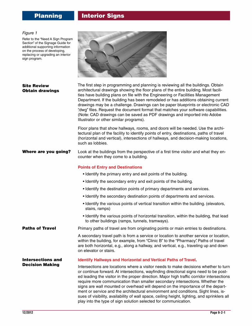
Figure 1Refer to the “Need A Sign Program Section” of the Signage Guide for additional supporting information on the process of developing, replacing or upgrading an interior sign program.
12/2012 Page 9-2-2
Interior Signs
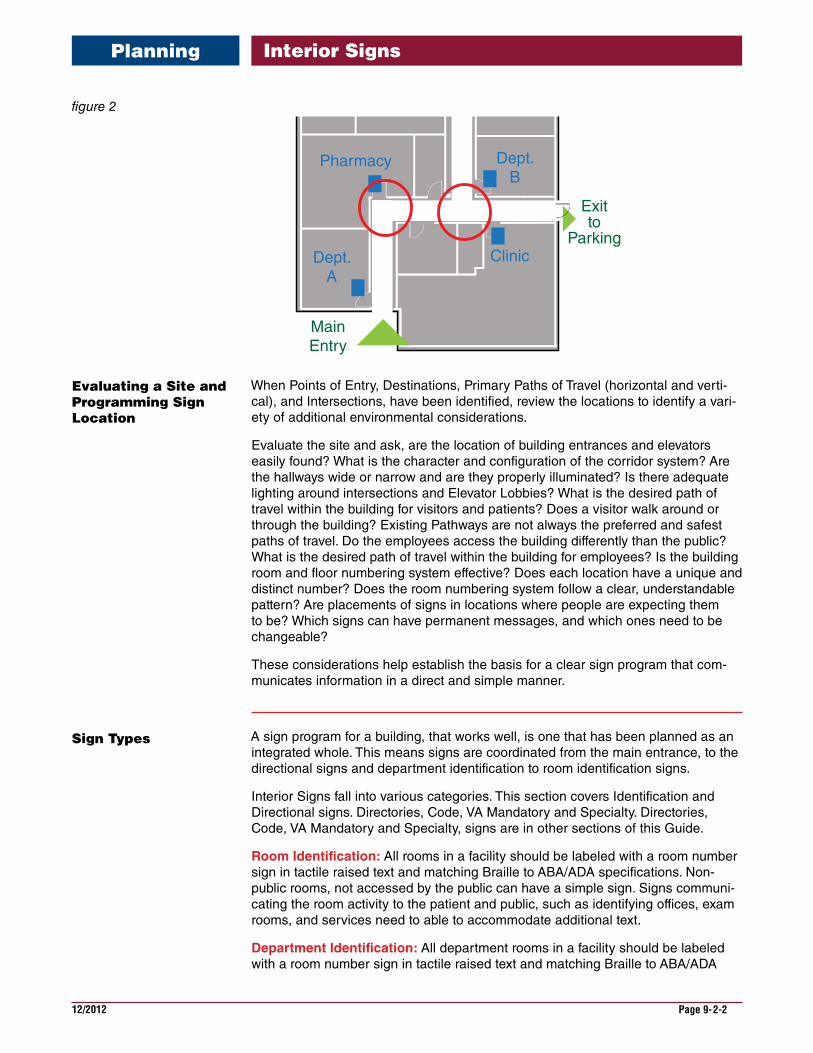
MainEntry
Pharmacy
Clinic
Exitto
Parking
Dept. B
Dept. A
When Points of Entry, Destinations, Primary Paths of Travel (horizontal and verti-cal), and Intersections, have been identified, review the locations to identify a vari-ety of additional environmental considerations.
Evaluate the site and ask, are the location of building entrances and elevators easily found? What is the character and configuration of the corridor system? Are the hallways wide or narrow and are they properly illuminated? Is there adequate lighting around intersections and Elevator Lobbies? What is the desired path of travel within the building for visitors and patients? Does a visitor walk around or through the building? Existing Pathways are not always the preferred and safest paths of travel. Do the employees access the building differently than the public? What is the desired path of travel within the building for employees? Is the building room and floor numbering system effective? Does each location have a unique and distinct number? Does the room numbering system follow a clear, understandable pattern? Are placements of signs in locations where people are expecting them to be? Which signs can have permanent messages, and which ones need to be changeable?
These considerations help establish the basis for a clear sign program that com-municates information in a direct and simple manner.
A sign program for a building, that works well, is one that has been planned as an integrated whole. This means signs are coordinated from the main entrance, to the directional signs and department identification to room identification signs.
Interior Signs fall into various categories. This section covers Identification and Directional signs. Directories, Code, VA Mandatory and Specialty. Directories, Code, VA Mandatory and Specialty, signs are in other sections of this Guide.
RoomIdentification: All rooms in a facility should be labeled with a room number sign in tactile raised text and matching Braille to ABA/ADA specifications. Non-public rooms, not accessed by the public can have a simple sign. Signs communi-cating the room activity to the patient and public, such as identifying offices, exam rooms, and services need to able to accommodate additional text.
DepartmentIdentification: All department rooms in a facility should be labeled with a room number sign in tactile raised text and matching Braille to ABA/ADA
EvaluatingaSiteandProgrammingSignLocation
SignTypes
Planning
figure 2
12/2012 Page 9-2-3
Interior Signs
specifications as well as be to able to accommodate additional text and description of services. Departments that occupy larger areas, such as with waiting rooms, re-quire additional identification designed to provide high visibility identification.
Directional: Wall, soffit, and ceiling mounted directional signs provide solutions for communicating wayfinding information in differing building conditions. Typically, ceiling or soffit mounted directional signs are used to display directional informa-tion for high traffic destinations like the Pharmacy or Clinics. Wall directional signs need to be obvious and present information in the order people will encounter the service or destination.
Directories: Directories in lobbies and at elevator landings serve to assist people in finding or confirming the location of services within a building or in other build-ings. Directories, because of their capability to handle a large number of service listings, can include all of the departments or services within the facility. See infor-mation on directories in another section of this Guide.
Once the building review is complete, you can begin to program the building.
Programming is the Where? What? and How? of signage. The Sign Location Plan establishes “where” a sign is located, The Sign Message Schedule establishes “what” text message on the sign is to say. The Sign Type Drawings show the type of sign and establish how the information is displayed. These three documents are the main components of signage programming. To create the Sign Location Plan place a mark and a location number on the plan document as a placeholder for a sign type and sign message associated with the particular location.
In the Message Schedule spreadsheet enter the Location Plan number, cor-responding Sign Type designation, and establish the text message of what that particular sign is to say. Sign type drawings are design documents that describe the sign size, text layouts and fabrication information. The VA has established sign types described in this section. This Programming process can be done for Code signs, Room/Department Identification and Wayfinding. These three categories of interior signs can be programmed concurrently or separately.
“Wayfinding” is the term, that in recent years has been used to describe the pro-cess of finding a destination in the built environment. Signs play an active role in the process by providing the primary form of communication in wayfinding.
In developing a wayfinding system for the interior of a medical center, or the inte-rior of a support building, follow some common guidelines. In the interior of a build-ing it involves the corridor system from all the building entrances to the locations where patients and visitors are seeking a service. Wayfinding is then the process of communicating to people along the pathway, with appropriate directories, direc-tional signs and service identification.
It is important to understand who will be using the wayfinding system. VA facilities will have a diverse clientele. A wayfinding system must take into account not only veterans of all ages and genders but family and friends that will need to locate patient rooms, departments, and services. Consideration of mobility, eye sight, the elderly walking stooped, or individuals using wheel chairs will effect sign position, location, and size of lettering.
Programming
Wayfinding
Planning
12/2012 Page 9-2-4
Interior Signs
It is new visitors who will depend the most on signs to navigate a facility. Be cau-tious, avoid information overload. Remember, once the viewer leaves the Directory, Map or Directional Sign, this new information will quickly fade. In the case of a “You Are Here” map, once they make the first turn, all their orientation will be lost.
When developing the information for directional signs, keep in mind that high traf-fic destinations should take top priority for being listed. Secondary services that are closest to the location of the sign then become the next group of items to list. Typically when including more that 6 to 8 destinations, people will stop reading a sign because of information overload.
The architectural environment will affect the wayfinding system. If the hall system is a maze, create a differentiation of floors and hallways. The colors of walls, memo-rable art work or unique interior details can help distinguish one floor from the next and one long corridor from another. Color and graphic treatments, changes in types of flooring and bright lighting at elevator lobbies and major intersections will aid in orienting the visitor.
Some older facilities that have been remodeled several times may have paths of travel that are blocked or inaccessible. The wayfind-ing path must catch and direct the visitor before they reach a blocked or limited path of travel. Signage cannot solve architectural problems.
Start planning from the main lobby or entry. In this main entry area an overview map of the facility and the main directory must be located. Select a primary wall, one easily visible from the entry door or elevator lobby for the main directory loca-tion. The directory should list primary services and departments alphabetically, NOT by floors. A new visitor usually knows what they are looking for so Directories and Directional signs need to tell the visitor where the department, room or service is located.
Additional Elevator Lobby Directories can be used at the elevator lobbies. These directories should list the services found on that floor and that are accessible from that elevator.
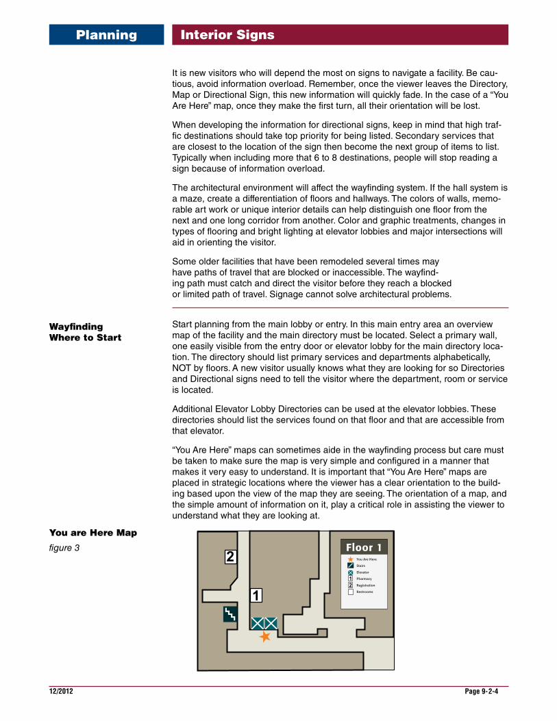
“You Are Here” maps can sometimes aide in the wayfinding process but care must be taken to make sure the map is very simple and configured in a manner that makes it very easy to understand. It is important that “You Are Here” maps are placed in strategic locations where the viewer has a clear orientation to the build-ing based upon the view of the map they are seeing. The orientation of a map, and the simple amount of information on it, play a critical role in assisting the viewer to understand what they are looking at.
Floor 1You Are Here
Stairs
Elevator
Pharmacy
Registration
Restrooms
12
WayfindingWheretoStart
YouareHereMap
figure 3
Planning
12/2012 Page 9-2-5
Interior Signs
Placement must also be at a location in the building where the viewer can make connection with major visuals objects like an atrium, or large “art” work, or a per-manent architectural feature of the building.
Directional signs should be used on walls and overhead along the path of travel. In the path of travel there will be decision points at each intersection of hallways or when encountering building exits or transitions. At these decision points, informa-tion must be communicated in a priority of need. The priority of need is defined as those departments or services that have the highest percentage of people seeking them. The destinations with high demand for information must be communicated with the highest priority on directional signs along the most direct path of travel.
Overhead signs generally provide emphasis to high priority directional or destina-tion information. Care must be taken with overhead signs to ensure that these signs can be seen from a distance. If the viewing distance is too short, those who walk stooped, are in walkers, or wheelchairs may have trouble viewing these signs. Also, the placement of overhead signs needs to take into account items that might obscure them, such as exit signs. Possible blocking of fire sprinklers also needs to be considered.
Secondary information or information that applies to a small percentage of indi-viduals needs to be evaluated in regard to its importance. Secondary information should be relegated to the bottom of the signs and not be included if the space on the sign is limited.
Typically a person only reads 4 to 8 messages on a directional sign. Any informa-tion greater than this is simply not read. Prioritization of communication of infor-mation would then in most cases result in secondary or minor information left off the sign because it is not useful.
People that are walking have the opportunity to read more messages than an automobile driver, therefore interior directional signs can contain more listings of information. But more than 8 listings on a sign results in a sign so large that it is no longer readable. The viewer simply cannot comprehend all the information pre-sented. Or they will not stand there long enough to read everything. When large amounts of information must be presented, break it down into smaller groups of information. Use 2 directional signs instead of 1. Place all the directional informa-tion for one direction on one sign, and then use another sign to covey the other directional information.
Planning
12/2012 Page 9-2-6
Interior Signs
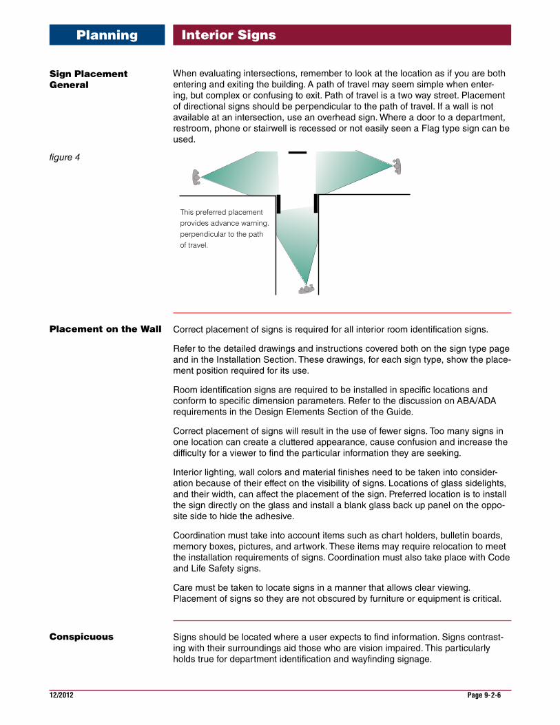
When evaluating intersections, remember to look at the location as if you are both entering and exiting the building. A path of travel may seem simple when enter-ing, but complex or confusing to exit. Path of travel is a two way street. Placement of directional signs should be perpendicular to the path of travel. If a wall is not available at an intersection, use an overhead sign. Where a door to a department, restroom, phone or stairwell is recessed or not easily seen a Flag type sign can be used.
This preferred placement provides advance warning.perpendicular to the path of travel.
Correct placement of signs is required for all interior room identification signs.
Refer to the detailed drawings and instructions covered both on the sign type page and in the Installation Section. These drawings, for each sign type, show the place-ment position required for its use.
Room identification signs are required to be installed in specific locations and conform to specific dimension parameters. Refer to the discussion on ABA/ADA requirements in the Design Elements Section of the Guide.
Correct placement of signs will result in the use of fewer signs. Too many signs in one location can create a cluttered appearance, cause confusion and increase the difficulty for a viewer to find the particular information they are seeking.
Interior lighting, wall colors and material finishes need to be taken into consider-ation because of their effect on the visibility of signs. Locations of glass sidelights, and their width, can affect the placement of the sign. Preferred location is to install the sign directly on the glass and install a blank glass back up panel on the oppo-site side to hide the adhesive.
Coordination must take into account items such as chart holders, bulletin boards, memory boxes, pictures, and artwork. These items may require relocation to meet the installation requirements of signs. Coordination must also take place with Code and Life Safety signs.
Care must be taken to locate signs in a manner that allows clear viewing. Placement of signs so they are not obscured by furniture or equipment is critical.
Signs should be located where a user expects to find information. Signs contrast-ing with their surroundings aid those who are vision impaired. This particularly holds true for department identification and wayfinding signage.
SignPlacementGeneral
figure 4
PlacementontheWall
Conspicuous
Planning
12/2012 Page 9-2-7
Interior SignsPlanning
As a general guide, is the sign conspicuous and does it stand out from visual clut-ter and its environment?
The text size needs to be an appropriate height for the distance from which the message is being viewed and what’s being communicated. Directional signs need to have text larger than room identification signs. Overhead signs and low light conditions require larger text size. ABA/ADA has certain text size requirements that must be met as well.
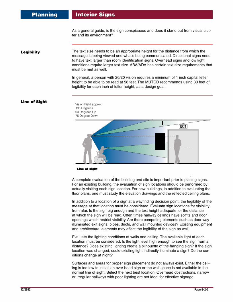
In general, a person with 20/20 vision requires a minimum of 1 inch capital letter height to be able to be read at 58 feet. The MUTCD recommends using 30 feet of legibility for each inch of letter height, as a design goal.
EXIT
Vision Field approx. 135 Degrees60 Degrees Up75 Degree Down
Line of sight
A complete evaluation of the building and site is important prior to placing signs. For an existing building, the evaluation of sign locations should be performed by actually visiting each sign location. For new buildings, in addition to evaluating the floor plans, one must study the elevation drawings and the reflected ceiling plans.
In addition to a location of a sign at a wayfinding decision point, the legibility of the message at that location must be considered. Evaluate sign locations for visibility from afar. Is the sign big enough and the text height adequate for the distance at which the sign will be read. Often times hallway ceilings have soffits and door openings which restrict visibility. Are there competing elements such as door way illuminated exit signs, pipes, ducts, and wall mounted devices? Existing equipment and architectural elements may effect the legibility of the sign as well.
Evaluate the lighting conditions at walls and ceiling. The available light at each location must be considered. Is the light level high enough to see the sign from a distance? Does existing lighting create a silhouette of the hanging sign? If the sign location was changed, could existing light indirectly illuminate a sign? Do the con-ditions change at night?
Surfaces and areas for proper sign placement do not always exist. Either the ceil-ing is too low to install an over head sign or the wall space is not available in the normal line of sight. Select the next best location. Overhead obstructions, narrow or irregular hallways with poor lighting are not ideal for effective signage.
Legibility
LineofSight
12/2012 Page 9-2-8
Interior Signs
The proper use of arrows on directional signs is important to ensure that the reader quickly understands correct directional information.
Grouping all the information together that is in one direction and using one arrow is pre-ferred. Using an arrow for each message makes the sign confusing and difficult to read.
Arrows should be placed to visually precede the message. This allows the reader to un-derstand direction first and information second. It also allows the arrows to be visually separated from text.
Arrows should always be larger in size than the text they are affiliated with. For example, wall directional signs have a 2-1/2” arrow and the text has a 1-3/8” capital letter size.
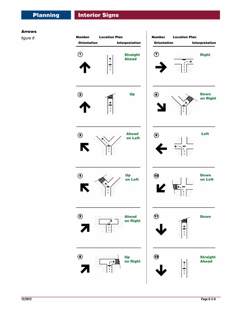
Orientation of arrows is important to effectively communicate direction. The following illustrations give examples of the many varied conditions that can be encountered when providing direction information.
Arrows
Planning
12/2012 Page 9-2-9
Interior Signs
Number
Orientation
Location Plan
Interpretation
Number
Orientation
Location Plan
Interpretation
Straight Ahead
Up
Ahead on Left
Up on Left
Ahead on Right
Upon Right
Right
Downon Right
Downon Left
Down
StraightAhead
Left
11
22
33
44
55
66
77
88
99
1010
1111
1212
Arrows
figure 6
Planning
12/2012 Page 9-2-10
Interior Signs
ColorandDesignContinuity
Planning
All the signs in a sign program do not have to be uniform in color.
A variety of color combinations will work well together. For example, the wayfinding portion of the sign program can be in a color that is different from the room identi-fication signs. Color is a strong design element helping to establish the mood and tone of an environment. Warm colors and cool colors as well as bright, saturated palettes can establish different styles and feelings for the interior environment. Also sign backer panels with contrasting color, finishes, patterns, or even photos can accent the desired color palette.
In the Design Elements section of the Guide a palette of colors has been prepared that work with most interior wall colors and finishes. If a color is selected that is not a part of the VA palette, it must meet the contrast requirements with the sign text that is called for by ABA/ADA.
12/2012 Page 9-2-11
Interior Signs
Receptionist
Pharmacy
Receptionist
Pharmacy
Receptionist
Pharmacy
RESTROOMRestroom
RESTROOMRestroom
RESTROOMRestroom
Code Color
Accent Pattern
Base Color
Accent Photo
Base & AccentColor
Accent Color
Code Color
Accent Color
Accent Pattern
Code Color
Sample Color palletsPattern with Cool colors
Sample Color Pallet:Photo header accent with warm colors
Sample Color Pallet:Pattern backer panel with accent and base neutral colors
Planning
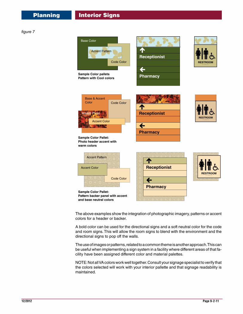
The above examples show the integration of photographic imagery, patterns or accent colors for a header or backer.
A bold color can be used for the directional signs and a soft neutral color for the code and room signs. This will allow the room signs to blend with the environment and the directional signs to pop off the walls.
The use of images or patterns, related to a common theme is another approach. This can be useful when implementing a sign system in a facility where different areas of that fa-cility have been assigned different color and material palettes.
NOTE: Not all VA colors work well together. Consult your signage specialist to verify that the colors selected will work with your interior pallette and that signage readability is maintained.
figure 7
12/2012 Page 9-2-12
Interior SignsPlanning
Interior sign sizes that are illustrated in this section have been determined to work in most situations. The size of text shown has also been determined to be the best compro-mise between readability and being able to fit text on the sign.
When planning a sign program, look for conditions that are within the building where signs will not fit. All buildings have these conditions. When encountered, have the spe-cific sign, at that location, modified in size to fit the specific condition requirements.
Text size on signs has also been predetermined to meet ABA/ADA requirements for the vision impaired. Overhead signs require large size lettering and lettering on directional signs should be larger than on room identification signs.
SizesofSignsandLettering
12/2012 Page 9-2-13
Interior SignsPlanning
figure 8
ContrastOutpatient Pharmacy
Blood Draw
*
Outpatient Pharmacy
Blood Draw
*
Outpatient Pharmacy & Prescription Refills
*
*
Pharmacy
*
OUTPATIENT SURGERYSTAFF ONLY
*
*
OutpatientSurgery
STAFF ONLY
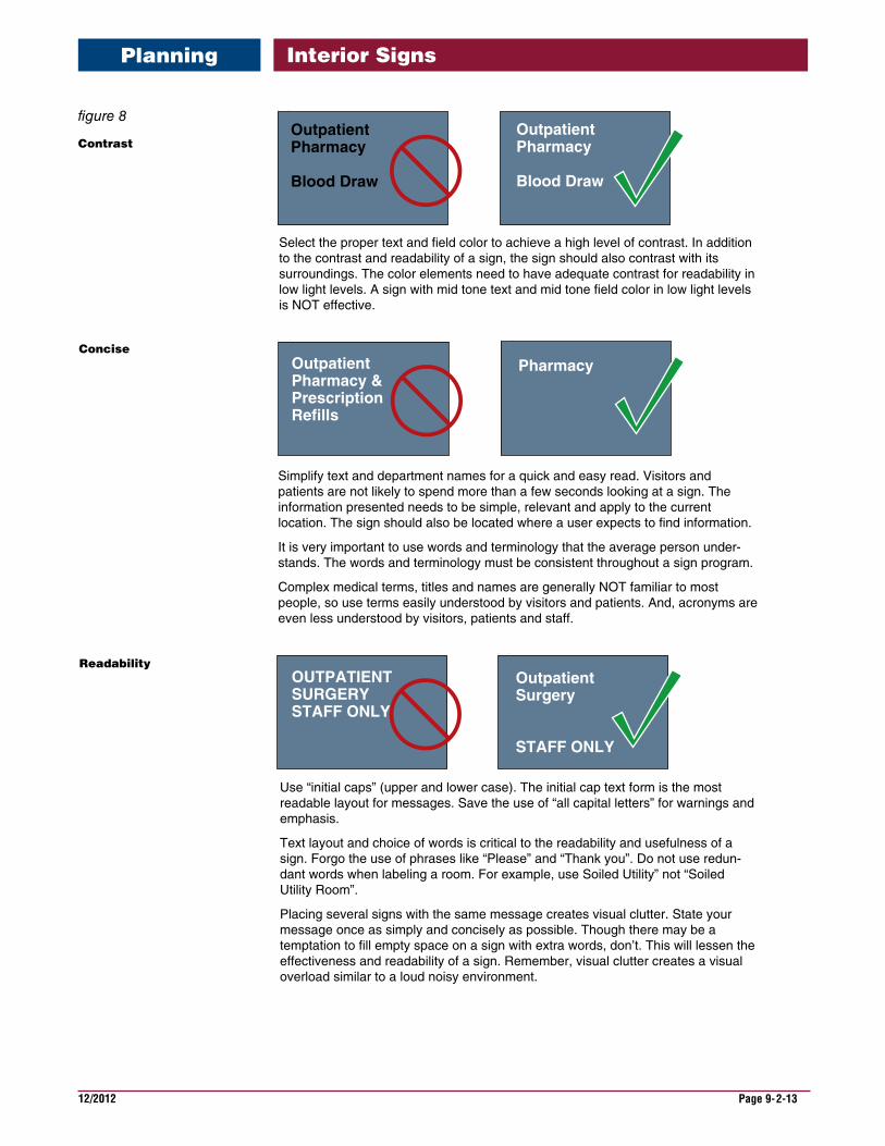
Select the proper text and field color to achieve a high level of contrast. In addition to the contrast and readability of a sign, the sign should also contrast with its surroundings. The color elements need to have adequate contrast for readability in low light levels. A sign with mid tone text and mid tone field color in low light levels is NOT effective.
Simplify text and department names for a quick and easy read. Visitors and patients are not likely to spend more than a few seconds looking at a sign. The information presented needs to be simple, relevant and apply to the current location. The sign should also be located where a user expects to find information.
It is very important to use words and terminology that the average person under-stands. The words and terminology must be consistent throughout a sign program.
Complex medical terms, titles and names are generally NOT familiar to most people, so use terms easily understood by visitors and patients. And, acronyms are even less understood by visitors, patients and staff.
Use “initial caps” (upper and lower case). The initial cap text form is the most readable layout for messages. Save the use of “all capital letters” for warnings and emphasis.
Text layout and choice of words is critical to the readability and usefulness of a sign. Forgo the use of phrases like “Please” and “Thank you”. Do not use redun-dant words when labeling a room. For example, use Soiled Utility” not “Soiled Utility Room”.
Placing several signs with the same message creates visual clutter. State your message once as simply and concisely as possible. Though there may be a temptation to fill empty space on a sign with extra words, don’t. This will lessen the effectiveness and readability of a sign. Remember, visual clutter creates a visual overload similar to a loud noisy environment.
Concise
Readability
12/2012 Page 9-2-14
Interior Signs
Before implementing a new interior sign program, perform a thorough evaluation of the demolition requirements of the current sign program and impact on the facility’s walls, doors and ceilings.
Determine what is required to patch, seal and repair the building surfaces exposed as a result of removal of old signs or letters. Repairs should match adjoining surfaces. Evaluate if tile or stone surfaces require repair or refurbishment. Are doors going to need to be refinished or painted?
Make sure the sign removal scope of work requires the contractor to disconnect and remove any live electrical connections. Make sure existing conductors and conduit are removed to the nearest junction box and are made safe.
Be sure to clearly identify any signs that are to remain. It is especially important to save signs and plaques that relate to special dedications, donors or displays that may be of historical importance. Cover or protect signs that are to remain or catalogue, remove, safely store and then reinstall as necessary.
ExistingSignProgramRemoval
Planning
12/2012 Page 9-3-1
Interior Signs
The following are some general “Dos and Don’ts” guidelines that one can use to develop a sign program.
The following is not intended to be a training section of the Guide, but to provide key information that will hopefully reduce the common errors made when developing an interior sign program.
• All tactile room number signs or other tactile room identification signs are required to meet ABA/ADA requirement for height and Braille text.
•Signs require maintenance. Periodic cleaning will extend the life of a sign program.
•If overhead signs are used, make sure they have a minimum 84 inches of clearance from the bottom of the sign to the floor.
•Signs identifying electrical closets, mechanical rooms and telecommunication rooms should consist of the room number only, which should follow the master building room numbering system. No descriptive name or title should be used nor should they have a unique number system.
•Overhead signs must not visually block EXIT signs and shall not block fire sprinkler spray patterns.
• Keep sign messages brief. Unnecessary information confuses the viewer. Typically, all signs, with the exception of directional signs, should convey no more than one name, title, concept, or thought.
•Use words which are familiar and comfortable to the viewer, and use the same words consistently throughout the sign program.
•On directional and informational signs, provide only information necessary to make a decision at that particular location.
•Whenever possible, messages should be presented using positive information.
•On directional signs, do not anticipate decisions that can be made later. Unnecessary or premature information will confuse the reader.
•Messages placed on signs should be concise, preferably with no more than seven to ten words.
•Use upper and lower case text whenever possible. Upper and lower case text is easi-er to read and is understood faster than text in all capital letters.
•Line spacing between two different messages should be greater than line spacing between lines of the same multi-line message group.
•Generally sign text should be a minimum of 1/2” capital letter height. ABA/ADA tac-tile text is a minimum 5/8”.
•Text should not go right up to the edge of the sign.
•If a line of text needs to be reduced in order to fit on a sign, use only commonly understood abbreviations or reduce the size of the type for the entire message. DO NOT condense the type face.
•The most important message should appear as the first line of text.
GeneralGuidelines
MessageContent
MessageLayout
HelpfulHints
12/2012 Page 9-3-2
Interior Signs
•On wall mounted directional signs, the most important directional information should be at the top of the sign.
•On a ceiling mounted directional sign, the most important directional information should be at the bottom of the sign.
•Signs should, if at all possible, always be perpendicular to the intended viewer.
•Position signs with a clear line of sight from the viewing point to the sign face.
•Always evaluate the lighting at a sign’s location. Lighting conditions can have a sig-nificant effect on visibility, possibly making a particular location unsuitable.
•Evaluate the sign color selections for effective contrast and readability in the actual building condition or location where the sign will be installed.
•All signs should be placed in a location that will be clearly visible at all times.
•Signs may be installed on glass when there is no available wall surface. A blank glass back up is necessary on the opposite side of the glass, exactly behind the sign being installed.
PlacementofSigns
HelpfulHints
12/2012 Page 9-3-3
Interior Signs
Letting people know where they are and where they need to go is just as important in historical buildings.
In a historic building, if original signs exist, they should be used as a starting point for developing a new sign program that respects the original design look, but meets the current requirements for interior signs.
Sensitivity to colors, materials, finishes, building detail, and the original architects intent for the look of the building should be incorporated into the look and design of a new sign program. The sign product for a new sign program should be of the type that allows for updating and text changes to be conducted with out complete sign removal and reinstallation.
Care must be taken to not harm building materials when removing old signs and installing new ones. Placement of wayfinding signs in a historic building must take into account circulation constraints that are sometimes a part of older corridor sys-tems, as well as vertical movement within a building. Glass doors, special doors, high wainscot, special paneling, carvings, and trim detail may require compromise on sign placement, but locating signs should follow the interior sign installation guidelines as closely as possible.
Keep signs to a minimum and consolidate them whenever possible. Signs in lob-bies should be kept to a minimum and consist of only those necessary for people to find their way in the building. Announcement banners, notices and other “pro-motional” type items should be discouraged in lobbies and throughout the corridor system.
Additional assistance with sign programs for historical building is available from the Office of Construction & Facilities Management.
HistoricVABuildings
Historical

This page is intentionally left blank.
12/2012 Page 9-4-1
Interior Signs
This section of the VA Signage Design Guide covers interior signs that would be neces-sary to sign an individual buildings, off site clinics or a complete medical center campus.
This Overview Section gives general illustrations of the sign type groups. Page section 9.5 identifies all interior room signs, identification, directional, wayfinding and infor-mational signs. The sign type drawings are on two pages with the front page showing the general description and the back page illustrating the sign dimensions and graphic layouts.
InteriorSignDesignationsEach sign in the program guide has been given a specific sign type number des-ignation. This designation provides a description that can be referenced when pro-gramming a building and ordering signs. The following explains how the sign type designations are derived.
IN-03.01AIN Designates an interior sign.
03 Two digit numbers identify a particular sign type family.
.01The two digit number following the period identifies a specific sign within the sign family.
AThe letter designates a specific sign configuration, version or layout for graphics
Overview

12/2012 Page 9-4-2
Interior Signs
252442A244
Nurse Supervisor
SoiledUtility
252442A244
252442A244
IN-03.01Room
IN-04.02Of�ce (Small)
IN-04.01Of�ce (Large)
OutpatientConferenceRoom
252442A244
IN-04.03Room (Large Insert)
OutpatientConferenceRoom
252442A244
IN-04.04Room (Small Insert)
SoiledUtility
IN-05.07Patient Room Sign(With Patient ConditionsPull outs )
IN-05.08Double Patient Room Sign(With Patient ConditionsPull outs)
IN-05.06Patient Room Sign
ANPO
B 5624-1
52822528625286
ANPO
252862286
BED
A Door
BED
B Window
2528625286
25286
Overview
IN-03.01 Room Number Identification
IN-04.01 Primary Room Identification (Large)
IN-04.02Secondary Room Identification (Small)
IN-04.03 Primary Room Identification (Large with paper Insert and lens)
IN-04.04 Secondary Room Identification (Small with paper Insert and lens)
IN-05.06 Patient Room Identification
IN-05.07 Patient Room Identification with Patient Condition pull outs
IN-05.08Double Patient Room Identification
12/2012 Page 9-4-3
Interior Signs
OutpatientConferenceRoom
In UseIn Use
IN-07.01, and .03 /IN-07.05, and .07Slider
Exam A
IN-07.02 / IN-07.06Slider (Small)
IN-08.01
No SmokingAuthorized
Personnel Only
IN-08.02-4
IN-09.03IN-09.01 IN-09.02
B 5624-1
52822528625286
MEN
B 5624-1
52822528625286
WOMEN
B 5624-1
52822528625286
RESTROOM
2528625286
2528625286
ANPO
A2
BED
A2
BED
IN-06.05 IN-06.06
Overview
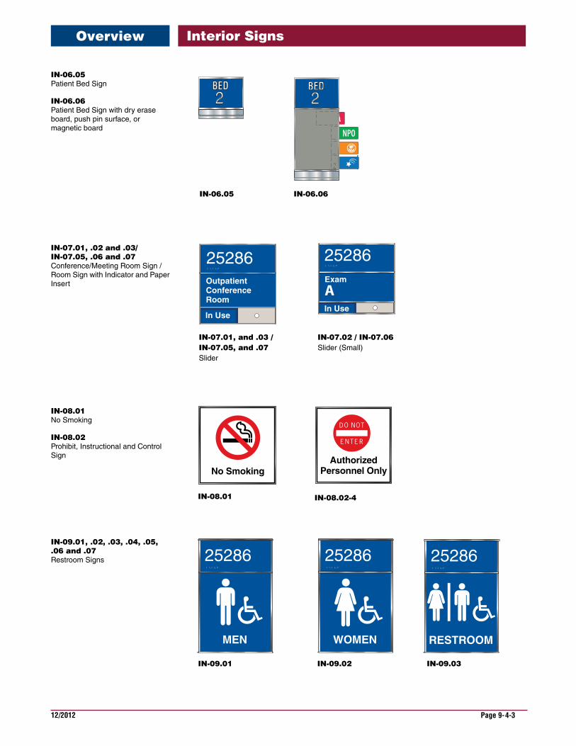
IN-06.05 Patient Bed Sign
IN-06.06 Patient Bed Sign with dry erase board, push pin surface, or magnetic board
IN-07.01,.02and.03/IN-07.05,.06and.07 Conference/Meeting Room Sign / Room Sign with Indicator and Paper Insert
IN-08.01 No Smoking
IN-08.02 Prohibit, Instructional and Control Sign
IN-09.01,.02,.03,.04,.05,.06and.07 Restroom Signs
12/2012 Page 9-4-4
Interior Signs
For PatientInformationPlease use telephones located at the information desk in the main lobby.
IN-11.01, .02, .03.04, .05, .06
IN-09.08, .09 IN-10.01, .02, .03, .04, .05, .06Pocket Insert
Telephone
Clinic B Check In
IN-12.01, .02, .03, .04Desk Top
Restrooms
IN-13.01Flag
ReceptionistPTSD
SurgeryPharmacyCanteen
IN-14.01, .02, .03, .04, .05Wall Directional(strips)
ReceptionistPTSD
SurgeryPharmacyCanteen
IN-14.06, .07, .08, .09, .10Wall Directional(Digital print insert)
Overview
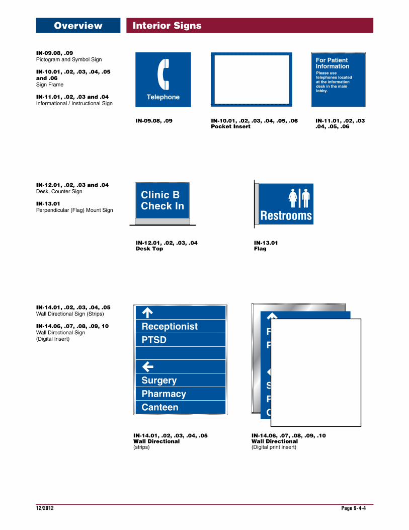
IN-09.08,.09 Pictogram and Symbol Sign
IN-10.01,.02,.03,.04,.05and.06 Sign Frame
IN-11.01,.02,.03and.04 Informational / Instructional Sign
IN-12.01,.02,.03and.04 Desk, Counter Sign
IN-13.01 Perpendicular (Flag) Mount Sign
IN-14.01,.02,.03,.04,.05 Wall Directional Sign (Strips)
IN-14.06,.07,.08,.09,10 Wall Directional Sign (Digital Insert)
12/2012 Page 9-4-5
Interior Signs
F L O O RF O U R4
PharmacySurgery
You Are HereSurgery
Pharmacy
4F L O O RF O U R
Reception
SurgeryPatient Rooms4235 Thru 4357
4
IN-14.11, .12, .13, .14Elevator Directional(strips)
F L O O RF O U R
Reception
SurgeryPatient Rooms4235 Thru 4357
IN-14.15, .16, .17, .18Elevator DIrectional(Digital print insert)
IN-14.20, .21Elevator DIrectional(strips with map)
F L O O RF O U R4
IN-14.25, .26Elevator DIrectional(digital print insert)
You Are HereSurgery
Pharmacy
Pharmacy
Surgery
Overview
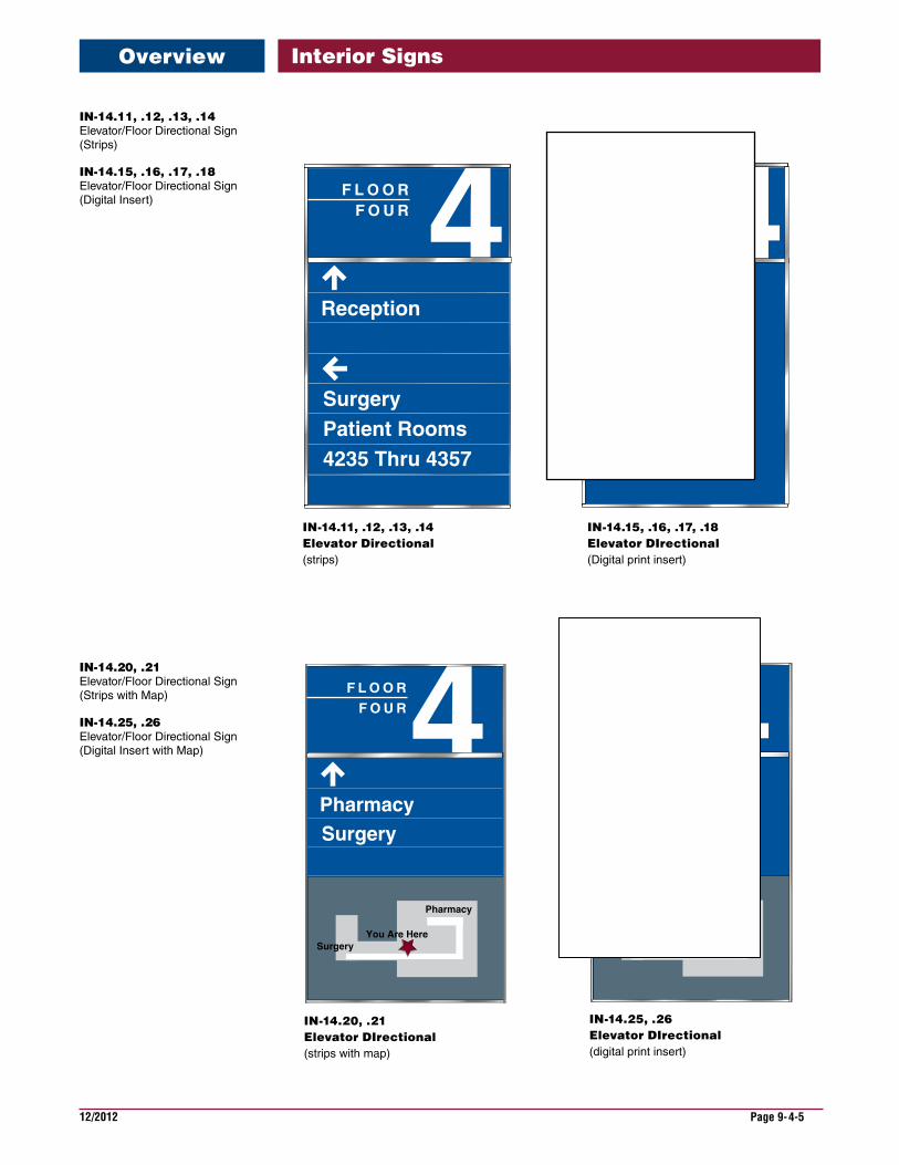
IN-14.11,.12,.13,.14 Elevator/Floor Directional Sign (Strips)
IN-14.15,.16,.17,.18 Elevator/Floor Directional Sign (Digital Insert)
IN-14.20,.21 Elevator/Floor Directional Sign (Strips with Map)
IN-14.25,.26 Elevator/Floor Directional Sign (Digital Insert with Map)
12/2012 Page 9-4-6
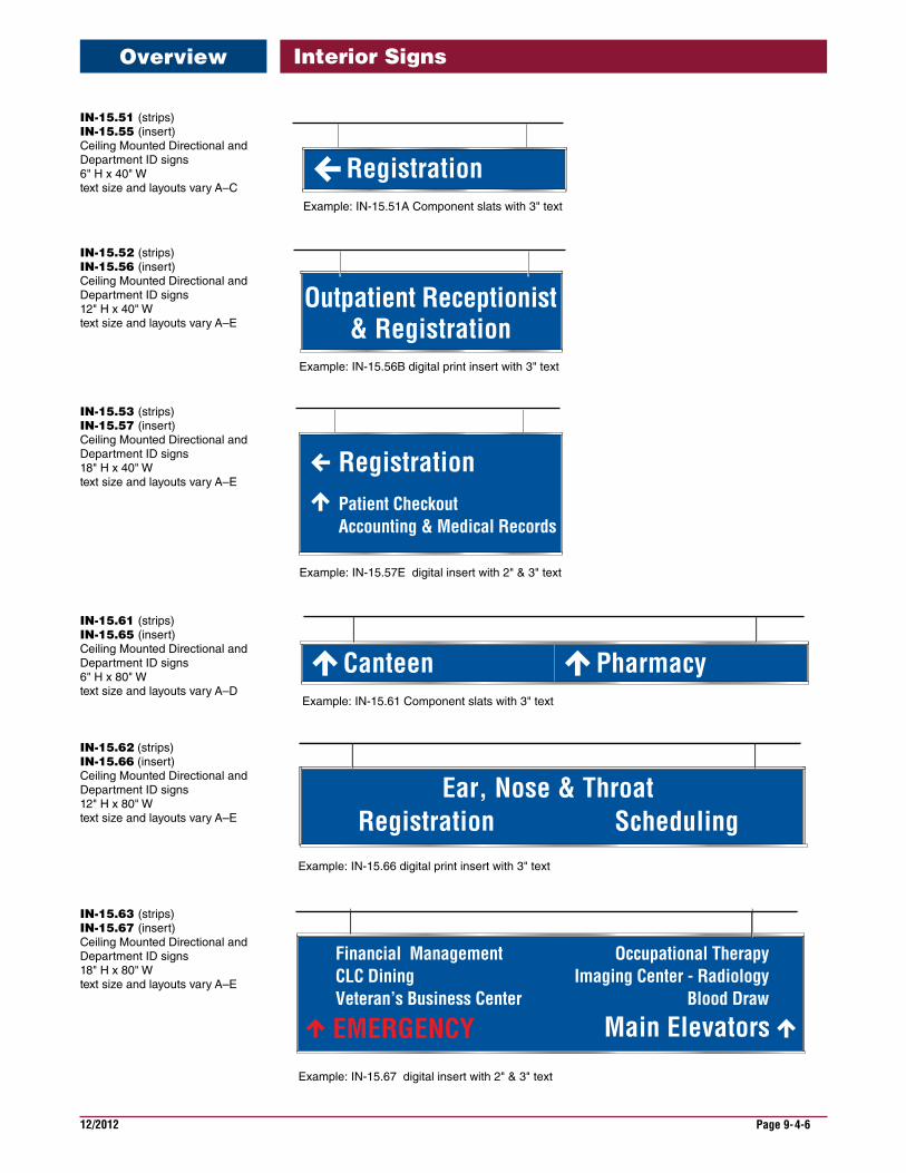
Interior SignsOverview
Registration
Outpatient Receptionist& Registration
SchedulingRegistrationEar, Nose & Throat
Patient CheckoutAccounting & Medical Records
Canteen Pharmacy
Occupational TherapyImaging Center - Radiology
Blood Draw
Main Elevators
Financial ManagementCLC DiningVeteran’s Business Center
EMERGENCY
Registration
Example: IN-15.51A Component slats with 3" text
Example: IN-15.56B digital print insert with 3" text
Example: IN-15.57E digital insert with 2" & 3" text
Example: IN-15.61 Component slats with 3" text
Example: IN-15.66 digital print insert with 3" text
Example: IN-15.67 digital insert with 2" & 3" text
IN-15.51(strips)IN-15.55(insert) Ceiling Mounted Directional and Department ID signs 6" H x 40" W text size and layouts vary A–C
IN-15.52(strips) IN-15.56(insert) Ceiling Mounted Directional and Department ID signs 12" H x 40" W text size and layouts vary A–E
IN-15.53(strips) IN-15.57(insert) Ceiling Mounted Directional and Department ID signs 18" H x 40" W text size and layouts vary A–E
IN-15.61(strips) IN-15.65(insert) Ceiling Mounted Directional and Department ID signs 6" H x 80" W text size and layouts vary A–D
IN-15.62 (strips) IN-15.66 (insert) Ceiling Mounted Directional and Department ID signs 12" H x 80" W text size and layouts vary A–E
IN-15.63(strips) IN-15.67(insert) Ceiling Mounted Directional and Department ID signs 18" H x 80" W text size and layouts vary A–E

12/2012 Page 9-4-7
Interior Signs
CanteenSpinal Rehab
Component/Strips Family
Flat InsertFamily
Curve InsertFamily
Spinal Rehabilitation
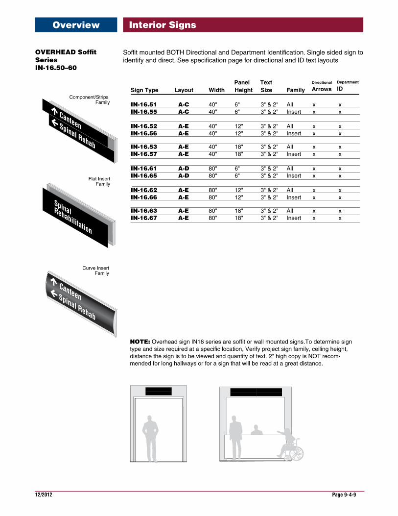
Sign Type Layout Width Height Size Family
IN-15.51 A -C 40" 6" 3" & 2" All x xIN-15.55 A-C 40" 6" 3" & 2" Insert x x
IN-15.52 A -E 40" 12" 3" & 2" All x x IN-15.56 A -E 40" 12" 3" & 2" Insert x x
IN-15.53 A -E 40" 18" 3" & 2" All x x IN-15.57 A -E 40" 18" 3" & 2" Insert x x
IN-15.61 A -C 80" 6" 3" & 2" All x xIN-15.65 A-C 80" 6" 3" & 2" Insert x x
IN-15.62 A -E 80" 12" 3" & 2" All x x IN-15.66 A -E 80" 12" 3" & 2" Insert x x
IN-15.63 A -E 80" 18" 3" & 2" All x x IN-15.67 A -E 80" 18" 3" & 2" Insert x x
NOTE: Overhead sign IN15 series are double sided hanging signs.To determine sign type and size required at a specific location, Verify project sign family, ceiling height, distance the sign is to be viewed and quantity of text. 2" high copy is NOT recom-mended for long hallways or for a sign that will be read at a great distance.
Directional
Arrows Panel Text Department
ID
Overview
OVERHEADHangingSeriesIN-15.50-60
N15 series can be used for BOTH Directional and Department Identification. See specification page for directional and ID text layouts
12/2012 Page 9-4-8
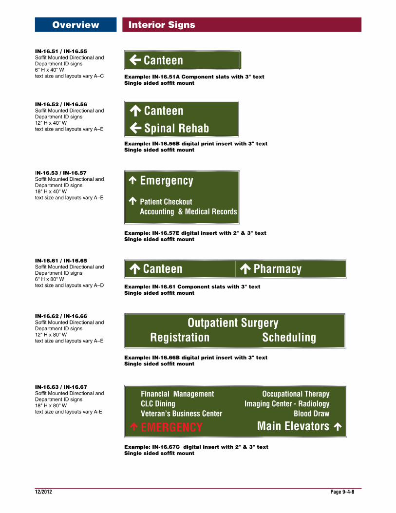
Interior Signs
SchedulingRegistrationOutpatient Surgery
Spinal RehabCanteen
Canteen Pharmacy
Occupational TherapyImaging Center - Radiology
Blood Draw
Main Elevators
Financial ManagementCLC DiningVeteran’s Business Center
EMERGENCY
Example: IN-16.51A Component slats with 3" textSingle sided sof�t mount
Example: IN-16.56B digital print insert with 3" textSingle sided sof�t mount
Example: IN-16.57E digital insert with 2" & 3" text Single sided sof�t mount
Example: IN-16.61 Component slats with 3" textSingle sided sof�t mount
Example: IN-16.66B digital print insert with 3" textSingle sided sof�t mount
Example: IN-16.67C digital insert with 2" & 3" textSingle sided sof�t mount
Canteen
Emergency
Patient CheckoutAccounting & Medical Records
Overview
IN-16.51/IN-16.55Soffit Mounted Directional and Department ID signs 6" H x 40" W text size and layouts vary A–C
IN-16.52/IN-16.56 Soffit Mounted Directional and Department ID signs 12" H x 40" W text size and layouts vary A–E
IN-16.53/IN-16.57 Soffit Mounted Directional and Department ID signs 18" H x 40" W text size and layouts vary A–E
IN-16.61/IN-16.65 Soffit Mounted Directional and Department ID signs 6" H x 80" W text size and layouts vary A–D
IN-16.62/IN-16.66 Soffit Mounted Directional and Department ID signs 12" H x 80" W text size and layouts vary A–E
IN-16.63/IN-16.67 Soffit Mounted Directional and Department ID signs 18" H x 80" W text size and layouts vary A-E
12/2012 Page 9-4-9
Interior Signs
CanteenSpinal Rehab
Component/Strips Family
Flat InsertFamily
Curve InsertFamily
Spinal Rehabilitation
Sign Type Layout Width Height Size Family
IN-16.51 A -C 40" 6" 3" & 2" All x xIN-16.55 A-C 40" 6" 3" & 2" Insert x x
IN-16.52 A -E 40" 12" 3" & 2" All x x IN-16.56 A -E 40" 12" 3" & 2" Insert x x
IN-16.53 A -E 40" 18" 3" & 2" All x x IN-16.57 A -E 40" 18" 3" & 2" Insert x x
IN-16.61 A -D 80" 6" 3" & 2" All x xIN-16.65 A-D 80" 6" 3" & 2" Insert x x
IN-16.62 A -E 80" 12" 3" & 2" All x x IN-16.66 A -E 80" 12" 3" & 2" Insert x x
IN-16.63 A -E 80" 18" 3" & 2" All x x IN-16.67 A -E 80" 18" 3" & 2" Insert x x
NOTE: Overhead sign IN16 series are soffit or wall mounted signs.To determine sign type and size required at a specific location, Verify project sign family, ceiling height, distance the sign is to be viewed and quantity of text. 2" high copy is NOT recom-mended for long hallways or for a sign that will be read at a great distance.
Directional
Arrows Panel Text Department
ID
Overview
OVERHEADSoffitSeriesIN-16.50–60
Soffit mounted BOTH Directional and Department Identification. Single sided sign to identify and direct. See specification page for directional and ID text layouts

This page is intentionally left blank.
12/2012 Page 9-5-1
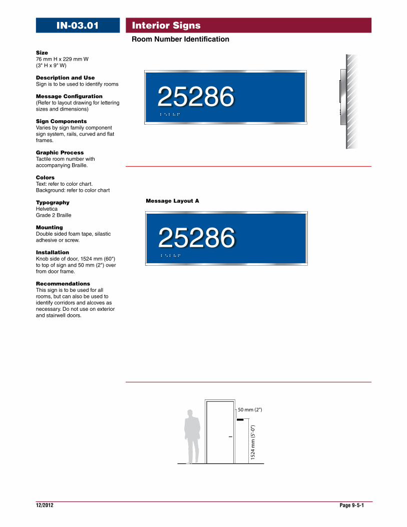
Interior SignsRoomNumberIdentification
IN-03.01
Size 76 mm H x 229 mm W (3" H x 9" W)
DescriptionandUse Sign is to be used to identify rooms
MessageConfiguration (Refer to layout drawing for lettering sizes and dimensions)
SignComponents Varies by sign family component sign system, rails, curved and flat frames.
GraphicProcess Tactile room number with accompanying Braille.
Colors Text: refer to color chart. Background: refer to color chart
Typography Helvetica Grade 2 Braille
Mounting Double sided foam tape, silastic adhesive or screw.
Installation Knob side of door, 1524 mm (60") to top of sign and 50 mm (2") over from door frame.
Recommendations This sign is to be used for all rooms, but can also be used to identify corridors and alcoves as necessary. Do not use on exterior and stairwell doors.
Message Layout A
50 mm (2")
1524
mm
(5'-0
")
2528625286
2528625286
2528625286
2528625286

12/2012 Page 9-5-2
Interior SignsRoomNumberIdentification
IN-03.01
Raised Letters
Braille
End View
A-2578
1 1/4”height
1/8” MinLetter Spacing
Copy Helvetica Medium raised tactile text
BrailleGrade 2Domed
3/8” Minclear space
3/8” Min. clear space
3/8” Min. clear space
Approx 1/4”
3/8” Minclear space 3/8” Min
clear space
Baseline Spacing
Front View
1/2”
Braille
3/8"
3/4"
229 mm (9”)
3"
1/2"
1 1/4"
3/8"1/4"
25286
50 mm (2")
1524
mm
(5'-0
")
12/2012 Page 9-5-3
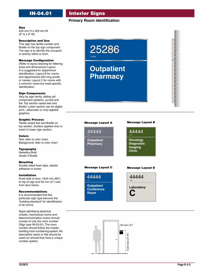
Interior SignsPrimaryRoomIdentification
IN-04.01
25286
Message Layout A
Message Layout D
Message Layout B
50 mm (2")
1524
mm
(5'-0
")
OutpatientPharmacy
44444 44444
OncologyDiagnostic ImagingClinic
44444
Laboratory
C
2528625286
OutpatientConferenceRoom
44444
44444
OutpatientPharmacy
44444 4444444444
44444444444444444444
Message Layout C
Size 229 mm H x 229 mm W (9" H x 9" W)
DescriptionandUse This sign has tactile number and Braille on the top sign component. The sign is to identify the occupant or activity within a room.
MessageConfiguration (Refer to layout drawing for lettering sizes and dimensions) Layout A is suggested for department identification. Layout B for rooms and departments with long words or names. Layout C for rooms with a common name but need specific identification.
SignComponents Vary by sign family, sliding rail component systems, curved and flat. Top section raised text and Braille. Lower section can be digital print, ,silkscreen or vinyl applied graphics.
GraphicProcess Tactile raised text and Braille on top section. Surface applied vinyl or insert in lower sign section.
Colors Text: refer to color chart. Background: refer to color chart
Typography Helvetica Bold Grade 2 Braille
Mounting Double sided foam tape, silastic adhesive or screw.
Installation Knob side of door, 1524 mm (60") to top of sign and 50 mm (2") over from door frame.
Recommendations It is recommended that this particular sign type become the "building standard" for identification of all rooms.
Signs identifying electrical closets, mechanical rooms and telecommunication rooms should consist of only the room number (Sign type IN-03.01). The room number should follow the master building room numbering system. No descriptive name or title should be used nor should they have a unique number system.

12/2012 Page 9-5-4
Interior SignsPrimaryRoomIdentification
IN-04.01
Message Layout C
Message Layout A & B
Message Layout D
50 mm (2")
1524
mm
(5'-0
")
12/2012 Page 9-5-5
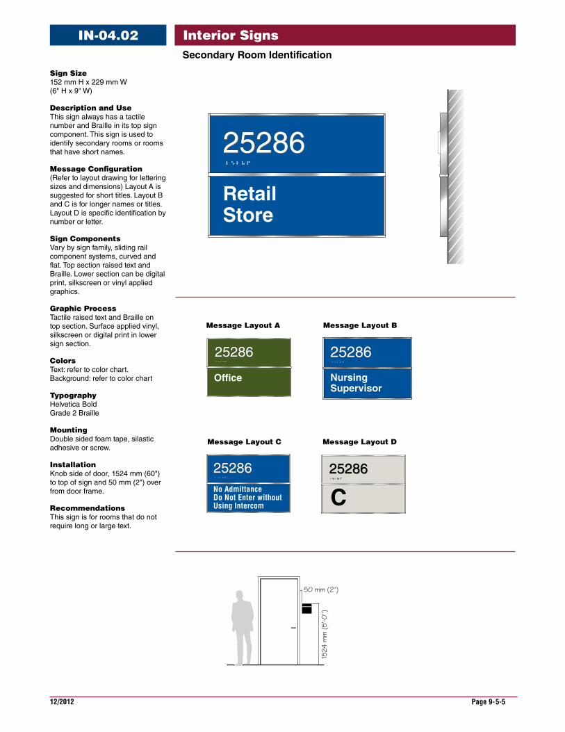
Interior SignsSecondaryRoomIdentification
IN-04.02
Message Layout A
Message Layout C
Message Layout B
50 mm (2")
1524
mm
(5'-0
")
RetailStore
2528625286
Office
25286
No AdmittanceDo Not Enter withoutUsing Intercom
2528625286 25286
C
25286
25286
2528625286
2528625286
Nursing Supervisor
2528625286
25286
Message Layout D
SignSize 152 mm H x 229 mm W (6" H x 9" W)
DescriptionandUse This sign always has a tactile number and Braille in its top sign component. This sign is used to identify secondary rooms or rooms that have short names.
MessageConfiguration (Refer to layout drawing for lettering sizes and dimensions) Layout A is suggested for short titles. Layout B and C is for longer names or titles. Layout D is specific identification by number or letter.
SignComponents Vary by sign family, sliding rail component systems, curved and flat. Top section raised text and Braille. Lower section can be digital print, silkscreen or vinyl applied graphics.
GraphicProcess Tactile raised text and Braille on top section. Surface applied vinyl, silkscreen or digital print in lower sign section.
Colors Text: refer to color chart.Background: refer to color chart
Typography Helvetica Bold Grade 2 Braille
Mounting Double sided foam tape, silastic adhesive or screw.
Installation Knob side of door, 1524 mm (60") to top of sign and 50 mm (2") over from door frame.
Recommendations This sign is for rooms that do not require long or large text.
12/2012 Page 9-5-6
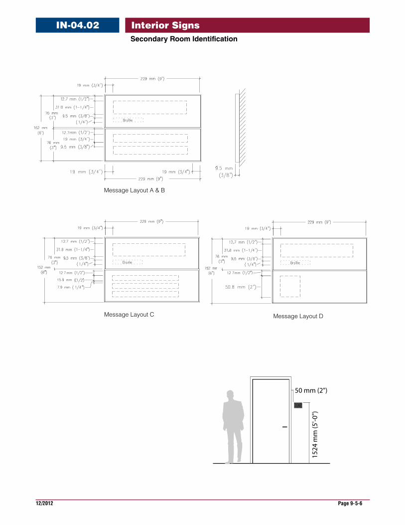
Interior SignsIN-04.02SecondaryRoomIdentification
Message Layout C
Message Layout A & B
Message Layout D
50 mm (2")
1524
mm
(5'-0
")
12/2012 Page 9-5-7
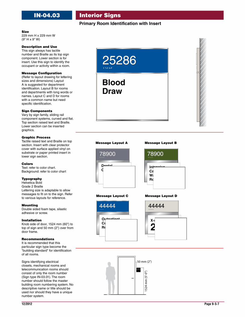
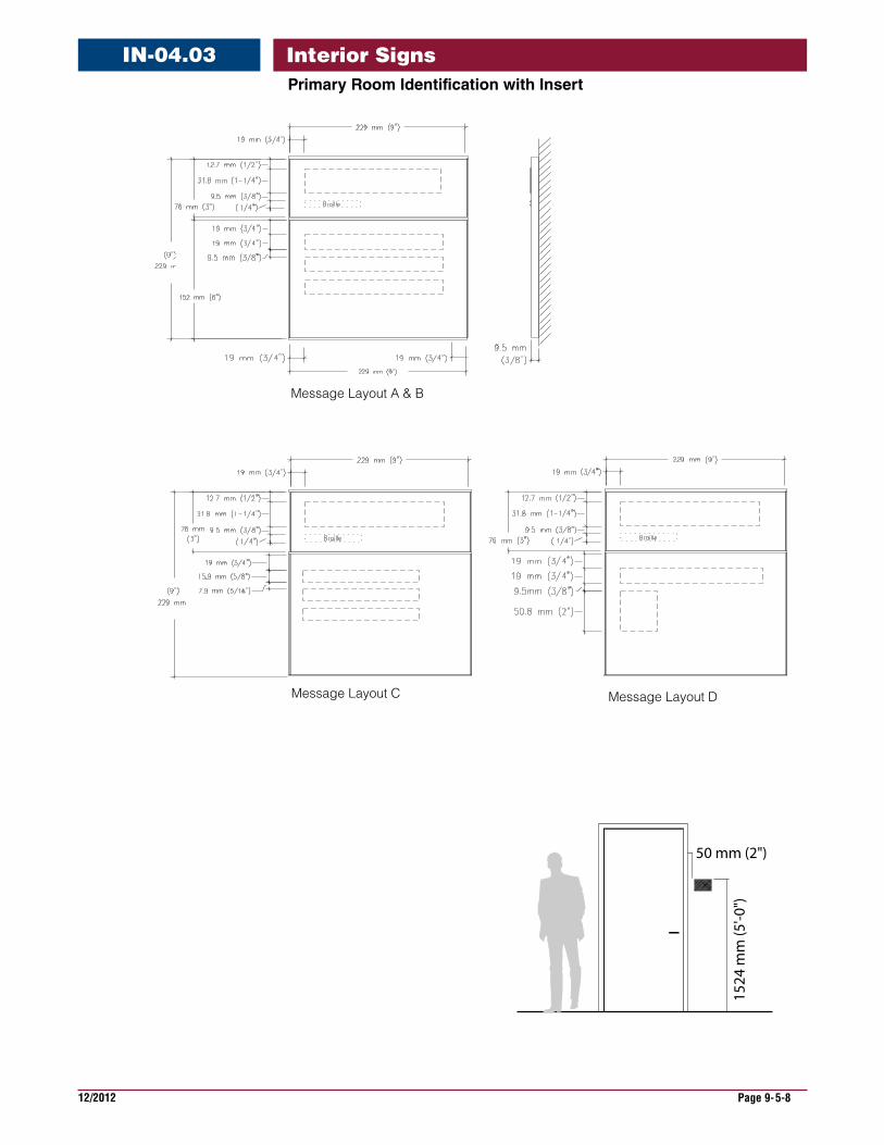
Interior SignsPrimaryRoomIdentificationwithInsert
IN-04.03
Size 229 mm H x 229 mm W (9" H x 9" W)
DescriptionandUse This sign always has tactile number and Braille as its top sign component. Lower section is for insert. Use this sign to identify the occupant or activity within a room.
MessageConfiguration (Refer to layout drawing for lettering sizes and dimensions) Layout A is suggested for department identification. Layout B for rooms and departments with long words or names. Layout C and D for rooms with a common name but need specific identification.
SignComponents Vary by sign family, sliding rail component systems, curved and flat. Top section raised text and Braille. Lower section can be inserted graphics.
GraphicProcess Tactile raised text and Braille on top section. Insert with clear protector cover with surface applied vinyl on substrate or paper printed insert in lower sign section.
Colors Text: refer to color chart. Background: refer to color chart
Typography Helvetica Bold Grade 2 Braille Lettering size is adaptable to allow messages to fit on to the sign. Refer to various layouts for reference.
Mounting Double sided foam tape, silastic adhesive or screw.
Installation Knob side of door, 1524 mm (60") to top of sign and 50 mm (2") over from door frame.
Recommendations It is recommended that this particular sign type become the "building standard" for identification of all rooms.
Signs identifying electrical closets, mechanical rooms and telecommunication rooms should consist of only the room number (Sign type IN-03.01). The room number should follow the master building room numbering system. No descriptive name or title should be used nor should they have a unique number system.
25286
Message Layout A
Message Layout D
Message Layout B
50 mm (2")
1524
mm
(5'-0
")
Blood Draw
44444 44444
44444
X-ray
2
2528625286
OutpatientConferenceRoom
OutpatientConferenceRoom
44444
7890078900 7890078900
44444444444444444444
Message Layout C
IntensiveCareWaitingRoom
DentalClinic
12/2012 Page 9-5-8
Interior SignsPrimaryRoomIdentificationwithInsert
IN-04.03
Message Layout C
Message Layout A & B
Message Layout D
50 mm (2")
1524
mm
(5'-0
")
12/2012 Page 9-5-9
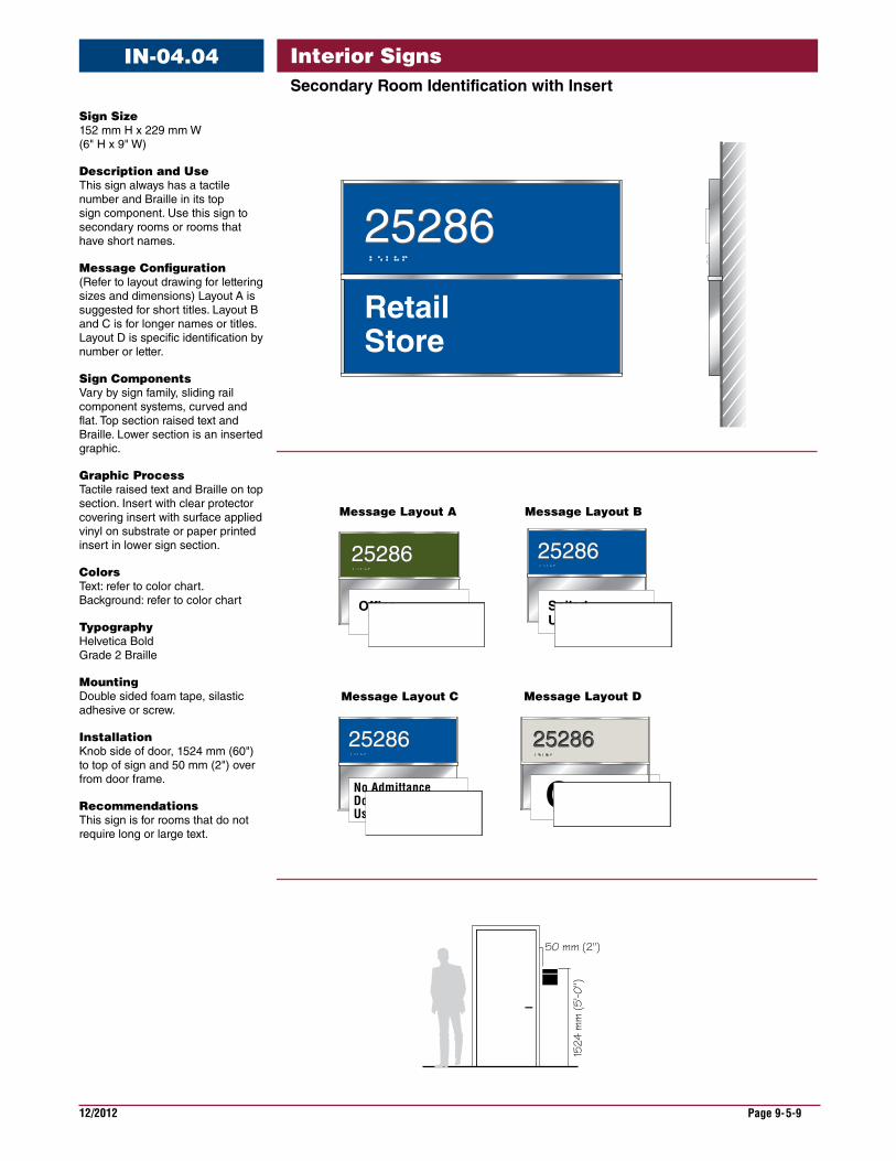
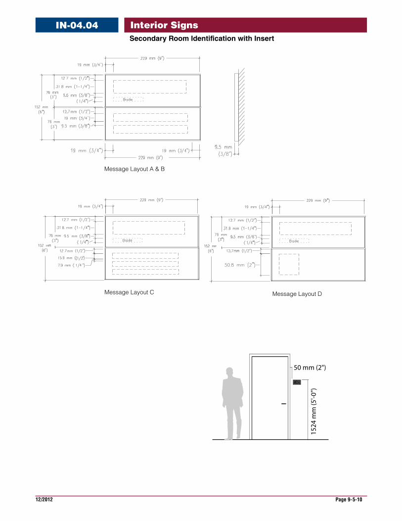
Interior SignsSecondaryRoomIdentificationwithInsert
IN-04.04
SignSize 152 mm H x 229 mm W (6" H x 9" W)
DescriptionandUse This sign always has a tactile number and Braille in its top sign component. Use this sign to secondary rooms or rooms that have short names.
MessageConfiguration (Refer to layout drawing for lettering sizes and dimensions) Layout A is suggested for short titles. Layout B and C is for longer names or titles. Layout D is specific identification by number or letter.
SignComponents Vary by sign family, sliding rail component systems, curved and flat. Top section raised text and Braille. Lower section is an inserted graphic.
GraphicProcess Tactile raised text and Braille on top section. Insert with clear protector covering insert with surface applied vinyl on substrate or paper printed insert in lower sign section.
Colors Text: refer to color chart. Background: refer to color chart
Typography Helvetica Bold Grade 2 Braille
Mounting Double sided foam tape, silastic adhesive or screw.
Installation Knob side of door, 1524 mm (60") to top of sign and 50 mm (2") over from door frame.
Recommendations This sign is for rooms that do not require long or large text.
25286
Message Layout A
Message Layout C
Message Layout B
50 mm (2")
1524
mm
(5'-0
")
RetailStore
2528625286
Office
25286
25286
SoiledUtilities
25286
25286
2528625286 2528625286
2528625286
2528625286
No AdmittanceDo Not Enter withoutUsing Intercom
C
Message Layout D
12/2012 Page 9-5-10
Interior SignsSecondaryRoomIdentificationwithInsert
IN-04.04
Message Layout C
Message Layout A & B
Message Layout D
50 mm (2")
1524
mm
(5'-0
")
12/2012 Page 9-5-11
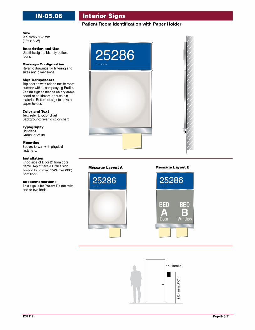
Interior SignsPatientRoomIdentificationwithPaperHolder
IN-05.06
Size 229 mm x 152 mm (9"H x 6"W)
DescriptionandUse Use this sign to identify patient room.
MessageConfiguration Refer to drawings for lettering and sizes and dimensions.
SignComponents Top section with raised tactile room number with accompanying Braille. Bottom sign section to be dry erase board or corkboard or push pin material. Bottom of sign to have a paper holder.
ColorandText Text: refer to color chart Background: refer to color chart
Typography Helvetica Grade 2 Braille
Mounting Secure to wall with physical fasteners.
Installation Knob side of Door 2" from door frame. Top of tactile Braille sign section to be max. 1524 mm (60") from floor.
Recommendations This sign is for Patient Rooms with one or two beds.
50 mm (2")
1524
mm
(5'-0
")
B 5624-1
C5282
2528625286
25286
Message Layout A
2528625286
25286
Message Layout B
2528625286
25286
12/2012 Page 9-5-12
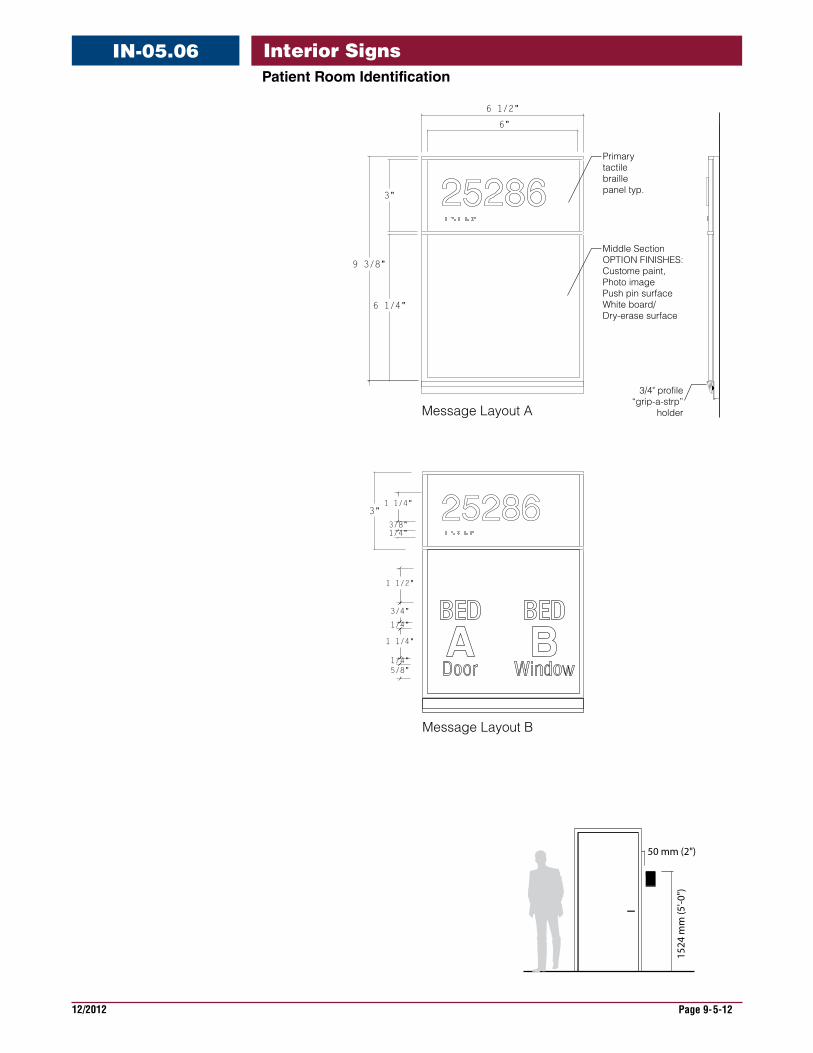
Interior SignsPatientRoomIdentification
IN-05.06
6"
6 1/2"
3"
6 1/4"
9 3/8"
Primary tactilebraille panel typ.
Message Layout B
3"
Message Layout A
1 1/4"
3/8"1/4"
3/4" profile“grip-a-strp”
holder
1 1/2"
3/4"
1/4"
1 1/4"
1/4"5/8"
Middle SectionOPTION FINISHES:Custome paint, Photo image Push pin surface White board/Dry-erase surface
50 mm (2")
1524
mm
(5'-0
")
B 5624-1
C5282
12/2012 Page 9-5-13
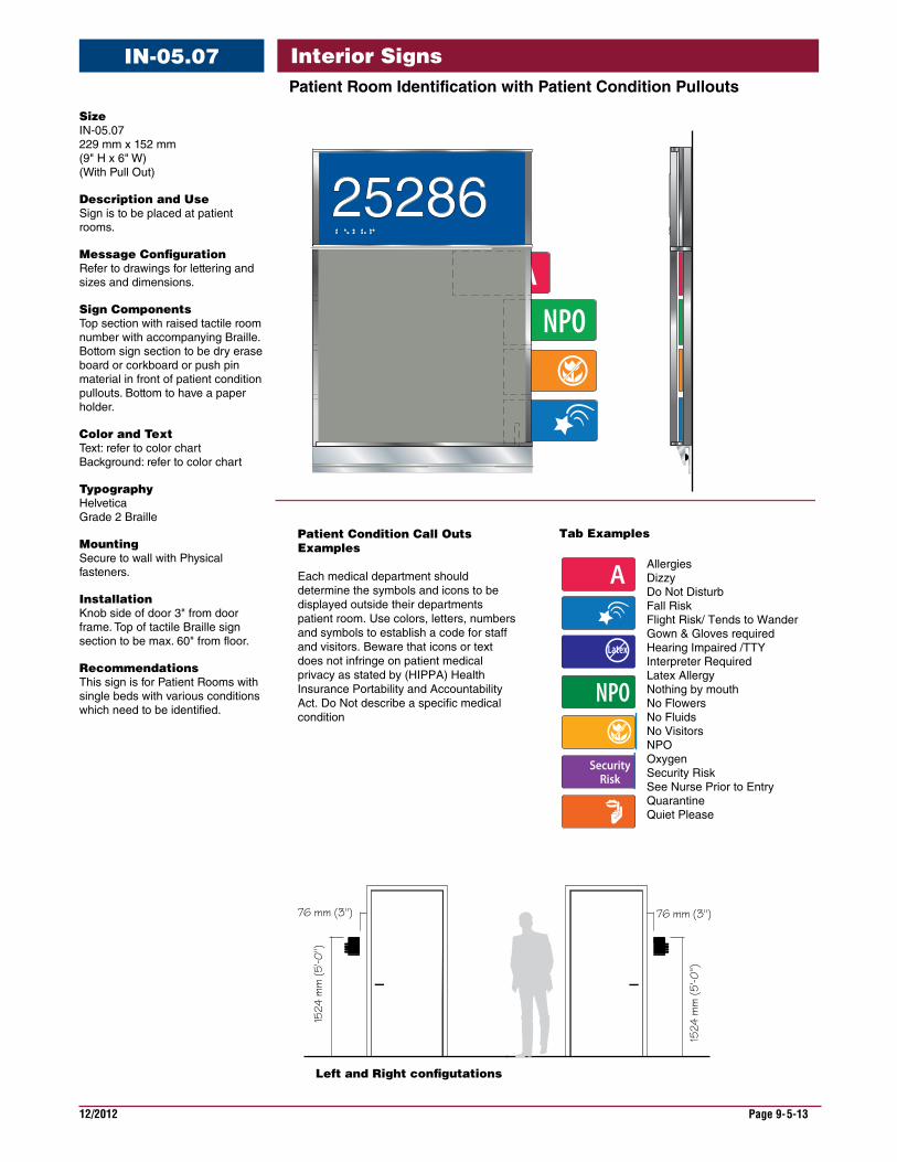
Interior SignsPatientRoomIdentificationwithPatientConditionPullouts
IN-05.07
Size IN-05.07 229 mm x 152 mm (9" H x 6" W) (With Pull Out)
DescriptionandUse Sign is to be placed at patient rooms.
MessageConfiguration Refer to drawings for lettering and sizes and dimensions.
SignComponents Top section with raised tactile room number with accompanying Braille. Bottom sign section to be dry erase board or corkboard or push pin material in front of patient condition pullouts. Bottom to have a paper holder.
ColorandText Text: refer to color chart Background: refer to color chart
Typography Helvetica Grade 2 Braille
Mounting Secure to wall with Physical fasteners.
Installation Knob side of door 3" from door frame. Top of tactile Braille sign section to be max. 60" from floor.
Recommendations This sign is for Patient Rooms with single beds with various conditions which need to be identified.
ANPO
76 mm (3")
1524
mm
(5'-0
")
B 5624-1
5282
AN
B 5624-1
C5282
2528625286
A
NPO
Patient Condition Call OutsExamples
Each medical department should determine the symbols and icons to be displayed outside their departments patient room. Use colors, letters, numbers and symbols to establish a code for staff and visitors. Beware that icons or text does not infringe on patient medical privacy as stated by (HIPPA) Health Insurance Portability and Accountability Act. Do Not describe a specific medical condition
SecurityRisk
Latex
AllergiesDizzyDo Not DisturbFall RiskFlight Risk/ Tends to WanderGown & Gloves required Hearing Impaired /TTYInterpreter Required Latex AllergyNothing by mouth No FlowersNo FluidsNo VisitorsNPOOxygenSecurity Risk See Nurse Prior to Entry Quarantine Quiet Please
76 mm (3")
1524
mm
(5'-0
")
AN
B 5624-1
C5282
Left and Right con�gutations
25286
Tab Examples
12/2012 Page 9-5-14
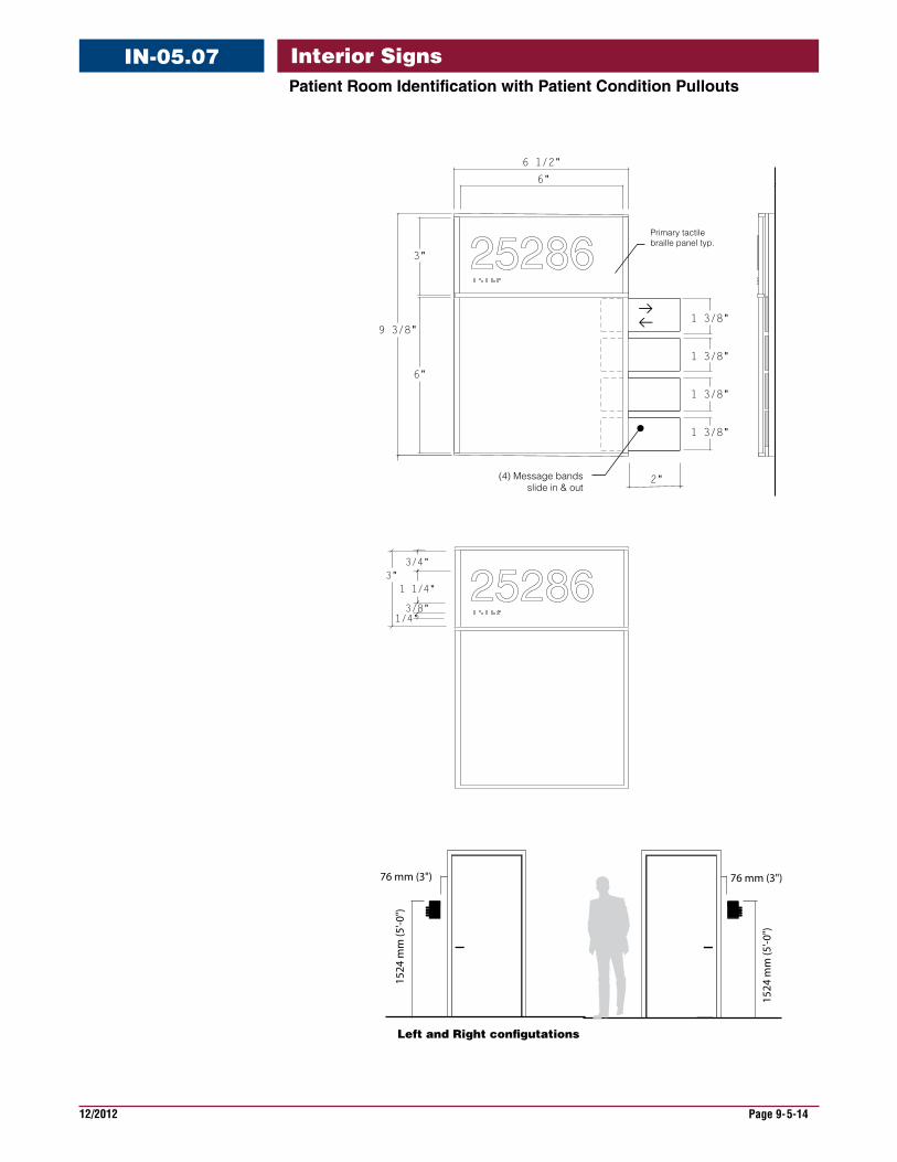
Interior SignsPatientRoomIdentificationwithPatientConditionPullouts
IN-05.07
25286
2"
6"
6 1/2"
3"
6"
9 3/8"
1 3/8"
1 3/8"
1 3/8"
1 3/8"
(4) Message bandsslide in & out
Primary tactilebraille panel typ.
25286
2528625286
3/4"
1 1/4"
3/8"1/4"
3"
76 mm (3")
1524
mm
(5'-0
")
AN
B 5624-1
C5282
76 mm (3")
1524
mm
(5'-0
")
AN
B 5624-1
C5282
Left and Right con�gutations
12/2012 Page 9-5-15
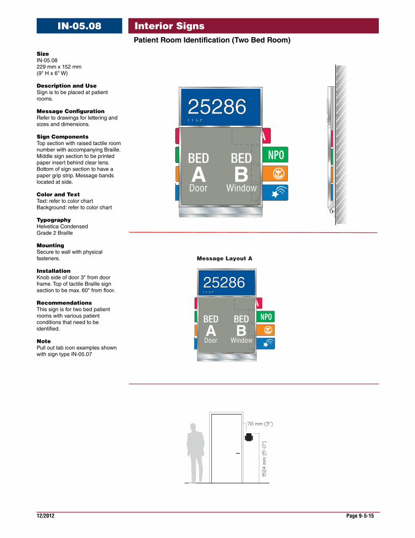
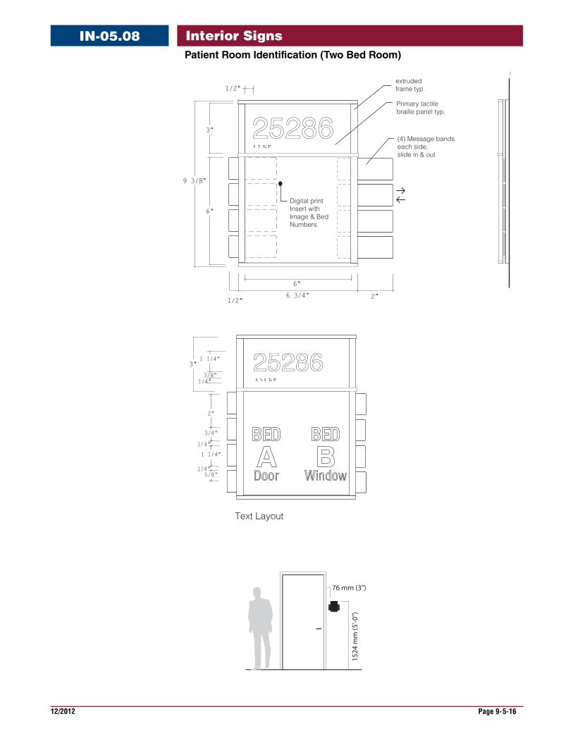
Interior SignsPatientRoomIdentification(TwoBedRoom)
IN-05.08
Size IN-05.08 229 mm x 152 mm (9" H x 6" W)
DescriptionandUse Sign is to be placed at patient rooms.
MessageConfiguration Refer to drawings for lettering and sizes and dimensions.
SignComponents Top section with raised tactile room number with accompanying Braille. Middle sign section to be printed paper insert behind clear lens. Bottom of sign section to have a paper grip strip. Message bands located at side.
ColorandText Text: refer to color chart Background: refer to color chart
Typography Helvetica Condensed Grade 2 Braille
Mounting Secure to wall with physical fasteners.
Installation Knob side of door 3" from door frame. Top of tactile Braille sign section to be max. 60" from floor.
Recommendations This sign is for two bed patient rooms with various patient conditions that need to be identified.
Note Pull out tab icon examples shown with sign type IN-05.07
76 mm (3")
1524
mm
(5'-0
")
AN
B 5624-1
C5282
AN
B 5624-1
C5282
ANPO
2286
25286
Message Layout A
ANPO
2286
25286
12/2012 Page 9-5-16
Interior SignsPatientRoomIdentification(TwoBedRoom)
IN-05.08
Text Layout
6"
2"1/2"
6 3/4"
3"
6"
9 3/8"
Digital print Insert with Image & Bed Numbers.
2286
(4) Message bandseach side,slide in & out
Primary tactilebraille panel typ.
extruded frame typ.
25286
1/2"
3"1 1/4"
3/8"1/4"
2"
3/4"
1/4"
1 1/4"
1/4"5/8"
76 mm (3")
1524
mm
(5'-0
")
AN
B 5624-1
C5282
AN
B 5624-1
C5282
12/2012 Page 9-5-17
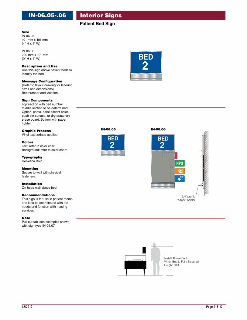
Interior SignsPatientBedSign
IN-06.05-.06
ANPO
3/4" profile“paper” holder
A2
BED
A2
BED
IN-06.05 IN-06.06
Install Above Bed When Bed is Fully ElevatedHeight TBD
A2
BED
Size IN-06.05 101 mm x 101 mm (4" H x 4" W)
IN-06.06 229 mm x 101 mm (9" H x 4" W)
DescriptionandUse Use this sign above patient beds to identify the bed.
MessageConfiguration (Refer to layout drawing for lettering sizes and dimensions) Bed number and location
SignComponents Top section with bed number middle section to be determined. Option: photo, paint accent color, push pin surface, or dry erase dry erase board. Bottom with paper holder.
GraphicProcess Vinyl text surface applied.
Colors Text: refer to color chart. Background: refer to color chart
Typography Helvetica Bold
Mounting Secure to wall with physical fasteners.
Installation On head wall above bed.
Recommendations This sign is for use in patient rooms and is to be coordinated with the needs and function with nursing services.
Note Pull out tab icon examples shown with sign type IN-05.07
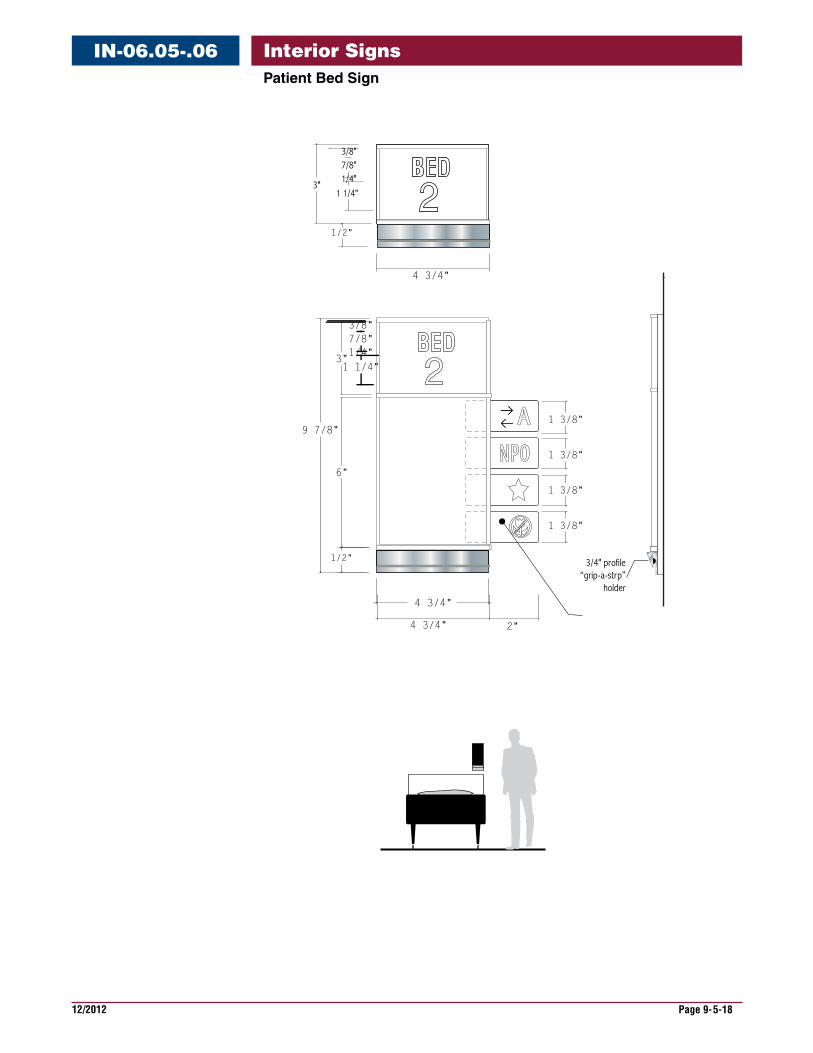
12/2012 Page 9-5-18
Interior SignsPatientBedSign
IN-06.05-.06
3/4" profile“grip-a-strp”
holder
3"
3/8"7/8"1/4"
1 1/4" 2BED
2"4 3/4"
3"
6"
ANPO
1 3/8"
1 3/8"
1 3/8"
1 3/8"
3/8"7/8"1/4"
1 1/4" 2BED
4 3/4"
9 7/8"
1/2"
1/2"
4 3/4"
12/2012 Page 9-5-19
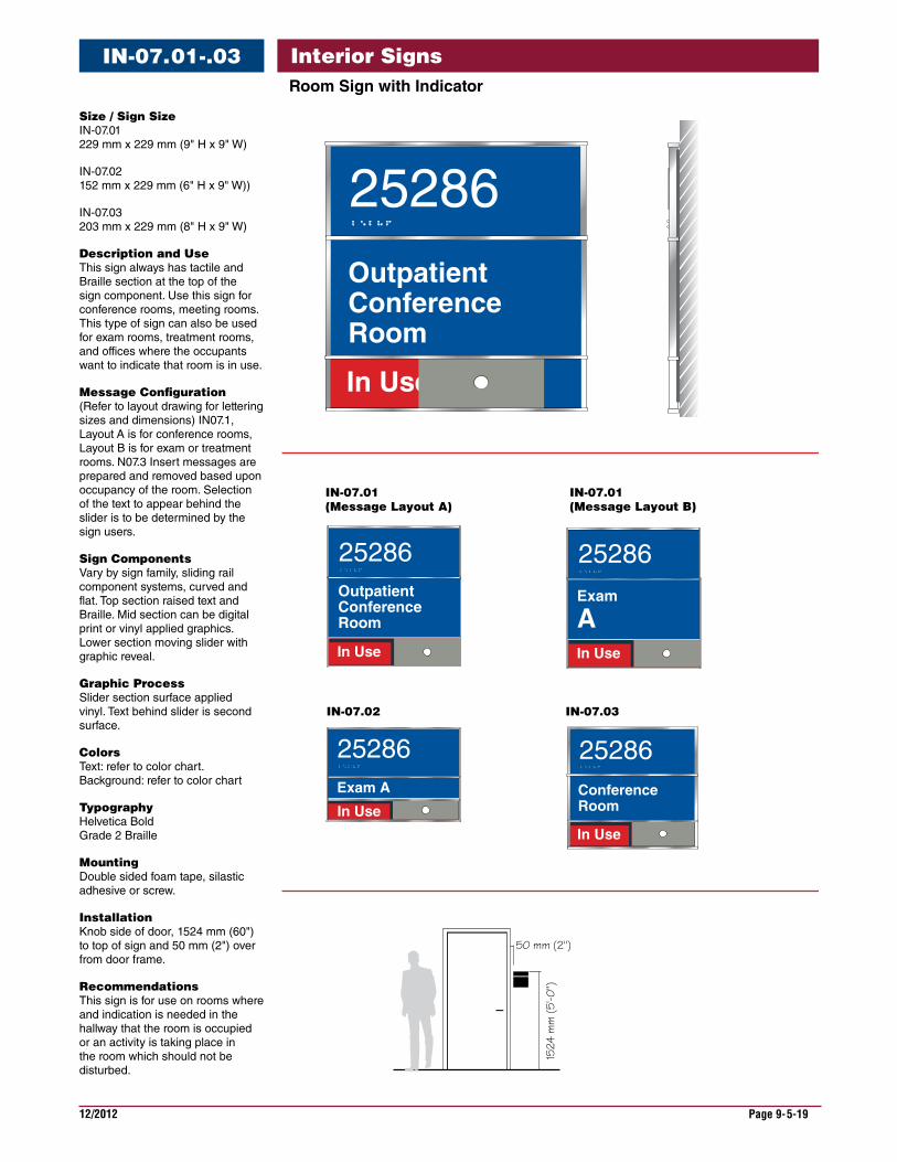
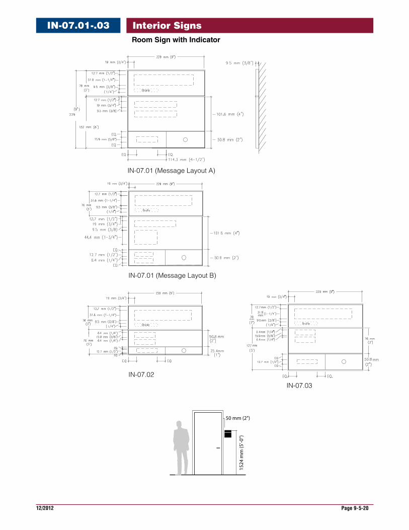
Interior SignsRoomSignwithIndicator
IN-07.01-.03
IN-07.01 (Message Layout A)
IN-07.01 (Message Layout B)
IN-07.02 IN-07.03
50 mm (2")
1524
mm
(5'-0
")
OutpatientConferenceRoom
In Use
In Use
Exam A
2528625286
2528625286
OutpatientConferenceRoom
In Use
2528625286
In Use
2528625286
Exam
A
ConferenceRoom
In Use
2528625286
Size/SignSize IN-07.01 229 mm x 229 mm (9" H x 9" W)
IN-07.02 152 mm x 229 mm (6" H x 9" W))
IN-07.03 203 mm x 229 mm (8" H x 9" W)
DescriptionandUse This sign always has tactile and Braille section at the top of the sign component. Use this sign for conference rooms, meeting rooms. This type of sign can also be used for exam rooms, treatment rooms, and offices where the occupants want to indicate that room is in use.
MessageConfiguration (Refer to layout drawing for lettering sizes and dimensions) IN07.1, Layout A is for conference rooms, Layout B is for exam or treatment rooms. N07.3 Insert messages are prepared and removed based upon occupancy of the room. Selection of the text to appear behind the slider is to be determined by the sign users.
SignComponents Vary by sign family, sliding rail component systems, curved and flat. Top section raised text and Braille. Mid section can be digital print or vinyl applied graphics. Lower section moving slider with graphic reveal.
GraphicProcess Slider section surface applied vinyl. Text behind slider is second surface.
Colors Text: refer to color chart. Background: refer to color chart
Typography Helvetica Bold Grade 2 Braille
Mounting Double sided foam tape, silastic adhesive or screw.
Installation Knob side of door, 1524 mm (60") to top of sign and 50 mm (2") over from door frame.
Recommendations This sign is for use on rooms where and indication is needed in the hallway that the room is occupied or an activity is taking place in the room which should not be disturbed.
12/2012 Page 9-5-20
Interior SignsIN-07.01-.03RoomSignwithIndicator
50 mm (2")
1524
mm
(5'-0
")
IN-07.01 (Message Layout A)
IN-07.01 (Message Layout B)
IN-07.02
IN-07.03
12/2012 Page 9-5-21
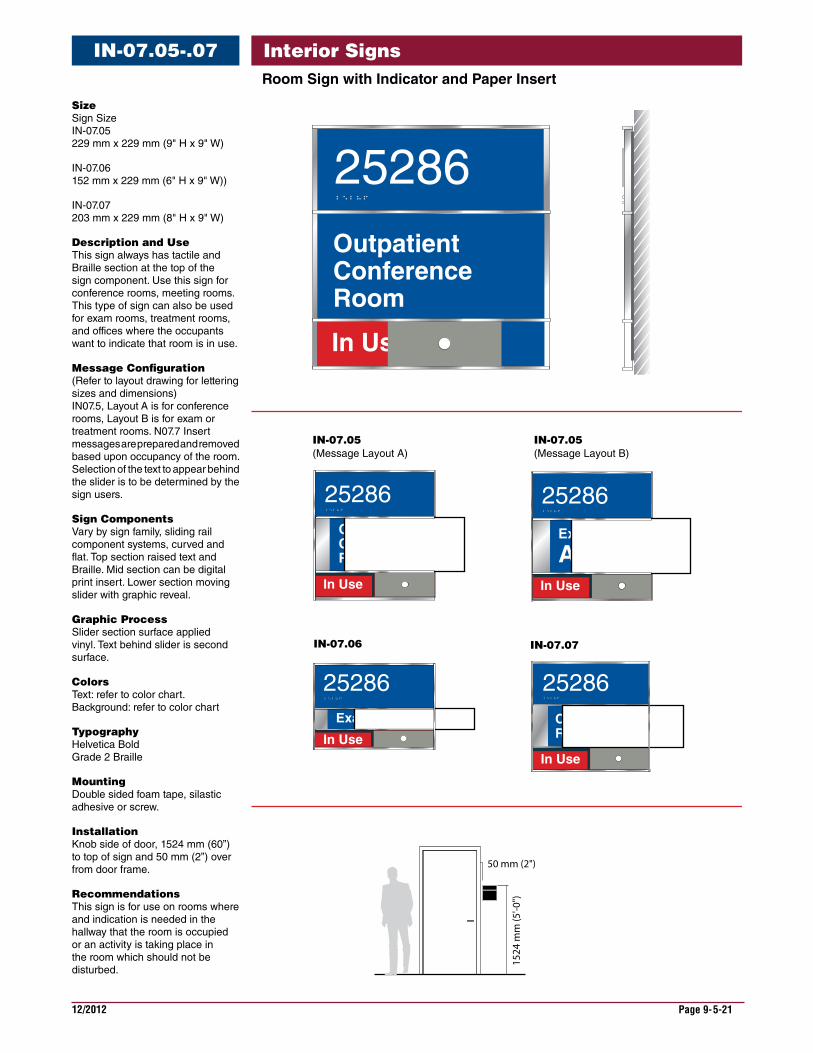
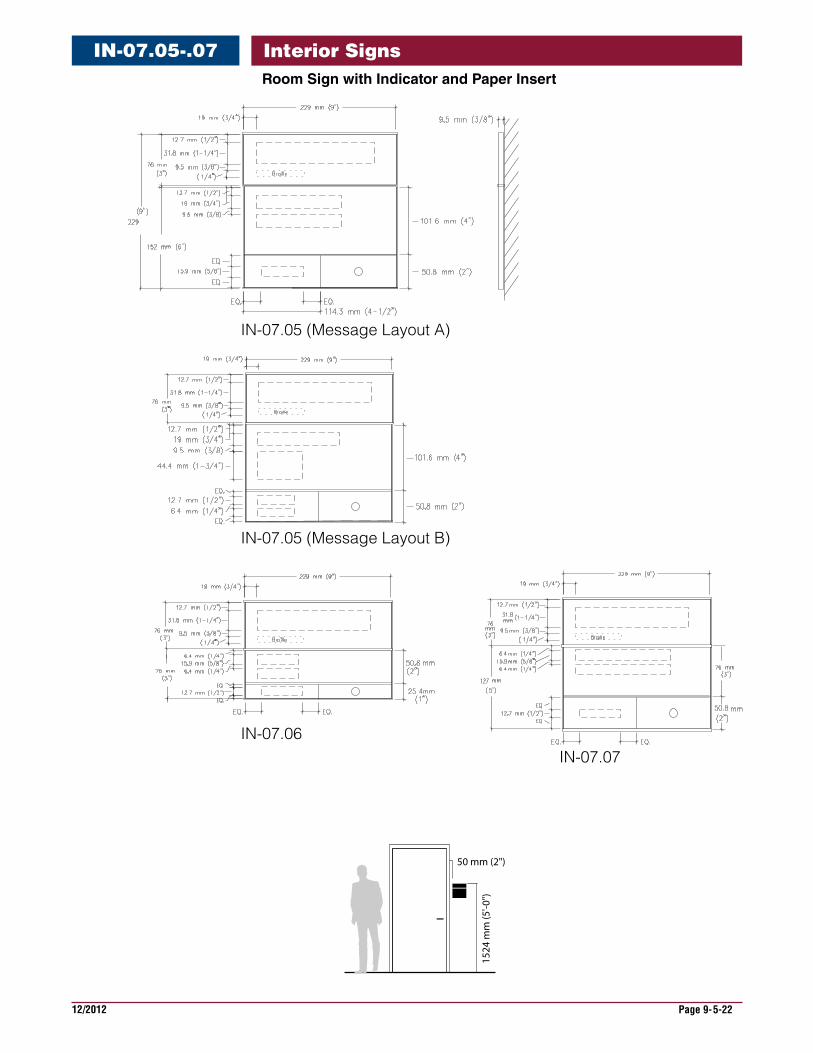
Interior SignsIN-07.05-.07RoomSignwithIndicatorandPaperInsert
Size Sign Size IN-07.05 229 mm x 229 mm (9" H x 9" W)
IN-07.06 152 mm x 229 mm (6" H x 9" W))
IN-07.07 203 mm x 229 mm (8" H x 9" W)
DescriptionandUse This sign always has tactile and Braille section at the top of the sign component. Use this sign for conference rooms, meeting rooms. This type of sign can also be used for exam rooms, treatment rooms, and offices where the occupants want to indicate that room is in use.
MessageConfiguration (Refer to layout drawing for lettering sizes and dimensions) IN07.5, Layout A is for conference rooms, Layout B is for exam or treatment rooms. N07.7 Insert messages are prepared and removed based upon occupancy of the room. Selection of the text to appear behind the slider is to be determined by the sign users.
SignComponents Vary by sign family, sliding rail component systems, curved and flat. Top section raised text and Braille. Mid section can be digital print insert. Lower section moving slider with graphic reveal.
GraphicProcess Slider section surface applied vinyl. Text behind slider is second surface.
Colors Text: refer to color chart. Background: refer to color chart
Typography Helvetica Bold Grade 2 Braille
Mounting Double sided foam tape, silastic adhesive or screw.
Installation Knob side of door, 1524 mm (60”) to top of sign and 50 mm (2”) over from door frame.
Recommendations This sign is for use on rooms where and indication is needed in the hallway that the room is occupied or an activity is taking place in the room which should not be disturbed.
IN-07.05 (Message Layout A)
IN-07.05 (Message Layout B)
IN-07.06 IN-07.07
50 mm (2")
1524
mm
(5'-0
")OutpatientConferenceRoom
In Use
In Use
Exam A
2528625286
2528625286
OutpatientConferenceRoom
In Use
2528625286
In Use
2528625286
Exam
A
ConferenceRoom
In Use
2528625286
12/2012 Page 9-5-22
Interior SignsIN-07.05-.07RoomSignwithIndicatorandPaperInsert
IN-07.05 (Message Layout A)
IN-07.05 (Message Layout B)
IN-07.06IN-07.07
50 mm (2")
1524
mm
(5'-0
")
12/2012 Page 9-5-23
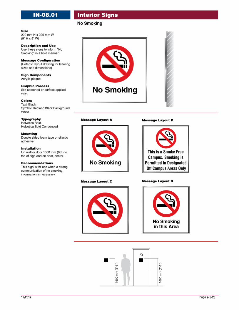
Interior SignsNoSmoking
IN-08.01
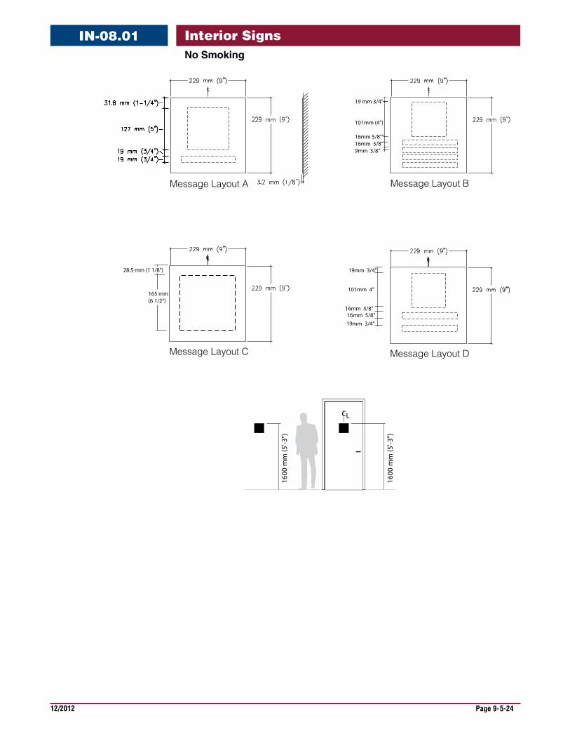
Size 229 mm H x 229 mm W (9" H x 9" W)
DescriptionandUse Use these signs to inform "No Smoking" in a bold manner.
MessageConfiguration (Refer to layout drawing for lettering sizes and dimensions)
SignComponents Acrylic plaque.
GraphicProcess Silk-screened or surface applied vinyl.
Colors Text: Black Symbol: Red and Black Background: White
Typography Helvetica Bold Helvetica Bold Condensed
Mounting Double sided foam tape or silastic adhesive.
Installation On wall or door 1600 mm (63") to top of sign and on door, center.
Recommendations This sign is for use when a strong communication of no smoking information is necessary.
Message Layout A
CL
1600
mm
(5'-3
")
1600
mm
(5'-3
")
No Smoking
No Smoking
This is a Smoke Free Campus. Smoking is
Permitted in Designated Off Campus Areas Only
Message Layout B
Message Layout C Message Layout D
No Smokingin this Area
12/2012 Page 9-5-24
Interior SignsNoSmoking
IN-08.01
Message Layout C
Message Layout A
28.5 mm (1 1/8")
165 mm(6 1/2")
Message Layout D
16mm 5/8”
19mm 3/4”
16mm 5/8”19mm 3/4”
101mm 4”
CL
1600
mm
(5'-3
")
1600
mm
(5'-3
")
Message Layout B
19 mm 3/4”
101mm (4”)
16mm 5/8“”16mm 5/8”9mm 3/8”
12/2012 Page 9-5-25
Interior Signs
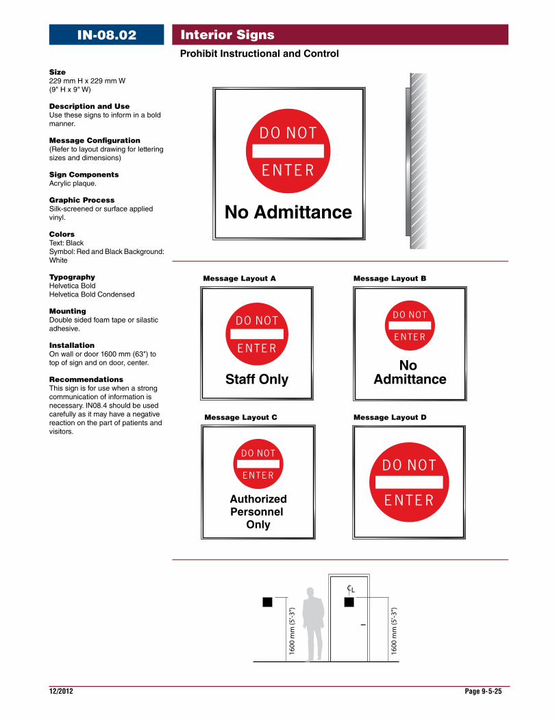
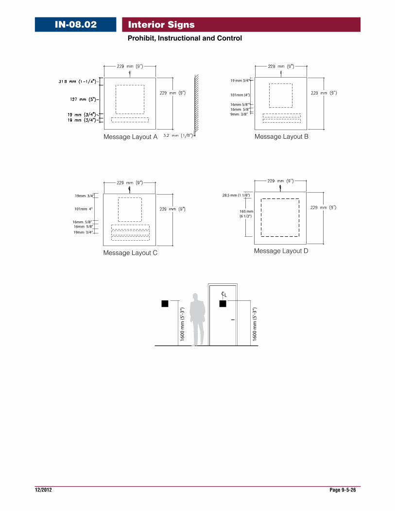
Size 229 mm H x 229 mm W (9" H x 9" W)
DescriptionandUse Use these signs to inform in a bold manner.
MessageConfiguration (Refer to layout drawing for lettering sizes and dimensions)
SignComponents Acrylic plaque.
GraphicProcess Silk-screened or surface applied vinyl.
Colors Text: Black Symbol: Red and Black Background: White
Typography Helvetica Bold Helvetica Bold Condensed
Mounting Double sided foam tape or silastic adhesive.
Installation On wall or door 1600 mm (63") to top of sign and on door, center.
Recommendations This sign is for use when a strong communication of information is necessary. IN08.4 should be used carefully as it may have a negative reaction on the part of patients and visitors.
ProhibitInstructionalandControl
IN-08.02
Message Layout BMessage Layout A
Message Layout C
Staff Only
CL
1600
mm
(5'-3
")
1600
mm
(5'-3
")
Message Layout D
AuthorizedPersonnel
Only
No Admittance
No Admittance
12/2012 Page 9-5-26
Interior SignsProhibit,InstructionalandControl
IN-08.02
Message Layout D
Message Layout A
28.5 mm (1 1/8")
165 mm(6 1/2")
Message Layout C
16mm 5/8”
19mm 3/4”
16mm 5/8”19mm 3/4”
101mm 4”
CL
1600
mm
(5'-3
")
1600
mm
(5'-3
")
Message Layout B
19 mm 3/4”
101mm (4”)
16mm 5/8“”16mm 5/8”9mm 3/8”

12/2012 Page 9-5-27
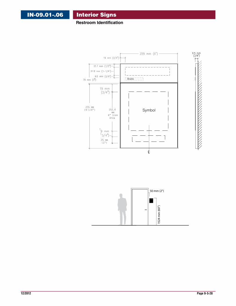
Interior SignsRestroomIdentification
IN-09.01-.06
Size 311 mm H x 229 mm W (12 1/4" H x 9" W)
DescriptionandUse Use these signs to inform with a symbol, tactile raised text and Braille.
MessageConfiguration (Refer to layout drawing for lettering sizes and dimensions)
SignComponents Vary by sign family, component systems, curved and flat. Top section raised text and Braille. Lower section to be raised graphic symbol.
GraphicProcess Tactile symbol and text with accompanying Braille.
Colors Text: refer to color chart. Background: refer to color chart
Typography Helvetica Bold Grade 2 Braille
Mounting Double sided foam tape or silastic adhesive.
Installation On wall or door 1524 mm (60") to top of sign and on door, center.
Recommendations These signs are for use to identify restrooms.
1524
mm
(60
")
50 mm (2")
Wall mounted
RESTROOM
242442A244
MEN
242442A244
WOMEN
242442A244
IN-09.06
RESTROOM
242442A244
IN-09.03IN-09.01 IN-09.02
MEN
242442A244
WOMEN
242442A244
IN-09.04 IN-09.05
MEN
242442A244
12/2012 Page 9-5-28
Interior SignsRestroomIdentification
IN-09.01-.06
152.4 mm
6” IconArea
235 mm (9-1/4”)
25 mm (1”)
1524
mm
(60"
)
50 mm (2")
Symbol
Braille
12/2012 Page 9-5-29
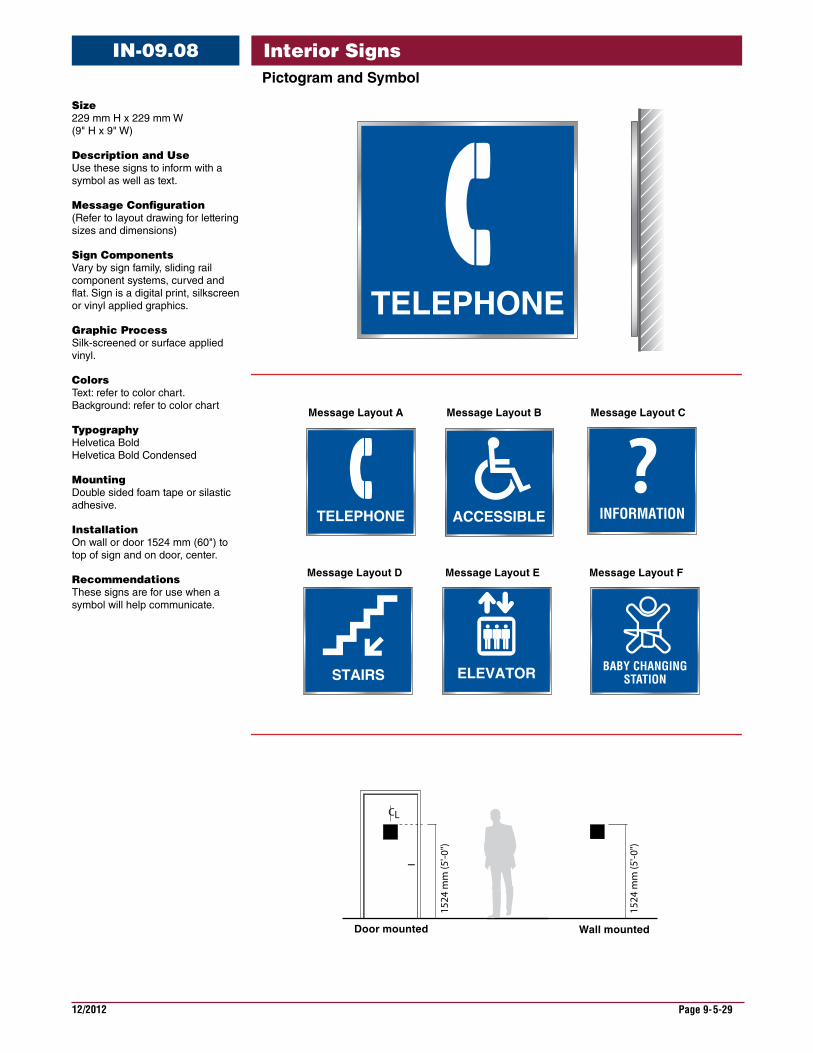
Interior SignsIN-09.08PictogramandSymbol
TELEPHONE ACCESSIBLE
CL
1524
mm
(5'-0
")
1524
mm
(5'-0
")
Door mounted Wall mounted
Message Layout C
STAIRS ELEVATOR
INFORMATION
BABY CHANGINGSTATION
TELEPHONE
Message Layout A Message Layout B
Message Layout FMessage Layout D Message Layout E
Size 229 mm H x 229 mm W (9" H x 9" W)
DescriptionandUse Use these signs to inform with a symbol as well as text.
MessageConfiguration (Refer to layout drawing for lettering sizes and dimensions)
SignComponents Vary by sign family, sliding rail component systems, curved and flat. Sign is a digital print, silkscreen or vinyl applied graphics.
GraphicProcess Silk-screened or surface applied vinyl.
Colors Text: refer to color chart. Background: refer to color chart
Typography Helvetica Bold Helvetica Bold Condensed
Mounting Double sided foam tape or silastic adhesive.
Installation On wall or door 1524 mm (60") to top of sign and on door, center.
Recommendations These signs are for use when a symbol will help communicate.
12/2012 Page 9-5-30
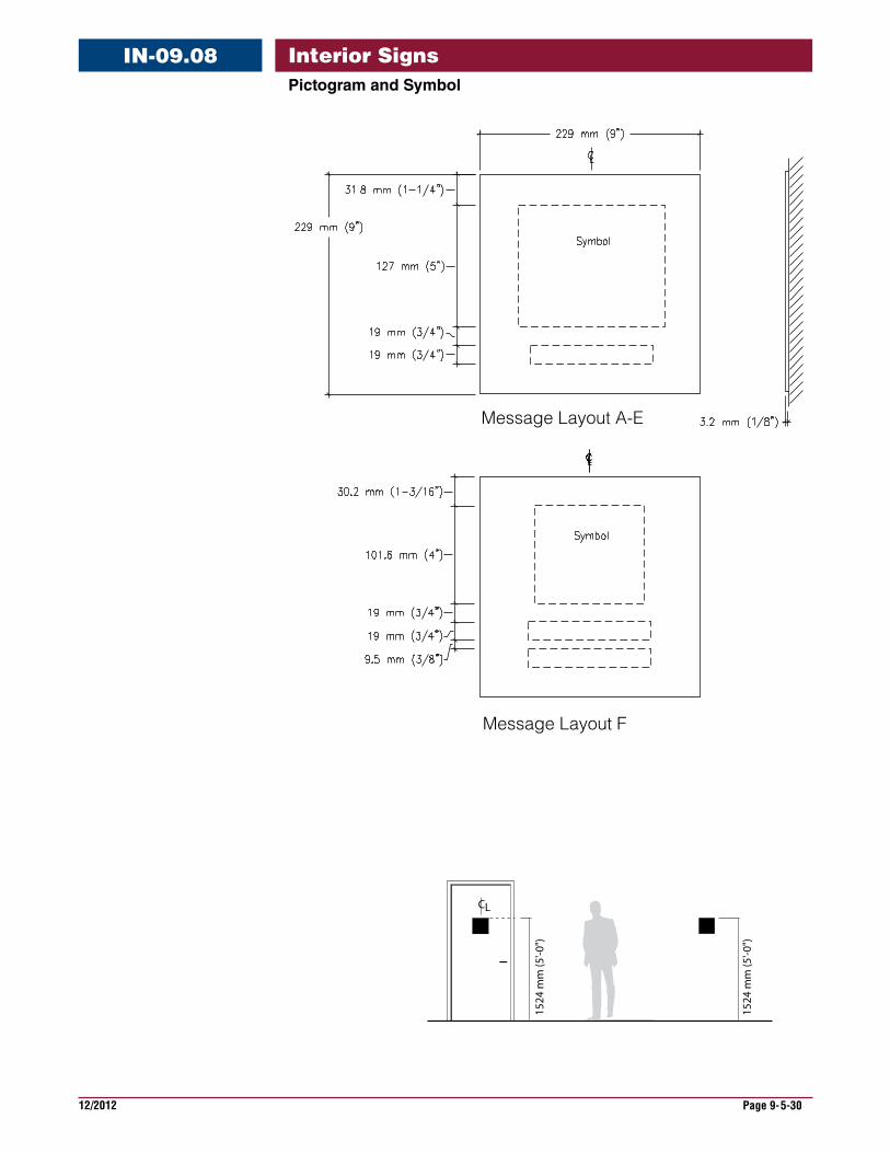
Interior SignsIN-09.08PictogramandSymbol
Message Layout A-E
Message Layout F
CL
1524
mm
(5'-0
")
1524
mm
(5'-0
")
12/2012 Page 9-5-31
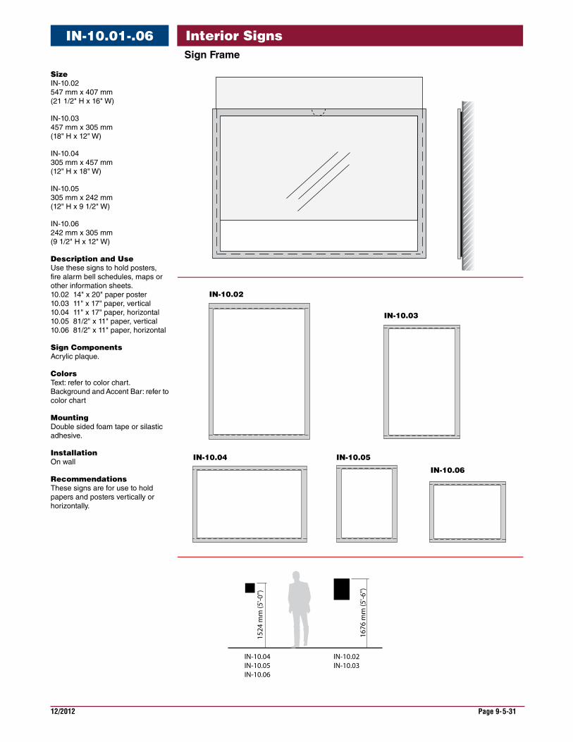
Interior SignsSignFrame
IN-10.01-.06
IN-10.02
IN-10.04 IN-10.05
IN-10.06
IN-10.03
1676
mm
(5'-6
")
1524
mm
(5'-0
")
IN-10.02IN-10.03
IN-10.04IN-10.05IN-10.06
Size IN-10.02 547 mm x 407 mm (21 1/2" H x 16" W)
IN-10.03 457 mm x 305 mm (18" H x 12" W)
IN-10.04 305 mm x 457 mm (12" H x 18" W)
IN-10.05 305 mm x 242 mm (12" H x 9 1/2" W)
IN-10.06 242 mm x 305 mm (9 1/2" H x 12" W)
DescriptionandUse Use these signs to hold posters, fire alarm bell schedules, maps or other information sheets. 10.02 14" x 20" paper poster 10.03 11" x 17" paper, vertical 10.04 11" x 17" paper, horizontal 10.05 81/2" x 11" paper, vertical 10.06 81/2" x 11" paper, horizontal
SignComponents Acrylic plaque.
Colors Text: refer to color chart. Background and Accent Bar: refer to color chart
Mounting Double sided foam tape or silastic adhesive.
Installation On wall
Recommendations These signs are for use to hold papers and posters vertically or horizontally.

12/2012 Page 9-5-32
Interior SignsSignFrame
IN-10.01-.06
1676
mm
(5'-6
")
1524
mm
(5'-0
")
IN-10.04
IN-10.02 IN-10.03
IN-10.05 IN-10.06

12/2012 Page 9-5-33
Interior SignsInformationalorInstructional
IN-11.01-.04
For PatientInformationPlease use telephones located at the information desk in the main lobby.
For YourInformationOjnf naleotj nalihlieaklndfa majroepa. Halweo nahia aneioaojoja marjap naohrasoow.
For YourInformationOjnf naleotj nalihlie
aklndfa majroepa.
Halweo nahia aneio
aojoja marjap naohr
asoow.
Fraoerjej nongini niorngi ni usdhonaoingonio rij n. Goaohr diohionn;dnjfa'opwej oijoan au ef esij ej kanfliohaoifhan. HAouhei feihfiia0t0 sjjji. Hajkseh ioawul abshrioa.IAhowrhihi auhfau aihof ainiaaoijwo abwiriougs. Kajwhr kkjgoaihwoaho. Jlaofn eijaj amwirjaawnapj anwkorjopa.
For Your Information
IN-11.01
IN-11.04
IN-11.02 IN-11.03
Lakeiea nahei naoiw anowh amwirj ajshraiwjrioan. Bakwoa iehaoi ksaw awejfaj naowurih eian. Amakej airhaoinfieao fniaaienfioa naiw aie aieh. O aoh aebfaui naieaiehaoih ahiw awioh eraponf aheioa aniowaawhaioh hai aw9u awiohroahfa.
Si usted es un paciente que esta recibiendo tratamiento por cualquier forma de cancer de la prostata, o antes de llevarse a cabo una biopsia para cancer de la prostata, se le urge a su medico y cirujano que le den un sumario escrito de metodos alternativos de tratamiento eficaz, segun la Seccion 1704.7 del Codigo de Salud y Seguridad de California.
Be Informed
1524
mm
(5'-0
")
IN-11.01IN-11.02IN-11.04
1676
mm
(5'-6
")
IN-11.03
Size IN-11.01 229 mm x 229 mm (9" H x 9" W)
IN-11.02 381 mm x 381 mm (15" H x 15" W)
IN-11.03 508 mm x 508 mm (20"H x 20"W)
IN-11.04 152 mm H x 152 mm W (6" H x 6" W)
DescriptionandUse Use this sign to communicate miscellaneous information.
MessageConfiguration (Refer to layout drawing for lettering sizes and dimensions) Layouts relate to the size and importance of message.
SignComponents Vary by sign family, sliding rail component systems, curved and flat. Can be digital print, silkscreen or vinyl applied graphics.
GraphicProcess Surface applied vinyl.
Colors Text: refer to color chart. Background and Accent Bar: refer to color chart
Typography Helvetica Bold
Mounting Double sided foam tape, silastic adhesive or screw.
Installation On wall
Recommendations These sign are for use to present brief general messages. Text should be limited to as few a words as possible. Long messages are generally not read.
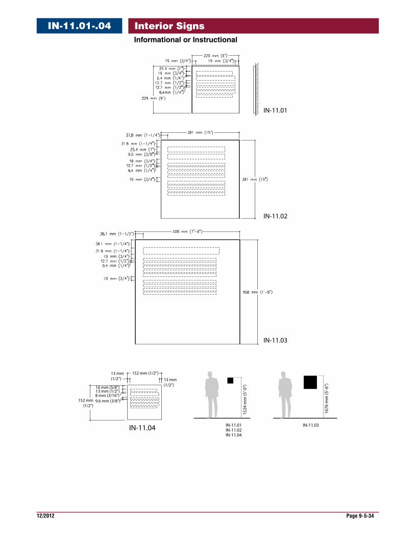
12/2012 Page 9-5-34
Interior SignsInformationalorInstructional
IN-11.01-.04
IN-11.01
IN-11.02
IN-11.03
13 mm (1/2”)
13 mm (1/2”)
152 mm (1/2”)
152 mm(1/2”)
IN-11.04
13 mm (1/2”)8 mm (3/16”)
16 mm (5/8”)
9.6 mm (3/8”)
1524
mm
(5'-0
")
IN-11.01IN-11.02IN-11.04
1676
mm
(5'-6
")
IN-11.03
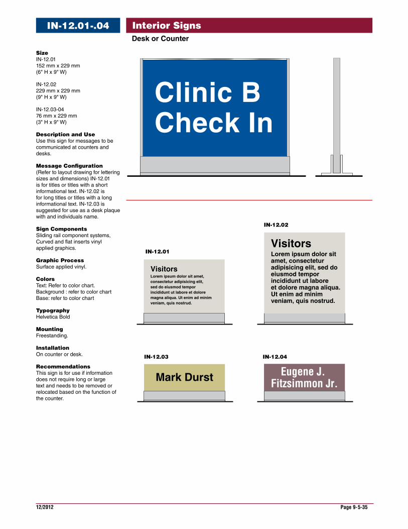
12/2012 Page 9-5-35
Interior SignsDeskorCounter
IN-12.01-.04
Mark Durst
Visitors
IN-12.03
IN-12.01
IN-12.02
Lorem ipsum dolor sit amet, consectetur adipisicing elit, sed do eiusmod tempor incididunt ut labore et dolore magna aliqua. Ut enim ad minim veniam, quis nostrud.
Visitors
Clinic B Check In
Eugene J. Fitzsimmon Jr.
IN-12.04
Lorem ipsum dolor sit amet, consectetur adipisicing elit, sed do eiusmod tempor incididunt ut labore et dolore magna aliqua. Ut enim ad minim veniam, quis nostrud.
Size IN-12.01 152 mm x 229 mm (6" H x 9" W)
IN-12.02 229 mm x 229 mm (9" H x 9" W)
IN-12.03-04 76 mm x 229 mm (3" H x 9" W)
DescriptionandUse Use this sign for messages to be communicated at counters and desks.
MessageConfiguration (Refer to layout drawing for lettering sizes and dimensions) IN-12.01 is for titles or titles with a short informational text. IN-12.02 is for long titles or titles with a long informational text. IN-12.03 is suggested for use as a desk plaque with and individuals name.
SignComponents Sliding rail component systems, Curved and flat inserts vinyl applied graphics.
GraphicProcess Surface applied vinyl.
Colors Text: Refer to color chart. Background : refer to color chart Base: refer to color chart
Typography Helvetica Bold
Mounting Freestanding.
Installation On counter or desk.
Recommendations This sign is for use if information does not require long or large text and needs to be removed or relocated based on the function of the counter.
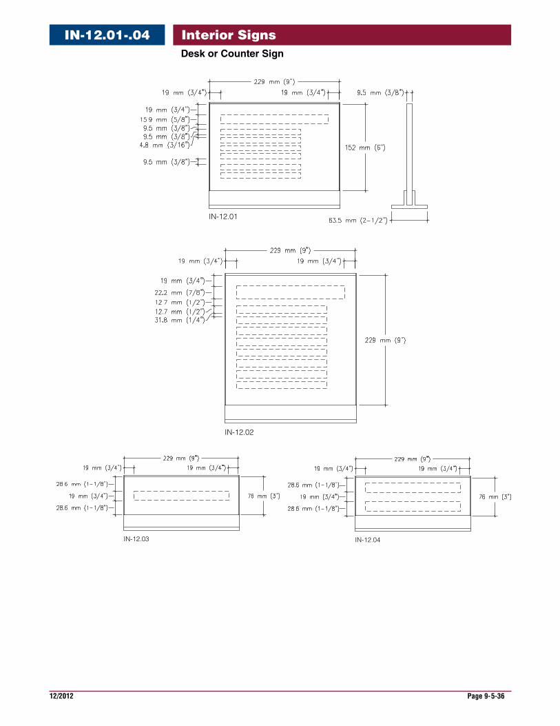
12/2012 Page 9-5-36
Interior SignsDeskorCounterSign
IN-12.01-.04
IN-12.01
IN-12.02
IN-12.03 IN-12.04
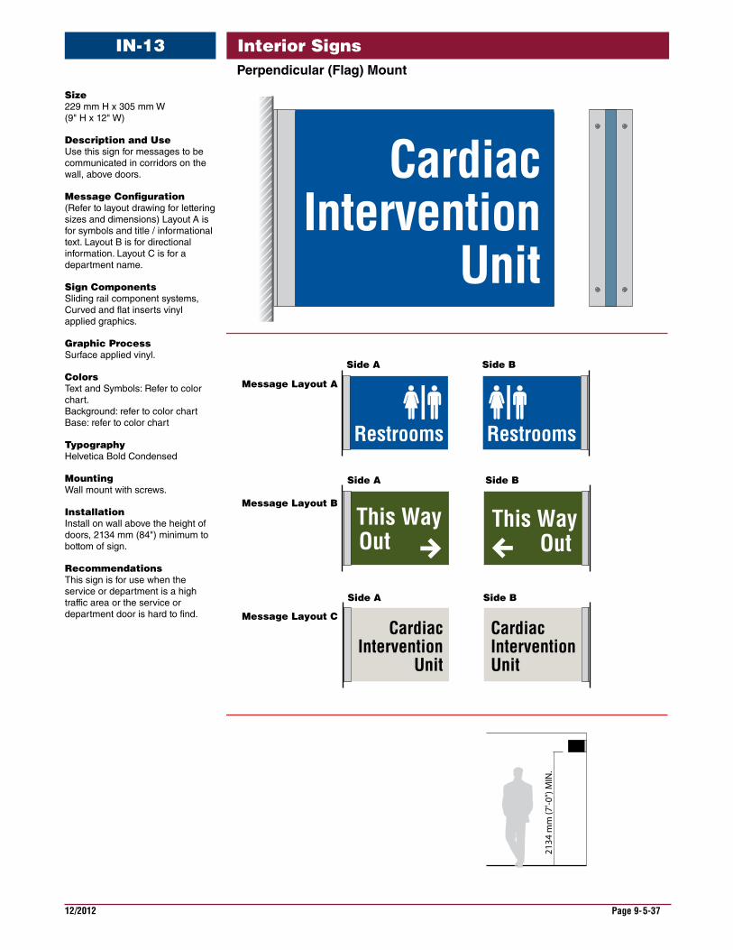
12/2012 Page 9-5-37
Interior SignsPerpendicular(Flag)Mount
IN-13
Message Layout B
Message Layout C
This WayOut
This WayOut
Side B
Side A Side B
2134
mm
(7'-0
") M
IN.
CardiacIntervention
Unit
CardiacIntervention
Unit
CardiacInterventionUnit
Side A
Side A Side B
Message Layout A
RestroomsRestrooms
Size 229 mm H x 305 mm W (9" H x 12" W)
DescriptionandUse Use this sign for messages to be communicated in corridors on the wall, above doors.
MessageConfiguration (Refer to layout drawing for lettering sizes and dimensions) Layout A is for symbols and title / informational text. Layout B is for directional information. Layout C is for a department name.
SignComponents Sliding rail component systems, Curved and flat inserts vinyl applied graphics.
GraphicProcess Surface applied vinyl.
Colors Text and Symbols: Refer to color chart. Background: refer to color chart Base: refer to color chart
Typography Helvetica Bold Condensed
Mounting Wall mount with screws.
Installation Install on wall above the height of doors, 2134 mm (84") minimum to bottom of sign.
Recommendations This sign is for use when the service or department is a high traffic area or the service or department door is hard to find.

12/2012 Page 9-5-38
Interior SignsPerpendicular(Flag)Mount
IN-13
2134
mm
(7'-0
") M
IN.
Message Layout A
Message Layout B
Message Layout C
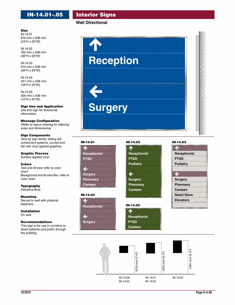
12/2012 Page 9-5-39
Interior SignsWallDirectional
IN-14.01-.05
Receptionist
PTSD
Podiatry
Surgery
Pharmacy
Canteen
Receptionist
PTSD
Podiatry
Surgery
Pharmacy
Canteen
Receptionist
PTSD
Surgery
Pharmacy
Canteen
Receptionist
Surgery
Receptionist
PTSD
Canteen
IN-14.01
IN-14.04
IN-14.05
IN-14.02 IN-14.03
Reception
Surgery
Retail Store
Elevators
IN-14.04IN-14.05
IN-14.01IN-14.02
IN-14.03
1676
mm
(5'-6
")
1829
mm
(6'-0
")
1981
mm
(6'-6
")
Size IN-14.01 610 mm x 508 mm (24"H x 20"W)
IN-14.02 762 mm x 508 mm (30"H x 20"W)
IN-14.03 914 mm x 508 mm (36"H x 20"W)
IN-14.04 457 mm x 508 mm (18"H x 20"W)
IN-14.05 305 mm x 508 mm (12"H x 20"W)
SignUseandApplication Use this sign for directional information.
MessageConfiguration (Refer to layout drawing for lettering sizes and dimensions)
SignComponents Vary by sign family, sliding rail component systems, curved and flat with vinyl applied graphics.
GraphicProcess Surface applied vinyl.
Colors Text and Arrows: refer to color chart. Background and Accent Bar: refer to color chart
Typography Helvetica Bold
Mounting Secure to wall with physical fasteners.
Installation On wall.
Recommendations This sign is for use in corridors to direct patients and public through the building.
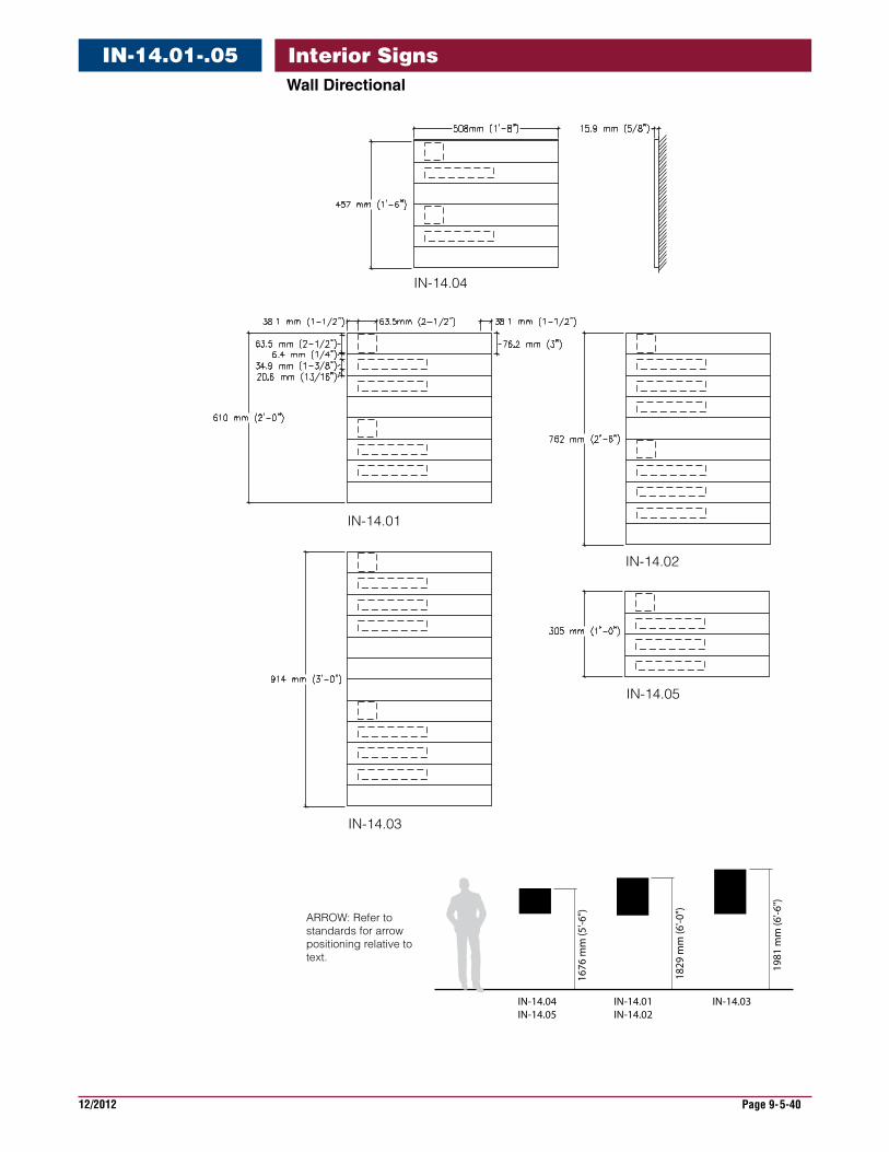
12/2012 Page 9-5-40
Interior SignsWallDirectional
IN-14.01-.05
IN-14.04IN-14.05
IN-14.01IN-14.02
IN-14.03
1676
mm
(5'-6
")
1829
mm
(6'-0
")
1981
mm
(6'-6
")
IN-14.04
IN-14.01
IN-14.02
IN-14.03
IN-14.05
ARROW: Refer tostandards for arrowpositioning relative totext.
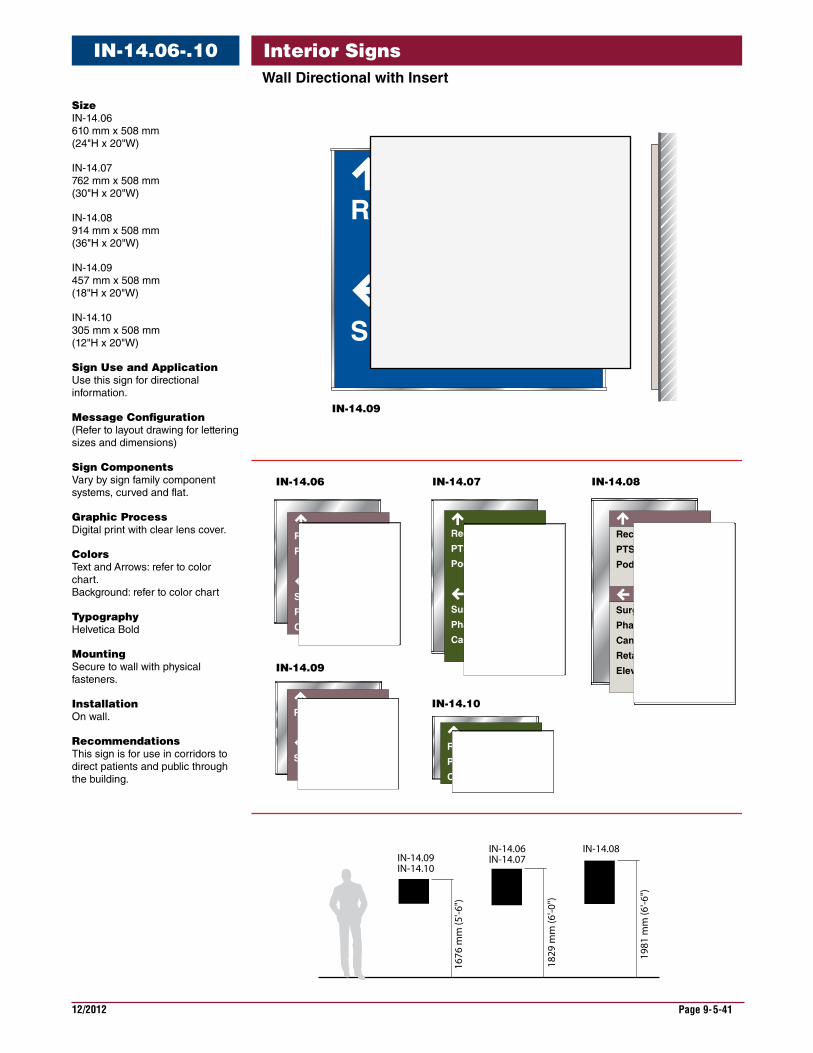
12/2012 Page 9-5-41
Interior SignsWallDirectionalwithInsert
IN-14.06-.10
Size IN-14.06 610 mm x 508 mm (24"H x 20"W)
IN-14.07 762 mm x 508 mm (30"H x 20"W)
IN-14.08 914 mm x 508 mm (36"H x 20"W)
IN-14.09 457 mm x 508 mm (18"H x 20"W)
IN-14.10 305 mm x 508 mm (12"H x 20"W)
SignUseandApplication Use this sign for directional information.
MessageConfiguration (Refer to layout drawing for lettering sizes and dimensions)
SignComponents Vary by sign family component systems, curved and flat.
GraphicProcess Digital print with clear lens cover.
Colors Text and Arrows: refer to color chart. Background: refer to color chart
Typography Helvetica Bold
Mounting Secure to wall with physical fasteners.
Installation On wall.
Recommendations This sign is for use in corridors to direct patients and public through the building.
IN-14.09
IN-14.06
IN-14.10
IN-14.07 IN-14.08
Reception
Surgery
Receptionist
PTSD
Podiatry
Surgery
Pharmacy
Canteen
Retail Store
Elevators
IN-14.09IN-14.10
IN-14.06IN-14.07
IN-14.08
1676
mm
(5'-6
")
1829
mm
(6'-0
")
1981
mm
(6'-6
")
Receptionist
PTSD
Surgery
Pharmacy
Canteen
Receptionist
PTSD
Podiatry
Surgery
Pharmacy
Canteen
Receptionist
SurgeryReceptionist
PTSD
Canteen
IN-14.09
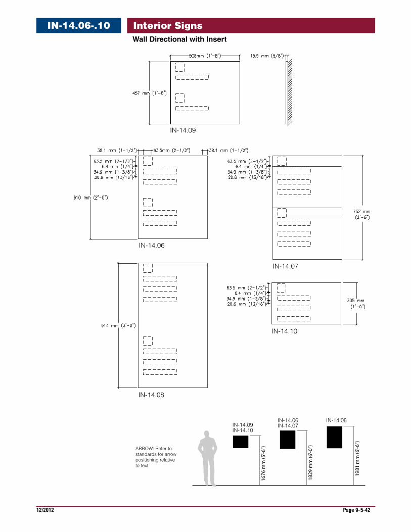
12/2012 Page 9-5-42
Interior SignsWallDirectionalwithInsert
IN-14.06-.10
IN-14.07
IN-14.10
IN-14.06
IN-14.08
IN-14.09
IN-14.09IN-14.10
IN-14.06IN-14.07
IN-14.08
1676
mm
(5'-6
")
1829
mm
(6'-0
")
1981
mm
(6'-6
")
ARROW: Refer to standards for arrowpositioning relative to text.
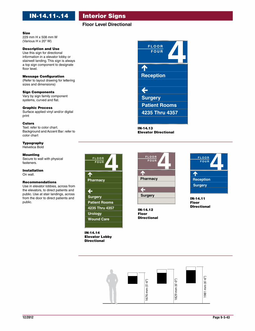
12/2012 Page 9-5-43
Interior SignsFloorLevelDirectional
IN-14.11-.14
Size 229 mm H x 508 mm W (Various H x 20" W)
DescriptionandUse Use this sign for directional information in a elevator lobby or stairwell landing. This sign is always a top sign component to designate floor level.
MessageConfiguration (Refer to layout drawing for lettering sizes and dimensions)
SignComponents Vary by sign family component systems, curved and flat.
GraphicProcess Surface applied vinyl and/or digital print
Colors Text: refer to color chart. Background and Accent Bar: refer to color chart
Typography Helvetica Bold
Mounting Secure to wall with physical fasteners.
Installation On wall.
Recommendations Use in elevator lobbies, across from the elevators, to direct patients and public. Use at stair landings, across from the door to direct patients and public.
1676
mm
(5'-6
")
1829
mm
(6'-0
")
1981
mm
(6'-6
")
4F L O O RF O U R
Pharmacy
Surgery
IN-14.12FloorDIrectional
4F L O O RF O U R
Reception
SurgeryPatient Rooms4235 Thru 4357
IN-14.13Elevator DIrectional
4F L O O RF O U R
Pharmacy
Surgery
Patient Rooms
4235 Thru 4357
Urology
Wound Care
IN-14.14Elevator LobbyDirectional
4F L O O RF O U R
Reception
Surgery
IN-14.11Floor DIrectional

12/2012 Page 9-5-44
Interior SignsIN-14.11-.14
IN-14.11
IN-14.12
IN-14.14IN-14.13
1676
mm
(5'-6
")
1829
mm
(6'-0
")
1981
mm
(6'-6
")
ARROW: Refer to standards for arrowpositioning relative to text.
IN-14.11
IN-14.12IN-14.13
IN-14.14
FloorLevelDirectional
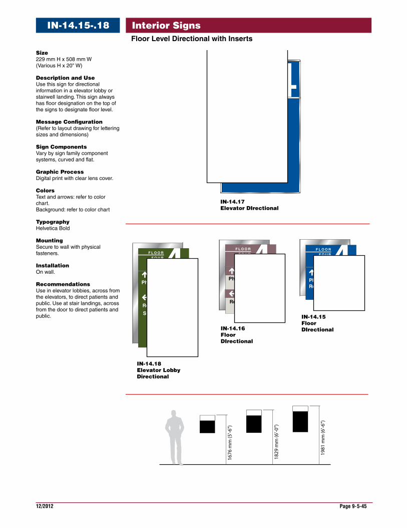
12/2012 Page 9-5-45
Interior SignsIN-14.15-.18FloorLevelDirectionalwithInserts
Size 229 mm H x 508 mm W (Various H x 20" W)
DescriptionandUse Use this sign for directional information in a elevator lobby or stairwell landing. This sign always has floor designation on the top of the signs to designate floor level.
MessageConfiguration (Refer to layout drawing for lettering sizes and dimensions)
SignComponents Vary by sign family component systems, curved and flat.
GraphicProcess Digital print with clear lens cover.
Colors Text and arrows: refer to color chart. Background: refer to color chart
Typography Helvetica Bold
Mounting Secure to wall with physical fasteners.
Installation On wall.
Recommendations Use in elevator lobbies, across from the elevators, to direct patients and public. Use at stair landings, across from the door to direct patients and public.
F L O O RF O U R
IN-14.16FloorDIrectional
IN-14.17Elevator DIrectional
Pharmacy
IN-14.18Elevator LobbyDirectional
IN-14.15Floor DIrectional
Reception
Surgery
F L O O RF O U R
Pharmacy
Reception
F L O O RF O U R
PharmacyReception
4F L O O RF O U R
Reception
SurgeryPatient Rooms4235 Thru 4357
1676
mm
(5'-6
")
1829
mm
(6'-0
")
1981
mm
(6'-6
")
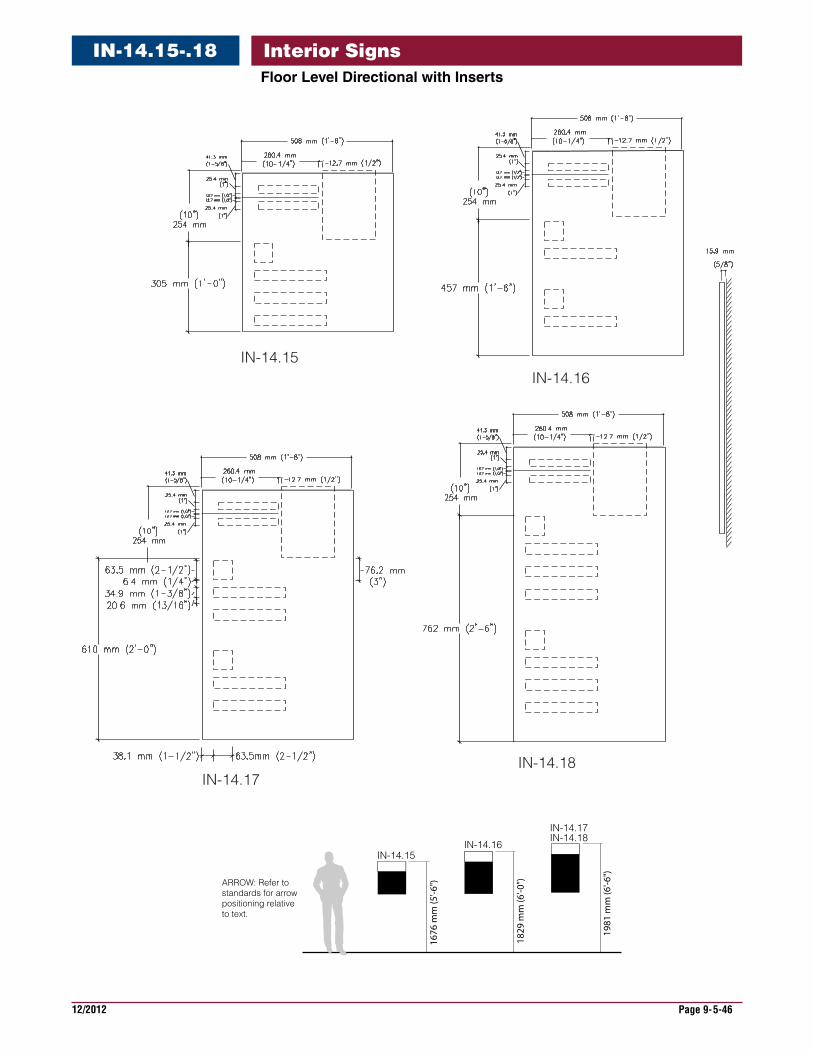
12/2012 Page 9-5-46
Interior SignsIN-14.15-.18FloorLevelDirectionalwithInserts
IN-14.15IN-14.16
IN-14.18IN-14.17
ARROW: Refer to standards for arrowpositioning relative to text.
1676
mm
(5'-6
")
1829
mm
(6'-0
")
1981
mm
(6'-6
")
IN-14.15IN-14.16
IN-14.17IN-14.18
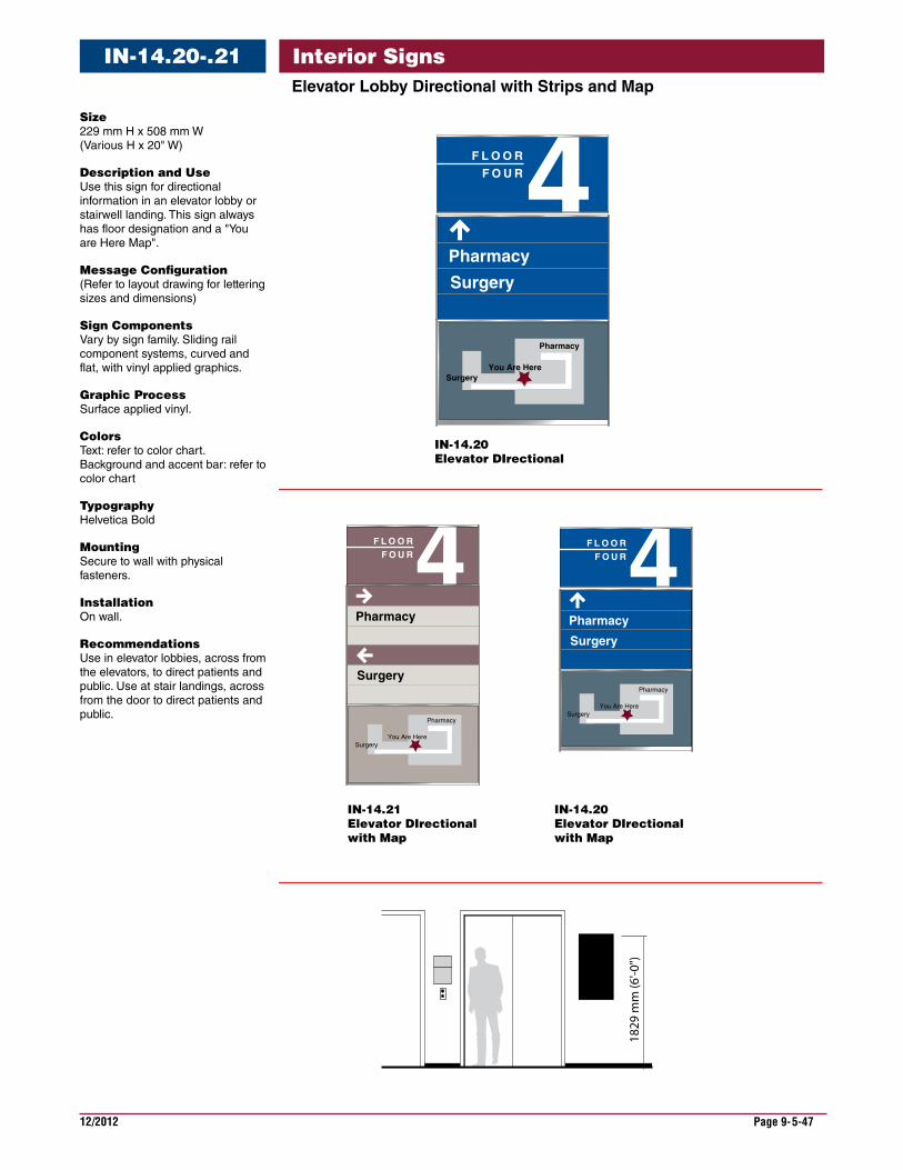
12/2012 Page 9-5-47
Interior SignsElevatorLobbyDirectionalwithStripsandMap
IN-14.20-.21
Size 229 mm H x 508 mm W (Various H x 20" W)
DescriptionandUse Use this sign for directional information in an elevator lobby or stairwell landing. This sign always has floor designation and a "You are Here Map".
MessageConfiguration (Refer to layout drawing for lettering sizes and dimensions)
SignComponents Vary by sign family. Sliding rail component systems, curved and flat, with vinyl applied graphics.
GraphicProcess Surface applied vinyl.
Colors Text: refer to color chart. Background and accent bar: refer to color chart
Typography Helvetica Bold
Mounting Secure to wall with physical fasteners.
Installation On wall.
Recommendations Use in elevator lobbies, across from the elevators, to direct patients and public. Use at stair landings, across from the door to direct patients and public.
IN-14.20Elevator DIrectional
4F L O O RF O U R
Pharmacy
Surgery
4F L O O RF O U R
Pharmacy
Surgery
IN-14.21Elevator DIrectionalwith Map
IN-14.20Elevator DIrectionalwith Map
You Are HereSurgery
Pharmacy
You Are HereSurgery
Pharmacy
4F L O O RF O U R
Pharmacy
Surgery
You Are HereSurgery
Pharmacy
182
9 m
m (6
'-0")
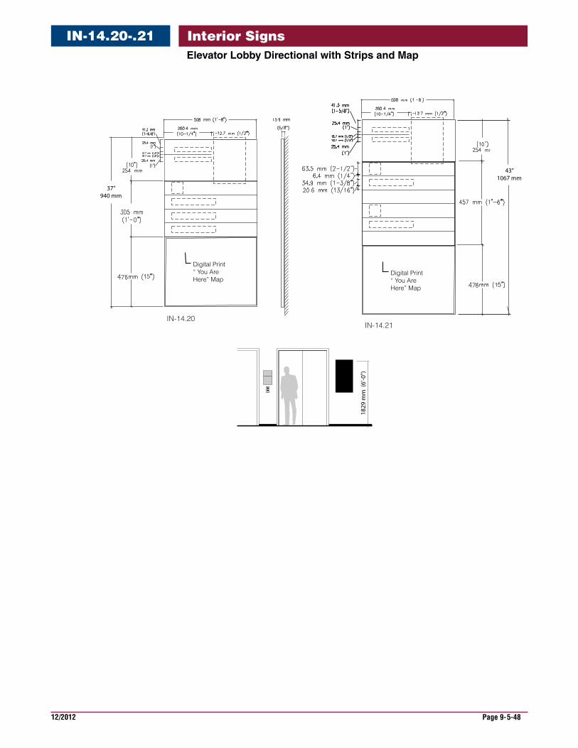
12/2012 Page 9-5-48
Interior Signs
IN-14.21
Digital Print“ You Are Here” Map
43” 1067 mm
IN-14.20
Digital Print“ You Are Here” Map
37” 940 mm
1829
mm
(6'
-0")
ElevatorLobbyDirectionalwithStripsandMap
IN-14.20-.21
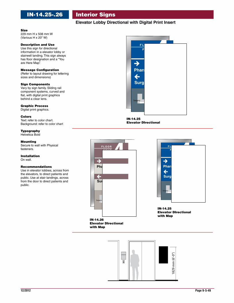
12/2012 Page 9-5-49
Interior SignsElevatorLobbyDirectionalwithDigitalPrintInsert
IN-14.25-.26
Size 229 mm H x 508 mm W (Various H x 20" W)
DescriptionandUse Use this sign for directional information in a elevator lobby or stairwell landing. This sign always has floor designation and a “You are Here Map”.
MessageConfiguration (Refer to layout drawing for lettering sizes and dimensions)
SignComponents Vary by sign family. Sliding rail component systems, curved and flat, with digital print graphics behind a clear lens.
GraphicProcess Digital print graphics.
Colors Text: refer to color chart. Background: refer to color chart
Typography Helvetica Bold
Mounting Secure to wall with Physical fasteners.
Installation On wall.
Recommendations Use in elevator lobbies, across from the elevators, to direct patients and public. Use at stair landings, across from the door to direct patients and public.
IN-14.25Elevator DIrectional
IN-14.26Elevator DIrectionalwith Map
IN-14.25Elevator DIrectionalwith Map
182
9 m
m (6
'-0")
F L O O RF O U R4
Pharmacy
Surgery
You Are HereSurgery
Pharmacy
F L O O RF O U R4
Pharmacy
Surgery
You Are HereSurgery
Pharmacy
F L O O RF O U R4
Pharmacy
Surgery
You Are HereSurgery
Pharmacy

12/2012 Page 9-5-50
Interior SignsElevatorLobbyDirectionalwithDigitalPrintInsert
IN-14.25-.26
IN-14.25
IN-14.26
Digital Print“You Are Here” Map
Digital Print“You Are Here” Map
43” 1067 mm
37” 940 mm
1829
mm
(6'-0
")
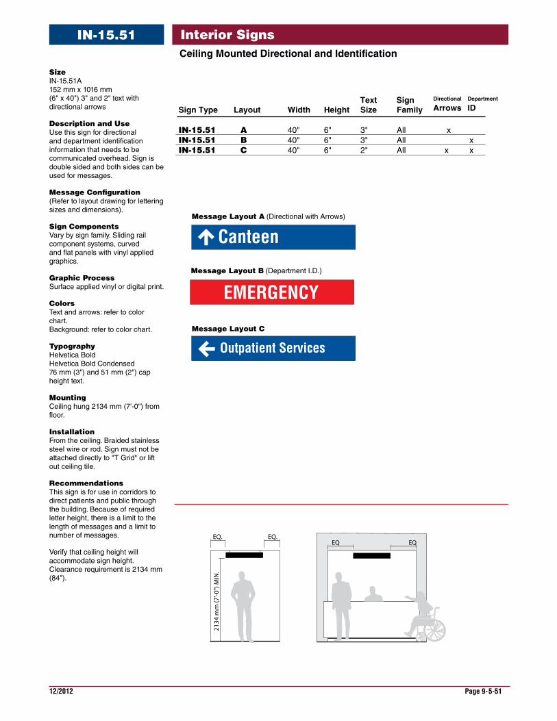
12/2012 Page 9-5-51
Interior SignsCeilingMountedDirectionalandIdentification
IN-15.51
Size IN-15.51A 152 mm x 1016 mm (6" x 40") 3" and 2" text with directional arrows
DescriptionandUse Use this sign for directional and department identification information that needs to be communicated overhead. Sign is double sided and both sides can be used for messages.
MessageConfiguration (Refer to layout drawing for lettering sizes and dimensions).
SignComponents Vary by sign family. Sliding rail component systems, curved and flat panels with vinyl applied graphics.
GraphicProcess Surface applied vinyl or digital print.
Colors Text and arrows: refer to color chart. Background: refer to color chart.
Typography Helvetica Bold Helvetica Bold Condensed 76 mm (3") and 51 mm (2") cap height text.
Mounting Ceiling hung 2134 mm (7'-0") from floor.
Installation From the ceiling. Braided stainless steel wire or rod. Sign must not be attached directly to "T Grid" or lift out ceiling tile.
Recommendations This sign is for use in corridors to direct patients and public through the building. Because of required letter height, there is a limit to the length of messages and a limit to number of messages.
Verify that ceiling height will accommodate sign height. Clearance requirement is 2134 mm (84").
Message Layout B (Department I.D.)
EMERGENCY
CanteenMessage Layout A (Directional with Arrows)
EQ. EQ.
2134
mm
(7'-0
") M
IN.
EQ EQ
Message Layout C
Outpatient Services
Sign Type Layout Width Height Size Family
IN-15.51 A 40" 6" 3" All xIN-15.51 B 40" 6" 3" All xIN-15.51 C 40" 6" 2" All x x
Text Sign Department
IDDirectional
Arrows
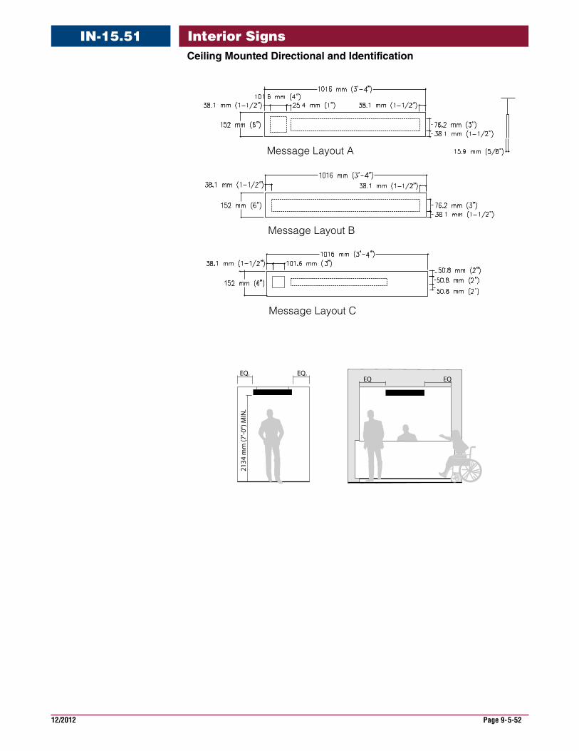
12/2012 Page 9-5-52
Interior SignsCeilingMountedDirectionalandIdentification
IN-15.51
Message Layout A
Message Layout B
Message Layout C
EQ. EQ.
2134
mm
(7'-0
") M
IN.
EQ EQ
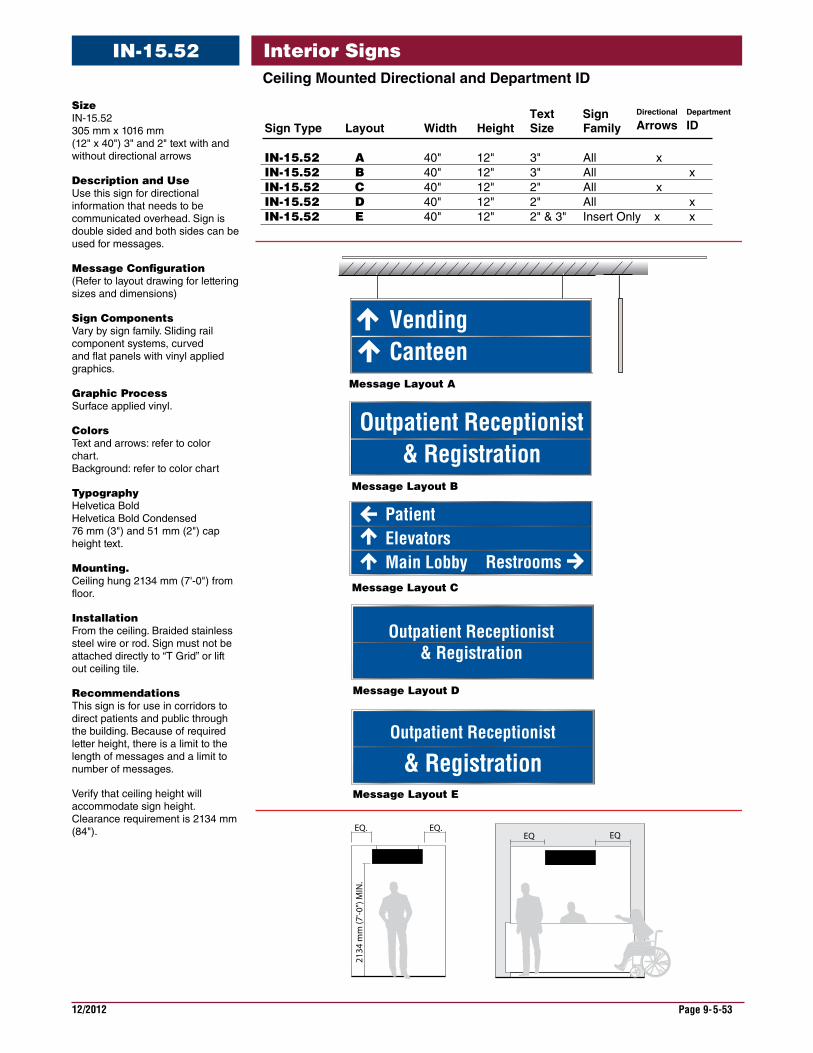
12/2012 Page 9-5-53
Interior SignsCeilingMountedDirectionalandDepartmentID
IN-15.52
Message Layout D
Message Layout E
EQ. EQ.
2134
mm
(7'-0
") M
IN.
Message Layout A
EQ EQ
Outpatient Receptionist& Registration
PatientElevatorsMain Lobby
Outpatient Receptionist& Registration
Restrooms
VendingCanteen
Message Layout B
Message Layout C
Outpatient Receptionist
& Registration
Sign Type Layout Width Height Size Family
IN-15.52 A 40" 12" 3" All xIN-15.52 B 40" 12" 3" All xIN-15.52 C 40" 12" 2" All x IN-15.52 D 40" 12" 2" All xIN-15.52 E 40" 12" 2" & 3" Insert Only x x
Text Sign Department
IDDirectional
Arrows
Size IN-15.52 305 mm x 1016 mm (12" x 40") 3" and 2" text with and without directional arrows
DescriptionandUse Use this sign for directional information that needs to be communicated overhead. Sign is double sided and both sides can be used for messages.
MessageConfiguration (Refer to layout drawing for lettering sizes and dimensions)
SignComponents Vary by sign family. Sliding rail component systems, curved and flat panels with vinyl applied graphics.
GraphicProcess Surface applied vinyl.
Colors Text and arrows: refer to color chart. Background: refer to color chart
Typography Helvetica Bold Helvetica Bold Condensed 76 mm (3") and 51 mm (2") cap height text.
Mounting. Ceiling hung 2134 mm (7'-0") from floor.
Installation From the ceiling. Braided stainless steel wire or rod. Sign must not be attached directly to “T Grid” or lift out ceiling tile.
Recommendations This sign is for use in corridors to direct patients and public through the building. Because of required letter height, there is a limit to the length of messages and a limit to number of messages.
Verify that ceiling height will accommodate sign height. Clearance requirement is 2134 mm (84").
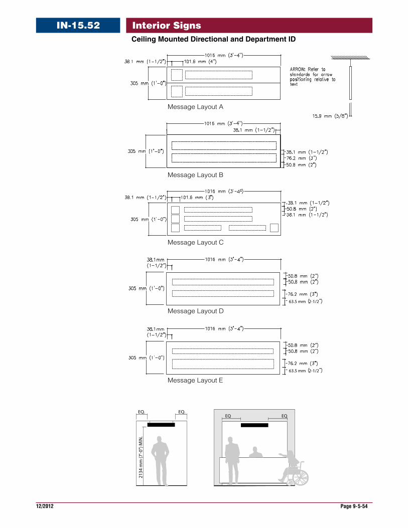
12/2012 Page 9-5-54
Interior SignsIN-15.52CeilingMountedDirectionalandDepartmentID
Message Layout A
Message Layout B
Message Layout C
Message Layout D
Message Layout E
63.5 mm 2-1/2
EQ. EQ.
2134
mm
(7'-0
") M
IN.
EQ EQ
63.5 mm 2-1/2
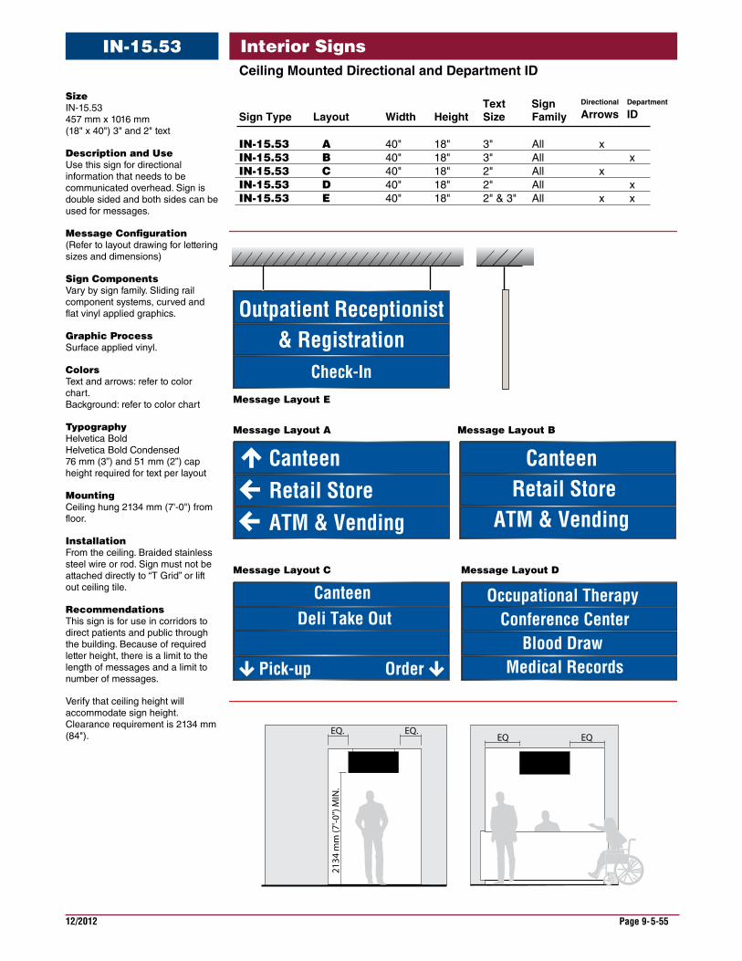
12/2012 Page 9-5-55
Interior SignsIN-15.53CeilingMountedDirectionalandDepartmentID
EQ. EQ.
2134
mm
(7'-0
") M
IN.
EQ EQ
Sign Type Layout Width Height Size Family
IN-15.53 A 40" 18" 3" All xIN-15.53 B 40" 18" 3" All xIN-15.53 C 40" 18" 2" All x IN-15.53 D 40" 18" 2" All xIN-15.53 E 40" 18" 2" & 3" All x x
Text Sign Department
IDDirectional
Arrows
Message Layout D
Message Layout E
Retail StoreATM & Vending
Canteen
Pick-up Order
Canteen Retail Store
ATM & Vending
Occupational Therapy Conference Center
Blood Draw Medical Records
Outpatient Receptionist& Registration
Check-In
Canteen Deli Take Out
Message Layout A Message Layout B
Message Layout C
Size IN-15.53 457 mm x 1016 mm (18" x 40") 3" and 2" text
DescriptionandUse Use this sign for directional information that needs to be communicated overhead. Sign is double sided and both sides can be used for messages.
MessageConfiguration (Refer to layout drawing for lettering sizes and dimensions)
SignComponents Vary by sign family. Sliding rail component systems, curved and flat vinyl applied graphics.
GraphicProcess Surface applied vinyl.
Colors Text and arrows: refer to color chart. Background: refer to color chart
Typography Helvetica Bold Helvetica Bold Condensed 76 mm (3”) and 51 mm (2”) cap height required for text per layout
Mounting Ceiling hung 2134 mm (7'-0") from floor.
Installation From the ceiling. Braided stainless steel wire or rod. Sign must not be attached directly to “T Grid” or lift out ceiling tile.
Recommendations This sign is for use in corridors to direct patients and public through the building. Because of required letter height, there is a limit to the length of messages and a limit to number of messages.
Verify that ceiling height will accommodate sign height. Clearance requirement is 2134 mm (84").
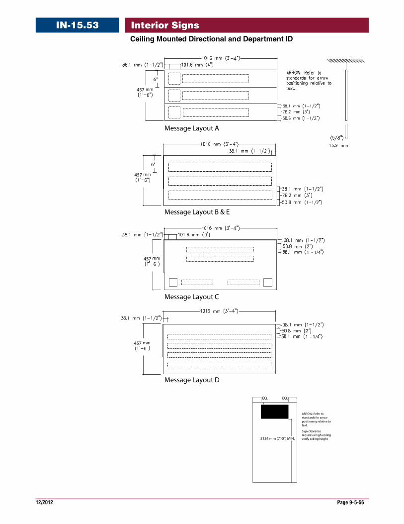
12/2012 Page 9-5-56
Interior SignsIN-15.53CeilingMountedDirectionalandDepartmentID
Message Layout A
Message Layout B & E
Message Layout C
Message Layout D
457
6"
457
6"
4571 - 1/4
4571 - 1/4
Sign clearance requires a high ceilingverify ceiling height
ARROW: Refer tostandards for arrow positioning relative totext.
2134 mm (7'-0") MIN.
EQ. EQ.
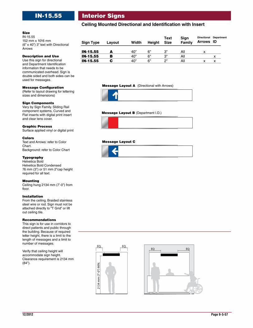
12/2012 Page 9-5-57
Interior SignsIN-15.55CeilingMountedDirectionalandIdentificationwithInsert
Size IN-15.55 152 mm x 1016 mm (6” x 40”) 3” text with Directional Arrows
DescriptionandUse Use this sign for directional and Department Identification information that needs to be communicated overhead. Sign is double sided and both sides can be used for messages.
MessageConfiguration (Refer to layout drawing for lettering sizes and dimensions)
SignComponents Vary by Sign Family. Sliding Rail component systems, Curved and Flat inserts with digital print insert and clear lens cover.
GraphicProcess Surface applied vinyl or digital print
Colors Text and Arrows: refer to Color Chart. Background: refer to Color Chart
Typography Helvetica Bold Helvetica Bold Condensed 76 mm (3") or 51 mm 2"cap height required for all text.
Mounting Ceiling hung 2134 mm (7’-0”) from floor.
Installation From the ceiling. Braided stainless steel wire or rod. Sign must not be attached directly to “T Grid” or lift out ceiling tile.
Recommendations This sign is for use in corridors to direct patients and public through the building. Because of required letter height, there is a limit to the length of messages and a limit to number of messages.
Verify that ceiling height will accommodate sign height. Clearance requirement is 2134 mm (84").
CanteenMessage Layout A (Directional with Arrows)
EQ. EQ.
2134
mm
(7'-0
") M
IN.
EQ EQ
Message Layout C
Canteen
EMERGENCY
Outpatient Services
Message Layout B (Department I.D.)
Sign Type Layout Width Height Size Family
IN-15.55 A 40" 6" 3" All xIN-15.55 B 40" 6" 3" All xIN-15.55 C 40" 6" 2" All x x
Text Sign Department
IDDirectional
Arrows
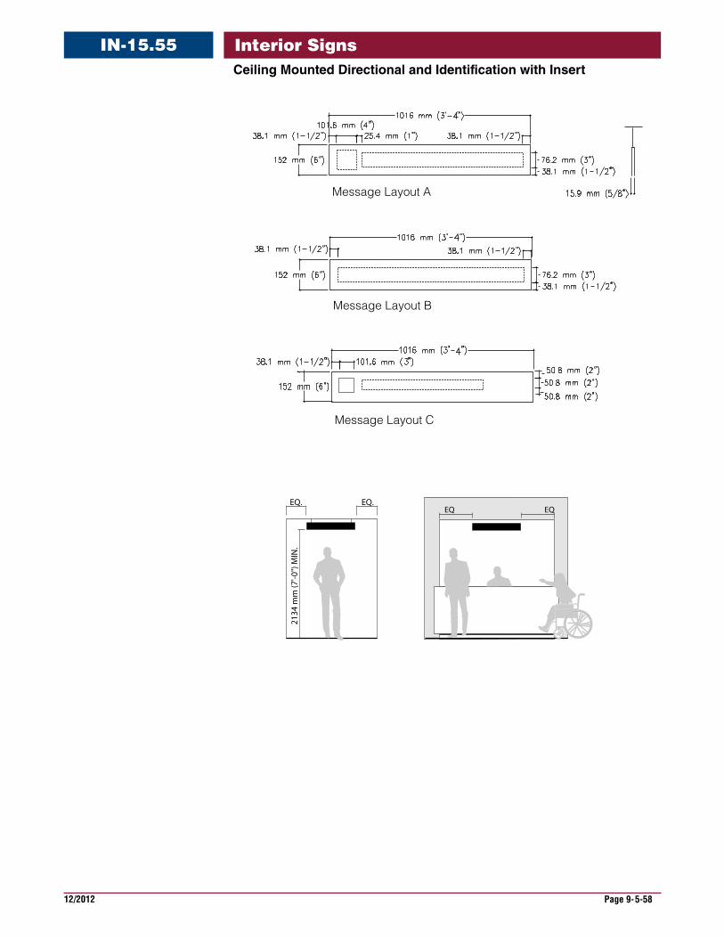
12/2012 Page 9-5-58
Interior SignsIN-15.55CeilingMountedDirectionalandIdentificationwithInsert
Message Layout A
Message Layout B
Message Layout C
EQ. EQ.
2134
mm
(7'-0
") M
IN.
EQ EQ
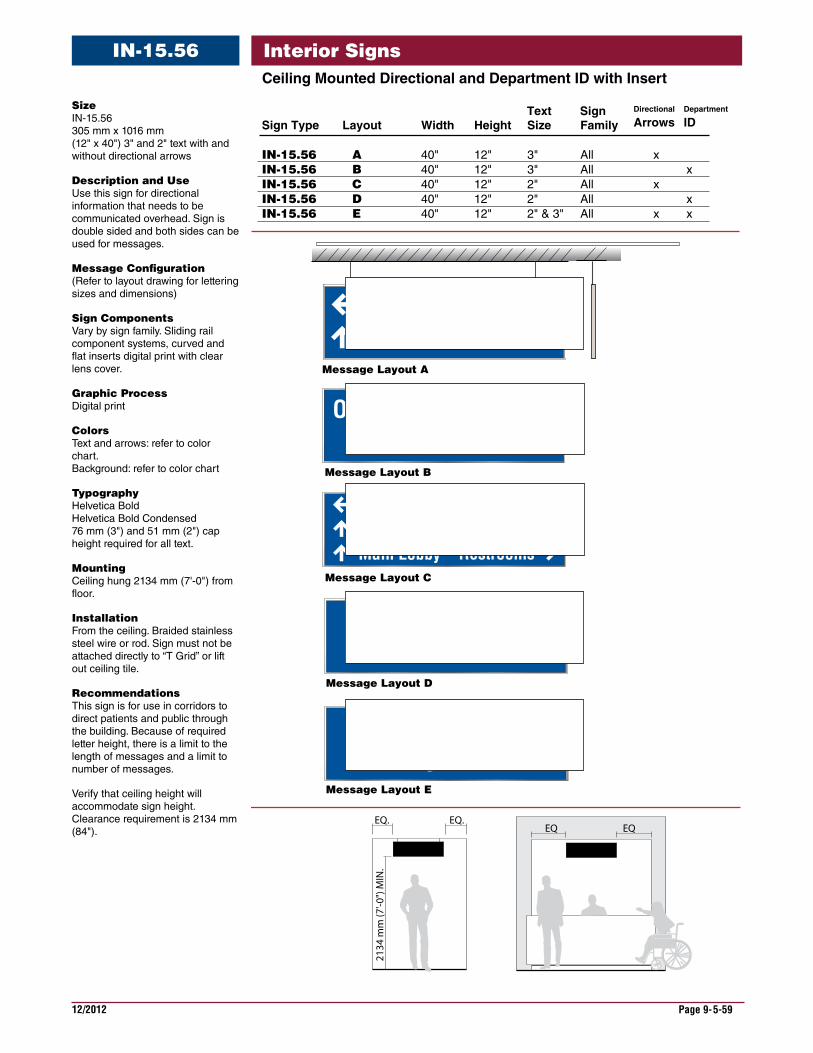
12/2012 Page 9-5-59
Interior SignsIN-15.56CeilingMountedDirectionalandDepartmentIDwithInsert
Size IN-15.56 305 mm x 1016 mm (12" x 40") 3" and 2" text with and without directional arrows
DescriptionandUse Use this sign for directional information that needs to be communicated overhead. Sign is double sided and both sides can be used for messages.
MessageConfiguration (Refer to layout drawing for lettering sizes and dimensions)
SignComponents Vary by sign family. Sliding rail component systems, curved and flat inserts digital print with clear lens cover.
GraphicProcess Digital print
Colors Text and arrows: refer to color chart. Background: refer to color chart
Typography Helvetica Bold Helvetica Bold Condensed 76 mm (3") and 51 mm (2") cap height required for all text.
Mounting Ceiling hung 2134 mm (7'-0") from floor.
Installation From the ceiling. Braided stainless steel wire or rod. Sign must not be attached directly to “T Grid” or lift out ceiling tile.
Recommendations This sign is for use in corridors to direct patients and public through the building. Because of required letter height, there is a limit to the length of messages and a limit to number of messages.
Verify that ceiling height will accommodate sign height. Clearance requirement is 2134 mm (84").
Message Layout D
Message Layout E
EQ. EQ.
2134
mm
(7'-0
") M
IN.
Message Layout A
EQ EQ
Outpatient Receptionist& Registration
Outpatient ServicesElevatorsMain Lobby
Outpatient Receptionist& Registration
Restrooms
VendingCanteen
Message Layout B
Message Layout C
Outpatient Receptionist
& Registration
Sign Type Layout Width Height Size Family
IN-15.56 A 40" 12" 3" All xIN-15.56 B 40" 12" 3" All xIN-15.56 C 40" 12" 2" All x IN-15.56 D 40" 12" 2" All xIN-15.56 E 40" 12" 2" & 3" All x x
Text Sign Department
IDDirectional
Arrows
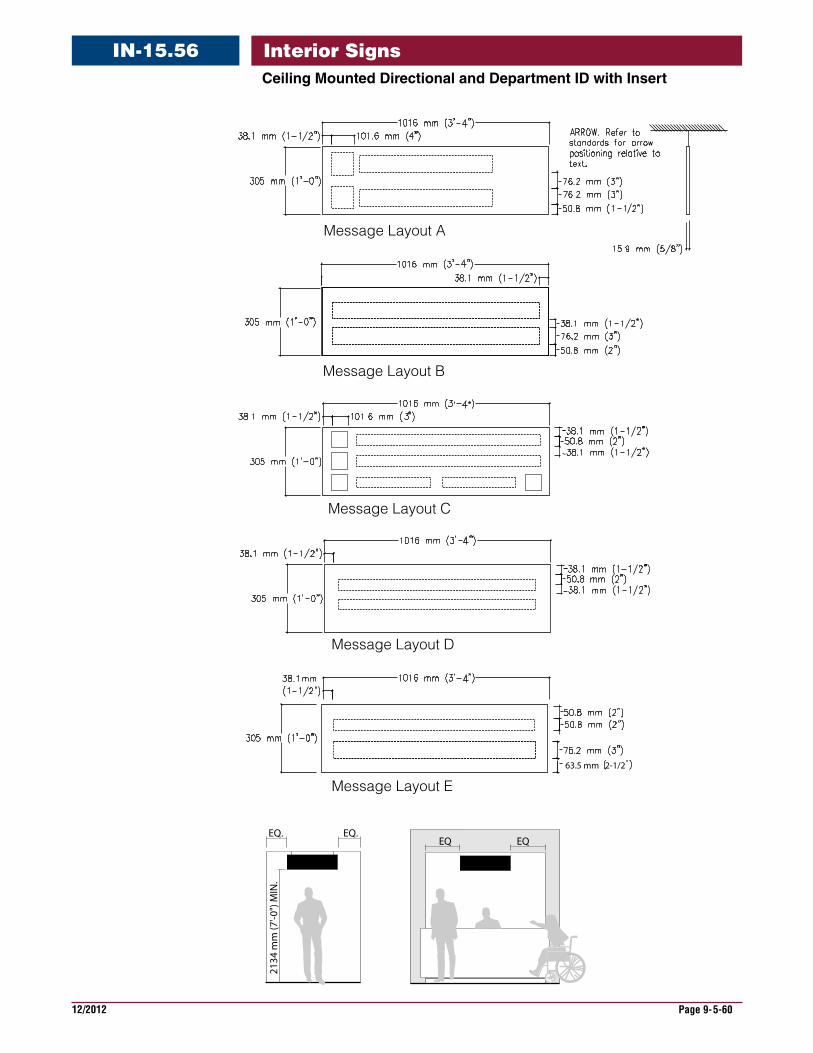
12/2012 Page 9-5-60
Interior SignsIN-15.56CeilingMountedDirectionalandDepartmentIDwithInsert
Message Layout B
Message Layout A
Message Layout C
Message Layout D
63.5 mm 2-1/2
Message Layout E
EQ. EQ.
2134
mm
(7'-0
") M
IN.
EQ EQ
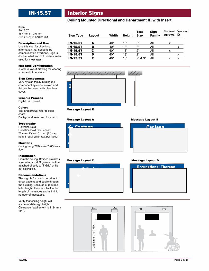
12/2012 Page 9-5-61
Interior SignsIN-15.57CeilingMountedDirectionalandDepartmentIDwithInsert
Size IN-15.57 457 mm x 1016 mm (18" x 40") 3" and 2" text
DescriptionandUse Use this sign for directional information that needs to be communicated overhead. Sign is double sided and both sides can be used for messages.
MessageConfiguration (Refer to layout drawing for lettering sizes and dimensions)
SignComponents Vary by sign family. Sliding rail component systems, curved and flat graphic insert with clear lens cover.
GraphicProcess Digital print insert.
Colors Text and arrows: refer to color chart. Background: refer to color chart
Typography Helvetica Bold Helvetica Bold Condensed 76 mm (3") and 51 mm (2") cap height required for text per layout
Mounting Ceiling hung 2134 mm (7'-0") from floor.
Installation From the ceiling. Braided stainless steel wire or rod. Sign must not be attached directly to “T Grid” or lift out ceiling tile.
Recommendations This sign is for use in corridors to direct patients and public through the building. Because of required letter height, there is a limit to the length of messages and a limit to number of messages.
Verify that ceiling height will accommodate sign height. Clearance requirement is 2134 mm (84").
EQ. EQ.
2134
mm
(7'-0
") M
IN.
EQ EQ
Outpatient Receptionist& Registration
Check-In
Retail StoreATM & Vending
Canteen Canteen Retail Store
ATM & Vending
Pick-up Order
Canteen Deli Take-Out
Occupational Therapy Conference Center
Blood Draw Medical Records
Message Layout E
Message Layout A Message Layout B
Message Layout C Message Layout D
Sign Type Layout Width Height Size Family
IN-15.57 A 40" 18" 3" All xIN-15.57 B 40" 18" 3" All xIN-15.57 C 40" 18" 2" All x IN-15.57 D 40" 18" 2" All xIN-15.57 E 40" 18" 2" & 3" All x x
Text Sign Department
IDDirectional
Arrows
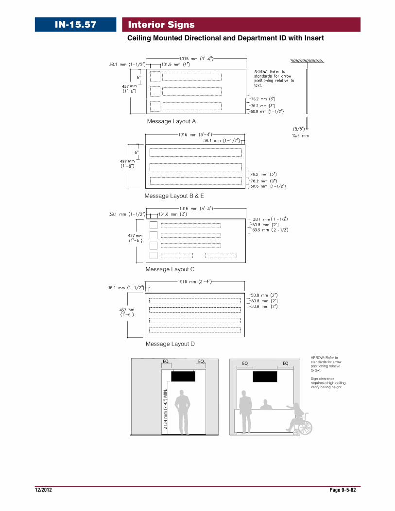
12/2012 Page 9-5-62
Interior SignsIN-15.57CeilingMountedDirectionalandDepartmentIDwithInsert
Message Layout C
Message Layout D
Message Layout B & E
Message Layout A
457
6"
457
6"
457
457
2 - 1/2
1 - 1/2
63.5
EQ. EQ.
2134
mm
(7'-0
") M
IN.
EQ EQARROW: Refer tostandards for arrowpositioning relativeto text.
Sign clearance requires a high ceiling.Verify ceiling height.

12/2012 Page 9-5-63
Interior SignsIN-15.61CeilingMountedDirectionalandDepartmentID
Message Layout A
Canteen Pharmacy
Message Layout C
Financial ManagmentCLC Dining Hall
Occupational TherapyImaging Center - Radiology
Message Layout B
Ear, Nose & Throat Clinic
2134
mm
(7'-0
") M
IN.
EQ. EQ.
Message Layout D
Imaging ServicesWaiting Area 1 Waiting Area 2
Sign Type Layout Width Height Size Family
IN-15.61 A 80" 6" 3" All xIN-15.61 B 80" 6" 3" All xIN-15.61 C 80" 6" 2" All x IN-15.61 D 80" 6" 3" & 2" All x
Text Sign Department
IDDirectional
Arrows
Size IN-15.61 152 mm x 2032 mm (6" x 80") 3" and 2" text with and without directional arrows
DescriptionandUse Use this sign for directional information that needs to be communicated overhead. Sign is double sided and both sides can be used for messages.
MessageConfiguration (Refer to layout drawing for lettering sizes and dimensions)
SignComponents Vary by sign family. Sliding rail component systems, curved and flat panel with vinyl applied graphics.
GraphicProcess Surface applied vinyl.
Colors Text and arrows: refer to color chart. Background: refer to color chart
Typography Helvetica Bold Helvetica Bold Condensed 76 mm (3") and 51 mm (2") cap height required for all text.
Mounting Ceiling hung 2134 mm (7'-0") from floor.
Installation From the ceiling. Braided stainless steel wire or rod. Sign must not be attached directly to “T Grid” or lift out ceiling tile.
Recommendations This sign is for use in corridors to direct patients and public through the building. Because of required letter height, there is a limit to the length of messages and a limit to number of messages.
Verify that ceiling height will accommodate sign height. Clearance requirement is 2134 mm (84").
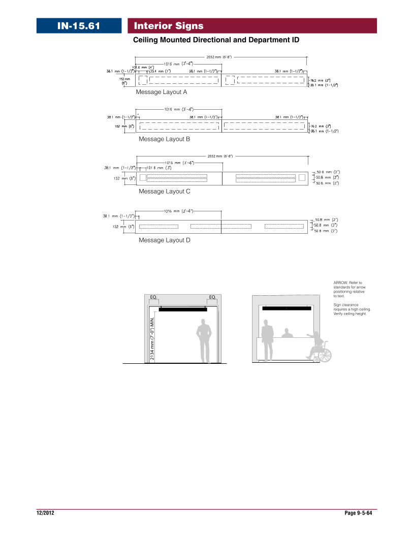
12/2012 Page 9-5-64
Interior SignsIN-15.61CeilingMountedDirectionalandDepartmentID
Message Layout A
Message Layout B
Message Layout C
Message Layout D
2032 mm (6’-8”)21
34 m
m (7
'-0")
MIN
.
EQ. EQ.
ARROW: Refer tostandards for arrowpositioning relativeto text.
Sign clearance requires a high ceiling.Verify ceiling height.
2032 mm (6’-8”)
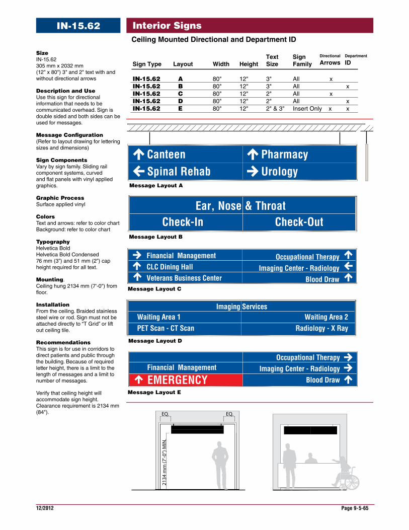
12/2012 Page 9-5-65
Interior SignsCeilingMountedDirectionalandDepartmentID
IN-15.62
Financial Management
2134
mm
(7'-0
") M
IN.
EQ. EQ.
Sign Type Layout Width Height Size Family
IN-15.62 A 80" 12" 3" All xIN-15.62 B 80" 12" 3" All xIN-15.62 C 80" 12" 2" All x IN-15.62 D 80" 12" 2" All xIN-15.62 E 80" 12" 2" & 3" Insert Only x x
Text Sign Department
IDDirectional
Arrows
Message Layout A
Spinal RehabCanteen
UrologyPharmacy
Financial ManagementCLC Dining HallVeterans Business Center
Occupational TherapyImaging Center - Radiology
Blood Draw
Check-OutCheck-InEar, Nose & Throat
Occupational TherapyImaging Center - Radiology
Blood Draw
Imaging Services
EMERGENCY
Waiting Area 1PET Scan - CT Scan
Waiting Area 2Radiology - X Ray
Message Layout B
Message Layout C
Message Layout D
Message Layout E
Size IN-15.62 305 mm x 2032 mm (12" x 80") 3" and 2" text with and without directional arrows
DescriptionandUseUse this sign for directional information that needs to be communicated overhead. Sign is double sided and both sides can be used for messages.
MessageConfiguration(Refer to layout drawing for lettering sizes and dimensions)
SignComponentsVary by sign family. Sliding rail component systems, curved and flat panels with vinyl applied graphics.
GraphicProcessSurface applied vinyl
ColorsText and arrows: refer to color chart Background: refer to color chart
Typography Helvetica Bold Helvetica Bold Condensed 76 mm (3”) and 51 mm (2”) cap height required for all text.
Mounting. Ceiling hung 2134 mm (7'-0") from floor.
Installation From the ceiling. Braided stainless steel wire or rod. Sign must not be attached directly to “T Grid” or lift out ceiling tile.
Recommendations This sign is for use in corridors to direct patients and public through the building. Because of required letter height, there is a limit to the length of messages and a limit to number of messages.
Verify that ceiling height will accommodate sign height. Clearance requirement is 2134 mm (84").
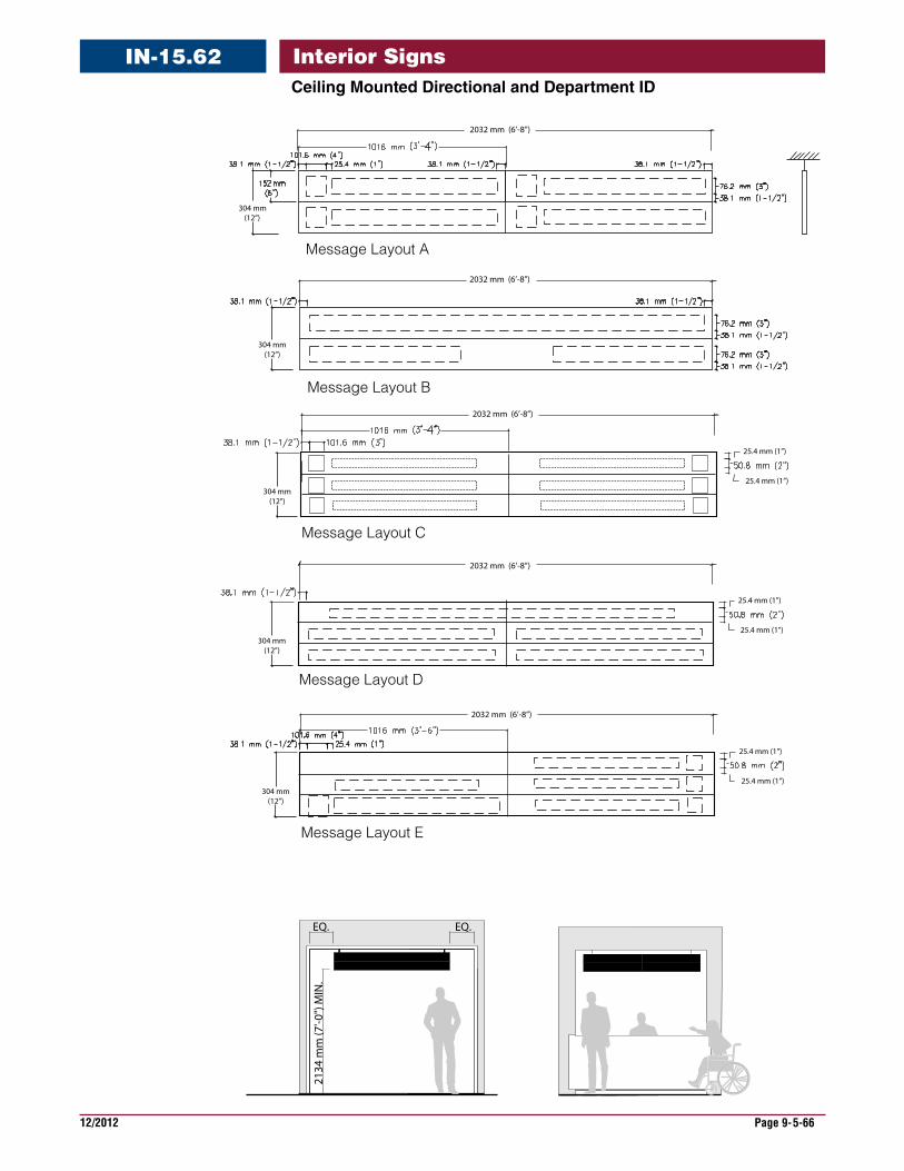
12/2012 Page 9-5-66
Interior SignsCeilingMountedDirectionalandDepartmentID
IN-15.62
Message Layout B
Message Layout C
Message Layout A
304 mm (12”)
304 mm (12”)
Message Layout D
304 mm (12”)
304 mm (12”)
Message Layout E
2032 mm (6’-8”)
304 mm (12”)
2032 mm (6’-8”)
2032 mm (6’-8”)
2032 mm (6’-8”)
2032 mm (6’-8”)
25.4 mm (1”)
25.4 mm (1”)
25.4 mm (1”)
25.4 mm (1”)
25.4 mm (1”)
25.4 mm (1”)
2134
mm
(7'-0
") M
IN.
EQ. EQ.
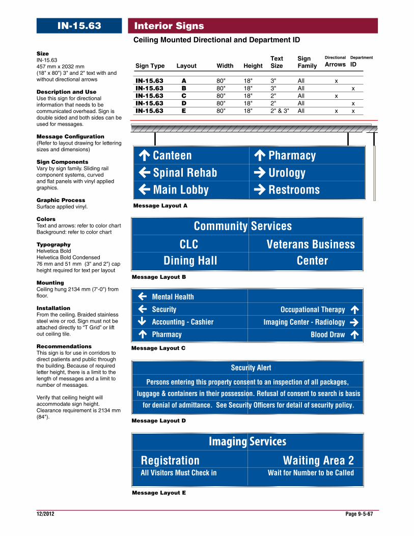
12/2012 Page 9-5-67
Interior SignsIN-15.63CeilingMountedDirectionalandDepartmentID
Message Layout A
Spinal RehabCanteen
UrologyPharmacy
Occupational Therapy
Imaging Center - Radiology
Blood Draw
Veterans Business Center
CLC Dining Hall
Community Services
Security Alert
Persons entering this property consent to an inspection of all packages,
luggage & containers in their possession. Refusal of consent to search is basis
for denial of admittance. See Security Of�cers for detail of security policy.
Main Lobby Restrooms
Mental Health
Security
Accounting - Cashier
Pharmacy
Imaging ServicesRegistrationAll Visitors Must Check in
Waiting Area 2Wait for Number to be Called
Message Layout B
Message Layout C
Message Layout D
Message Layout E
Sign Type Layout Width Height Size Family
IN-15.63 A 80" 18" 3" All xIN-15.63 B 80" 18" 3" All xIN-15.63 C 80" 18" 2" All x IN-15.63 D 80" 18" 2" All xIN-15.63 E 80" 18" 2" & 3" All x x
Text Sign Department
IDDirectional
Arrows
Size IN-15.63 457 mm x 2032 mm (18" x 80") 3" and 2" text with and without directional arrows
DescriptionandUse Use this sign for directional information that needs to be communicated overhead. Sign is double sided and both sides can be used for messages.
MessageConfiguration (Refer to layout drawing for lettering sizes and dimensions)
SignComponents Vary by sign family. Sliding rail component systems, curved and flat panels with vinyl applied graphics.
GraphicProcess Surface applied vinyl.
Colors Text and arrows: refer to color chart Background: refer to color chart
Typography Helvetica Bold Helvetica Bold Condensed 76 mm and 51 mm (3" and 2") cap height required for text per layout
Mounting Ceiling hung 2134 mm (7'-0") from floor.
Installation From the ceiling. Braided stainless steel wire or rod. Sign must not be attached directly to “T Grid” or lift out ceiling tile.
Recommendations This sign is for use in corridors to direct patients and public through the building. Because of required letter height, there is a limit to the length of messages and a limit to number of messages.
Verify that ceiling height will accommodate sign height. Clearance requirement is 2134 mm (84").

12/2012 Page 9-5-68
Interior SignsIN-15.63CeilingMountedDirectionalandDepartmentID
Message Layout C
Message Layout D
Message Layout B
Message Layout A
457
6"
457
457
1 - 1/4
457
2134
mm
(7'-0
") M
IN.
EQ. EQ.
CL
Verify ceiling heightfor sign clearance
2134 mm (6’-8")
Message Layout E
2032 mm (6’-8”)
2032 mm (6’-8”)
2032 mm (6’-8”)
2032 mm (6’-8”)
CL
CL
1 - 1/4
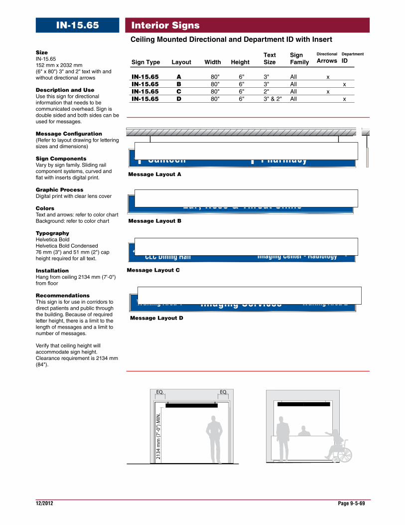
12/2012 Page 9-5-69
Interior SignsIN-15.65CeilingMountedDirectionalandDepartmentIDwithInsert
Message Layout A
Canteen Pharmacy
Financial ManagementCLC Dining Hall
Occupational TherapyImaging Center - Radiology
Ear, Nose & Throat Clinic
2134
mm
(7'-0
") M
IN.
EQ. EQ.
Imaging ServicesWaiting Area 1 Waiting Area 2
Message Layout B
Message Layout C
Message Layout D
Sign Type Layout Width Height Size Family
IN-15.65 A 80" 6" 3" All xIN-15.65 B 80" 6" 3" All xIN-15.65 C 80" 6" 2" All x IN-15.65 D 80" 6" 3" & 2" All x
Text Sign Department
IDDirectional
ArrowsSize IN-15.65 152 mm x 2032 mm (6" x 80") 3" and 2" text with and without directional arrows
DescriptionandUse Use this sign for directional information that needs to be communicated overhead. Sign is double sided and both sides can be used for messages.
MessageConfiguration (Refer to layout drawing for lettering sizes and dimensions)
SignComponents Vary by sign family. Sliding rail component systems, curved and flat with inserts digital print.
GraphicProcess Digital print with clear lens cover
Colors Text and arrows: refer to color chart Background: refer to color chart
Typography Helvetica Bold Helvetica Bold Condensed 76 mm (3") and 51 mm (2") cap height required for all text.
Installation Hang from ceiling 2134 mm (7'-0") from floor
Recommendations This sign is for use in corridors to direct patients and public through the building. Because of required letter height, there is a limit to the length of messages and a limit to number of messages.
Verify that ceiling height will accommodate sign height. Clearance requirement is 2134 mm (84").
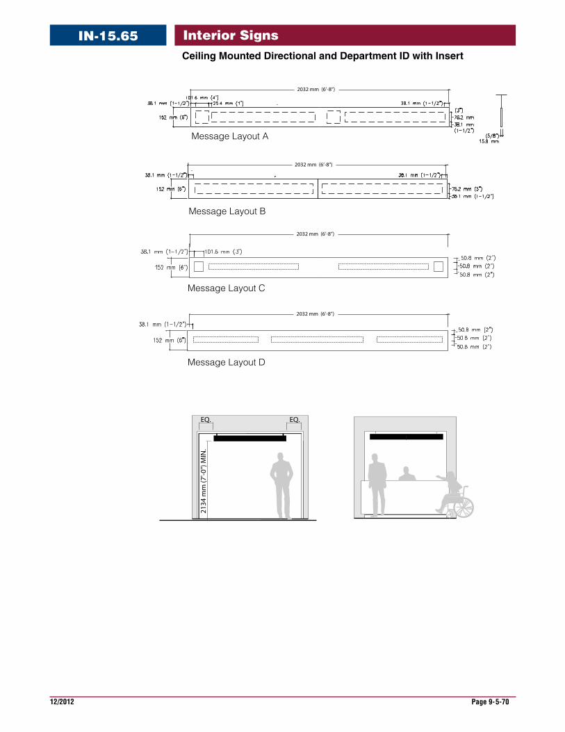
12/2012 Page 9-5-70
Interior SignsIN-15.65CeilingMountedDirectionalandDepartmentIDwithInsert
Message Layout A
Message Layout B
Message Layout C
Message Layout D
2032 mm (6’-8”)
2032 mm (6’-8”)
2032 mm (6’-8”)
2032 mm (6’-8”)
2134
mm
(7'-0
") M
IN.
EQ. EQ.
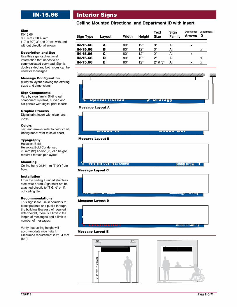
12/2012 Page 9-5-71
Interior SignsIN-15.66CeilingMountedDirectionalandDepartmentIDwithInsert
Size IN-15.66 305 mm x 2032 mm (12" x 80") 3" and 2" text with and without directional arrows
DescriptionandUse Use this sign for directional information that needs to be communicated overhead. Sign is double sided and both sides can be used for messages.
MessageConfiguration (Refer to layout drawing for lettering sizes and dimensions)
SignComponents Vary by sign family. Sliding rail component systems, curved and flat panels with digital print inserts.
GraphicProcess Digital print insert with clear lens cover.
Colors Text and arrows: refer to color chart Background: refer to color chart
Typography Helvetica Bold Helvetica Bold Condensed 76 mm (3") and/or (2") cap height required for text per layout.
Mounting Ceiling hung 2134 mm (7'-0") from floor.
Installation From the ceiling. Braided stainless steel wire or rod. Sign must not be attached directly to “T Grid” or lift out ceiling tile.
Recommendations This sign is for use in corridors to direct patients and public through the building. Because of required letter height, there is a limit to the length of messages and a limit to number of messages.
Verify that ceiling height will accommodate sign height. Clearance requirement is 2134 mm (84").
Message Layout A
Spinal RehabCanteen
UrologyPharmacy
Financial ManagementCLC Dining HallVeterans Business Center
Occupational TherapyImaging Center - Radiology
Blood Draw
Check-OutCheck-InEar, Nose & Throat
2134
mm
(7'-0
") M
IN.
EQ. EQ.
Financial ManagementOccupational Therapy
Imaging Center - RadiologyBlood Draw
Imaging Services
EMERGENCY
Waiting Area 1PET Scan - CT Scan
Waiting Area 2Radiology - X Ray
Message Layout B
Message Layout C
Message Layout D
Message Layout E
Sign Type Layout Width Height Size Family
IN-15.66 A 80" 12" 3" All xIN-15.66 B 80" 12" 3" All xIN-15.66 C 80" 12" 2" All x IN-15.66 D 80" 12" 2" All xIN-15.66 E 80" 12" 2" & 3" All x x
Text Sign Department
IDDirectional
Arrows
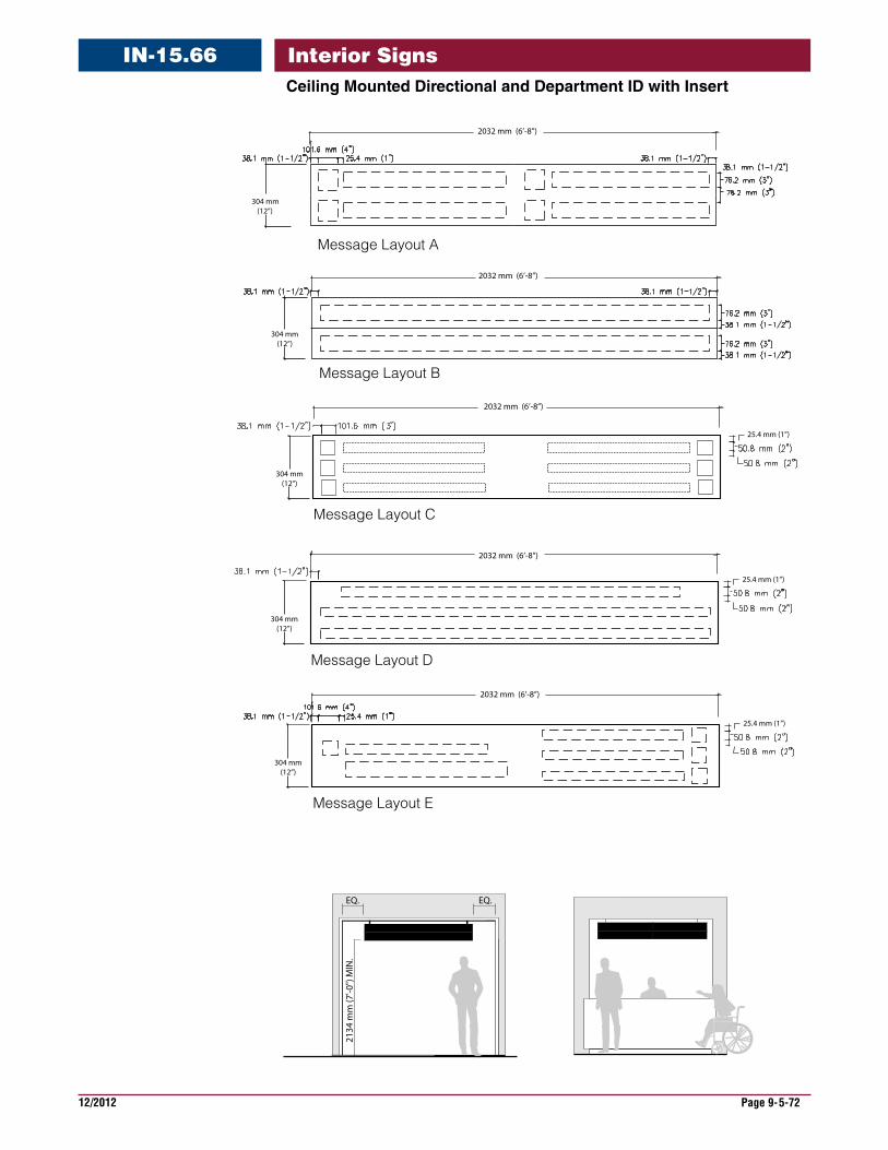
12/2012 Page 9-5-72
Interior SignsIN-15.66CeilingMountedDirectionalandDepartmentIDwithInsert
Message Layout B
Message Layout C
Message Layout A
304 mm (12”)
304 mm (12”)
Message Layout D
304 mm (12”)
304 mm (12”)
Message Layout E
2032 mm (6’-8”)
304 mm (12”)
2032 mm (6’-8”)
2032 mm (6’-8”)
2032 mm (6’-8”)
2032 mm (6’-8”)
25.4 mm (1”)
25.4 mm (1”)
25.4 mm (1”)
2134
mm
(7'-0
") M
IN.
EQ. EQ.
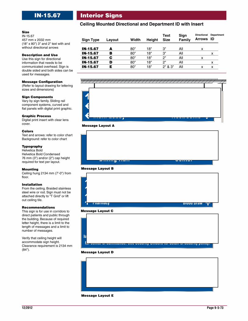
12/2012 Page 9-5-73
Interior SignsIN-15.67CeilingMountedDirectionalandDepartmentIDwithInsert
Message Layout A
Spinal RehabCanteen
UrologyPharmacy
Occupational Therapy
Imaging Center - Radiology
Blood Draw
Veterans Business Center
Community Living Dining Hall
Community Services
Security Alert
Persons entering this property consent to an inspection of all packages, luggage & container in their possession. Refusal of consent to search is basis for denial of admittance. See Security Of�cers for detail of security policy.
Main Lobby Restrooms
Mental Health
Security
Accounting - Cashier
Pharmacy
Imaging ServicesRegistrationAll Visitor Must Check in
Waiting Area 2Wait for Number to be Called
Message Layout B
Message Layout C
Message Layout D
Message Layout E
Sign Type Layout Width Height Size Family
IN-15.67 A 80" 18" 3" All xIN-15.67 B 80" 18" 3" All xIN-15.67 C 80" 18" 2" All x IN-15.67 D 80" 18" 2" All xIN-15.67 E 80" 18" 2" & 3" All x x
Text Sign Department
IDDirectional
Arrows
Size IN-15.67 457 mm x 2032 mm (18" x 80") 3" and 2" text with and without directional arrows
DescriptionandUse Use this sign for directional information that needs to be communicated overhead. Sign is double sided and both sides can be used for messages.
MessageConfiguration (Refer to layout drawing for lettering sizes and dimensions)
SignComponents Vary by sign family. Sliding rail component systems, curved and flat panels with digital print graphic.
GraphicProcess Digital print insert with clear lens cover.
Colors Text and arrows: refer to color chart Background: refer to color chart
Typography Helvetica Bold Helvetica Bold Condensed 76 mm (3") and/or (2") cap height required for text per layout.
Mounting Ceiling hung 2134 mm (7'-0") from floor.
Installation From the ceiling. Braided stainless steel wire or rod. Sign must not be attached directly to “T Grid” or lift out ceiling tile.
Recommendations This sign is for use in corridors to direct patients and public through the building. Because of required letter height, there is a limit to the length of messages and a limit to number of messages.
Verify that ceiling height will accommodate sign height. Clearance requirement is 2134 mm (84").

12/2012 Page 9-5-74
Interior SignsIN-15.67CeilingMountedDirectionalandDepartmentIDwithInsert
Message Layout C
Message Layout D
Message Layout B
Message Layout A
457
457
457
457
2134
mm
(7'-0
") M
IN.
EQ. EQ.
Verify ceiling heightfor sign clearance
1 - 1/2
2134 mm (6’-8")
Message Layout E
2032 mm (6’-8”)
2032 mm (6’-8”)
2032 mm (6’-8”)
2032 mm (6’-8”)
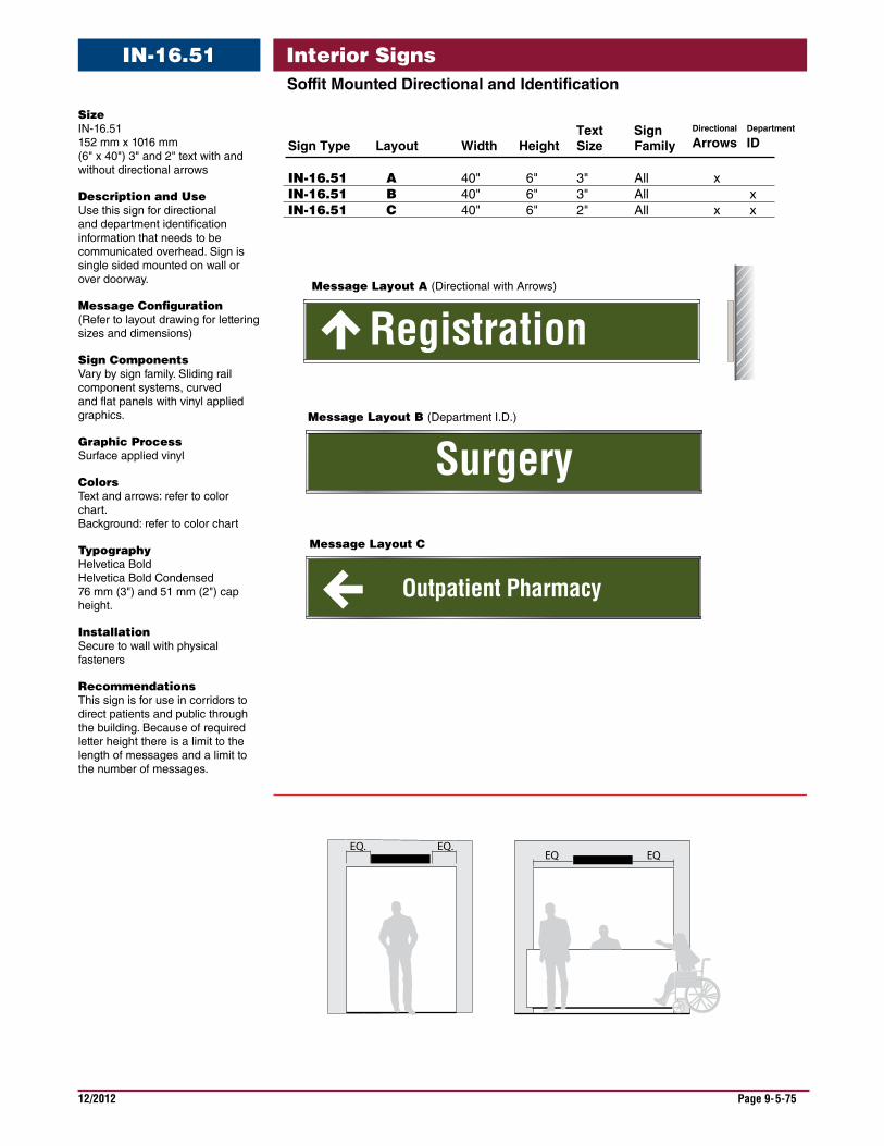
12/2012 Page 9-5-75
Interior SignsSoffitMountedDirectionalandIdentification
IN-16.51
Registration
EQ. EQ.EQ EQ
Outpatient Pharmacy
Surgery
Sign Type Layout Width Height Size Family
IN-16.51 A 40" 6" 3" All xIN-16.51 B 40" 6" 3" All xIN-16.51 C 40" 6" 2" All x x
Text Sign Department
IDDirectional
Arrows
Message Layout B (Department I.D.)
Message Layout A (Directional with Arrows)
Message Layout C
Size IN-16.51 152 mm x 1016 mm (6" x 40") 3" and 2" text with and without directional arrows
DescriptionandUse Use this sign for directional and department identification information that needs to be communicated overhead. Sign is single sided mounted on wall or over doorway.
MessageConfiguration (Refer to layout drawing for lettering sizes and dimensions)
SignComponents Vary by sign family. Sliding rail component systems, curved and flat panels with vinyl applied graphics.
GraphicProcess Surface applied vinyl
Colors Text and arrows: refer to color chart. Background: refer to color chart
Typography Helvetica Bold Helvetica Bold Condensed 76 mm (3") and 51 mm (2") cap height.
Installation Secure to wall with physical fasteners
Recommendations This sign is for use in corridors to direct patients and public through the building. Because of required letter height there is a limit to the length of messages and a limit to the number of messages.
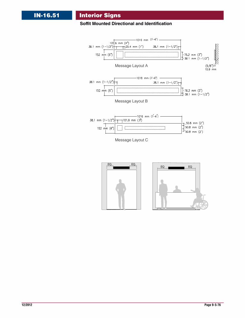
12/2012 Page 9-5-76
Interior SignsSoffitMountedDirectionalandIdentification
IN-16.51
Message Layout A
Message Layout B
Message Layout C
EQ. EQ.EQ EQ
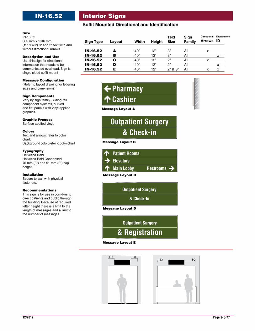
12/2012 Page 9-5-77
Interior SignsSoffitMountedDirectionalandIdentification
IN-16.52
EQ. EQ.EQ EQ
Message Layout C
Outpatient Surgery
& Registration
Message Layout D
Message Layout E
Outpatient Surgery& Check-in
Patient Rooms
Elevators
Main Lobby
Outpatient Surgery
& Check-In
Restrooms
Pharmacy Cashier
Sign Type Layout Width Height Size Family
IN-16.52 A 40" 12" 3" All xIN-16.52 B 40" 12" 3" All xIN-16.52 C 40" 12" 2" All x IN-16.52 D 40" 12" 2" All xIN-16.52 E 40" 12" 2" & 3" All x x
Text Sign Department
IDDirectional
Arrows
Message Layout B
Message Layout A
Size IN-16.52 305 mm x 1016 mm (12" x 40") 3" and 2" text with and without directional arrows
DescriptionandUse Use this sign for directional information that needs to be communicated overhead. Sign is single sided soffit mount
MessageConfiguration (Refer to layout drawing for lettering sizes and dimensions)
SignComponents Vary by sign family. Sliding rail component systems, curved and flat panels with vinyl applied graphics.
GraphicProcess Surface applied vinyl,
Colors Text and arrows: refer to color chart. Background color: refer to color chart
Typography Helvetica Bold Helvetica Bold Condensed 76 mm (3") and 51 mm (2") cap height
Installation Secure to wall with physical fasteners.
Recommendations This sign is for use in corridors to direct patients and public through the building. Because of required letter height there is a limit to the length of messages and a limit to the number of messages.
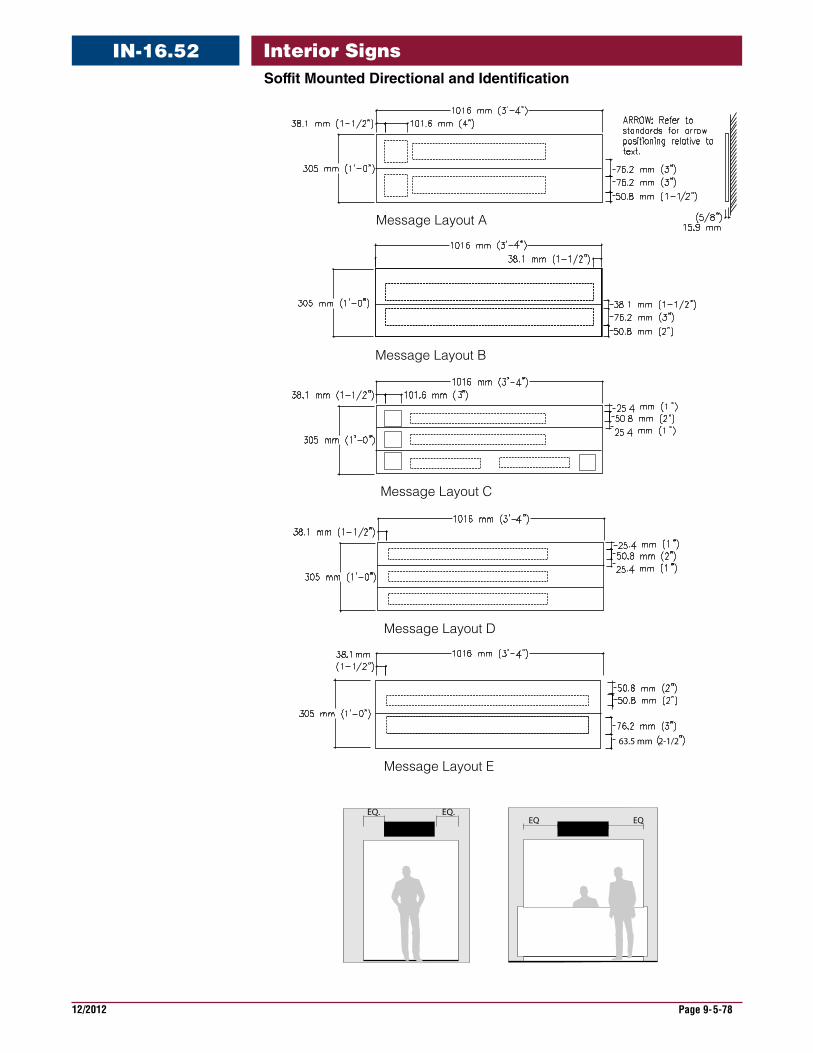
12/2012 Page 9-5-78
Interior SignsSoffitMountedDirectionalandIdentification
IN-16.52
Message Layout B
Message Layout A
Message Layout C
Message Layout D
63.5 mm 2-1/2
Message Layout E
EQ. EQ.EQ EQ
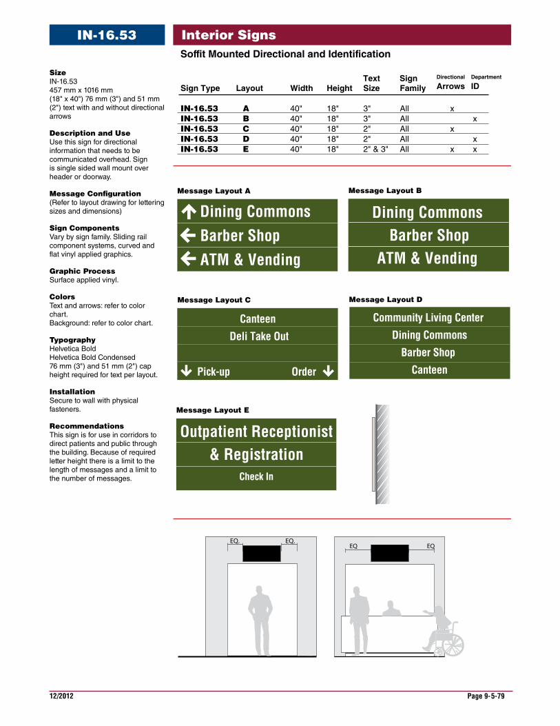
12/2012 Page 9-5-79
Interior SignsIN-16.53SoffitMountedDirectionalandIdentification
EQ. EQ.EQ EQ
Barber ShopATM & Vending
Dining Commons
Pick-up Order
Dining Commons Barber Shop
ATM & Vending
Community Living Center
Dining Commons
Barber Shop
Canteen
Outpatient Receptionist& Registration
Check In
Canteen
Deli Take Out
Sign Type Layout Width Height Size Family
IN-16.53 A 40" 18" 3" All xIN-16.53 B 40" 18" 3" All xIN-16.53 C 40" 18" 2" All x IN-16.53 D 40" 18" 2" All xIN-16.53 E 40" 18" 2" & 3" All x x
Text Sign Department
IDDirectional
Arrows
Message Layout A
Message Layout E
Message Layout C
Message Layout B
Message Layout D
Size IN-16.53 457 mm x 1016 mm (18" x 40") 76 mm (3") and 51 mm (2") text with and without directional arrows
DescriptionandUse Use this sign for directional information that needs to be communicated overhead. Sign is single sided wall mount over header or doorway.
MessageConfiguration (Refer to layout drawing for lettering sizes and dimensions)
SignComponents Vary by sign family. Sliding rail component systems, curved and flat vinyl applied graphics.
GraphicProcess Surface applied vinyl.
Colors Text and arrows: refer to color chart. Background: refer to color chart.
Typography Helvetica Bold Helvetica Bold Condensed 76 mm (3") and 51 mm (2") cap height required for text per layout.
Installation Secure to wall with physical fasteners.
Recommendations This sign is for use in corridors to direct patients and public through the building. Because of required letter height there is a limit to the length of messages and a limit to the number of messages.
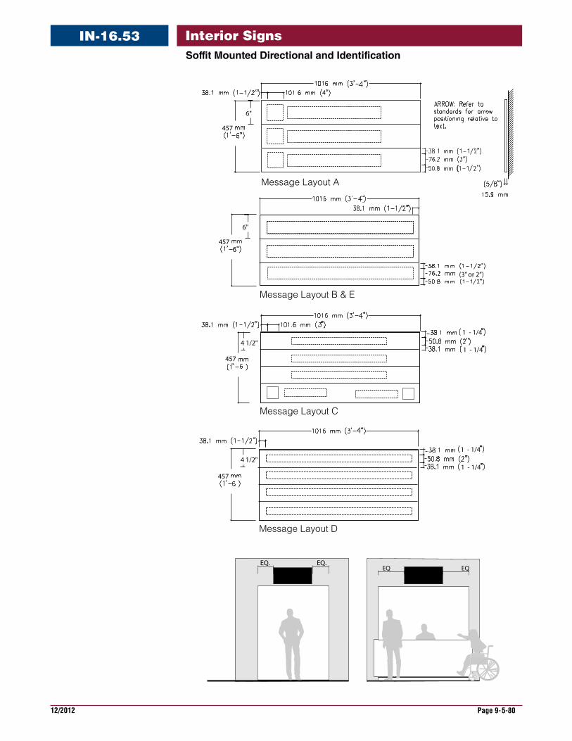
12/2012 Page 9-5-80
Interior SignsSoffitMountedDirectionalandIdentification
IN-16.53
Message Layout C
Message Layout D
Message Layout B & E
Message Layout A
457
6"
457
6"
4571 - 1/4
4571 - 1/4
1 - 1/4
(3” or 2”)
1 - 1/4
4 1/2"
4 1/2"
EQ. EQ.EQ EQ
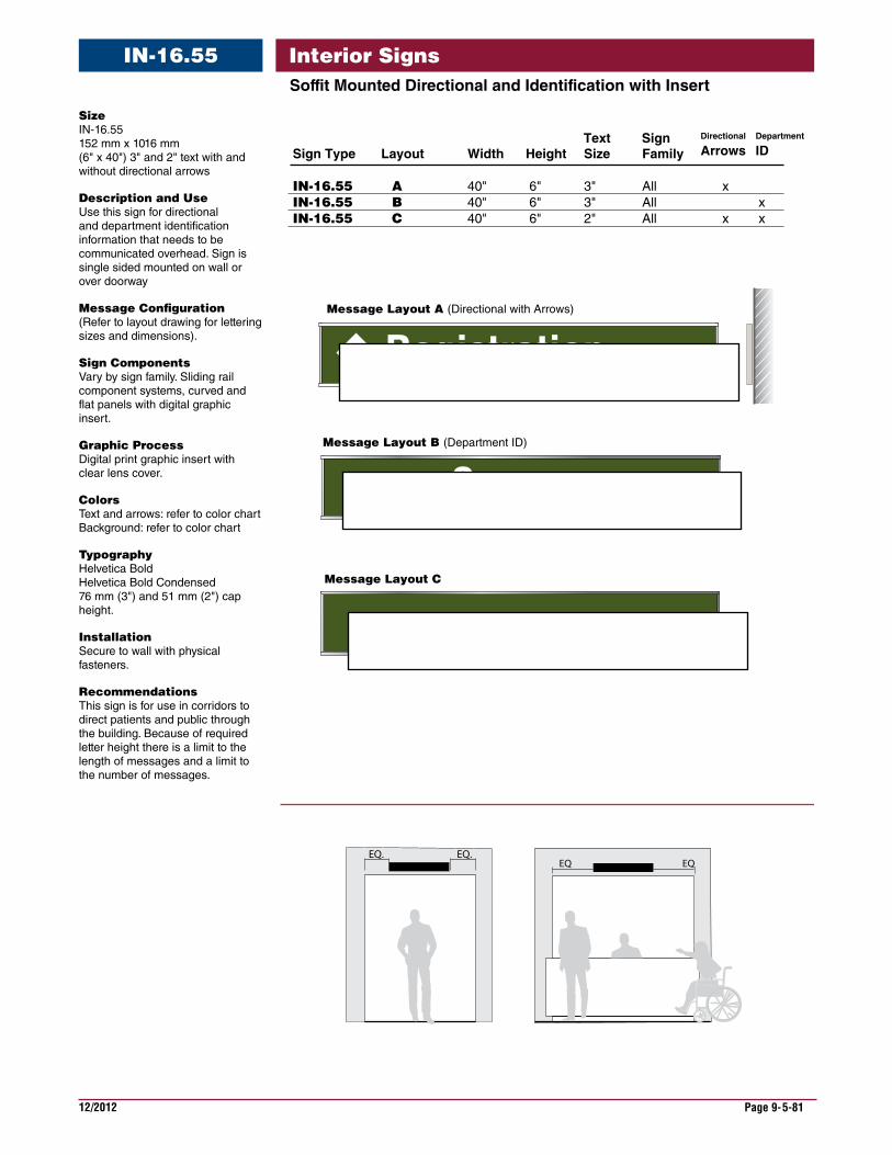
12/2012 Page 9-5-81
Interior SignsSoffitMountedDirectionalandIdentificationwithInsert
IN-16.55
Size IN-16.55 152 mm x 1016 mm (6" x 40") 3" and 2" text with and without directional arrows
DescriptionandUse Use this sign for directional and department identification information that needs to be communicated overhead. Sign is single sided mounted on wall or over doorway
MessageConfiguration (Refer to layout drawing for lettering sizes and dimensions).
SignComponents Vary by sign family. Sliding rail component systems, curved and flat panels with digital graphic insert.
GraphicProcess Digital print graphic insert with clear lens cover.
Colors Text and arrows: refer to color chart Background: refer to color chart
Typography Helvetica Bold Helvetica Bold Condensed 76 mm (3") and 51 mm (2") cap height.
Installation Secure to wall with physical fasteners.
Recommendations This sign is for use in corridors to direct patients and public through the building. Because of required letter height there is a limit to the length of messages and a limit to the number of messages.
Registration
Message Layout B (Department ID)
Message Layout A (Directional with Arrows)
EQ. EQ.EQ EQ
Message Layout C
Outpatient Pharmacy
Surgery
Sign Type Layout Width Height Size Family
IN-16.55 A 40" 6" 3" All xIN-16.55 B 40" 6" 3" All xIN-16.55 C 40" 6" 2" All x x
Text Sign Department
IDDirectional
Arrows
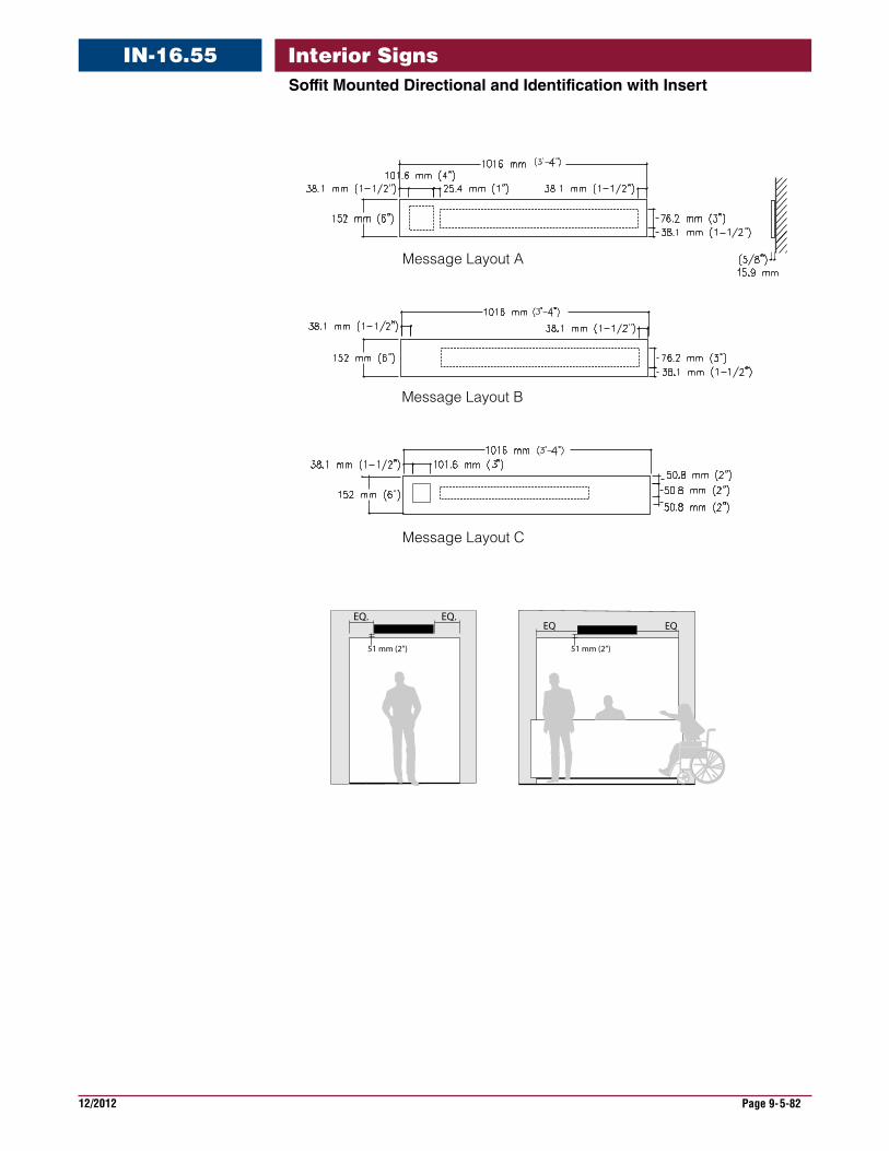
12/2012 Page 9-5-82
Interior SignsSoffitMountedDirectionalandIdentificationwithInsert
IN-16.55
Message Layout A
Message Layout B
Message Layout C
EQ. EQ.EQ EQ
51 mm (2”) 51 mm (2”)
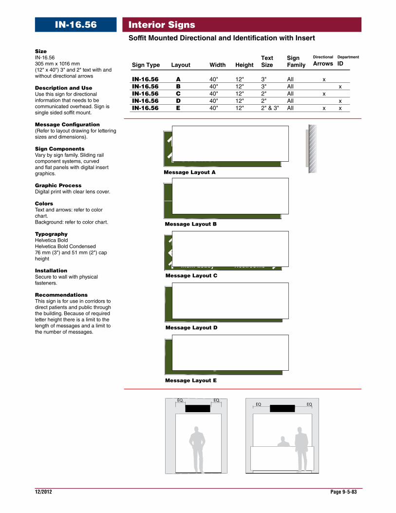
12/2012 Page 9-5-83
Interior SignsSoffitMountedDirectionalandIdentificationwithInsert
IN-16.56
Size IN-16.56 305 mm x 1016 mm (12" x 40") 3" and 2" text with and without directional arrows
DescriptionandUse Use this sign for directional information that needs to be communicated overhead. Sign is single sided soffit mount.
MessageConfiguration (Refer to layout drawing for lettering sizes and dimensions).
SignComponents Vary by sign family. Sliding rail component systems, curved and flat panels with digital insert graphics.
GraphicProcess Digital print with clear lens cover.
Colors Text and arrows: refer to color chart. Background: refer to color chart.
Typography Helvetica Bold Helvetica Bold Condensed 76 mm (3") and 51 mm (2") cap height
Installation Secure to wall with physical fasteners.
Recommendations This sign is for use in corridors to direct patients and public through the building. Because of required letter height there is a limit to the length of messages and a limit to the number of messages.
EQ. EQ.
Message Layout A
Message Layout B
EQ EQ
Message Layout C
Outpatient Surgery
& Registration
Message Layout D
Message Layout E
Outpatient Surgery& Check-in
Patient Rooms
Elevators
Main Lobby
Outpatient Surgery
& Check-In
Restrooms
Pharmacy Cashier
Sign Type Layout Width Height Size Family
IN-16.56 A 40" 12" 3" All xIN-16.56 B 40" 12" 3" All xIN-16.56 C 40" 12" 2" All x IN-16.56 D 40" 12" 2" All xIN-16.56 E 40" 12" 2" & 3" All x x
Text Sign Department
IDDirectional
Arrows
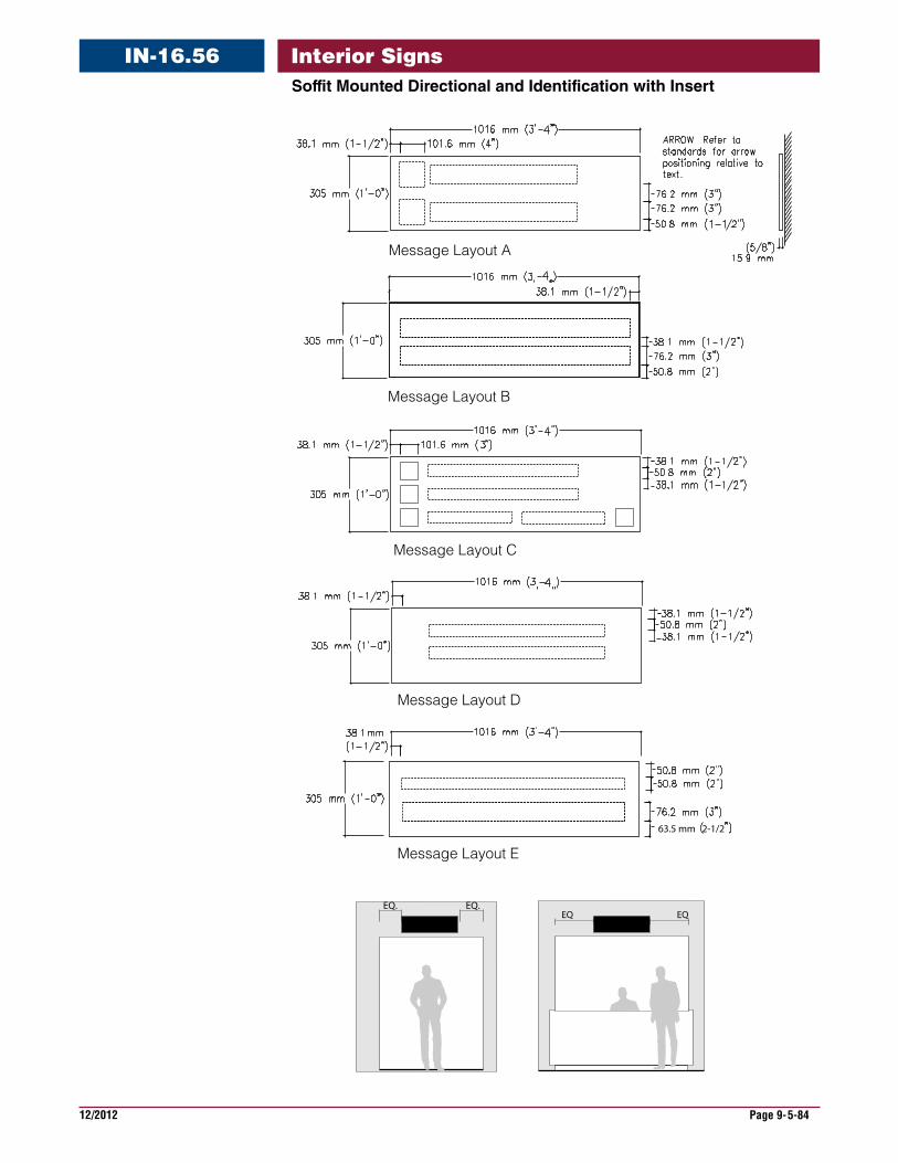
12/2012 Page 9-5-84
Interior SignsSoffitMountedDirectionalandIdentificationwithInsert
IN-16.56
Message Layout B
Message Layout A
Message Layout C
Message Layout D
63.5 mm 2-1/2
Message Layout E
EQ. EQ.EQ EQ
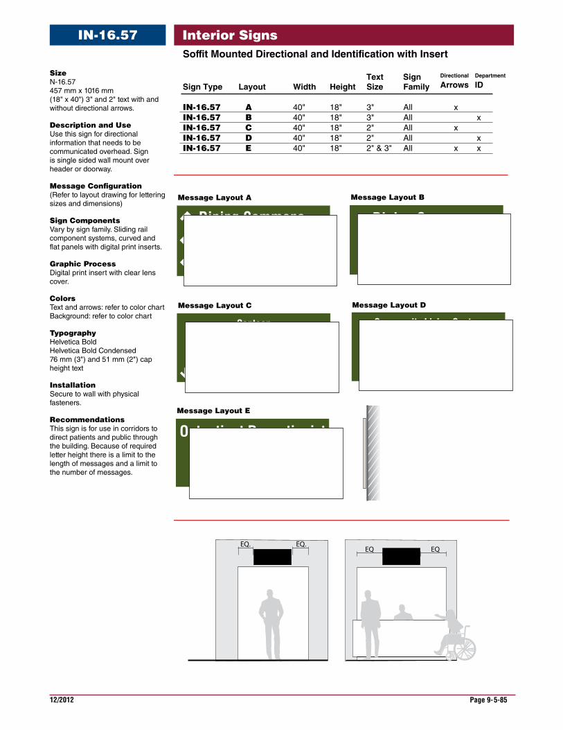
12/2012 Page 9-5-85
Interior SignsSoffitMountedDirectionalandIdentificationwithInsert
IN-16.57
Size N-16.57 457 mm x 1016 mm (18" x 40") 3" and 2" text with and without directional arrows.
DescriptionandUse Use this sign for directional information that needs to be communicated overhead. Sign is single sided wall mount over header or doorway.
MessageConfiguration (Refer to layout drawing for lettering sizes and dimensions)
SignComponents Vary by sign family. Sliding rail component systems, curved and flat panels with digital print inserts.
GraphicProcess Digital print insert with clear lens cover.
Colors Text and arrows: refer to color chart Background: refer to color chart
Typography Helvetica Bold Helvetica Bold Condensed 76 mm (3") and 51 mm (2") cap height text
Installation Secure to wall with physical fasteners.
Recommendations This sign is for use in corridors to direct patients and public through the building. Because of required letter height there is a limit to the length of messages and a limit to the number of messages.
EQ. EQ.EQ EQ
Barber ShopATM & Vending
Dining Commons
Pick-up Order
Dining Commons Barber Shop
ATM & Vending
Community Living Center
Dining Commons
Barber Shop
Canteen
Outpatient Receptionist& Registration
Check In
Canteen
Deli Take Out
Sign Type Layout Width Height Size Family
IN-16.57 A 40" 18" 3" All xIN-16.57 B 40" 18" 3" All xIN-16.57 C 40" 18" 2" All x IN-16.57 D 40" 18" 2" All xIN-16.57 E 40" 18" 2" & 3" All x x
Text Sign Department
IDDirectional
Arrows
Message Layout E
Message Layout A
Message Layout C
Message Layout B
Message Layout D
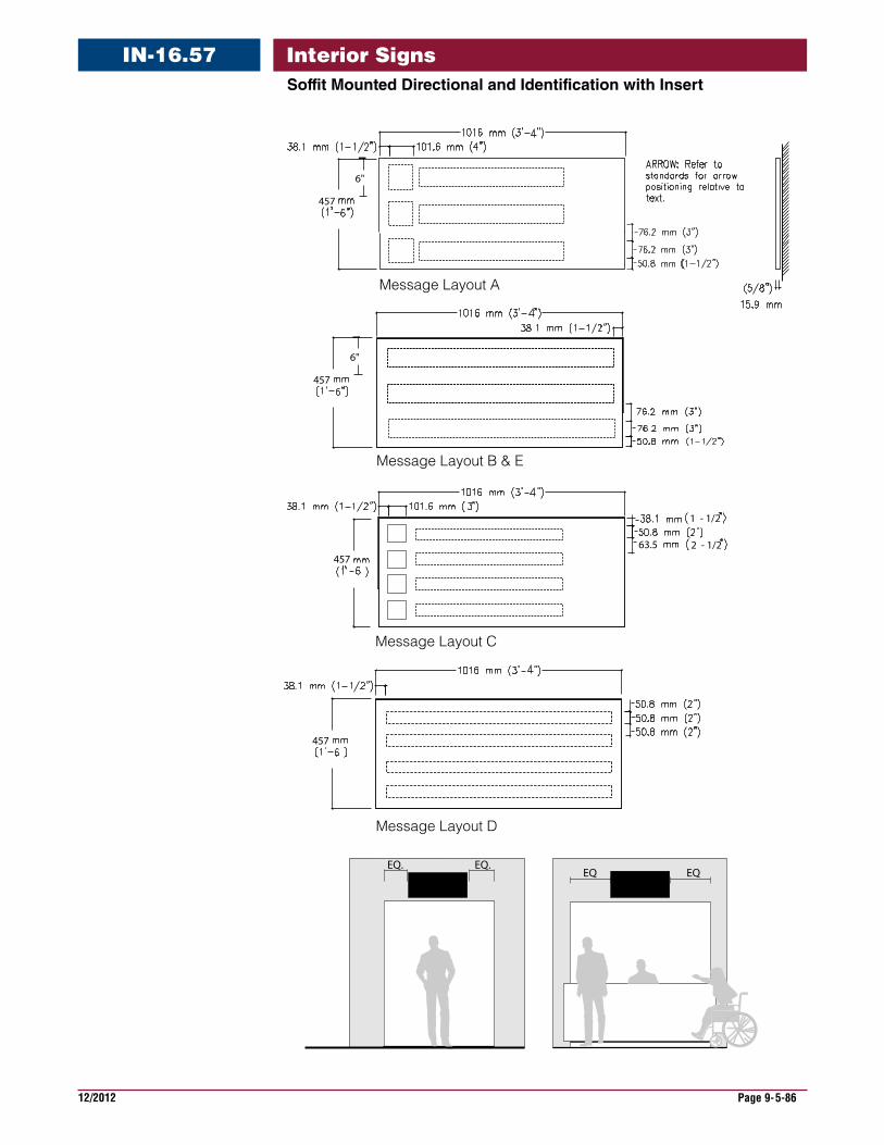
12/2012 Page 9-5-86
Interior SignsSoffitMountedDirectionalandIdentificationwithInsert
IN-16.57
Message Layout C
Message Layout D
Message Layout B & E
Message Layout A
457
6"
457
6"
4572 - 1/2
457
1 - 1/2
63.5
EQ. EQ.EQ EQ
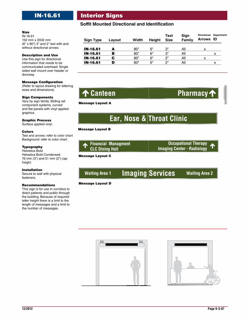
12/2012 Page 9-5-87
Interior SignsIN-16.61SoffitMountedDirectionalandIdentification
Message Layout A
Canteen Pharmacy
Financial ManagmentCLC Dining Hall
Occupational TherapyImaging Center - Radiology
Ear, Nose & Throat Clinic
EQ. EQ.
Imaging ServicesWaiting Area 1 Waiting Area 2
Message Layout B
Message Layout C
Message Layout D
Sign Type Layout Width Height Size Family
IN-16.61 A 80" 6" 3" All xIN-16.61 B 80" 6" 3" All xIN-16.61 C 80" 6" 2" All x IN-16.61 D 80" 6" 2" All x
Text Sign Department
IDDirectional
Arrows
Size IN-16.61 152 mm x 2032 mm (6" x 80") 3" and 2" text with and without directional arrows
DescriptionandUse Use this sign for directional information that needs to be communicated overhead. Single sided wall mount over header or doorway.
MessageConfiguration (Refer to layout drawing for lettering sizes and dimensions)
SignComponents Vary by sign family. Sliding rail component systems, curved and flat panels with vinyl applied graphics.
GraphicProcess Surface applied vinyl.
Colors Text and arrows: refer to color chart Background: refer to color chart
Typography Helvetica Bold Helvetica Bold Condensed 76 mm (3") and 51 mm (2") cap height.
Installation Secure to wall with physical fasteners.
Recommendations This sign is for use in corridors to direct patients and public through the building. Because of required letter height there is a limit to the length of messages and a limit to the number of messages.

12/2012 Page 9-5-88
Interior SignsIN-16.61SoffitMountedDirectionalandIdentification
Message Layout A
Message Layout B
Message Layout C
2032 mm (6’-8”)
2032 mm (6’-8”)
EQ. EQ.
Message Layout D
2032 mm (6’-8”)

12/2012 Page 9-5-89
Interior SignsSoffitMountedDirectionalandIdentification
IN-16.62
Spinal RehabCanteen
UrologyPharmacy
Financial ManagementCLC Dining HallVeteran’s Business Center
Occupational TherapyImaging Center - Radiology
Blood Draw
Check-OutCheck-InEar, Nose & Throat
EQ. EQ.
Message Layout D
Imaging Services
Waiting Area 1PET Scan - CT Scan
Waiting Area 2Radiology - X Ray
Message Layout C
Message Layout B
Message Layout A
Sign Type Layout Width Height Size Family
IN-16.62 A 80" 12" 3" All xIN-16.62 B 80" 12" 3" All xIN-16.62 C 80" 12" 2" All x IN-16.62 D 80" 12" 2" All x
Text Sign Department
IDDirectional
Arrows
Size IN-16.62 305 mm x 2032 mm (12" x 80") 3" and 2" text with and without directional arrows
DescriptionandUse Use this sign for directional information that needs to be communicated overhead. Single sided wall mount over header or doorway.
MessageConfiguration (Refer to layout drawing for lettering sizes and dimensions)
SignComponents Varies by sign family. Sliding rail component systems, curved and flat panels with vinyl applied graphics.
GraphicProcess Surface applied vinyl.
Colors Text and arrows: refer to color chart. Background: refer to color chart.
Typography Helvetica Bold Helvetica Bold Condensed 75 mm (3") and or 50.8 mm (2") cap height
Installation Secure to wall with physical fasteners.
Recommendations This sign is for use in corridors to direct patients and public through the building. Because of required letter height there is a limit to the length of messages and a limit to the number of messages.
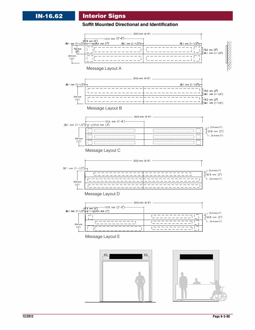
12/2012 Page 9-5-90
Interior SignsSoffitMountedDirectionalandIdentification
IN-16.62
Message Layout B
Message Layout C
Message Layout A
304 mm (12”)
304 mm (12”)
Message Layout D
304 mm (12”)
304 mm (12”)
Message Layout E
2032 mm (6’-8”)
304 mm (12”)
2032 mm (6’-8”)
2032 mm (6’-8”)
2032 mm (6’-8”)
2032 mm (6’-8”)
25.4 mm (1”)
25.4 mm (1”)
25.4 mm (1”)
25.4 mm (1”)
25.4 mm (1”)
25.4 mm (1”)
EQ. EQ.
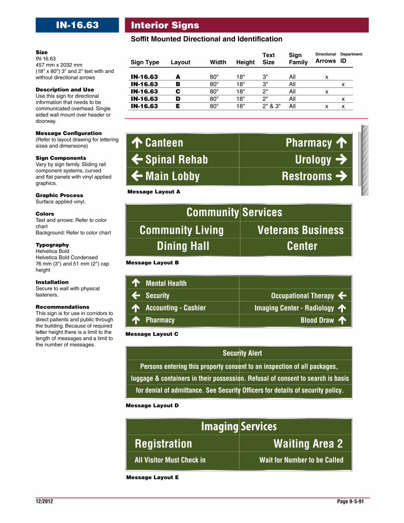
12/2012 Page 9-5-91
Interior SignsSoffitMountedDirectionalandIdentification
IN-16.63
Message Layout A
Spinal RehabCanteen
UrologyPharmacy
Occupational Therapy
Imaging Center - Radiology
Blood Draw
Veterans Business Center
Community Living Dining Hall
Community Services
Security Alert
Persons entering this property consent to an inspection of all packages,
luggage & containers in their possession. Refusal of consent to search is basis
for denial of admittance. See Security Of�cers for details of security policy.
Main Lobby Restrooms
Mental Health
Security
Accounting - Cashier
Pharmacy
Imaging ServicesRegistration Waiting Area 2
Message Layout B
Message Layout C
Message Layout D
Message Layout E
All Visitor Must Check in Wait for Number to be Called
Sign Type Layout Width Height Size Family
IN-16.63 A 80" 18" 3" All xIN-16.63 B 80" 18" 3" All xIN-16.63 C 80" 18" 2" All x IN-16.63 D 80" 18" 2" All xIN-16.63 E 80" 18" 2" & 3" All x x
Text Sign Department
IDDirectional
ArrowsSize IN-16.63 457 mm x 2032 mm (18" x 80") 3" and 2" text with and without directional arrows
DescriptionandUse Use this sign for directional information that needs to be communicated overhead. Single sided wall mount over header or doorway.
MessageConfiguration (Refer to layout drawing for lettering sizes and dimensions)
SignComponents Vary by sign family. Sliding rail component systems, curved and flat panels with vinyl applied graphics.
GraphicProcess Surface applied vinyl.
Colors Text and arrows: Refer to color chart Background: Refer to color chart
Typography Helvetica Bold Helvetica Bold Condensed 76 mm (3") and 51 mm (2") cap height
Installation Secure to wall with physical fasteners.
Recommendations This sign is for use in corridors to direct patients and public through the building. Because of required letter height there is a limit to the length of messages and a limit to the number of messages.
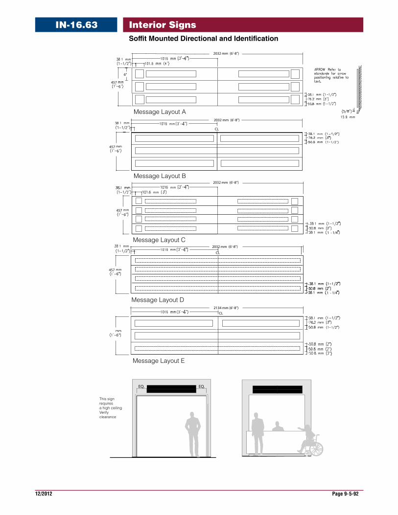
12/2012 Page 9-5-92
Interior SignsSoffitMountedDirectionalandIdentification
IN-16.63
This sign requires a high ceilingVerify clearance
Message Layout C
Message Layout D
Message Layout B
Message Layout A
457
6"
457
457
1 - 1/4
457
CL
2134 mm (6’-8")
Message Layout E
2032 mm (6’-8”)
2032 mm (6’-8”)
2032 mm (6’-8”)
2032 mm (6’-8”)
CL
CL
1 - 1/4
EQ. EQ.
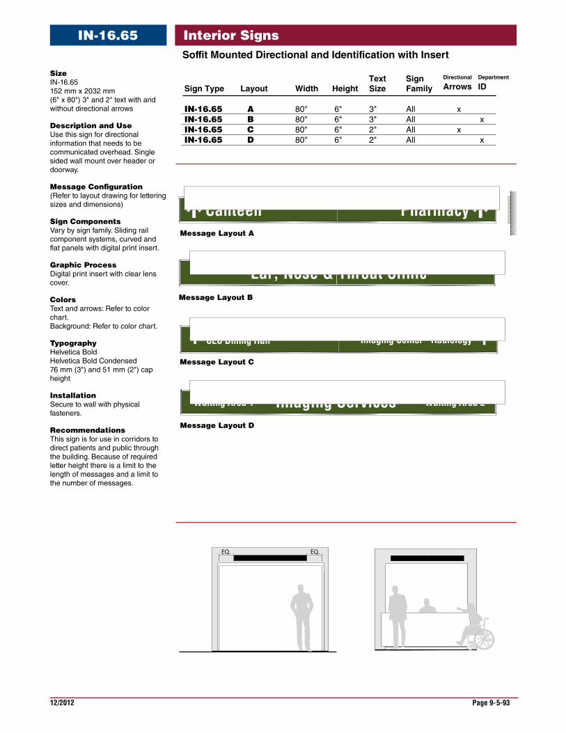
12/2012 Page 9-5-93
Interior SignsSoffitMountedDirectionalandIdentificationwithInsert
IN-16.65
Size IN-16.65 152 mm x 2032 mm (6" x 80") 3" and 2" text with and without directional arrows
DescriptionandUse Use this sign for directional information that needs to be communicated overhead. Single sided wall mount over header or doorway.
MessageConfiguration (Refer to layout drawing for lettering sizes and dimensions)
SignComponents Vary by sign family. Sliding rail component systems, curved and flat panels with digital print insert.
GraphicProcess Digital print insert with clear lens cover.
Colors Text and arrows: Refer to color chart. Background: Refer to color chart.
Typography Helvetica Bold Helvetica Bold Condensed 76 mm (3") and 51 mm (2") cap height
Installation Secure to wall with physical fasteners.
Recommendations This sign is for use in corridors to direct patients and public through the building. Because of required letter height there is a limit to the length of messages and a limit to the number of messages.
Message Layout A
Canteen Pharmacy
CLC Dining Hall Imaging Center - Radiology
Ear, Nose & Throat Clinic
EQ. EQ.
Imaging ServicesWaiting Area 1 Waiting Area 2
Message Layout B
Message Layout C
Message Layout D
Sign Type Layout Width Height Size Family
IN-16.65 A 80" 6" 3" All xIN-16.65 B 80" 6" 3" All xIN-16.65 C 80" 6" 2" All x IN-16.65 D 80" 6" 2" All x
Text Sign Department
IDDirectional
Arrows
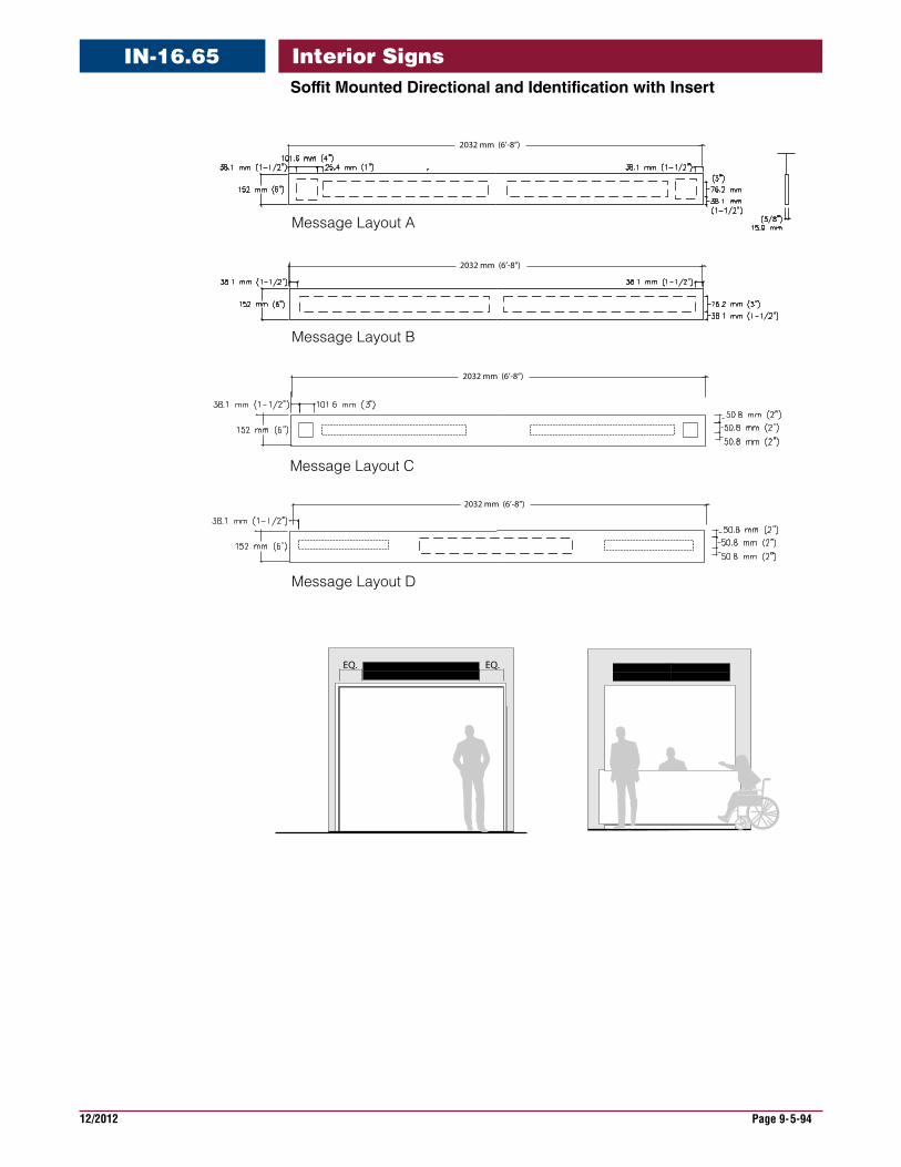
12/2012 Page 9-5-94
Interior SignsSoffitMountedDirectionalandIdentificationwithInsert
IN-16.65
Message Layout A
Message Layout B
Message Layout C
Message Layout D
2032 mm (6’-8”)
2032 mm (6’-8”)
2032 mm (6’-8”)
2032 mm (6’-8”)
EQ. EQ.
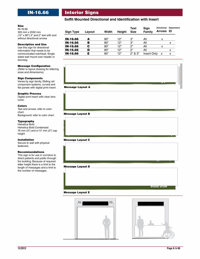
12/2012 Page 9-5-95
Interior SignsSoffitMountedDirectionalandIdentificationwithInsert
IN-16.66
Size IN-16.66 305 mm x 2032 mm (12" x 80") 3" and 2" text with and without directional arrows
DescriptionandUse Use this sign for directional information that needs to be communicated overhead. Single sided wall mount over header or doorway.
MessageConfiguration (Refer to layout drawing for lettering sizes and dimensions).
SignComponents Varies by sign family. Sliding rail component systems, curved and flat panels with digital print insert.
GraphicProcess Digital print Insert with clear lens cover.
Colors Text and arrows: refer to color chart. Background: refer to color chart.
Typography Helvetica Bold Helvetica Bold Condensed 76 mm (3") and or 51 mm (2") cap height
Installation Secure to wall with physical fasteners.
Recommendations This sign is for use in corridors to direct patients and public through the building. Because of required letter height there is a limit to the length of messages and a limit to the number of messages.
Message Layout A
Spinal RehabCanteen
UrologyPharmacy
Financial ManagementCLC Dining HallVeteran’s Business Center
Occupational TherapyImaging Center - Radiology
Blood Draw
Check-OutCheck-InEar, Nose & Throat
EQ. EQ.
Financial Management Occupational TherapyImaging Center - Radiology
Blood Draw
Imaging Services
EMERGENCY
Waiting Area 1PET Scan - CT Scan
Waiting Area 2Radiology - X Ray
Message Layout B
Message Layout C
Message Layout D
Message Layout E
Sign Type Layout Width Height Size Family
IN-16.66 A 80" 12" 3" All xIN-16.66 B 80" 12" 3" All xIN-16.66 C 80" 12" 2" All x IN-16.66 D 80" 12" 2" All xIN-16.66 E 80" 12" 2" & 3" Insert Only x x
Text Sign Department
IDDirectional
Arrows
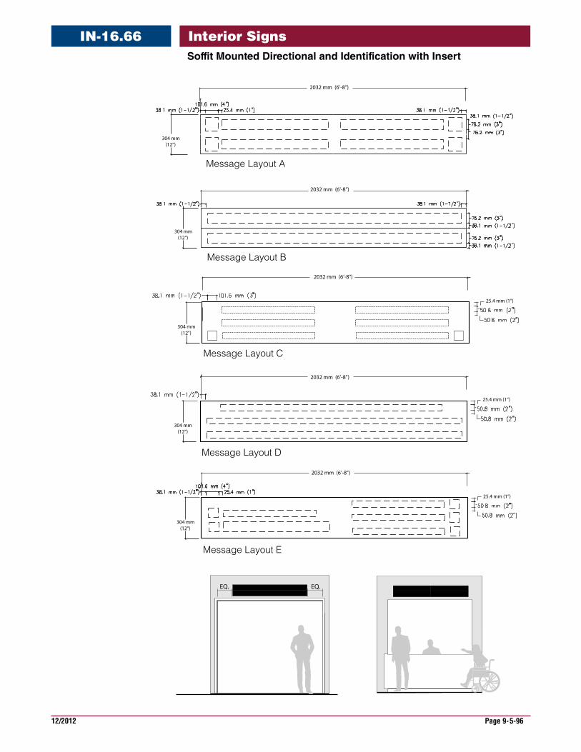
12/2012 Page 9-5-96
Interior SignsSoffitMountedDirectionalandIdentificationwithInsert
IN-16.66
Message Layout B
Message Layout C
Message Layout A
304 mm (12”)
304 mm (12”)
Message Layout D
304 mm (12”)
304 mm (12”)
Message Layout E
2032 mm (6’-8”)
304 mm (12”)
2032 mm (6’-8”)
2032 mm (6’-8”)
2032 mm (6’-8”)
2032 mm (6’-8”)
25.4 mm (1”)
25.4 mm (1”)
25.4 mm (1”)
EQ. EQ.
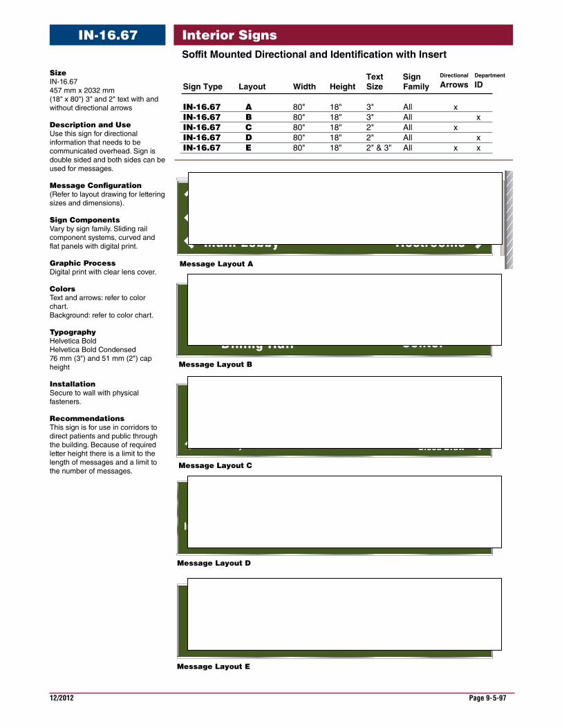
12/2012 Page 9-5-97
Interior SignsSoffitMountedDirectionalandIdentificationwithInsert
IN-16.67
Size IN-16.67 457 mm x 2032 mm (18" x 80") 3" and 2" text with and without directional arrows
DescriptionandUse Use this sign for directional information that needs to be communicated overhead. Sign is double sided and both sides can be used for messages.
MessageConfiguration (Refer to layout drawing for lettering sizes and dimensions).
SignComponents Vary by sign family. Sliding rail component systems, curved and flat panels with digital print.
GraphicProcess Digital print with clear lens cover.
Colors Text and arrows: refer to color chart. Background: refer to color chart.
Typography Helvetica Bold Helvetica Bold Condensed 76 mm (3") and 51 mm (2") cap height
Installation Secure to wall with physical fasteners.
Recommendations This sign is for use in corridors to direct patients and public through the building. Because of required letter height there is a limit to the length of messages and a limit to the number of messages.
Message Layout A
Spinal RehabCanteen
UrologyPharmacy
Message Layout C
Occupational TherapyImaging Center - Radiology
Blood Draw
Message Layout B
Veteran’s Business Center
CLC Dining Hall
Community Services
Message Layout E
Message Layout D
Security Alert
Main Lobby Restrooms
Mental HealthSecurityAccounting - CashierPharmacy
Imaging ServicesRegistrationAll visitors must check in
Waiting Area 2Wait for number to be called
Persons entering this property consent to an inspection of all packages,
luggage & containers in their possession. Refusal of consent to search is basis
for denial of admittance. See Security Of�cers for details of security policy.
Sign Type Layout Width Height Size Family
IN-16.67 A 80" 18" 3" All xIN-16.67 B 80" 18" 3" All xIN-16.67 C 80" 18" 2" All x IN-16.67 D 80" 18" 2" All xIN-16.67 E 80" 18" 2" & 3" All x x
Text Sign Department
IDDirectional
Arrows

12/2012 Page 9-5-98
Interior SignsSoffitMountedDirectionalandIdentificationwithInsert
IN-16.67
Message Layout C
Message Layout D
Message Layout B
Message Layout A
457
457
457
457
1 - 1/2
2134 mm (6’-8")
Message Layout E
2032 mm (6’-8”)
2032 mm (6’-8”)
2032 mm (6’-8”)
2032 mm (6’-8”)
EQ. EQ.
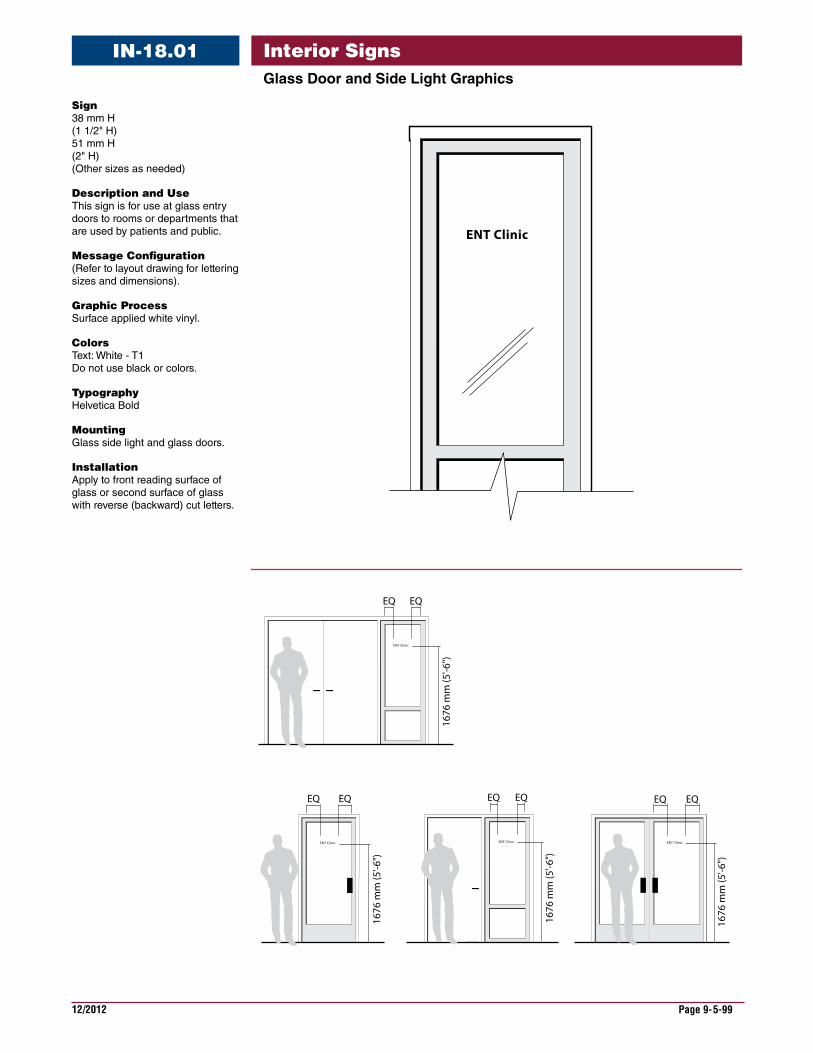
12/2012 Page 9-5-99
Interior SignsGlassDoorandSideLightGraphics
IN-18.01
ENT Clinic
EQ EQ
1676
mm
(5'-6
")
ENT Clinic
EQ EQ
1676
mm
(5'-6
")
ENT Clinic
EQEQ
1676
mm
(5'-6
")
ENT Clinic
EQ EQ
1676
mm
(5'-6
")
ENT Clinic
Sign 38 mm H (1 1/2" H) 51 mm H (2" H) (Other sizes as needed)
DescriptionandUse This sign is for use at glass entry doors to rooms or departments that are used by patients and public.
MessageConfiguration (Refer to layout drawing for lettering sizes and dimensions).
GraphicProcess Surface applied white vinyl.
Colors Text: White - T1 Do not use black or colors.
Typography Helvetica Bold
Mounting Glass side light and glass doors.
Installation Apply to front reading surface of glass or second surface of glass with reverse (backward) cut letters.
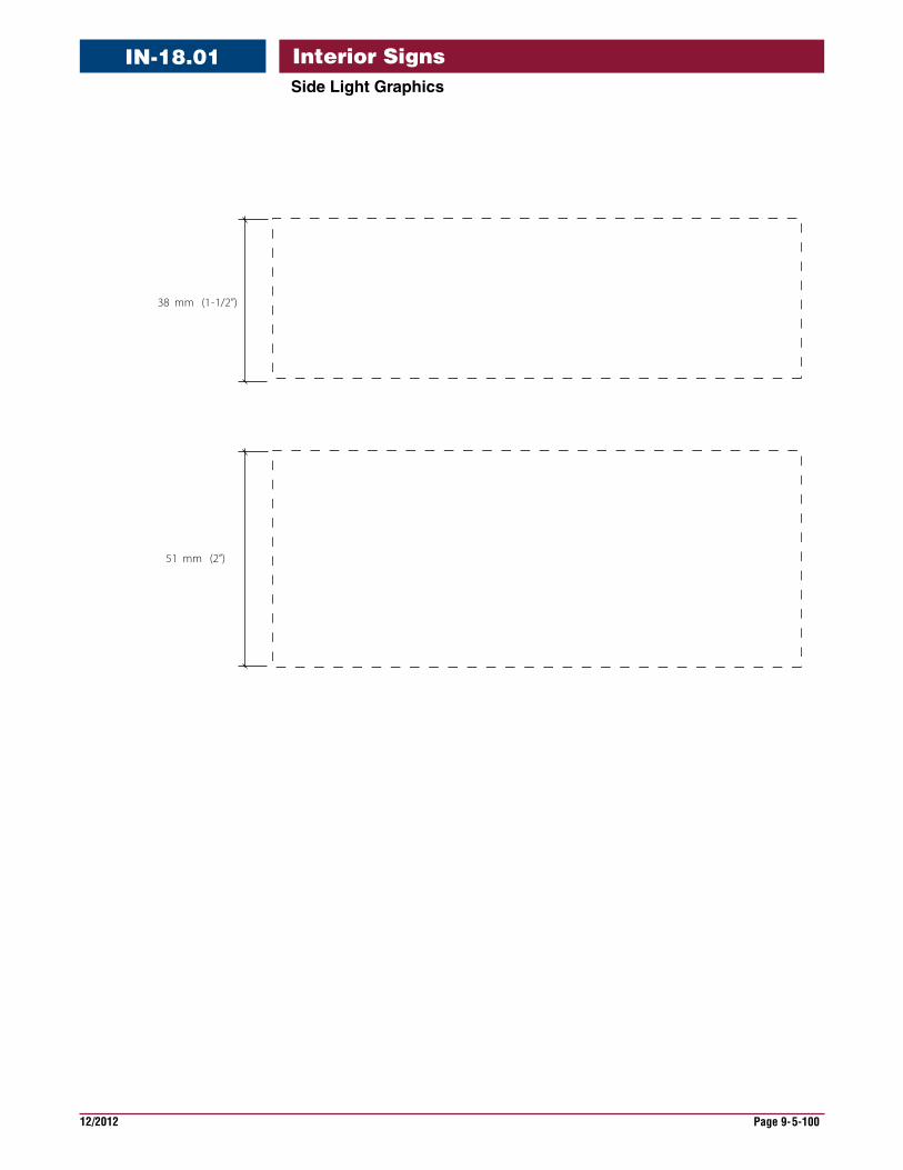
12/2012 Page 9-5-100
Interior SignsSideLightGraphics
IN-18.01
38 mm (1-1/2”)
51 mm (2”)
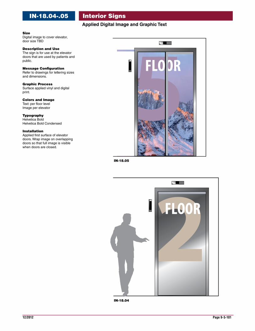
12/2012 Page 9-5-101
Interior SignsIN-18.04-.05
IN-18.04
IN-18.05
Size Digital image to cover elevator, door size TBD
DescriptionandUse The sign is for use at the elevator doors that are used by patients and public.
MessageConfiguration Refer to drawings for lettering sizes and dimensions.
GraphicProcess Surface applied vinyl and digital print.
ColorsandImage Text: per floor level Image per elevator
Typography Helvetica Bold Helvetica Bold Condensed
Installation Applied first surface of elevator doors. Wrap image on overlapping doors so that full image is visible when doors are closed.
AppliedDigitalImageandGraphicText
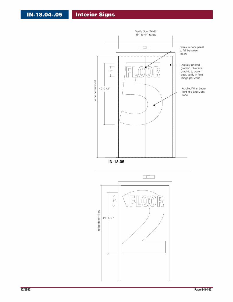
12/2012 Page 9-5-102
Interior SignsIN-18.04-.05
8"
49-1/2"
to b
e de
term
ined
Digitally printedgraphic. Oversizegraphic to coverdoor. verify in fieldImage per Zone
Break in door panel to fall between letters
8"
49-1/2"
to b
e de
term
ined
IN-18.04
IN-18.05
Applied Vinyl Letter Text Mid and Light Tone
Verify Door Witdth54” to 44” range
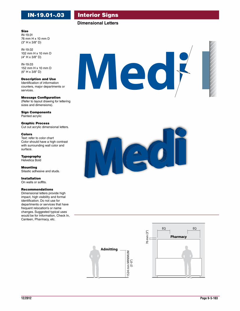
12/2012 Page 9-5-103
Interior SignsDimensionalLetters
IN-19.01-.03
Size IN-19.01 76 mm H x 10 mm D (3" H x 3/8" D)
IN-19.02 102 mm H x 10 mm D (4" H x 3/8" D)
IN-19.03 152 mm H x 10 mm D (6" H x 3/8" D)
DescriptionandUse Identification of information counters, major departments or services.
MessageConfiguration (Refer to layout drawing for lettering sizes and dimensions).
SignComponents Painted acrylic
GraphicProcess Cut out acrylic dimensional letters.
Colors Text: refer to color chart Color should have a high contrast with surrounding wall color and surface.
Typography Helvetica Bold
Mounting Silastic adhesive and studs.
Installation On walls or soffits.
Recommendations Dimensional letters provide high impact, high visibility and formal identification. Do not use for departments or services that have frequent relocation’s or name changes. Suggested typical uses would be for Information, Check In, Canteen, Pharmacy, etc.
1524
mm
MIN
IMU
M (5
'-0")
Admitting
Pharmacy
Medi
EQ
76 m
m (3
")
EQ

12/2012 Page 9-5-104
Interior SignsDimensionalLetters
IN-19.01-.03
IN-19.01
IN-19.02
IN-19.03
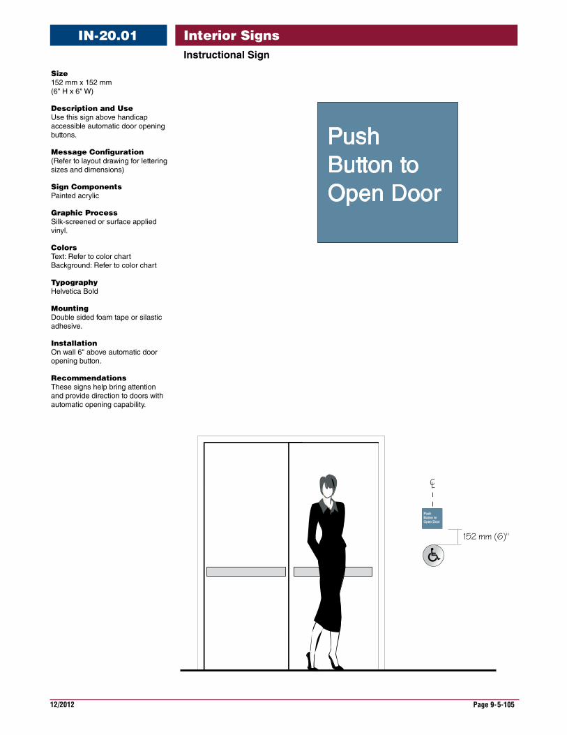
12/2012 Page 9-5-105
Interior SignsInstructionalSign
IN-20.01
Size 152 mm x 152 mm (6" H x 6" W)
DescriptionandUse Use this sign above handicap accessible automatic door opening buttons.
MessageConfiguration (Refer to layout drawing for lettering sizes and dimensions)
SignComponents Painted acrylic
GraphicProcess Silk-screened or surface applied vinyl.
Colors Text: Refer to color chart Background: Refer to color chart
Typography Helvetica Bold
Mounting Double sided foam tape or silastic adhesive.
Installation On wall 6" above automatic door opening button.
Recommendations These signs help bring attention and provide direction to doors with automatic opening capability.
152 mm (6)"
CL
PushButton toOpen Door
PUSHBUTTON TO OPEN DOOR
PushButton toOpen Door
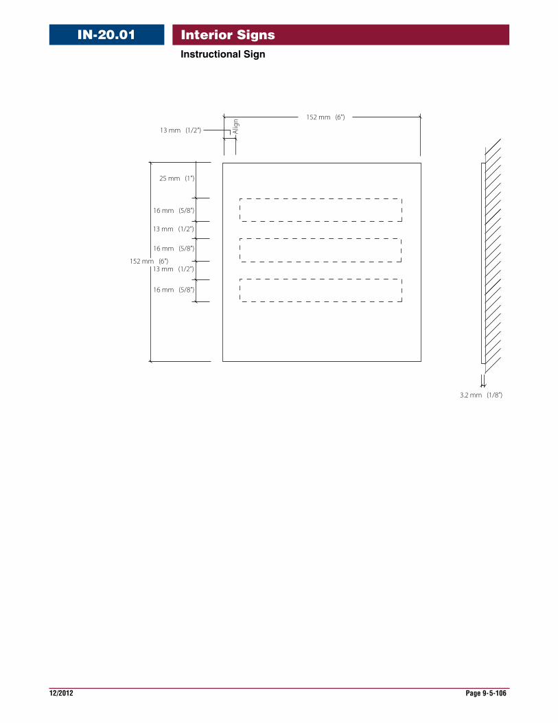
12/2012 Page 9-5-106
Interior SignsInstructionalSign
IN-20.01
3.2 mm (1/8”)
Alig
n
13 mm (1/2”)
152 mm (6”)
25 mm (1”)
16 mm (5/8”)
16 mm (5/8”)
16 mm (5/8”)
13 mm (1/2”)
13 mm (1/2”)152 mm (6”)
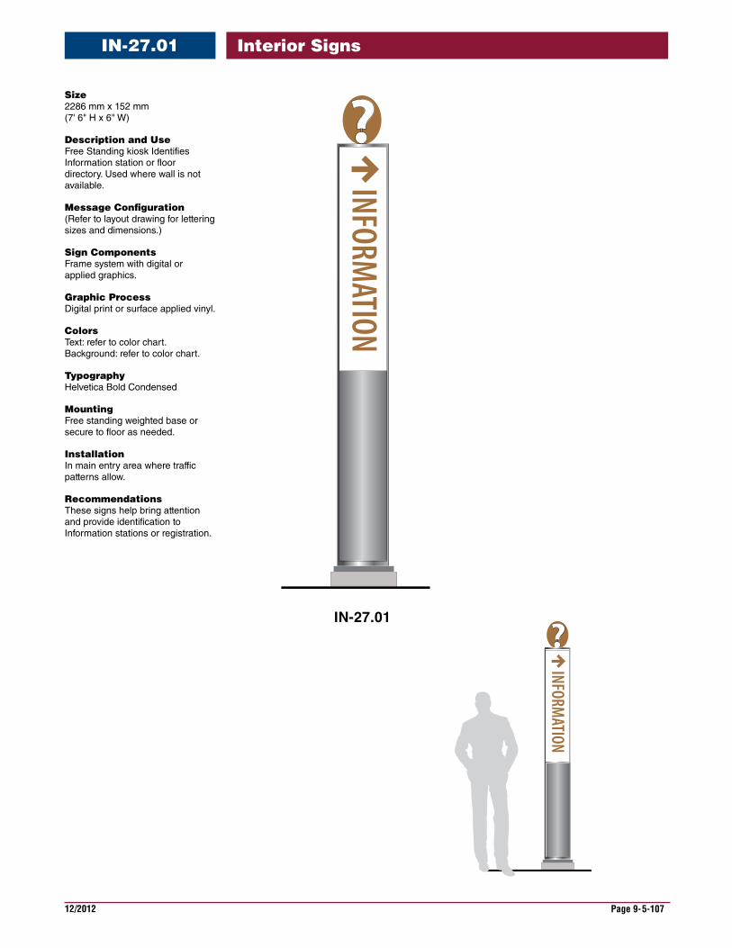
12/2012 Page 9-5-107
Interior SignsIN-27.01
Size 2286 mm x 152 mm (7' 6" H x 6" W)
DescriptionandUse Free Standing kiosk Identifies Information station or floor directory. Used where wall is not available.
MessageConfiguration (Refer to layout drawing for lettering sizes and dimensions.)
SignComponents Frame system with digital or applied graphics.
GraphicProcess Digital print or surface applied vinyl.
Colors Text: refer to color chart. Background: refer to color chart.
Typography Helvetica Bold Condensed
Mounting Free standing weighted base or secure to floor as needed.
Installation In main entry area where traffic patterns allow.
Recommendations These signs help bring attention and provide identification to Information stations or registration.
INFORMATION
INFORMATION
IN-27.01
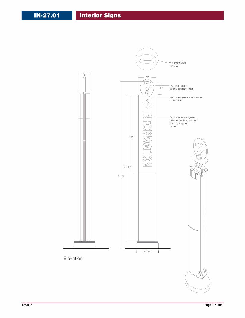
12/2012 Page 9-5-108
Interior Signs
3/8” aluminum bar w/ brushedsatin finish
1/2” thick letterssatin alluminum finish
Structure frame systembrushed satin aluminumwith digital printinsert
9"
6'-6"
7'-6”
6"
6"1"
1’-0"
Weighted Base
Elevation
42”
12” DIA
IN-27.01

12/2012 Page 9-6-1
Interior Signs
The specifications for signs are available in the Master Construction Specifications (PG-18-1) area of the VA Technical Information Library, which is available on the VA web site under Office of Construction & Facilities Management.
www.cfm.va.gov/til/
Refer to Signage in the specifications, Division 10, Section 10 14 00.
For more information regarding specifications, contact the Office of Construction & Facilities Management, Facility Standards Service.
The specifications require close coordination, taking into account the existing sign program at a medical center, any sign demolition, sign maintenance and future signing needs.
When preparing the specifications for a project, it will require editing to add and indicate new signs or eliminate signs that are not needed. Also, it will be necessary to adapt the specifications to project requirements required for the specific project in which they are intended.
The sign message schedule is considered a part of the specifications and would comprise a portion of the spec section. The configuration and format of the message schedule may vary according to individual project requirements. The sign message schedule for-mat is shown in the Need a Sign Program section of the VA Signage Design Guide. It pro-vides the method for identifying each sign location, type and message along with other notations. The sign schedule contains important information that the sign manufacturer and the sign installer will require for manufacturing and sign installation.
The sign message schedule must be coordinated with a sign location plan drawing showing where signs are to be placed within a building or on the site. Refer to the sign location plan example shown in the NeedaSignProgram section of the VA Signage Design Guide.
For convenience, the sign type drawings can also be included in the specifications as it own section.
Specifications

This page is intentionally left blank.
12/2012 Page 9-7-1
Interior Signs
The type of interior sign and sign system being selected for a particular application or fa-cility requires several decisions and involves different construction and assembly compo-nents to meet desired requirements. This section provides an overview of the intended criteria for interior sign programs.
Many sign manufacturers currently market extrusions, standard parts and component sign systems that meet the objectives of the intended interior sign system. These ex-truded, molded and fabricated component sign systems are acceptable as long as they conform to the illustrated and stated specifications.
The acrylic interior sign program, that has been in use since the 80’s, can easily be re-placed with a component system. A component sign program brings new products and solutions to meet various needs of the medical centers and are available from GSA ap-proved sign manufacturers and sign manufacturers in the open market place.
The details showing the construction of the component sign system sign types are based on a system of standard parts. The illustrations are intended to show desired configura-tions and the intent of various sign types.
Sections of the extrusions and various parts are for illustration purposes and have not been engineered or configured for extruding, and do not represent a finished form.
With the component system, variations such as beveled and radius shapes in the accent rails and end caps do not conform to the VA sign program.
Elimination of the old style radius corners reduces costs, provides more flexibility and al-low for the inter-changing of components.
Once a component system from a manufacturer is selected, it should become the stan-dard for the facility. The component system has been designed to be compatible with an existing old style acrylic system in size, however there will be a significant difference in appearance.
A component system encourages the ongoing updating and maintenance of the sign program to be done by the facility. The component system uses vinyl letters as the meth-od of producing the lettering. Engraving can also be used, but this increases the costs of the signs and the added cost does not provide significant benefits.
Using an insert style component system allows for the sign updates to be made by the facility using a digital or laser printer, allowing quick inexpensive updates.
The Specification section of the Guide should be read in conjunction with the Construction Details section. This will provide an overview of the interior sign construc-tion requirements, materials and finishes.
Construction
12/2012 Page 9-7-2
Interior Signs
The Guide illustrates component based sign systems for interior sign type families. Component systems use various interlocking elements which, when assembled, create a sign. They are available from several manufacturers and these general illustrations represent component systems that slide or snap together. The VA en-courages each facility to select the same component system to be used through-out all the buildings.
A benefit of the component system is that it provides flexibility and simplicity in maintaining and adapting signs to ever changing needs. Components from one sign can be interchanged with components from another sign, of the same sign type, quickly and easily. Existing signs can be added to, or modified to perform another function. Changing directional signs is simple and adding new text and ar-rows and rearranging messages is always possible.
Implementation of a component system requires commitment to a specific manu-facturer’s system. Carefully review the advantages and disadvantages of various components systems from different manufacturer’s, and contact facilities that have installed the system that is being considered.
In the following pages, the guide illustrates these sign systems:
•Sliding Rail Component System
•Frame Component Systems
•Insert and Frame Systems
•Curved Frame System
Construction
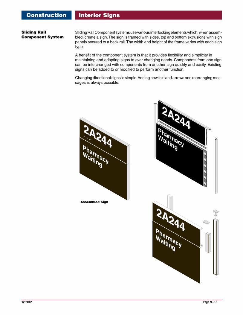
12/2012 Page 9-7-3
Interior Signs
Sliding Rail Component systems use various interlocking elements which, when assem-bled, create a sign. The sign is framed with sides, top and bottom extrusions with sign panels secured to a back rail. The width and height of the frame varies with each sign type.
A benefit of the component system is that it provides flexibility and simplicity in maintaining and adapting signs to ever changing needs. Components from one sign can be interchanged with components from another sign quickly and easily. Existing signs can be added to or modified to perform another function.
Changing directional signs is simple. Adding new text and arrows and rearranging mes-sages is always possible.
SlidingRailComponentSystem
Construction
Assembled Sign
2A244
PharmacyWaiting
2A244
PharmacyWaiting
2A244
2A244
PharmacyWaiting
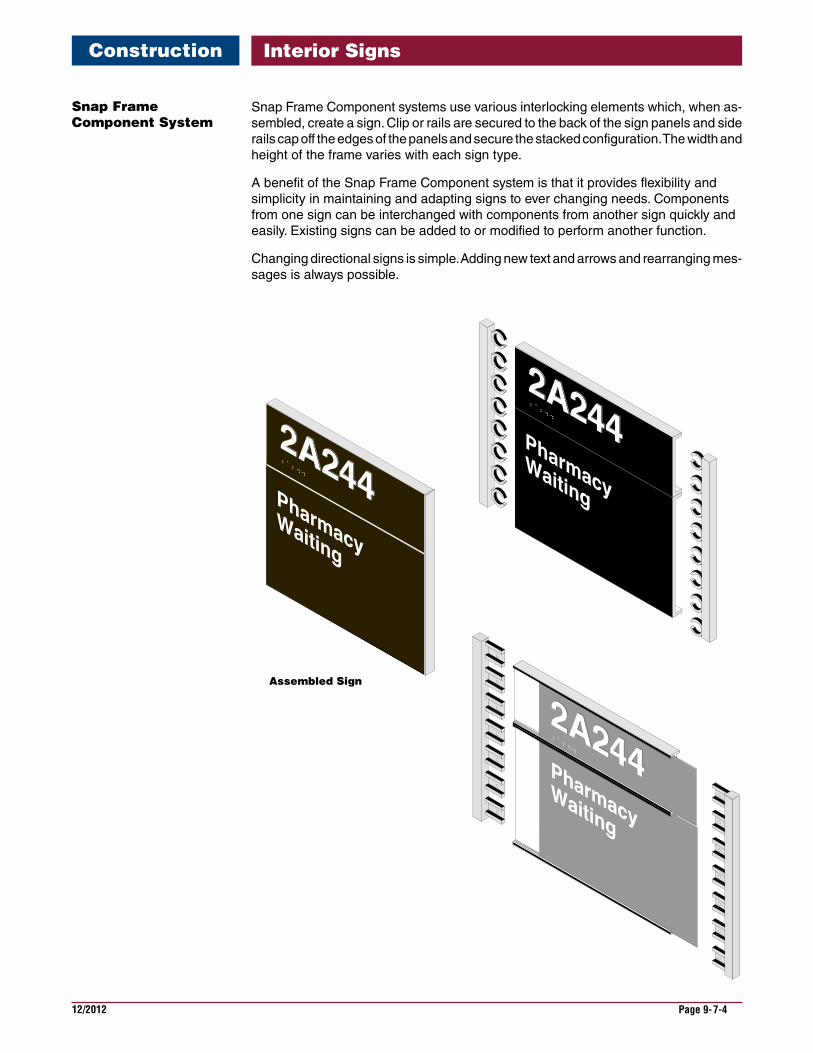
12/2012 Page 9-7-4
Interior Signs
Snap Frame Component systems use various interlocking elements which, when as-sembled, create a sign. Clip or rails are secured to the back of the sign panels and side rails cap off the edges of the panels and secure the stacked configuration. The width and height of the frame varies with each sign type.
A benefit of the Snap Frame Component system is that it provides flexibility and simplicity in maintaining and adapting signs to ever changing needs. Components from one sign can be interchanged with components from another sign quickly and easily. Existing signs can be added to or modified to perform another function.
Changing directional signs is simple. Adding new text and arrows and rearranging mes-sages is always possible.
SnapFrameComponentSystem
Construction
Assembled Sign
2A244
PharmacyWaiting
2A244
2A244
PharmacyWaiting
PharmacyWaiting
2A244
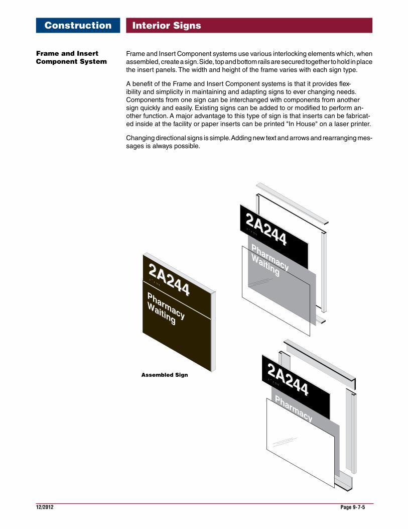
12/2012 Page 9-7-5
Interior Signs
Frame and Insert Component systems use various interlocking elements which, when assembled, create a sign. Side, top and bottom rails are secured together to hold in place the insert panels. The width and height of the frame varies with each sign type.
A benefit of the Frame and Insert Component systems is that it provides flex-ibility and simplicity in maintaining and adapting signs to ever changing needs. Components from one sign can be interchanged with components from another sign quickly and easily. Existing signs can be added to or modified to perform an-other function. A major advantage to this type of sign is that inserts can be fabricat-ed inside at the facility or paper inserts can be printed "In House" on a laser printer.
Changing directional signs is simple. Adding new text and arrows and rearranging mes-sages is always possible.
FrameandInsertComponentSystem
Construction
Assembled Sign
2A244
PharmacyWaiting
2A244
PharmacyWaiting
2A244
PharmacyWaiting
2A244
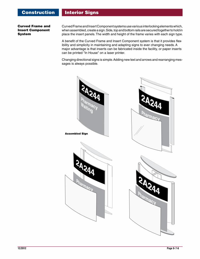
12/2012 Page 9-7-6
Interior Signs
Curved Frame and Insert Component systems use various interlocking elements which, when assembled, create a sign. Side, top and bottom rails are secured together to hold in place the insert panels. The width and height of the frame varies with each sign type.
A benefit of the Curved Frame and Insert Component system is that it provides flex-ibility and simplicity in maintaining and adapting signs to ever changing needs. A major advantage is that inserts can be fabricated inside the facility, or paper inserts can be printed "In House" on a laser printer.
Changing directional signs is simple. Adding new text and arrows and rearranging mes-sages is always possible.
CurvedFrameandInsertComponentSystem
Construction
Assembled Sign
2A244
2A244
2A244
2A244
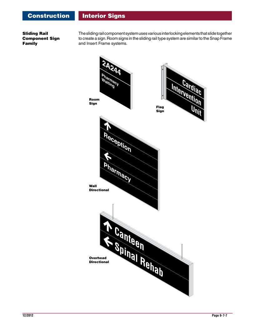
12/2012 Page 9-7-7
Interior Signs
SlidingRailComponentSignFamily
CardiacIntervention
Unit
Pharmacy
Reception
CanteenSpinal Rehab
2A244
PharmacyWaiting
2A244
Room Sign
WallDirectional
OverheadDirectional
Flag Sign
Construction
The sliding rail component system uses various interlocking elements that slide together to create a sign. Room signs in the sliding rail type system are similar to the Snap Frame and Insert Frame systems.
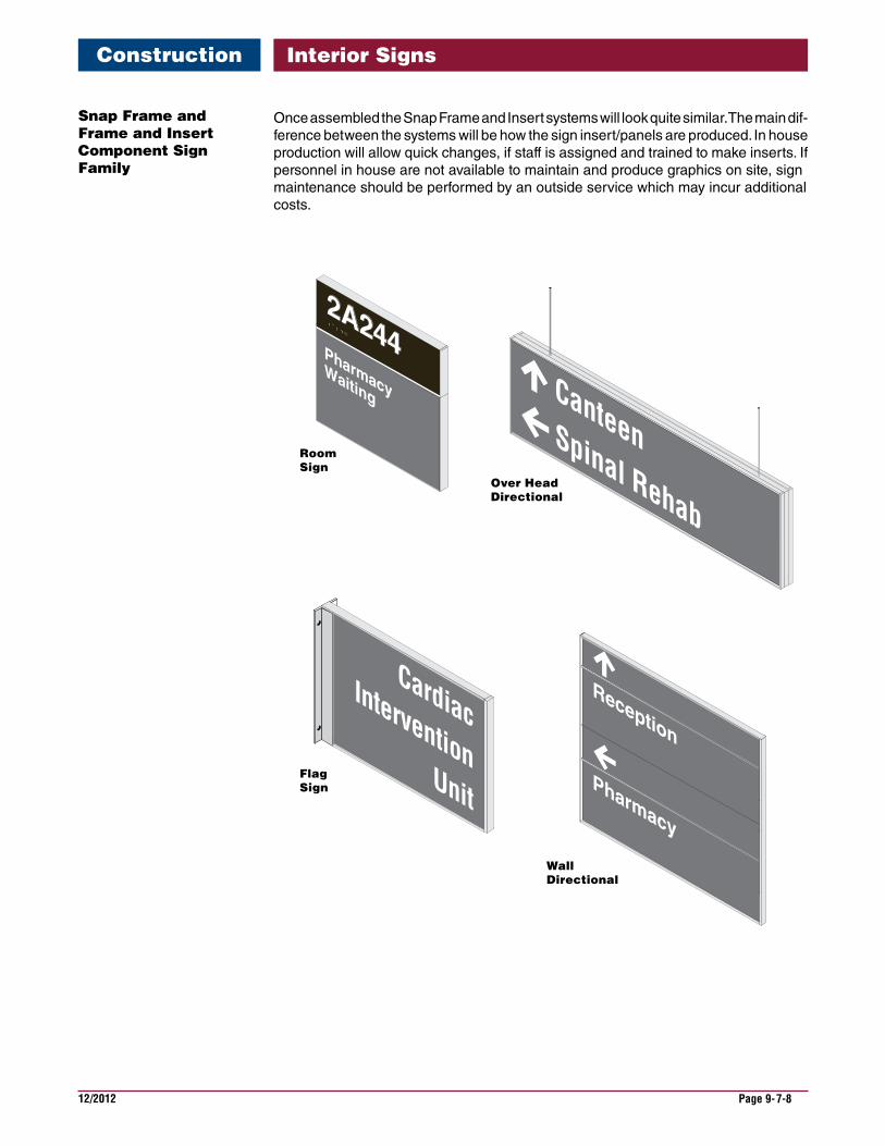
12/2012 Page 9-7-8
Interior Signs
SnapFrameandFrameandInsertComponentSignFamily
2A244
PharmacyWaiting
2A244
CardiacIntervention
UnitPharmacy
Reception
CanteenSpinal Rehab
Room Sign
Over HeadDirectional
WallDirectional
Flag Sign
Once assembled the Snap Frame and Insert systems will look quite similar. The main dif-ference between the systems will be how the sign insert/panels are produced. In house production will allow quick changes, if staff is assigned and trained to make inserts. If personnel in house are not available to maintain and produce graphics on site, sign maintenance should be performed by an outside service which may incur additional costs.
Construction

12/2012 Page 9-7-9
Interior Signs
CurvedFrameandInsertSignFamily
2A244
Room Sign
FlagSign
Wall Directional
Over Head Directional
Construction
Curved Frame and Insert component systems are available to support a variety of sign types required to program a facility. Shapes and assembly methods vary by manufacturer. The style of frames also varies, therefore research the desired "look" before proceeding to order.
This page is intentionally left blank.
12/2012 Page 9-8-1
Interior Signs
The installation of interior signs requires coordination of several interlaced criteria. Interior signs, especially directional signs, require coordination and careful consideration of the following:
•Location of building entrances and elevators.
•Configuration of the corridor system.
•Desired path of travel within the building for visitors, patients and employees.
•Location of departments and clinics.
•A simple clear room numbering system that follows a clear,understandable pattern.
•Adequate light on and around directional signs.
Placement of signs in locations where people are expecting them to be.
These elements help establish the basis of a clear sign program that communicates and informs in a direct and simple manner.
Interior signs function to communicate to both patients, visitors and staff. Their place-ments must be planned relative to the intended viewer, particularly the directional signs. Sign visibility to the intended user is a principal objective that forms the basis of correct sign placement.
Proper sign placement is part of a well-planned interior sign program.
In order to meet ABA/ADA guidelines, tactile room number signs must now always be specifically placed on the wall, on the strike/knob side of the door. Ceiling mounted signs require large lettering size, therefore, only short selective messages can be communicated.
Correct placement of signs will usually require fewer signs. Too many signs can create clutter and increase the difficulty for a viewer to find the particular information they are seeking. Placement of signs where there is sufficient lighting is critical.
Color selection is an element of the wayfinding system that effects the visibility of signs. Putting directional signs in a color that is different from room identification signs can be helpful to patients and visitors. Consistent use of sign color for a particular type of mes-sage reinforces the effectiveness of the sign program.
A sign program for a building, that works well, is one that has been planned as an inte-grated whole. All the way from the main entrance sign, to directional signs, room identifi-cation signs, informational signs, code required signs and life safety signs.
Criteria
Visibility
Placement
Planning
Installation
12/2012 Page 9-8-2
Interior SignsInstallation
Different types of signs require different installation techniques, depending on their ap-plication or use, weight or size and whether the sign needs to be removed at some point in the future. Wall surfaces and materials need to be taken into consideration when de-ciding on the method to use.
Types of ceilings can have an impact on signage installation, particularly in regard to accessibility. Hard ceiling access to sign locations can be a problem if there is not an ac-cess door close to the sign location. Interlocking tile and T bar ceiling should not have signs directly attached to them as they are not designed to carry the weight of a sign. Additionally, they are not stable with additional sign loads in the event of earthquakes or severe storms.
Double Sided Tape: is a common method to adhere small signs to an interior wall. The tape is quick, inexpensive and durable for most interior signs. There are two types of double sided tape. Double sided foam tape for light to medium duty applications and VHB (very high bond) double-sided acrylic tape heavy duty applications. Double-sided tape will stick to most surfaces with one exception. When adhering a sign to vinyl wall covering it is necessary to add a silicone adhesive to the back of the sign. The problem with using double sided tape is often the painted surface, or wall papered surface, will be damaged when a sign is removed.
Silastic Adhesive: is another quick and inexpensive way to install interior signs. A small piece of double sided tape is applied to the back of the sign or masking tape adhered to the front of the sign is used to hold the sign in place until the silicone sets. The drawback of using silicone is the odor the silicone emits until it has completely cured and hard-ened. A small amount of wall damage can be expected when removing the sign.
Mechanical fastener or screw mounting: is the strongest method for installing interior signs. Typically interior signs are lightweight enough and do not require this. When using wall anchors it is suggested that the fasteners penetrate a stud or backer behind the wall. An alternative to this would be using a hollow wall anchor. Screw mounting can pro-hibit vandalism to a certain degree, which can be taken one step further if tamper-proof fasteners are used. A benefit of using fasteners is it is only necessary to patch the small holes that remain when a sign is removed.
Projecting signs must always be mechanically fastened to the wall with wall anchors penetrating a solid substrate such as a stud or backing material behind the wall. In cor-ridors a flag mounted sign shall always be placed with the bottom of the sign height at 84" for clearance of pedestrians and equipment.
Signs mounted above the pedestrian path of travel shall always be mechanically fas-tened to a solid substrate. These signs shall not be attached to the drop down T-bar ceil-ing grid. Typically, the placement of ceiling mounted signs are in the center of a corridor or over the pedestrian path of travel. Proper overhead clearance (84" minimum) must be maintained for clear path of travel for pedestrians and equipment.
Illuminated exit signs should not be blocked by ceiling signs and fire sprinkler heads should not have their spray pattern impacted by a ceiling sign. Sprinkler systems, exit signs, and other ceiling mounted items also must not block the clear viewing area of the sign. The sign should be relocated in any of these situations.
InstallationMethodsandTechniquesBuildings
WallSigns
FlagMountedProjectingSigns
CeilingMountedSigns
12/2012 Page 9-8-3
Interior SignsInstallation
Vinyl lettering can be installed on most hard clean surfaces. Plastic and glass should be cleaned and any dry matter, such as tape or glue, removed. Freshly painted surfaces should be allowed to dry for at least 72 hours prior to the appli-cation of vinyl graphics. This will allow any vapors to dissipate from the paint as it cures.
Dimensional letters can be installed on most hard clean surfaces. Letters can be mounted with double sided tape or an adhesive appropriate for the wall surface. Typically letters larger that 4 inches also have studs attached to the back. These studs are imbedded into the wall surface to support the weight of the letters. Studs must be used when a surface is rough and high textured
Height of tactile signs with Braille require specific placement and must conform to the Americans with Disabilities Act. Please refer to Accessibility requirements in another section of this Guide, and refer to the interior installation drawings at the rear of this chapter
VinylLetteringandGraphics
DimensionalLetters
RoomIdentificationSigns
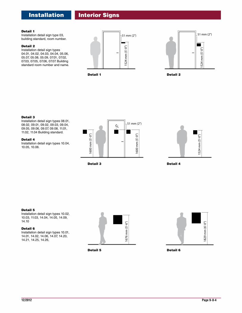
12/2012 Page 9-8-4
Interior Signs
Detail1 Installation detail sign type 03, building standard, room number.
Detail2 Installation detail sign types 04.01, 04.02, 04.03, 04.04, 05.06, 05.07, 05.08, 05.09, 07.01, 07.02, 07.03, 07.05, 07.06, 07.07. Building standard room number and name.
Detail3 Installation detail sign types 08.01, 08.02, 09.01, 09.02, 09.03, 09.04, 09.05, 09.06, 09.07, 09.08, 11.01, 11.02, 11.04 Building standard.
Detail4 Installation detail sign types 10.04, 10.05, 10.06.
Detail5 Installation detail sign types 10.02, 10.03, 11.03, 14.04, 14.05, 14.09, 14.10
Detail6 Installation detail sign types 10.01, 14.01, 14.02, 14.06, 14.07, 14.20, 14.21, 14.25, 14.26,
Installation
51 mm (2")
1524
mm
(5'-0
")
51 mm (2")
1524
mm
(5'-0
")
1676
mm
(5'-6
")
1829
mm
(6'-0
")
1524
mm
(5'-0
")
51 mm (2")CL
1600
mm
(5'-0
")
1600
mm
(5'-0
")
Detail 1 Detail 2
Detail 3 Detail 4
Detail 5 Detail 6
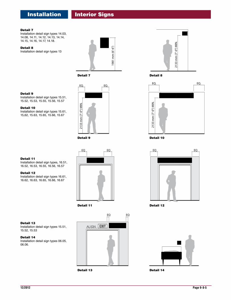
12/2012 Page 9-8-5
Interior Signs
Detail7 Installation detail sign types 14.03, 14.08, 14.11, 14.12, 14.13, 14.14, 14.15, 14.16, 14.17, 14.18.
Detail8 Installation detail sign types 13
Detail9 Installation detail sign types 15.51, 15.52, 15.53, 15.55, 15.56, 15.57
Detail10 Installation detail sign types 15.61, 15,62, 15.63, 15.65, 15.66, 15.67
EQ. EQ.21
33 m
m (7
'-0")
MIN
.
EQ EQ
EQ. EQ.
2133
mm
(7'-0
") M
IN.
EQ EQ
EXIT
EQ EQ
ALIGN
1981
mm
(6'-6
")
2133
mm
(7'-0
") M
IN.
Detail 7 Detail 8
Detail 9 Detail 10
Detail 11 Detail 12
Detail 13 Detail 14
Detail11 Installation detail sign types, 16.51, 16.52, 16.53, 16.55, 16.56, 16.57
Detail12 Installation detail sign types 16.61, 16.62, 16.63, 16.65, 16.66, 16.67
Detail13 Installation detail sign types 15.51, 15.52, 15.53
Detail14 Installation detail sign types 06.05, 06.06.
Installation
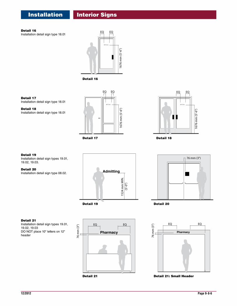
12/2012 Page 9-8-6
Interior Signs
Detail16 Installation detail sign type 18.01
EQ EQ
1676
mm
(5'-6
")
ENT Clinic
EQ EQ
1676
mm
(5'-6
")
ENT Clinic
EQEQ
1676
mm
(5'-6
")
ENT Clinic
76 mm (3")
1524
mm
MIN
. (5
'-0")
Admitting
Detail 16
Detail 17 Detail 18
Detail 19 Detail 20
Pharmacy
EQ
76 m
m (3
") EQ
Pharmacy
EQ
76 m
m (3
") EQ
Detail 21 Detail 21: Small Header
Detail17 Installation detail sign type 18.01
Detail18 Installation detail sign type 18.01
Detail19 Installation detail sign types 19.01, 19.02, 19.03.
Detail20 Installation detail sign type 08.02.
Detail21 Installation detail sign types 19.01, 19.02, 19.03 DO NOT place 10" letters on 12" header
Installation
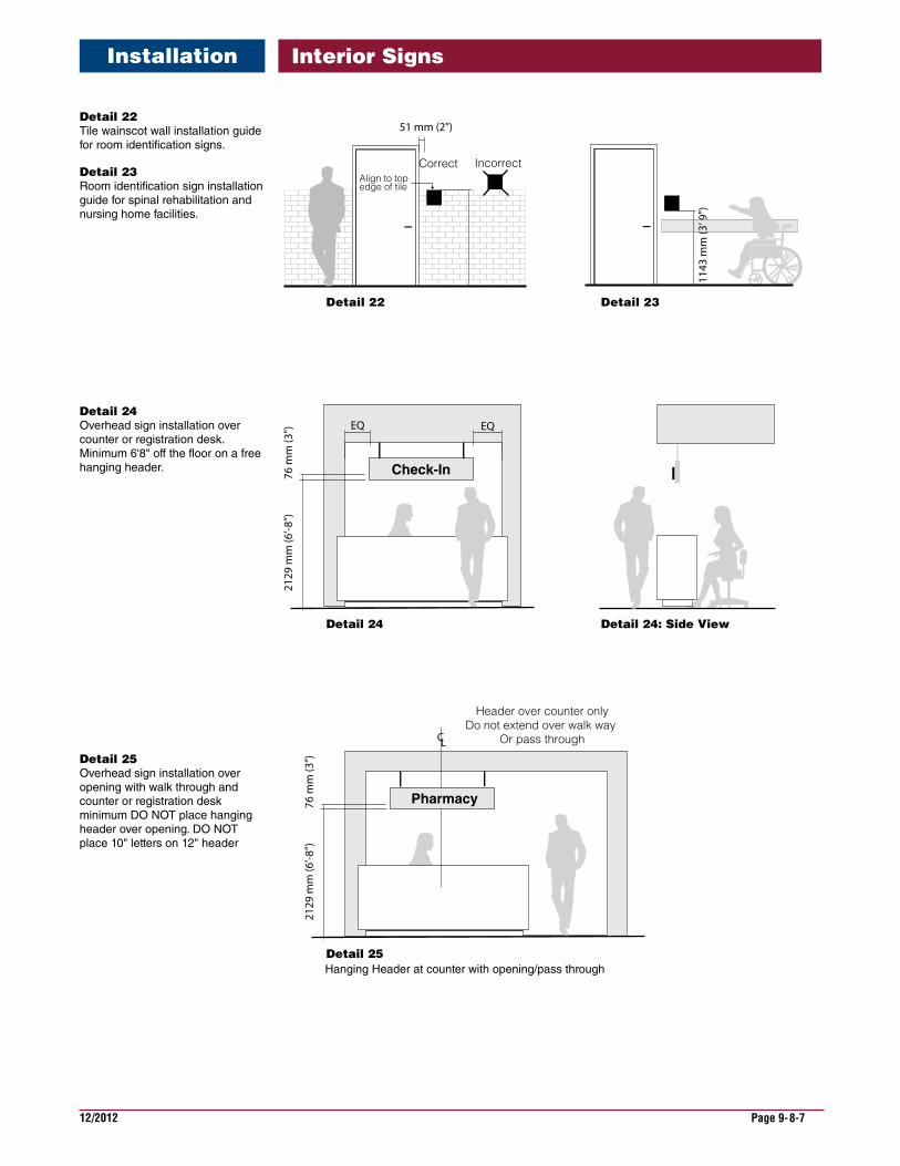
12/2012 Page 9-8-7
Interior Signs
EQ
76 m
m (3
") EQ
Check-In
2129
mm
(6’-8
”)
76 m
m (3
")
Header over counter onlyDo not extend over walk way
Or pass through
Pharmacy
2129
mm
(6’-8
”)
CL
Detail 24
Detail 25Hanging Header at counter with opening/pass through
Detail 24: Side View
1143
mm
(3’ 9
")
51 mm (2")
Correct IncorrectAlign to top edge of tile
Detail 22 Detail 23
Detail22 Tile wainscot wall installation guide for room identification signs.
Detail23 Room identification sign installation guide for spinal rehabilitation and nursing home facilities.
Installation
Detail24 Overhead sign installation over counter or registration desk. Minimum 6'8" off the floor on a free hanging header.
Detail25 Overhead sign installation over opening with walk through and counter or registration desk minimum DO NOT place hanging header over opening. DO NOT place 10" letters on 12" header

12/2012 Page 9-8-8
Interior Signs
Check-In
Minimum distance from bottom of sign to floor 7’-4”
Overhead sign with installed in Lobby or Waiting areas with valted ceiling.
Maximum ceiling height of 12’ for overhead hung signs. Distance from bottom of sign to floor to bemax. 8”-0”
Check-In
8'-0"
Detail26 Overhead hanging sign Lobby or waiting room with high ceiling. DO NOT install hanging sign in areas with ceilings higher than 12'-0”. Use a wall mount flag sign.
Installation
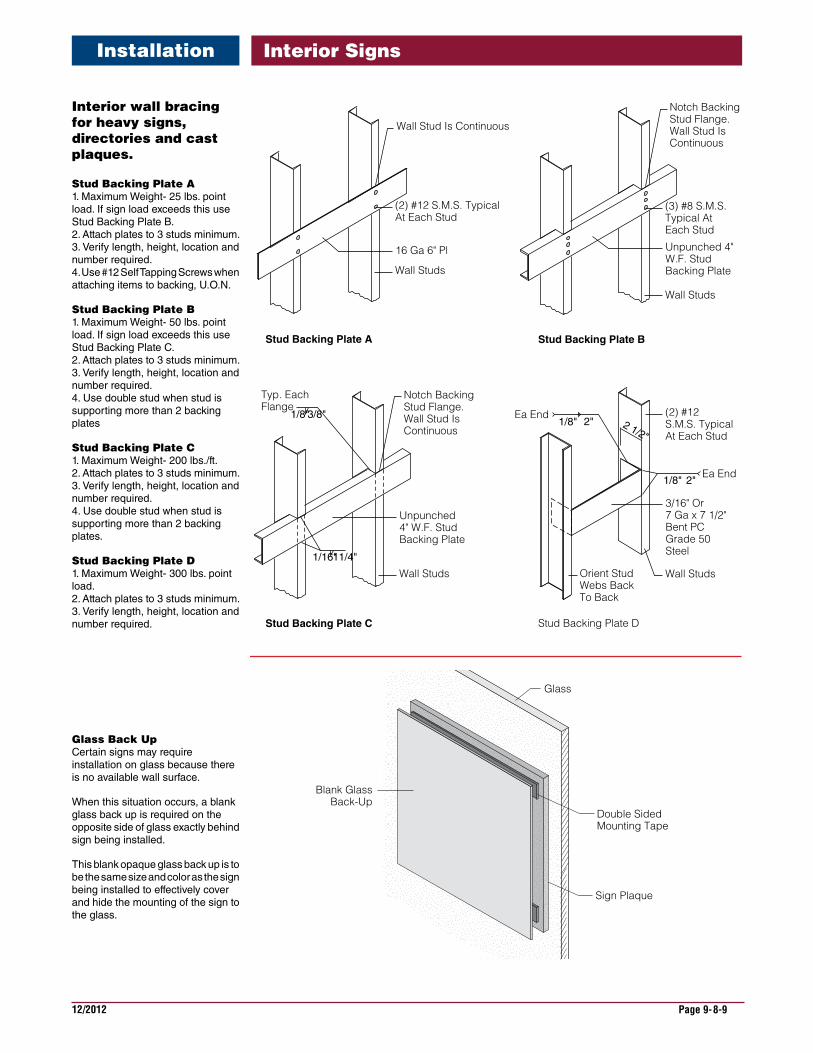
12/2012 Page 9-8-9
Interior Signs
Wall Studs
Wall Stud Is Continuous
(2) #12 S.M.S. TypicalAt Each Stud
16 Ga 6" Pl
Stud Backing Plate A
Wall Studs
Notch BackingStud Flange. Wall Stud Is Continuous
(3) #8 S.M.S. Typical At Each Stud
Unpunched 4" W.F. StudBacking Plate
Stud Backing Plate B
Wall Studs
(2) #12 S.M.S. TypicalAt Each Stud
3/16" Or 7 Ga x 7 1/2"Bent PC Grade 50Steel
2 1/2"
Orient Stud Webs Back To Back
Ea End2"1/8"
Ea End1/8" 2"
Stud Backing Plate D
Wall Studs
Notch BackingStud Flange. Wall Stud Is Continuous
Typ. EachFlange
Unpunched 4" W.F. StudBacking Plate
1/8"3/8"
1/16"11/4"
Stud Backing Plate C
Sign Plaque
Glass
Double SidedMounting Tape
Blank GlassBack-Up
Interiorwallbracingforheavysigns,directoriesandcastplaques.
StudBackingPlateA 1. Maximum Weight- 25 lbs. point load. If sign load exceeds this use Stud Backing Plate B. 2. Attach plates to 3 studs minimum. 3. Verify length, height, location and number required. 4. Use #12 Self Tapping Screws when attaching items to backing, U.O.N.
StudBackingPlateB 1. Maximum Weight- 50 lbs. point load. If sign load exceeds this use Stud Backing Plate C. 2. Attach plates to 3 studs minimum. 3. Verify length, height, location and number required. 4. Use double stud when stud is supporting more than 2 backing plates
StudBackingPlateC 1. Maximum Weight- 200 lbs./ft. 2. Attach plates to 3 studs minimum. 3. Verify length, height, location and number required. 4. Use double stud when stud is supporting more than 2 backing plates.
StudBackingPlateD 1. Maximum Weight- 300 lbs. point load. 2. Attach plates to 3 studs minimum. 3. Verify length, height, location and number required.
Installation
GlassBackUp Certain signs may require installation on glass because there is no available wall surface.
When this situation occurs, a blank glass back up is required on the opposite side of glass exactly behind sign being installed.
This blank opaque glass back up is to be the same size and color as the sign being installed to effectively cover and hide the mounting of the sign to the glass.
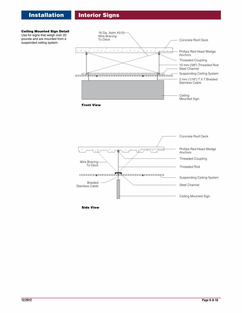
12/2012 Page 9-8-10
Interior Signs
CeilingMountedSignDetail Use for signs that weigh over 20 pounds and are mounted from a suspended ceiling system.
Concrete Roof Deck
Phillips Red Head Wedge Anchors
Threaded Coupling
Threaded Rod
Wire BracingTo Deck
Steel Channel
Suspending Ceiling System
BraidedStainless Cable
Ceiling Mounted Sign
Side View
Front View
Concrete Roof Deck
Phillips Red Head Wedge Anchors
Threaded Coupling
10 mm (3/8") Threaded Rod
16 Ga. Astm A510 Wire Bracing To Deck
Steel ChannelSuspending Ceiling System
2 mm (1/16") 7 X 7 Braided Stainless Cable
Ceiling Mounted Sign
Installation
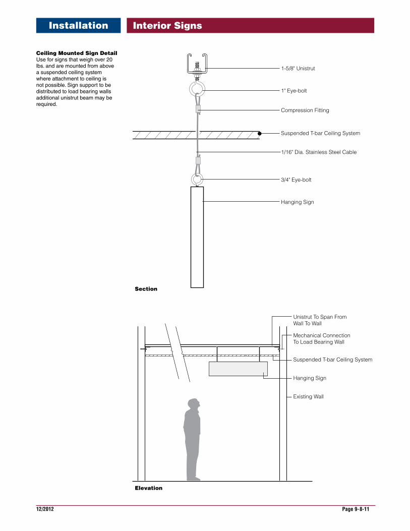
12/2012 Page 9-8-11
Interior Signs
Elevation
Section
Unistrut To Span From Wall To Wall
Suspended T-bar Ceiling System
Hanging Sign
Existing Wall
Mechanical ConnectionTo Load Bearing Wall
1-5/8" Unistrut
1/16" Dia. Stainless Steel Cable
Suspended T-bar Ceiling System
Hanging Sign
1" Eye-bolt
Compression Fitting
3/4" Eye-bolt
CeilingMountedSignDetail Use for signs that weigh over 20 lbs. and are mounted from above a suspended ceiling system where attachment to ceiling is not possible. Sign support to be distributed to load bearing walls additional unistrut beam may be required.
Installation