vac clad-w electricalpartmanuals . · · 2014-03-24cl april 1990 supersedes renewal parts data...
TRANSCRIPT
Cl
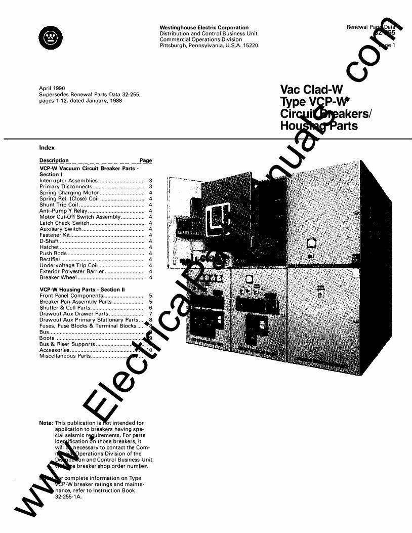
April 1990 Supersedes Renewal Parts Data 32-255, pages 1 -12, dated January, 1 988
Index
Description Page
VCP-W Vacuum Circuit Breaker Parts -Section I Interrupter Assemblies............................... 3 Primary Disconnects................................... 3 Spring Charging Motor.............................. 4 Spring Rei. (Close) Coil .............................. 4 Shunt Trip Coil............................................ 4 Anti-Pump Y Relay...................................... 4 Motor Cut-Off Switch Assembly ................ 4 Latch Check Switch..................................... 4 Auxiliary Switch.......................................... 4 Fastener Kit.................................................. 4 D-Shaft ......................................................... 4 Hatchet ......................................................... 4 Push Rods .................................................... 4 Rectifier........................................................ 4 Undervoltage Trip Coil............................... 4 Exterior Polyester Barrier........................... 4 Breaker Wheel .. . ... .......... .... .... ...... .......... ..... 4
VCP-W Housing Parts - Section II Front Panel Components............................ 5 Breaker Pan Assembly Parts...................... 5 Shutter & Cell Parts.................................... 6 Drawout Aux Drawer Parts........................ 7 Drawout Aux Primary Stationary Parts.... 8 Fuses, Fuse Blocks & Terminal Blocks ..... 8 Bus ................................................................ 9 Boots ............................................................ 9 Bus & Riser Supports ................................. 1 0 Accessories ........................ .......................... 1 0 Miscellaneous Parts .................................... 1 1
Note: This publication is not intended for application to breakers having spe-cial seismic requirements. For parts identification on those breakers, it will be necessary to contact the Commercial Operations Division of the Distribution and Control Business Unit, with the breaker shop order number.
Note: For complete information on Type VCP-W breaker ratings and maintenance, refer to Instruction Book 32-255-1 A.
Westinghouse Electric Corporation Distribution and Control Business Unit Commercial Operations Division Pittsburgh, Pennsylvania, U. S. A. 1 5220
Renewal Parts Data 32-255
Vac Clad-W TypeVCP-W Circuit Breakers/ Housing Parts
Page 1
www . El
ectric
alPar
tMan
uals
. com
Renewal Parts Data 32-255
Page 2
VCP-W Vacuum Circuit Breaker Parts - Section I
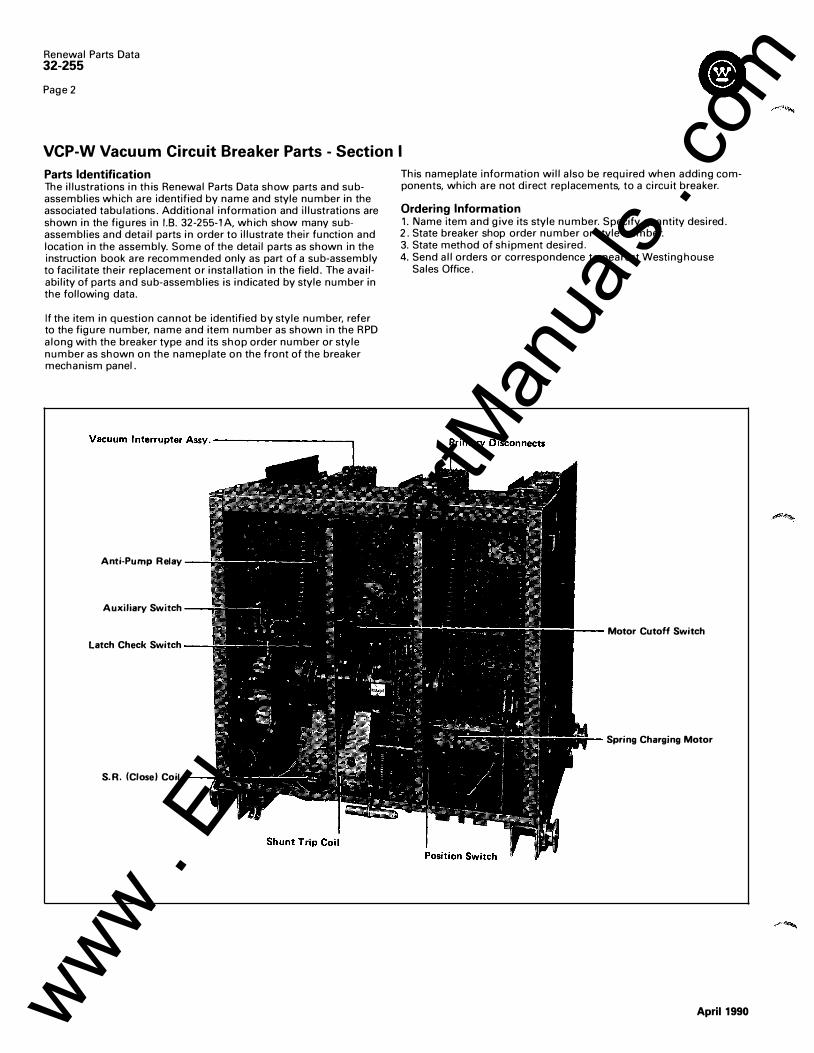
Parts Identification The illustrations in this Renewal Parts Data show parts and subassemblies which are identified by name and style number in the associated tabulations. Additional information and illustrations are shown in the figures in 1.8. 32-255-1A. which show many subassemblies and detail parts in order to illustrate their function and location in the assembly. Some of the detail parts as shown in the instruction book are recommended only as part of a sub-assembly to facilitate their replacement or installation in the field. The availability of parts and sub-assemblies is indicated by style number in the following data.
If the item in question cannot be identified by style number, refer to the figure number, name and item number as shown in the RPD along with the breaker type and its shop order number or style number as shown on the nameplate on the front of the breaker mechanism panel.
Anti-Pump Relay
Auxiliary Switch
latch Check Switch
S.R. (Close) Coil
This nameplate information will also be required when adding components, which are not direct replacements, to a circuit breaker.
Ordering Information 1. Name item and give its style number. Specify quantity desired. 2. State breaker shop order number or style number. 3. State method of shipment desired . 4. Send all orders or correspondence to nearest Westinghouse
Sales Office.
Motor Cutoff Switch
Spring Charging Motor
April1990 www . El
ectric
alPar
tMan
uals
. com
Breaker - Renewal Parts
line Description No.
01 02 03 04
05 06
07 08
09
10 11
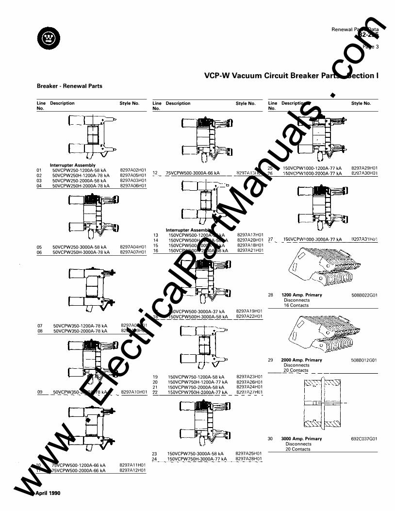
Interrupter Assembly 50VCPW250-1200A-58 kA 50VCPW250H-1200A-78 kA 50VCPW250-2000A-58 kA 50VCPW250H-2000A-78 kA
50VCPW250-3000A-58 kA 50VCPW250H-3000A-78 kA
50VCPW350-1200A-78 kA 50VCPW350-2000A-78 kA
50VCPW350-3000A-78 kA
75VCPW500-1200A-66 kA 75VCPW500-2000A-66 kA
April1990
Style No.
8297A02H01 8297A05H01 8297A03H01 8297A06H01
8297A04H01 8297A07H01
8297A08H01 8297A09H01
Renewal Parts Data 32-255
Page 3
VCP-W Vacuum Circuit Breaker Parts - Section I
line Description Style No. No.
line Description Style No. No.
25 150VCPW1000-1200A-77 kA 8297A29H01 12 75VCPW500-3000A-66 kA 8297A13H01 26 150VCPW1000-2000A-77 kA 8297A30H01 �--�������������
8297A17H01 13 14 15 16
Interrupter Assembly 150VCPW500-1200A-37 kA 150VCPW500H-1200A-58 kA 150VCPW500-2000A-37 kA 150VCPW500H-2000A-58 kA
8297 A20HO 1 ::.2:.... 7 _ _.:.:15:.:0:..:. V..::: C:_PW.:.:_: 1_::00�0� -3� 0�0..::: 0A� -..:. 7_:_ 7�k�A'--�82::::9:..:_ 7:.: A:::.31:..:_H.:_: 0:..:_1
8297A18H01 8297A21 H01
17 150VCPW500-3000A-37 kA 8297A19H01 18 150VCPW500H-3000A-58 kA 8297A22H01
19 150VCPW750-1200A-58 kA 8297A23H01 20 150VCPW750H-1200A-77 kA 8297 A26H01 21 150VCPW750-2000A-58 kA 8297A24H01
28 1200 Amp. Primary Disconnects 16 Contacts
29 2000 Amp. Primary Disconnects 20 Contacts
508B022G01
508B012G01
8297 A 1 OHO 1 ::.22�_ 1.:.: 5:.:0:..:. V..:::C:._PW:.:...:_ 7:::50::.:.H.:..·::: 20�0� 0:...:A:...:-7:..:.7...::k::.A:._� 82::::9:..:_ 7:.:A=.27:..:_ H.:.: 0:..:_ 1
8297A11 H01 8297A12H01
23 150VCPW750-3000A-58 kA 8297A25H01 24 150VCPW750H-3000A-77 kA 8297A28H01
30 3000 Amp. Primary Disconnects 20 Contacts
692C037G01
www . El
ectric
alPar
tMan
uals
. com
Renewal Parts Data 32-255
Page 4
VCP-W Vacuum Circuit Breaker Parts - Section I
Line Description No.
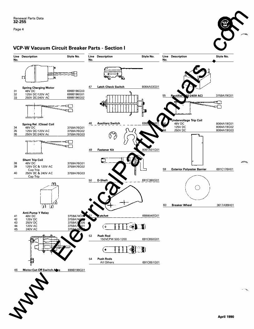
Spring Charging Motor 31 48V DC 32 125V DC/120V AC 33 250V DC/240V AC
34 35 36
38 39
40
Spring Rei. (Close) Coil 48V D C 125V DC/120V A C 250V DC/240V Ac
Shunt Trip Coil 48V DC 125V DC & 120V AC
Cap Trip 250V DC & 240V A C
Cap Trip
Anti-Pump Y Relay 41 48V DC 42 125V DC 43 250V DC 44 120V AC 45 240V AC
46 Motor Cut-Off Switch Assy.
Style No.
6998196G03 6998196G01 699B196G02
3759A76G01 3759A76G02 3759A76G03
3759A76G01 3759A76G02
3759A76G03
Line Description No.
47 Latch Check Switch
48 Auxiliary Switch
49 Fastener Kit
50 D-Shaft
Style No. Line Description No.
Style No.
8064A03G01
55
6988822H01 56
8061A01G01
691C380G01
57 58
59
60
Rectifier (120/240V ACI 3759A79G01
0 Undervoltage Trip Coil
48V DC 125V DC 250V DC
Exterior Polyester Barrier
Breaker Wheel
8064A19G01 8064A19G02 8064A19G03
691C176H01
3617A99H01
3759A74G03 ::.5-'-1 --"H:..::a:.: t::.:ch:..::e:.:t ________ _::_69:c 9:..: 8:..: 0c.:4.;_ 0G.=..::...:.01
3759A74G04 3759A74G05 3759A74G01 3759A74G02
6998199G01
�--·.:.() 53 Push Rod
150VCPW 500-1200
54 Push Rods All Others
691C650G01
691C651G01
April1990 www . El
ectric
alPar
tMan
uals
. com
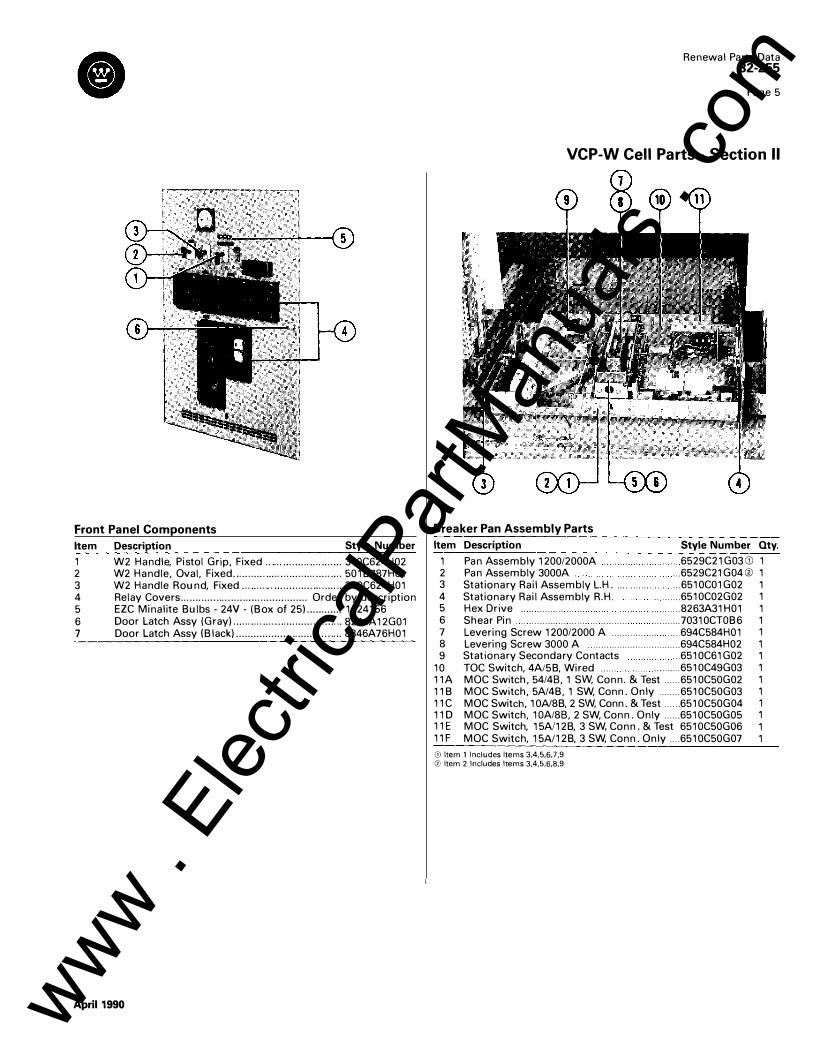
Front Panel Components
Item Description Style Number
1 W2 Handle, Pistol Grip , Fixed ........ ..... .... .... .... . 310C624H02 2 W2 Handle , Oval , Fixed ..... ..... .... ... ..... .... ..... .... .. 501 B787H01 3 W2 Handle Round, Fixed . .... ......... .... ..... ... ..... ... 31 OC624H01 4 Relay Covers . . . .. . . .. . . . . . . . . . . . . . . . .. . . .. . . .. . . . .. . ... Order by description 5 EZC Minalite Bulbs - 24V - (Box of 25) ............ 1124156 6 Door Latch Assy (Gray) ... .... ..... ......... ..... .... ....... 8244A 12G01 7 Door Latch Assy (Black) .................................... 8346A76H01
April1990
Renewal Parts Data 32-255
Page 5
VCP-W Cell Parts - Section II
Breaker Pan Assembly Parts
Item Description Style Number Qty.
1 Pan Assembly 1200/2000A .. .. 6529C21G03G) 1 2 Pan Assembly 3000A . . .. 6529C21G04® 1 3 Stationary Rail Assembly L.H. . .. 6510C01G02 1 4 Stationary Rail Assembly R.H. . . ....... 6510C02G02 1 5 Hex Drive ..... ... ... ... . ..... 8263A31H01 1 6 Shear Pin . . ........ ... ... ... ... .......... . ......... 70310CTOB6 1 7 Levering Screw 1200/2000 A ............. ... . .... 694C584H01 1 8 Levering Screw 3000 A ........................... .... 694C584H02 1 9 Stationary Secondary Contacts ... 6510C61G02 1
10 T OC Switch, 4AI5B, Wired ...... . ......... 6510C49G03 1 11A MOC Switch , 54/48, 1 SW, Conn. & Test ...... 6510C50G02 1 11 B MOC Switch , 5AI4B , 1 SW, Conn. Only ........ 6510C50G03 1 11C MOC Switch, 10AI8B, 2 SW, Conn. & Test ...... 6510C50G04 1 11 D MOC Switch , 1 OA/88, 2 SW, Conn. Only ...... 6510C50G05 1 11 E MOC Switch, 15A/12B, 3 SW, Conn. & Test 6510C50G06 1 11F MOC Switch, 15A/12B, 3 SW, Conn. Only .... 6510C50G07 1
Gl Item 1 Includes Items 3.4.5,6,7,9 @ Item 2 Includes Items 3.4,5,6,8,9
www . El
ectric
alPar
tMan
uals
. com
Renewal Parts Data 32-255
Page 6
VCP-W Cell Parts - Section II
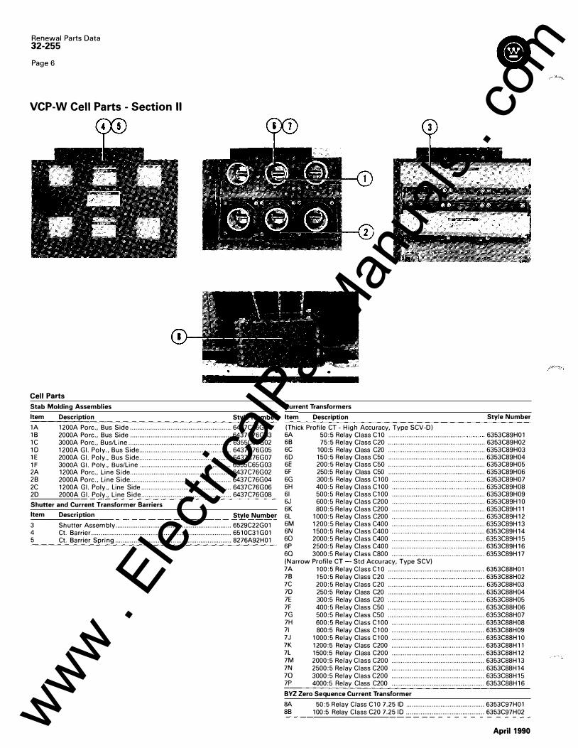
Cell Parts
Stab Molding Assemblies
Item Description Style Number
1A 1200A Pore., Bus Side ....................................................... 6437C76G01 1B 2000A Pore., Bus Side ....................................................... 6437C76G03 1 C 3000A Pore., Bus/Line ........................................................ 6355C65G02 10 1200A Gl. Poly., Bus Side .................................................. 6437C76G05 1E 2000A Gl. Poly., Bus Side .................................................. 6437C76G07 1 F 3000A Gl. Poly., Bus/Line .................................................. 6355C65G03 2A 1200A Pore., Line Side ....................................................... 6437C76G02 2B 2000A Pore., Line Side ....................................................... 6437C76G04 2C 1200A Gl. Poly., Line Side ................................................. 6437C76G06 2D 2000A Gl. Poly., Line Side ................................................. 6437C76G08
Shutter and Current T ransformer Barriers
Item Description Style Number
3 Shutter Assembly ............................................................... 6529C22G01 4 Ct. Barrier ................................. . . ............. ............................ 6510C31G01 5 Ct. Barrier Spring ............................................................... 8276A92H01
Current Transformers
Item Description Style Number
(Thick Profile CT - High Accuracy, Type SCV-D) 6A 50:5 Relay Class C10 ......................................... 6353C89H01 6B 75:5 Relay Class C20 ..................................................... 6353C89H02 6C 100:5 Relay Class C20 ..................................................... 6353C89H03 6D 150:5 Relay Class C50 ..................................................... 6353C89H04 6E 200:5 Relay Class C50 ..................................................... 6353C89H05 6F 250:5 Relay Class C50 ..................................................... 6353C89H06 6G 300:5 Relay Class C100 ................................................... 6353C89H07 6H 400:5 Relay Class C1 00 ................................................... 6353C89H08 61 500:5 Relay Class C1 00 ................................................... 6353C89H09 6J 600:5 Relay Class C200 ................................................... 6353C89H10 6K 800:5 Relay Class C200 ................................................... 6353C89H11 6L 1000:5 Relay Class C200 ................................................... 6353C89H12 6M 1200:5 Relay Class C400 ................................................... 6353C89H13 6N 1500:5 Relay Class C400 ................................................... 6353C89H14 60 2000:5 Relay Class C400 ................................................... 6353C89H15 6P 2500:5 Relay Class C400 ................................................... 6353C89H16 60 3000:5 Relay Class C800 ................................................... 6353C89H17 (Narrow Profile CT- Std Accuracy, Type SCV) 7A 100:5 Relay Class C1 0 ..................................................... 6353C88H01 7B 150:5 Relay Class C20 ..................................................... 6353C88H02 7C 200:5 Relay Class C20 ..................................................... 6353C88H03 70 250:5 Relay Class C20 ..................................................... 6353C88H04 7E 300:5 Relay Class C20 ..................................................... 6353C88H05 7F 400:5 Relay Class C50 ..................................................... 6353C88H06 7G 500:5 Relay Class C50 ..................................................... 6353C88H07 7H 600:5 Relay Class C100 ................................................... 6353C88H08 71 800:5 Relay Class C1 00 ................................................... 6353C88H09 7J 1000:5 Relay Class C100 ................................................... 6353C88H10 7K 1200:5 Relay Class C200 ................................................... 6353C88H11 7L 1500:5 Relay Class C200 ................................................... 6353C88H12 7M 2000:5 Relay Class C200 ................................................... 6353C88H13 7N 2500:5 Relay Class C200 ................................................... 6353C88H14 70 3000:5 Relay Class C200 ................................................... 6353C88H15 7P 4000:5 Relay Class C200 ................................................... 6353C88H16
BYZ Zero Sequence Current Transformer
8A 50:5 Relay Class C10 7.25 ID ........................................... 6353C97H01 8B 100:5 Relay Class C20 7.25 10 ........................................... 6353C97H02
April 1990 www . El
ectric
alPar
tMan
uals
. com
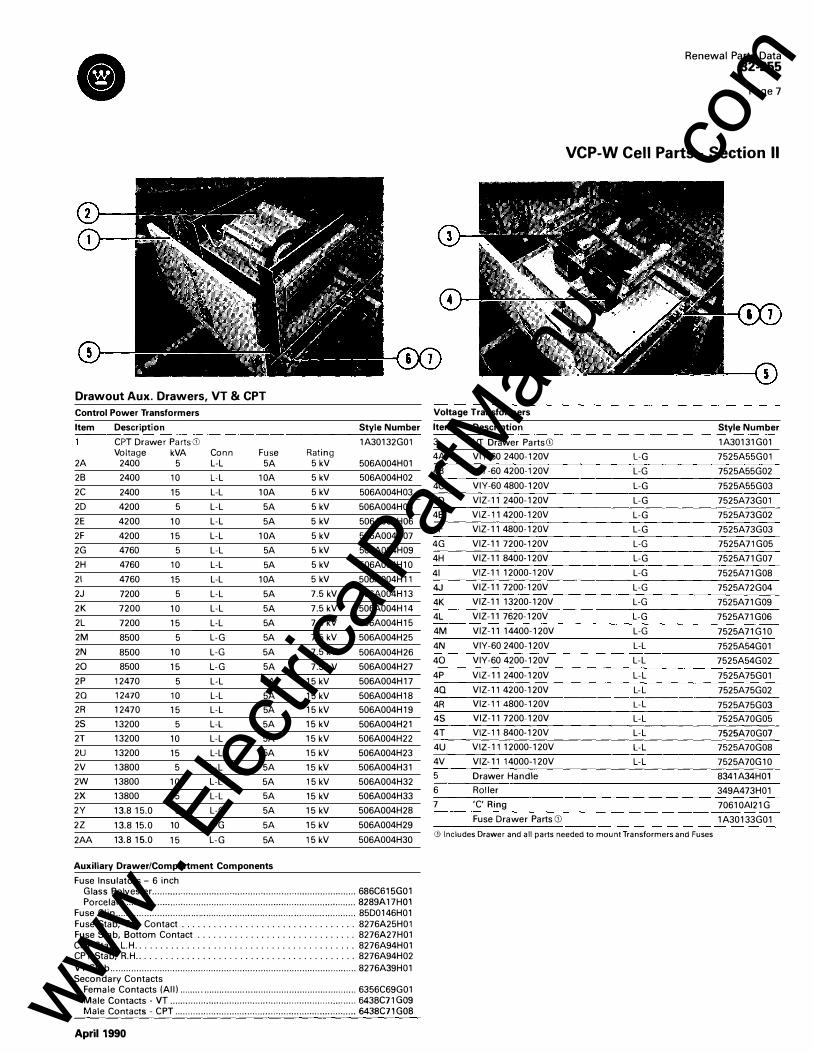
Drawout Aux. Drawers, VT & CPT
Control Power Transformers
Item Description Style Number
CP T Drawer PartsGJ 1A30132G01 Voltage kVA Conn Fuse Rating
2A 2400 5 L-L 5A 5 kV 506A004H01
28 2400 10 L-L 10A 5 kV 506A004H02
2C 2400 15 L-L 10A 5 kV 506A004H03
2D 4200 5 L-L 5A 5 kV 506A004H05
2E 4200 10 L-L 5A 5 kV 506A004H06
2F 4200 15 L-L 10A 5 kV 506A004H07
2G 4760 5 L-L 5A 5 kV 506A004H09
2H 4760 10 L-L 5A 5 kV 506A004H10
21 4760 15 L-L 10A 5 kV 506A004H11
2J 7200 5 L-L 5A 7.5 kV 506A004H13
2K 7200 10 L-L 5A 7.5 kV 506A004H14
2L 7200 15 L-L 5A 7.5 kV 506A004H15
2M 8500 5 L-G 5A 7.5 kV 506A004H25
2N 8500 10 L-G 5A 7.5 kV 506A004H26
20 8500 15 L-G 5A 7.5 kV 506A004H27
2P 12470 5 L-L 5A 15 kV 506A004H17
20 12470 10 L-L 5A 15 kV 506A004H18
2R 12470 15 L-L 5A 15 kV 506A004H19
2S 13200 5 L-L 5A 15 kV 506A004H21
2T 13200 10 L-L 5A 15 kV 506A004H22
2U 13200 15 L-L 5A 15 kV 506A004H23
2V 13800 5 L-L 5A 15 kV 506A004H31
2W 13800 10 L-L 5A 15 kV 506A004H32
2X 13800 15 L-L 5A 15 kV 506A004H33
2Y 13.8 15.0 5 L-G 5A 15 kV 506A004H28
2Z 13.8 15.0 10 L-G 5A 15 kV 506A004H29
2AA 13.8 15.0 15 L-G 5A 15 kV 506A004H30
Auxiliary Drawer/Compartment Components
Fuse Insulators- 6 inch
����:l:i�y-����-�::::::::::::::::::::::::::::::::::::::::::::::::::::::::::::::::::::::::::::::: ����!�;��� Fuse Clip ............................................................................................. 85D0146H01 Fuse Stab, Top Contact . . . . . . . . . . . . . . . . . . . . . . . . . . . . . . . . . 8276A25H01 Fuse Stab, Bottom Contact . . . . . . . . . . . . . . . . . . . . . . . . . . . . . . 8276A27H01 CPT Stab, L.H . . . . . . . . . . . . . . . . . . . . . . . . . . . . . . . . . . . . . . . . . . 8276A94H01 CPT Stab, R.H .. . . . . . . . . . . . . . . . . . . . . . . . . . . . . . . . . . . . . . . . . 8276A94H02
VT Stab ............................................................................................... 8276A39H01 Secondary Contacts
Female Contacts (All) .................................................................... 6356C69G01
�::: g���:��: : gr·:::::::::::::::::::::::::::::::::::::::::::::::::::::::::::::::::::::: �:;�g� g��
April1990
Voltage T ransformers
Item Description
3 VT Drawer PartsGJ
4A V IY-60 2400-120V
48 VIY -60 4200-120V
4C V IY -60 4800-120V
4D V IZ-11 2400-120V
4E VIZ-11 4200-120V
4F VIZ-11 4800-120V
4G V IZ-11 7200-120V
4H V IZ-11 8400-120V
41 VIZ-11 12000-120V
4J V IZ-11 7200-120V
4K V IZ-11 13200-120V
4L V IZ-11 7620-120V
4M V IZ-11 14400-120V
4N V IY-60 2400-120V
40 V IY-60 4200-120V
4P VIZ-11 2400-120V
40 V IZ-11 4200-120V
4R V IZ-11 4800-120V
4S V IZ-11 7200-120V
4T VIZ-11 8400-120V
4U VIZ-11 12000-120V
4V V IZ-11 14000-120V
5 Drawer Handle
6 Roller
7 'C' Ring
Fuse Drawer Parts Gl
Renewal Parts Data 32-255
Page 7
VCP-W Cell Parts - Section II
Style Number
1A30131G01
L-G 7525A55G01
L-G 7525A55G02
L-G 7525A55G03
L-G 7525A73G01
L-G 7525A73G02
L-G 7525A73G03
L-G 7525A71G05
L-G 7525A71G07
L-G 7525A71G08
L-G 7525A72G04
L-G 7525A71G09
L-G 7525A71G06
L-G 7525A71G10
L-L 7525A54G01
L-L 7525A54G02
L-L 7525A75G01
L-L 7525A75G02
L-L 7525A75G03
L-L 7525A70G05
L-L 7525A70G07
L-L 7525A70G08
L-L 7525A70G10
8341A34H01
349A473H01
70610AI21G
1A30133G01
CD Includes Drawer and all parts needed to mount Transformers and Fuses
www . El
ectric
alPar
tMan
uals
. com
Renewal Parts Data 32-255
Page 8
VCP-W Cell Parts - Section II
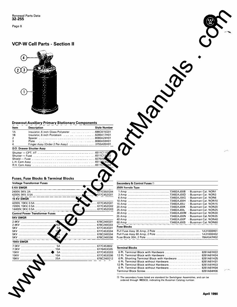
Drawout Auxiliary Primary Stationary Components
Item
1A 1B 2 3 4
Description
Insulator, 6 inch Glass Polyester Insulator, 6 inch Porcelain Spacer . Plate . Finger Assy (Order 2 Per Assy)
D.O. Drawer Shutter Assy
Shutter- CPT, VT .. Shutter- Fuse . Shield- Fuse . L.H. Cam Assy . R.H. Cam Assy
Fuses, Fuse Blocks & Terminal Blocks
Voltage Transformer Fuses
5 KV SWGR
Style Number
..... 686C615G01
..... 8289A17H01
..... 8080A24H01 ..... 8080A59H01 ..... 3755A05H01
..... 6511C11G02
. .... 6511C12G02
. .... 8276A86G01
. .... 6511C13G01 .... 6511C13G02
2400V, 5KV, 2A ...................................... . . . . . . . . . . . . . . . . . . . ..... . . . . . . . . . . . . . . . ..... . . . . . 677C592G04 4200V, 5KV, 0.5A .................................................................................... 677C452G01
15 KV SWGR
4200V, 15KV, 0.5A .................................................................................. 677C452G01 7200V, 15KV, 0.5A .................................................................................. 677C452G02 14400V, 5KV, 0.5A .................................................................................. 677C452G03
Control Power Transformer Fuses
5KV SWGR
2.4KV ............................................. 15A ................................... ........... 678C240G01 2.4KV ............................................. 25A ............................................... 678C240G03 5KV ................................................ 5A ............................................... 677C453G01 5KV ................................................ 10A ............................................... 677C453G04 5KV ................................................ 15A ............................................... 678C240G04 5KV ................................................ 25A ............................................... 678C240G06
15KV SWGR
7.5KV ............................................. 5A ............................................... 677C453602 7.5KV ............................................. 10A ............................................... 6776453G05 15KV .............................................. 5A ............................................... 677C453G03 15KV .............................................. 10A ............................................... 677C453G06 15K V . . ..... . . .. . . . . . . . . . ..... . . . . . . ........... . . .. 25A ............................................... 678C240G12
Secondary & Control Fuses CD 250V Ferrule Type
1 Amp ................................... ................... 73482AJOOB - Bussman Cat. NON1 3 Amp ....................................................... 73482AJOOD - Bussman Cat. NON3 6 Amp ....................................................... 73482AJOOG - Bussman Cat. NON6
10 Amp ....................................................... 73482AJOOH - Bussman Cat. NON10 15 Amp ....................................................... 73482AJOOJ -Bussman Cat. NON15 20 Amp ....................................................... 73482AJOOK -Bussman Cat. NON20 25 Amp ....................................................... 73482AJOOL - Bussman Cat. NON25 30 Amp ....................................................... 73482AJOOM - Bussman Cat. NON30 35 Amp . . . . . . . . . . . . . . . . . . . . . . . . . . . 73482AJOON - Bussman Cat. NON35 40 Amp ....................................................... 73482AJOOP - Bussman Cat. NON40 60 Amp ....................................................... 73482AJOOS - Bussman Cat. NON60
Fuse Blocks
Pull Fuse Assy 30 Amp, 2 Pole . . . . . . .......... . . . ........ . . . . . . . . . . ... . . ................. 1A31000H01 Pull Fuse Assy 60 Amp, 2 Pole ..................................................... 1A31000H02 Fuse Block 30A, 2 Pole . . . . . . . . . . . . . . . .......... . . . . . . . ........ . . . . . .. . . . . . . . . .................. 784A547H02
Terminal Blocks
6 Pt. Terminal Block with Hardware . .. . .. . . . .. . . . .. . . . . . . . 8261A61H22 12 Pt. Terminal Block with Hardware . . . . . . ................. 8261A61 H24
6 Pt. Shorting Terminal Block with Hardware .. . .. . . . .. . .. . . 8261A61 H25 6 Pt. Terminal Block without Hardware . . . . . . . . . . . . . . . . . . . . . 8261A61H31
12 Pt. Terminal Block without Hardware . . . . . . . . . . . . . . . . . . . . . 8261A61H33 6 Pt. Terminal Block without Hardware . . . . .. . . . . . . . . . . . .. . . 8261A61H34
Terminal Block Screw . . . . . . . . . . . . . . . . . . . . . . . . . . . . . . . . . . . . 8261A64H06
CD The secondary fuses listed are standard for Switchgear Assemblies, and can be ordered through WESCO, indicating the Bussman Catalog number.
April1990 www . El
ectric
alPar
tMan
uals
. com
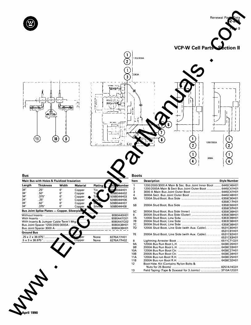
Bus
Main Bus with Holes & Fluidized Insulation
Length Thickness Width Material Plating Style Number
34" .25" 6" Copper Tin 509B044H01 34" .50" 6" Copper Tin 509B044H02 34" .375" 6" Copper Tin 509B044H03 34" .25" 6" Copper Silver 509B044H06 34" .50" 6" Copper Silver 509B044H07 34" .375" 6" Copper Silver 509B044H08
Bus Joint Splice Plates- Copper, Silverplated
Without I nserts - ................................................................................... 8080A40H01 With Inserts - . . . . . . . .. . . . ..... .................... . . . . . . . . . . . ..................... .................... 8080A47G01 With I nserts & Jumper Cable Term'l Mtg. - ....................................... 8080A47G02 Bus Joint Spacer 1200/2000/3000A- .................................................. 8080A38H01 Bus Joint Spacer 3000 A - .................................................................... 8080A39H01
Ground Bus
.25 x 2 x 38.875'.' ..................................... Copper
.5 x 3 x 38.875" ... .................................. Copper
April1990
N one None
8276A77H01 8276A77H02
Boots
Item
1 2 3 4 5A
58
5C 6 7A 78 7C 7D
7E
8 9A 98
10A 108 11A 118 12
13
Renewal Parts Data 32-255
Page 9
VCP-W Cell Parts- Section II
,� .. , 1 J (i)41
3000A
l CD
Description Style Number
1200/2000/3000 A Main & Sec. Bus Joint I nner Boot ........ 6445C46H01 1200/2000A Main & Sect Bus Joint Outer Boot .................. 6445C47H01 3000 A Main Bus Joint Outer Boot ...................................... 6445C47H01 3000A Sect. Bus Joint Outer Boot ....................................... 6445C48H01 1200A Stud Boot, Bus Side .................................................. 6359C90H01
6359C17H01 2000A Stud Boot. Bus Side .................................................. 6359C66H01
6359C97H01 3000A Stud Boot, Bus Side (I nner) ...................................... 6359C99H01 3000A Stud Boot, Bus Side (Outer) ..................................... 6359C98H01 1200A Stud Boot, Line Side .................................................. 6363C99H01 2000A Stud Boot, Line Side ................................................. 6363C98H01 3000A Stud Boot, Line Side ................................................. 6359C98H01 1200A Stud Boot, Line Side (with Aux. Cable) . . . . . . . . . 6531C80H01
6531C81H01 2000A Stud Boot, Line Side (with Aux. Cable) .. . . . .. . . 6531C82H01
6531C83H01 Lightning Arrester Boot .. . . . . . . . . . . . . . . . . . . . . . .. . . 6511C71G01 1200A Bus Run Boot L.H . ..................................................... 6438C26H01 2000A Bus Run Boot L.H . ..................................................... 6438C33H01 1200A Bus Run Boot Ctr . ...................................................... 6438C27H01 2000A Bus Run Boot Ctr . ...................................................... 6438C34H01 1200A Bus run Boot R.H . ...................................................... 6438C25H01 2000A Bus run Boot R.H . ...................................................... 6438C32H01 Boot Hdw. K it (Contains Nylon Bolts &
N uts for 25 Boots) ............................................................. 8257 A74G01 Field Taping (Tape & Duxseal for 3 Joints) ......................... 3710A12G01
www . El
ectric
alPar
tMan
uals
. com
Renewal Parts Data 32-255
Page 10
VCP-W Cell Parts - Section II
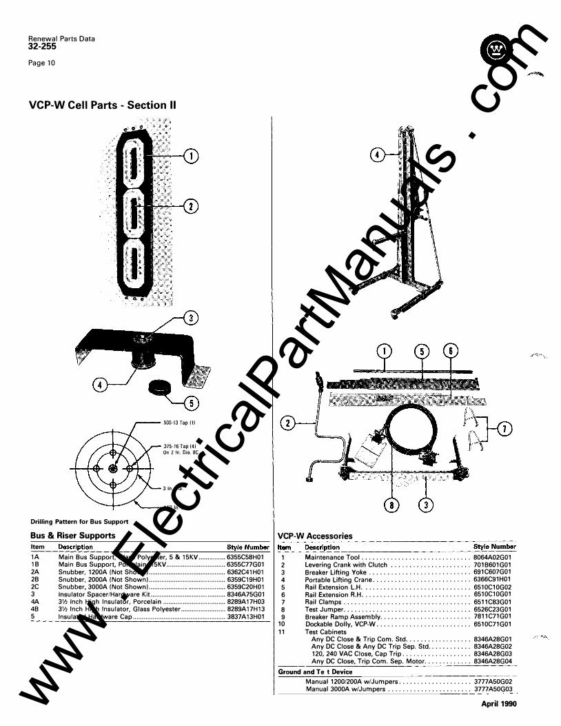
.500-1 3 Tap (1)
.375-16 Tap (41 On 2 ln. Dia. BC
3 ln. Oia.
4.50 ln. Dia.
J���.· r 1
.
Drilling Pattern for Bus Support
Bus & Riser Supports VCP-W Accessories
Item
1A 1B 2A 2B 2C 3 4A 4B 5
Description Style Number -'-ltec__m_c__c_ __ D_:_ es_c:_r_,_ ipt_i_o_n ________________ S_ty_,_ l_ e _ N_u_m_b_e_r
Main Bus Support, Glass Polyester, 5 & 15KV ...... .. ....... 6355C58H01 1 Maintenance Tool ..... . .. . ............ . . . . . . ... 8064A02G01 Main Bus Support, Porcelain, 15KV . ... .. ............. ........... ... 6355C77G01 2 levering Crank with Clutch ... ... .. .. .. ....... .. . 701B601G01 Snubber, 1200A (Not Shown) ...... ............ ................ ......... 6362C41H01 3 Breaker lifting Yoke ...... .. . ..... . .. . . .. . .. . ... 691C607G01 Snubber, 2000A (Not Shown) . ..... ............ ............. ..... ....... 6359C19H01 4 Portable lifting Crane . . ....... . . . . ..... ..... . . . . 6366C91H01 Snubber, 3000A (Not Shown) ...... ............ ............ ... .......... 6359C20H01 5 Rail Extension l.H . .. ....... . . ... . . . ...... . . . . . . 6510C10G02 Insulator Spacer/Hardware Kit ... ........ ............ .... ...... ...... ... 8346A75G01 6 Rail Extension R.H .. . ... . . . . ... . . ..... ..... . . . . . 6510C10G01 3V2 Inch High Insulator, Porcelain ....... ....... ..... ... ......... .... 8289A17H03 7 Rail Clamps .... .. .. . .. ... . . ... . . .. .. .. . .... ... 6511C83G01 3% Inch High Insulator, Glass Polyester ........ ...... ...... ... .. 8289A17H13 8 Test Jumper ... . . .. . . . . .. ... ... . . .. .. .. . . .. . ... 6526C23G01 Insulated Hardware Cap .................................................... 3837A13H01 9 Breaker Ramp Assembly . .... .. .. . .. . .. . . .. .. . ... 7811C71G01
10 Dockable Dolly, VCP-W .... .. .. .. . ..... . .. . ... . . . 6510C71G01 11 Test Cabinets
Any DC Close & Trip Com. Std ......... .. .. . . ... 8346A28G01 Any DC Close & Any DC Trip Sep . Std . ..... ..... . 8346A28G02 120, 240 VAG Close, Cap Trip .. . .. . . . . . .. ... ... . 8346A28G03 Any DC Close, Trip Com. Sep. Motor . . . . . .. . .. . .. 8346A28G04
Grou nd and Test Devices
Manual 1200/200A w/Jumpers ..... ...... ..... . . . . 3777A50G02 Manual 3000A w/Jumpers . . . .. . . ....... .... ... .. 3777A50G03
April1990 www . El
ectric
alPar
tMan
uals
. com
April1990
Renewal Parts Data 32-255
Page 11
VCP-W Cell Parts - Section II
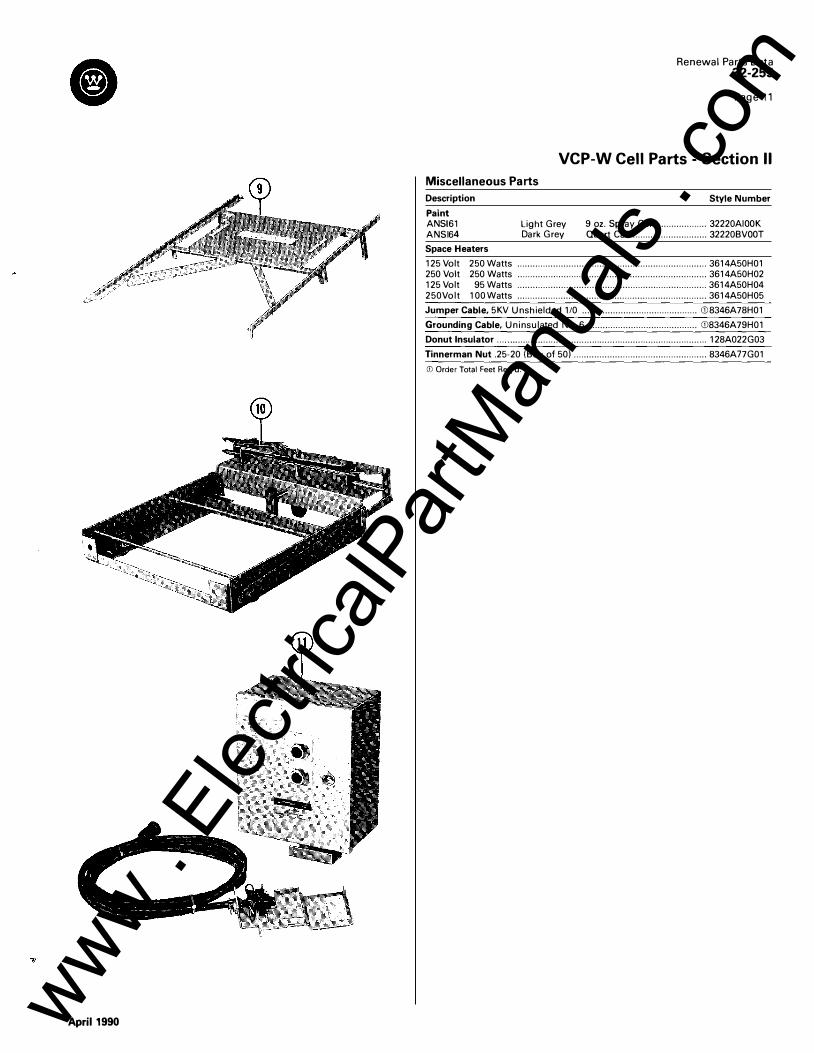
Miscellaneous Parts
Description
Paint ANSI61 ANSI64
Space Heaters
Light Grey Dark Grey
Style Number
9 oz. Spray Can .................. 32220AIOO K Quart Can ............................. 32220BVOO T
125 Volt 250 Watts .......................................................................... 3614A50H01 250 Volt 250 Watts .......................................................................... 3614A50H02 125 Volt 95 Watts .......................................................................... 3614A50H04 250Volt 100Watts .......................................................................... 3614A50H05
Jumper Cable, 5K V Unshielded 1/0 ............................................. Gl8346A78H01
Grounding Cable, Uninsulated No. 6 ........................................... Gl8346A79H01
Donut Insulator . . . . . . . . . . . . . ..... . . . . .. . . . ............ ....... . . . ....... . . ...... . . ...... . . . .... . . . 128A022G03
Tinnerman Nut .25-20 (Box of 50) .................................................... 8346A77G01
GJ Order Total Feet Req'd.
www . El
ectric
alPar
tMan
uals
. com
Renewal Parts Data 32-255
Page 12
Westinghouse Electric Corporation Distribution and Control Business Unit Commercial Operations Division Pittsburgh, Pennsylvania , U.S.A. 15220
Printed in U.S.A.
April1990 www . El
ectric
alPar
tMan
uals
. com