vacclad-w 27 kv, metal-clad medium-voltage switchgear · a the switchgear assembly is designed for...
TRANSCRIPT
Medium-voltage power distribution and control systems > Switchgear >
VacClad-W 27 kV, metal-clad medium-voltage switchgear
Contents
General Description . . . . . . . . . . . . . . . . . . . . . . . . . . . 5 .4-2Standard Metal-Clad Switchgear Assembly Ratings . 5 .4-4Unusual and Usual Service Conditions . . . . . . . . . . . 5 .4-5
Devices . . . . . . . . . . . . . . . . . . . . . . . . . . . . . . . . . . . . . 5 .4-6Circuit Breakers . . . . . . . . . . . . . . . . . . . . . . . . . . . . . 5 .4-6Protection Relays and Metering . . . . . . . . . . . . . . . . . 5 .4-10Instrument Transformers . . . . . . . . . . . . . . . . . . . . . . 5 .4-10Dummy Element (Dummy Breaker) . . . . . . . . . . . . . . 5 .4-11Integral Motorized Remote Racking Option (VC-W MR2) . . . . . . . . . . . . . . . . . . . . . . . . . . . . . . . . 5 .4-12Accessories . . . . . . . . . . . . . . . . . . . . . . . . . . . . . . . . 5 .4-16System Options . . . . . . . . . . . . . . . . . . . . . . . . . . . . . 5 .4-17
Layouts and Dimensions . . . . . . . . . . . . . . . . . . . . . . 5 .4-20Standard . . . . . . . . . . . . . . . . . . . . . . . . . . . . . . . . . . . 5 .4-20
Application Data . . . . . . . . . . . . . . . . . . . . . . . . . . . . . 5 .4-25Weights . . . . . . . . . . . . . . . . . . . . . . . . . . . . . . . . . . . 5 .4-25Control Power . . . . . . . . . . . . . . . . . . . . . . . . . . . . . . 5 .4-25Typical Schematics . . . . . . . . . . . . . . . . . . . . . . . . . . . 5 .4-26
More about this product
Eaton.com/mva
Complete library of design guides
Eaton.com/designguides
Design Guide DG022004EN Effective February 2020
General DescriptionEaton’s 27 kV nominal metal-clad switchgear is used for applications at system voltages higher than 15 kV, up to and including 27 kV. It is designed for use with Type VCP-W, horizontal drawout vacuum circuit breakers.
Ratings■ Maximum rated voltage: 27 kV rms
Note: Eaton tested to 28.5 kV.
■ BIL withstand: 125 kV peak■ Maximum symmetrical interrupting: 16 kA, 22 kA, 25 kA, 40 kA rms
■ Continuous current: Circuit breakers—1200 A, 2000 A Switchgear main bus— One-high design: 1200 A, 2000 A Two-high design: 1200 A, 2000 A, 2500 A, 2700 A
Features and Configurations27 kV metal-clad switchgear design is an extension of Eaton’s 5 and 15 kV VacClad design. It has same footprint and overall space envelop, and it incorporates all features and advantages of the 5 and 15 kV VacClad design, with the exception of some modifications required for 27 kV application.
■ Uses horizontal drawout type VCP-W 125 kV BIL rated vacuum circuit breakers
■ A cycloaliphatic epoxy insulation material is used throughout the switchgear housings and the circuit breakers for phase-to-ground and phase-to-phase primary bus supports. For decades, cycloaliphatic epoxy insulation has demonstrated its outstanding electrical and mechanical characteristics in harsh outdoor applications. The use of this insulation system with the 27 kV design ensures a comfortable margin of safety at higher voltages
■ All primary bus conductors are insulated for full 28.5 kV by fluidized epoxy coating. All buses are fabricated from 100% conductivity copper. Bus joints are silver- or tin-plated as required, and covered with pre-formed insulating boots to maintain metal-clad integrity
■ Available configurations include: auxiliary over breaker, and auxiliary over auxiliary. Each auxiliary or breaker requires one-half vertical space
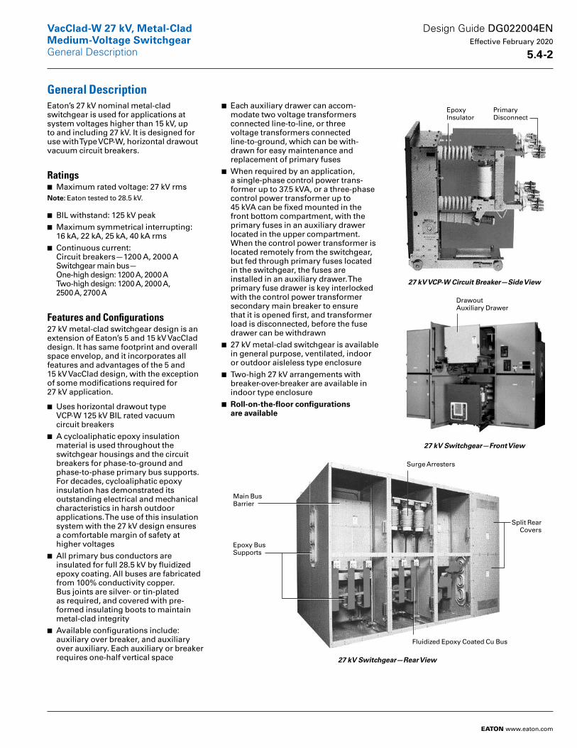
■ Each auxiliary drawer can accom-modate two voltage transformers connected line-to-line, or three voltage transformers connected line-to-ground, which can be with-drawn for easy maintenance and replacement of primary fuses
■ When required by an application, a single-phase control power trans-former up to 37.5 kVA, or a three-phase control power transformer up to 45 kVA can be fixed mounted in the front bottom compartment, with the primary fuses in an auxiliary drawer located in the upper compartment. When the control power transformer is located remotely from the switchgear, but fed through primary fuses located in the switchgear, the fuses are installed in an auxiliary drawer. The primary fuse drawer is key interlocked with the control power transformer secondary main breaker to ensure that it is opened first, and transformer load is disconnected, before the fuse drawer can be withdrawn
■ 27 kV metal-clad switchgear is available in general purpose, ventilated, indoor or outdoor aisleless type enclosure
■ Two-high 27 kV arrangements with breaker-over-breaker are available in indoor type enclosure
■ Roll-on-the-floor configurations are available
27 kV VCP-W Circuit Breaker—Side View
27 kV Switchgear—Front View
27 kV Switchgear—Rear View
Epoxy Insulator
Primary Disconnect
Drawout Auxiliary Drawer
Main Bus Barrier
Surge Arresters
Epoxy Bus Supports
Fluidized Epoxy Coated Cu Bus
Split Rear Covers
Design Guide DG022004EN Effective February 2020
5 .4-2
VacClad-W 27 kV, Metal-CladMedium-Voltage Switchgear
EATON www.eaton.com
General Description
AdvantagesEaton has been manufacturing metal-clad switchgear for over 60 years, and vacuum circuit breakers for more than 40 years. Tens of thousands of Eaton vacuum circuit breakers, used in a wide variety of applications, have been setting industry performance standards for years.
With reliability as a fundamental goal, Eaton engineers have simplified the VacClad-W switchgear design to mini- mize problems and gain trouble-free performance. Special attention was given to material quality and maximum possible use was made of components proven over the years in Eaton switchgear.
Maintenance requirements are minimized by the use of enclosed long-life vacuum interrupters. When maintenance or inspection is required, the component arrangements and drawers allow easy access. The light weight of the VacClad-W simplifies handling and relocation of the breakers.
StandardsEaton’s VacClad-W switchgear meets or exceeds ANSI/ IEEE C37.20.2 and NEMA® SG-5 as they apply to metal-clad switchgear. The assemblies also conform to Canadian standard CSA®-C22.2 No. 31-04, and EEMAC G8-3.2. Type VCP-W vacuum circuit breakers meet or exceed all ANSI and IEEE standards applicable to ac high-voltage circuit breakers rated on symmetrical current basis.
Metal-Clad Switchgear CompartmentalizationMedium-voltage metal-clad switchgear equipment conforming to C37.20.2 is a compartmentalized design, wherein primary conductors are fully insulated for the rated maximum voltage of the assembly, and all major primary circuit components are isolated from each other by grounded metal barriers. This type of construction minimizes the likelihood of arcing faults within the equipment and propagation of fault between the compartments containing major primary circuits.
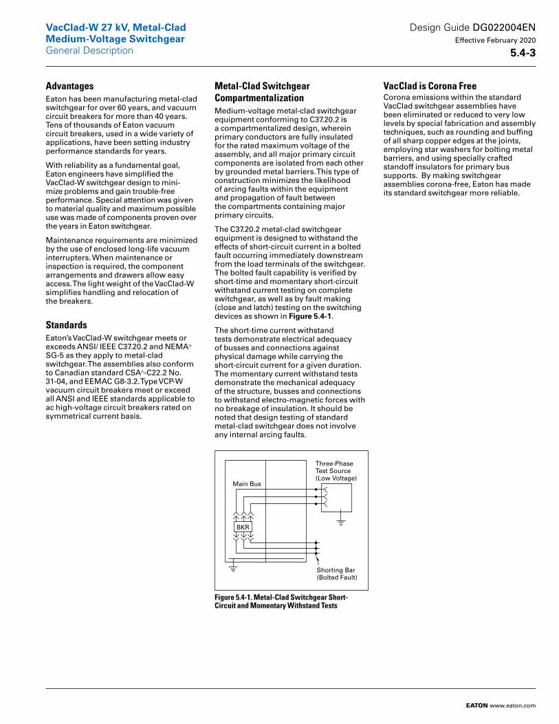
The C37.20.2 metal-clad switchgear equipment is designed to withstand the effects of short-circuit current in a bolted fault occurring immediately downstream from the load terminals of the switchgear. The bolted fault capability is verified by short-time and momentary short-circuit withstand current testing on complete switchgear, as well as by fault making (close and latch) testing on the switching devices as shown in Figure 5 .4-1.
The short-time current withstand tests demonstrate electrical adequacy of busses and connections against physical damage while carrying the short-circuit current for a given duration. The momentary current withstand tests demonstrate the mechanical ade quacy of the structure, busses and connections to withstand electro-magnetic forces with no breakage of insulation. It should be noted that design testing of standard metal-clad switchgear does not involve any internal arcing faults.
Figure 5.4-1. Metal-Clad Switchgear Short- Circuit and Momentary Withstand Tests
VacClad is Corona FreeCorona emissions within the standard VacClad switchgear assemblies have been eliminated or reduced to very low levels by special fabrication and assembly techniques, such as rounding and buffing of all sharp copper edges at the joints, employing star washers for bolting metal barriers, and using specially crafted standoff insulators for primary bus supports. By making switchgear assemblies corona-free, Eaton has made its standard switchgear more reliable.
Main Bus
BKR
Shorting Bar(Bolted Fault)
Three-Phase Test Source(Low Voltage)
Design Guide DG022004EN Effective February 2020
5 .4-3
VacClad-W 27 kV, Metal-CladMedium-Voltage SwitchgearGeneral Description
EATON www.eaton.com
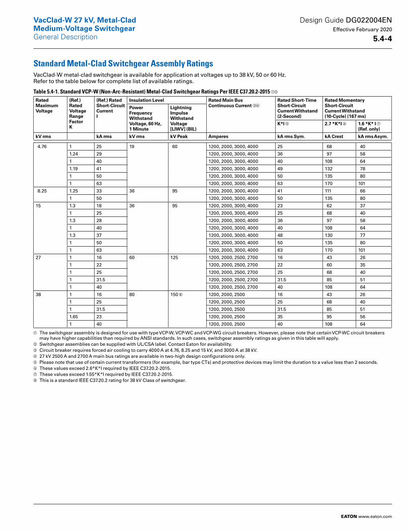
Standard Metal-Clad Switchgear Assembly RatingsVacClad-W metal-clad switchgear is available for application at voltages up to 38 kV, 50 or 60 Hz. Refer to the table below for complete list of available ratings.
Table 5.4-1. Standard VCP-W (Non-Arc-Resistant) Metal-Clad Switchgear Ratings Per IEEE C37.20.2-2015 ab
RatedMaximumVoltage
(Ref .) Rated Voltage Range Factor K
(Ref .) Rated Short-Circuit Current I
Insulation Level Rated Main BusContinuous Current cd
Rated Short-Time Short-CircuitCurrent Withstand(2-Second)
Rated Momentary Short-CircuitCurrent Withstand (10-Cycle) (167 ms)
Power Frequency Withstand Voltage, 60 Hz, 1 Minute
Lightning Impulse Withstand Voltage [LIWV] (BIL)
K*I e 2 .7 *K*I f 1 .6 *K* I g(Ref . only)
kV rms kA rms kV rms kV Peak Amperes kA rms Sym . kA Crest kA rms Asym .
4.76 1 25 19 60 1200, 2000, 3000, 4000 25 68 40
1.24 29 1200, 2000, 3000, 4000 36 97 58
1 40 1200, 2000, 3000, 4000 40 108 64
1.19 41 1200, 2000, 3000, 4000 49 132 78
1 50 1200, 2000, 3000, 4000 50 135 80
1 63 1200, 2000, 3000, 4000 63 170 101
8.25 1.25 33 36 95 1200, 2000, 3000, 4000 41 111 66
1 50 1200, 2000, 3000, 4000 50 135 80
15 1.3 18 36 95 1200, 2000, 3000, 4000 23 62 37
1 25 1200, 2000, 3000, 4000 25 68 40
1.3 28 1200, 2000, 3000, 4000 36 97 58
1 40 1200, 2000, 3000, 4000 40 108 64
1.3 37 1200, 2000, 3000, 4000 48 130 77
1 50 1200, 2000, 3000, 4000 50 135 80
1 63 1200, 2000, 3000, 4000 63 170 101
27 1 16 60 125 1200, 2000, 2500, 2700 16 43 26
1 22 1200, 2000, 2500, 2700 22 60 35
1 25 1200, 2000, 2500, 2700 25 68 40
1 31.5 1200, 2000, 2500, 2700 31.5 85 51
1 40 1200, 2000, 2500, 2700 40 108 64
38 1 16 80 150 h 1200, 2000, 2500 16 43 26
1 25 1200, 2000, 2500 25 68 40
1 31.5 1200, 2000, 2500 31.5 85 51
1.65 23 1200, 2000, 2500 35 95 56
1 40 1200, 2000, 2500 40 108 64
a The switchgear assembly is designed for use with type VCP-W, VCP-WC and VCP-WG circuit breakers. However, please note that certain VCP-WC circuit breakers may have higher capabilities than required by ANSI standards. In such cases, switchgear assembly ratings as given in this table will apply.
b Switchgear assemblies can be supplied with UL/CSA label. Contact Eaton for availability.c Circuit breaker requires forced air cooling to carry 4000 A at 4.76, 8.25 and 15 kV, and 3000 A at 38 kV.d 27 kV 2500 A and 2700 A main bus ratings are available in two-high design configurations only.e Please note that use of certain current transformers (for example, bar type CTs) and protective devices may limit the duration to a value less than 2 seconds.f These values exceed 2.6*K*I required by IEEE C37.20.2-2015.g These values exceed 1.55*K*I required by IEEE C37.20.2-2015.h This is a standard IEEE C37.20.2 rating for 38 kV Class of switchgear.
Design Guide DG022004EN Effective February 2020
5 .4-4
VacClad-W 27 kV, Metal-CladMedium-Voltage SwitchgearGeneral Description
EATON www.eaton.com
Unusual and Usual Service Conditions
Unusual Service ConditionsApplications of metal-clad switchgear at other than usual altitude or temper ature, or where solar radiation is sig nificant, require special consideration. Other unusual service conditions that may affect design and application include:
■ Exposure to salt air, hot or humid climate, excessive dust, dripping water, falling dirt, or other similar conditions
■ Unusual transportation or storage conditions
■ Switchgear assemblies when used as the service disconnecting means
■ Installations accessible to the general public
■ Exposure to seismic shock■ Exposure to nuclear radiation
Usual Service ConditionsUsual service conditions for operation of metal-clad switchgear are as follows:
■ Altitude does not exceed 3300 feet (1000 m)
■ Ambient temperature within the limits of –30 °C and +40 ºC (–22 °F and +104 °F)
■ The effect of solar radiation is not significant
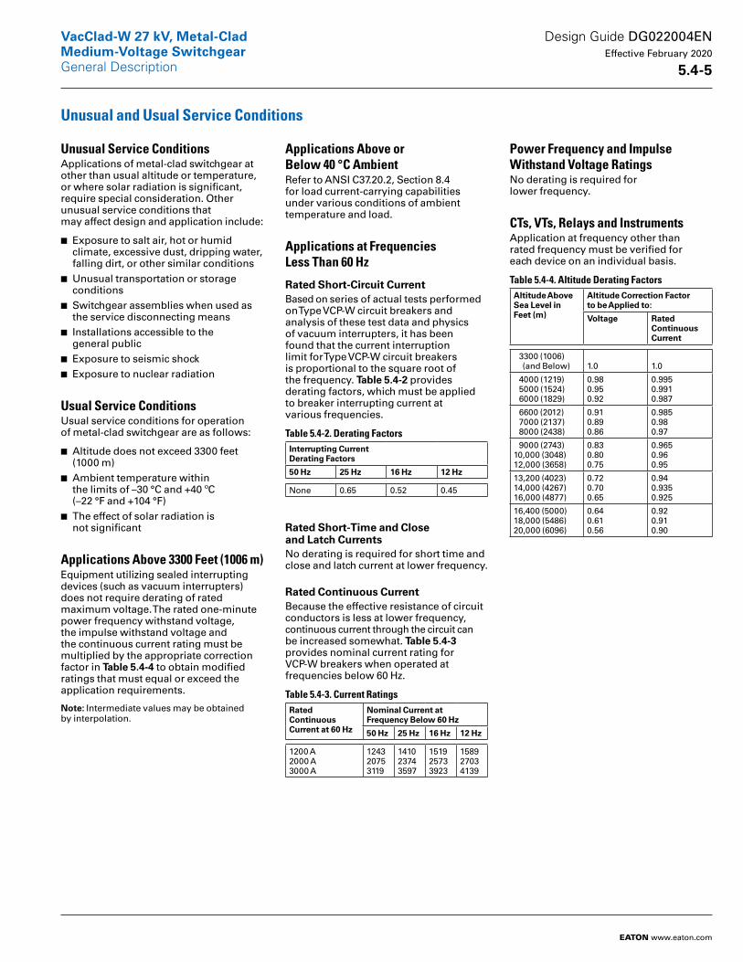
Applications Above 3300 Feet (1006 m)Equipment utilizing sealed interrupting devices (such as vacuum interrupters) does not require derating of rated maximum voltage. The rated one-minute power frequency withstand voltage, the impulse withstand voltage and the continuous current rating must be multiplied by the appropriate correction factor in Table 5 .4-4 to obtain modified ratings that must equal or exceed the application requirements.
Note: Intermediate values may be obtained by interpolation.
Applications Above or Below 40 °C AmbientRefer to ANSI C37.20.2, Section 8.4 for load current-carrying capabilities under various conditions of ambient temperature and load.
Applications at Frequencies Less Than 60 Hz
Rated Short-Circuit CurrentBased on series of actual tests performed on Type VCP-W circuit breakers and analysis of these test data and physics of vacuum interrupters, it has been found that the current interruption limit for Type VCP-W circuit breakers is proportional to the square root of the frequency. Table 5 .4-2 provides derating factors, which must be applied to breaker interrupting current at various frequencies.
Table 5.4-2. Derating Factors Interrupting CurrentDerating Factors
50 Hz 25 Hz 16 Hz 12 Hz
None 0.65 0.52 0.45
Rated Short-Time and Close and Latch CurrentsNo derating is required for short time and close and latch current at lower frequency.
Rated Continuous CurrentBecause the effective resistance of circuit conductors is less at lower frequency, continuous current through the circuit can be increased somewhat. Table 5 .4-3 provides nominal current rating for VCP-W breakers when operated at frequencies below 60 Hz.
Table 5.4-3. Current Ratings Rated Continuous Current at 60 Hz
Nominal Current at Frequency Below 60 Hz
50 Hz 25 Hz 16 Hz 12 Hz
1200 A2000 A3000 A
124320753119
141023743597
151925733923
158927034139
Power Frequency and Impulse Withstand Voltage RatingsNo derating is required for lower frequency.
CTs, VTs, Relays and InstrumentsApplication at frequency other than rated frequency must be verified for each device on an individual basis.
Table 5.4-4. Altitude Derating Factors Altitude AboveSea Level inFeet (m)
Altitude Correction Factor to be Applied to:
Voltage Rated ContinuousCurrent
3300 (1006) (and Below) 1.0 1.0
4000 (1219) 5000 (1524) 6000 (1829)
0.980.950.92
0.9950.9910.987
6600 (2012) 7000 (2137) 8000 (2438)
0.910.890.86
0.9850.980.97
9000 (2743)10,000 (3048)12,000 (3658)
0.830.800.75
0.9650.960.95
13,200 (4023)14,000 (4267)16,000 (4877)
0.720.700.65
0.94 0.9350.925
16,400 (5000)18,000 (5486)20,000 (6096)
0.640.610.56
0.920.910.90
Design Guide DG022004EN Effective February 2020
5 .4-5
VacClad-W 27 kV, Metal-CladMedium-Voltage SwitchgearGeneral Description
EATON www.eaton.com
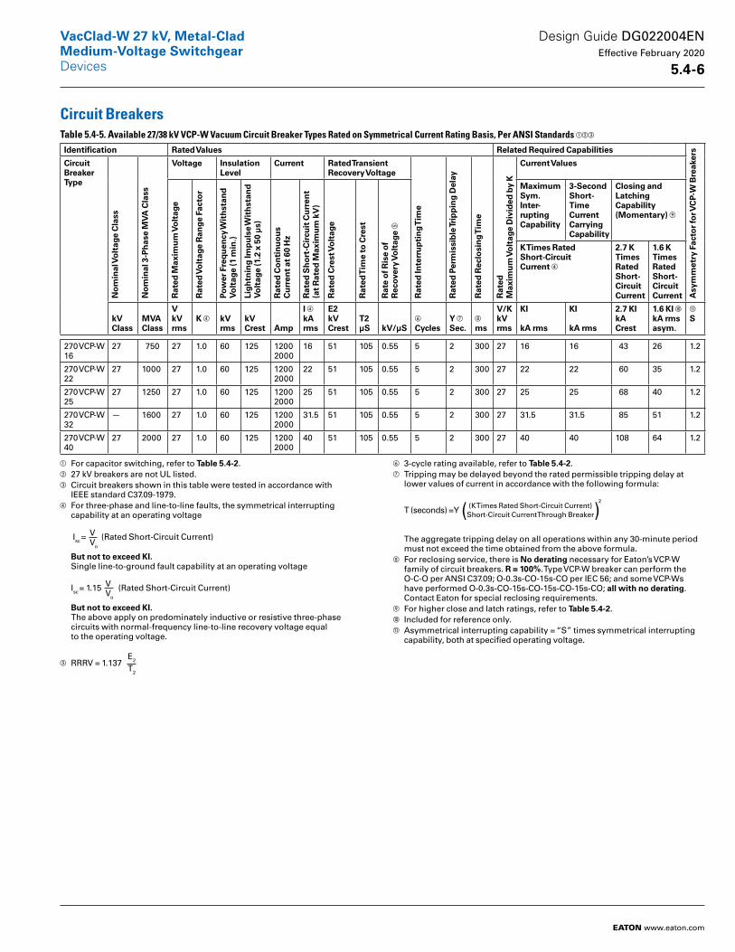
Circuit BreakersTable 5.4-5. Available 27/38 kV VCP-W Vacuum Circuit Breaker Types Rated on Symmetrical Current Rating Basis, Per ANSI Standards abc
Identification Rated Values Related Required Capabilities
Asy
mm
etry
Fac
tor
for V
CP-
W B
reak
ers
Circuit Breaker Type
No
min
al V
olt
age
Cla
ss
No
min
al 3
-Ph
ase
MV
A C
lass
Voltage Insulation Level
Current Rated TransientRecovery Voltage
Rat
ed In
terr
up
tin
g T
ime
Rat
ed P
erm
issi
ble
Trip
pin
g D
elay
Rat
ed R
eclo
sin
g T
ime
Rat
ed
Max
imu
m V
olt
age
Div
ided
by
K
Current ValuesR
ated
Max
imu
m V
olt
age
Rat
ed V
olt
age
Ran
ge F
acto
r
Pow
er F
req
uen
cy W
ith
stan
d
Vo
ltag
e (1
min
.)
Lig
htn
ing
Imp
uls
e W
ith
stan
d
Vo
ltag
e (1
.2 x
50
µs)
Rat
ed C
on
tin
uo
us
C
urr
ent
at 6
0 H
z
Rat
ed S
ho
rt-C
ircu
it C
urr
ent
(at
Rat
ed M
axim
um
kV
)
Rat
ed C
rest
Vo
ltag
e
Rat
ed T
ime
to C
rest
Rat
e o
f Ris
e o
f R
ecov
ery
Vo
ltag
e e
MaximumSym .Inter-ruptingCapability
3-Second Short-Time Current Carrying Capability
Closing and LatchingCapability (Momentary) i
K Times Rated Short-Circuit Current d
2 .7 K TimesRated Short- Circuit Current
1 .6 K TimesRated Short- Circuit Current
kVClass
MVAClass
VkV rms
K d kV rms
kV Crest Amp
I dkA rms
E2kV Crest
T2µS kV/µS
f
CyclesY gSec .
h
ms
V/KkV rms
KI
kA rms
KI
kA rms
2 .7 KIkA Crest
1 .6 KI jkA rms asym .
k
S
270 VCP-W16
27 750 27 1.0 60 125 12002000
16 51 105 0.55 5 2 300 27 16 16 43 26 1.2
270 VCP-W22
27 1000 27 1.0 60 125 12002000
22 51 105 0.55 5 2 300 27 22 22 60 35 1.2
270 VCP-W25
27 1250 27 1.0 60 125 12002000
25 51 105 0.55 5 2 300 27 25 25 68 40 1.2
270 VCP-W 32
— 1600 27 1.0 60 125 12002000
31.5 51 105 0.55 5 2 300 27 31.5 31.5 85 51 1.2
270 VCP-W 40
27 2000 27 1.0 60 125 12002000
40 51 105 0.55 5 2 300 27 40 40 108 64 1.2
a For capacitor switching, refer to Table 5 .4-2.b 27 kV breakers are not UL listed.c Circuit breakers shown in this table were tested in accordance with
IEEE standard C37.09-1979.d For three-phase and line-to-line faults, the symmetrical interrupting
capability at an operating voltage Isc = V
Vo
(Rated Short-Circuit Current) But not to exceed KI . Single line-to-ground fault capability at an operating voltage Isc = 1.15 V
Vo
(Rated Short-Circuit Current) But not to exceed KI . The above apply on predominately inductive or resistive three-phase circuits with normal-frequency line-to-line recovery voltage equal to the operating voltage.
e RRRV = 1.137 E2
T2
f 3-cycle rating available, refer to Table 5 .4-2.g Tripping may be delayed beyond the rated permissible tripping delay at
lower values of current in accordance with the following formula:
T (seconds) = Y (K Times Rated Short-Circuit Current)Short-Circuit Current Through Breaker( )
2
The aggregate tripping delay on all operations within any 30-minute period must not exceed the time obtained from the above formula.
h For reclosing service, there is No derating necessary for Eaton’s VCP-W family of circuit breakers. R = 100%. Type VCP-W breaker can perform the O-C-O per ANSI C37.09; O-0.3s-CO-15s-CO per IEC 56; and some VCP-Ws have performed O-0.3s-CO-15s-CO-15s-CO-15s-CO; all with no derating. Contact Eaton for special reclosing requirements.
i For higher close and latch ratings, refer to Table 5 .4-2.j Included for reference only.k Asymmetrical interrupting capability = “S” times symmetrical interrupting
capability, both at specified operating voltage.
Design Guide DG022004EN Effective February 2020
5 .4-6
VacClad-W 27 kV, Metal-CladMedium-Voltage Switchgear
EATON www.eaton.com
Devices
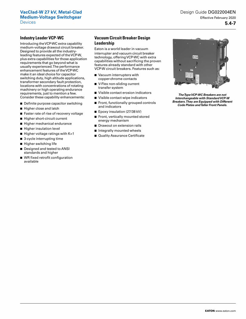
Industry Leader VCP-WCIntroducing the VCP-WC extra capabil ity medium-voltage drawout circuit breaker. Designed to provide all the industry-leading features expected of the VCP-W, plus extra capabilities for those application requirements that go beyond what is usually experienced. The performance enhancement fea tures of the VCP-WC make it an ideal choice for capacitor switching duty, high altitude applications, transformer secondary fault protection, locations with concentrations of rotating machinery or high operating endur ance requirements, just to mention a few. Consider these capability enhancements:
■ Definite purpose capacitor switching■ Higher close and latch■ Faster rate of rise of recovery voltage■ Higher short-circuit current■ Higher mechanical endurance■ Higher insulation level■ Higher voltage ratings with K=1■ 3-cycle interrupting time■ Higher switching life■ Designed and tested to ANSI standards and higher
■ WR fixed retrofit configuration available
Vacuum Circuit Breaker Design LeadershipEaton is a world leader in vacuum interrupter and vacuum circuit breaker technology, offering VCP-WC with extra capabilities without sacrificing the proven features already standard with other VCP-W circuit breakers. Features such as:
■ Vacuum interrupters with copper-chrome contacts
■ V-Flex non-sliding current transfer system
■ Visible contact erosion indicators■ Visible contact wipe indicators■ Front, functionally grouped controls and indicators
■ Epoxy insulation (27/38 kV)■ Front, vertically mounted stored energy mechanism
■ Drawout on extension rails■ Integrally mounted wheels■ Quality Assurance Certificate
The Type VCP-WC Breakers are not Interchangeable with Standard VCP-W
Breakers. They are Equipped with Different Code Plates and Taller Front Panels.
Design Guide DG022004EN Effective February 2020
5 .4-7
VacClad-W 27 kV, Metal-CladMedium-Voltage SwitchgearDevices
EATON www.eaton.com
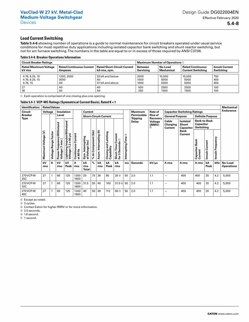
Load Current SwitchingTable 5 .4-6 showing number of operations is a guide to normal main tenance for circuit breakers operated under usual service conditions for most repetitive duty applications including isolated capacitor bank switching and shunt reactor switching, but not for arc furnace switching. The numbers in the table are equal to or in excess of those required by ANSI C37.06.
Table 5.4-6. Breaker Operations Information Circuit Breaker Ratings Maximum Number of Operations a
Rated Maximum Voltage kV rms
Rated Continuous Current Amperes
Rated Short-Circuit Current kA rms, sym .
Between Servicing
No-Load Mechanical
Rated ContinuousCurrent Switching
Inrush Current Switching
4.76, 8.25, 15 4.76, 8.25, 15 4.76, 15
1200, 20003000All
33 kA and belowAll37 kA and above
200010001000
10,000 5000 5000
10,000 5000 5000
750400400
2738
AllAll
AllAll
500 250
2500 1500
2500 1500
100100
a Each operation is comprised of one closing plus one opening.
Table 5.4-7. VCP-WC Ratings (Symmetrical Current Basis), Rated K = 1 Identification Rated Values Mechanical
EnduranceCircuitBreakerType
Voltage InsulationLevel
Co
nti
nu
ou
s C
urr
ent
at 6
0 H
z
Current
Inte
rru
pti
ng
Tim
e c
MaximumPermissibleTrippingDelay
Rate ofRise ofRecoveryVoltage(RRRV)d
Capacitor Switching Ratings
Max
imu
m V
olt
age
(V)
Vo
ltag
e R
ange
Fac
tor
Short-Circuit Current General Purpose Definite Purpose
Pow
er F
req
uen
cy W
ith
stan
d
Vo
ltag
e (1
min
.)
Lig
htn
ing
Imp
uls
e W
ith
stan
d
Vo
ltag
e (1
.2 x
50
µs)
Sym
. In
terr
up
tin
g
at V
olt
age
(Isc
)
% d
c C
om
po
nen
t (I
dc)
Asy
m . I
nte
rru
pti
ng
(It)
Clo
sin
g a
nd
Lat
chin
gC
apab
ility
Sh
ort
-Tim
e C
urr
ent
for
3 S
eco
nd
s b
Back-to-BackCapacitor Switching
CableChargingCurrent
IsolatedShuntCapacitor BankCurrent
Cap
acit
or
Ban
kC
urr
ent
Inru
sh C
urr
ent
Inru
sh F
req
uen
cy
kVrms
K kVrms
kVPeak
Arms
kA rmsTotal
% kArms
kAPeak
kArms
ms Seconds kV/µs A rms A rms A rms kAPeak
kHz No-LoadOperations
270 VCP-W 25C
27 1 60 125 12001600
25 75 36 85 25 e 50 2.0 1.1 — 400 400 20 4.2 5,000
270 VCP-W 32C
27 1 60 125 12001600
31.5 55 40 100 31.5 f 50 2.0 1.1 — 400 400 20 4.2 5,000
270 VCP-W 40C
27 1 60 125 12001600
40 50 49 112 40 g 50 2.0 1.1 — 400 400 20 4.2 5,000
b Except as noted.c 3 cycles.d Contact Eaton for higher RRRV or for more information.e 2.5 seconds.f 1.6 second.g 1 second.
Design Guide DG022004EN Effective February 2020
5 .4-8
VacClad-W 27 kV, Metal-CladMedium-Voltage SwitchgearDevices
EATON www.eaton.com
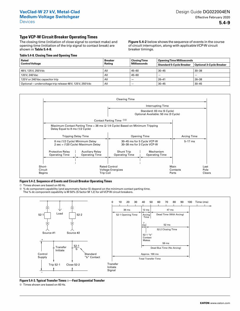
Type VCP-W Circuit Breaker Operating TimesThe closing time (initiation of close signal to contact make) and opening time (initiation of the trip signal to con tact break) are shown in Table 5 .4-8.
Figure 5 .4-2 below shows the sequence of events in the course of circuit inter ruption, along with applicable VCP-W circuit breaker timings.
Table 5.4-8. Closing Time and Opening Time Rated Control Voltage
Breaker Rating
Closing Time Milliseconds
Opening Time Milliseconds
Standard 5-Cycle Breaker Optional 3-Cycle Breaker
48 V, 125 V, 250 Vdc All 45–60 30–45 30–38
120 V, 240 Vac All 45–60 — —
120 V or 240 Vac capacitor trip All — 26–41 26–38
Optional—undervoltage trip release 48 V, 125 V, 250 Vdc All — 30–45 30–45
Figure 5.4-2. Sequence of Events and Circuit Breaker Operating Timesa Times shown are based on 60 Hz.b % dc component capability (and asymmetry factor S) depend on the minimum contact parting time.
The % dc component capability is M 50% (S factor M 1.2) for all VCP-W circuit breakers.
Figure 5.4-3. Typical Transfer Times c—Fast Sequential Transferc Times shown are based on 60 Hz.
Clearing Time
Interrupting Time
Contact Parting Time
Tripping Delay Time Opening Time
Shunt TripOperating Time
MechanismOperating Time
Protective RelayOperating Time
Auxiliary RelayOperating Time
Standard: 83 ms (5 Cycle)Optional Available: 50 ms (3 Cycle)
Maximum Contact Parting Time = 38 ms (2-1/4 Cycle) Based on Minimum TrippingDelay Equal to 8 ms (1/2 Cycle)
8 ms (1/2 Cycle) Minimum Delay2 sec = (120 Cycle) Maximum Delay
30–45 ms for 5 Cycle VCP-W30–38 ms for 3 Cycle VCP-W
Arcing Time
5–17 ms
Short-CircuitBegins
Rated ControlVoltage EnergizesTrip Coil
LastPoleClears
MainContactsParts
ab
52-1 Opening Time
Trip 52-1
ControlSupply
Source #1
52-1
Close 52-2
Source #2
TransferInitiate
52-1b
Load 52-2
Standard”b“ Contact
TransferInitiateSignal
0 10
Dead Time (With Arcing)
90
52-1 “b” ContactMakes
5030
38 ms
20
7ms
ArcingTime
12 ms
40
47 ms
7060 80 Time (ms)100
–
+
52-2 Closing Time
52 ms
Dead Bus Time (No Arcing)
59 ms
Total Transfer Time
Approx. 100 ms
Design Guide DG022004EN Effective February 2020
5 .4-9
VacClad-W 27 kV, Metal-CladMedium-Voltage SwitchgearDevices
EATON www.eaton.com
Protection Relays and MeteringA full scope of protective relays designed to meet all application requirements is available to provide the utmost in system and component protection.
Instrument TransformersInstrument transformers are used to protect personnel and secondary devices from high voltage, and permit use of reasonable insulation levels for relays, meters and instruments. The secondaries of standard instrument transformers are rated at 5 A and/or 120 V, 60 Hz.
Voltage TransformersSelection of the ratio for voltage transformers is seldom a question since the primary rating should be equal to or higher than the system line-to-line voltage. The number of potential transformers per set and their connection is determined by the type of system and the relaying and metering required.
When two VTs are used, they are typically connected L-L, and provide phase-to-phase voltages, (Vab, Vbc, Vca) for metering and relaying.
When three VTs are used, they are connected line-to-ground, and provide phase-to-phase (Vab, Vbc, Vca), as well as phase-to-ground (Va, Vb, Vc) voltages for metering and relaying.
If metering or relaying application requires phase-to-ground voltages, use three VTs, each connected L-G. If not, use of two VTs connected L-L is sufficient.
For ground detection, three VTs connected in Line-to-ground/broken- delta are used.
A single VT, when used, can be connected line-to-line (it will provide line-to-line output, for example Vab or Vbc or Vca), or line-to-ground (it will provide line-to-ground output, for example Va or Vb or Vc). Generally, a single VT is used to derive voltage signal for synchronizing or Over Voltage/Under Voltage function.
Current TransformersThe current transformer ratio is gener ally selected so that the maximum load current will read about 70% full scale on a standard 5 A coil ammeter. There fore, the current transformer primary rating should be 140–150% of the maximum load current.
Maximum system fault current can sometimes influence the current transformer ratio selection because the connected secondary devices have published one-second ratings.
The zero-sequence current transformer is used for sensitive ground fault relay ing or self-balancing primary current type machine differential protection.
The zero-sequence current transformer is available with a nominal ratio of 50/5 or 100/5 and available opening size for power cables of 7.25 inches (184.2 mm). Special zero-sequence transformers with larger windows are also available.
The minimum number of current transformers for circuit relaying and instruments is three current transform ers, one for each phase or two-phase connected current transformers and one zero-sequence current transformer. Separate sets of current transformers are required for differential relays.
The minimum pickup of a ground relay in the residual of three-phase connected current transformers is primarily determined by the current transformer ratio. The relay pickup can be reduced by adding one residual connected auxiliary current transformer. This connection is very desirable on main incoming and tie circuits of low resistance grounded circuits.
Standard accuracy current transform ers are normally more than adequate for most standard applications of micro-processor-based protective relays and meters.
Table 5.4-9. Standard Voltage Transformer Ratio Information Rating-Volts 2400 4200 4800 7200 8400 10800 12000 14400 15600 18000 21000 24000 27000 36000
Ratio 20-1 35-1 40-1 60-1 70-1 90-1 100-1 120-1 130-1 150-1 175-1 200-1 225-1 300-1
Design Guide DG022004EN Effective February 2020
5 .4-10
VacClad-W 27 kV, Metal-CladMedium-Voltage SwitchgearDevices
EATON www.eaton.com
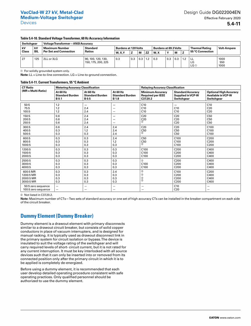
Table 5.4-10. Standard Voltage Transformer, 60 Hz Accuracy Information Switchgear Voltage Transformer—ANSI Accuracy
kVClass
kVBIL
Maximum NumberPer Set and Connection
StandardRatios
Burdens at 120 Volts Burdens at 69 .3 Volts Thermal Rating55 °C Connection
Volt-Ampere
W, X, Y Z M ZZ W, X Y M Z
27 125 2LL or 3LG 90, 100, 120, 130, 150, 175, 200, 225
0.3 0.3 0.3 1.2 0.3 0.3 0.3 1.2 LLLGLG a
1000 5501000
a For solidly grounded system only.Note: LL = Line-to-line connection. LG = Line-to-ground connection.
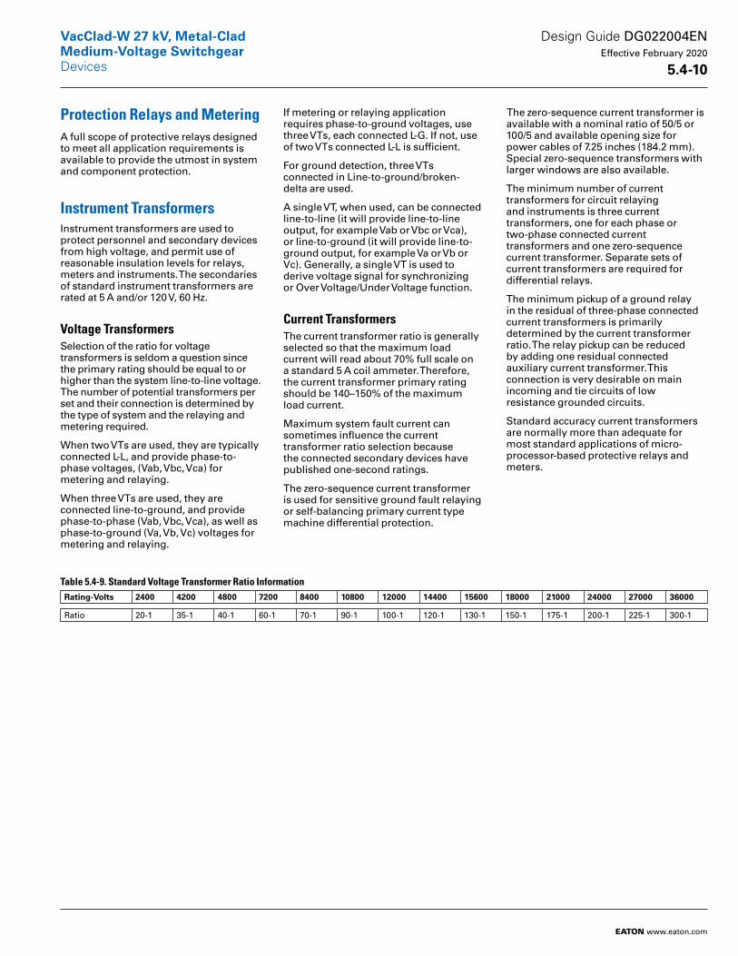
Table 5.4-11. Current Transformers, 55 °C Ambient CT Ratio(MR = Multi-Ratio)
Metering Accuracy Classification Relaying Accuracy Classification
At 60 HzStandard BurdenB 0 .1
At 60 HzStandard BurdenB 0 .5
At 60 HzStandard BurdenB 1 .8
Minimum AccuracyRequired per IEEEC37 .20 .2
Standard AccuracySupplied in VCP-WSwitchgear
Optional High AccuracyAvailable in VCP-W Switchgear
50:5 75:5 100:5
1.21.21.2
—2.42.4
———
C10C10C10
—C10C10
C10C20C20
150:5 200:5 250:5
0.60.60.6
2.42.42.4
———
C20C20b
C20C20C20
C50C50C50
300:5 400:5 500:5
0.60.30.3
2.41.20.3
2.42.42.4
C20C50b
C20C50C50
C100C100C100
600:5 800:51000:5
0.30.30.3
0.30.30.3
2.4 1.20.3
C50C50b
C100C100C100
C200C200C200
1200:51500:52000:5
0.30.30.3
0.30.30.3
0.30.30.3
C100C100C100
C200C200C200
C400C400C400
2500:53000:54000:5
0.30.30.3
0.30.30.3
0.30.30.3
b
C100C100
C200C200C200
C400C400C400
600:5 MR1200:5 MR2000:5 MR3000:5 MR
0.30.30.30.3
0.30.30.30.3
2.4 0.30.30.3
b
b
bb
C100C200C200C200
C200C400C400C400
50:5 zero sequence 100:5 zero sequence
——
——
——
——
C10C20
——
b Not listed in C37.20.2.Note: Maximum number of CTs—Two sets of standard accuracy or one set of high accuracy CTs can be installed in the breaker compartment on each side of the circuit breaker.
Dummy Element (Dummy Breaker)Dummy element is a drawout element with primary disconnects similar to a drawout circuit breaker, but consists of solid copper conductors in place of vacuum interrupters, and is designed for manual racking. it is typically used as drawout disconnect link in the primary system for circuit isolation or bypass. The device is insulated to suit the voltage rating of the switchgear and will carry required levels of short- circuit current, but it is not rated for any current interruption. It must be key interlocked with all source devices such that it can only be inserted into or removed from its connected position only after the primary circuit in which it is to be applied is completely de-energized.
Before using a dummy element, it is recommended that each user develop detailed operating procedure consis tent with safe operating practices. Only qualified personnel should be authorized to use the dummy element.
Design Guide DG022004EN Effective February 2020
5 .4-11
VacClad-W 27 kV, Metal-CladMedium-Voltage SwitchgearDevices
EATON www.eaton.com
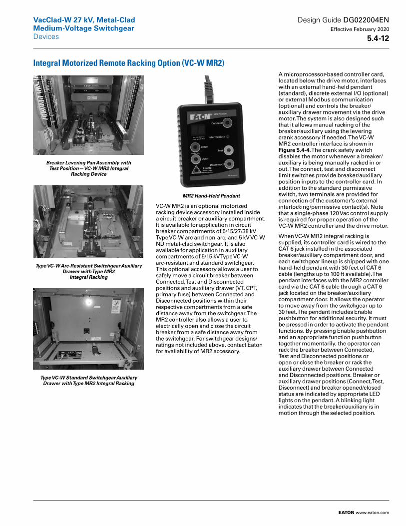
Integral Motorized Remote Racking Option (VC-W MR2)
Breaker Levering Pan Assembly with Test Position—VC-W MR2 Integral
Racking Device
Type VC-W Arc-Resistant Switchgear Auxiliary Drawer with Type MR2
Integral Racking
Type VC-W Standard Switchgear Auxiliary Drawer with Type MR2 Integral Racking
MR2 Hand-Held Pendant
VC-W MR2 is an optional motorized racking device accessory installed inside a circuit breaker or auxiliary compartment. It is available for application in circuit breaker compart ments of 5/15/27/38 kV Type VC-W arc and non-arc, and 5 kV VC-W ND metal-clad switchgear. It is also available for application in auxiliary compartments of 5/15 kV Type VC-W arc-resistant and standard switchgear. This optional accessory allows a user to safely move a circuit breaker between Connected, Test and Disconnected positions and auxiliary drawer (VT, CPT, primary fuse) between Connected and Disconnected positions within their respective compartments from a safe distance away from the switchgear. The MR2 controller also allows a user to electri cally open and close the circuit breaker from a safe distance away from the switchgear. For switchgear designs/ratings not included above, contact Eaton for availability of MR2 accessory.
A microprocessor-based controller card, located below the drive motor, interfaces with an external hand-held pendant (standard), discrete external I/O (optional) or external Modbus communication (optional) and controls the breaker/auxiliary drawer move ment via the drive motor. The system is also designed such that it allows manual racking of the breaker/auxiliary using the levering crank accessory if needed. The VC-W MR2 controller interface is shown in Figure 5 .4-4. The crank safety switch disables the motor whenever a breaker/auxiliary is being manually racked in or out. The connect, test and disconnect limit switches provide breaker/auxiliary position inputs to the controller card. In addition to the standard permissive switch, two terminals are provided for connection of the customer’s external interlocking/permissive contact(s). Note that a single-phase 120 Vac control supply is required for proper operation of the VC-W MR2 controller and the drive motor.
When VC-W MR2 integral racking is supplied, its controller card is wired to the CAT 6 jack installed in the associated breaker/auxiliary compart ment door, and each switchgear lineup is shipped with one hand-held pendant with 30 feet of CAT 6 cable (lengths up to 100 ft available). The pendant interfaces with the MR2 controller card via the CAT 6 cable through a CAT 6 jack located on the breaker/auxiliary compartment door. It allows the operator to move away from the switchgear up to 30 feet. The pendant includes Enable pushbutton for additional security. It must be pressed in order to activate the pendant functions. By pressing Enable pushbutton and an appropriate function pushbutton together momentarily, the operator can rack the breaker between Connected, Test and Disconnected positions or open or close the breaker or rack the auxiliary drawer between Connected and Disconnected positions. Breaker or auxiliary drawer positions (Connect, Test, Disconnect) and breaker opened/closed status are indicated by appropriate LED lights on the pendant. A blinking light indicates that the breaker/auxiliary is in motion through the selected position.
Design Guide DG022004EN Effective February 2020
5 .4-12
VacClad-W 27 kV, Metal-CladMedium-Voltage SwitchgearDevices
EATON www.eaton.com

A solid (non-blinking) light indicates that the breaker/auxiliary has reached and stopped in the selected position. In case normal operation fails, the appropriate error code is displayed in a separate two-character LED display window on the pendant. A list of various error codes and their descrip tions along with suggested corrective actions are printed on the back side of the pendant. Examples of error states: motor overcurrent, motor overtemperature, motor timed out, breaker position unknown, open permissive, communication error and no breaker/auxiliary.
In addition to pendant, three optional I/O interfaces can be supplied as follows:
1. I/O interface to allow racking of breaker (connect, test, disconnect) or auxiliary drawer (connect, disconnect) by external hardwired dry contacts and 24 Vdc output for corresponding remote position indicating LEDs.
2. I/O board that provided dry contacts for remote indication of breaker (connect, intermediate, test, disconnect)/auxiliary drawer (connect, test) position within its compartment.
3. I/O interface to allow breaker open/close functions via external hardwired dry contacts and 24 Vdc output for corresponding remote open/close status LEDs.
The remote LED lights are not included with MR2. If the customer needs to operate the MR2 with the hand-held pendant, the pendant becomes the master and will override the customer’s remote control signals.
The VC-W MR2 controller is also equipped with terminal blocks to allow the customer to interface with the controller via their SCADA system using a Modbus interface. Please note that only one of the two options, discrete I/O interface or Modbus interface, can be used, but not both. Figure 5 .4-5 shows an illustration of a typical Modbus control example. Additional compo nents shown outside the MR2 controller in Figure 5 .4-5 are not included with the MR2. System-level controls can be optionally supplied by Eaton’s Engineering Services & Systems. If the customer needs to operate the MR2 with the hand-held pendant, the pendant becomes the master and will override the Modbus interface. Error codes are displayed on Modbus devices when controlling the MR2 with Modbus and on the pendant when controlling with the pendant.
Technical Data
Control Supply Ratings■ Nominal control voltage—120 Vac, 50 or 60 Hz, single-phase
■ Control voltage range—100 to 140 Vac, 50 or 60 Hz
■ Time to travel from connect to disconnect, or disconnect to connect—50 seconds maximum
■ Current draw during the travel—15 A maximum for about 3 seconds and 3.6 A for about 24 seconds
■ Optional dry output contacts when included for position indications are rated for 125 Vac, 2 A
■ External permissive contacts, when used, must be rated for 24 Vdc, 50 mA
Requirements for External Contacts and LEDs when Interfacing with MR2
■ External contacts should be rated for minimum open circuit voltage of 24 Vdc, and be able to close and carry 5 mA at 24 Vdc
■ When remote LEDs are used, use 24 Vdc rated LEDs, current up to 20 mA
■ Optional dry output contacts when included for position indications are rated for 125 Vac, 2 A
■ External permissive contacts, when used, must be rated for 24 Vdc, 50 mA
It is the customer’s responsibility to provide single-phase 120 V, 50 or 60 Hz nominal supply for the MR2 controller. It can be derived from within the switchgear if an appropriate control power transformer is available within the switchgear.
Type VC-W MR2 motorized racking accessory has been endurance tested and guaranteed for 500 operations as required by IEEE C37.20.2.
Design Guide DG022004EN Effective February 2020
5 .4-13
VacClad-W 27 kV, Metal-CladMedium-Voltage SwitchgearDevices
EATON www.eaton.com
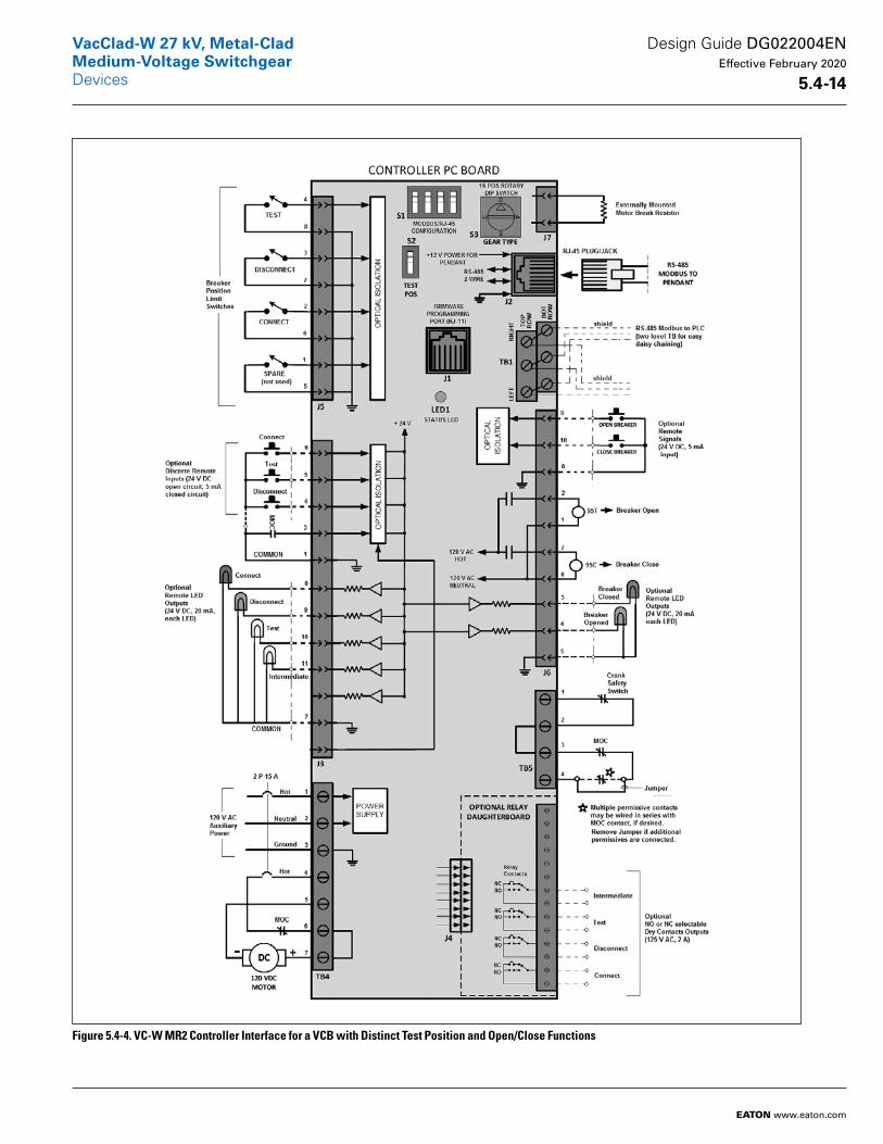
Figure 5.4-4. VC-W MR2 Controller Interface for a VCB with Distinct Test Position and Open/Close Functions
Design Guide DG022004EN Effective February 2020
5 .4-14
VacClad-W 27 kV, Metal-CladMedium-Voltage SwitchgearDevices
EATON www.eaton.com
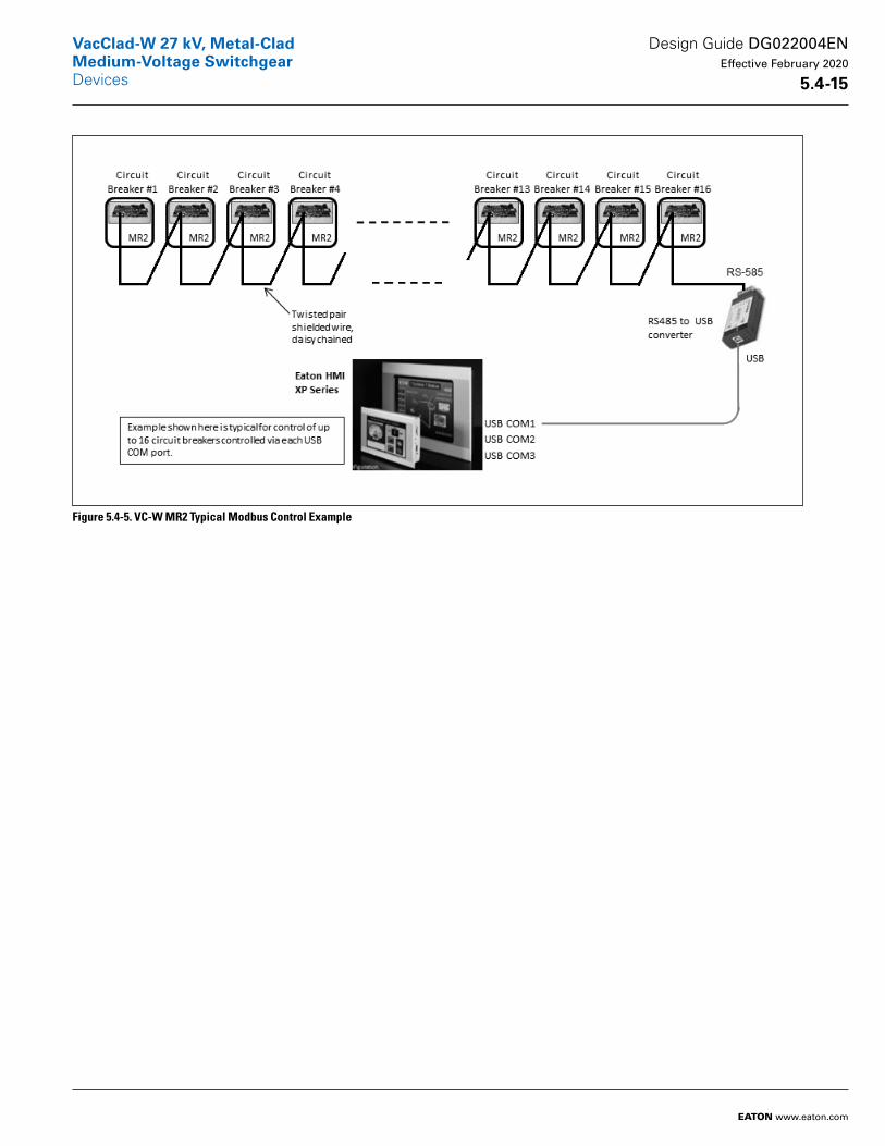
Figure 5.4-5. VC-W MR2 Typical Modbus Control Example
Design Guide DG022004EN Effective February 2020
5 .4-15
VacClad-W 27 kV, Metal-CladMedium-Voltage SwitchgearDevices
EATON www.eaton.com
Accessories
Ground and Test DeviceThe ground and test device is a drawout element that may be inserted into a metal-clad switchgear housing in place of a circuit breaker to provide access to the primary circuits to permit the tem porary connection of grounds or test ing equipment to the high-voltage circuits. High potential testing of cable or phase checking of circuits are typical tests which may be performed. The devices are insulated to suit the voltage rating of the switchgear and will carry required level of short-circuit current.
Before using ground and test devices, it is recommended that each user develop detailed operating procedures consis tent with safe operating practices. Only qualified personnel should be authorized to use ground and test devices.
Manual and electrical ground and test devices are available, These devices include six studs for connection to primary circuits. On the manual device, selection and grounding is accomplished by cable or bus bars connection. On electrical-type devices, grounding is accomplished by an electrically operated grounding switch.
Standard Accessories■ One test jumper■ One levering crank■ One maintenance tool■ One lifting yoke (5–27 kV)■ One sets of rails (5–27 kV)■ One turning handle (5th wheel, 38 kV)
Optional Accessories■ Transport dolly (5–27 kV), (5–15 kV arc-resistant)
■ Portable lifter (5–27 kV)■ Test cabinet■ Electrical levering device (5–38 kV)■ Ramp for lower breaker (5–27 kV), (5–15 kV arc-resistant)
■ Manual or electrical ground and test device
■ Hi-pot tester■ Integral motorized remote racking (VC-W MR2) for circuit breaker
■ Integral motorized remote racking (VC-W MR2) for auxiliary drawer
Design Guide DG022004EN Effective February 2020
5 .4-16
VacClad-W 27 kV, Metal-CladMedium-Voltage SwitchgearDevices
EATON www.eaton.com
System Options
Partial Discharge Sensing and Monitoring for Switchgear
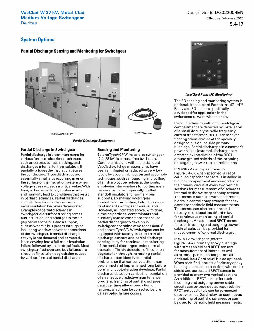
Partial Discharge Equipment
Partial Discharge in SwitchgearPartial discharge is a common name for various forms of electrical discharges such as corona, surface tracking, and discharges internal to the insulation. It partially bridges the insulation between the conductors. These discharges are essentially small arcs occurring in or on the surface of the insulation system when voltage stress exceeds a critical value. With time, airborne particles, contaminants and humidity lead to conditions that result in partial discharges. Partial discharges start at a low level and increase as more insulation becomes deteriorated. Examples of partial discharge in switchgear are surface tracking across bus insulation, or discharges in the air gap between the bus and a support, such as where a bus passes through an insulating window between the sections of the switchgear. If partial discharge activity is not detected and corrected, it can develop into a full-scale insulation failure followed by an electrical fault. Most switchgear flashover and bus failures are a result of insulation degradation caused by various forms of partial discharges.
Sensing and MonitoringEaton’s Type VCP-W metal-clad switch gear (2.4–38 kV) is corona-free by design. Corona emissions within the standard VacClad switchgear assemblies have been eliminated or reduced to very low levels by special fabrication and assembly techniques, such as rounding and buffing of all sharp copper edges at the joints, employing star washers for bolting metal barriers, and using specially crafted standoff insulators for primary bus supports. By making switchgear assemblies corona-free, Eaton has made its standard switchgear more reliable. However, as indicated above, with time, airborne particles, contaminants and humidity lead to conditions that cause partial discharges to develop in switchgear operating at voltages 4000 V and above. Type VC-W switchgear can be equipped with fac tory-installed partial discharge sensors and partial discharge sensing relay for continuous monitoring of the partial discharges under normal operation. Timely detection of insulation degrada tion through increasing partial discharges can identify potential problems so that corrective actions can be planned and implemented long before permanent deterioration develops. Partial discharge detection can be the foundation of an effective predictive maintenance program. Trending of partial discharge data over time allows prediction of failures, which can be corrected before catastrophic failure occurs.
InsulGard Relay (PD Monitoring)
The PD sensing and monitoring system is optional. It consists of Eaton’s InsulGard™ Relay and PD sensors specifically developed for application in the switchgear to work with the relay.
Partial discharges within the switch gear compartment are detected by installation of a small donut type radio frequency current transformer (RFCT) sensor over floating stress shields of the specially designed bus or line side primary bushings. Partial discharges in customer’s power cables (external discharges) are detected by installation of the RFCT around ground shields of the incoming or outgoing power cable terminations.
In 27/38 kV switchgear (refer to Figure 5 .4-8), when specified, a set of coupling capacitor sensors is installed in the rear compartment and connected to the primary circuit at every two vertical sections for measurement of discharges internal to the switchgear compartment. The sensor’s output is wired to terminal blocks in control compartment for easy access for periodic field measurements. The sensor can also be connected directly to optional InsulGard relay for continu ous monitoring of partial discharges. An additional RFCT sensor for each incoming and outgoing power cable circuits can be provided for measure ment of external discharges.
In 5/15 kV switchgear (refer to Figure 5 .4-7), primary epoxy bushings with stress shield and RFCT sensors for measurement of internal as well as external partial discharges are all optional. InsulGard relay is also optional. When specified, one set of primary epoxy bushings (located on bus side) with stress shield and associ ated RFCT sensor is provided at every two vertical sections. An additional RFCT sensor for each incoming and outgoing power cable circuits can be provided as required. The RFCT output signals can be connected directly to InsulGard relay for continuous moni toring of partial discharges or can be used for periodic field measurements.
RFCT SensorInsulGard Relay
Design Guide DG022004EN Effective February 2020
5 .4-17
VacClad-W 27 kV, Metal-CladMedium-Voltage SwitchgearDevices
EATON www.eaton.com
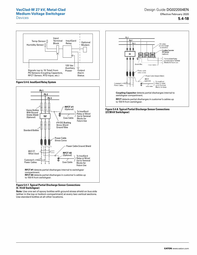
Figure 5.4-6. InsulGard Relay System
Figure 5.4-7. Typical Partial Discharge Sensor Connections (5–15 kV Switchgear)Note: Use one set of epoxy bottles with ground stress shield on bus side (either in the top or bottom compartment) at every two vertical sections. Use standard bottles at all other locations.
Figure 5.4-8. Typical Partial Discharge Sensor Connections (27/38 kV Switchgear)
InputTerminalBlock
InsulGardRelay Optional
Modem
Temp Sensor
Humidity Sensor
OutputAlarmStatus
120 VacAuxiliaryPowerSignals (up to 15 Total) from
PD Sensors (Coupling Capacitors,RFCT Sensor, RTD Input, etc.)
RFCT #1 detects partial discharges internal to switchgear compartment.RFCT #2 detects partial discharges in customer’s cables up to 100 ft from switchgear.
Coupling Capacitor detects partial discharges internal to switchgear compartment.
RFCT detects partial discharges in customer’s cables up to 100 ft from switchgear.
Design Guide DG022004EN Effective February 2020
5 .4-18
VacClad-W 27 kV, Metal-CladMedium-Voltage SwitchgearDevices
EATON www.eaton.com
Partial Discharge Sensors and Monitoring for Switchgear
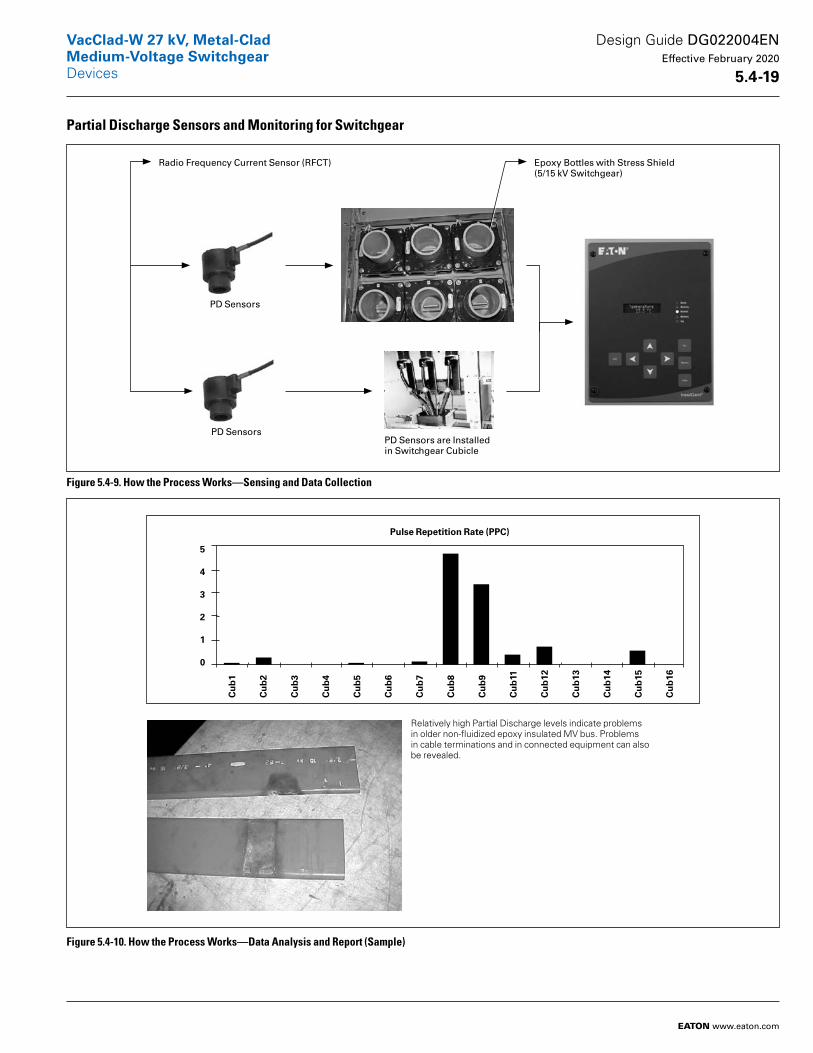
Figure 5.4-9. How the Process Works—Sensing and Data Collection
Figure 5.4-10. How the Process Works—Data Analysis and Report (Sample)
Radio Frequency Current Sensor (RFCT)
PD SensorsPD Sensors are Installed in Switchgear Cubicle
PD Sensors
Epoxy Bottles with Stress Shield (5/15 kV Switchgear)
Relatively high Partial Discharge levels indicate problems in older non-fluidized epoxy insulated MV bus. Problems in cable terminations and in connected equipment can also be revealed.
Pulse Repetition Rate (PPC)
5
4
3
2
1
0
Cu
b1
Cu
b2
Cu
b3
Cu
b4
Cu
b5
Cu
b6
Cu
b7
Cu
b8
Cu
b9
Cu
b11
Cu
b12
Cu
b13
Cu
b14
Cu
b15
Cu
b16
Design Guide DG022004EN Effective February 2020
5 .4-19
VacClad-W 27 kV, Metal-CladMedium-Voltage SwitchgearDevices
EATON www.eaton.com
Standard
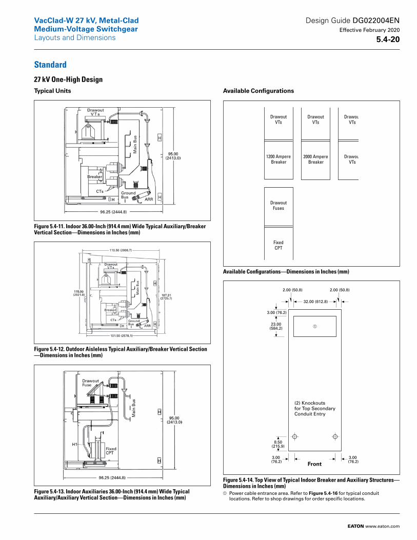
27 kV One-High DesignTypical Units
Figure 5.4-11. Indoor 36.00-Inch (914.4 mm) Wide Typical Auxiliary/Breaker Vertical Section—Dimensions in Inches (mm)
Figure 5.4-12. Outdoor Aisleless Typical Auxiliary/Breaker Vertical Section —Dimensions in Inches (mm)
Figure 5.4-13. Indoor Auxiliaries 36.00-Inch (914.4 mm) Wide Typical Auxiliary/Auxiliary Vertical Section—Dimensions in Inches (mm)
Available Configurations
Available Configurations—Dimensions in Inches (mm)
Figure 5.4-14. Top View of Typical Indoor Breaker and Auxiliary Structures—Dimensions in Inches (mm)a Power cable entrance area. Refer to Figure 5 .4-16 for typical conduit
locations. Refer to shop drawings for order specific locations.
DrawoutVTs
1200 AmpereBreaker
DrawoutVTs
2000 AmpereBreaker
DrawoutVTs
DrawoutVTs
DrawoutFuses
FixedCPT
23.00(584.2)
32.00 (812.8)
3.00 (76.2)
(2) Knockoutsfor Top SecondaryConduit Entry
8.50(215.9)
2.00 (50.8) 2.00 (50.8)
3.00 (76.2)
3.00 (76.2) Front
Design Guide DG022004EN Effective February 2020
5 .4-20
VacClad-W 27 kV, Metal-CladMedium-Voltage Switchgear
EATON www.eaton.com
Layouts and Dimensions
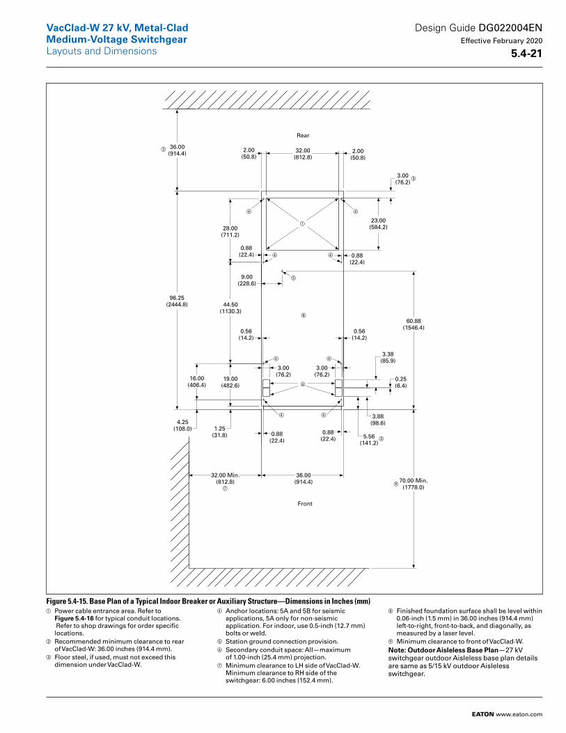
Figure 5.4-15. Base Plan of a Typical Indoor Breaker or Auxiliary Structure—Dimensions in Inches (mm)a Power cable entrance area. Refer to
Figure 5 .4-16 for typical conduit locations. Refer to shop drawings for order specific locations.
b Recommended minimum clearance to rear of VacClad-W: 36.00 inches (914.4 mm).
c Floor steel, if used, must not exceed this dimension under VacClad-W.
d Anchor locations: 5A and 5B for seismic applications, 5A only for non-seismic application. For indoor, use 0.5-inch (12.7 mm) bolts or weld.
e Station ground connection provision.f Secondary conduit space: All—maximum
of 1.00-inch (25.4 mm) projection.g Minimum clearance to LH side of VacClad-W.
Minimum clearance to RH side of the switchgear: 6.00 inches (152.4 mm).
h Finished foundation surface shall be level within 0.06-inch (1.5 mm) in 36.00 inches (914.4 mm) left-to-right, front-to-back, and diagonally, as measured by a laser level.
i Minimum clearance to front of VacClad-W.Note: Outdoor Aisleless Base Plan—27 kV switchgear outdoor Aisleless base plan details are same as 5/15 kV outdoor Aisleless switchgear.
Rear
36.00(914.4)
Front
0.88(22.4)
96.25(2444.8)
2.00(50.8)
2.00(50.8)
32.00(812.8)
23.00(584.2)28.00
(711.2)
44.50(1130.3)
19.00(482.6)
1.25(31.8)
16.00(406.4)
4.25(108.0)
32.00 Min.(812.8)
36.00(914.4)
0.56(14.2)
0.56(14.2)
3.00(76.2)
3.00(76.2)
0.25(6.4)
3.88(98.6)
5.56(141.2)
0.88(22.4)
60.88(1546.4)
70.00 Min.(1778.0)
3.00(76.2)
9.00(228.6)
3.38(85.9)
0.88(22.4)
0.88(22.4)
a
b
c
d
e
f
g
h
i
d
d d
d d
d d
c
Design Guide DG022004EN Effective February 2020
5 .4-21
VacClad-W 27 kV, Metal-CladMedium-Voltage SwitchgearLayouts and Dimensions
EATON www.eaton.com

Figure 5.4-16. Primary Conduit Locations for Top or Bottom Entry—Dimensions in Inches (mm)a Changes to 8.25 inches (209.6 mm) if optional hinged rear doors
are required.
Figure 5.4-17. Maximum Hinged Panel Equipment— Dimensions in Inches (mm)Note: The figure above shows that the arrangement of components differs between upper and lower panels. The figure may also be used to select custom arrange ments of hinged panel components. Also, the use of multi-function relays such as Eaton’s E-series relays will significantly reduce consumption of panel space.
11.50 (292.1)
Two Conduits
Four Conduits
7.00 (177.8)
6.00 (152.4)6.00 (152.4)
a
1 1 1 2
2 2 2 7
4
4
3 3 3 3 3
6 5 5
UpperHingedPanel
LowerHingedPanel
1-Large RelayCase
2-Small RelayCase
3-Instrument4-Test Switch5-Switch6-Lock-out
Relay orSwitch
7-MeteringUnitNo devices on the
breaker compartmentdoor.
Design Guide DG022004EN Effective February 2020
5 .4-22
VacClad-W 27 kV, Metal-CladMedium-Voltage SwitchgearLayouts and Dimensions
EATON www.eaton.com
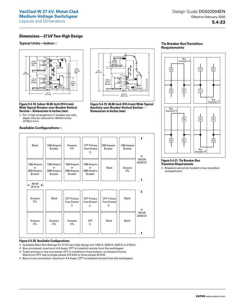
Dimensions—27 kV Two-High Design
Typical Units—Indoor a
Figure 5.4-18. Indoor 36.00-Inch (914.4 mm) Wide Typical Breaker-over-Breaker Vertical Section—Dimensions in Inches (mm)a For 1-high arrangement (1 breaker per cell),
depth may be reduced to 108.64 inches (2759.5 mm).
Figure 5.4-19. 36.00-Inch (914.4 mm) Wide Typical Auxiliary-over-Breaker Vertical Section—Dimensions in Inches (mm)
Available Configurations b
Figure 5.4-20. Available Configurationsb Available Main Bus Ratings for 27 kV two-high design are 1200 A, 2000 A, 2500 A or 2700 A.c Bus connected, maximum 4 A fuses. CPT is installed remote from the switchgear.d Fuses are bus or line connected. CPT is installed in front bottom, on drawout frame.
Maximum CPT size is single-phase 37.5 kVA or three-phase 45 kVA.e Bus or Line connected, maximum 4 A fuses. CPT is installed remote from the switchgear.
Tie Breaker Bus Transition Requirements
Figure 5.4-21. Tie Breaker Bus Transition Requirementsf Breakers cannot be located in bus transition
compartment.
Blank 1200 AmpereBreaker
1200 AmpereBreaker
1200 AmpereBreaker
DrawoutVTs
DrawoutVTs
Blank
DrawoutVTs
DrawoutVTs
DrawoutVTs
CPT PrimaryFuse Drawer
1200 Ampereor
2000 AmpereBreaker
1200 Ampereor
2000 AmpereBreaker
CPT PrimaryFuse Drawer
CPT PrimaryFuse Drawer
CPT PrimaryFuse Drawer
1200 Ampereor
2000 AmpereBreaker
1200 Ampereor
2000 AmpereBreaker
Blank DrawoutVTs
CPT
Blank
BlankBlank
H100.00
(2540.0)
36.00(914.4)
H100.00
(2540.0)
c
c d e
d
f
f
f
f
Design Guide DG022004EN Effective February 2020
5 .4-23
VacClad-W 27 kV, Metal-CladMedium-Voltage SwitchgearLayouts and Dimensions
EATON www.eaton.com

Figure 5.4-22. Typical Indoor Floor Plan—27 kV Two-High
10.96(278.4)
36.00(914.4)
Front
0.59(15.0)
0.59(15.0)
1.25(31.8)
27.00
(177.8)
7
36.00(914.4)Min.
BusCompt.
118.64(3013.5)
LineCompt.
5
32.00(812.8)
Rear
48.00(1219.2)
9.00(228.6)
0.88(22.4)
2.00(50.8)
2.00(50.8)
1
1
1
8
6
3.00(76.2)
72.00(1828.8)
Min.
3 7.38(187.5)
1
65.97(1675.6)
6
8
7
5
4
3
2
3.00(76.2)
7.80(198.1)
1
22.25(565.2)
BreakerCompt.
ControlCompt.
Knockouts for 1.38" (35.1)or 1.75 (44.5) Conduits
Top Entry Secondary Control
Anchor locations for 0.50-inch (12.7 mm) bolts SAE Grade 5 or better, (6) places in each vertical section.
Secondary control wiring conduit openings, conduit projection must not exceed 1.00 inch (25.4 mm).
Minimum front clearance when using Eaton’s portable lifter.
Minimum left-hinged panel clearance.Minimum clearance to RH side of the switchgear: 6.00 inches (152.4 mm).
Recommended minimum rear clearance.
Finished foundation surface shall be level within 0.06-inch (1.5 mm) in 36.00 inches (914.4 mm) left-to-right, front-to-back, and diagonally, as measured by a laser level.
Primary (H.V.) conduit projection must not exceed 2.00 inches (50.8 mm). See shop order base plan for conduit locations.
Customer’s ground provisions, provided as shown by symbol on shop order sectional side views.
32.00(812.8)Min.4
25.00(635.0)
0.88(22.4)
3.00(76.2)
3.00(76.2)
36.00(914.4)
3.00(76.2)
3.00(76.2)
Design Guide DG022004EN Effective February 2020
5 .4-24
VacClad-W 27 kV, Metal-CladMedium-Voltage SwitchgearLayouts and Dimensions
EATON www.eaton.com
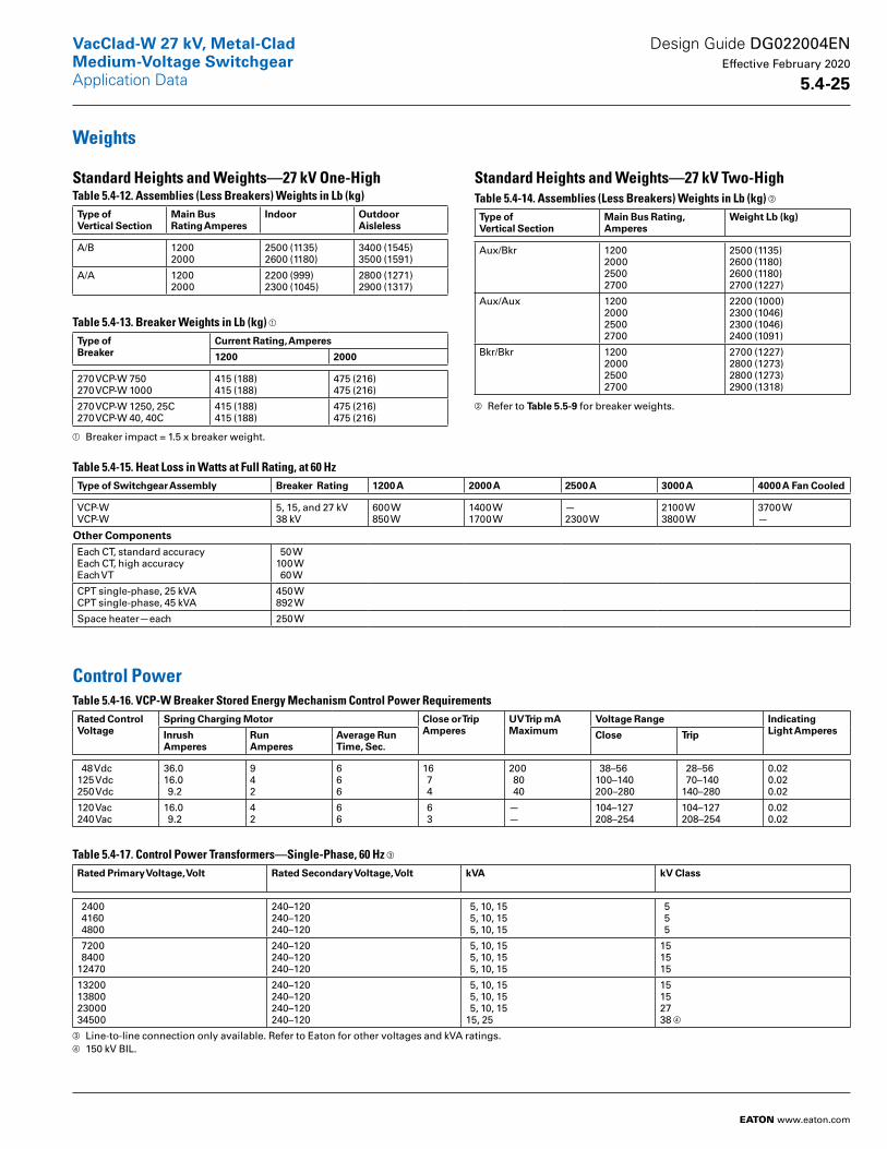
Weights
Standard Heights and Weights—27 kV One-HighTable 5.4-12. Assemblies (Less Breakers) Weights in Lb (kg)Type of Vertical Section
Main Bus Rating Amperes
Indoor Outdoor Aisleless
A/B 12002000
2500 (1135)2600 (1180)
3400 (1545)3500 (1591)
A/A 12002000
2200 (999)2300 (1045)
2800 (1271)2900 (1317)
Table 5.4-13. Breaker Weights in Lb (kg) a Type ofBreaker
Current Rating, Amperes
1200 2000
270 VCP-W 750270 VCP-W 1000
415 (188)415 (188)
475 (216)475 (216)
270 VCP-W 1250, 25C270 VCP-W 40, 40C
415 (188)415 (188)
475 (216)475 (216)
a Breaker impact = 1.5 x breaker weight.
Standard Heights and Weights—27 kV Two-HighTable 5.4-14. Assemblies (Less Breakers) Weights in Lb (kg) b
Type of Vertical Section
Main Bus Rating, Amperes
Weight Lb (kg)
Aux/Bkr 1200200025002700
2500 (1135)2600 (1180)2600 (1180)2700 (1227)
Aux/Aux 1200200025002700
2200 (1000)2300 (1046)2300 (1046)2400 (1091)
Bkr/Bkr 1200200025002700
2700 (1227)2800 (1273)2800 (1273)2900 (1318)
b Refer to Table 5 .5-9 for breaker weights.
Table 5.4-15. Heat Loss in Watts at Full Rating, at 60 HzType of Switchgear Assembly Breaker Rating 1200 A 2000 A 2500 A 3000 A 4000 A Fan Cooled
VCP-WVCP-W
5, 15, and 27 kV38 kV
600 W850 W
1400 W1700 W
—2300 W
2100 W3800 W
3700 W—
Other ComponentsEach CT, standard accuracyEach CT, high accuracyEach VT
50 W100 W 60 W
CPT single-phase, 25 kVACPT single-phase, 45 kVA
450 W892 W
Space heater—each 250 W
Control PowerTable 5.4-16. VCP-W Breaker Stored Energy Mechanism Control Power Requirements Rated Control Voltage
Spring Charging Motor Close or Trip Amperes
UV Trip mA Maximum
Voltage Range Indicating Light AmperesInrush
AmperesRun Amperes
Average Run Time, Sec .
Close Trip
48 Vdc125 Vdc250 Vdc
36.016.0 9.2
942
666
16 7 4
200 80 40
38–56100–140200–280
28–56 70–140140–280
0.020.020.02
120 Vac240 Vac
16.0 9.2
42
66
6 3
——
104–127208–254
104–127208–254
0.020.02
Table 5.4-17. Control Power Transformers—Single-Phase, 60 Hz c Rated Primary Voltage, Volt Rated Secondary Voltage, Volt kVA kV Class
2400 4160 4800
240–120240–120240–120
5, 10, 15 5, 10, 15 5, 10, 15
5 5 5
7200 840012470
240–120240–120240–120
5, 10, 15 5, 10, 15 5, 10, 15
151515
13200138002300034500
240–120240–120240–120240–120
5, 10, 15 5, 10, 15 5, 10, 1515, 25
15152738 d
c Line-to-line connection only available. Refer to Eaton for other voltages and kVA ratings.d 150 kV BIL.
Design Guide DG022004EN Effective February 2020
5 .4-25
VacClad-W 27 kV, Metal-CladMedium-Voltage Switchgear
EATON www.eaton.com
Application Data
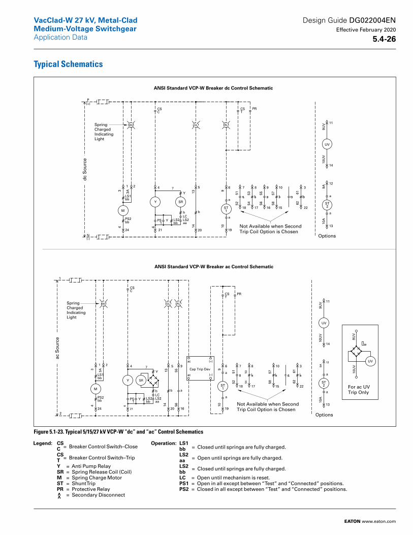
Typical Schematics
Figure 5.1-23. Typical 5/15/27 kV VCP-W “dc” and “ac” Control Schematics
dc
So
urc
e
N(-)
P(+)
1 2
24
LS1
3
3A
4
M
bb
PS2bb
4
21
LS2 LS2PS YLC
Y
6
Y
7
bb aa
b
1
SR
LOCATION
20
5
1314
b
LOCATIONCGL
GL
19
6
910
1
a
a
LOCATION
7
18
8
17
9
16
10
15
5152
5354
5556
5758
3
22
6162
CCBSN
CSC
TCSSLT
RL
TRCS_
CST
TRCO_51N
PR
WL
13
12
9A10
A
2
a
a
LOCATIONTCSSLTTRCS_TRCO_51N
14
11
9UV
10U
V
UV
LOCATIONTCSSLTTRCS_TRCO_51N
ST
Options
Not Available when SecondTrip Coil Option is Chosen
ANSI Standard VCP-W Breaker dc Control Schematic
ST
LOCATION
ac S
ou
rce
CAC120FUSE
1 2
24
LS1
3
3A
4
M
bb
PS2bb
4
21
LS2 LS2PS YLC
Y
6
Y
7
bb aa
b
1
SR
LOCATION
20
5
1314
b
GL
16
9
5556
a
LOCATIONCRL
RL
19
6
910
1
a
a
ac
ac (–)
Cap Trip Dev
LOCATION
S-CPUS-TRUS-MRU
CCBSN
CSC
TRSSTRCS_
CST
TRCO_51N
PR
WL
(+)
2
1
7
18
8
17
10
15
5152
5354
5758
3
22
6162
13
12
9A10
A
2
a
a
LOCATIONTCSSLTTRCS_TRCO_51N
14
11
9UV
10U
VUV
LOCATIONTCSSLTTRCS_TRCO_51N
ST
Options
Not Available when SecondTrip Coil Option is Chosen
ST
UV
9UV
10U
V
For ac UVTrip Only
ANSI Standard VCP-W Breaker ac Control Schematic
SpringChargedIndicatingLight
SpringChargedIndicatingLight
Operation: LS1 bb LS2 aa LS2 bb LC = Open until mechanism is reset. PS1 = Open in all except between “Test” and “Connected” positions. PS2 = Closed in all except between “Test” and “Connected” positions.
Legend: CS C CS T Y = Anti Pump Relay SR = Spring Release Coil (Coil) M = Spring Charge Motor ST = Shunt Trip PR = Protective Relay >> = Secondary Disconnect
= Breaker Control Switch–Close = Breaker Control Switch–Trip
= Closed until springs are fully charged. = Open until springs are fully charged. = Closed until springs are fully charged.
Design Guide DG022004EN Effective February 2020
5 .4-26
VacClad-W 27 kV, Metal-CladMedium-Voltage SwitchgearApplication Data
EATON www.eaton.com

Figure 5.1-24. Typical 38 kV VCP-W “dc” and “ac” Control Schematics
LOCATION
N(-)
CDC0FUSE
P(+)
1 2
24
LS1
3
3A
4
M
bb
PS2bb
4
21
LS2 LS2PS YLC
Y
6
Y
7
bb aa
b
1
SR
20
5
1314
b
19
6
910
a
a
LOCATION
7
18
8
17
9
16
10
15
5152
5354
5556
5758
3
22
6162
LOCATION
S-CPUS-TRUS-MRU
CSC
TCSSLTTRCS_
CST
TRCO_51N
PR
13
12
9A10
A
2
a
aLOCATIONTCSSLTTRCS_TRCO_51N
14
11
9UV
10U
V
UV
LOCATIONTCSSLTTRCS_TRCO_51N
ST
SpringChargedIndicatingLight
ST1
U1
U24
U2
U23
U3
U22
U4
U21U24
U5
U20
U6
U19
U7
U18
U8
U17
U9
U16
U10
U15
Auxiliary Switch #2 Optional
Customer Must FurnishThis ”a“ Contact fromAuxiliary Switch WhenSecond Trip Coil Optionis Chosen and Make theAppropriate Connections
Breaker dc Control Schematic
SAACCNSACCNLOCATION
LOCATION
CAC120
CAC120FUSE
MOTOR
1 2
24
LS1
3
3A
4
M
bb
PS2bb
CL_STD
4
21
LS2 LS2PS YLC
Y
6
Y
7
bb aa
b
1
SR
CL_GR
20
5
1314
b
CRL
16
9
5556
a
TRIP
19
6
910
1
a
a
ac
ac (-)
CAP TRIP DEV
LOCATION
CONTACT
S-CPU
S-CPL
S-TRU
S-TRLS-MRL
S-MRU
CSC
TRSSTRCS_
CST
TRCO_51N
PR
(+)
2
1
7
18
8
17
10
15
5152
5354
5758
3
22
6162
LOCATION
14
11
9UV
10U
V
UV
LOCATIONTCSSLTTRCS_TRCO_51N
ST
LOCATIONCAC120FUSES-CPUS-TRUS-MRU
UV
9UV
10U
V
For ac UVTrip Only
Breaker ac Control Schematic
13
12
9A10
A
2
a
aLOCATIONTCSSLTTRCS_TRCO_51N
ST
Customer Must FurnishThis ”a“ Contact fromAuxiliary Switch WhenSecond Trip Coil Optionis Chosen and Make theAppropriate Connections
U1
U24
U2
U23
U3
U22
U4
U21U24
U5
U20
U6
U19
U7
U18
U8
U17
U9
U16
U10
U15
Auxiliary Switch #2 Optional
OPTIONS
OPTIONS
dc
So
urc
e
GL RLWL
GL RLWLSpringChargedIndicatingLight
ac S
ou
rce
Operation: LS1 bb LS2 aa LS2 bb LC = Open until mechanism is reset. PS1 = Open in all except between “Test” and “Connected” positions. PS2 = Closed in all except between “Test” and “Connected” positions.
Legend: CS C CS T Y = Anti Pump Relay SR = Spring Release Coil (Coil) M = Spring Charge Motor ST = Shunt Trip PR = Protective Relay >> = Secondary Disconnect
= Breaker Control Switch–Close = Breaker Control Switch–Trip
= Closed until springs are fully charged. = Open until springs are fully charged. = Closed until springs are fully charged.
Design Guide DG022004EN Effective February 2020
5 .4-27
VacClad-W 27 kV, Metal-CladMedium-Voltage SwitchgearApplication Data
EATON www.eaton.com
Eaton1000 Eaton BoulevardCleveland, OH 44122United StatesEaton .com
© 2020 EatonAll Rights ReservedPrinted in USAPublication No . DG022004EN / Z23483February 2020
Eaton is a registered trademark.
All other trademarks are property of their respective owners.
VacClad-W 27 kV, Metal-CladMedium-Voltage SwitchgearApplication Data
Design Guide DG022004EN Effective February 2020
5 .4-28
VacClad-W 27 kV, Metal-CladMedium-Voltage Switchgear