vacuum gripper unit
TRANSCRIPT
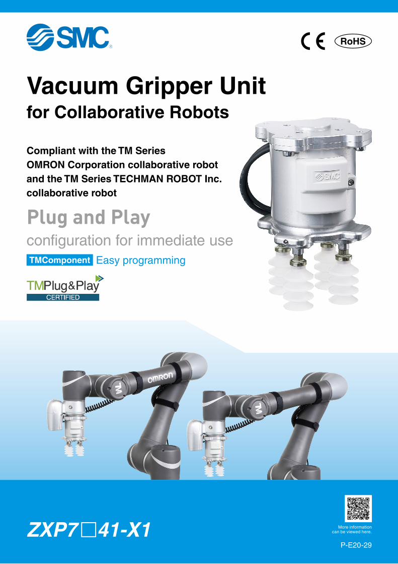
Plug and Playconfiguration for immediate use
Compliant with the TM SeriesOMRON Corporation collaborative robot and the TM Series TECHMAN ROBOT Inc. collaborative robot
Easy programmingTMComponent
Vacuum Gripper Unitfor Collaborative Robots
https://www.smcworld.com/products/en/sp/get.do?type=GUIDE&id=ZXP-X-OMRON-E&_qr=catalog
More informationcan be viewed here.
P-E20-29
ZXP7 m41-X1
RoHS
Plug and Play
Common
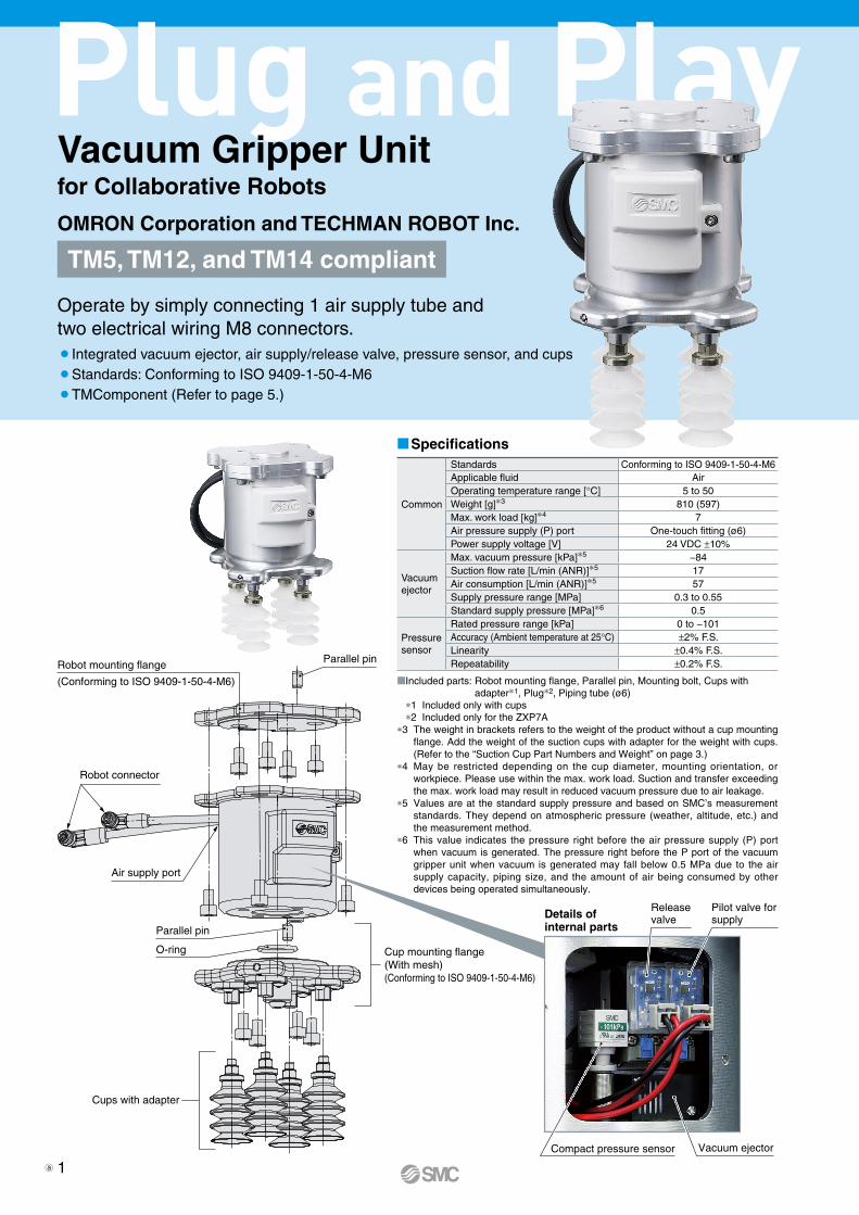
Standards Conforming to ISO 9409-1-50-4-M6Applicable fluid AirOperating temperature range [°C] 5 to 50Weight [g]*3 810 (597)Max. work load [kg]*4 7Air pressure supply (P) port One-touch fitting (ø6)Power supply voltage [V] 24 VDC ±10%
Vacuumejector
Max. vacuum pressure [kPa]*5 −84Suction flow rate [L/min (ANR)]*5 17Air consumption [L/min (ANR)]*5 57Supply pressure range [MPa] 0.3 to 0.55Standard supply pressure [MPa]*6 0.5
Pressuresensor
Rated pressure range [kPa] 0 to −101Accuracy (Ambient temperature at 25°C) ±2% F.S. Linearity ±0.4% F.S.Repeatability ±0.2% F.S.
MIncluded parts: Robot mounting flange, Parallel pin, Mounting bolt, Cups with adapter*1, Plug*2, Piping tube (ø6)
*1 Included only with cups*2 Included only for the ZXP7A
*3 The weight in brackets refers to the weight of the product without a cup mounting flange. Add the weight of the suction cups with adapter for the weight with cups.(Refer to the “Suction Cup Part Numbers and Weight” on page 3.)
*4 May be restricted depending on the cup diameter, mounting orientation, or workpiece. Please use within the max. work load. Suction and transfer exceeding the max. work load may result in reduced vacuum pressure due to air leakage.
*5 Values are at the standard supply pressure and based on SMC’s measurement standards. They depend on atmospheric pressure (weather, altitude, etc.) and the measurement method.
*6 This value indicates the pressure right before the air pressure supply (P) port when vacuum is generated. The pressure right before the P port of the vacuum gripper unit when vacuum is generated may fall below 0.5 MPa due to the air supply capacity, piping size, and the amount of air being consumed by other devices being operated simultaneously.
Release valve
Pilot valve for supply
Vacuum ejectorCompact pressure sensor
Details of internal parts
Vacuum Gripper Unitfor Collaborative Robots
Operate by simply connecting 1 air supply tube and two electrical wiring M8 connectors.¡Integrated vacuum ejector, air supply/release valve, pressure sensor, and cups¡Standards: Conforming to ISO 9409-1-50-4-M6¡TMComponent (Refer to page 5.)
MSpecifications
TM5, TM12, and TM14 compliant
OMRON Corporation and TECHMAN ROBOT Inc.
Robot mounting flange
(Conforming to ISO 9409-1-50-4-M6)
Air supply port
Cup mounting flange(With mesh)(Conforming to ISO 9409-1-50-4-M6)
Cups with adapter
Parallel pin
Parallel pin
O-ring
Robot connector
1a

The number of cups can be changed.
The cup type can be changed. (For details on selectable cups, refer to “How to Order.”)
MThe cup pitch can be changed. MThe cup with flange can be used separately(if using an external vacuum source).
Flat (ø8), Silicone rubber
ø32, 2.5-stage, Silicone rubber
Bellows (ø20), NBR
ø25, 5.5-stage, Silicone rubber
1 cup
Thin flat (ø16), NBR
ø25, 5.5-stage, Silicone rubberWith vacuum saving valve
2 cups
Flat (ø32), Silicone rubber
* The silicone material is compliant with the FDA (U.S. Food and Drug Administration) regulation 21CFR§177.
*2 When using a cup with flange, be sure to order a One-touch fitting for vacuum pressure supply (part number: KQ2L08-01NS) and a vacuum port plug (part number: M-5P) separately.
4 cups
Flat (ø32), Urethane rubber
One-touch fitting for vacuum pressure supply*2
(Port size: Rc1/8)
Vacuum port plug*2
(M5 thread hole depth 4)
Adsorption Unit Variations
Vacuum saving valveZP2V Series
(To be ordered separately)Applicable part no.: ZP2V-B6-05
30∗1
60 (Operating range: 50 to 70)
(42)
(42)60
(Ope
rating
rang
e: 50
to 70
)
30∗1
ø105
*1 Operating range: 25 to 35 (When a cup is mounted in the center) As interference between cups may occur depending on the cup diameter, select the cup diameter according to the pitch to be used.
2

*1 Refer to the table below for the applicable cups.q w e r t y u i
How to Order
MSuction Cup Part Numbers and Weight
Part No.
t y u ir
ZXP7(A,N)41 X1
rCup
series
tCup
diameter
yCup form
uCup
material
iAttach-ment
Cup with adapterAdapter unitVacuum inlet:(Male thread M6 x 1) Cup unit
Part no.Weight by cup material (g/cup)
N (NBR)
S/SF (Silicone)
U (Urethane)
F (FKM)
ZP 08 U ZPT08U-A6 4 4 4 4
ZPT1-A6
ZP08UZP 08 B ZPT08B-A6 4 4 4 4 ZP08BZP 10 UT ZPT10UT-A6 4 4 4 4 ZP10UTZP 13 UT ZPT13UT-A6 4 4 4 4 ZP13UTZP 16 UT ZPT16UT-A6 4 4 4 4 ZP16UTZP 10 U ZPG10U-7A-X2 7 7 7 7
ZPT2-7A-X2ZP10U
ZP 13 U ZPG13U-7A-X2 7 7 7 8 ZP13UZP 16 U ZPG16U-7A-X2 7 7 7 8 ZP16UZP 20 U ZPG20U-7A-X2 9 10 10 10
ZPT3-7A-X2ZP20U
ZP 25 U ZPG25U-7A-X2 10 10 10 11 ZP25UZP 32 U ZPG32U-7A-X2 10 11 11 12 ZP32UZP 10 C ZPG10C-7A-X2 7 7 7 7
ZPT2-7A-X2ZP10C
ZP 13 C ZPG13C-7A-X2 7 7 7 7 ZP13CZP 16 C ZPG16C-7A-X2 7 7 7 8 ZP16CZP 20 C ZPG20C-7A-X2 9 10 10 11
ZPT3-7A-X2ZP20C
ZP 25 C ZPG25C-7A-X2 10 10 10 11 ZP25CZP 32 C ZPG32C-7A-X2 10 11 11 12 ZP32CZP 10 B ZPG10B-7A-X2 7 7 7 8
ZPT2-7A-X2ZP10B
ZP 13 B ZPG13B-7A-X2 7 8 8 8 ZP13BZP 16 B ZPG16B-7A-X2 8 8 8 9 ZP16BZP 20 B ZPG20B-7A-X2 11 11 11 13
ZPT3-7A-X2ZP20B
ZP 25 B ZPG25B-7A-X2 11 12 12 14 ZP25BZP 32 B ZPG32B-7A-X2 14 15 15 18 ZP32BZP 20 UT ZPG20UT-7A-X2 4 4 4 4 ZPT1-A6 ZP2-20UTZP 16 J ZPG16J-7A-X2 8 8 8 9 ZPT2-7A-X2 ZP2-16JZP B25 J ZPGB25J-7A-X2 14 15 15 18 ZPT3-7A-X2 ZP2-B25JZP B30 J ZPGB30J-7A-X2 18 19 19 25 ZP2-B30J
ZP3P 20 JT2 SF ZP3PG20JT2SF-7A-X2 — 21 — — ZP3PA-T1JT-7A-X2 ZP3P-20JT2SF-WZP3P 20 JT2 SF M ZP3PG20JT2SF-M-7A-X2 — 21 — — ZP3P-20JT2SF-WMZP3P 32 JT2 SF ZP3PG32JT2SF-7A-X2 — 48 — — ZP3PA-T2JT-7A-X2 ZP3P-32JT2SF-WZP3P 32 JT2 SF M ZP3PG32JT2SF-M-7A-X2 — 48 — — ZP3P-32JT2SF-WMZP3P 20 JT5 SF ZP3PG20JT5SF-7A-X2 — 23 — — ZP3PA-T1JT-7A-X2 ZP3P-20JT5SF-WGZP3P 25 JT5 SF ZP3PG25JT5SF-7A-X2 — 25 — — ZP3P-25JT5SF-WGZP3P 32 JT5 SF ZP3PG32JT5SF-7A-X2 — 54 — — ZP3PA-T2JT-7A-X2 ZP3P-32JT5SF-WG
Input the material symbol (“N,” “S,” “U,” or “F”) into the in the part number.
Cup part numbersApplicable cups* Refer to the Web Catalog
for details on suction cups.
ZXP 7 A 41 ZP 20 U N X1
q Unit sizeSymbol Size
7 75 mm
t Cup diameterSymbol Cup diameter
08 ø810 ø1013 ø1316 ø1620 ø20
Symbol Cup diameter25 ø25
B25 ø25B30 ø3032 ø32Nil Without cupy Cup form
Symbol TypeU FlatC Flat with ribB Bellows
UT Thin flatJ Multistage bellows
JT2 2.5-stage bellowsJT5 5.5-stage bellowsNil Without cup
u Cup materialSymbol Material
N NBRS Silicone rubber (White)*3
U Urethane rubberF FKM
SF Silicone rubber (Blue)*3
Nil Without cup
*3 The silicone material is compliant with the FDA (U.S. Food and Drug Administration) regulation 21CFR§177.
r Cup seriesSymbol Series
ZP BasicZP3P Bellows type for film packaging workpieces
Nil Without cup
e Compatible manufacturerSymbol Robot manufacturer
41 OMRON, TECHMAN: TM5, TM12, TM14
Suction cup part*1
i Attachment*4
Symbol Attachment
Nil With (guide) attachment
M With mesh attachment
*4 Only applicable to the cup form “JT”
w Cup flange shapeSymbol Shape
A 42 mm x 42 mmN Without flange*2
Without flangeWith flange
*2 Customers selecting the product without a cup mounting flange will be required to produce a flange that matches the mount-ing dimensions on their own.
RoHS
*1
3
Without cup mounting flange
D D
D-D
45°
45°45°
ø105P.C.D. 50
(ø75)
P.C.D. 50
M8 connector cable (8-pin)
M8 connector cable (5-pin)
Air pressure supply (P) portApplicable tubing O.D.: ø6
(150)
(180)
ø31
.5 h
8 (−
0
−
0.03
9)
6 H8 (+0.018 +0 ) depth 5.5
Robot mounting flange(Conforming to ISO 9409-1-50-4-M6)
ø75
Cup mounting flange
153.
4
105.
4
93.4
6.52.5
ø105
60 (O
perat
ing ra
nge:
50 to
70)
30∗1
60 (Operating range:
50 to 70)
30∗1
(42)
(42)
4 x M6 x 1 x 8
M6 x 1 x 8.5(Vacuum port)
ø6.2 depth 6.3
ø31.5 H8 (+0.039 +0 ) depth 2.5
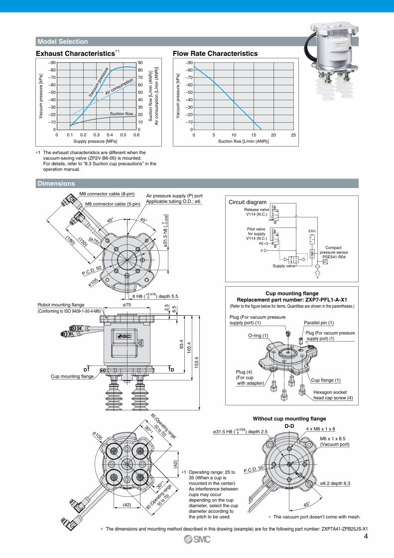
Dimensions
Model Selection
90
80
70
60
50
40
30
20
10
0
−90
−80
−70
−60
−50
−40
−30
−20
−10
00 0.1 0.2 0.3 0.4 0.5 0.6
Vac
uum
pre
ssur
e [k
Pa]
Suc
tion
flow
[L/m
in (
AN
R)]
Air
cons
umpt
ion
[L/m
in (
AN
R)]
Supply pressure [MPa]
Vacu
um p
ress
ure
Air consumption
Suction flow
−90
−80
−70
−60
−50
−40
−30
−20
−10
0
Vac
uum
pre
ssur
e [k
Pa]
Suction flow [L/min (ANR)]
0 5 10 15 20 25
Cup mounting flangeReplacement part number: ZXP7-PFL1-A-X1
(Refer to the figure below for items. Quantities are shown in the parentheses.)
O-ring (1)
Cup flange (1)
Hexagon socket head cap screw (4)
Plug (4)(For cup with adapter)
Parallel pin (1)Plug (For vacuum pressure supply port) (1)
Plug (For vacuum pressure supply port) (1)
Supply valve
Pilot valve for supply
V114 (N.C.)
Release valveV114 (N.C.)
P
P
PE
EXH.
V
Compact pressure sensor
PSE541-R04
Circuit diagram
∗ The dimensions and mounting method described in this drawing (example) are for the following part number: ZXP7A41-ZPB25JS-X1
∗1 Operating range: 25 to 35 (When a cup is mounted in the center)As interference between cups may occur depending on the cup diameter, select the cup diameter according to the pitch to be used. ∗ The vacuum port doesn’t come with mesh.
∗1 The exhaust characteristics are different when the vacuum-saving valve (ZP2V-B6-05) is mounted.For details, refer to “8.3 Suction cup precautions” in the operation manual.
Exhaust Characteristics∗1 Flow Rate Characteristics
4
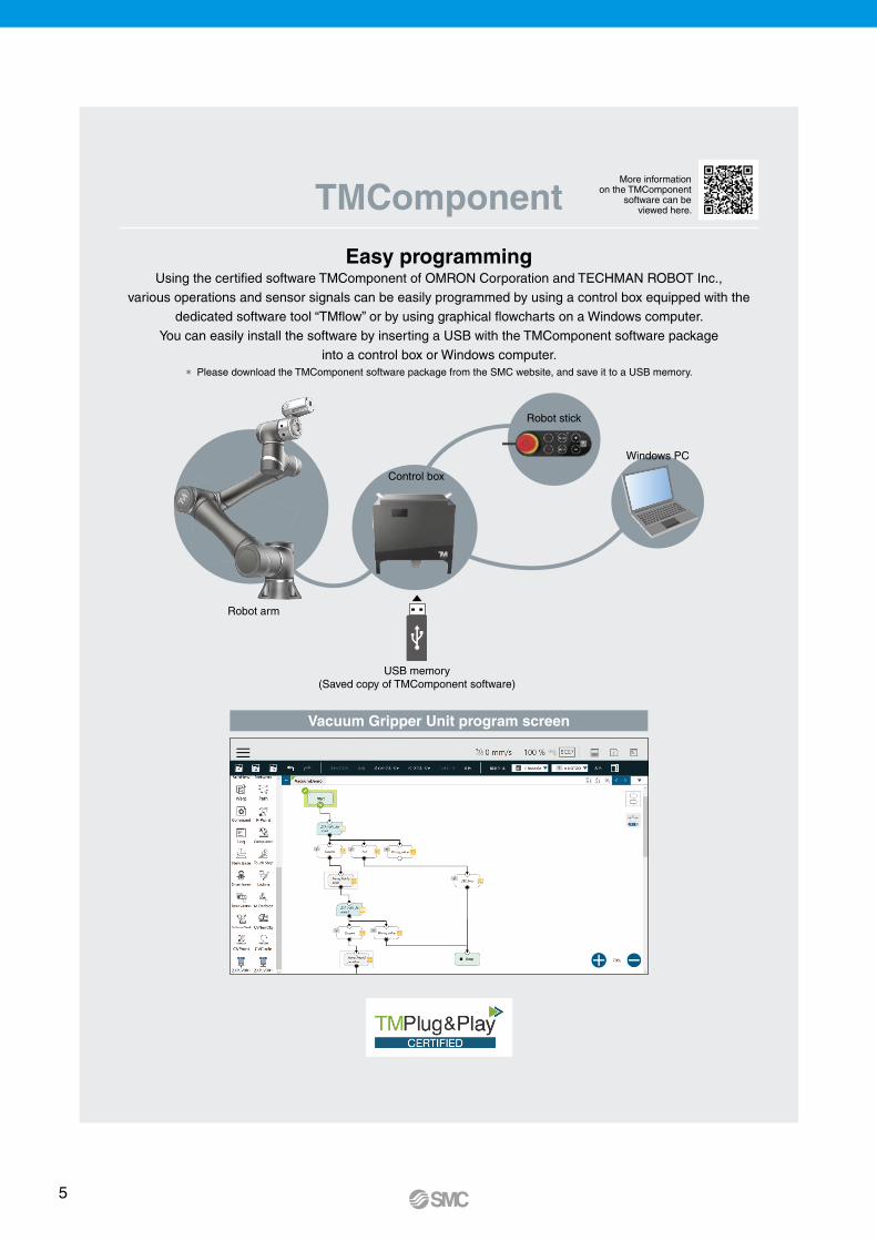
Easy programmingUsing the certified software TMComponent of OMRON Corporation and TECHMAN ROBOT Inc.,
various operations and sensor signals can be easily programmed by using a control box equipped with the dedicated software tool “TMflow” or by using graphical flowcharts on a Windows computer.
You can easily install the software by inserting a USB with the TMComponent software package into a control box or Windows computer.
* Please download the TMComponent software package from the SMC website, and save it to a USB memory.
TMComponent
Vacuum Gripper Unit program screen
Robot arm
Control box
Robot stick
Windows PC
USB memory(Saved copy of TMComponent software)
More informationon the TMComponent
software can beviewed here.
https://www.smcworld.com/products/en/get.do?type=GUIDE&id=ZXP-X-OMRON-E&_qr=catalog
5
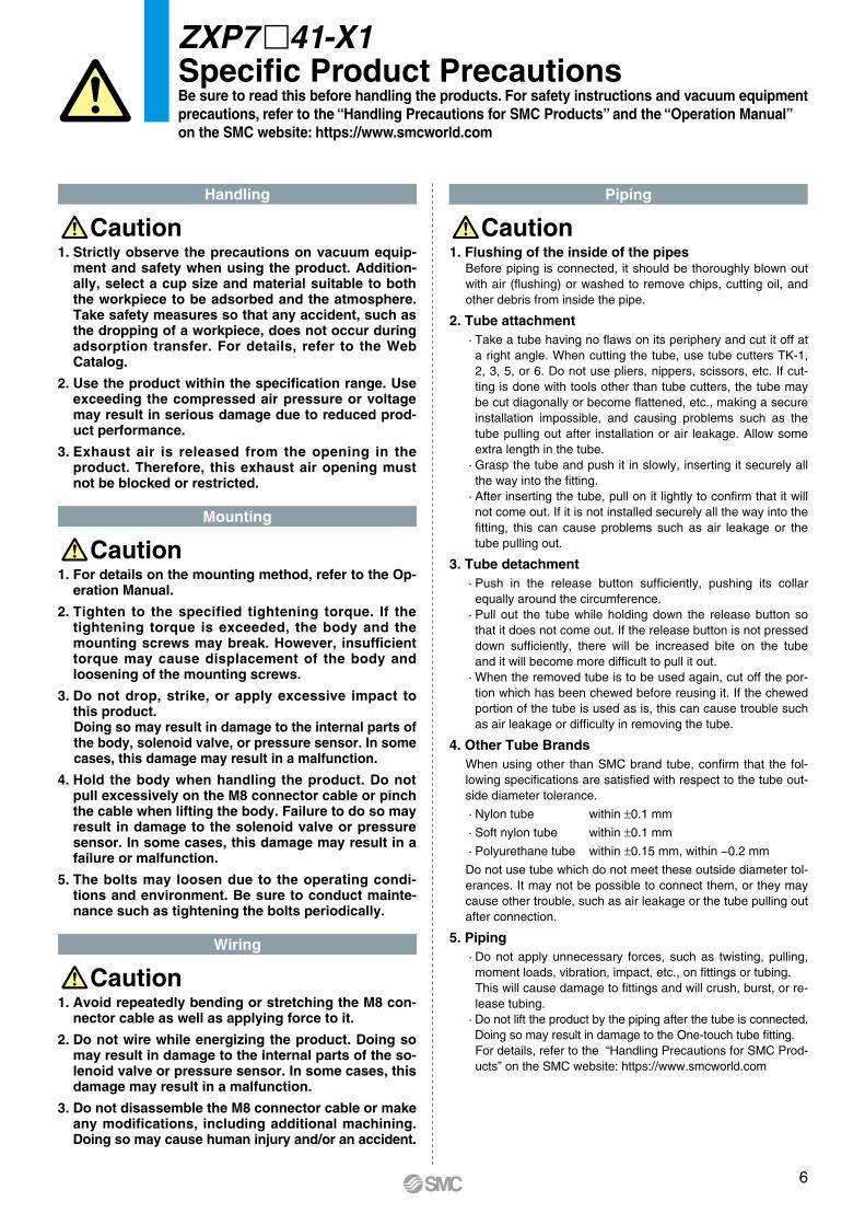
1. Flushing of the inside of the pipesBefore piping is connected, it should be thoroughly blown out with air (flushing) or washed to remove chips, cutting oil, and other debris from inside the pipe.
2. Tube attachment· Take a tube having no flaws on its periphery and cut it off at a right angle. When cutting the tube, use tube cutters TK-1, 2, 3, 5, or 6. Do not use pliers, nippers, scissors, etc. If cut-ting is done with tools other than tube cutters, the tube may be cut diagonally or become flattened, etc., making a secure installation impossible, and causing problems such as the tube pulling out after installation or air leakage. Allow some extra length in the tube.
· Grasp the tube and push it in slowly, inserting it securely all the way into the fitting.
· After inserting the tube, pull on it lightly to confirm that it will not come out. If it is not installed securely all the way into the fitting, this can cause problems such as air leakage or the tube pulling out.
3. Tube detachment· Push in the release button sufficiently, pushing its collar equally around the circumference.
· Pull out the tube while holding down the release button so that it does not come out. If the release button is not pressed down sufficiently, there will be increased bite on the tube and it will become more difficult to pull it out.
· When the removed tube is to be used again, cut off the por-tion which has been chewed before reusing it. If the chewed portion of the tube is used as is, this can cause trouble such as air leakage or difficulty in removing the tube.
4. Other Tube BrandsWhen using other than SMC brand tube, confirm that the fol-lowing specifications are satisfied with respect to the tube out-side diameter tolerance.
· Nylon tube within ±0.1 mm
· Soft nylon tube within ±0.1 mm
· Polyurethane tube within ±0.15 mm, within −0.2 mm
Do not use tube which do not meet these outside diameter tol-erances. It may not be possible to connect them, or they may cause other trouble, such as air leakage or the tube pulling out after connection.
5. Piping· Do not apply unnecessary forces, such as twisting, pulling, moment loads, vibration, impact, etc., on fittings or tubing.This will cause damage to fittings and will crush, burst, or re-lease tubing.
· Do not lift the product by the piping after the tube is connected. Doing so may result in damage to the One-touch tube fitting.For details, refer to the “Handling Precautions for SMC Prod-ucts” on the SMC website: https://www.smcworld.com
PipingHandling
Mounting
Wiring
1. �Strictly observe the precautions on vacuum equip-ment and safety when using the product. Addition-ally, select a cup size and material suitable to both the workpiece to be adsorbed and the atmosphere. Take safety measures so that any accident, such as the dropping of a workpiece, does not occur during adsorption transfer. For details, refer to the Web Catalog.
2. Use the product within the specification range. Use exceeding the compressed air pressure or voltage may result in serious damage due to reduced prod-uct performance.
3. Exhaust air is released from the opening in the product. Therefore, this exhaust air opening must not be blocked or restricted.
1. �For details on the mounting method, refer to the Op-eration Manual.
2. �Tighten to the specified tightening torque. If the tightening torque is exceeded, the body and the mounting screws may break. However, insufficient torque may cause displacement of the body and loosening of the mounting screws.
3. �Do not drop, strike, or apply excessive impact to this product. Doing so may result in damage to the internal parts of the body, solenoid valve, or pressure sensor. In some cases, this damage may result in a malfunction.
4. �Hold the body when handling the product. Do not pull excessively on the M8 connector cable or pinch the cable when lifting the body. Failure to do so may result in damage to the solenoid valve or pressure sensor. In some cases, this damage may result in a failure or malfunction.
5. �The bolts may loosen due to the operating condi-tions and environment. Be sure to conduct mainte-nance such as tightening the bolts periodically.
1. �Avoid repeatedly bending or stretching the M8 con-nector cable as well as applying force to it.
2. �Do not wire while energizing the product. Doing so may result in damage to the internal parts of the so-lenoid valve or pressure sensor. In some cases, this damage may result in a malfunction.
3. �Do not disassemble the M8 connector cable or make any modifications, including additional machining. Doing so may cause human injury and/or an accident.
Caution Caution
Caution
Caution
ZXP7 m41-X1Specific Product PrecautionsBe sure to read this before handling the products. For safety instructions and vacuum equipmentprecautions, refer to the “Handling Precautions for SMC Products” and the “Operation Manual” on the SMC website: https://www.smcworld.com
6
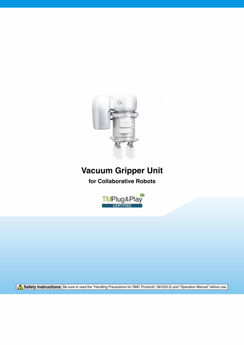
Vacuum Gripper Unitfor Collaborative Robots
Safety Instructions Be sure to read the “Handling Precautions for SMC Products” (M-E03-3) and “Operation Manual” before use.