vacuum insulation panel properties and building applications€¦ · · 2017-11-21vacuum...
TRANSCRIPT

HiPTI - High Performance Thermal Insulation IEA/ECBCS Annex 39
Vacuum Insulation Panel Properties and Building Applications
Summary
Editor Markus Erb
Operating Agent Dr.Eicher+Pauli AG, Switzerland
Contributions
ZAE-Bayern, Germany Ulrich Heinemann, Hubert Schwab
EMPA, Switzerland Hans Simmler, Samuel Brunner, Karim Ghazi, Reto Bundi
NRC, Canada Kumar Kumaran, Phalguni Mukhopadhyaya
CSTB, France Daniel Quénard, Hébert Sallée
Fraunhofer IVV, Germany Klaus Noller, Esra Kücükpinar-Niarchos, Cornelia Stramm
TU-Delft, Netherlands Martin Tenpierik, Hans Cauberg
FHBB, Switzerland Armin Binz, Gregor Steinke, André Moosmann
December 2005

High Performance Thermal Insulation Summary IEA/ECBCS Annex 39
Impressum
IEA/ECBCS Annex 39 The work presented here is a contribution to Annex 39 of IEA/ECBCS-Implementing Agreement.
Title Vacuum Insulation - Panel Properties and Building Applications
Editor Markus Erb Operating Agent Dr.Eicher+Pauli AG, Switzerland December 2005

High Performance Thermal Insulation Summary IEA/ECBCS Annex 39
Page I
Abstract
Vacuum insulation panels (VIP) were already developed some time ago for use in appliances such as refrigerators and deep-freezers. Their insulation performance is a factor of five to ten times better than that of conventional insulation. Used in buildings they enable thin, highly insulating constructions to be realized for walls, roofs and floors.
The motivation for examining the applicability of high performance thermal insulation in buildings (i.e. evacuated insulation in the form of vacuum insulation panels) came from the difficulties involved in renovation – namely severe space limitations and therefore technical constraints, as well as from aesthetic considerations.
Vacuum Insulation Panels The thermal resistance of evacuated insulation is a factor of five to ten better than conven-tional insulation of the same thickness. Vacuum insulation panels (VIP) in general are flat elements consisting of an open porous (and therefore evacuation-capable) core material which has to withstand the external load caused by atmospheric pressure, as well as a sufficiently gas-tight envelope to maintain the required quality of the vacuum.
Nano-structured materials have been found to require the least quality of vacuum, which has to be achieved and to be maintained. In panels basically made of pressed fumed silica, the contribution of the gas to the total heat transfer is virtually eliminated even at an internal gas pressure of a few hundred Pascals. The requirements on the gas-tightness of the envelope are also relatively moderate for these extremely fine-structured core materials – the largest pores are in the order of 100 nanometres. Thin laminated metal foils and special high-barrier metallized laminates consisting mainly of polymers are therefore used for the envelope. This report focuses especially on this type of VIP, which combines relatively simple and flexible production methods (and is therefore currently the least expensive alternative) with an ser-vice life of 30 to 50 years, limited by air permeation into the panels. Even if the vacuum failed completely, the thermal resistivity of this filler material is twice as efficient as that of any standard insulation material.
Investigations have been performed individually on the core materials and laminates de-signed for the envelope as well as manufactured VIP.
Building Applications The introduction of such a novel insulation system in the building trade, however, is ham-pered by many open questions and risks. The work illustrates a wide selection of reports from practice, shows how the building trade deals with this new insulation system today, the experience gained and the conclusions drawn there from. As well as presenting recommen-dations for the practical use of VIP, the report is also able to answer questions regarding the effective insulation values to be expected with today's VIP.

High Performance Thermal Insulation Summary IEA/ECBCS Annex 39
Page II
Content
ABSTRACT I
CONTENT II
1 INTRODUCTION 1
2 IEA/ECBCS ANNEX 39 2
3 VACUUM INSULATION PANELS 4
3.1 Core 4
3.2 Envelope 7
3.3 Aging 9
4 BUILDING APPLICATIONS 14
4.1 Thermal bridging 14
4.2 VIP in practical use 18
4.3 Use of VIP – Recommendations 22
5 OUTLOOK 24
REFERENCES 26

High Performance Thermal Insulation Summary IEA/ECBCS Annex 39
Page 1
1 Introduction
The motivation for examining the applicability of high performance thermal insulation in buildings (i.e. evacuated insulation in the form of vacuum insulation panels) came from the difficulties involved in renovation – namely severe space limitations and therefore technical constraints, as well as from aesthetic considerations.
The following numbers give an impression on potential impact vacuum insulation could have on energy consumption:
In 1997, about 25% of the energy consumption in the EU came from room heating.
In 1995, there were roughly 150 million dwellings in the EU-15, 32% of this stock was built prior to 1945, 40% between 1945 and 1975 and 28% between 1975 and 1995.
Table 1: Energy consumption of buildings in Europe. (Source: Directive of the European Parliament And The Council on the energy performance of buildings.)
Residential Sector [%] Commercial [%] Space Heating 57 Space Heating 52Water Heating 25 Water Heating 9 Electric Appliances 11 Lighting 14 Cooking 7 Office Equipment 16 Cooking 5 Cooling 4

High Performance Thermal Insulation Summary IEA/ECBCS Annex 39
Page 2
2 IEA/ECBCS Annex 39
Germany and Switzerland were the first two countries supporting R&D activities with the aim of introducing VIP-technology to the building industry. In 2000 Switzerland decided to launch the topic on an international level. This happened in the frame of the IEA (International Energy Agency) Implementing Agreement called ECBCS (Energy Conservation in Buildings and Community Systems). Implementing Agreements are a kind of international networks of national representatives with the aim of coordinating applied research in the field of energy.
Annex 39 was the 39th research program of ECBCS. It was officially adopted by the Execu-tive Committee of ECBCS in November 2000 and started with an international conference in January 2001.
Since the topic was new to the research community, it was quite difficult to set up a work plan with the participating institutes. One problem for instance was the lack of standard methods to study VIP. But finally a work plan with two main fields of activity (subtasks) was developed:
Subtask A: Panels
Existing products, mainly VIP, were analysed and their properties optimised in the way, that they meet the requirements of the systems in which they are applied.
Measurement standards concerning product declaration and quality monitoring procedures were developed.
Subtask B: Applications
Part 1: Application and system development
Companies developing VIP-systems for the building envelope and HVAC components were supported. The support consisted in informing potential companies about VIP, forming suit-able groups for each development project, providing theoretical and practical information (simulation and testing of systems).
Part 2: Demonstration and information dissemination
Demonstration projects were realized together with architects and building owners.
Lessons learned from the demonstration projects were collected and used for further im-provement of the materials and systems.
Information material was distributed to increase the interest of construction companies and clients.

High Performance Thermal Insulation Summary IEA/ECBCS Annex 39
Page 3
Participating institutes
Annex 39 Name e-mail Contribution
Dr.Eicher+Pauli AG Switzerland
Markus Erb [email protected] Operating Agent
Introduction
Subtask A
ZAE-Bayern Germany
Ulrich Heinemann
Hubert Schwab
Leader Subtask A
Core material, Panel, Quality assurance , Outlook
EMPA Switzerland
Hans Simmler
Samuel Brunner
Panel
NRC/IRC Canada
Kumar Kumaran
Phalguni Muk-hopadhyaya
Core material, Envelope
CSTB* France
Daniel Quénard
Hébert Sallée
Core material
Fraunhofer IVV Germany
Klaus Noller
Esra Kücükpinar-Niarchos
Cornelia Stramm
Envelope
TU Delft Netherlands
Martin Tenpierik
Hans Cauberg
Panel
Subtask B Name e-mail Contribution
FHBB Switzerland
Armin Binz
André Moosmann
Gregor Steinke
Leader Subtask B
Report editor, Practice Report I, Recommendations, Economics
EMPA Switzerland
Karim Ghazi
Reto Bundi
Thermal bridges
ZAE-Bayern Germany
Ulrich Heinemann
Hubert Schwab
Practice Report II
TU Delft Netherlands
Hans Cauberg
Martin Tenpierik
Case studies
KTH Stockholm Sweden
Gudni Johannesson
Thomas Thorsell
Edge effect (stainless steel)

High Performance Thermal Insulation Summary IEA/ECBCS Annex 39
Page 4
3 Vacuum Insulation Panels
Vacuum insulation panels (VIP) in general are flat elements consisting of an open porous (and therefore evacuation-capable) core material which has to withstand the external load caused by atmospheric pressure, as well as a sufficiently gas-tight envelope to maintain the required quality of the vacuum.
Figure 1: Components of a VIP. The core-bag provides mechanical stability for handling and protects the welding area from being polluted by core-powder. (foto: va-Q-tec).
3.1 Core
Nano-structured materials have been found to require the least quality of vacuum, which has to be achieved and to be maintained. In panels basically made of pressed fumed silica, the contribution of the gas to the total heat transfer is virtually eliminated even at an internal gas pressure of a few hundred Pascal.
pressed silica core with opacifier
multi-layer envelope film
core-bag
welded seam
High Performance Thermal Insulation Summary IEA/ECBCS Annex 39
Page 5
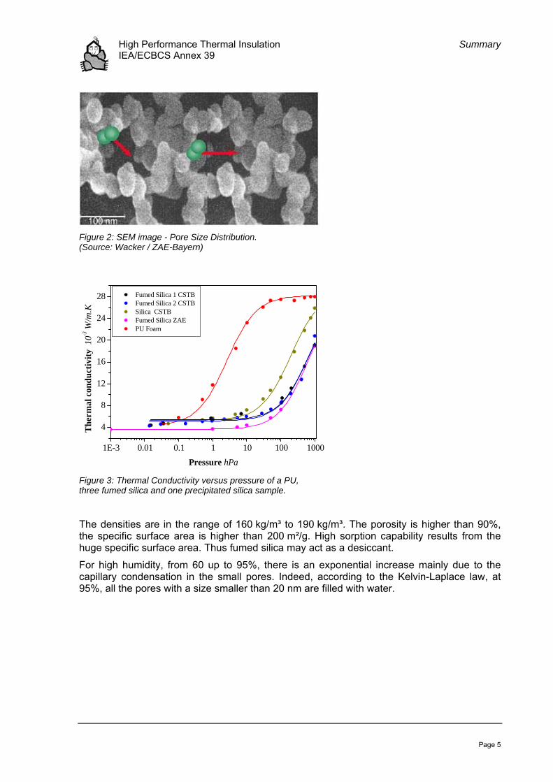
Figure 2: SEM image - Pore Size Distribution. (Source: Wacker / ZAE-Bayern)
1E-3 0.01 0.1 1 10 100 1000
4
8
12
16
20
24
28 Fumed Silica 1 CSTB Fumed Silica 2 CSTB Silica CSTB Fumed Silica ZAE PU Foam
The
rmal
con
duct
ivity
10-3
W/m
.K
Pressure hPa Figure 3: Thermal Conductivity versus pressure of a PU, three fumed silica and one precipitated silica sample.
The densities are in the range of 160 kg/m³ to 190 kg/m³. The porosity is higher than 90%, the specific surface area is higher than 200 m²/g. High sorption capability results from the huge specific surface area. Thus fumed silica may act as a desiccant.
For high humidity, from 60 up to 95%, there is an exponential increase mainly due to the capillary condensation in the small pores. Indeed, according to the Kelvin-Laplace law, at 95%, all the pores with a size smaller than 20 nm are filled with water.

High Performance Thermal Insulation Summary IEA/ECBCS Annex 39
Page 6
0.2 0.3 0.4 0.5 0.6 0.7 0.8 0.9 1.0
Rel. Humidity at 23°C [-]
Adsorption isotherm for fumed silica
0
5
10
15
20
25
30
0 5 10 15 20 25
H2O partial pressure [mbar]
Wat
er c
onte
nt [%
]
Saturation water vapor pressureMagnus Equation
0
50
100
150
200
250
300
0 10 20 30 40 50 60 70
Temperature [°C]
Vapo
r pr
essu
re [m
bar]
Figure 4: Left: Adsorption isotherm of fumed silica (fitted curve, based on data of three laboratories). Right: Partial water vapor pressure of saturated air.
At a low gas pressure (1 mbar) and at room temperature the total thermal conductivity of the core material is about 0.004 W/(m·K) - 0.001 W/(m·K) from infrared radiative heat transfer and 0.003 W/(m·K) due to heat conduction via the solid skeleton. The thermal conductivity increases with the internal gas pressure to about 0.020 W/(m·K) at ambient pressure.
0
0,1
0,2
0,3
0,4
0,5
0 2 4 6 8 10
water content [mass-%]
heat
tran
smis
sion
co
effic
ient
[
W/(m
2 K)]
Figure 5: Measured heat transfer coefficient versus the water content for a 20 mm thick VIP. Mean temperature was 10°C.
At 10°C the impact of water content on the thermal conductivity was found to be linear with an increase of about 0.0005 W/(m·K) per mass-% of adsorbed water.
mass%KmmW5.0
Xw −≈
∂∂λ
(1)
Starting with an approximate initial thermal conductivity of about 4⋅10−3 W/(m⋅K) for the dry core, a value of about 6⋅10−3 W/(m⋅K) results for moisture equilibrium at 50% RH.
The influence of other atmospheric gases on the thermal conductivity may be estimated by the following linear relation between gas pressure and thermal conductivity:

High Performance Thermal Insulation Summary IEA/ECBCS Annex 39
Page 7
mbarKmmW035.0
p≈
∂∂λ in the range up to 100 mbar
(2)
λ: thermal conductivity, W/(m·K)
p: “dry gas” pressure in the pores, mbar
Thus a dry gas pressure increment of 30 mbar corresponds to a thermal conductivity in-crease of about 1⋅10−3 W/(m⋅K).
3.2 Envelope
The most critical component of a Vacuum Insulation Panel (VIP) is the envelope, which is responsible for the maintenance of the vacuum inside the panel. Normally polymer laminates are used which contain metallized polymers or aluminium foils as barrier layer.
Figure 6: Permeation mechanism (schematic) through a laminate containing two homogenous polymers.
As with all polymeric films, the transmission rate for water vapour (WVTR) for these lami-nates was found to be several orders of magnitude greater than those for oxygen (OTR) or nitrogen: The units used for WVTR is g/(m²·d) and for OTR cm³(STP)/(m²·d) and today prod-ucts do have WVTR and OTR in the same range but 1 g H2O equals 1’244 cm3.

High Performance Thermal Insulation Summary IEA/ECBCS Annex 39
Page 8
Table 1: Laminate transmission rates according to manufacturer’s specifications for the tested laminates. PET=PolyEthylenTerephtalate, PE=PolyEthylen, PP=PolyPropylen, LD=LowDensity, met=Al-layer 30 to 80 nm thick.
Name Laminate composition OTR [cm³(STP)/(m²·d)]
WVTR
[g/(m²·d)]
AF
12 µm PET / 8 µm Al / 100 µm PE-LD < 0.0005
(25°C / 50% RH)
< 0.005
(20°C / 50% RH)
MF1 15 µm PPmet / 12 µm PETmet / 50 µm PE 0.07
(23°C / 50% RH)
0.1
(38°C / 90% RH)
MF2 20 µm PETmet / 20 µm PETmet / 25 µm PE 0.00062
(23°C / 75% RH)
0.005
(23°C / 75% RH)
12 µm PET / 8 µm Al / 100 µm PE-LD
15 µm PPmet / 12 µm PETmet / 50
µm PE
20 µm PETmet / 20 µm PETmet / 25
µm PE
Water vapor and oxygen transmission rates (producer declaration)
0.000
0.001
0.010
0.100
1.000
AF1 < MF1 MF2
OTR [cm³(STP)/(m²·d)]WVTR [g/(m²·d)]
Figure 7: Transmission rates (producer declaration) of an aluminium foil based film (AF) and two polymer based metallized films (MF).
Measuring extremely low permeation rates is challenging and very time-consuming. A fast measurement tool was developed to derive water vapour transmission rates from helium transmission measurements. The effects of corners and edges on water vapour and on oxygen transmission rates were also determined.

High Performance Thermal Insulation Summary IEA/ECBCS Annex 39
Page 9
3.3 Aging
The thermal conductivity λcop of a well evacuated dry VIP with a fumed silica core is typically about 0.004 W/(m·K) after production. As the low internal pressure is not in equilibrium with the environment, pressure gradients are present that act as driving forces for the intrusion of atmospheric gas (essentially N2, O2 and H2O) and by this the thermal performance of VIP is impaired in two ways:
- increasing internal gas pressure and
- increase in the internal water content.
3.3.1 Aging vs. durability
In this context one might distinguish between aging and durability in the following sense: aging is a continuous process of performance degradation due to (normally) slow permeation of atmospheric gas molecules through the imperfect barrier, resulting in a non-reversible pressure increase and moisture accumulation in the hygroscopic VIP core. In contrast, durability is the ability of a VIP to withstand chemical or mechanical impacts that would cause failure of the barrier envelope, thus changing the internal low-pressure state within a short time by severe damage or rupture of the barrier. Regarding durability the risks for VIP in suitable building applications occur mainly before or during installation. A certain failure rate is present at the production plant, caused by material imperfections or processing errors. This type of failure can be largely avoided by quality control as well as by storing the panels during a specified time under defined conditions and checking them before they are shipped. It can be stated that the number of damaged or defective panels leaving the production plant was substantially reduced in the last few years. The figure is roughly assumed to be less than one percent. More frequent failures occur during transportation and handling of the panels until they are safely installed. Without protection the envelope is highly sensitive to mechanical impact, especially to point loads e.g. by sand grains, bricks or stone fragments, or other sharp objects including tools and corners of other panels. Once installed work-manlike, failure risks are observed to be low.
3.3.2 Measurement methods
Measurements on panels stored in different climatic conditions gave detailed information on permeation rates for air and water vapour as a function of temperature and humidity includ-ing all the effects of edges, corners and processing.
As a very accurate method to measure the internal pressure of panels a depressurization based method has been successfully applied by ZAE-Bayern, EMPA and NRC: the pressure around a VIP specimen is continuously reduced in a vacuum chamber. If the pressure in the chamber diminishes to below the VIP pressure, the VIP envelope lifts off the core surface. This can be recorded visually or by using photo electric sensors.

High Performance Thermal Insulation Summary IEA/ECBCS Annex 39
Page 10
3.3.3 Results
3.3.3.1 Overview
The laminate with only one metallized layer was clearly proved not to fulfil the requirements. Acceptable pressure increases of about 1 mbar per year can be expected for VIP with an Al-foil and for laminates with three metallized layers.
Table 2: Area (subscript A) and perimeter (subscript L) related transmission characteristics of VIP with metallized polymer laminates (MF) for 23°C, 50% RH and 1 bar. For the MF1 and MF2 samples, an WVTRL value (edge effect) could not be determined since the panels were too small.
Barrier type WVTRA, g/(m2 d) WVTRL, g/(m d) ATRA, cm3/(m2 d) ATRL, cm3/(m d) MF1 0.0233 - 0.0160 0.0080
MF2 0.0057 - - 0.0039
MF3 0.0030 0.0008 0.0034 0.0091
MF4 0.0048 0.0006 0.0088 0.0018
3.3.3.2 Air-transmission - edge-effect
The significant contribution of air permeation through the edge-area of the VIP postulates that panels may not be too small in size, (i.e. larger than 50 cm x 50 cm).
Pressure increaseAir permeation
0
1
2
3
4
0.0 0.2 0.4 0.6 0.8 1.0
panel area [m2]
dp [m
bar/y
r]
MF 1
MF 2
MF 3
MF 4
Figure 8: Edge effect on internal pressure increase by air permeation through four different metallized films (rectangular panel).
3.3.3.3 Water vapour transmission
Water vapour uptake in the threefold metallized film was found to be mainly dependent on the size of the panel surface - much smaller edge effect than for air permeation, whereas the panels with Al-film absorbed water vapour at a much lower rate, and this occurred mostly through the edges and seams.

High Performance Thermal Insulation Summary IEA/ECBCS Annex 39
Page 11
Weight increaseWater vapour permeation
0.0
0.1
0.2
0.3
0.4
0.5
0.6
0.0 0.2 0.4 0.6 0.8 1.0
panel area [m2]
Xw [%
-mas
s/yr
]
MF1
MF2
MF3
MF4
Figure 9: Edge effect on weight increase by water vapour permeation through four different metallized films. For the MF1 and MF2 samples, an edge effect could not be determined since the panels were too small (rectangular panel).
3.3.3.4 Climatic dependencies of transmission rates
The dependence of air transmission rates on temperature can be described by the Arrhenius law with activation energies that are in the range of 25 to 40 kJ/mol.
Water vapour transmission rates are proportional to the differences in the partial pressures inside and outside, a significant explicit dependence on temperature could not be observed.
Pressure increase vs. temperaturePanel format 20 x 20 x 1 cm3 (H2O 14 mbar)
05
101520
2530
35
40
20 30 40 50 60 70Temperature [°C]
dp [m
bar/y
r]
AFMF1MF2
Weight increase vs. H2O partial pressurePanel format 25 x 25 x 2 cm3
30°C65°C
80°C
23°C
0%
5%
10%
15%
20%
25%
0 50 100 150 200 250 300 350 400H2O partial pressure [mbar]
dm [M
-%/a
]
Figure 10: Internal pressure increase caused by dry air (left) and water vapour (right) permeation. The meas-urements were done at room temperature after cooling down the samples for some hours.

High Performance Thermal Insulation Summary IEA/ECBCS Annex 39
Page 12
3.3.3.5 VIP service life prediction
With the following equation the increase in the thermal conductivity of the VIP as a function of time can be calculated:
( )( )
( )tXb
tpp1
t w
air
air,2/1
air,freeevac ⋅+
++=
λλλ .
(3)
The following values apply to VIP with fumed silica kernels of density ρVIP ≈ 170 kg/m³, λevac = 4·10−3 W/(m·K), p1/2,air ≈ p1/2,N2= 600 mbar, λair = 25·10−3 W/(m·K) at 10°C and b = 0.5·10−3 W/(m·K)/%-mass at a mean temperature of 10°C. From the sorption isotherm k = 0.08%-mass per percent of relative humidity follows.
With the transmission characteristics of a certain laminate, pair(t) and XW(t) can be obtained and λ(t) calculated, as shown for MF2 in the figure below.
0.0
1.0
2.0
3.0
4.0
5.0
6.0
7.0
0 5 10 15 20 25Zeit [y]
tota
l the
rmal
co
nduc
tivity
[10-3
W/(m
K)]
0.0
1.0
2.0
3.0
4.0
5.0
6.0
7.0
incr
ease
in th
erm
al
cond
uctiv
ity [1
0-3 W
/(mK
)]
total for (50 x 50 x 1) cm³total for (100 x 100 x 2) cm³increase by humidity for (50 x 50 x 1) cm³increase by humidity for (100 x 100 x 2) cm³increase by air for (50 x 50 x 1) cm³increase by air for 100 x 100 x 2 cm³
film MF2
Figure 11: Total thermal conductivity as a function of time (upper part, left ordinate) and increases in air-related and humidity-related thermal conductivity (lower part, right ordinate) of VIP with film MF2 for different panel sizes.
3.3.4 Conclusions
If a time span of 25 years and typical environmental conditions (23 to 25°C and ambient vapour pressure) are taken as a basis for the long-term performance it can be concluded that the pressure increase will be rather linear over the whole period, whereas the moisture

High Performance Thermal Insulation Summary IEA/ECBCS Annex 39
Page 13
content could approach the saturation range (about 4%-mass) within this time period. Mois-ture equilibrium under normal conditions is basically acceptable, but must be accounted for by a respective increment on the initial thermal conductivity.
Maximum values (approximate) for VIP with actual multi-layer metallized polymer laminate barriers, measured or calculated from laboratory based aging experiments, are given in the table below. Applying known relations for the pressure and moisture impact on the thermal conductivity, maximum values for the thermal conductivity after 25 years are given in the table as well. These values are thought to be on the safe side in applications with VIP sur-face temperatures and vapour pressures in the range of ambient or indoor air.
Table 3: Aging characteristics for SiO2-VIP with polymer based multiple metallized barrier (safe values).
50 x 50 x 2 cm3 100 x 100 x 2 cm3
Pressure increase [mbar/yr] < 2.0 < 1.0
Moisture accumulation (initial) [%-mass/yr] < 0.2 < 0.2
Thermal conductivity λcop (25 yr) [W/(m·K)] < 0.008 < 0.007
3.3.5 Design values
From the results of the aging studies, design values of the thermal conductivity for the cen-ter-of-panel (λcop) can be derived.
Table 4: Swiss design values (safe values) of Center-of-panel thermal conductivities (λcop) for aluminium and polymer based multiple metallized barrier envelopes.
Swiss center-of-panel conductivity values λcop
AF: aluminium foil films [W/(m·K)] 0.006
MF: metallized polymer films [W/(m·K)] 0.008
In Switzerland a safety increment of 0.004 W/(m·K) is put on the “ideal” initial thermal con-ductivity value of 0.004 W/(m·K) for VIP with metallized polymer barrier. One part is due to the non-negligible moisture accumulation, which may be around 4%-mass in the long term, corresponding to a thermal conductivity increment of about 0.002 W/(m·K). In addition, a dry air pressure increase of 50 mbar is accounted for, roughly corresponding to another 0.002 W/(m·K) increment. Half increments are taken for VIP with metal foil based barrier. These figures are thought to be on the safe side with respect to both pressure increase and mois-ture accumulation over a time span of 25 years. It should be noted that this is a preliminary approach. If clearly better barrier quality is proven and proper initial conditions (low pressure, low moisture content) are guaranteed by the manufacturer, lower (individual) design values may be considered by the Swiss thermal insulation standardisation committee.

High Performance Thermal Insulation Summary IEA/ECBCS Annex 39
Page 14
4 Building Applications
The core part of the Subtask B report consists of practice reports, showing actual examples where vacuum insulation panels (VIP) have been used, and discussing special issues and open questions. A wide range of built examples, all using VIP, such as floor and ceiling constructions, terrace insulation, non-loadbearing sandwich elements, parapet insulation, prefabricated façade elements etc. form a rich basis of experience for interested planners and experts as well as manufacturers in search of new products with integrated VIP. Fur-thermore, the report states the actual knowledge on reliability, thermal bridge effect of the panel envelopes, i.e. the resulting thermal resistance of VIP, and recommended construc-tions with VIP.
4.1 Thermal bridging
Three different basic levels of thermal bridging can be distinguished:
- thermal bridging due to the thin film high barrier enveloping the core material
- thermal bridging due to the small air gap between two adjacent panels
- thermal bridging due to constructional irregularities
Figure 12: Schematic representation of a cold bridge caused by the VIP envelope.
Due to thermal bridging the effective or overall thermal conductivity, λeff, of the vacuum insulation panel is higher than the ideal centre-of-panel thermal conductivity λcop. The amount of this thermal bridge effect is also affected by the thermal properties material layers immedi-ately surrounding the VIP. The effective thermal conductivity of a VIP takes all non-homogeneities, originating from the product itself as well as from the joint between adjacent VIP into account. With other words, the effective thermal conductivity of a VIP represents the conductivity of a homogeneous material with equivalent thermal behaviour. By means of measurements carried out in a guarded hot plate apparatus on VIP samples of three different thicknesses and two different sizes, the effective thermal conductivity, i.e. the linear thermal transmittance ΨVIP of the VIP themselves has been determined.

High Performance Thermal Insulation Summary IEA/ECBCS Annex 39
Page 15
This effective thermal conductivity can be calculated as
λeff = λcop +ΨVIP · d · p / A (4)
λcop centre-of-panel thermal conductivity [W/(m·K)]
d thickness of the VIP (in the heat flux direction) [m]
A surface of the VIP (perpendicular to the heat flux direction) [m2]
p perimeter of the surface A [m]
ΨVIP linear thermal transmittance [W/(m·K)]
4.1.1.1 Envelope materials
Effective thermal conductivities for different envelope materials have been measured and modeled. Assuming a panel size of 1.00 x 0.50 x 0.02 m3 results:
- 8 µm aluminium foil: λcop 6·10-3 W/(m·K), Ψ 0.033 W/(m·K) → λeff 10.0·10-3 W/(m·K)
- 50 µm stainless steel foil: λcop 6·10-3 W/(m·K), Ψ 0.026 W/(m·K) → λeff 9.1·10-3 W/(m·K)
- three layer metallized film: λcop 8·10-3 W/(m·K), Ψ 0.006 W/(m·K) → λeff 8.7·10-3 W/(m·K)
λeff for VIP with different envelope materials
0
5
10
15
20
25
30
35
0.0 0.5 1.0 1.5 2.0panel area [m2]
λef
f [m
W/(m
K)]
Three layer metallized film
50 micron stainless steel
8 micron aluminium
Figure 13: Thermal bridge effect of different envelope materials on overall conductivity (λeff) of a rectangular panel with center-of-panel conductivity (λcop) of 8•10-3 W/(m•K) for the metallized film and 6•10-3 W/(m•K) for the aluminium foil and the stainless steel envelope.

High Performance Thermal Insulation Summary IEA/ECBCS Annex 39
Page 16
4.1.1.2 Adjacent materials
As well as the properties of the core material and the envelope, the ΨVIP value is influenced by the material layers immediately surrounding the VIP. At the EMPA the influence of various surrounding materials has been investigated. The calculations were performed for a VIP (20 mm) with metallized enveloping laminate for the adjacent materials metal, glass, wood and insulation, in each case without an air gap between the VIP and with a 5 mm air gap between the panels. Here the design value of λcop for metallized films of 8•10-3 W/(m•K) was used.
Thermal bridging by adjacent materials
0.006
0.007
0.008
0.009
0.010
0.011
0.012
2 mm Steel(no gap)
5 mm Glass(no gap)
20 mm Wood(no gap)
5 mmInsulation (no
gap)
2 mm Steel(gap)
5 mm Glass(gap)
20 mm Wood(gap)
5 mmInsulation
(gap)
λ [W
/mK
]
d 50x100d 100x100center of panel ("aged" design value)
Figure 14: Thermal bridge edge effect of different adjacent materials on overall conductiv-ity (λeff) of a panel with MF-envelope and a center-of-panel conductivity of 8•10-3 W/(m•K). “d 100x100” is the increase for a panel of 100x100 cm2 compared to λcop and “d 50x100” is the increase for a panel of 50x100 cm2 compared to the lager format.
4.1.1.3 Façade panel constructions
With edge spacer constructions both component facings are mechanically jointed by means of a load transmitting edge spacer, while with the sandwich construction the component facings are adhered to a core material to form a structurally active sandwich.

High Performance Thermal Insulation Summary IEA/ECBCS Annex 39
Page 17
Figure 15: Different edge spacers. a.) aluminium spacer double-glazing; b.) sealant spacer; c.) reinforced non-metallic tape (0.15 mm); d.) optimised thermoplastic spacer (Henkel Tereson Thermoplastic Spacer); e.) polymer U-section.
For the calculations the following edge spacer materials were used:
Fumed silica based VIP (λcop = 0.008 W/(m·K))
- Edge spacer a: standard double-glazing aluminium edge spacer (λ = 225 W/(m·K)) polysulfide sealant (λ = 0.40 W/(m·K)) and silicon sealant (λ = 0.35 W/(m·K))
- Edge spacer b: butyl sealant (λ = 0.24 W/(m·K))
- Edge spacer c: non-metallic tape (λ ≈ 0.33 W/(m·K)); thickness ≈ 0.15 mm
- Edge spacer d: thermoplastic spacer (λ = 0.25 W/(m·K)) polysulfide (λ = 0.40 W/(m·K))
Thermal bridging by different spacer
0.000
0.005
0.010
0.015
0.020
0.025
0.030
0.035
AF MF AF MF AF MF AF MF
spacer a(aluminium)
spacer b (sealant) spacer c (non-metallic tape)
spacer d(thermoplastic)
λef
f [W
/mK
]
d Lambda.effLambda w/o spacer
Figure 16: Thermal bridge edge effect of different spacers in façade panel construc-tions. The usedVIP have metallized- (MF) or aluminium foil (AF) envelopes. The center-of-panel conductivity is 8•10-3 W/(m•K). The outside facing is 6 mm glass and the inside facing is 1.5 mm aluminium. “d Lambda.eff” is the increase for a panel of 100x100x2 cm3 compared to λcop.

High Performance Thermal Insulation Summary IEA/ECBCS Annex 39
Page 18
As can be seen as well, aluminium spacers (spacer a) are not suitable for façade panels with incorporated vacuum insulated panels, because a linear thermal transmittance, Ψ, of ap-proximately 0.30 (MF) to 0.34 (AF) leads to an increase in effective U-value for a panel of 1 x 1 m2 with 20 mm vacuum insulation panel from approximately 0.31 (MF) and 0.39 (AF) to 1.23 and 1.33 W/(m2·K). Better performances can be expected from the spacers b and d, while the best performance is calculated for the reinforced non-metallic tape (for λ cop = 0.008 W/(m·K) the U-value Ueff = 0.65 W/(m2·K) for a 20 mm vacuum insulation panel construction with an aluminium foil and Ueff = 0.44 W/(m2·K) for a 20 mm vacuum insulation panel construction with a metallized polymer film. This reinforced tape, however, might not adequately transmit forces, especially if wind suction is the main load to be transmitted. For sandwich panels, however, this edge spacer does not have to transmit loads and can thus be used for safety and protection against damage.
4.2 VIP in practical use
VIP are today mainly installed directly in the construction on site. By far the commonest use is the insulation of flat roof terraces with VIP. In the following table the 20 examples, which have been analysed and documented in [IEA 2005b] of VIP applications are shortly charac-terized.
Project City /
Country Building Application Place
New
.
Ren
ov.
Faç
ade
Cei
ling
Roo
f
Oth
er
ext
erio
r
inte
rior
Floor and ceiling insulation
Attachment to a single-family house
Zug
SWI
x x x
Interior and dormer window insulation
Refurbishment of property
Zürich
SWI
x x x x x x
Terrace insulation
Multifamily houses
Kerzers
SWI
x x x x

High Performance Thermal Insulation Summary IEA/ECBCS Annex 39
Page 19
Project City / Country
Building Application Place
New
.
Ren
ov.
Faç
ade
Cei
ling
Roo
f
Oth
er
ext
erio
r
inte
rior
Floor insulation in a cold and deep-freeze room
Conversion of a shop
Winter-thur
SWI
x x x
Non-load bearing wall sandwich elements
Single-family house
Land-schlacht
SWI
x x x
Parapet insulation in window element
Apartment conver-sion in a multifamily house
Basel
SWI
x x x
Façade insulation with prefabricated panels
Terraced houses
Binnin-gen
SWI
x x x
Façade insulation
Renovation of a semi-detached house
Nuern-berg
GER
x x x

High Performance Thermal Insulation Summary IEA/ECBCS Annex 39
Page 20
Project City / Country
Building Application Place
New
.
Ren
ov.
Faç
ade
Cei
ling
Roo
f
Oth
er
ext
erio
r
inte
rior
Insulation of outside walls, roof and door
A new semi-detached wooden house
Munich
GER
x x x x x
Insulation of the building envelope
Complete renewal of a terraced house
Munich
GER
x x x x x
Insulation of a wall heating system
Renovation of a former church
Wernfeld
GER
x x x x
Jamb-crossbar construction
Extension of the Hospital
Erlen-bach
GER
x x x
Integrated façade element with radiator
Test façade ZAE Bayern
Wuerz-burg
GER
x x x x
Insulated prefabri-cated concrete elements
Office building with an apartment
Ravens-burg
GER
x x x

High Performance Thermal Insulation Summary IEA/ECBCS Annex 39
Page 21
Project City / Country
Building Application Place
New
.
Ren
ov.
Faç
ade
Cei
ling
Roo
f
Oth
er
ext
erio
r
inte
rior
Façade insulation
Passive house
Ber-senbrueck
GER
x x x
Façade insulation with polystyrene-lined VIP
Terraced house
Trier
GER
x x x
Façade insulation
Refurbishment of an apartment and office block
Munich
GER
x x x
Floor insulation
Allgäu Energy and Environment Centre
Kempten
GER
x x x x
Floor insulation
Renovation of the historic court house
Schaff-hausen
GER
x x x
Floor insulation
Renovation with insulation under underfloor heating
Ge-muenden
GER
x x x

High Performance Thermal Insulation Summary IEA/ECBCS Annex 39
Page 22
4.3 Use of VIP – Recommendations
Although the processing of VIP under controlled conditions by specially trained personnel in a factory would be highly desirable, only a few prefabricated products and systems are available for the building sector. However, ongoing activities point out that more and more component and system manufacturers are becoming involved in the development of such products. It can therefore be expected that in the near future, a wide range of products such as floor heating systems, outside doors and façade elements with VIP will be available.
VIP is more than a new material – it must rather be regarded as a system, one of consider-able complexity and sensitivity. It is therefore important that all concerned are informed, advised as early as possible and are supported by a specialist during the entire planning and installation process (preferably by the VIP supplier). In whatever way VIP are used in the construction branch, those responsible should make sure that during the planning and build-ing process, no one handles VIP without having sufficient knowledge of its properties. Postal parcels with sensitive contents are marked with a „Handle with care“ label because they pass through many hands. VIP should, as a rule, fulfil their function in buildings over decades. Wherever they are not installed absolutely safe from damage, tenants, owners and renova-tion workers should also be warned with a label of the sensitive contents of building compo-nents. We thus recommend VIP manufacturers and suppliers to develop a warning label.
VIP must be handled with care and suitable protective measures and tools should be used (protective mats, felt shoes, etc.). The most important recommendations for handling VIP both in the factory on fabrication of components and systems, and also for direct installation on site are:
In order to minimize the edge effects of the VIP
Select panels that are as square and large as possible (min. 0.5 x 0.5 m2)
If the envelope of the panel is made of aluminium foil (only rarely nowadays), lay the panels in a double layer, overlapping by at least 5 cm (which, however, is expensive).
Figure 17: Draft sketch for an adhesive warning label to mark VIP panels and building components containing VIP.
VIP must be well protected from mechanical damage. This applies equally to functional loading (e.g. from the floor), inadvertent loading (e.g. dilatation) and subsequent manipula-tions (e.g. nailing).
VIP are vapour-tight insulation systems, which has to be taken into account in planning the order and thickness of the layers. Furthermore, special attention must be given to the joints between the panels. The joints and edges are usually sealed with a special adhesive alumin-ium tape, which assures tightness but is relatively brittle.

High Performance Thermal Insulation Summary IEA/ECBCS Annex 39
Page 23
Tolerances are of major concern, when designing and detailing building components. Special attention, must be given to the differences in production dimensions of vacuum insulation panels. The production tolerances of VIP are currently of the order of 3 to 6 mm in length and width. The resulting air gap, although small, does conduce to a higher thermal conductivity value for the construction as a whole. It is therefore important that production tolerances for vacuum insulation panels go down to 2 to 3 mm.
The possibility of individual panels or entire areas failing should - at least to date - be in-cluded as a risk in the planning and execution. A strategy would be desirable that would aim at being able to replace the VIP in case of failure. This implies two things that in our experi-ence to date are not usually paid attention to:
The VIP should be embedded in the construction such that they can be replaced without undue effort in preparation or as a result (e.g. mechanically fixed covers).
Installation of the VIP in such a way that inspection of their correct functioning can be made, particularly with infrared thermograph. As a rule this is impossible if on both sides, either well conducting, massive covers (e.g. concrete) or back-ventilated constructions are employed (provided that the latter cannot be removed relatively simply for checking the VIP).
As a rule, one has limited oneself up to now to mitigating the effects of failure, so that a deterioration in the U-value can be accepted and it is assured that on loss of vacuum, there is no risk of loss of comfort or of condensation.

High Performance Thermal Insulation Summary IEA/ECBCS Annex 39
Page 24
5 Outlook
During this research program vacuum insulation has developed rapidly. At the beginning VIP was hardly known in the building branch and only a few pilot applications were realized. Only little was known concerning key questions as durability, gas tightness of envelope materials, behaviour under humid and hot conditions. Today it can be stated that VIP properties are well known and some important weaknesses have already been eliminated. We now have well documented experiences from the building site which have been implemented by the building industry for their VIP developments. The VIP production has been professionalized and the VIP have been better adapted to the needs of building applications.
Today we see a very broad interest in the VIP technology from the building branch and a large number of buildings in which VIP have been applied. But the quantitative wide use of vacuum insulation is still hindered by mainly two factors:
- high price
- lacking confidence in VIP technology and their use in building applications
Today cost
The work under the annex has shown that for the design of vacuum insulated constructions one may not use the thermal conductivity of VIP just after production of ~0.004 W/(m·K) but 0.006 to 0.008 W/(m·K). Hereby the already high material cost rise to a level which hinders strongly the mass use. Even when gains by space savings and constructional simplifications are considered, the resulting costs are hardly acceptable for standard insulation applications. Unfortunately today just little advantage is taken of the regained liberty to develop low U-value building parts with new slim designs. VIP is mainly used in special applications where further advantages are obtained. In renovations by the use of VIP, additional expenses can be avoided, as for instance the lengthening of the roof when insulating the façade. Often VIP is used as a problem solver, e.g. for terrace insulation, VIP is here the only possibility to prevent a step between the heated room and the terrace.
That today the rather crucial direct use of unprotected panels has become the common practice on building sites, has its reason probably also in the high VIP prices. Only very innovative producers of prefabricated insulated building parts (sandwich panels, doors, façade systems etc.) do invest in the new technology. Many others hesitate because they assess VIP as too expensive to be used in their products.
Cost reduction potentials
To achieve a distinct higher market share it is absolutely necessary that VIP prices come down. To estimate how and to what extent price reductions are possible, it would be interest-ing to know the main cost factors for VIP production. Unfortunately we only have limited information on that topic. For example, it is known that the materials (core and envelope materials) represent quite a high portion of the total cost. With the envelope materials, it can be assumed that it is mainly the production quantity which defines the price. However, fumed silica is already a mass product. Physically it seems to be possible to reduce the portion of fumed silica in the board or to replace it with a cheaper material (e.g. organic foam). In particular the latter requires tighter films to maintain a lower pressure in the panel. Such high barrier films are not only needed for VIP with other core materials but also for (building) applications in more humid / hotter environments. This kind of extreme high barrier film is

High Performance Thermal Insulation Summary IEA/ECBCS Annex 39
Page 25
also developed for other applications (e.g. OLED) which have similar demands. It is therefore quite probable that they will be available soon.
Furthermore the production of VIP is still dominated by expensive manual work. But the portion of the automated production steps has increased in the last years. This development must lead to a price reduction in the near future.
For the next five to ten years, it can be assumed that VIP solutions will remain more expen-sive than conventional constructions with the same U-value. This is also caused by the fact that conventional insulations are being improved.
Quality assurance
Annex 39 has also contributed to increased confidence in VIP. For instance it was shown that the environment in the main building applications allow a VIP service life of 50 years and more.
Actions are needed in the field of quality assurance. It has to be made sure that the VIP applied in a building do not get damaged during handling and installation processes. Through systematic measurements of the internal pressure of the panels, defective specimens can be tracked down and crucial processes identified. The today available measurement technology is only partially suitable for quality control of the whole process chain. Ongoing developments lead to the conclusion that in the near future a cheaper and more easily applicable meas-urement device will be available.
Official certification
Another obstacle are missing product approvals for VIP and VIP based systems for buildings.

High Performance Thermal Insulation Summary IEA/ECBCS Annex 39
Page 26
References
IEA 2005a IEA/ECBCS Annex 39 (2005), VIP - Study on VIP-components and Panels for Service Life Prediction of VIP in Building Applications, Subtask A report. Download: www.vip-bau.ch).
IEA 2005b IEA/ECBCS Annex 39 (2005), Vacuum Insulation in the Building Sector - Sys-tems and Applications, Subtask B report. Download: www.vip-bau.ch).