vacuum separator vs-06 - ars altmann.com · 4 chapter 2 .installation the separator vs-06 a...
TRANSCRIPT

ARS-ALTMANN SYSTEMS
Vacuum Separator VS-06
CLIMABOX
OPERATING INSTRUCTIONS 2009
Copyright: Ing. ALTMANN 2009, C:\MANUAL\VS06\2009 Fa. Ing. Altmann, ARS–Altmann Group, Machova 142, 344 01 Domazlice, Czech Republic, European Union Tel:+ 20-379 738 778, Fax:+420-379 738 775, Cell phone:+420-602 362 157 email:[email protected], www.ars-altmann.com

2
CHAPTER 1 . TECHNICAL DATA 3
CHAPTER 2 . INSTALLATION 44
CHAPTER 3 . FUNCTION 10
3.1 Computer control 10
3.2 Startup - Procedure 13
3.3 Separation of moisture and gases 13
3.4 Water removal - Procedure 15
3.5 Oil sampling procedure 15
3.7 Shutdown - procedure 16
CHAPTER 4 . PROTECTIONS 20
4.1 Oil loss 20
4.2 Overpressure 21
4.3 Overfill of external water trap, and discharge of external water trap 21
CHAPTER 5 . ALARMS 23
5.1 STARTUP - ALARM 23
5.2 BATCH UNIT - ALARM 23
CHAPTER 6 . MAINTENANCE 24
6.1 Cleaning of internal surfraces of glas chambers 24
6.2 Input filters – Check & Replacement 24
6.3 Replacement of filter inserts of ultrafilter 25
CHAPTER 7 . ELECTRICAL CIRCUITS 27
CHAPTER 8 . REMOTE CONTROL 30
3
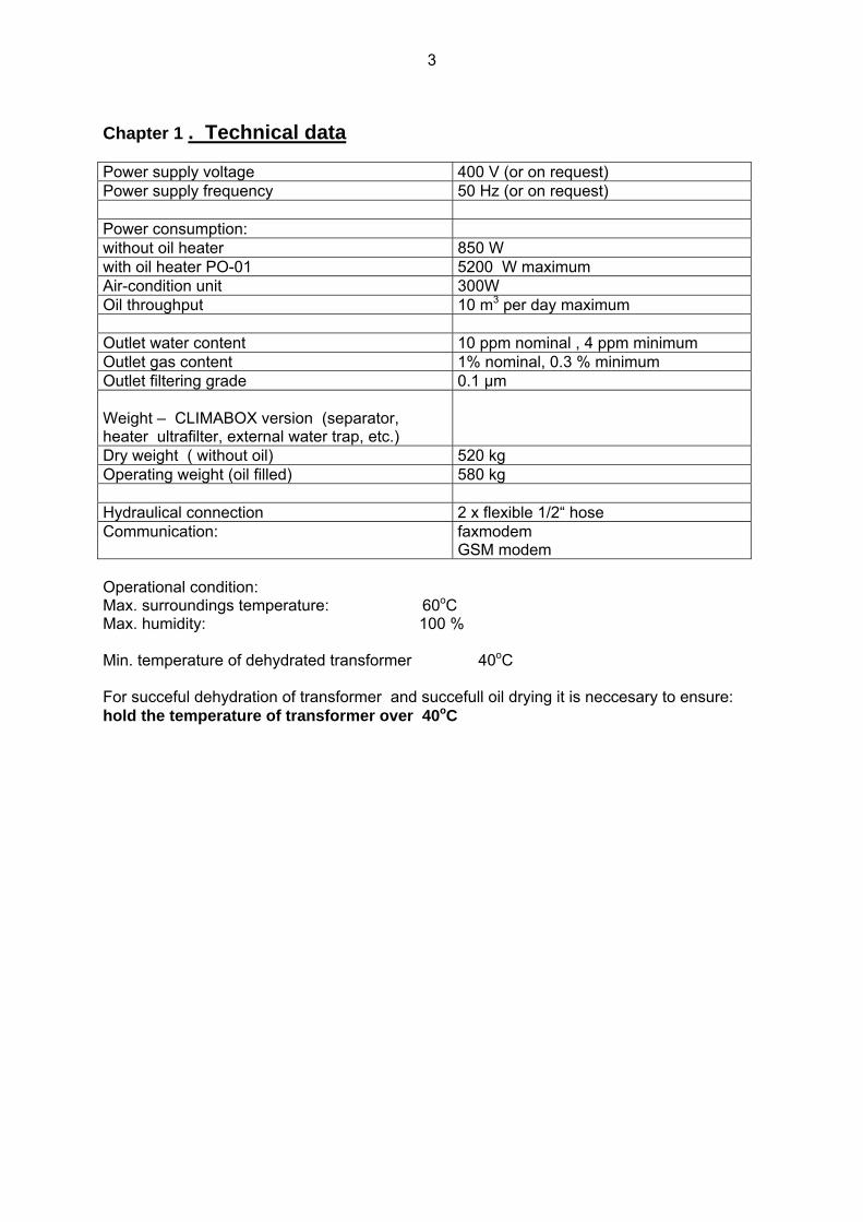
Chapter 1 . Technical data Power supply voltage 400 V (or on request) Power supply frequency 50 Hz (or on request) Power consumption: without oil heater 850 W with oil heater PO-01 5200 W maximum Air-condition unit 300W Oil throughput 10 m3 per day maximum Outlet water content 10 ppm nominal , 4 ppm minimum Outlet gas content 1% nominal, 0.3 % minimum Outlet filtering grade 0.1 µm Weight – CLIMABOX version (separator, heater ultrafilter, external water trap, etc.)
Dry weight ( without oil) 520 kg Operating weight (oil filled) 580 kg Hydraulical connection 2 x flexible 1/2“ hose Communication: faxmodem
GSM modem Operational condition: Max. surroundings temperature: 60oC Max. humidity: 100 % Min. temperature of dehydrated transformer 40oC For succeful dehydration of transformer and succefull oil drying it is neccesary to ensure: hold the temperature of transformer over 40oC

4
Chapter 2 . Installation The separator VS-06 A CLIMABOX is attached to the transformer as shown in Fig.1.
Installation procedure:
• attach the oil-inlet set (coupling, insulation insert and servo valve YV4 See Fig.1) to the lower access of the transformer (i.e. bottom filter press cock), then connect to the open end of the servovalve YV4 the in-let hose H1, then connect the opposite end of the hose H1 to the hydraulic connector HC1 (see Fig.2 – right side of the CLIMABOX -cock K-IN), open the cock K-IN
• attach the oil-outlet set (coupling, insulation insert and servo valve YV3 See Fig.1) to the upper access of the transformer (i.e. upper filter press cock), then connect to the open end of the servovalve YV3 the out-let hose H2, then connect the opposite end of the hose H2 to the hydraulic connector HC2 (K-OUT), open cock K-OUT
• remove the face and rear cover of the CLIMABOX
• check if all cocks on right and left side of separator and at the rear side are full open
• check if all 3 filter insterts of the ultrafilter are installed
• connect cable of servo valve YV4 to the input servo-connector
• connect cable of servo valve YV3 to the output servo- connector
• check the correct level of the supply voltage (required 400 V +/- 15V) Five wire connection cable and connector (3x400V, PE,N) is neccesary (N-light blue 0-phase, PE-green-yellow security)
• set the supply circuit breaker (in the power-supply box ) for a minimum load of 16A, then connect the separator to the power-supply box.
• check DC voltage of the data line (required 42-45V), then connect the data transmission cable to the telephone connector
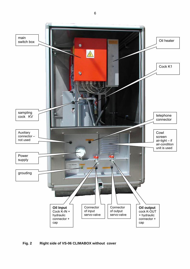
Right side of VS-06 which is used for a hydraulic connection to the transformer, the power supply and the communication, is shown on Fig.2.
Left side of VS-06 is equipped either with air-condition unit (for air temperatures over 40C) or in the left niche is installed the stainless-steel sieve – for air temperatures under 40C.
Flow diagram of VS-06 is shown on Fig. 3.
Detailed internal layout of VS-06 – the face part - inclusive external water trap is shown in Fig. 4.
Rear part of VS-06 is shown in Fig. 5 .
First start-up of the VS-06 has to be carried out by the manufacturer himself or through from him authorized service technicians.
ATTENTION ! Check the oil-level in the conservator tank always before first start up of the VS-06.
• oil level should exceed the minimum mark by 1/3 of the scale in the conservator
• survey this level continuously during the start-up procedure and during the operational condition – the oil level in the conservator tank shall never fall below the minimum level indicator
• if the oil level would fall below the minimum mark of the conservator tank, refill oil immediately or/and use a auxiliary conservator

5
Fig.1 Instalation of VS-06
6
Fig. 2 Right side of VS-06 CLIMABOX without cover
main switch box
sampling cock KV
Oil heater
telephone connector
grouding
Power supply
Auxiliary connector – not used
Oil Input Cock K-IN + hydraulic connector + cap
Connector of input servo-valve
Oil output cock K-OUT + hydraulic connector + cap
Connector of output servo-valve
Cowl screen air-tight – if air-condition unit is used
Cock K1

7
1 Hermetized pump 19 oil leakage sensor................ BQ3 2 main vacuum chamber 20 flusching valve 3 wet gas accumulation chamber 21 external water trap 4 wet gas separator 22 water removal cock 5 oil accumulator 24 air bleed valve 6 collecting chamber 7 inlet ejector 8 process ejector P1 pump mano-vacuum gauge 9 gas flow monitoring chamber BP1 pump pressure sensor 10 batch unit P2 main chamber gauge 11 cooling chamber BP2 main chamber pressure sensor 12 cooling compressor............... M3 P3 collecting chamber gauge 13 fan..............................………. M2 BP3 collecting chamber pressure sensor 14 Defrosting valve...............…..YV1 BT1 freezing chamber temperature sensor 15 fan thermostat .................….ST1 BQ1 batch unit water level sensor 16 Exhaust valve BQ2 ext. water trap water level sensor 17 throtle valve 18 oil trap tube
Fig. 3 The flow diagram of the internal part of the VS-06 CLIMABOX
8
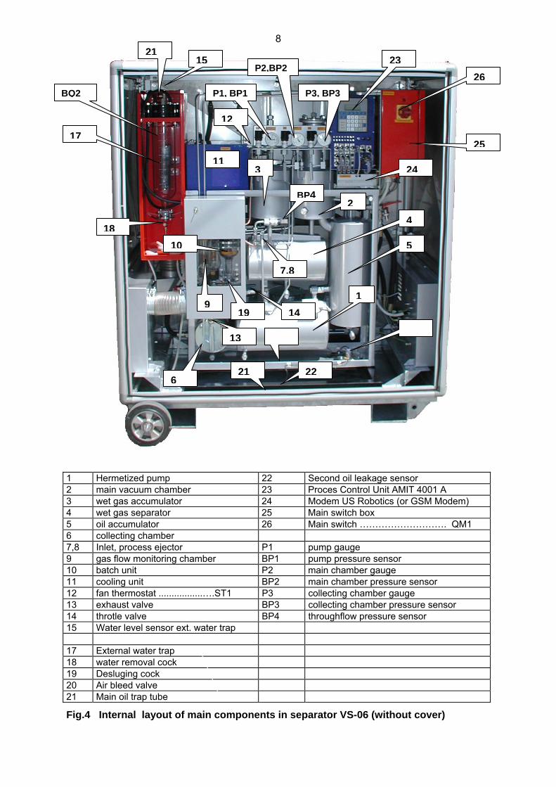
1 Hermetized pump 22 Second oil leakage sensor 2 main vacuum chamber 23 Proces Control Unit AMIT 4001 A 3 wet gas accumulator 24 Modem US Robotics (or GSM Modem) 4 wet gas separator 25 Main switch box 5 oil accumulator 26 Main switch ………………………. QM1 6 collecting chamber 7,8 Inlet, process ejector P1 pump gauge 9 gas flow monitoring chamber BP1 pump pressure sensor 10 batch unit P2 main chamber gauge 11 cooling unit BP2 main chamber pressure sensor 12 fan thermostat .................….ST1 P3 collecting chamber gauge 13 exhaust valve BP3 collecting chamber pressure sensor 14 throtle valve BP4 throughflow pressure sensor 15 Water level sensor ext. water trap 17 External water trap 18 water removal cock 19 Desluging cock 20 Air bleed valve 21 Main oil trap tube
Fig.4 Internal layout of main components in separator VS-06 (without cover)
26
1
22
5
4
24
25
P2,BP2
P3, BP3BQ2 P1, BP1
2321
17
11
BP4
14
1018
19
3
12
6
7,8
13
9
2
15
21
9
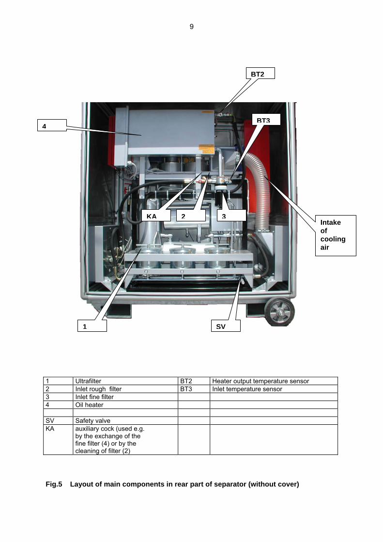
1 Ultrafilter BT2 Heater output temperature sensor 2 Inlet rough filter BT3 Inlet temperature sensor 3 Inlet fine filter 4 Oil heater SV Safety valve KA auxiliary cock (used e.g.
by the exchange of the fine filter (4) or by the cleaning of filter (2)
Fig.5 Layout of main components in rear part of separator (without cover)
1
2
SV
3Intake of cooling air
4
BT2
BT3
KA
10
Chapter 3 . Function
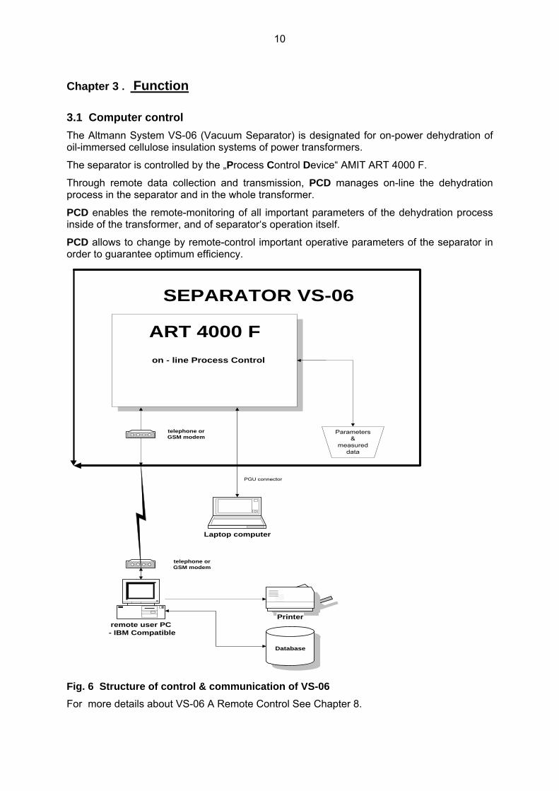
3.1 Computer control The Altmann System VS-06 (Vacuum Separator) is designated for on-power dehydration of oil-immersed cellulose insulation systems of power transformers.
The separator is controlled by the „Process Control Device“ AMIT ART 4000 F.
Through remote data collection and transmission, PCD manages on-line the dehydration process in the separator and in the whole transformer.
PCD enables the remote-monitoring of all important parameters of the dehydration process inside of the transformer, and of separator‘s operation itself.
PCD allows to change by remote-control important operative parameters of the separator in order to guarantee optimum efficiency.
on - line Process Control
Parameters&
measureddata
remote user PC - IBM Compatible
Database
Printer
Laptop computer
ART 4000 F
SEPARATOR VS-06
PGU connector
telephone orGSM modem
telephone orGSM modem
Fig. 6 Structure of control & communication of VS-06 For more details about VS-06 A Remote Control See Chapter 8.

11
The separator is working practically without any local operator intervention or any necessary operator supervision. The PCD is increasing the self-governing autonomy of the separator. The operator‘s intervention is limited to:
⇒ connecting & disconnecting of the separator to the transformer (See 2. Installation)
⇒ startup of the separator by main-switch QM1 (See Startup – Procedure)
⇒ shutdown of the separator (by main-switch QM1 or pushing F2 key on AMIT terminal) (See Shutdown – Procedure)
Any other in-situ usual activities of the operator are:
⇒ changing the input and output filter inserts - pushing F4 key on AMIT Terminal (See Filter Changing - Procedure)
⇒ removing water from the external water collector - pushing F3 key on AMIT terminal (See Water removal – Procedure)
All this activities are computer controlled and supported. Computer recommends operator desired activity on terminal AMIT and checks the results.
Fig. 7 AMIT Terminal & Supply Unit
Protection and any other function of separator are solved in the same way.
12
Periodical monitoring, change of parameters and all other functions can be realized by remote control.
Table 1 shows list basic programs of VS-06.
These programs are initialized by pushing F1…F4 keys on AMIT terminal, or using the keyboard (for parameter changing).
Tree structure is used:
• First step: Select common program by pusching of F1…F4 key
• APT display then shows another menu (second level)
Example:
After pusching the F1 key in the first step, another choice of menues appears: pushing again F1 key for Parameter change (Parameter Table) , or F2 for Manual Defrost , or F3 for Manual Control
• Second step: Pusching of selected key will start the choosen program.
Table 1 Key control
KEY Activity
F1 F1 – Parameter change , F2 – Manual Defrost , F3 – Manual Control
F2 Computer controlled shutdown
F3 Computer controlled Water Removal
F4 Computer controlled filter Check & Replacement.
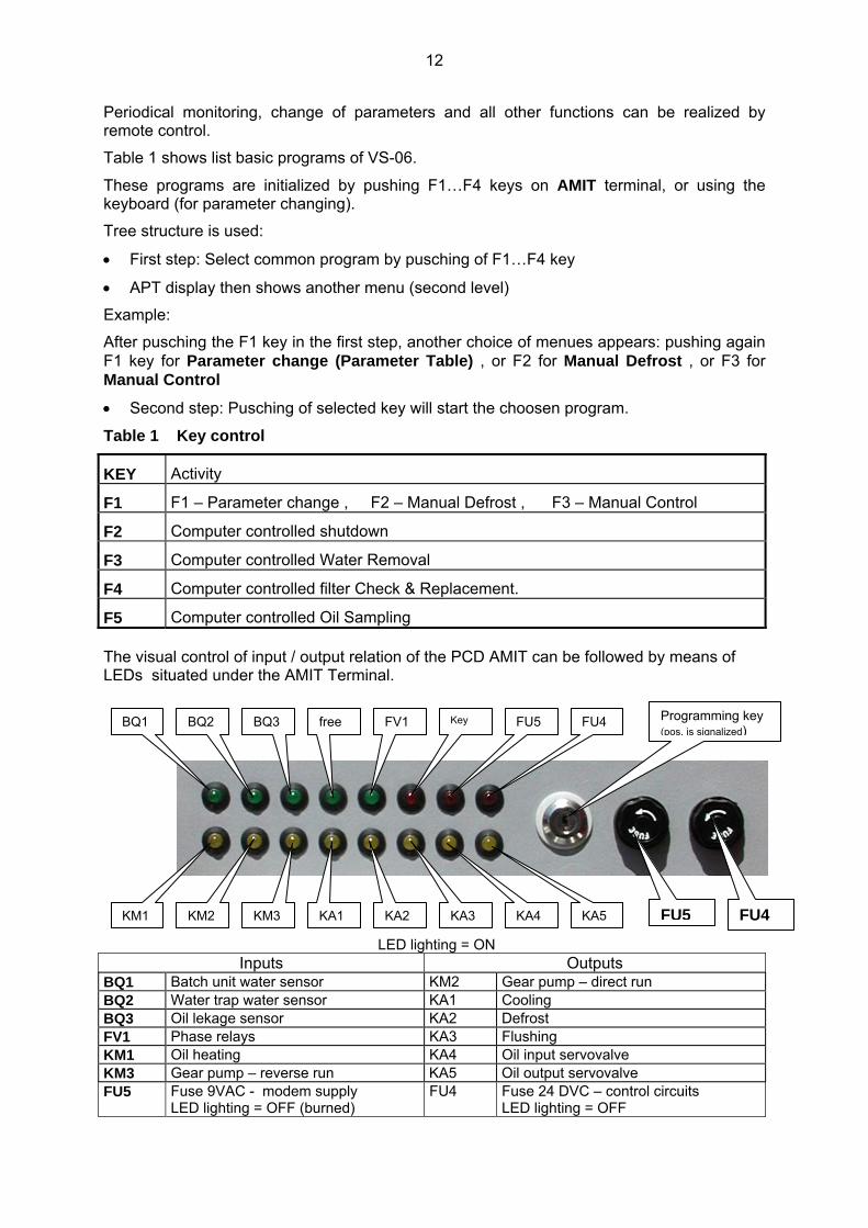
F5 Computer controlled Oil Sampling The visual control of input / output relation of the PCD AMIT can be followed by means of LEDs situated under the AMIT Terminal.
LED lighting = ON Inputs Outputs
BQ1 Batch unit water sensor KM2 Gear pump – direct run BQ2 Water trap water sensor KA1 Cooling BQ3 Oil lekage sensor KA2 Defrost FV1 Phase relays KA3 Flushing KM1 Oil heating KA4 Oil input servovalve KM3 Gear pump – reverse run KA5 Oil output servovalve FU5 Fuse 9VAC - modem supply
LED lighting = OFF (burned) FU4 Fuse 24 DVC – control circuits
LED lighting = OFF
BQ1
KA5KA4
FU4FU5Key FV1free
KA3KA1 KA2KM3 KM2 KM1
BQ3 BQ2 Programming key (pos. is signalized)
FU5 FU4

13
3.2 Startup - Procedure
Note: Components are identified by names and numbers on the diagrams in Fig.1, Fig 2 , Fig.3 and Fig. 4. In the following text, the component numbers are in bold type enveloped by round brackets. Physical locations of these components are indicated in Fig.3 and Fig.4.
Identification of given component is done by figure and position number (or name) – for example inlet ejector in Figure 3 is identified as (F3,7) or Ultrafilter in Fig. 5 is identified as (F5,1)
Preprogrammed parameters are identified by [ ] brackets.
To start the separator switch the main switch QM1 (F4, 26) on the position I (ON).
The APT display (F4,23) shows „date“ and „time“ for checking. You have 5 sec for zero setting of values for T (total time of dehydration), MWC (total amout of separated water until this time in ml) and MW (total water volume in the external water trap in ml).
VACUUM SEPARATOR VS-06 ”date” ”time” ZERO SETTING - ENTER
When the separator is conected to a new transformer for a new dehydration process, the values for T (time of dehydration), MWC (total volume of separated water), MW (actual water volume in the water trap) need to be set to zero.
By pushing ENTER all the registers for T, MWC and MW are set to zero. The display confirms the procedure as follows:
VACUUM SEPARATOR VS-06 MWC = MW = 0 T = 0
When we need to conserve the old values for T, MWC and MW, (continuing the dehydration of the transformer in cure, after shut-down of main switch) - do nothing - only wait ca 5 sec and separator will start to work again with the earlier values..
The automatic start-up procedure first evacuates the whole outflow section of separator, display shows:
SEPARATOR START UP VACUUM PROCESSING IN OUTLET SECTION P1 = P1 P2= P2 (kPa)
If pressure P1 in his section decreases below the preprogrammed absolute pressure [P1MIN], then the servovalve YV3 will open automatically, but the sampling cock is still closed.
Attention : If the pressure P1 will not decrease below [ P1MIN ] level, then the Startup procedure will remain in the first step. The vacuumizing of the outflow section is not succeful and the outflow servovalve remains in closed position.
The AMIT Terminal reports that the desired vaccuum is reached and demands the opening of the upper valve (cock) on the transformer main tank
OUTLET SECTION
14
ON VACUUM P1 = P1 OPEN UPPER VALVE(S) AT MAIN TANK
And the oil from the main tank will flush this section.The flush of oil from the transformer continues automatically until the whole separator is filled with oil. The AMIT Terminal will report:
GAS COMPRESSION P1 = P1 P2 = P2 (kPa)
If pressure P2 exceeds preprogrammed absolute pressure [ P2AUTO ] and gases are expelled from main chamber and gas acumulator, the AMIT Terminal will report Gas Exhaust. This is visible as a stream of gas-bubbles in the glas of the control chamber ( F4,9 ) and then in the plexi glas extension of the exhaust valve (F4,13)
GAS EXHAUST P1 = P1 P2 = P2 (kPa)
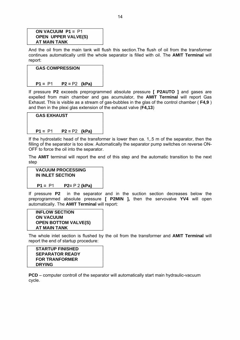
If the hydrostatic head of the transformer is lower then ca. 1,.5 m of the separator, then the filling of the separator is too slow. Automatically the separator pump switches on reverse ON-OFF to force the oil into the separator.
The AMIT terminal will report the end of this step and the automatic transition to the next step
VACUUM PROCESSING IN INLET SECTION P1 = P1 P2= P 2 (kPa)
If pressure P2 in the separator and in the suction section decreases below the preprogrammed absolute pressure [ P2MIN ], then the servovalve YV4 will open automatically. The AMIT Terminal will report:
INFLOW SECTION ON VACUUM OPEN BOTTOM VALVE(S) AT MAIN TANK
The whole inlet section is flushed by the oil from the transformer and AMIT Terminal will report the end of startup procedure:
STARTUP FINISHED SEPARATOR READY FOR TRANFORMER DRYING PCD – computer controll of the separator will automatically start main hydraulic-vacuum cycle.

15
3.3 Separation of moisture and gases The VS-06 separator provides moderate vacuum, moderate heat and large interfacial surface, needed to separate gases and vapours from the oil. All procedures are fully automatized and remote controled, local operator action is not necessary.
3.4 Water removal - Procedure Water removal procedure from water trap (F4,17) can be effected any time by pushing F3 key on AMIT Terminal. The AMIT Terminal will report start of water removal procedure accustically and on display:
WATER REMOVAL ON PRESSURE EQUALIZATION, WAIT P2 = xxx kPa CAUTION The water removal cock (F4, 18) can be opened only if pressure equalizition is indicated. Then a water removal procedure is realized, and cock (F4,18) must be closed again.
OPEN BOTTOM COCK OF WATER TRAP DRAIN OFF WATER PUSH ENTER After pusching ENTER separator goes back to normal separation process
3.5 Oil sampling procedure Oil sampling procedure can be started any time by pushing F5 key on AMIT Terminal. The AMIT Terminal will report this status as: . OIL SAMPLING ON WAIT FOR PRESSURE EQUALIZATION CAUTION Sampling cock ( F2, KV ) , situated under main switch box , can be opened only if pressure equalization (PRESSURE OK ) is indicated. When a sampling procedure is made, cock ( F2, KV ) must be of course closed again. PRESSURE OK SAMPLING FINISHED ? YES - ENTER After pusching ENTER separator goes back to normal separation process
3.6 Shutdown - procedure

16
Separator VS-06 can be any time shut down by : • main switch QM1 • key K2 3.6.1 Main switch
When main switch QM1 is setted OFF in ca 10 sec are closed both servo valves YV3 and YV4. This way is separator quickly a safely disconnect from oil filling of transformer.
When QM1 is setted ON is separator automatically started again
Computer controlled shut- down procedure is inicialized by key F2. Display offers us two procedures
FOR SHORT-TERM SHUTDOWN - PUSH F7 FOR LONG-TERM SHUTDOWN - PUSH F8 3.6.2 Short-term shutdown
After click on F7 display shows SHORT-TERM SHUTDOWN ON WAIT
and standard sequence Water removal 3.4 is started at first.
Using of Water removal procedure as internal procedure of Short-term shutdown is necessary especially under very low surrounding temperatures.
When is this procedure finished goes separator back to normal Short-term shutdown procedure.
: SHORT-TERM SHUTDOWN FINISHED FOR START TURN OFF/ON MAIN SWITCH QM1 3.6.3 Long-term shut down
When water content in the transformer decreases under desired level is dehydration process stopped and separator is transported and connected to another wet transformer .
Separator should be transported without oil and therefore following procedure is used After pusshing of F2 is following display shown again
FOR SHORT-TERM SHUTDOWN - PUSH F7 FOR LONG-TERM SHUTDOWN - PUSH F8
and after pusching F8 is displayed
SHUTDOWN FOR

17
TRANSPORTATION ? YES - ENTER
and sequence of another instructions and mesages are the same as by SHORT-TERM procedure. When WATER REMOVAL is finished and on the display is indicated LONG-TERM SHUTDOWN ON VACUUM PROCESSING ON WAIT
and servo valve YV4 closes immediately and stopts oil inflow in the separator. The pump is turned on, vacuum is builded up and this process continues until separator is emptied.
When proper vacuum is reached, the pump turns off and this state is reported as CLOSE BOTTOM COCK OF TRANSFORMER DISMOUNTE VALVE YV4 PUSH ENTER
DISMOUNTING OF SERVOVALVE HAVE TO BE ALWAYS CARRIED OUT WITHOUT DISENGAGE OF HOSE only by unscrew of female screw – See following Fig.
Only this way remains the hose under vacuum and separator shut-down is not disturbed !! THIS PROCEDURE IS THEREFORE VALID FOR DISMOUNTING BOTH SERVO VALVES
after click on ENTER servo valve YV4 opens and the infowing air is forcing the oil from hose H1 and preheater PO-01 back into separator.
End of this process is reported as OIL EXHAUST FINISHED CLOSE COCK K-IN DISMOUNT HOSE H1 PUSH ENTER
and then follows the next procedure for oil-discharging from outflow section.
18
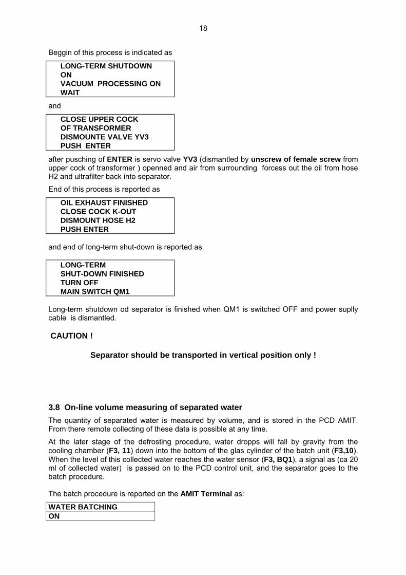
Beggin of this process is indicated as
LONG-TERM SHUTDOWN ON VACUUM PROCESSING ON WAIT
and
CLOSE UPPER COCK OF TRANSFORMER DISMOUNTE VALVE YV3 PUSH ENTER
after pusching of ENTER is servo valve YV3 (dismantled by unscrew of female screw from upper cock of transformer ) openned and air from surrounding forcess out the oil from hose H2 and ultrafilter back into separator.
End of this process is reported as
OIL EXHAUST FINISHED CLOSE COCK K-OUT DISMOUNT HOSE H2 PUSH ENTER and end of long-term shut-down is reported as LONG-TERM SHUT-DOWN FINISHED TURN OFF MAIN SWITCH QM1 Long-term shutdown od separator is finished when QM1 is switched OFF and power suplly cable is dismantled. CAUTION !
Separator should be transported in vertical position only !
3.8 On-line volume measuring of separated water The quantity of separated water is measured by volume, and is stored in the PCD AMIT. From there remote collecting of these data is possible at any time.
At the later stage of the defrosting procedure, water dropps will fall by gravity from the cooling chamber (F3, 11) down into the bottom of the glas cylinder of the batch unit (F3,10). When the level of this collected water reaches the water sensor (F3, BQ1), a signal as (ca 20 ml of collected water) is passed on to the PCD control unit, and the separator goes to the batch procedure.
The batch procedure is reported on the AMIT Terminal as:
WATER BATCHING ON

19
WAIT FOR FLUSHING
The gear pump will run on reverse, and if the pressure P2 exceeds the preprogrammed pressure level [ P2AUTO ] , the flusching valve ( F3,20 ) will be opened, and water (and oil) will be pumped from the batch unit into the water trap ( F3,21 ). See function diagram on Fig. 3.
The batching unit will be flushed twice in order to remove the last water residua, before the whole batching procedure is finalized.
From the time interval between the last and the present batch procedure, and the volume of transported water, PCD calculates the water removal efficiency MWT (ml/24 hod) of separator.
Collected water
water sensor electrode
nut of internal filter
Flusching valve
Desluging cock
Non-return valve
Connector of water sensor
Grounding of water sensor

20
Chapter 4 . Protections The separator VS-06 is designed and build speciffically with remote control in order to operate for prolonged time periods without the necessity of any local supervision.
Therefore it is very important that any significant oil-loss will be ruled-out under any circumstances.
4.1 Oil loss The separator system consists of hermetically sealed hydraulic and condensation circuits and at the rear side is situated the external heater and ultrafilter (See Fig.1 and Fig 4). All these parts are hydraulically connected to the leakage tube in the bottom of the CLIMABOX. Any oil spil in the separator system will be collected in this leakage tube. In the unlikely event of spill, leakage sensor BQ3 (F4,16) mounted in the lowest part the drip tray of the CLIMABOX will then generate oil loss alarm. Immediatedly the separator is stopped, and the servo valves shut-off.
Thus, in 10 seconds of detecting oil-spill, the transformer will be hydraulically isolated from the separator by closing down of the two servo valves YV3 and YV4,.
The oil-leak alarm is indicated acustically and on the display of the AMIT Terminal. OIL LEAK FIND & REPAIR LEAKAGE DRY OUT SENSOR BQ3 RESET BY QM1 OFF/ON After the detecting and sealing of leakage (and drying of container of leakage sensor BQ3 See (F4,16) and the photograph picture showing disassembled sensor), reset the separator by switching main switch QM1 OFF and ON.
drip-tray of the CLIMABOX
Dissasembled sensor with O-ring
Floater in the upper (ALARM) position
Sensor container

21
4.2 Overpressure Hydraulic and vaccum chambers of separator, heater and ultrafilter are protected against overpressure in two levels: • PCD controls the pressure P1 and P2, and will recognize if these values will exceed the
allowed limits [ P1MAX ] / [ P2MAX ] . If this happens, the separator is automatically shut off, and this state is indicated accustically and on the display
If pressure P1 on the pump exceeds [ P1MAX ] , acustic alarm is generated, and display on AMIT Terminal will indicate: OVERPRESSURE P1 ALL VALVES & COCKS ON OUTFLOW ARE OPEN ? RESET BY QM1 OFF/ON If pressure P2 in the main chamber exceeds [ P2MAX ] , acustic alarm is generated, and display on AMIT Terminal will indicate: OVERPRESSURE P2 CHECK SENSORE BP2 BY MEANS GAUGE P2 RESET - QM1 OFF/ON
4.3 Overfill of external water trap, and discharge of external water trap If water level in the water trap (See Fig.3 Position 18) exceeds allowed level, then the water level sensor BQ2 (F2,BQ2) will be activated and separator is shut down. AMIT Terminal will display:
WATER TRAP FULL FOR DISCHARGING PUSH F3 Manual water removal from water trap can be made any time under normal operation of the separator, if one simple condition is fulfilled:

22
The pressure P2 has to be below 100 kPa during the whole removal procedure in order to rule out any unwanted oil-spill.
Manual water removal procedure:
• check the pressure level P2
• remoove cap of air bleed valve
• slowly open the air bleed valve
• slowly open the discharging cock and discharge all water from water trap
• close both cocks
• close air bleed valve with cap
ATENTION ! When the separator is shutted-down and the ambient temperatures are deep below 0oC, the water from the external water trap has to be completely removed.
Air bleed valve
Water sensor electrode
Water sensor grounding
Discharging cock
23
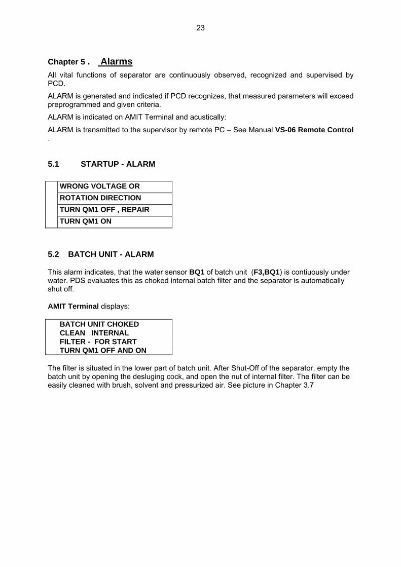
Chapter 5 . Alarms All vital functions of separator are continuously observed, recognized and supervised by PCD.
ALARM is generated and indicated if PCD recognizes, that measured parameters will exceed preprogrammed and given criteria.
ALARM is indicated on AMIT Terminal and acustically:
ALARM is transmitted to the supervisor by remote PC – See Manual VS-06 Remote Control .
5.1 STARTUP - ALARM WRONG VOLTAGE OR ROTATION DIRECTION TURN QM1 OFF , REPAIR TURN QM1 ON
5.2 BATCH UNIT - ALARM This alarm indicates, that the water sensor BQ1 of batch unit (F3,BQ1) is contiuously under water. PDS evaluates this as choked internal batch filter and the separator is automatically shut off. AMIT Terminal displays: BATCH UNIT CHOKED CLEAN INTERNAL FILTER - FOR START TURN QM1 OFF AND ON The filter is situated in the lower part of batch unit. After Shut-Off of the separator, empty the batch unit by opening the desluging cock, and open the nut of internal filter. The filter can be easily cleaned with brush, solvent and pressurized air. See picture in Chapter 3.7

24
Chapter 6 . Maintenance The VS-06 Separator requires minimum maintenance. Neverthelless, it is recommended that a regular maintenance schedule be establisched as described in the following sections .
6.1 Cleaning of internal surfraces of glas chambers By dehydration of wet transformer with heavy aged oil is necessary regular cleaning of all glas chambers and cylinders. The cleaning is provided by serviceman of producer or other authorized person.
6.2 Input filters – Check & Replacement Intensity of inflow of oil in separator is computer controled. If the actual volume of delivered oil decreases under given limit (under setting point of flow indicator BQ4 → BQ4 is OFF ), is this evaluated as a fault and indicated on display of APT as ALARM:
INFLOW TO LOW FOR CHECK & REPLACE INPUT FILTERS PUSH F4
Now is computer asking which filter we want check or replace
FILTER INSERTS REPLACEMENT - FOR INLET FILTERS - F1 FOR OUTLET FILTERS - F2
Because we have trouble with oil inflow the key F1 is used. INLET FILTERS CHECK & REPLACEMENT VACUATION WAIT
Suction side of separator is provided with two filters - first stage drum (metal cloth) rough filter ( See Position 2 on Fig.4) and second stage fine (car) filter (See Position 3 on Fig 4). Both are situated on rear side of separator and have to be checked or replaced together.
To avoid the oil loss is the whole check & removal procedure made under proper vacuum in the separator.
Inlet filter removal procedure always begins with checks of drum (rough) filter.
End of vacuation procedure is indicated as UNSCREW CAP OF ROUGH FILTER AND CHECK HIS CHOKING
After checking and cleaning of rough filter we get following display
ROUGH FILTER OK ? YES – ENTER

25
if is rough filter closed with cap again we can confirm it by ENTER
and replacement procedure of fine filter (See Position 3 on Fig.4 ) is performed
UNSCREW FINE FILTER SCREW ON NEW FILTER
As fine filter normal car filter can be used See Table
Alternative Inlet Filters FIAAM FT 5044 FRAM PH 4854 MANN & H W 950/4 PUROLATOR PER 316 - OC 105
And computer asks if the procedure is finisched INLET FILTERS CHECKED & REPLACED ? YES - ENTER
and after pushing ENTER goes back to STARTUP Procedure
6.3 Replacement of filter inserts of ultrafilter The degree of choking of filter inserts of ultrafilter is computer controlled.
If pressure loss of ultrafilter exceeds given level is this evaluated as Overpressure Alarm and after checking sequence described in Section 4.2 it is indicated as
ULTRAFILTER CHOKED FOR REPLACEMENT PUSH F4
After pusching of F4 PCD asks again what filters we want check or replace
FILTER INSERTS REPLACEMENT - FOR INLET FILTERS - F1 FOR OUTLET FILTERS - F2
We confirm our decision by pusching F2
OUTFLOW FILTERS CHECK & REPLACEMENT ULTRAFILTER VACUATED WAIT
To avoid the oil loss the whole check & removal procedure have to be made under proper vacuum in the ultrafilter and separator.
Proper underpressure is indicated as

26
VACUUM OK , UNTIGHT LIGHTLY ALL CENTRAL SCREWS - WAIT OIL EXHAUST IS ON
Under this conditions (all central screws are sligtly untight), atmospheric air slowly and uniformly forces oil from all chambers of ultrafilter back in vacuum in the separator. The end of this procedure is indicated as
LIFT OFF ALL CAPS REPLACE FILTER INSERTS IF ALL REPLACED PUSH ENTER
After pusching ENTER goes PCD back into STARTUP procedure.
27
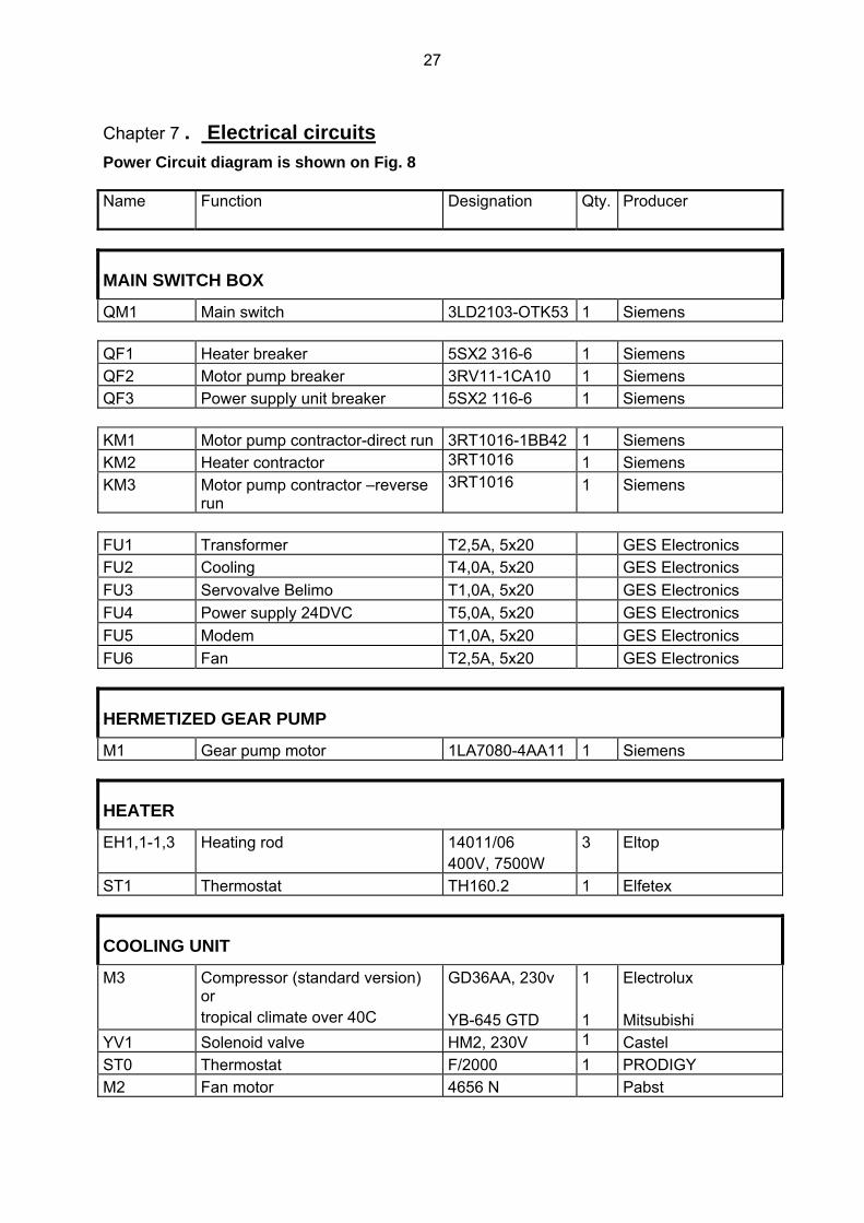
Chapter 7 . Electrical circuits Power Circuit diagram is shown on Fig. 8 Name Function Designation Qty. Producer
MAIN SWITCH BOX
QM1 Main switch 3LD2103-OTK53 1 Siemens QF1 Heater breaker 5SX2 316-6 1 Siemens QF2 Motor pump breaker 3RV11-1CA10 1 Siemens QF3 Power supply unit breaker 5SX2 116-6 1 Siemens KM1 Motor pump contractor-direct run 3RT1016-1BB42 1 Siemens KM2 Heater contractor 3RT1016 1 Siemens KM3 Motor pump contractor –reverse
run 3RT1016 1 Siemens
FU1 Transformer T2,5A, 5x20 GES Electronics FU2 Cooling T4,0A, 5x20 GES Electronics FU3 Servovalve Belimo T1,0A, 5x20 GES Electronics FU4 Power supply 24DVC T5,0A, 5x20 GES Electronics FU5 Modem T1,0A, 5x20 GES Electronics FU6 Fan T2,5A, 5x20 GES Electronics
HERMETIZED GEAR PUMP
M1 Gear pump motor 1LA7080-4AA11 1 Siemens
HEATER
EH1,1-1,3 Heating rod 14011/06 400V, 7500W
3 Eltop
ST1 Thermostat TH160.2 1 Elfetex
COOLING UNIT
M3 Compressor (standard version) or tropical climate over 40C
GD36AA, 230v YB-645 GTD
1 1
Electrolux Mitsubishi
YV1 Solenoid valve HM2, 230V 1 Castel ST0 Thermostat F/2000 1 PRODIGY M2 Fan motor 4656 N Pabst

28
AC/DC Supply
TM1 Transformer 51265-P1S2 1 NT MAGNETICS VD1 rectifier 1 Altmann TM0 Autotransformer ( special order -
only for insulated grids) TAC 35052-0010 1 Elektrokov Znojmo
AIR CONDITIONER
M4 Fan 7450 ES 1 Pabst ST 01 Thermostat F/2000 1 PRODIGY
CONTROL & SUPPLY UNIT
PCD Proces Control Unit ART 4000F 1 AMIT KA1,3,4 Power switch – compressor,
water batch, oil input Belimo 3TX7004-1MBO 3 Siemens
KA2 Power switch - defrost 3TX7004-3AC03 1 Siemens KA5 Power switch – oil ouput Belimo 3TX7002-1FB02 1 Siemens
COMMUNICATION UNIT
Modem 1 US Robotics or GSM Modem TC35i Terminal 1 Siemens Process sensors 4-20 mA BP1 Pressure sensor DMP331
0 – 6 b 1 BD Sensors
BP2,3,4 Pressure sensor DMP331 0 – 2.5b
1 BD Sensors
BT1 Temperature sensor Flexitemp 60 -50 +60oC
1 JSP Jicin
BT2,3 Temperature sensor TG5 0 – 100oC
APO Elmos
ON/OFF sensors BQ1 Batch unit (water level) WLS1 1 Altmann BQ2 Water trap (water level) WLS1 1 Altmann BQ3 Leakage sensor RSF54Z100RC 1 Cynergy 3 FV1 Rotation direction/Voltage check
& Reading relay 3Ug4615-1CR20 1 Siemens
Lighting switch S1 Limit switch HL408 1 GES Electronics

29
Fig. 8 Power circuit diagram

30
Chapter 8 - Remote Control 8.1 Program installation Program ALTMANN V2.0 - delivered CD disk - contains the main program for the remote (and in situ) control and the monitoring of VS-06 and additional sub-programs that enable an easy installation of the whole firmware into your computer.
Installation procedure:
• insert ALTMANN CD into disk drive (usually D)
under a normal operational condition is CD installed automatically
if not
• choose START and press RUN
• type D:\setup.exe. into the command line
• Press OK (Enter) to confirm the procedure.
• After the SETUP panel has appeared, click on TARGET and choose the target directory into which you want to install the program. The program will offer you one of the possibilities ( C:\ Altmann ). Press OK to accept this offer
• Click on START and program SETUP will install program ALTMANN into your computer
• Press OK (Enter) to confirm the procedure
and your PC will offer you a window with the firm icon.
8.2 Starting the program
Click on the Altmann´s firm icon to launch the program. Having launched the program basic windows will appear.

31
The toolbar contains the following buttons and tools - click on particular buttons of the toolbar to enter various applications
8.3. Remote communication
Click on the icon opens the new window for the choice of the telephone number of the desired separator.
Attention : Before beginning a communication the programming of Communication Setup and Telephone directory is neccessary After click on the Connect the modem is started and the connection realized. The operational data separator are transfered at three time levels and summoned under auxiliary toolbar:

32
8.4 Data Transfer Button
o last seven days ( button Days)
o last 24 hours (button Hours)
o last 240 min. (button VirtualOn-Line)
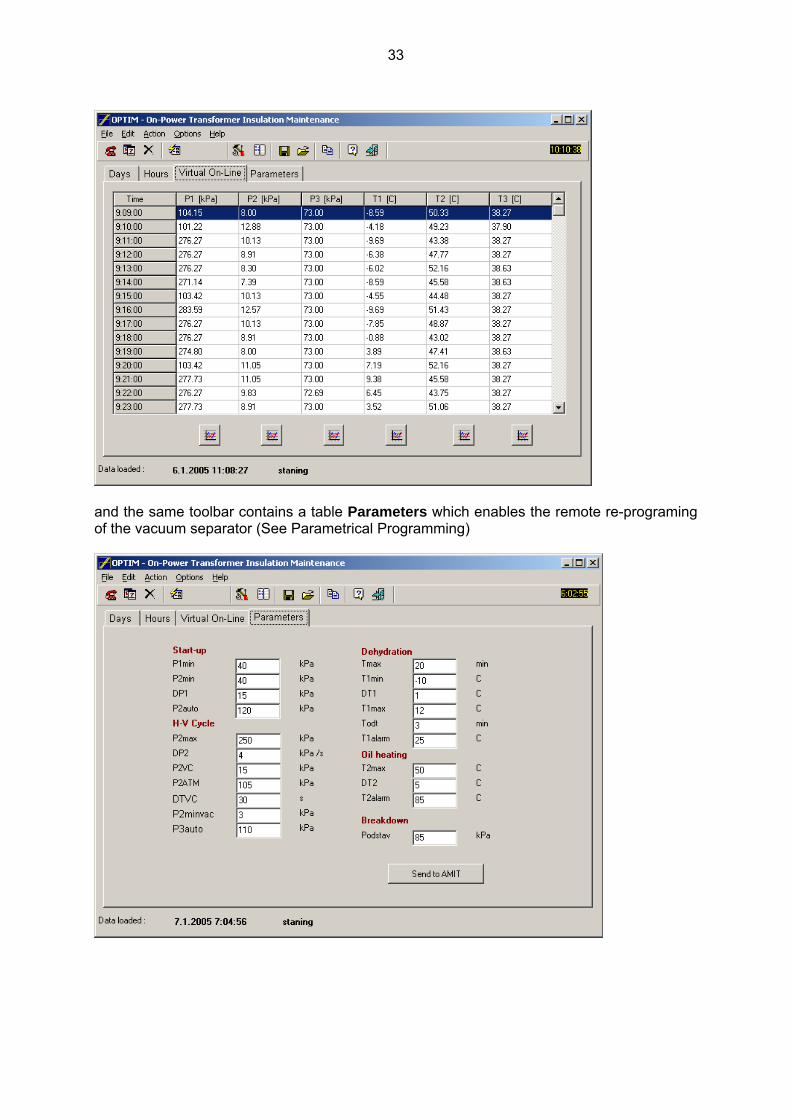
33
and the same toolbar contains a table Parameters which enables the remote re-programing of the vacuum separator (See Parametrical Programming)
34
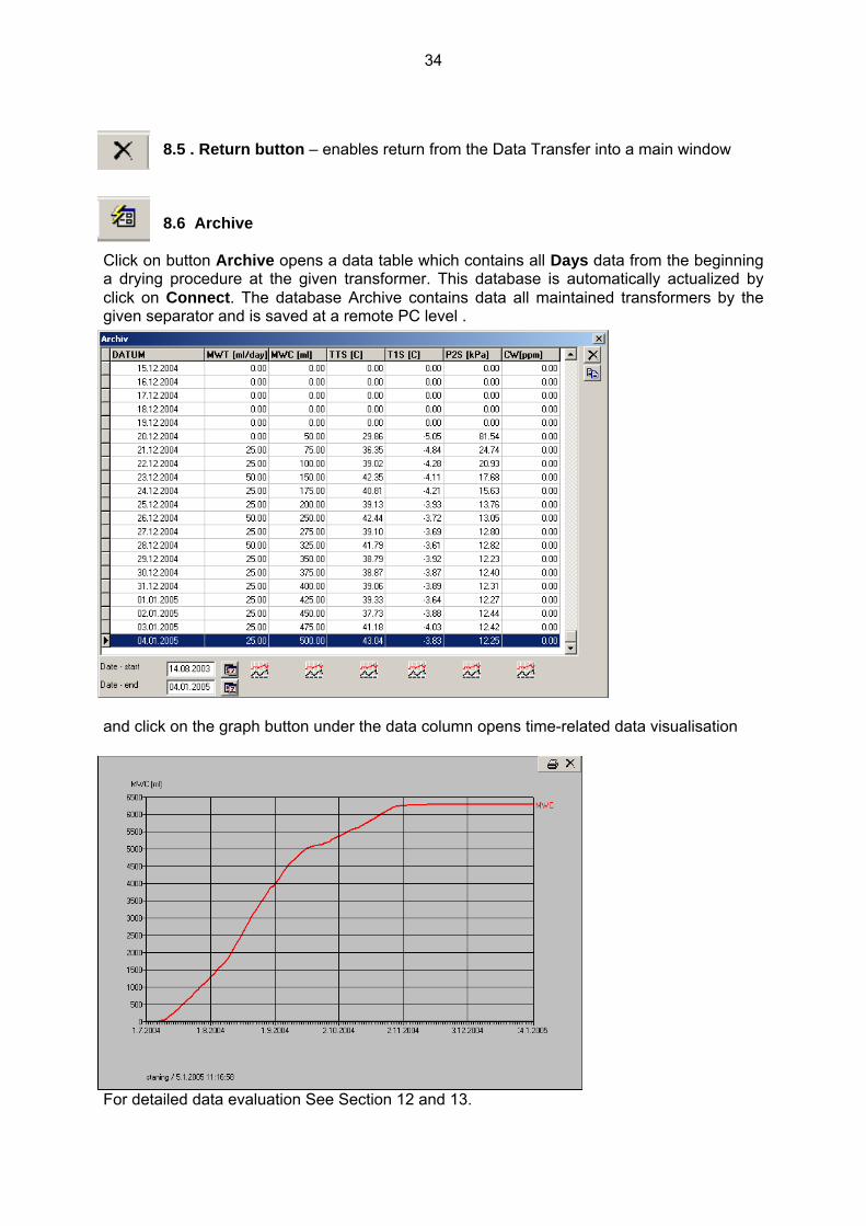
8.5 . Return button – enables return from the Data Transfer into a main window
8.6 Archive
Click on button Archive opens a data table which contains all Days data from the beginning a drying procedure at the given transformer. This database is automatically actualized by click on Connect. The database Archive contains data all maintained transformers by the given separator and is saved at a remote PC level .
and click on the graph button under the data column opens time-related data visualisation
For detailed data evaluation See Section 12 and 13.

35
8.5 . Return button – enables return from the Data Transfer into a main window
8.6 Archive
Click on button Archive opens a data table which contains all Days data from the beginning a drying procedure at the given transformer. This database is automatically actualized by click on Connect. The database Archive contains data all maintained transformers by the given separator and is saved at a remote PC level .
and click on the graph button under the data column opens time-related data visualisation
For detailed data evaluation See Section 12 and 13.

36
8.8 Telephone directory
The „telephone directory“ database is used to avoid mistakes and for fast choice of the communication with the separator. For actualizing choose button on the toolbar
Click on NEW to define the connection with a newly installed separator - a new „card“ of the telephone directory will appear.
It is possible to write down in the new record very carefully all desired data concerning given transformer to avoid a very unpleasant mutual exchange of maintained transformers.
• (identification) name - customer name, location, Serial Number (S/N) of a given transformer
• connection
having chosen the modem connection write down into the Phone window:
♦ the number of the telephone line assigned to the separator
♦ or the number of the separator GSM modem
♦ the COM connection is destined for a direct cable connection of PC or lap-top with an internal computer ( for detailed in-situ data transfer procedure See ….)
• Put down the name of the directory where you will archive the monitored data
• Click on Save to put down required connection in memory

37
Button Edit serves to actualize records in the telephone directory. Click on Edit to open the following window
where you can change any items and confirm it by the button Save or you can the change cancel by click on button Cancel. If you need to cancel any record from the Telephone directory you can do it very easy by click on Delete and the following window will be opened and confirm clicking on Ano (Yes) or you can go back to Telephone Directory by click on Ne (No).
8.9 Save
click on Save will store data Days, Hours, Virtual-On line a Parameters of a given separator into a time- specified file.
8.10 Open
This command opens time-specified files and shows them under Optim A enviroment (See Data Transfer).
8.11 Copy to Clipboard
Command Copy to Clipboard saves the data from the actual screen into a clipboard file and this packet can be freely used e.g. by Excel. 8.12 Standard communication with the separator
Do you want remove the given record from Telephone Directory

38
After setup you can start proper communication between your PC and the separator pushing button this action will open a panel
after you have finished the choice of a particular number, click on Connect – it will start the communication (RUNDMODEM procedure) and will show the following panel
if the connection fails, the program opens the following window This may happen when the phone or GSM network is busy – simply repeat the process to get the connection. After achieved the satisfactory connection the program loads the data from PCD in your PC and shows them in the main window.

39
In order to cut communication fees, the program always works off-line – takes the pre-worked data from PCD, checks them and switches off.the connection.
The program offers implicitly so called Days data first – this means the PCD measured 6 quantities are averaged over 24 hours and stored in PCD for 7 days.
Together with the day values the program also loads so called Hours data – PCD measured 5 quantities are averaged over 1 hour and stored in PCD for 24 hours.
Day and hour averages can be also showed in the form of diagrams pushing the graph button below each column of the values.
The same is used for the Virtual On-Line procedure which dominantly serves as a check of the proper function of vacuum separator self.
The PCD of the separator can ( only on demand of PC !) implicitly scan , average and store the following basic values send at any time to the remote user PC:
MWT …. water removal rate (ml/24 day) MWC….. total amount of water removed from a particular transformer (ml) TTS …. temperature of the transformer derived from oil temperature inflowing
into the separator [oC] T1S ….. temperature of freezing trap [oC] P2S averaged vacuum of separation process [kPa] CWS water content in inflowing oil [ppm] ( if humidity sensor is installed ) 8.13 Parametric process control To optimize of the separator function and the dehydration process of the transformer, click on button Parameters . This action will open the following panel
Every basic function of the separator (from start up to shut down) can be parametrically programmed, but:
ATTENTION !!
40
Except for the temperature T2MAX (the required output temperature of the preheater), no change of parameters is advisable. Parameters are already optimally pre-set. If you want to change any parameter consult it with your dealer or producer of the separator first. Adjusting parameters
• Re-write the given parameter to change it
• Click on button Send to AMIT to send the changed value back to the separator PCD
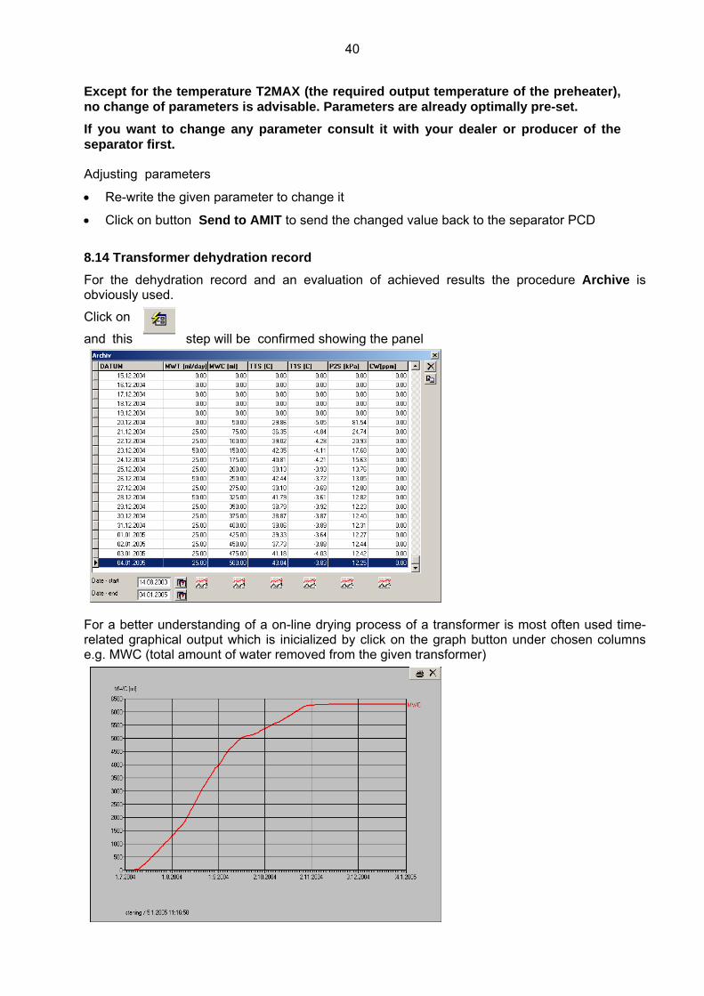
8.14 Transformer dehydration record For the dehydration record and an evaluation of achieved results the procedure Archive is obviously used.
Click on
and this step will be confirmed showing the panel
For a better understanding of a on-line drying process of a transformer is most often used time-related graphical output which is inicialized by click on the graph button under chosen columns e.g. MWC (total amount of water removed from the given transformer)

41
and TTS (transformer temperature )
The comparison of both time-related graphs gives us very often plausible answer at a basic questions about the drying process.
In this case is quite obvious that the reduction of the amount of removed water was induced by the strong decline of the transformer temperature. 8.15 Optimization of the on-power dehydration of transformers .
The relevant moisture and dielectric diagnostics is always absolutely necessary before the beginning of any dehydration procedure.
The SIMMS and TRACONAL should be used to evaluate
the water content in the cellulose materials of the transformer.
To avoid a overdrying of transformer the dehydration target has to be defined .
Do not forget, regardless of how efficient any method of oil dehydration might be, the water removal from the transformer under normal operational conditions - the transformer dehydration - is ultimately governed by slow diffusion of moisture from cellulose and this process can be accelerated only by high temperature.
That is why you always have to describe any dehydration process of transformer with at least two values – MWT (average water removal rate and ) or MWC (total amount of removed water) and TTS ( temperature of the transformer).
In order to avoid lowering the immediate reliability of the transformer we have to tune at least two antagonistic criteria:
• max. separating efficiency of the separator (max. water removal rate)
• dielectric strength of oil - has to be maintained or improved
The first criterion is fully understandable – we want to dehydrate the transformer as soon as possible. Thus we need to release maximum of water
42
from the cellulose into the oil filling by raising the temperature of the transformer.
This fundamentally collides with the second criterion – if the temperature of the wet transformer will be too high, water contents in oil may easy exceed 30 ppm limit and the dielectric strenght of oil drops relatively quickly under 40 –
50 kV/2.5mm. If the moisture sensor is installed, follow always its on-line reading. The Cw-
value should never exceed 30 ppm.
To solve the dilemma between both criterions the method of gradual heating of the transformer is recommended especially if an on-line Cw-reading isn´t available:
• check at first both actual values of water content in the oil (Cw-value) and dielectric strength of the oil (Ud-value).
If the Cw-value is substantially under 30 ppm, increase the temperature TTS of the transformer, about 10 C, wait 5 days and check the result, if necessary, repeat the procedure until the Cw-value is about 20 – 25 ppm is reached
If the Cw-value is about 30 ppm, decrease the temp. ca 5 C, check the result
If the Cw-value is substantially over 30 ppm, the temp. has to be immediately decreased until the allowed Cw-level is reached and simultaneously the Ud-level will be over 30 kV/2.5mm.
To make the whole procedure easier, the on-line reading of the Cw-value is recommended – the installation of a proper moisture sensor in the separator is very simple.
• check daily water removal rate MWT and the transformer temperature TTS on your PC
• when MWT is between 50 – 120 ml/day (and TTS is virtually constant) and the dehydration process is OK operate the transformer at this temperature until the output decreases below 50 ml per day (or any lower output the operator chooses )
• when MWT drops to less then 50 ml/day, increase the transformer temperature TTS about 5 – 7oC .
• when MWT exeeds 120 ml/day decrease the temperature TTS about 2-5oC
• Repeat the preceding steps as many times as necessary to reach the maximum operating temperature of the transformer. (usually 65- 85oC)