validation of advanced driver assistance systems by ...elib.dlr.de/96876/1/paper.final.pdf ·...
TRANSCRIPT

Mobil.TUM 2015 – International Scientific Conference on Mobility and Transport June 30th and July 1st 2015, Munich Technologies, Solutions and Perspectives for Intelligent Transport Systems.
1
Validation of advanced driver assistance systems by airborne optical imagery Franz Kurz Remote Sensing Technologies, German Aerospace Center, Münchener Str. 24, 82234 Wessling, Germany Dominik Rosenbaum, Hartmut Runge, Peter Reinartz Remote Sensing Technologies, German Aerospace Center, Münchener Str. 24, 82234 Wessling, Germany
Abstract
Combinations of advanced driver assistance systems (ADAS) enabling semi-autonomous driving are now being brought to market. Recently developed ADAS are amongst others the adaptive break control, the lane keeping assist and the lane change support. The complexity in the development of these systems increases, as fully autonomous vehicles should become a reality within the next decade. The use of airborne optical sensors can be an independent tool to validate ADAS operating at test sites or in real traffic. The German Aerospace Center (DLR) has developed an optical camera system which is installed on a helicopter for a variety of traffic monitoring applications. With this system, it is possible to track a single test vehicle and to monitor the vehicle with the surrounding traffic situation. The camera system can acquire high resolution images with 54Mpix and a frame rate below 12fps or 4k (Ultra-HD) videos with 25fps. In combination with a high-end GNSS/IMU system, the images and videos can be timely registered within milliseconds precision and georeferenced with an absolute accuracy better than one meter, i.e. the instantaneous position, timestamp and speed of the test and surrounding vehicles can be derived very accurate. Additionally, the positions and speed of front and rear traffic can be determined automatically, which are necessary for the validation of ADAS. In combination with automatic image analysis tools, the road markings can be extracted, which allows the relative positioning of vehicles with respect to the road markings and the surrounding traffic within few centimetres. In this contribution, the potential of airborne optical imagery for the validation of ADAS is presented and demonstrated on example imagery and videos taken from motorways in Germany.
Introduction
Autonomous vehicles have to range in the traffic flow, must keep their lane and must be capable to automatically overtake other vehicles. Advanced driver assistance systems (ADAS) support the driver or take over the control like in autonomous cars. Safety and the perfect interaction of all components are crucial, because the system has to react quickly to the other road user. To accomplish this surround view systems are necessary, which acquire the position, speed and direction of the surrounding vehicles in real-time. The position, speed and direction of surrounding vehicles can be very well measured with radar devices and active infrared based sensors. It is more difficult to detect very early when a vehicle starts moving out the lane in order to react quickly and appropriately. The development of such techniques and procedures requires an optimization of the overall system which can be eased with precise reference data from an independent system which looks at the scene from the outside. For this we have developed a concept for the development and validation of ADAS with an airborne system which acquires high resolution video imagery. The reference vehicle and its surroundings are always kept in the field of view and each video frame is tagged with a precise time stamp.

Mobil.TUM 2015 – International Scientific Conference on Mobility and Transport June 30th and July 1st 2015, Munich Technologies, Solutions and Perspectives for Intelligent Transport Systems.
2
The data can be used for comparison with the stored sensor data from the reference vehicle. With the view from the top the surround sensors can be validated precisely. Furthermore, the overall performance of the integrated driver assistance systems, like the realized trajectories, can be evaluated. In this paper, the potential of airborne optical imagery for the validation of ADAS based on defined scenarios and an automatic processing workflow is presented. First, the validation strategy and the scenarios are described. Relevant parameters are defined in the scenarios, which can be validated by airborne optical imagery. Then, an automatic workflow to derive the parameters from the airborne optical imagery is presented. Finally, the geometrical accuracies of airborne imagery and of the vehicle based sensor are compared and some experimental results are presented.
Validation scenarios
In this chapter, the scenarios are described, in which airborne optical imagery can help to validate advanced driver assistance systems. In the first instance, we aim not to validate the assistance systems as a whole, but we focus on validating the vehicle based measurements of the vehicle`s sensors with respect to their geometrical accuracy. Thus, our scenarios are not structured by the different ADAS; instead we try to define scenarios, where we can compare the vehicle sensor measurements of a reference vehicle directly with parameters derived from the airborne optical imagery. All scenarios with name A to E are illustrated in figure 1. All parameters defined in the scenarios can be derived directly from the optical imagery and partly from the vehicle based sensors. Below the scenarios are listed with their parameters. These parameters are called reference parameters in the following chapters.
Scenario A: observation of the surrounding traffic, relative distance and speed, position and heading of surrounding vehicles
Scenario B: detection of lane markings (standard case), Euclidean distance to the reference vehicle on both sides
Scenario C: detection of lane markings (complex situation), Euclidean distance to the reference vehicle on both sides
Scenario D: observation of reference vehicle parameters, absolute position, absolute speed and heading of the reference vehicle, Euclidean distance to the road database segment, and current traffic lane of the reference vehicle.
Scenario E: observation of road edges without lane markings1, Euclidean distance to the road edges
1 Scenario for future ADAS

Mobil.TUM 2015 – International Scientific Conference on Mobility and Transport June 30th and July 1st 2015, Munich Technologies, Solutions and Perspectives for Intelligent Transport Systems.
3
Figure 1: Illustration of scenarios A to E for the validation of driver assistance systems
Airborne sensor technology
The 4k system is a proprietary real-time optical sensor system of the German Aerospace Center (DLR) originally developed for a wide variety of applications, e.g. for automatic traffic data extraction and for rapid mapping applications. The sensor system is designed weight-optimized, small, and relatively low-cost, but equipped with a full real-time image processing chain including a high-capacity data downlink to the ground station. Figure 2 shows the sensor system mounted on a DLR helicopter and the components of the 4k system with three non-metric off-the-shelf cameras, a microwave datalink system including two antennas, three processing units and a high-end GNSS/IMU system. The 4k system is certified for the BO105 helicopter and mounted on an external cargo carrier on the right side 10cm above the helicopter skids. The platform and housing of the 4k system is decoupled from the helicopter vibrations by using four absorbers inside the system housing. These absorbers mainly decouple from the vibrations caused by the main rotor and the four rotor blades (7Hz, 28Hz).

Mobil.TUM 2015 – International Scientific Conference on Mobility and Transport June 30th and July 1st 2015, Munich Technologies, Solutions and Perspectives for Intelligent Transport Systems.
4
Figure 2: 4k system mounted on the helicopter BO-105 (left) and system components (right)
The system is connected to the 28V/35A power supply of the helicopter and to the GNSS antenna on top of the cabin. The system can be commanded from inside the helicopter via LAN or from the ground station via data link. Three optical non-metric cameras are integrated in the sensor with different looking directions (see Figure 2 right). The latest camera generation from Canon EOS, two 1D-X and one 1D-C, are installed on the platform, which each is capable of acquiring 17.9 MPix images with a frame rate of up to 14Hz. Additionally, the Canon EOS 1D-C is capable of acquiring 4k movies (Ultra-HD) with a resolution of 4096 x 2160 pixels at 25 fps and is installed in nadir direction. Example 4k video frames are shown in figure 3.
Figure 3: single frames (cropped) of a 4k video sequence from helicopter over a construction site (please note that the vehicles in the center left hands are parking) Alternatively, four different lenses from Zeiss with 25mm, 35mm, 50mm and 100mm focal length can be deployed, which leads to different ground sampling distances (GSD) and different footprint sizes on the ground. In figure 4, the footprints of the most common camera and viewing configurations are visualized and the viewing directions relative to the helicopter`s fuselage and skids are outlined. Additionally to the nadir 4k video, the side-looking cameras enhance the field of view significantly. But due to the lower frame rate of the side-looking cameras of 12 fps, we propose here to focus on the 4k video imagery with higher time resolution even if the spatial coverage is smaller. Assuming a flight height of 500 m above ground, the coverage of the nadir 4k video camera is 143 m in flight direction and 253 m in across direction using 50mm lenses. The ground pixel size at this height is then 6.9 cm. By using 35mm lenses the values increases linearly leading to a wider coverage and less ground resolution.

Mobil.TUM 2015 – International Scientific Conference on Mobility and Transport June 30th and July 1st 2015, Munich Technologies, Solutions and Perspectives for Intelligent Transport Systems.
5
With a view to the validation of driver assistance systems, the coverage in flight direction determines the area of the observed road length, i.e. at a flight altitude of 500m the traffic 72 m before and behind the reference vehicle can be observed. A further limitation is the helicopter`s maximum speed of 100 kn when equipped with the 4k sensor, i.e. the reference vehicle should not go faster than 185 km/h. Furthermore, flights during night times make no sense due to the low sensitivity of the cameras.
Figure 4: Viewing configuration and footprints of the 4k system with different configurations
Automatic estimation of reference parameters from airborne video
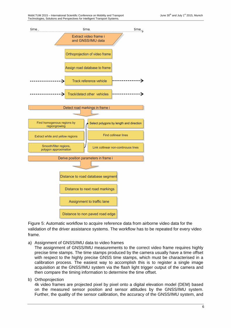
In this chapter, the workflow for the automatic estimation of the reference parameters defined in the scenarios A to E is described in more detail. Due to the immense data amount of 4k video imagery, the manual measurement of the reference parameters would be too time consuming. Furthermore, the geometrical accuracy of automatic methods can outperform the one from the manual measurements. Thus, we propose an automatic workflow based on image analysis methods to derive the reference parameters from the 4k airborne video. The whole workflow is outlined in figure 5, showing all processing steps in order from top to bottom for a single video frame. It should be noted that in the automatic processes which are proposed in the workflow, in particular in the image analysis methods, errors may occur in the completeness and correctness. Thus, the focus of the whole evaluation lies not on the validation of the completeness and correctness but at this stage only on the geometrical accuracy. In the following, the most important processing steps in the workflow are described in more detail.
Mobil.TUM 2015 – International Scientific Conference on Mobility and Transport June 30th and July 1st 2015, Munich Technologies, Solutions and Perspectives for Intelligent Transport Systems.
6
Figure 5: Automatic workflow to acquire reference data from airborne video data for the validation of the driver assistance systems. The workflow has to be repeated for every video frame.
a) Assignment of GNSS/IMU data to video frames The assignment of GNSS/IMU measurements to the correct video frame requires highly precise time stamps. The time stamps produced by the camera usually have a time offset with respect to the highly precise GNSS time stamps, which must be characterised in a calibration process. The easiest way to accomplish this is to register a single image acquisition at the GNSS/IMU system via the flash light trigger output of the camera and then compare the timing information to determine the time offset.
b) Orthoprojection 4k video frames are projected pixel by pixel onto a digital elevation model (DEM) based on the measured sensor position and sensor attitudes by the GNSS/IMU system. Further, the quality of the sensor calibration, the accuracy of the GNSS/IMU system, and

Mobil.TUM 2015 – International Scientific Conference on Mobility and Transport June 30th and July 1st 2015, Munich Technologies, Solutions and Perspectives for Intelligent Transport Systems.
7
the quality of the DEM define the accuracy of the georeference and finally the accuracy of the positions and distances derived from the airborne video. With the corrections of the GNSS/IMU measurements by a bundle adjustment including single video frames, the final georeferencing accuracy is very high and mainly influenced by the underlying DEM accuracy. Also the rolling shutter effect has influence on the final accuracy [2][3].
c) Assign road database to frame Road information stored in a database like NAVTEQ/OSM is valuable prior information for ADAS as well as for the airborne validation workflow. The road information is on the one hand required to support the automatic detection of road marking and surrounding vehicles, on the other hand the position of the reference vehicle relative to the road database segments can be calculated.
d) Automatic detection of surrounding vehicles The automatic detection of vehicles is the most crucial part and consists of a three stage detector, 1) pre-classification with a boosted classifier, 2) blob detection for reducing the number of vehicles hypothesis and 3) final classification of the remaining hypothesis. The processor was developed for low frame rate image sequences but can be adapted to videos. More details can be found in [4]. Additionally, the detector can be trained to distinguish between passenger cars and trucks.
e) Automatic tracking of reference/surrounding vehicle The automatic tracking of the reference and surrounding vehicles is based on a simple NCC (normalized cross correlation) matching which includes also the colour information of the vehicles [4]. For this, sample images of vehicles which are generated by the automatic detection of the surrounding vehicles (step d), or are generated manually for the reference vehicle, are matched in the subsequent video frames by a simple NCC matching algorithm. The search areas for the NCC matching algorithm are quite small due to the high frame rate of 25fps. Figure 6 shows exemplarily the results of an automatic tracking of the reference vehicle in a video sequence. Based on the found positions of the reference/surround vehicles in at least two consecutive video frames, the heading, the speed and all relative parameters can be derived by simple geometrical considerations.
Figure 6: Example for the tracking of a vehicle in a video sequence by simple NCC matching.
f) Automatic detection of road markings The automatic detection of road markings from airborne imagery is without prior knowledge a very challenging task. We propose here a simple and fast approach as the position of the reference vehicle is known and thus the road markings can be detected using some basic assumptions and using the road database information. We assume that there are white or yellow road markings which are brighter than the road surface and there are grey paved roads with homogenous surfaces. Starting with the known position

Mobil.TUM 2015 – International Scientific Conference on Mobility and Transport June 30th and July 1st 2015, Munich Technologies, Solutions and Perspectives for Intelligent Transport Systems.
8
of the reference car, the mean colour of the road surface can be extracted, which makes it easier to separate the white or greyish road markings from the grey road surface. For this step, the image has to be converted into the HSV (hue, saturation, value) colour space. The yellow regions can be extracted by the hue value range, whereas the extraction of the white regions is more difficult due to the different brightness and illumination situations. Grey regions in general have low saturation values and a wide range of values V in the HSV colour space. To separate white markings from the road a threshold must be applied. In figure 8 (left), an automatic method to determine the threshold is illustrated. The full workflow for the automatic detection of road markings is illustrated in figure 7. Starting from the white and yellow regions, outliers must be filtered out, the regions must be smoothed and polygons are approximated. Finally, those segments are selected which are parallel to the direction of the road database.
I) II) III) IV) V)
Figure 7: Workflow of automatic road marker detection from aerial videos; I) original video frame of complex scene with white and yellow road markings; II) find homogenous regions by a regiongrowing algorithm; III) extract white (marked as black in the figure) and yellow regions; IV) filtering, smoothing and polygon approximation of regions; V) selection of lines by segment length and the direction (from road database).
The last step is to determine the distance of the reference vehicle to the road markings. Figure 8 (right) shows the geometrical solution in the case of non-continuous road markings.
Figure 8: Left: logarithmic plot of mean brightness of regions vs. area size helps to identify regions of the road surface. Areas with more than 104 pixels are assumed to lay on the road surface. The threshold between road markings and road surface must then be higher than the brightest road pixel. Right: Linking of non-continuous road markings creates virtual lines (red) to determine the distance of the reference vehicle.
Road regions
Mobil.TUM 2015 – International Scientific Conference on Mobility and Transport June 30th and July 1st 2015, Munich Technologies, Solutions and Perspectives for Intelligent Transport Systems.
9
g) Assignment to traffic lane The assignment to the occupied traffic lane is interesting on roads with more than one traffic lane in one direction or during passing manoeuvres. For the correct assignment, it is necessary that all road markings are visible and detectable by step f). Further, the found number of traffic lanes can be compared to the information in the road database. Finally, the assignment is based on counting the road markings perpendicular left and right of the reference vehicle.
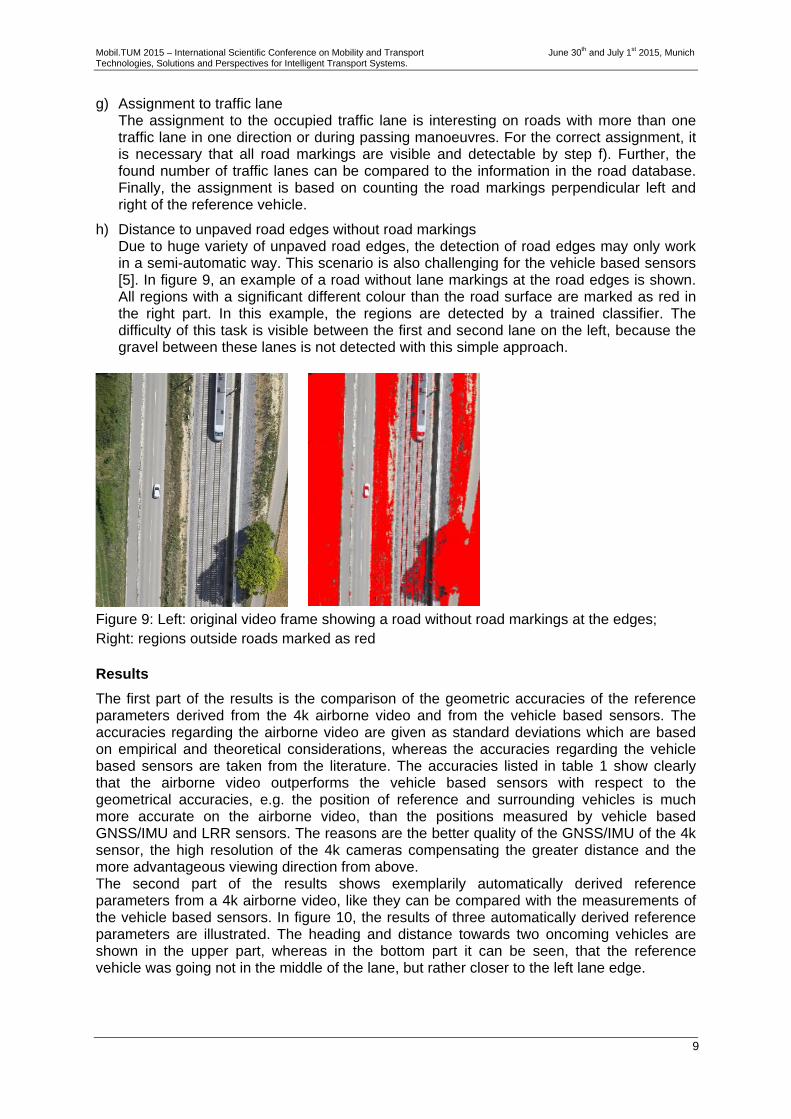
h) Distance to unpaved road edges without road markings Due to huge variety of unpaved road edges, the detection of road edges may only work in a semi-automatic way. This scenario is also challenging for the vehicle based sensors [5]. In figure 9, an example of a road without lane markings at the road edges is shown. All regions with a significant different colour than the road surface are marked as red in the right part. In this example, the regions are detected by a trained classifier. The difficulty of this task is visible between the first and second lane on the left, because the gravel between these lanes is not detected with this simple approach.
Figure 9: Left: original video frame showing a road without road markings at the edges; Right: regions outside roads marked as red
Results
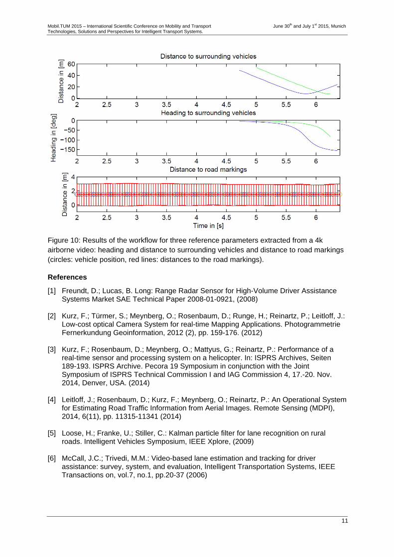
The first part of the results is the comparison of the geometric accuracies of the reference parameters derived from the 4k airborne video and from the vehicle based sensors. The accuracies regarding the airborne video are given as standard deviations which are based on empirical and theoretical considerations, whereas the accuracies regarding the vehicle based sensors are taken from the literature. The accuracies listed in table 1 show clearly that the airborne video outperforms the vehicle based sensors with respect to the geometrical accuracies, e.g. the position of reference and surrounding vehicles is much more accurate on the airborne video, than the positions measured by vehicle based GNSS/IMU and LRR sensors. The reasons are the better quality of the GNSS/IMU of the 4k sensor, the high resolution of the 4k cameras compensating the greater distance and the more advantageous viewing direction from above. The second part of the results shows exemplarily automatically derived reference parameters from a 4k airborne video, like they can be compared with the measurements of the vehicle based sensors. In figure 10, the results of three automatically derived reference parameters are illustrated. The heading and distance towards two oncoming vehicles are shown in the upper part, whereas in the bottom part it can be seen, that the reference vehicle was going not in the middle of the lane, but rather closer to the left lane edge.
Mobil.TUM 2015 – International Scientific Conference on Mobility and Transport June 30th and July 1st 2015, Munich Technologies, Solutions and Perspectives for Intelligent Transport Systems.
10
Airborne video* Vehicle based sensors Absolute position of reference vehicle
<0.35m Depends mainly on DEM quality
<3m Assume basic GNSS/IMU quality
Absolute speed and heading of reference car
<0.3km/h Averaged over 10 frames (=0.4s)
<0.2km/h Assume basic GNSS/IMU quality
<1° Heading <3° Heading
Absolute position of surrounding vehicle
<0.65m Depends mainly on DEM quality
Not measured directly.
Relative distance/direction to surrounding vehicle
<0.04m Relative distance <0.2m LRR distance2
<1° Direction (>20m) <4° LRR direction
Absolute speed of surrounding vehicle
<0.3km/h Averaged over 10 frames (=0.4s)
Not measured directly.
Relative speed and heading of surrounding vehicle
<0.6km/h Rel. speed <0.2km/h LRR speed
<1° Heading
Relative distance to road markings
<0.04m Depends on the extraction accuracy
<0.13m Extraction from the front video sensor [6]
Relative distance to road database segment
<0.35m Depends mainly on the accuracy of the absolute vehicle position
<3m Assume basic GNSS/IMU quality
Accuracy of time <10ms Absolute w.r.t. GNSS time
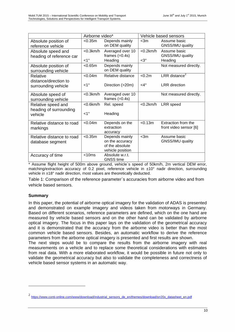
* Assume flight height of 500m above ground, vehicle`s speed of 50km/h, 2m vertical DEM error, matching/extraction accuracy of 0.2 pixel, reference vehicle in ±10° nadir direction, surrounding vehicle in ±18° nadir direction, most values are theoretically deducted.
Table 1: Comparison of the reference parameter`s accuracies from airborne video and from vehicle based sensors.
Summary
In this paper, the potential of airborne optical imagery for the validation of ADAS is presented and demonstrated on example imagery and videos taken from motorways in Germany. Based on different scenarios, reference parameters are defined, which on the one hand are measured by vehicle based sensors and on the other hand can be validated by airborne optical imagery. The focus in this paper lays on the validation of the geometrical accuracy and it is demonstrated that the accuracy from the airborne video is better than the most common vehicle based sensors. Besides, an automatic workflow to derive the reference parameters from the airborne optical imagery is presented and first results are shown. The next steps would be to compare the results from the airborne imagery with real measurements on a vehicle and to replace some theoretical considerations with estimates from real data. With a more elaborated workflow, it would be possible in future not only to validate the geometrical accuracy but also to validate the completeness and correctness of vehicle based sensor systems in an automatic way.
2 https://www.conti-online.com/www/download/industrial_sensors_de_en/themes/download/srr20x_datasheet_en.pdf
Mobil.TUM 2015 – International Scientific Conference on Mobility and Transport June 30th and July 1st 2015, Munich Technologies, Solutions and Perspectives for Intelligent Transport Systems.
11
Figure 10: Results of the workflow for three reference parameters extracted from a 4k airborne video: heading and distance to surrounding vehicles and distance to road markings (circles: vehicle position, red lines: distances to the road markings).
References
[1] Freundt, D.; Lucas, B. Long: Range Radar Sensor for High-Volume Driver Assistance Systems Market SAE Technical Paper 2008-01-0921, (2008)
[2] Kurz, F.; Türmer, S.; Meynberg, O.; Rosenbaum, D.; Runge, H.; Reinartz, P.; Leitloff, J.:
Low-cost optical Camera System for real-time Mapping Applications. Photogrammetrie Fernerkundung Geoinformation, 2012 (2), pp. 159-176. (2012)
[3] Kurz, F.; Rosenbaum, D.; Meynberg, O.; Mattyus, G.; Reinartz, P.: Performance of a
real-time sensor and processing system on a helicopter. In: ISPRS Archives, Seiten 189-193. ISPRS Archive. Pecora 19 Symposium in conjunction with the Joint Symposium of ISPRS Technical Commission I and IAG Commission 4, 17.-20. Nov. 2014, Denver, USA. (2014)
[4] Leitloff, J.; Rosenbaum, D.; Kurz, F.; Meynberg, O.; Reinartz, P.: An Operational System
for Estimating Road Traffic Information from Aerial Images. Remote Sensing (MDPI), 2014, 6(11), pp. 11315-11341 (2014)
[5] Loose, H.; Franke, U.; Stiller, C.: Kalman particle filter for lane recognition on rural
roads. Intelligent Vehicles Symposium, IEEE Xplore, (2009) [6] McCall, J.C.; Trivedi, M.M.: Video-based lane estimation and tracking for driver
assistance: survey, system, and evaluation, Intelligent Transportation Systems, IEEE Transactions on, vol.7, no.1, pp.20-37 (2006)