validation of results of smart grid protection through
TRANSCRIPT
University of South FloridaScholar Commons
Graduate Theses and Dissertations Graduate School
October 2018
Validation of Results of Smart Grid Protectionthrough Self-HealingFelipe Framil AssumpçãoUniversity of South Florida, [email protected]
Follow this and additional works at: https://scholarcommons.usf.edu/etd
Part of the Electrical and Computer Engineering Commons
This Thesis is brought to you for free and open access by the Graduate School at Scholar Commons. It has been accepted for inclusion in GraduateTheses and Dissertations by an authorized administrator of Scholar Commons. For more information, please contact [email protected].
Scholar Commons CitationAssumpção, Felipe Framil, "Validation of Results of Smart Grid Protection through Self-Healing" (2018). Graduate Theses andDissertations.https://scholarcommons.usf.edu/etd/7468

Validation of Results of Smart Grid Protection through Self-Healing
by
Felipe Framil Assumpção
A thesis submitted in partial fulfillment of the requirements for the degree of
Master of Science in Electrical Engineering Department of Electrical Engineering
College of Engineering University of South Florida
Co-Major Professor: Ralph Fehr, Ph.D. Co-Major Professor: Wilfrido A. Moreno, Ph.D.
Elias K. Stefanakos, Ph.D.
Date of Approval: October 17, 2018
Keywords: Traditional power grid, Overcurrent Relay, Directional protection, Differential transformer relay protection
Copyright © 2018, Felipe Framil Assumpção

DEDICATION
I dedicate this work to my family, to Dr. Ralph Fehr, Dr. Wilfrido A. Moreno, Dr. Elias K. Stefanakos,
and all professors of the University of South Florida.

ACKNOWLEDGMENTS
I would like to thank Professor Dr. Ralph Fehr, Dr. Wilfrido A. Moreno, Dr. Elias K. Stefanakos for
all the professor of University of South Florida guidance and advice throughout my study.
I would like to thank all my friends and family for their support.

i
TABLE OF CONTENTS
LIST OF TABLES ...................................................................................................................................ii
LIST OF FIGURES ................................................................................................................................iii
ABSTRACT ......................................................................................................................................... iv
CHAPTER 1: INTRODUCTION................................................................................................................ 1 1.1 Theme Lining .................................................................................................................... 1 1.2 Identified Conflict.............................................................................................................. 1 1.3 Objective .......................................................................................................................... 1
CHAPTER 2: TYPES OF PROTECTION ..................................................................................................... 2 2.1 Protection Information ...................................................................................................... 2 2.2 Zone of Protection ............................................................................................................ 3 2.3 Overcurrent Relay Protection............................................................................................. 3 2.4 Directional Relay Protection .............................................................................................. 5 2.5 Transformer Differential Relay Protection........................................................................... 5 2.6 Self-healing Smart Grid ...................................................................................................... 6
CHAPTER 3: SIMULATION STUDIES AND RESULTS ................................................................................. 8 3.1 IEEE-9 Bus System ............................................................................................................. 8 3.2 IEEE-14 Bus System ......................................................................................................... 12
CHAPTER 4: CONCLUSION ................................................................................................................. 15
REFERENCES ..................................................................................................................................... 16

ii
LIST OF TABLES
Table 3.1 Tripping Sequences When a Fault Occurs Between Buses ..................................................... 12
Table 3.2 Tripping Sequences for Transformers Faults ....................................................................... 12
Table 3.3 Tripping Sequences for Transformers Faults ........................................................................ 14
Table 3.4 Tripping Sequences When a Fault Occurs Between Buses ..................................................... 14

iii
LIST OF FIGURES
Figure 2.1 Representation of Overcurrent Relay ................................................................................... 4
Figure 3.1 IEEE-9 Bus Electrical Power Network .................................................................................... 8
Figure 3.2 IEEE-9 Bus Power Bus Analysis Simulation ............................................................................ 9
Figure 3.3 IEEE-9 Bus Overcurrent Protection Simulation Buses 4 & 6 .................................................... 9
Figure 3.4 IEEE-9 Bus Overcurrent Protection Simulation Remaining Buses .......................................... 10
Figure 3.5 IEEE-9 Bus Protection External Simulation Transformer 1 .................................................... 10
Figure 3.6 IEEE-9 Bus Internal Protection Simulation Transformer 1..................................................... 11
Figure 3.7 IEEE-9 Bus Protection External Simulation Transformer 2 & 3 .............................................. 11
Figure 3.8 IEEE-9 Bus Internal Protection Simulation Transformer 2 & 3............................................... 11
Figure 3.9 IEEE-14 Bus Electrical Power Network ................................................................................ 13
Figure 3.10 IEEE-14 Bus Overcurrent Protection Simulation Buses 1 H_1 & 5 H_5 ................................. 13

iv
ABSTRACT
This is a verification of the results of “Smart Grid Protection through Self -Healing” from the
publication of Chathurika Chandraratne, et al., that proposes a protection solution for the smart grid. The
paper used as reference has as the main focus on three different protections; directional overcurrent
protection, overcurrent protection, and transformer protection, which are validated through ETAP
software simulation of IEEE- 9 bus and 14 bus electrical power systems, the same used by the author. It
was validated after repeated simulation, that just as intended, self-healing increases system agility, and it
helped prevent false-tripping14 bus electrical power systems.

1
CHAPTER 1: INTRODUCTION
1.1 Theme Lining
This paper is based on the publication “Smart Grid Protection through Self-Healing” by Chathurika
Chandraratne, R.T. Naayagi, Thillainathan Logenthiran [1].
The perceived importance of the theme explored by Chandraratne et al. for the evolution of
power grid systems throughout economies of all development stages, especially for its self -sustainability
and reliability, is the key motivator for the validation of the processes, seeking to ensure its efficacy when
tested and applied to different locations.
1.2 Identified Conflict
It was noted that the original publication from the Newcastle University in Singapore, did not
present a detailed report of the process that leads to the results and conclusion. Which is the reason for
which this document is made. The simulations used in the reference text did not seem to be numerous
enough, especially when referencing the 14 bus simulations, resulting in a less broad spectrum of
simulations.
1.3 Objective
Analyze and verify all the procedures that have been done during the IEEE-9 Bus Electric Power
System simulations, and create a complete protection utilizing sef-heling for the IEEE-14 Bus Electric
Power System simulations; and then verify how efficent the self-healing technic is for complex systems.

2
CHAPTER 2: TYPES OF PROTECTION
2.1 Protection Information
A power protection system was with objective keep the power system working by isolating any
fault that occurs in it the fast as possible utilizing protection devices [15].
The smart protection system provides advanced grid reliability analysis, failure protection, and
security and privacy protection [10]. Smart infrastructure permits the smart grid to recognize a smarter
management system and give the smarter protection system that is more effectively and efficiently to
support the failure of protection mechanisms, address cyber security issues and preserve privacy [1] [7].
Protective relays are a protective device that trip a circuit breaker when it detects fault, so it can
isolate it as fast as possible without affecting unrelated areas [15]. This prevents equipment damage due
to fault or overload and increase the system safety for people [11].
Relays can be divided into several types, by the protection characteristics. For example, the
overcurrent relay verifies the current to detect if it is not higher than the normal value, if so, it will cause
their respective circuit breaker to trip [4].
When selecting the protection solution, it is necessary to respect some requirements. The
protection solution must give the maximum protection in an effective cost, it must reliable, make it easy
to have a high-speed operation and isolate faults as fast as possible without compromising the operation
of the neighboring areas.
To have a good relay performance, some attributes, such as reliability, sensitivity, selectivity, and
speed are necessary. However, it is also important that a current transformer with a correct rate is
selected.

3
Current transformer is a device that current being measured in its primary and it produces a
proportional current in its secondary winding. [2]
2.2 Zone of Protection
A zone of protection can be defined as the zone that is protected by a relay, and if a fault occurs
inside the zone, the protective device will active to isolate the fault. These zones can be divided into two
types. The primary zone and the backup zone [2].
The primary protection zone relays are the first that will activate when a fault occurs, being the
first to isolate the fault [12]. The backup protection zone only actives in case the primary protection zone
fails to isolate the fault, be it by retripping the primary zone circuit breakers or by tripping the circuit
breaker nearest to the fault [13].
That’s why the backup protection can be divided into two types, local and remote. The local type’s
protection is located in the same zone as the fault, and the remote type’s protection is located in the
nearest zone where the fault occurs will trip only in that zone.
To protect the whole system, it is necessary to have overlapping zones in the neighboring parts
of the zones by doing that it’s possible to be sure that there is not any part of the system that is not
protected. However, by overlapping zones if a fault occurs in an area the is protected by two or more
zones all of them will by isolated, so to reduce this problem it is necessary to minimize the number of
overlapping zones as much as possible so it will not interrupt the power in unaffected zones.
2.3 Overcurrent Relay Protection
Overcurrent relay is as described by its name a relay that is designed to operate it detect more
current than the predetermined amount that was inputted in its settings and is mostly used as a
protection system in a radial distribution [1].
Figure 2.1 represents an overcurrent relay, where the I is the current in the line, I’ is the current
in the secondary side of the current transformer that is detected by the relay, and there will be a pick-

4
up current or threshold current represented by I pickup that corresponds to the value defined in the relay
setting.
Figure 2.1 Representation of Overcurrent Relay
When the overcurrent relay operates in its normal condition, it means that I’ is lower that I pickup,
and that the relay will not send a tripping signal to the circuit breaker that will stay closed.
If a fault occurs, it will cause I’ to be greater that I pickup, causing the relay to send a tripping signal
to the circuit breaker that will open and isolate the line.
For the system be protected, it is necessary for the relay to have a proper and accurate pick-up
and time-dial setting set based on the fault current and required operating time.
There are two categories of overcurrent relay, that are defined by its operating settings, they are
the instantaneous overcurrent relay and timed-overcurrent relay.
The instantaneous overcurrent relay, as the name suggests, is designed so there will be no time
in the operation when the current goes above the relay setting, causing the circuit breaker controlled by
it to trip, the operating time for this case can go as low as 16 milliseconds to as high as 0.1 seconds [ 5].

5
The time-overcurrent relay is designed so the operating time changes inversely related to
operating current, and three of these inverse characteristics are the most commonly used: inverse, very
inverse, and extremely inverse [3].
2.4 Directional Relay Protection
As per IEEE standard, the directional overcurrent relay can be represented by Relay 67 [16].
Directional relays utilize an additional polarizing source of voltage or current to differentiate from with
direction the fault occurred, allowing it to determinate if the fault occurred before or after where the
relay is placed, permitting the appropriate protective devices to operate inside or outside of the
protection zone.
The directional relay can be used for ground and phase faults, and it can utilize current, voltage
and the angle between them to achieve the protection, but to find the directional fault by comparing
the fault current, and the line current of the system, an intelligent electronic device is needed.
When there is a ground fault, the residual voltage is equal to three times the zero-sequence
voltage drop on the source impedance, and stays as zero when the voltages phases are balanced. Having
the possibility to cause a displacement from the residual current by the characteristic angle of the
impedance source [9]. To have a correct directional protection it is necessary to have its values calculated.
Cases of false tripping can occur on several occasions, one of them is when a distributed
generator is connected to the medium voltage feeder with an improper coordination and protection
modification, even though the circuit breaker will correctly trip in the short circuit fault, it will cause
circuit breaker of distributed generator to trip, even if it should not. This type of incorrect tripping is
common when the synchronous generation is used as a distributed generator source [1]. However, by
using directional protection, it can be fixed [6], since it identifies the direction in which the fault occurs,
compared to the relay’s location, setting to activate only when a fault occurs in one direction, and not in
the other direction.

6
2.5 Transformer Differential Relay Protection
As per IEEE standard, the differential transformer relay can be represented by Relay 87T [16].
Transformer differential relay is a relay that compares the current between the two sides of a
transformer, it makes use of Kirchhoff’s current law that states that the total of current entering is equal
to the total of the current existing the transformer when it is working correctly, and have the difference
of the input and output current greater that zero when there is a fault, casing the relay to activate [5].
This relay can also protect generators, large motors, lines, buses, and cables but is unable to protect the
equipment from external faults, and faults caused by overload [1].
2.6 Self-healing Smart Grid
Self-healing smart grids are systems composed by the sensor, automated controls and a software
that can utilize real-time distribution data to detect and isolate faults, and can reconfigure the distribution
network to reduce the number of customers impacted by a power outage [14] [8].
It is possible, by reconfiguring the protection equipment in the feeder, to isolate faults and re-
establish the power to several customers as fast as possible by changing to an alternative source or feeder,
by doing this, it is possible to increase the reliability of the system that is one of the objectives of the self-
healing. To reconfigure a system from one to five minutes that is the requirement for a typical self -healing
solution, a high bandwidth may be necessary [1].
Self-healing permits a system to identify if there are some parts of itself that is not working
correctly and make the necessary adjustments so it can be restored to a normal condition. Usually, self-
healing refers to controlling generator power output, reconfiguration and load shedding and its actions
are multi-objective, nonlinear optimization problem with several limitations. To solve these problems, it
is necessary to develop an advanced algorithm using artificial intelligence techniques and multi -agent
systems.

7
Smart grid restoration problems are extremely complex due to several challenges, like limited
capacities of distributed energy resources, bidirectional power flow, and mesh connected topologies.
The deployment of self-healing for the grid and for the consumers can be explained by distribution
automation, recloser and fault circuit indicators. Distribution automation automatically reroutes power
based on the generation level, fault conditions, and the load requirements. The communication feature
of smart grids facilitates intelligent decision making. When using a recloser in a normal grid, and a fault
occurs, the circuit breaker will open and after sometime, the circuit breaker will reclose to check whether
the fault still persists in the system. In a smart grid, the recloser will report the failure over the
communication network and wait for further instructions. Fault Circuit Indicators monitor the power lines
and feeders by constantly sensing the current, voltage and fault conditions. In the case of a fault, it will
communicate this information immediately for corrective actions to take place.

8
CHAPTER 3: SIMULATION STUDIES AND RESULTS
Utilizing ETAP software to do the simulation of IEEE-9 bus and IEEE-14 bus electrical power
networks. The simulations used the load flow analysis, short circuit analysis and lastly, implemented
protection solutions were tested. The system protection in this simulation used differential transformer
relay protection, directional overcurrent relay protection, and overcurrent relay protection.
3.1 IEEE-9 Bus System
Figure 3.1 IEEE-9 Bus Electrical Power Network
Figure 3.1 shows the IEEE-9 bus electrical power network in ETAP. The IEEE-9 bus composed of
three generators, three two-winding power transformers, nine buses, three loads and six lines. Since there
are three generators powering the system there is a three-way electricity flow.
9
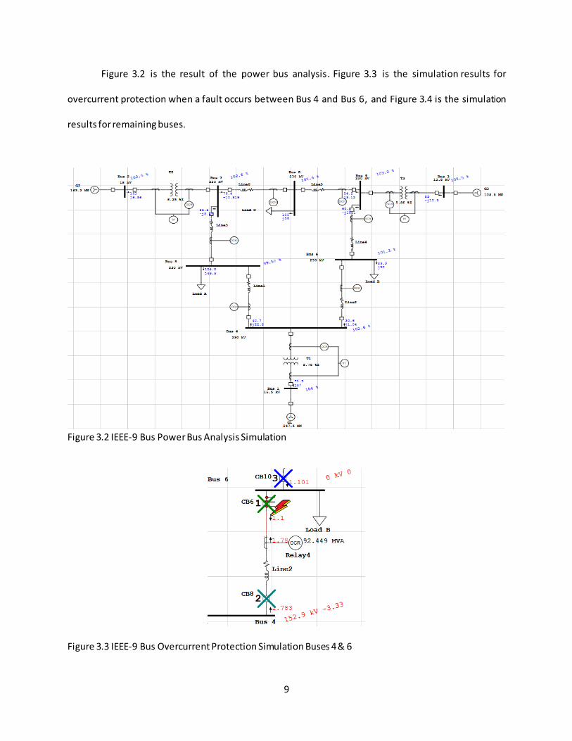
Figure 3.2 is the result of the power bus analysis. Figure 3.3 is the simulation results for
overcurrent protection when a fault occurs between Bus 4 and Bus 6, and Figure 3.4 is the simulation
results for remaining buses.
Figure 3.2 IEEE-9 Bus Power Bus Analysis Simulation
Figure 3.3 IEEE-9 Bus Overcurrent Protection Simulation Buses 4 & 6
10
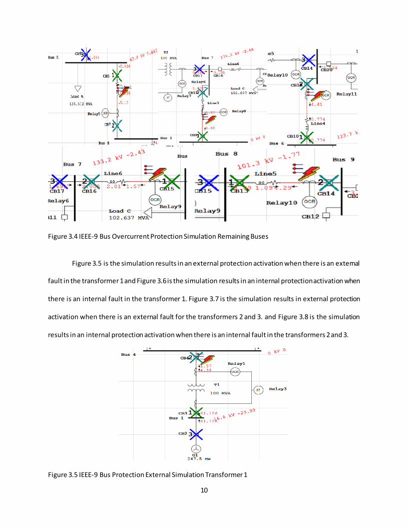
Figure 3.4 IEEE-9 Bus Overcurrent Protection Simulation Remaining Buses
Figure 3.5 is the simulation results in an external protection activation when there is an external
fault in the transformer 1 and Figure 3.6 is the simulation results in an internal protection activation when
there is an internal fault in the transformer 1. Figure 3.7 is the simulation results in external protection
activation when there is an external fault for the transformers 2 and 3. and Figure 3.8 is the simulation
results in an internal protection activation when there is an internal fault in the transformers 2 and 3.
Figure 3.5 IEEE-9 Bus Protection External Simulation Transformer 1

11
Figure 3.6 IEEE-9 Bus Internal Protection Simulation Transformer 1
Figure 3.7 IEEE-9 Bus Protection External Simulation Transformer 2 & 3
Figure 3.8 IEEE-9 Bus Internal Protection Simulation Transformer 2 & 3
In order to protect the transformer of external faults, an overcurrent is combined with a Relay
that causes three breakers to trip; those breakers being two primary protection breakers and one as a
backup in the transformer 1’s case. The primary protection being the breakers CB3 and CB4, with the CB2
being the backup.
12
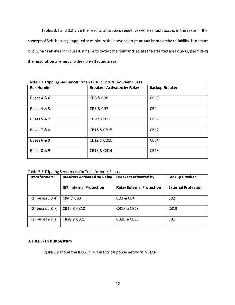
Tables 3.1 and 3.2 give the results of tripping sequences when a fault occurs in the system. The
concept of Self-healing is applied to minimize the power disruption and improve the reliability. In a smart
grid, when self-healing is used, it helps to detect the fault and isolate the affected area quickly permitting
the restoration of energy to the non-affected areas.
Table 3.1 Tripping Sequences When a Fault Occurs Between Buses
Bus Number Breakers Activated by Relay Backup Breaker
Buses 4 & 6 CB6 & CB8 CB10
Buses 4 & 5 CB5 & CB7 CB9
Buses 5 & 7 CB9 & CB11 CB17
Buses 7 & 8 CB16 & CB15 CB17
Buses 6 & 9 CB12 & CB10 CB14
Buses 8 & 9 CB13 & CB14 CB15
Table 3.2 Tripping Sequences for Transformers Faults Transformers Breakers Activated by Relay
(87) Internal Protection
Breakers activated by
Relay External Protection
Backup Breaker
External Protection
T1 (buses 1 & 4) CB4 & CB3 CB3 & CB4 CB2
T2 (buses 2 & 7) CB17 & CB18 CB17 & CB18 CB19
T3 (buses 9 & 3) CB20 & CB21 CB20 & CB21 CB1
3.2 IEEE-14 Bus System
Figure 3.9 shows the IEEE-14 bus electrical power network in ETAP.

13
Figure 3.9 IEEE-14 Bus Electrical Power Network
This system consists of five generators, 14 buses, six lines, 11 loads and three two-winding power
transformers. It has five ways of energy flow as it has five generators to power the system. The best kind
of protection to be used in this system, in which one bus has several connections to other buses, is the
directional overcurrent protection, since directional protection can control which direction the circuit
breaker should trip when a fault occurs. In this simulation, the system is protected by employing the self-
healing concept. Figure 3.10 and when the fault occurs between the buses Bus1 H_1 and Bus 5 H_5 trips
the circuit breakers CB3 and CB6
Figure 3.10 IEEE-14 Bus Overcurrent Protection Simulation Buses 1 H_1 & 5 H_5

14
The results of the transformer protection obtained from the simulation are shown in Table 3.3
and the activation sequence for between buses on table 3.4.
Table 3.3 Tripping Sequences for Transformers Faults Transformer Breakers activated by Relay
5_6 CB14 & CB13
4_9 CB27 & CB26
4_7 CB28 & CB29
Table 3.4 Tripping Sequences When a Fault Occurs Between Buses Bus Number Breakers Activated by Relay
Buses 1 & 5 CB3 & CB6
Buses 1 & 2 CB2 & CB4
Buses 2 & 5 CB7 & CB8
Buses 2 & 4 CB10 & CB18
Buses 2 & 3 CB11 & CB20
Buses 3 & 4 CB22 & CB23
Buses 4 & 5 CB16 & CB17
Buses 6 & 12 CB51 & CB57
Buses 6 & 13 CB50 & CB53
Buses 6 & 11 CB49 & CB43
Buses 7 & 8 CB30 & CB31
Buses 7 & 9 CB33 & CB34
Buses 9 & 14 CB37 & CB39
Buses 9 & 10 CB38 & CB40
Buses 10 & 11 CB43 & CB42
Buses 12 & 13 CB56 & CB55
Buses 13 & 14 CB52 & CB46

15
CHAPTER 4: CONCLUSION
It was possible, after reproducing the paper “Smart Grid Protection through Self-Healing” from
Chathurika et al. [1], and further simulating the IEEE-14 bus electrical power, to verify that the Self-healing
technic can be used in complex systems and it that increases their reliability.

16
REFERENCES
[1] Chathurika Chandraratne, R.T. Naayagi, Thillainathan Logenthiran, “Smart Grid Protection through Self-Healing”, 2017 IEEE Innovative Smart Grid Technologies.
[2] Ralph Fehr, “Industrial power distribution”, Wiley, 2016.
[3] Claudio Sergio Mardegan, Rasheek Rifaat, “Considerations in Applying IEEE Recommended Practice for Protection Coordination in Industrial and Commercial Power Systems—Part I”, IEEE Transactions on Industry Applications, vol.52, no.5, pp. 3705-3713, 2016.
[4] Distribution System Feeder Overcurrent Protection, GE Power management report-GET-6450, 1-21, Last accessed May 2017.
[5] Michael Stanbury, Zarko Djekic, “The Impact of Current-Transformer Saturation on Transformer Differential Protection”, IEEE Transactions on Power Delivery, vol.30, no.3, pp. 1278-1287, 2015.
[6] D. Novosel, M. Begovic, and V. Madan. Shedding light on blackouts. IEEE Power and Energy Magazine, Jan. 2004.
[7] J. Liu, Y. Xiao, S. Li, W. Liang, and C. L. Chen. Cyber security and privacy issues in smart grids. Communications Surveys & Tutorials, IEEE, 14(4):981–997, 2012.
[8] Muhammad Ramadan, Surian Raj, T. Logenthiran, R.T. Naayagi, W.L. Woo, “Self -healing Network Instigated by Distributed Energy Resources,” in proceedings of the 9th IEEE PES Asia-Pacific Power and Energy Engineering Conference, November 8-10, 2017, Bangalore, India.
[9] B.M.S. Muhammad Ramadan, T. Logenthiran, R.T. Naayagi, C. Su, “Accelerated Lambda Iteration Method for Solving Economic Dispatch with Transmission Line Losses Management,” in proceedings of IEEE PES Innovative Smart Grid Technologies (ISGT Asia) Conference, pp. 138-143, 2016, Melbourne, Australia.
[10] H. Farhangi., The path of the smart grid, IEEE Power and Energy Magazine, Vol.8, Issue.1, 2010.
[11] J. Zhang and Y. Dong. Preventing false trips of zone 3 protection relays in smart grid. Tsinghua Science and Technology, 20(2):142–154, 2015.
[12] S. Garlapati, H. Lin, S. Sambamoorthy, S. K. Shukla, and J. S. Thorp. Agent based superv ision of zone 3 relays to prevent hidden failure based tripping, 2010 First IEEE International Conference on Smart grid communications, pages 256–261. IEEE, 2010.
[13] Jiapeng Zhang, Yingfei Dong, “Power-Aware Communication Management for Reliable Remote Relay Protection in Smart Grid”, IEEE Power Systems Conference, pp.1-6, 2016.

17
[14] J. Gao, Y. Xiao, J. Liu, W. Liang, and C. L. P. Chen, “A survey of communication/networking in smart grids”, Future Generation Computer Systems, 28(2):391–404, 2012.
[15] Paul M. Anderson, “Power System Protection” 1st Edition, IEEE PRESS, 1999
[16] Applied Protective Relaying 1979 by Westinghouse Electric Corporation, 2nd Printing, "Appendix II, Electrical Power System Device Numbers and Functions" as adopted by IEEE standard and incorporated in American Standard C37.2-1970.