vallurupalli nageswara rao vignana jyothi institute … · 2019-07-13 · page | 2 (i) assemble...
TRANSCRIPT

VALLURUPALLI NAGESWARA RAO VIGNANA JYOTHI INSTITUTE OF ENGINEERING AND TECHNOLOGY
DEPARTMENT OF MECHANICAL ENGINEEERING
IV B.TECH. I SEMESTER
QUESTION BANK
Estd.1995

Page | 1
DEPARTMENT OF MECHANICAL ENGINEEERING
(5ME15) FINITE ELEMENT METHOD
UNIT-I FUNDAMENTAL CONCEPTS-ONE DIMENSIONAL PROBLEM
Part – A (2 Marks)
1. Mention any two significant properties of global stiffness matrix [K]?
2. What is the size of global stiffness matrix size for 3 node bar element?
3. Explain Strain displacement relations for plane stress element?
4. What is a shape function. Explain its significance?
5. Write a note on product development by AM?
6. State the principle of minimum potential energy.
7. What are the properties of stiffness matrix?
8. What is the basic difference of Rayleigh –Ritz method and Weighted residual
method.
9. State the stress strain relation for plane stress problem?
10. State the stress strain relation for plane strain problem?
11. Draw the variation of shape functions for 2-noded bar element?
12. Discuss the Advantages and Disadvantages of FEM over classical Finite
Difference Method
Part – B (10 Marks)
1. State and explain the equilibrium equations for solving the solid mechanics
problems..
2. Explain with the help of examples the solution of a boundary value problem by
(i) Rayleigh –Ritz method (ii) Weighted residual method.
3. An axial load P = 350 X 103 N is applied at 25 0C to the rod shown in Figure 1. The
rod is discretized using 1D FEM. The temperature is then raised to 65 0C.
Estd.1995
VALLURUPALLI NAGESWARA RAO VIGNANA JYOTHI
INSTITUTE OF ENGINEERING AND TECHNOLOGY An Autonomous Institute, NAAC Accredited with ‘A++’ Grade
NBA Accredited CE, EEE, ME, ECE, CSE, EIE, IT - B.Tech Programs
Approved by AICTE, New Delhi, Affiliated to JNTUH
Recognized as “College with Potential for Excellence” by UGC

Page | 2
(i) Assemble stiffness and force matrices (ii) Determine nodal displacements and
element stresses.
4. For the three stepped bar shown in fig. 2, the fits snugly between the rigid walls at
room temperature. The temperature is then raised by 300C. Determine the
displacements at nodes 2 and 3, stresses in the three sections.
5. Find the displacement of the midpoint of the rod shown in figure 1 by the following
approaches
a) Rayleigh–Ritz method and b) Galerkin‟s method

Page | 3
6. Consider the differential equation along with the initial condition
, u(0) = 1. Solve this using Galerkin‟s method assuming an
initial approximation u = a + bx + cx2.

Page | 4
UNIT-II TRUSSES TWO-DIMENSIONAL PROBLEMS USING CONSTANT STRAIN TRIANGLES
Part – A (2 Marks)
1. Explain banded matrix and mention its order?
2. What is the physical significance of Jacobian and explain for 2 dimensional case?
3. How many number of nodes in a basic triangular element.
4. What is higher order element?
5. What is frame element?
6. Explain Strain displacement relations for plane stress element?
7. Draw the basic truss element?
8. What is Constant Strain Triangle (C S T)? Explain its applications.
9. Why the element is called constant strain triangle?
10. State general expressions for stiffness matrix and load vector due to body force
and surface force.
11. Derive the shape functions for 3-noded triangular element from Lagrange‟s
formula.
12. Draw the variation of shape functions for 3-noded triangular element?
Part – B (10 Marks)
1. Estimate the displacement vector, strains, stresses and reactions in the truss
structure shown below in figure.1 Take A = 1000 mm2 and E = 200 GPa

Page | 5
2. Determine the stiffness matrix, stresses and reactions in the truss structure shown in
Figure
3. The nodal coordinates of a triangular element are 1(1,3), 2(5,3) and 3(4,6). At a
point p inside the element, the x-coordinates is 3.3 and the shape function N1 =
0.3. Determine the shape functions and y-coordinates of the point P.
4. Consider the four-bar truss shown in figure 5. Consider E = 200 GPa and Ae = 100
mm2 for all elements. Complete the following:
(a) Determine the element stiffness matrix for each element.
(b) Assemble the structural stiffness matrix K for the entire truss.
(c) Find the nodal displacements, the stresses in each element.
(d) Calculate the reaction forces.
(e) Comment on thermal loading if T= 30 C and α = 6x10⁻⁶/C.

Page | 6
5. For the two-bar truss shown in figure 6 , determine the displacements of node 1 and
the stress in elements.
6. For the triangular element shown in figure 7, obtain the strain–displacement relation
matrix B and determine the strains x, y, and xy.

Page | 7
UNIT-III TWO-DIMENSIONAL ISOPARAMETRIC ELEMENTS AND NUMERICAL INTEGRATION
Part – A (2 Marks)
1. Represent the quadrilateral element with degree of freedom. Write the
displacement vector.
2. Write shape functions for four noded quadrilateral element?
3. Obtain consistent mass matrix for 1D bar element.
4. What is higher order element?
5. What is meant by isoperimetric element?
6. What is meant by sub parametric and super parametric elements?
7. What are the convergence and compatibility requirements for iso-parametric
elements
8. Write the Gaussian quadrature formula for numerically evaluating a one
dimensional integral with n-point approximation.
9. Distinguish Eigen values and Eigen vectors.
10. Differentiate consistent and lumped mass matrix.
11. Draw four node quadrilateral element and show the displacement vectors.
Part – B (10 Marks)
1. What is Iso-parametric formulation? Derive the shape functions for a quadrilateral
element?
2. Write a short note on higher order elements.
3. Find the natural frequencies and modes of vibration for the following cases:
• One element cantilever beam
• Two element cantilever beam by taking advantage of the symmetry about mid
point.
4. Determine the natural frequencies of simply supported beam shown in fig. Assume
the Young‟s Modulus as 200 GPa and density as 7800 kg/m3

Page | 8
5. Evaluate the integral ( ) ∫ ( )
Using Gaussian Quadrature and
show that the result is exact. Brief about strength, Weakness and applications of
SGC?
6. Solve the integral with the limits -1 to + 1 for the function I = 8x+4 x2 + 3x
3 + 4ex
using Gaussian Quadrature method and compare with the exact solution by 1
and 2 point approximations.
7. Derive element stiffness matrix for quadratic element, body force vector and
traction vector?
8. Determine the eigen values and eigen vectors for the bar of length 2m fixed at
one end, subjected to undamped free vibration using consistent mass for
translation DOF with E = 200GPa, ρ = 7500kg/m3.

Page | 9
(5ME16) CAD/CAM
UNIT-I INTRODUCTION COMPUTER GRAPHICS
Part – A (2 Marks)
1. What is design process?
2. Define synthesis.
3. What is meant by analysis?
4. Define optimization.
5. Explain the characteristics of concurrent engineering.
6. What is CAD?
7. What are the factors considered for selecting CAD?
8. Write the benefits of CAD.
9. Define Computer Graphics.
10. What is transformation? List its types.
11. Define Translation.
12. What is homogeneous coordinate representation?
13. Write the applications of homogeneous coordinate representation.
14. Write the features needed to be satisfied for line drawing algorithm.
15. Define clipping.
16. What is viewing transformation?
Part – B (10 Marks)
1. Explain product cycle model with flow chart.
2. Describe various stages of design process.
3. What are the various display devises that are used for displaying graphic
information? Discuss the merits and demerits of each one.
4. a) Explain about CAD/CAM hardware.
b) Explain about different display devices.
5. Explain 2D and 3D transformation with matrix
6. Explain the techniques involved in line drawing algorithm.

Page | 10
7. Briefly explain various methods of clipping.
8. The unit square with vertices A (1, 1), B (2, 1), C (2, 2), and D (1, 2) is
transformed in the following sequence.
i) Scaled about the origin by factors of 4 and 2 in the x- and y- directions.
ii) Rotated about point B through 90ْ
What are the coordinates of the vertices of transformed geometry?
9. Differentiate between Raster-scan technique and Random-scan technique.
10. Discuss the influence exerted by the computers on the manufacturing.
11. a) Explain about Cohen-Sutherland line clipping algorithm.
b) Write a brief note on output devices.

Page | 11
UNIT-II GEOMETRIC MODELING
Part – A (2 Marks)
1. How curves are represented?
2. What are synthetic curves?
3. What are Hermit curves?
4. How Hermitic curves can be modified?
5. What are the limitations of Hermitic curves?
6. What are the observations made in Bezier curve?
7. What are the advantages of B-spline curve?
8. What are rational curves?
9. What is surface modeling?
10. What are the techniques available for surface modeling?
11. List the advantages and disadvantages of CSG model.
12. What are the different modeling tools?
13. What is geometric modeling?
14. What is solid modeling?
15. What are the advantages of B-rep?
16. List the differences between Bezier curve and Hermite curve.
Part – B (10 Marks)
1. Explain Hermite curve with neat sketch?
2. Explain different types of Bezier Curves in detail. Explain its advantages and
limitations.
3. Explain B-spline curves and its characteristics. Explain its advantages and
limitations.
4. Describe surface modeling with neat sketch.
5. Describe construction of “Coons patch”. Explain its advantages and limitations.

Page | 12
6. The co-ordinates of four control points relative to a curve are given by P1(2,2,0),
P2(2,3,0),P3(3,3,0) and P4(3,2,0). Write the equation of Bezier curve. Also find the
co-ordinate pixels of the curve for U = 0,1/4,1/2,3/4,1. Also plot Bezier curve.
7. Explain the Bezier surface with its properties.
8. Explain the construction of B – Spline surface with neat sketch. Explain its
advantages and limitations.
9. Describe the CSG model with suitable example.
10. a) Write a short note on (i) Sweep surfaces and (ii) Lofted surfaces.
b) Write any five differences between Analytical surfaces and Synthetic surfaces.
11. What are the basic geometric commands used in drafting system? Explain with
examples.
12. a) What are the requirements of geometric models and explain the need of
geometric modeling.
b) What are the requirements of geometric models and explain the need of
geometric modeling.
13. What is Layering? Give some examples where the layering concept is useful. [7]
b) Give some examples where the Offsetting and Grid concepts are used with a
CAD drafting system.
14. a) Explain various display control commands in drafting and modeling systems.
b) Explain various editing commands in drafting and modeling systems.
15. a) Describe various commonly used primitives for solid modeling and explain the
Boolean operations.
b) Explain parametric and non parametric representation of the following
analytical curves
i) Lines ii) Circle iii) Ellipse iv) Parabola v) Hyperbola

Page | 13
UNIT-III COMPUTER NUMARICAL CONTROL & CNC PART PROGRAMMING
Part – A (2 Marks)
1. Define NC system?
2. What is MCU?
3. List out any four advantage of using NC?
4. what are the limitations of using NC?
5. What are all the problems encountered with NC system?
6. Define CNC?
7. Write the main functions of CNC?
8. What are the functions of diagnostic system in NC machine tools?
9. List the differences between NC and CNC system?
10. List the differences between open loop and closed loop control system?
11. Write the functions of DNC?
12. Define G02,G03 & G04
13. Explain the functions of codes G28 and M30.
14. List out some of the important NC languages.
15. What are the four statements used in APT language?
16. How can you represent an APT geometric statement?
17. List the motion command words used in achieving path commands.
18. What are the modifiers used with motion command words?
19. Write any four auxiliary statements
20. List any four post processor statements.

Page | 14
Part – B (10 Marks)
1. Write manual part program for the part shown in the following figure For each part
write two programs one to drill the holes and the other to perform milling. The part
material is low carbon steel and the cutters are HSS. Part thickness is 0.5 mm,
spindle speed is 1000 rpm and feed rate is 0.2 mm/rev.
2. Explain the structure of CNC machine tools.
3. Write the NC part program for the part shown in the following figure. For each part
write two programs one to drill the holes and the other to perform milling. The part
material is low carbon steel and the cutters are HSS. Part thickness is 0.5 mm,
spindle speed is 1000rpm and feed rate is 0.2 mm/rev.

Page | 15
4. What are the various types of tool magazines used in CNC machine tools? Give
their relative merits.
5. Explain different statements present in APT language.
6. What is Floating datum and Set Point in CNC part programming? Explain with an
example.
7. Write a short note on
(i) Absolute and Incremental positioning system.
(ii) Fixed and Floating zero method.
8. Define Numerical Control. Explain the elements of NC in detail.
9. Explain about the features of machining center.
10. State the advantages and disadvantages of Computer Numerical Control.
11. Write a part programme for the component shown in figure All the dimensions are
in mm only.
12. a) Differentiate between NC and CNC machines.
b) Write a short note on the Miscellaneous functions in part programming.
13. Briefly discuss the data required for Computer Assisted Part Programming.
b) State the advantages and disadvantages of Numerical Control.
14. Briefly describe the CNC machining centers. With the help of a diagram
differentiate between the operations of canned cycles G81 and G83.

Page | 16
15. Explain the role of a Part Programmer in Manual Programming Method and
Computer Assisted Part Programming Method.

Page | 17
(5ME17) OPERATIONS RESEARCH
UNIT-I INTRODUCTION
Part – A (2 Marks)
1. Define Operations Research.
2. What is the difference between feasible solution and basic feasible solution?
3. State any three limitations of O.R.
4. Write the applications of Operations Research
5. Write the steps of OR?
6. Define slack variable and surplus variables..
7. Write the general form of LPP with an example
8. State the different types of models used in Operations Research
9. Define artificial variable and slack variable
10. Write the standard form of LPP with an example
11. What are the different phases of Operation Research
12. What is meant by degenerate in simplex problems?
13. What is slack variable?
14. What is a non basic variable?
Part – B (10 Marks)
1. Solve the following Linear Programming Problem by simplex method
Maximize Z=6X1+ 4X2
Subject to the conditions
2X1 + 3X2 ≤ 100
4X1 + 2X2 ≤ 120 and
X1, X2 ≥ 0
2. Solve the following Linear Programming Problem by graphical method.
Maximize Z=3X1+ 5X2
Subject to the conditions
X1 ≤ 4

Page | 18
2X2 ≤12
3X1 + 2X2 ≤ 18 and
X1 , X2 ≥ 0
3. Write the DUAL of the given LPP
Min.Z=3X1-2X2+4X3, subject to the constraints
3X1+5X2+4X3≥7, 6X1+X2+3X3 ≤ 4, 7X1-2X2-X3=10,
4. Solve the simplex problem
Minimize the Z=600X1+500X2
Subjected to
2X1+X2 ≥ 80
X1+2X2 ≥ 60
5. Solve the following Linear Programming Problem using simplex method.
Minimize Z=5x+4y+4z
Subject to
x+y+z=100, x≥20, y≥30, z≤40 and x, y, z ≥0
6. Solve the following LPP by Big M method.
Maximize Z=5X1+ 8X2
Subject to the conditions
3X1 + 2X2 ≥3
X1 + 4X2 ≥ 4 and X1 + X2 ≤ 5
X1, X2 ≥ 0
7. Solve the following LPP by dynamic programming method.
Maximize Z=2X1+5X2
Subject to 2X1+X2≤ 43
2X2≤46 and X1, X2 ≥ 0
8. Solve the following LPP by Big M method.
Maximize Z=2X1+ 3X2
Subject to the conditions
X1 + X2 ≥2 and X1 + 2X2 ≤ 8
X1, X2 ≥ 0

Page | 19
UNIT-II TRANSPORTATION PROBLEMS
Part – A (2 Marks)
1. Write the other name for Vogels Approximation Method used to find an initial
solution to a given Transportation Problem
2. What is the difference between a Transportation Problem and an Assignment
Problem?
3. Explain No Passing Rule in connection with a sequencing problem
4. What is North-West corner rule?
5. Write the methods of finding initial basic feasible solutions to solve the
Transportation problems
6. Explain the travelling salesmen problem
7. What is degeneracy in transportation problems
8. What is Least cost method in the transportation problems
9. What is Unbalanced Transportation Problem?
10. Define Elapsed time in sequencing problems
11. What is a unbalanced transportation problem
Part – B (10 Marks)
1. Use Least cost method to obtain an initial basic feasible solution of the following
Transportation Problem and find its cost.
Ware Houses
Factory W X Y Z Supply
A 11 13 17 14 250
B 16 18 14 10 300
C 21 24 13 10 400
Demand 200 225 275 250

Page | 20
2. Find the total cost by penalty method
F▼
D►
D1 D2 D3 D4 D5 Capaci
ty
F1 1 9 13 36 51 50
F2 24 12 16 20 1 100
F3 14 33 1 23 23 150
Demand 100 70 50 40 40
3. Use Vogel‟s approximation method to obtain an initial basic feasible solution to
the following Transportation Problem & also find the optimal solution.
Ware House
Factory W X Y Z Supply
A 11 13 17 14 250
B 16 18 14 10 300
C 21 24 13 10 400
Demand 200 225 275 250
4. Solve the Assignment Problem represented by the matrix.
1 2 3 4 5 6
A 9 22 58 11 19 27
B 43 78 72 50 63 48
C 41 28 91 37 45 33
D 74 42 27 49 39 32
E 36 11 57 22 25 18
F 3 56 53 31 17 28

Page | 21
5. Use Least cost method to obtain an initial basic feasible solution of the following
Transportation Problem and find its cost.
Ware Houses
Factory W X Y Z Supply
A 11 13 17 14 250
B 16 18 14 10 300
C 21 24 13 10 400
Demand 200 225 275 250
6. Find the sequence that minimizes the total elapsed time required to complete the
following tasks
Tasks→
Time on
machines↓
A B C D E F G
M-I 3 8 7 4 9 8 7
M-II 4 3 2 5 1 4 3
M-II 6 7 5 11 5 6 12
7. Solve the unbalanced Assignment Problem represented by the matrix
1 2 3 4 5 6
A 9 22 58 11 19 27
B 43 78 72 50 63 48
C 41 28 91 37 45 33
D 74 42 27 49 39 32

Page | 22
8. Find the sequence that minimizes the total elapsed time required to complete the
following tasks
Tasks→
Time on
machines↓
A B C D E F G
M-I 3 8 7 4 9 8 7
M-II 4 3 2 5 1 4 3
9. There are 5 Technicians who can work on 5 different machines having the same
configuration. The average time taken by each technician to make a job on
each machine is given in the following table. Assign one machine to a technician
so that total working time to make five jobs is minimum.
Machines
M1
M2
M3 M4 M5
Technicians
A 7 8 9 9 8
B 8 9 11 10 9
C 7 8 10 8 9
D 10 9 8 9 10
E 10 8 9 11 9
10. Find the optimal sequence for the following sequencing problems of four jobs and
five machines when passing is not allowed of which processing time(in hours) is
given below:
MACHINES

Page | 23
JOBS
M1 M2 M3 M4 M5
A 7 5 2 3 9
B 6 6 4 5 10
C 5 4 5 6 8
D 8 3 3 2 6
Page | 24
UNIT-III REPLACEMENT &THEORY OF GAMES
Part – A (2 Marks)
1. Define saddle point used in Game Theory.
2. What do you understand by Group Replacement Policy?
3. Write the principles of dominance applied in Game Theory.
4. Why replacement of equipment is required in an industry.
5. Define the two persons zero sum game.
6. Write the need of replacement of items in the real life?
7. What is Saddle point in Game Theory?
8. What is mixed strategy?
Part – B (10 Marks)
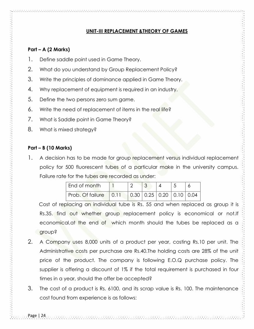
1. A decision has to be made for group replacement versus individual replacement
policy for 500 fluorescent tubes of a particular make in the university campus.
Failure rate for the tubes are recorded as under:
End of month 1 2 3 4 5 6
Prob. Of failure 0.11 0.30 0.25 0.20 0.10 0.04
Cost of replacing an individual tube is Rs. 55 and when replaced as group it is
Rs.35. find out whether group replacement policy is economical or not.If
economical,at the end of which month should the tubes be replaced as a
group?
2. A Company uses 8,000 units of a product per year, costing Rs.10 per unit. The
Administrative costs per purchase are Rs.40.The holding costs are 28% of the unit
price of the product. The company is following E.O.Q purchase policy. The
supplier is offering a discount of 1% if the total requirement is purchased in four
times in a year, should the offer be accepted?
3. The cost of a product is Rs. 6100, and its scrap value is Rs. 100. The maintenance
cost found from experience is as follows:

Page | 25
Year 1 2 3 4 5 6 7 8
Maintenance
cost (Rs)
100 250 400 600 900 1200 1600 2000
When should the product be replaced?
4. Find the most economic batch quantity of a product on a machine. The
production rate of the item on the machine is 200 pieces / day. The demand is
uniform at the rate of 100 pieces / day. The set-up cost is Rs.200 per batch and the
cost of holding one item in inventory is Rs.0.81 per day. How will be the batch
quantity varies if the machine production rate was infinite?
5. Determine the solution of the game and their strategies whose pay of matrix-A is
given below
PLAYER B
PLAYER
A
B1 B2 B3
A1 -4 6 3
A2 -3 -3 6
A3 2 -3 4
6. Solve the following 2x4 game by graphical method.
B
A
B1 B2 B3 B4
A1 3 3 4 0
A2 5 4 3 7

Page | 26
(5ME73) REFRIGERATION AND AIR CONDITIONING
UNIT-I INTRODUCTION TO REFRIGERATION:
Part – A (2 Marks)
1. Define ton of refrigeration.
2. What is refrigeration?
3. Sketch the Bell-Coleman cycle on P-v and T-S diagrams.
4. What is a refrigeration and list applications?
5. Explain need of refrigeration in air craft.
6. Give the chemical formula and names of the refrigerants R-22 and R-10.
7. Discuss desirable properties of a good refrigerant?
8. Draw T-S diagram of simple evaporative cooling system.
9. What are the desirable properties of ideal refrigerant?
10. List applications of air refrigeration system.
11. Represent simple boot strap refrigeration system on T –S diagram.
Part – B (10 Marks)
1. Refrigerator working on Bell-Coleman cycle operates between pressure limits
of 1.05 bar and 8.5 bar. Air is drawn from the cold chamber at 10C, compressed
and, then it is cooled to 30C before entering the expansion cylinder. The
expansion and compression follows the law Pv1.3 = Constant. Determine the
theoretical C.O.P of the system.
2. In a refrigerator working on Bell Coleman cycle the air enters compressor at 1 bar
and –10ºC and gets compressed up to 5.5 bar. Compressed air is cooled to 27ºC
at same pressure before being sent to expander for expansion up to 1 bar and
then passes through refrigerated space. Determine refrigeration capacity, hp
required to run compressor and COP of system if air flow rate is 0.8 kg/s.
3. The data refer to a reduced ambient air refrigeration system used for an aircraft
are: speed of air craft = 1500 km/hr, ambient pressure = 0.8 bar, ambient

Page | 27
temperature = 5°C, ram efficiency = 100%, pressure of cooled air leaving the first
cooling turbine = 0.8 bar, temperature of cooled air leaving the heat
exchanger = 100°C, pressure ratio of the main compressor = 3, pressure loss
between the outlet of second cooling turbine and the cabin = 0.1 bar, pressure in
the cabin = 1 bar, temperature in the cabin = 22°C, load in the cabin = 10 TR,
isentropic efficiency of compressor = 85%, isentropic efficiency of both cooling
turbines = 80%. Find
(a) Mass ftow of the air passing through the second cooling turbine.
(b) Quantity of ram air passing through the heat exchanger, if the rise in
temperature is limited to 80 K.
(c) COP of the system.
4. (a) What are the components of steam refrigeration plant and explain working of
each component? (b) List advantages and limitations of steam refrigeration
system?
5. (a) Sketch bootstrap type air craft refrigeration with neat diagram?
(b) What is sub-cooling and super heating? Explain with the help of diagram, why
is super heating considered to be good in certain cases?
6. The data refer to a reduced ambient air refrigeration system used for an aircraft
are: speed of air craft = 1500 km/hr, ambient pressure = 0.8 bar, ambient
temperature = 5°C, ram efficiency = 100%, pressure of cooled air leaving the first
cooling turbine = 0.8 bar, temperature of cooled air leaving the heat exchanger =
100°C, pressure ratio of the main compressor = 3, pressure loss between the outlet
of second cooling turbine and the cabin = 0.1 bar, pressure in the cabin = 1 bar,
temperature in the cabin = 22°C, load in the cabin = 10 TR, isentropic efficiency of
compressor = 85%, isentropic efficiency of both cooling turbines = 80%.
Find
(a) Mass ftow of the air passing through the second cooling turbine.
(b) Quantity of ram air passing through the heat exchanger, if the rise in
temperature is limited to 80 K.
(c) COP of the system.

Page | 28
7. An aircraft cooling system consists of a compressor, cooler and expansion turbine.
The compressor receives air at 1.2 bar and 600C from the engine supercharger. It is
compressed isentropically with an efficiency of 75% to 1.6 bar and cooled to 550C.
The air then expands isentropically through the turbine to 0.85 bar, the work
developed is used to drive the compressor. The turbine exhaust air is then sent to
the aircraft cabin for cooling. Determine
(a) Temperature of air at turbine exhaust and turbine efficiency.
(b) COP of the system
(c) Discuss desirable properties of Refrigerants

Page | 29
UNIT-II VAPOUR COMPRESSION REFRIGERATION & SYSTEM COMPONENTS
Part – A (2 Marks)
1. List out the various components of vapor compression refrigeration system.
2. Define COP of refrigerator and heat pump.
3. Sketch air refrigeration system on P-V and T –S Diagram.
4. Explain working principle evaporator and sketch any one type.
5. Explain working principle of vertex tube refrigeration.
6. Explain working of vapour compression refrigeration system with neat sketch.
7. What is need of condenser in refrigeration system?
8. Explain need of compound compression.
9. What is the effect of sub cooling on vapor compression refrigeration cycle?
Part – B (10 Marks)
1. A vapour compression cycle works on Freon-12 refrigerant with condensation
temperature of 40ºC and evaporator temperature of – 20ºC. Refrigeration effect
of 2.86 ton is desired from the cycle. The compressor runs with 1200 rpm and has
clearance volume of 2%. Considering compression index of 1.13, calculate (a) the
COP (b) the piston displacement in the reciprocating compressor used for
compression.
2. A vapour compression refrigerator works between the pressure limits of 60 bar and
25 bar. The working fluid is just dry at the end of the compression and there is no
undercooling of the liquid before the expansion valve. Determine:
I. C.O.P of the cycle and
II.
Capacity of the refrigerator if the fluid flow is at the rate of 5kg/min.
Saturation
temperat
ure (K)
Pressure
(B
ar)
Specific Enthalpy
(kJ/kg)
Specific entropy
(kJ/kg-k)
Liquid Vapour Liquid vapour

Page | 30
295 60 151.96 293.29 0.554 1.0332
261 25 56.32 322.58 0.226 1.2464
3. (a) Sketch bell Coleman cycle with schematic diagram and also show on T – S
diagram?
(b) A F-12 refrigeration machine works between the pressures of 9.9 and 3.3 bars.
The condition of the vapour leaving the compressor is 92% dry and there is under
cooling in the condenser. Determine the theoretical COP of the machine?
4. (a) Explain the method of improving the COP of vapour compression system?
(b) Draw neat sketch of multi compressor refrigeration system and Explain
5. (a) Explain the working of Electrolux with neat sketch?
(b) List Advantages and Disadvantages of Electrolux System? Explain about
multiple evaporators defrosting system?
6. (a) What is sub-cooling and super heating? Explain with the help of diagram, why is
super heating considered to be good in certain cases?
(b)A F-12 refrigeration machine works between the pressures of 9.9 and 3.3 bars.
The condition of the vapour leaving the compressor is 92% dry and there is under
cooling in the condenser. Determine the theoretical COP of the machine.
7. (a) What is sub-cooling and super heating? Explain with the help of diagram, why is
super heating considered to be good in certain cases?
8. A F-12 refrigeration machine works between the pressures of 9.9 and 3.3 bars. The
condition of the vapour leaving the compressor is 92% dry and there is under
cooling in the condenser. Determine the theoretical COP of the machine.

Page | 31
UNIT- III VAPOR ABSORPTION SYSTEM & STEAM JET REFRIGERATION SYSTEM
Part – A (2 Marks)
1. What are the desirable properties for an ideal absorbent?
2. List types of evaporators used in refrigeration.
3. Name the fluids used in three fluids vapour absorption refrigeration system.
4. List advantages of vapour compression over vapour absorption refrigeration
system.
5. A vapor absorption refrigeration system works with a generator temperature of
360 K, absorber / condenser temperature of 310 K and an evaporator
temperature of 260 K. Calculate the maximum COP of the system.
6. Compare vapour absorption and vapour compression refrigeration system.
7. Explain working of vapour absorption refrigeration system with neat sketch.
8. List the elements of vapour absorption system.
9. Explain about cascading system.
10. Compare vapor absorption refrigeration system with vapor compression
refrigeration system.
11. Explain any two types of expansion valves used in refrigeration system with neat
sketch.
Part – B (10 Marks)
1. In an absorption refrigeration system, the heating in generator is carried out by
using steam at 3bar and 85% dry. The refrigeration temperature is -100C. The
condensation temperature of the refrigerant is carried out at 300C using cooling
water, Determine: (a) the maximum possible COP of the system (b)if the steam
leaves the generator as saturated water at same pressure , determine the
quantity of steam required to run a plant of 20 tonne capacity. Assume relative
COP is 0.4
2. Explain the working of simple vapor absorption refrigeration system with a neat
sketch.

Page | 32
3. Explain the working of steam jet refrigeration on schematic diagram?
4. Explain working principles of thermo electric refrigeration?
5. (a) Draw neat sketch of practical Vapour ammonia absorption system and
explain its working?
(b) Discuss advantages and disadvantages of vapour absorption system?
6. (a) What is defrosting and explain its types?
(b) Compare Vapour absorption and Vapour Compression?
(c) Explain with neat sketch working of Electrolux refrigeration system?
7. (a) with the help of a schematic diagram, explain the functioning of any two
types of evaporators
(b) Compare the performance of reciprocating and centrifugal compressors.
8. (a) Mention the function of each fluid in a three- fluid vapour absorption system.
(b) Explain how the function of compressor in vapour compression system is
achieved in vapour absorption refrigeration system
9. (a) what is principle of a steam jet refrigeration system?
(b) Draw the temperature – entropy and enthalpy – entropy diagram of a stem jet
refrigeration system and write the expression for the following efficiencies.
(i) Nozzle efficiency
(ii) Entrainment efficiency
(iii) Compression efficiency
10. With the help of a schematic diagram, explain the functioning of thermostatic
expansion valve.
11. (a) Discuss the advantages of vapor absorption system over Vapour compression
refrigeration system.
(b) What modifications are necessary in a simple absorption refrigeration System
in order to improve the performance of the system?

Page | 33
12. Explain the working principles of 1. Vortex Tube Refrigeration 2. Thermo
electric refrigeration with neat sketch

Page | 34
(5ME74) AUTOMATION & ROBOTICS
UNIT-I INTRODUCTION
Part – A (2 Marks)
1. Define robot
2. Define base and tool coordinate systems.
3. Name the important specifications of an industrial robot.
4. What is meant by pitch, yaw and roll?
5. What is work volume?
6. What is meant by a work envelope?
7. Sketch a robot and name its parts
8. What are the four basic robot configurations available commercially?
9. Classify the robot as per the type of control and mobility
Part – B (10 Marks)
1. (i) Explain the speed of motion in industrial robots.
(ii) Explain the load- carrying capacity of a robot
2. (i) With a neat sketch explain the three degrees of freedom associated with the
robot wrist.
(ii) Discuss the four types robot controls.
3. (i) Classify the industrial robots and briefly describe it
(ii) Describe the major elements of an industrial robot
4. (i) Describe in detail the anatomy of an industrial robot
(ii) Describe the industrial application of robots
5. Describe the specifications of an industrial robot and with its configuration
6. (i) Sketch a robot wrist and explain it‟s the joint movements
(ii) Briefly explain the need for robots in industries
7. Classify the robots according to the coordinates of motion. with a sketch and
example, explain the features of each type
8. Explain the various parts of a robot with neat sketch
(i) Explain the different types of robots

Page | 35
(ii) What are the specifications of robots
9. (a) Sketch and explain the following configuration of robot.
(i) TRR ii) TRL:R iii) RR:R
(b) Briefly explain in the following terms:
(i) Payload (ii) compliance (iii) Precision (iv) Accuracy.

Page | 36
UNIT-II KINEMATICS AND DYNAMICS:
Part – A (2 Marks)
1. List the different robot parameters.
2. What are the limitations of on-line robot programming?
3. What is inverse kinematics?
4. Write down the basic types of robot programming.
5. Determine the translated vector for the given vector v=25i+10j+20k, perform a
translation by a distance of 8 units in “X” direction, 5 units in “Y” direction and 0
units in “Z” direction.
6. Write the meaning of the following command D MOVE (1,10),D MOVE (,)
7. What are the motion commands available in VAL programming?
8. What is meant by Inverse kinematics of robots?
9. What is meant by a teach pendant?
10. Explain any two commands associated with the programming of end effectors.
Part – B (10 Marks)
1. Write a VAL robot program to perform pick and place operation on the conveyer
system. it consist of two conveyors running parallel with centre distance of 600 mm
at same level. An industrial robot is fixed centrally between the conveyors. The
robot is used to transfer work pieces from conveyor 1 to 2 at a constant speed.
Draw a schematic view of the system .assume all necessary dimension.
2. (i) Consider two frames {A}&{B}.The frame {B} is rotated with respect to frame{A}
by 30 degree. around z-axis and the origin of{B} is shifted with respect to the origin
of{A} by[5,10,5].the Z a and Z b axes are parallel point „p‟ is described in {B} by
1,2,3).describe the same point with respect to {A} using the transform matrix .(8)
(Apr/May 2010) (ii) Write short note dynamics of a robot
3. Describe briefly the kinematics and dynamics of a robot.
4. (i) Explain the manual lead through programming in robot application
(ii) Write about end effectors command & sensor command

Page | 37
5. Derive forward & inverse kinematics equations of manipulator for a particular
position.
6. (i) write short notes on teach pendant (ii) Explain the various features robot
programming languages
7. Using VAL language, discuss the basic commands and explain the structure of the
program for a typical pick and place operation.
8. (i) Write a critical note on forward and inverse kinematics of a 3 degrees of
freedom: robot (ii) Write a note on lead –through programming
9. Explain the various programming methods used in robotics with examples and
features of each.
10. Discuss various difficulties associated with the inverse kinematic solution and
explain „geometric approach‟ used in inverse kinematic problem.

Page | 38
UNIT-III TRAJECTORY PLANNING
Part – A (2 Marks)
1. Differentiate between the sensor & transducer
2. Name any two algorithms for image enhancement application.
3. Briefly explain the function of a piezoelectric sensor.
4. What is image analysis?
5. What is triangulation?
6. What is smoothing in vision system?
7. What is LVDT?
8. What is meant by segmentation in image analysis?
9. What is function frame grabber?
10. State the working principle of the touch sensor?
11. Name some feedback devices used in robotics.
12. . What is the application of machine vision system?
Part – B (10 Marks)
1. Explain the segmentation methods used in vision system with suitable example
2. (i)Describe the construction ,working and application of incremental encode.
(ii) Explain the two object recognition technique used in industries.
3. Explain the principle of the following sensors and also mention how they are used in
robots. (i) Piezo elecric sensor (ii) Inductive proximity sensor (iii) Touch sensor (iv) Slip
sensor
Page | 39
THEORY OF METAL CUTTING (5ME75)
UNIT-I INTRODUCTION
Part – A (2 Marks)
1. What is the function of chip breakers?
2. What is Built-Up-Edge?
3. List out the types of chips?
4. Write the expression for shear angle with respect to and rake angle and chip
thickness coefficient
5. What are the uses of chip breaker?
6. What do you mean by oblique cutting?
7. Write the expression for shear strain in orthogonal cutting
8. Write the expression for rate of shear and total energy consumed per unit volume
9. Explain shear zone with respect to a machining process.
10. Why is the orthogonal cutting model useful in the analysis of metal machining
11. Define Metal Cutting.
Part – B (10 Marks)
1. Differentiate between oblique and orthogonal cutting. What are the various types
of chips under what conditions is each formed?
2. During the machining of mild steel with 00 – 100– 80 – 80 – 900 – 2 mm
3. ORS shaped carbide tool, the following observations were made.
Depth of cut = 2.0 mm; feed = 0.2 mm / rev; cutting speed = 150m / min;
chip thickness = 0.4 mm; tangential force = 320 N; axial force = 170 N.
Calculate
i. Shear force and normal force on shear plane
ii. Friction force and normal force on rake face
iii. Kinetic coefficient of friction
iv. Specific energy in cutting

Page | 40
4. Analyze Merchant Circle diagram and derive co-efficient of friction, power,
energy, velocity relationships
5. Discuss about the mechanism of chip formation with a neat sketch
6. Discuss the Merchant theory for shear plane angle in orthogonal cutting
7. Explain different types of-chip formation during machining, along with the
mechanisms involved.
8. Explain types of chips that occur in metal cutting. Why a built up edge on a tool is
undesirable and also explain reason behind various chip formation.
9. In an orthogonal cutting operation, the following data have been observed:
Uncut chip thickness = 0.127mm Width of cut = 6.35 mm Cutting speed = 2 m/s
Cutting force = 567 N Thrust force = 227 N Chip thickness = 0.228 mm Rake angle =
100 .Calculate shear angle, shear stress along the shear plane, chip velocity and
the power for the cutting operation.
10. Differentiate between orthogonal and oblique cutting. Draw merchant's force
circle diagram for orthogonal cutting process. Give two examples of oblique
cutting.

Page | 41
UNIT-II MEASUREMENT OF CUTTING FORCES & TOOL WEAR, TOOL LIFE
Part – A (2 Marks)
1. Sketch the forces during turning?
2. What are the requirements of a dynamometer for measuring forces in cutting?
3. What is crater wear?
4. How to calculate wear rate?
5. Write short notes on machinability index.
6. State the Reasons for measurement of force
7. write the types of dynamometers
8. Write tool life equation
9. On what basis the tool life criterion is based?
10. How do you define tool life?
11. The useful tool life of a HSS tool machining mild steel at 18 m/min is 3 hours.
Calculate the tool life when the tool operates at 24 m/min. Take n = 0.125
Part – B (10 Marks)
1. Explain the strain gauge type dynamometer for turning.
2. How are three forces measured in milling?
3. Explain the mechanisms of tool wear.
4. Discuss the factors which influence machinability.
5. Discuss the parameters that influence the life of the tool with an example
6. Explain the reasons for failure of cutting tools with examples.
7. Explain the application of dynamometers in drilling, milling and turning
8. Sketch and explain mechanical, piezoelectric, and strain gage type
dynamometers
9. Discuss what different types of wear can take place in cutting tool. Explain any
three of them along with the mechanism involved
10. What is tool signature? What are all conditions for using positive rake angle?

Page | 42
UNIT-III GEOMETRY OF CUTTING TOOLS & TOOL MATERIALS AND THEIR PROPERTIES:
Part – A (2 Marks)
1. Write the examples for multi-point cutting tool.
2. Mention some tool materials.
3. List the types of inserts.
4. Discuss the 'Tool nomenclature~'?
5. Discuss the effect of different tool angles on machinability?
6. What are the important characteristics of materials used for cutting tools?
Part – B (10 Marks)
1. Sketch the nomenclature of tool in American System.
2. Calculate (i) orthogonal rake, (ii) inclination angle and (iii) normal rake of a
cutting tool having side rake (-10o ), back rake (-5o) and side cutting edge angle
of 30o . Sketch the above geometries for the tool
3. Discuss any three important tool materials with respect to composition and
applications.
4. Explain with neat sketch the complete geometry of a single point cutting tool
5. Specify tool angles in – ISO and ASA systems
6. Discuss the following: (i) Wear-Land wear. (ii) Crater wear,
7. List the desired properties required for good cutting tool material and explain any
two cutting tool materials.
8. Sketch a single point cutting tool and show on it the various tool elements and
tool angles.

Page | 43
(5ME79) ADDITIVE MANUFACTURING
UNIT-1 INTRODUCTION
Part – A (2 Marks)
1. What is additive manufacturing?
2. What is STL file?
3. What are the advantages of RP?
4. Write a note on product development by AM?
5. What is Rapid Tooling?
6. What are the applications of AM?
7. What is the need of Am in current Scenario?
8. What is AM process chain?
9. What is Rapid Prototyping?
10. What is a 3D printer?
11. What are the benefits of AM?
12. Classify the AM process?
13. What are basic requirements of product development?
14. What are the merits of product development?
15. What are the inputs required for product development?
16. What are the benefits of rapid tooling?
17. What are the applications of rapid tooling?
18. What are the limitations of AM?
19. What is Additive Manufacturing?
20. Write the benefits of Additive Manufacturing.
21. What are the materials used for Additive Manufacturing.

Page | 44
Part – B (10 Marks)
1. Explain the transition of RP to Am.
2. Classify and explain the AM process.
3. Write a note on the need and development of AM systems.
4. Write a note on the impact of AM on product development.
5. Explain how AM has influenced the 3D printing technology.
6. Explain the Am process chain.
7. Write a note on the benefits and applications of AM.
8. Explain the classification of Additive Manufacturing in detail.
9. Differentiate between CNC machining and Additive Manufacturing.

Page | 45
UNIT-2 REVERSE ENGINEERING AND CAD MODELING
Part – A (2 Marks)
1. What is reverse engineering?
2. What is geometric modeling?
3. What is model reconstruction?
4. What is additive manufacturing?
5. What is data processing?
6. Classify the digitization techniques
7. What is wire frame modeling?
8. Mention few data formats
9. What is data interfacing?
10. Brief about part orientation?
11. Why support generation, is needed?
12. Brief about Support structure design?
13. What is Model Slicing?
14. What are the softwares used for Tool path generation.
15. What are the softwares currently used for AM?
16. What are the limitations of Tool path generation?
17. What are the advantages of Part orientation?
18. What is surface modelling?
19. What is solid modelling?
20. Mention the applications of modelling.
21. What is Virtual prototyping?
22. Write the merits of virtual prototyping.
23. What is meant by model slicing?
24. What are the softwares related to additive manufacturing techniques

Page | 46
Part – B (10 Marks)
1. Explain about data formats and data interfacing.
2. What is part orientation? Explain with illustrations.
3. Explain the need of support generation with flow charts.
4. What are the steps involved in model slicing?
5. Discuss various aspects of tool path generation
6. Write a note on a) Virtual prototyping b) Rapid Tooling
7. Explain the concept of reverse engineering?
8. Explain in detail data processing for RP.
9. Explain the geometric modeling techniques?
10. What are the techniques used in Tool path generation?
11. Discuss workflow for Additive Manufacturing process.
12. Explain CAD model preparation with part orientation and support generation.
13. How tool path is generated? Explain.

Page | 47
UNIT-3 LIQUID BASED AND SOLID BASED ADDITIVE MANUFACTURING SYSTEMS
Part – A (2 Marks)
1. What is SLA?
2. Why pre-build process is required in SLA?
3. What are part-building steps in SLA?
4. What are the steps in post-build processes?
5. What is photo polymerization in SLA?
6. What is the role of process planning in SLA?
7. What is SGC?
8. What are the strengths of SGC?
9. What are the weaknesses of SGC?
10. What are the applications of SGC?
11. On what principle SLA is based on?
12. Name the different approaches used in SLA
13. What are the recoating issues in SLA?
Part – B (10 Marks)
1. Explain the working principle of SLA.
2. What are the part building and post building process involved in SLA?
3. Explain the recoating issues in SLA?
4. Explain the working principle of SGC.
5. Brief about strength, Weakness and applications of SGC?
6. Explain the process of Stereo lithography Apparatus (STL) with diagram. Also give
its advantages and limitations.
7. Discuss the process of Photo Polymerization with diagram.