vanguard managed solutions - vanguard networks · introduction 1-1 chapter 1 introduction overview...
TRANSCRIPT

Vanguard Managed Solutions
Vanguard Applications WareBSC 3270-to-SNA Conversion
Vanguard 6455 and 7300 Series

Notice
©2004 Vanguard Managed Solutions, LLC575 West StreetMansfield, Massachusetts 02048(508) 261-4000All rights reservedPrinted in U.S.A.
Restricted Rights Notification for U.S. Government Users
The software (including firmware) addressed in this manual is provided to the U.S. Government under agreement which grants the government the minimum “restricted rights” in the software, as defined in the Federal Acquisition Regulation (FAR) or the Defense Federal Acquisition Regulation Supplement (DFARS), whichever is applicable.
If the software is procured for use by the Department of Defense, the following legend applies:
Restricted Rights LegendUse, duplication, or disclosure by the Government
is subject to restrictions as set forth in subparagraph (c)(1)(ii) of the
Rights in Technical Data and Computer Software clause at DFARS 252.227-7013.
If the software is procured for use by any U.S. Government entity other than the Department of Defense, the following notice applies:
NoticeNotwithstanding any other lease or license agreement that may pertain to, or accompany the delivery of, this computer software, the rights of the Government regarding its use, reproduction, and disclosure are as set forth in FAR 52.227-19(C).
Unpublished - rights reserved under the copyright laws of the United States.

Notice (continued)
Proprietary Material
Information and software in this document are proprietary to Vanguard Managed Solutions, LLC (or its Suppliers) and without the express prior permission of an officer, may not be copied, reproduced, disclosed to others, published, or used, in whole or in part, for any purpose other than that for which it is being made available. Use of software described in this document is subject to the terms and conditions of the Software License Agreement.
This document is for information purposes only and is subject to change without notice.
To comment on this manual, please send e-mail to [email protected]
Part No. T0101-08, Rev FPublication Code: CCTechnical Writer: Denise SkinnerFirst Printing: March, 2001
Manual is current for Release 6.4 of Vanguard Applications Ware.


Contents
Chapter 1. Introduction
Features ......................................................................................................... 1-3Theory of Operation ..................................................................................... 1-4
System Network Architecture Overview ................................................. 1-4SNA Terminology................................................................................. 1-4
IBM BSC 3270 Overview ........................................................................ 1-6How the BSC 3270-to-SNA Conversion Works .......................................... 1-7SNA Sense Codes ......................................................................................... 1-12
SNA-to-BSC Device Enable (ATM) ........................................................ 1-13SNA-to-BSC 3270 Device Disable .......................................................... 1-14Device Boot .............................................................................................. 1-15LLC-SDLC Station Boot .......................................................................... 1-17
Chapter 2. Configuration
Configuration Information and Examples .................................................... 2-1Before You Start ....................................................................................... 2-4
Vanguard 6455 Requirements for Bisync ..................................................... 2-5Configuring a Node ...................................................................................... 2-6Configuring Port Records ............................................................................. 2-8
Configuring the Ethernet Port Record ...................................................... 2-9Configuring Station Records ........................................................................ 2-11
Ethernet Station Table Parameters ........................................................... 2-13Frame Relay Station Table Parameters .................................................... 2-17LLC Profile Table ..................................................................................... 2-20
SNA Features Configure Tables ................................................................... 2-24Advanced Peer-to-Peer Networking (APPN) Node Table ....................... 2-25SNA to BSC Conversion Device Tables (3270) ...................................... 2-25
Remote Site Configuration (TPAD) ............................................................. 2-32
Chapter 3. Statistics
Appendix A. SNA Sense Codes
Error Codes from Networks and Remote Devices ....................................... A-2Alarms ...................................................................................................... A-3SNA Sense Code in Inbound UNBIND ................................................... A-4EE - Event Codes ..................................................................................... A-6DD - Diagnostic Code .............................................................................. A-7CC - Cause Codes .................................................................................... A-10SS - Specific Code ................................................................................... A-12
Index
v


Chapter 1Introduction
Overview
Introduction This manual describes the IBM Binary Synchronous Communication (BSC) 3270-to-SNA conversion feature for the Vanguard 6455 and 7300 Series platform.
BSC 3270-to- SNA Conversion
The BSC 3270-to-SNA conversion is designed specifically for Automated Teller Machine (ATM) service providers and bank networks. The BSC 3270-to-SNA conversion allows banks and ATM network providers to retain BSC 3270-attached ATMs when providing a LAN attachment at the host.
The LAN interface:
• Provides a streamlined host-site connection • Eliminates numerous leased lines at the host location • Improves performance by increasing LAN bandwidth • Reduces ATM operating costs
Limitations Total number of devices supported for BSC 3270-to-SNA conversion:
• Vanguard 7300 - 2,000• Vanguard 6455 - 256
Maximum number of SLAC Stations supported for BSC/LU Devices:
• Vanguard 7300 - 100• Vanguard 6455 - 20
NoteDTR connection type does not work as configured in the BSC3270 port record.
Automated Teller Machine (ATM)
The acronym (ATM) in this manual refers to Automatic Teller Machine.
NoteDo not confuse Automated Teller Machine with Asynchronous Transfer Mode, a cell-switching and multiplexing protocol.
Before Using This Manual
Before using this manual you should have experience using IBM or IBM-compatible equipment. You should be familiar with Display System Protocol (DSP) and the IBM Binary Synchronous Communications (BSC) protocol.
Introduction 1-1

Trademarks The following are trademarks or registered trademarks of their respective companies or organizations:
• Vanguard and Vanguide are trademarks or registered trademarks of Vanguard Managed Solutions, LLC
• IBM is the registered trademark of International Business Machines Corporation
Related Vanguard Information
Refer to these related Vanguard Applications Ware documents for additional information:
• Vanguard Basic Protocols Manual (Part No. T0106)- Includes Vanguard Configuration Basics Manual (Part No. T0113)
• Vanguard SNA Feature Protocols Manual (Part No. T0101)- Includes Vanguard IBM BSC 3270 Manual (Part No. T0101-03)- Includes Vanguard SDLC Option Manual (Part No. T0101-05)
• Vanguard Alarms and Reports Manual (Part No. T0005) for details on alarms and reports generated by this feature
• Vanguard 7300 Series Installation Manual (Part No. T0185)• Vanguard 6435/6455 Installation Manual (Part No. T0166)
Related IBM Documentation
Before using the BSC 3270-to-SNA conversion feature, you should be familiar with IBM networking technology.
Below is a list of IBM documentation for additional sources of information.
• IBM Systems Network Architecture, Formats (IBM Part No. GA27-3136-12)
• IBM 3174 Establishment Controller, Functional Specification (IBM Part No. GA23-0218-11)
• IBM Structure Overview for BSC Line Controls (IBM Part No. SC30-3113-0)
• IBM 3270 Information Display System Reference Summary Manual (IBM Part No. GX20-1878-x)
1-2 Introduction

Features
Features
Features BSC 3270-to-SNA conversion supports:
• Data Connections Limited (DCL) protocol stack SNA Physical Unit (PU) TYPE 2
• Conversion of LU 0 (zero) Diebold, Interbold, NCR, Fujitsu ATMs to SNA Tandem Internet Communications for the Enterprise (ICE) applications
• LU 2 Support• Single LU to ATM mapping• Logical Units (LUs) per node
- Vanguard 6455 -256 LUs- Vanguard 7300 Series - 2,000 LUs
• Cessation - prevents the Terminal PAD (TPAD) from polling the ATM when the SVC is down
• General or Specific polling• Configurable Timers• BSC 3270 TPAD running version 5.3 or later Vanguard Application Ware
Cessation Cessation must be configured in the port options parameter of the TPAD Vanguard. Cessation prevents the TPAD from polling the ATM when the Switched Virtual Circuit (SVC) is down. When you stop polling the ATM an “Out of Service” message appears.
NoteContinuing to poll the ATM could cause a customer to lose his ATM card.
CESS+CESS3 A new configuration for Cessation is CESS+CESS3. When the TPAD is receiving a call, the TPAD cannot send a call accept until it receives an End Of Transmission (EOT) response to a general or specific poll.
Introduction 1-3
T0101-08, Revision F Release 6.4

Theory of Operation
Theory of Operation
Introduction The theory of operation presented in the following subsection provides a basic description of how the BSC 3270-to-SNA conversion feature is implemented in Vanguard products.
System Network Architecture Overview
SNA Systems Network Architecture (SNA) is an IBM-defined data communications architecture that is widely used in networks. SNA specifies how hardware and software entities are connected to each other, and how they communicate with each other. SNA supports both hierarchical (top-to-bottom) and peer-to-peer network topologies.
SNA contains seven different layers that specify the formats and protocols used for communication. These layers range from the highest application layer to the lowest physical layer:
• Transaction Services (applications such as data base access and document interchange)
• Presentation Services (network resource management, session presentation and application management)
• Data Flow Control (data flow synchronization and exchange)• Transmission Control (data exchange pacing and encryption tasks)• Path Control (data routing between source and destination and network data
traffic control)• Data Link Control (data transmission between adjacent nodes, using Channel
Connect, SDLC, or Token Ring protocols)• Physical Control (physical and electrical connections between adjacent nodes)
SNA has evolved into an Advanced Peer-to-Peer Networking (APPN) design, where multiple APPN nodes with attached peripheral nodes can interact with each other.
SNA Terminology
The key SNA terms are:
• End User• Logical Unit (LU)• Physical Unit (PU)• System Service Control Point (SSCP)• Network Addressable Unit• Session• SNA Data Formats
Each of these terms is briefly described in the following subsections.
1-4 Introduction

Theory of Operation
End User End users typically interact with the SNA architecture through I/O devices such as printers and display stations. End users generally work with applications and application data and are the final source and destination of such data.
Logical Unit (LU) SNA defines a set of LU (logical unit) types, ranging from 1 through 7. Each LU type has certain characteristics and features that are associated with the SNA stack. The common LU types are:
• LU4 = Printer• LU7 = Display• LU0 or LU2 = LU-to-LU communication
Logical Units are “ports” through which end users communicate with each other and the host computer. They are defined as network-addressable software units. Data packet structures are associated with the LU types that support the SNA communications protocols. The LU0 or LU2 type of logical unit supports the most advanced communications interface between two network nodes.
Physical Unit (PU) SNA defines a set of (PU) physical unit types that characterize attributes and network functionality of devices. PUs in the SNA world are defined as the software controlling the physical devices. PUs have the following features:
• Are network-addressable nodes• Control the physical interface• Support and control the Link Level Protocols (such as SDLC or LLC2)• Provide network access for end users
The primary PU types are:
• Host Node (PU Type 5)• Communication Controller node or Front End Processor (FEP) node
(PU Type 4)• Cluster Controller node (PU Type 2)• Advanced Cluster Controller node (PU Type 2.1)• Terminal Node (PU Type 1)
System Service Control Point (SSCP)
The System Service Control Point (SSCP) is the central control point within an SNA network that manages and allocates the various network resources. The SSCP “domain” defines all the components (network addressable units) controlled by that SSCP. Each host system has one or more SSCPs, each with its own domain.
Local Service Control Points (LSCP) control the resources within the local node and can be within the domain of an SSCP.
Introduction 1-5
T0101-08, Revision F Release 6.4

Theory of Operation
Network Addressable Unit (NAU)
Network addressable Units (NAUs) are entities that are recognized and controlled by the network. These include:
• Logical Units (LUs)• Physical Units (PUs)• System Services Control Points (SSCPs)
Each NAU has a unique address and is the source or destination of data through the Path Control Network (defined as the bottom three of the seven SNA levels). The Path Control Network includes the Data Link Control and the physical layer.
Session A session is the logical connection between two NAUs that uses specified SNA protocols and allocates the resources required. These resources include the network paths, buffers, and protocols required for the session. Common session types are LU-to-LU, SSCP-to-PU, and SSCP-to-LU.
SNA Data Formats SNA has a number of different data formats which are used by the NAUs, Path Control layer, and Data Link Control layer to exchange information. These data formats consist of one or more headers, with accompanying messages. Each layer sets bits in specific headers.
IBM BSC 3270 Overview
IBM BSC 3270 The IBM BSC 3270 feature lets you connect multiple remote BSC devices to multiple hosts. This connection provides the interface to the host Front End Processor (FEP) and can be accomplished using either native BSC or X.25 to an FEP supporting IBM BSC 3270. Support is provided for up to 32 devices per port and up to 256 devices per Vanguard node. The number of Cluster Control Units (CCUs) depends on the number of devices configured for each cluster controller. Speeds for BSC lines from 1.2 kbps to 19.2 kbps are supported. Host PAD (HPAD) or Terminal PAD (TPAD) functionality can be supported on different nodes or on different ports on the same node to provide configuration flexibility. Refer to the Vanguard IBM BSC 3270 Manual (Part No. T0101-03) for more information.
1-6 Introduction
How the BSC 3270-to-SNA Conversion Works
How the BSC 3270-to-SNA Conversion Works
Introduction BSC 3270-to-SNA conversion is used in the financial, banking and network provider-environments where ATM’s are networked into:
• Tandem K Series host computers • Tandem S Series host computers• Central-site IBM 3745 communications controllers• Stratus Hosts• IBM S/390 Servers
Purpose The BSC 3270-to-SNA conversion allows banks and ATM network providers to retain BSC 3270-attached ATMs while providing a LAN attachment at the host.
Defined The BSC 3270-to-SNA converts the upper layers of SNA and the LLC2 data link control (layer two) protocol in the host Vanguard node to Display System Protocol (DSP) for transport within Frame Relay (Annex G) or X.25.
Central Site Application
Central Site application support is recommended for the Vanguard 6455 and 7300 Series. Central site application reduces costs and simplifies host configuration requirements by minimizing the number of SNA Physical Units (PUs) defined in the host. This is accomplished by mapping data streams from individual ATMs to SNA Logical Units (LUs). This method is efficient and maximizes performance.
Introduction 1-7
T0101-08, Revision F Release 6.4

How the BSC 3270-to-SNA Conversion Works
Typical Application Figure 1-1 shows a typical application of BSC 3270-to-SNA conversion. The network consists of these elements:
• Tandem Host• Ethernet• Vanguard 7310• Frame Relay WAN• Remote Vanguard Node (Vanguard 340s)
which function as a TPAD node• ATMs
Figure 1-1. The Network
Data Conversion Figure 1-2 shows the changes in the data formats as the packets pass through the network. Conversion is done in the Central Site through the Vanguard 7310.
Figure 1-2. Data Conversion
Frame Relay
Tandem Host
Vanguard 7310
ATM
ATM
ATM
Vanguard 340Bisync
Vanguard 340
Vanguard 340Bisync
Bisync
Conversion
Tandem SNA-BSC
DSP
X.25orFR Frame Relay
WAN
or X.25
BisyncX.25orFR
Vanguard TPAD Nodes
Vanguard 7310
BisyncX.25orFR
BisyncX.25orFR
Vanguard HPAD Node
ATMsX.25Header
DSP 3270
Frame
HeaderDSP 3270Relay
OR
Host
Ethernet LLC2 Header
LU0Data
Bisync
Bisync
Bisync
DSP LogicalPath
Link Path
BSCHeader
BSCData
LLC2
1-8 Introduction

How the BSC 3270-to-SNA Conversion Works
Network Expansion Flexibility to add data, voice and video to the network to accommodate your growing business requirements.
ICE Application Support
ACI Worldwide Incorporated provides an application, Internet Communications for the Enterprise (ICE) that runs serial-based ATMs over an LLC2 (SNA) Ethernet connection. BSC 3270-to-SNA conversion enables the BSC ATMs to communicate with Tandem hosts over an Ethernet LAN Interface.
SNA Screen Terms The Systems Network Architecture Screen Terms used in the following examples are defined:
Term Description
+RSP Plus Response
ACTLU Activate Logical Unit
ACTPU Activate Physical Unit
BIND To tie (indicates that a session is established between two logical units.)
EOT End of Transmission
GPOLL General Poll
NOTIFY SNA Command - To Notify
SABME Set Asynchronous Balance Mode Extended
SDT Start Data Traffic
SPOLL Specific Poll
TEST SNA Command - To Test
TH SNA Transmission Header
RH SNA Request or Response Header
RU SNA Response Unit
UNBIND To untie
XID Exchange Identifier
Introduction 1-9
T0101-08, Revision F Release 6.4

How the BSC 3270-to-SNA Conversion Works
Start-up Sequence Figure 1-3 shows an example of the start-up sequence of a typical BSC 3270-to-SNA conversion. This start-up sequence establishes an SNA session between the Tandem host and the Vanguard 7310.
Figure 1-3. BSC 3270-to-SNA Conversion (Start-up)
TandemHost Vanguard
7310Vanguard
340ATM
FR (AnnexG)
ETHERNET
BSC3270
Test
Test
SABME
UA
+RSP
ACTPU
ACTLU
+RSP
BIND Call Request SPOLL
EOTCall Accept+RSP
SDT
+RSP
Host Download, Status and Data Transfer
Null XID
Null XID
XID (Type 2)
Test
SABME
UA
+RSP
ACTPU
ACTLU
+RSP
BIND Call Request SPOLL
EOTCall Accept+RSP
SDT
+RSP
Host Download, Status and Data TransferHost Download, Status and Data Transfer
Null XID
Null XID
XID (Type 2)
BisyncSNA DSP
1-10 Introduction
How the BSC 3270-to-SNA Conversion Works
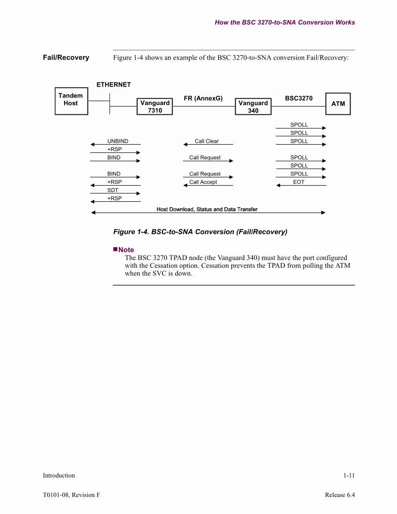
Fail/Recovery Figure 1-4 shows an example of the BSC 3270-to-SNA conversion Fail/Recovery:
Figure 1-4. BSC-to-SNA Conversion (Fail/Recovery)
NoteThe BSC 3270 TPAD node (the Vanguard 340) must have the port configured with the Cessation option. Cessation prevents the TPAD from polling the ATM when the SVC is down.
TandemHost Vanguard
7310Vanguard
340ATM
FR (AnnexG)
ETHERNET
BSC3270
UNBIND
+RSP
BIND
BIND
+RSP
SDT
Call Request
SPOLL
EOT
Call Clear
+RSP
SPOLL
SPOLL
SPOLL
SPOLLCall Request
Call Accept
Host Download, Status and Data TransferHost Download, Status and Data Transfer
SPOLL
(See Note #1)
Introduction 1-11
T0101-08, Revision F Release 6.4

SNA Sense Codes
SNA Sense Codes
Sense data refers to four bytes of hex data sent between SNA Conversion and the SNA host. Variations of sense data can be used in problem determination and diagnosis. Sense data can be included in a negative response, an UNBIND request, or an LUSTAT request. See Figure 1-5 Sense Data Format.
Figure 1-5. Sense Data Format
In the case of BSC 3270 or BSC 2780/3780 to SNA Conversion, a unique set of sense codes is mapped to unusual conditions occurring with the networks or the remote devices. These unique Sense Codes are presented to the host as an inbound UNBIND command.
NoteReference Appendix A of this manual for detailed Sense Code information.
Error Code and Alarms from Networks or Remote Devices
Reference Appendix A of this manual for detailed Error Code information from networks or remote devices through alarms or sense codes.
Category
BYTE 0 BYTE 1 BYTE 2 BYTE 3
Modifier Specific Information
Sense Code
Sense Data
Category Field
Modifier Field
‘00’ User Sense Data‘08’ Request Reject‘10’ Request Error‘20’ State Error‘40’ Request Header (RH) Usage Error‘80’ Path Error
‘00’ Reserved
Specific Information Field
‘XX, YY’ 2780/3780 Conditions3270
‘XX’
‘YY, ZZ’
1-12 Introduction

SNA Sense Codes
SNA-to-BSC Device Enable (ATM)
Follow These Steps...
Follow these steps to configure SNA-to-BSC 3270 Device Enable or Disable:
Device Enable Figure 1-6 shows an SNA-to-BSC 3270 Device Enable (ATM) example:
Figure 1-6. SNA-to-BSC 3270 Device Enable (ATM) Example
Step Action Result
1 Select Port/Station/Channel Control from the Control Terminal Port (CTP) Main menu.
The Port/Station/Channel Control menu Displays.
2 Select SNA Features Control from the Port/Station/Channel Control menu.
The SNA Features Control menu displays, with a prompt to select the feature to configure.
3 Select the feature to configure:• SNA to BSC
Device Enable• SNA to BSC
Device Disable
Your choice is displayed.
TandemHost Vanguard
7310Vanguard
340ATM
FR (AnnexG)
ETHERNET
BSC3270
Notify
+RSP
BIND
+RSP BIND
+RSP
SDT
ACTLU
+RSP
Call Request Poll ATM
EOTCall Accept
Introduction 1-13
T0101-08, Revision F Release 6.4

SNA Sense Codes
SNA-to-BSC 3270 Device Disable
Device Disable Figure 1-7 shows an SNA-to-BSC 3270 Device Disable example.
Figure 1-7. SNA-to-BSC 3270 Device Disable Example
Once disabled, the device unconditionally terminates the session. The system operator is responsible to ensure that an ATM customer is not in the middle of a bank transaction.
NoteThe Cessation Option (CESS+CESS3) must be enabled so that the TPAD does not send the poll to the ATM when the call is cleared.
Most Tandem Host systems continueto send a BIND command until theyget a response.
TandemHost Vanguard
7310Vanguard
340ATM
FR (AnnexG)
ETHERNET
BSC3270
UNBIND
BIND
Call Clear
Clear Accept
+RSP
BIND
See Note
Node
1-14 Introduction

SNA Sense Codes
Device Boot
Follow These Steps...
Device boot is needed for new parameters to take effect. Follow these steps to configure a Device Boot:
Device Boot The device unconditionally terminates to an LU session when booting. The system operator is responsible to ensure that an ATM customer is not in the middle of a bank transaction. Figure 1-8 shows a Device Boot example:
Figure 1-8. Device Boot Example
NoteThe Cessation Option (CESS+CESS3) must be enabled so that the TPAD does not send the poll to the ATM when the call is cleared.
When the TPAD is receiving a call, the TPAD cannot send a call accept until it receives an End Of Transmission (EOT) response to a general or specific poll.
Step Action Result
1 Select Boot from the Control Terminal Port (CTP) Main menu.
The Boot menu Displays.
2 Select SNA Features Records Boot from the Boot menu.
The SNA Features Record Boot menu displays, with a prompt for the selection.
3 Select the feature to configure:• SNA to BSC Conversion
Device
The feature displays.
TandemHost Vanguard
7310Vanguard
340ATM
FR (AnnexG)
ETHERNET
BSC3270
UNBIND
+RSP
BIND
+RSP
SDT
Call Request
Clear Accept
SPOLL
EOT
Call Clear
Call Accept
+RSP
See Note
Node
Introduction 1-15
T0101-08, Revision F Release 6.4

SNA Sense Codes
CautionWhen adding a new device, an LLC-SDLC station boot is required.
1-16 Introduction

SNA Sense Codes
LLC-SDLC Station Boot
LLC-SDLC Station Boot
An LLC-SDLC Station Boot is required for new LLC-SDLC station parameters to take effect. Modifying device Parameters; LU Name, link station name, and LU address require that the LLC-SDLC Station is booted.
Once booted, the device unconditionally terminates the session. The system operator is responsible to ensure that an ATM customer is not in the middle of a bank transaction.
NoteThe device unconditionally terminates to an LU session when booting an LLC-SDLC Station.
CautionA SLAC station boot is needed to make a new device active.
Introduction 1-17
T0101-08, Revision F Release 6.4

Chapter 2Configuration
Overview
Introduction This chapter provides configuration examples and procedures for BSC 3270-to-SNA conversion.
Configuration Information and Examples
Remote Site Configuration Information (TPAD)
When configuring the Remote Site (TPAD) you must configure the Port Options to CESS+CESS3 and configure the BSC/DSP3270 Device Table’s Device Control to SPEOT. Refer to “Remote Site Configuration (TPAD)” section on page 2-32 for parameter configurations.
Central Site Configuration Examples (HPAD)
The configuration examples show diagrams of possible network applications for the BSC 3270-to-SNA conversion. An SNA Tandem host is utilized in an Ethernet configuration. Figure 2-1 shows the HPAD placing a call. Figure 2-2 shows the TPAD placing a call.
Configuration 2-1

Configuration Information and Examples
Figure 2-1. Example of HPAD Placing A Call
Node RecordNode Name: HostNode Address: 100Node Number: 1
Node RecordNode Name: ATMNode Address: 200Node Number: 1
Port RecordPort Number: 101Port Type: ETHPort MAC Address:00-00-00-00-00Transmit Queue Limit: 50Bridge Link Number: 1Router Interface Number: 1Port Operating Mode: AUTO
LLC-SDLC StationEntry #1External MAC Address:00-00-00-00-00Internal SAP: 04External SAP: 04Link Station Type: SNABSCExternal PU Type: 4Ethernet Frame Type: EthernetInitiate TEST Frame: ONLLC Profile Name: DefaultXID Value: 02000170FFF
SNA-BSC
DSP
X.25orFR Frame Relay
WAN
or X.25
Vanguard TPAD Node
Vanguard 7300
BisyncX.25orFR
Vanguard HPAD NodeATM
BisyncTandemSNA
Host
SNA to BSC 3270 Conversion Device TableLU Name: BSCLU001LU ADDR: 2Link Station Name: LSC-ETH1Calling Address: Destination Control Unit Address: 40Destination Device Address: 40Destination Device Type: ATM3270 Command/WCC inserted in outbound RU: F1C2Autocall Mnemonic: ATM
Route Selection TableEntry Number: 1Address: 200#1 Destination: FRI-202S1
Mnemonic TableEntry #: 1Mnemonic Name: ATMCall Parameters: 20002
FRI Port RecordPort Number: 202Port Type: FRIConnection Type: SIMPClock Source: INTClock Speed: 6400Highest Station Number: 1FRI Station RecordPort Number: 1Station Number: 1Station Type: Annex_GDLCI: 16CIR: 16000BC: 16000End to End Transit Delay: 50Congestion Mode: NormalLink Address: DCE
Node 100 Node 200
101 202
Bisync Port RecordPort Number: 2Port Type: BSC3270PAD Type: TPADClock Source: INTClock Speed: 9600Number of Devices: 1Character Set: EBCDICPort Options: CESS+CESS3
Port 1 Port 2
Vanguard 340
Route Selection TableEntry Number: 1Address: 100#1 Destination: FRI-201S1
FRI Port RecordPort Number: 1Port Type: FRConnection Type: SIMPClock Source: EXTClock Speed: 6400Highest Station Number: 1FRI Station RecordPort Number: 1Station Number: 1Station Type: Annex_GDLCI: 16CIR: 16000BC: 16000End to End Transit Delay: 50Congestion Mode: NormalLink Address: DTE
BSC/DSP3270 Device TableConfigurationBSC Control Unit Address: 40BSC Device Address: 40DSP Device Type: TERMDSP Control: NONEDevice Control: SPOLL+NSERVDevice Option: NONEDSP Device Characteristics: NONEDSP Device Format Size: 480DSP Character Set Capability: NONEDSP Application Identifier: 0Connection Request Mode: 2
LLC2
2-2 Configuration

Configuration Information and Examples
Figure 2-2. Example of TPAD Placing A Call
Node RecordNode Name: HostNode Address: 100Node Number: 1
Node RecordNode Name: ATMNode Address: 200Node Number: 1
Port RecordPort Number: 101Port Type: ETHPort MAC Address:00-00-00-00-00Transmit Queue Limit: 50Bridge Link Number: 1Router Interface Number: 1Port Operating Mode: AUTO
LLC-SDLC StationEntry #1External MAC Address:00-00-00-00-00Internal SAP: 04External SAP: 04Link Station Type: SNABSCExternal PU Type: 4Ethernet Frame Type: EthernetInitiate TEST Frame: ONLLC Profile Name: DefaultXID Value: 02000170FFF
SNA-BSC
DSP
X.25orFR Frame Relay
WAN
or X.25
Vanguard TPAD Node
Vanguard 7300
BisyncX.25orFR
Vanguard HPAD NodeATM
BisyncTandemSNA
Host
SNA to BSC 3270 Conversion Device TableLU Name: BSCLU001LU ADDR: 2Link Station Name: LSC-ETH1Calling Address: 20002Destination Control Unit Address: 40Destination Device Address: 40Destination Device Type: ATM3270 Command/WCC inserted in outbound RU: F1C2Connect Request Mode: 2
Route Selection TableEntry Number: 1Address: 200#1 Destination: FRI-202S1Entry Number: 2Address: 100101*#1 Destination: SNABSC
Mnemonic TableEntry #: 1Mnemonic Name: HostCall Parameters: 10010101
FRI Port RecordPort Number: 202Port Type: FRIConnection Type: SIMPClock Source: INTClock Speed: 6400Highest Station Number: 1FRI Station RecordPort Number: 1Station Number: 1Station Type: Annex_GDLCI: 16CIR: 16000BC: 16000End to End Transit Delay: 50Congestion Mode: NormalLink Address: DCE
Node 100 Node 200
101 202
Bisync Port RecordPort Number: 2Port Type: BSC3270PAD Type: TPADClock Source: INTClock Speed: 9600Number of Devices: 1Character Set: EBCDIC
Port 1 Port 2
Vanguard 340
Route Selection TableEntry Number: 1Address: 100#1 Destination: FRI-1S1
FRI Port RecordPort Number: 1Port Type: FRConnection Type: SIMPClock Source: EXTClock Speed: 6400Highest Station Number: 1FRI Station RecordPort Number: 1Station Number: 1Station Type: Annex_GDLCI: 16CIR: 16000BC: 16000End to End Transit Delay: 50Congestion Mode: NormalLink Address: DTE
LLC2
BSC/DSP3270 Device TableConfigurationBSC Control Unit Address: 40BSC Device Address: 40DSP Device Type: TERMDSP Control: ORG+AUTODevice Control: SPOLL+NSERVDevice Option: NONEDSP Device Characteristics: NONEDSP Device Format Size: 480DSP Character Set Capability: NONEDSP Application Identifier: 0Connection Request Mode: 2Autocall Mnemonic: Host
Configuration 2-3
T0101-08, Revision F Release 6.4

Configuration Information and Examples
Before You Start
Online Help Entering a ? displays online Help for the current parameter option on the screen.
Ease of Configuration
With Ease of Configuration enabled, you only need to boot the port to make changes to the parameters marked with an asterisk.
For more information on Ease of Configuration, refer to the introductory portion of the SNA Feature Protocols Manual, (Part Number T0101).
Parameters with an asterisk (*)
Parameters identified by an asterisk require a node boot for changes to the parameter to take effect.
2-4 Configuration

Vanguard 6455 Requirements for Bisync
Vanguard 6455 Requirements for Bisync
Vanguard 6455 Requirements for BSC 3270-to-SNA Conversion
The guidelines below are required when using the BSC 3270-to-SNA feature:
• 32 Meg SIMM Memory Module• Local Dynamic Port Creation Heap Size needs
to be configured Bisync and AS/400
NoteWhen setting the Local Dynamic Port Creation Heap Size, refer to the Ease of Configuration information located in the About The Vanguard Applications Ware SNA Feature Protocols Manual section of the SNA Feature Protocols Binder (Part Number T0101). A copy of your current configuration files should be saved before changing the Local Dynamic Port Create Heap Size.
Increase Parameters to Maximum Value
The following Node Record Parameters need to be increased in order to accommodate increasing the number of SNA to Bisync 3270 Devices to 256:
• Mnemonic Table Size• Quantity of DSP Devices• Maximum Simultaneous Calls
The Frame Relay Station or X.25 Port parameter; Number of Two Way Simultaneous Calls, needs to be increased in order to accommodate increasing the number of SNA to Bisync 3270 Devices to 256.
Configuration 2-5
T0101-08, Revision F Release 6.4
Configuring a Node
Configuring a Node
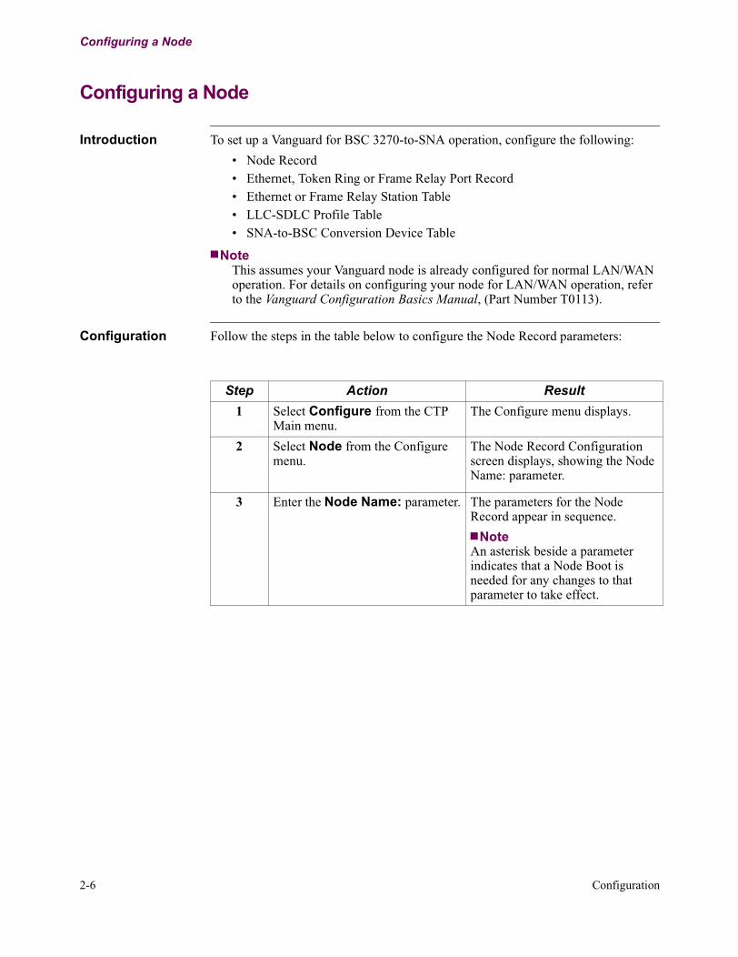
Introduction To set up a Vanguard for BSC 3270-to-SNA operation, configure the following:
• Node Record• Ethernet, Token Ring or Frame Relay Port Record• Ethernet or Frame Relay Station Table• LLC-SDLC Profile Table• SNA-to-BSC Conversion Device Table
NoteThis assumes your Vanguard node is already configured for normal LAN/WAN operation. For details on configuring your node for LAN/WAN operation, refer to the Vanguard Configuration Basics Manual, (Part Number T0113).
Configuration Follow the steps in the table below to configure the Node Record parameters:
Step Action Result
1 Select Configure from the CTP Main menu.
The Configure menu displays.
2 Select Node from the Configure menu.
The Node Record Configuration screen displays, showing the Node Name: parameter.
3 Enter the Node Name: parameter. The parameters for the Node Record appear in sequence.
NoteAn asterisk beside a parameter indicates that a Node Boot is needed for any changes to that parameter to take effect.
2-6 Configuration

Configuring a Node
Configure Menu Figure 2-3 is a sample Configure Menu for Central Site (HPAD):
Figure 2-3. Configure Menu Example
Node: Address: Date: Time:Menu: Configure Path: (Main.6)
1. Node 19. PPP Profiles2. Port 20. ToW Table3. Configure Network Services 21. AT Dialer Profile4. Inbound Call Translation Table 22. SoTCP5. Outbound Call Translation Table 23. SNA Features Configure6. Calling Addr Translation Table 24. (reserved)7. CUD based Addr Translation Table 25. (reserved)8. SDLC Port Stations 26. (reserved)9. NUI/Password Table 27. (reserved)10. FRI Stations 28. (reserved)11. Configure Bridge 29. (reserved)12. Configure LAN Connections 30. Configure SNMP13. Software Key Table14. Congifure Router15. LLC to SDLC Tables16. DORA Record17. TCP18. PPP
-Enter Selection:
Configuration 2-7
T0101-08, Revision F Release 6.4

Configuring Port Records
Configuring Port Records
Introduction Port Records store the port configuration parameters, with each active port having a separate record. Active port number (location) and port type must be defined before you configure the remaining Port Record parameters.
Configuration Follow these steps to configure the Port Records:
Step Action Result
1 Select Configure from the CTP Main menu.
The Configure menu displays.
2 Select Port from the Configure menu.
The Port Number parameter displays.
3 At the prompt, enter the number of the port you want to configure and press Return.
The parameters are successively displayed.
NoteWhen an asterisk appears beside a parameter in a record, a Node Boot is needed for any changes to that parameter to take effect.
2-8 Configuration

Configuring Port Records
Configuring the Ethernet Port Record
Ethernet Port Record Parameters
The Ethernet Port record contains these parameters:
Port Number
Range: 101 to 599, 2000 to 3999
Default: 101
Description: Enter the number of the port to configure. This number is the Port Record reference number and represents both physical and virtual ports. Physical ports are located at the front and rear of the hardware chassis.
*Port Type
Range: NULL, ETH
Default: ETH
Description: Specify the type of port you are configuring:• NULL - NULL port type• ETH - Ethernet port type
NoteA change to this parameter requires a node boot to take effect.
*Port MAC Address
Range: 00-00-00-00-00-00 to FE-FF-FF-FF-FF-FF
Default: 00-00-00-00-00-00
Description: Specifies the MAC address of the LAN port. The entered value of 00-00-00-00-00-00 is replaced by the Burned in Address (BIA) if the LAN hardware is present.
NoteA change to this parameter requires a node boot to take effect.
Transmit Queue Limit
Range: 20 to 500
Default: 50
Description: Specifies the maximum number of frames that can be queued on the LAN transmitter before any frames are dropped.
Configuration 2-9
T0101-08, Revision F Release 6.4

Configuring Port Records
*Bridge Link Number
Range: 1 to 5
Default: 1
Description: Specifies the bridge link number associated with the LAN port. The corresponding bridge link record must be configured under the bridge configuration menu.
*Router Interface Number
Range: 1 to 50
Default: 1
Description: Specifies the router interface number associated with this LAN port.
Port Operating Mode
Range: AUTO, 1000FD, 100FD, 100HD, 10FD, 10HD
Default: AUTO
Description: Specifies whether this LAN port runs in 1000Mbit Full-Duplex, 100Mbit Full-Duplex, 100Mbit Half-Duplex, 10Mbit Full-Duplex, 10Mbit Half-Duplex, or Auto-Negotiation mode.
NoteVanguard 7300 Series - Release 6.4 and greater software supports 1000FD on ports 101 and 103 using the IBM750FX CPU card. ETH1 is port 101, ETH2 is port 103. Port 102 is the COM port.
2-10 Configuration

Configuring Station Records
Configuring Station Records
Introduction Station records store the station configuration parameters, with each station assigned a separate record. The ports must be defined before you can configure the station record parameters.
Station records are configured through the various sets of LLC-to-SDLC Station Table parameters. The four types of station tables are:
• LLC Profile Table• Frame Relay Station Table• Ethernet Station Table• Token Ring
LLC-to-SDLC Table Menu
Figure 2-4 shows the LLC-to-SDLC Tables Menu:
Figure 2-4. LLC to SDLC Tables Menu
1. LLC Profile Table
2. Frame Relay Station Table
3. Ethernet Station Table
4. Token Ring
Node: nodename Address: (blank) Date: 12-JAN-01 Time: 7:19:29
Menu: Configure Path:
LLC to SDLC Tables
Configuration 2-11
T0101-08, Revision F Release 6.4

Configuring Station Records
Configuring the LLC-to-SDLC Tables
The LLC-to-SDLC Tables must be configured for each active station and conversion type. Follow these steps to access the tables:
Step Action Result
1 Select Configure from the CTP Main menu.
The Configure menu displays.
2 Select LLC to SDLC Tables from the Configure menu.
The LLC to SDLC Tables menu displays, with a prompt for the selection.
3 Select the station type to configure:• LLC Profile Table• Frame Relay Station Table• Ethernet Station Table• Token Ring
The corresponding Station Table Configuration displays, with the prompt for the entry number.
NoteThe station type is listed only if the interface card is inserted and the port is configured.
4 Select the first entry number. The prompt for the first station parameter displays. As you enter each parameter, the next parameter choice is displayed.
2-12 Configuration

Configuring Station Records
Ethernet Station Table Parameters
Parameter Numbers
The LLC-SDLC Conversion Ethernet Station Configuration contains these parameters:
Entry Number
Range: 1 to 1000
Default: 1
Description: Entry number used to refer to this table record.
External MAC Address
Range: 00-00-00-00-00-00 to FF-FF-FF-FF-FF-FF (hexadecimal digits)
Default: 00-00-00-00-00-00
Description: The MAC Address of the External LAN device associated with this station. For MAC Address Auto-Learn, enter 00-00-00-00-00-00.
NoteThere are two forms commonly used for displaying the address: Canonical and non-Canonical.
*Internal MAC Address
Range: 00-00-00-00-00-00 to FF-FF-FF-FF-FF-FF (hexadecimal digits)
Default: 10-00-7C-54-29-77
Description: The default internal MAC address is the MAC address of the LAN port. If this default internal MAC address is not to be used for this station, the configured Internal MAC address should be of the following form:nn:nn:nn:nn:ss:ss1) nn:nn:nn:nn must be the same for all stations associated with this LAN port and not using the default MAC Address. nn:nn:nn:nn must also be unique to this node, and must not be zero’s.2) ss:ss must be different for each station associated with this LAN port and does not use the default MAC address, unless Service Access Point (SAP) multiplexing is being used to uniquely differentiate the stations.
NoteA change to this parameter requires a node boot to take effect.
Configuration 2-13
T0101-08, Revision F Release 6.4

Configuring Station Records
Internal SAP
Range: 01-FE (hexadecimal digits)
Default: 04
Description: The local Service Access Point (SAP) of this station. This should be 04, or a multiple of 04.
External SAP
Range: 01-FE (hexadecimal digits)
Default: 04
Description: The Service Access Point (SAP) for the device associated with this station. This should be 04, or a multiple of 04.
*Link Station Type
Range: SLAC, 5494, SNABSC
Default: SLAC
Description: • SLAC - LLC-SDLC Conversion (via QLLC)• 5494 - APPN LEN Link Station for support of 5394 type
downstream controllers• SNABSC - SNA PU type 2.0 Link Station for support of SNA
to Bisync Conversion
NoteYou must perform a node boot for changes to 5494 to take effect.
External PU Type
Range: 2, 2.1, 4
Default: 4
Description: The Physical Unit (PU) Type of the device associated with this station. For MAC Address Autolearn, use Type 2 and 2.1 only.
Ethernet Frame Type
Range: 802.3, Ethernet
Default: 802.3
Description: This indicates whether 802.3 or Ethernet Version 2 frame format is to be transmitted onto the Ethernet for this station.
2-14 Configuration

Configuring Station Records
Initiate TEST Frame
Range: OFF, ON
Default: ON
Description: Controls whether TEST poll frames are initiated locally during link setup.
• OFF - The other side should initiate TEST frames • ON - This side generates TEST poll frames
LLC Profile Name
Range: 0 to 8 (alphanumeric characters)
Default: DEFAULT
Description: The name of the LLC-SDLC Conversion Profile Table entry that provides the LLC operating parameters for this station. To blank this field press the space bar.
XID Value
Range: 0 to 14 (hexadecimal digits)
Default: (blank)
Description: This is the identification sent by an HPAD station when External Physical Unit (PU) Type is set to 4, or by a TPAD station in the form of a QXID response when External PU Type is set to 2. To blank this field press the space bar.
Configuration 2-15
T0101-08, Revision F Release 6.4

Configuring Station Records
LLC Options
Range: NONE, NOCALLXID, 1490APPC, SAVELEARNED, BACKUP
Default: NONE
Description: Select LLC options on this stations follows:• NONE - No special LLC station option (recommended for
Link Station Type = SNABSC).• NOCALLXID - an XID is not sent from this LLC station to
the external PU upon the LLC Station call establishment.• 1490APPC - Enables the Frame Relay LLC station to send the
APPC NLPID when configured as a Type 2.1 External PU Type.
• SAVELEARNED - Save the learned External MAC Address into the CMEM record for this LAN-attached LLC Station. Only applies if the external MAC Address is set to 00-00-00-00-00-00.
• BACKUP - Used for two identical stations on one LAN. This station becomes active when a call is placed to it. Must be used with the WAIT initiate test frame option.
NoteWhere applicable, the options can be combined. Example: NOCALLXID+SAVELEARNED.
2-16 Configuration

Configuring Station Records
Frame Relay Station Table Parameters
Parameters The Frame Relay LLC-SDLC station records are used when attaching to a host or front-end processor (when Ethernet is not used). The LLC-SDLC Conversion Frame Relay Station table contains these following parameters:
Entry Number
Range: 1 to 1000
Default: 1
Description: Entry number used to refer to this table record.
*Frame Relay Port Number
Range: 1 to 3699
Default: 201
Description: The port number of the Frame Relay port that the LLC-SDLC Conversion station is connected to.
NoteYou must perform a node boot for changes to this parameter to take effect.
*Frame Relay Station Number
Range: 1 to 254
Default: 1
Description: The Frame Relay station number on the Frame Relay port to which this LLC-SDLC Conversion station is connected. To obtain the corresponding DLCI number, refer to the configuration for that Frame Relay Station.
NoteYou must perform a node boot for changes to this parameter to take effect.
Configuration 2-17
T0101-08, Revision F Release 6.4

Configuring Station Records
1490 Encapsulation
Range: LLC, BAN
Default: LLC
Description: Frame Relay 1490 frame format used to encapsulate LLC frames sent and received by this station.
• LLC - LLC Frame is encapsulated in 1490 with the NLPID for 802.2.
• BAN - LLC Frame is encapsulated in 1490 with the BAN and BNI MACs, and the NLPID for 802.5.
Internal SAP
Range: 01-FE (hexadecimal digits)
Default: 04
Description: The local Service Access Point (SAP) of this station. This should be 04, or a multiple of 04.
External SAP
Range: 01-FE (hexadecimal digits)
Default: 04
Description: The Service Access Point (SAP) at the device associated with this station. This should be 04, or a multiple of 04.
*Link Station Type
Range: SLAC, 5494, SNABSC
Default: SLAC
Description: • SLAC - LLC-SDLC Conversion (through QLLC)• 5494 - APPN LEN link station for support of 5394-type
downstream controllers.• SNABSC - SNA PU type 2.0 link station for support of
SNA-to-Bisync Conversion.
NoteYou must perform a node boot for changes to 5494 to take effect
2-18 Configuration

Configuring Station Records
External PU Type
Range: 2, 2.1, 4
Default: 4
Description: The Physical Unit (PU) Type of the device associated with this station. For MAC Address Autolearn use Type 2 and 2.1, only.
Initiate Test Frame
Range: ON, OFF
Default: ON
Description: Controls whether TEST poll frames are initiated locally during link setup.
• ON - This side generates TEST poll frames.• OFF - The other side should initiate TEST frames. This is the
only mode supported for MAC Address Autolearn.
Configuration 2-19
T0101-08, Revision F Release 6.4

Configuring Station Records
LLC Profile Table
Introduction The LLC Profile Table is used to provide information about the stations attached to an SDLC Port.
LLC Profile Table Figure 2-5 shows the LLC to SDLC Tables Menu and the LLC Profile Table selection.
Figure 2-5. LLC Profile Table
Parameters The LLC Profile Table configuration contains these parameters:
1. LLC Profile Table
2. Frame Relay Station Table
3. Ethernet Station Table
4. Token Ring
Node: nodename Address: (blank) Date: 12-JAN-01 Time: 7:19:29
Menu: Configure Path:
LLC to SDLC Tables
Entry Number
Range: 1 to 8
Default: 1
Description: Entry number used to refer to this table record.
Profile Name
Range: 0 to 8 (alphanumeric characters)
Default: DEFAULT
Description: The name of this profile entry, referenced by LLC-SDLC conversion stations for their LLC operating parameters. To blank this field press the space bar.
2-20 Configuration

Configuring Station Records
T1 Reply Timer
Range: 1 to 25 seconds
Default: 3
Description: This Ack Timer is used by a station to detect the remote station’s failure to acknowledge an outstanding I-frame or supervisory frame with poll bit set to one.
T2 RX Ack Timer
Range: 1 to 255 tenths of seconds
Default: 3
Description: The Receive Ack Timer is used by a station to determine how long it withholds acknowledgment of a frame(s) from the remote station that requires acknowledgment. This method reduces the number of acknowledgements generated by a link station. When this timer expires, the link station should immediately send an acknowledgment for all received frames not yet acknowledged.
NoteTime is in tenths of seconds.
T1 Inactivity Timer
Range: 2 to 255 seconds
Default: 30
Description: The Idle Timer is used by a station to detect an inoperative condition of the logical link. This timer is started when the link becomes idle (no data to pass and no outstanding acknowledgments) and if the timer expires, the station sends a supervisory frame with the poll bit set to one.
N2 Retry Count
Range: 1 to 20
Default: 8
Description: This count defines the number of times an I-frame or supervisory frame with poll bit set to one is transmitted, due to T1 acknowledgment time-out, before the logical link is declared down (inoperative).
Configuration 2-21
T0101-08, Revision F Release 6.4

Configuring Station Records
N3 Ack Delay Count
Range: 1 to 15
Default: 3
Description: The receive count is used in conjunction with T2 to reduce the number of acknowledgments a station generates. The receive count is used by a station to determine how many frames are received from the remote station while withholding acknowledgment of these frames. This method reduces the number of acknowledgements generated by a link station. When this count expires, the link station should immediately send an acknowledgment for all received frames not yet acknowledged.
TX Window Size
Range: 1 to 15
Default: 7
Description: The transmit window size parameter defines the maximum number of I-frames a station can transmit without acknowledgment.
TA Startup Timer
Range: 1 to 255 seconds
Default: 10
Description: The TA Startup Timer is used by a station as the retry timer when establishing a logical link.
SLAC Ring Number
Range: 0000-0FFF (hexadecimal digits)
Default: 0000
Description: This is the hexadecimal ring number used by Frame Relay 1490 SLAC stations using 802.5 (BAN) encapsulation. If a value of 0 (zero, the default) is entered, this ring number is not inserted into the Route Indicator field.
2-22 Configuration
Configuring Station Records
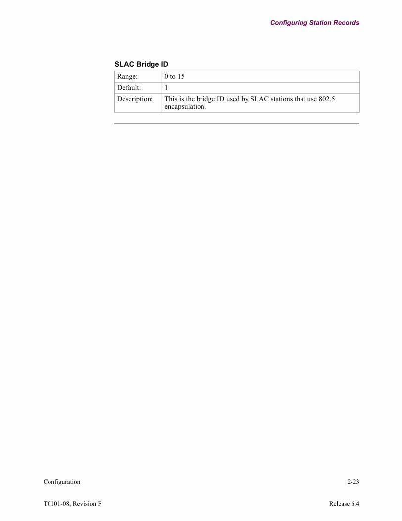
SLAC Bridge ID
Range: 0 to 15
Default: 1
Description: This is the bridge ID used by SLAC stations that use 802.5 encapsulation.
Configuration 2-23
T0101-08, Revision F Release 6.4

SNA Features Configure Tables
SNA Features Configure Tables
Follow These Steps...
Follow these steps to configure the SNA Features Table record:
SNA Features Configure Menu
Figure 2-6 shows the SNA Features Configure Menu.
Figure 2-6. SNA Features Configure
Step Action Result
1 Select Configure from the Control Terminal Port (CTP) Main menu.
The Configure Menu Displays.
2 Select SNA Features Configure from the Configure menu.
The SNA Features Configure menu displays, with a prompt for the selection.
3 Select the feature to configure:• APPN Node Table• SNA to BSC Conversion
Device Table
At the prompt, enter the number of the feature you are configuring.
1. APPN Node Table
2. SNA to BSC Conversion Device Table
Node: nodename Address: (blank) Date: 12-JAN-01 Time: 7:19:29
Menu: Configure Path:
SNA Features Configure
2-24 Configuration

SNA Features Configure Tables
Advanced Peer-to-Peer Networking (APPN) Node Table
Default Setting For BSC 3270-to-SNA conversion use the default setting for the APPN Node Table parameter.
SNA to BSC Conversion Device Tables (3270)
*APPN Node Table
Range: 0 to 8 (alphanumeric characters)
Default: APPN
Description: The Local Network Identifier associated with this Vanguard.
NoteThe Adjacent AS/400 must have this Network Identifier defined in its Network Attributes or defined in its definition of the APPC and RWS Controller used to attach to this Vanguard. To blank this field press the space bar.
Entry Number
Range: 1 to 256 or 1 to 2000
Default: 1
Description: Entry number used to refer to this table record.
NoteMaximum range for the Vanguard 6455 is 256.Maximum range for the Vanguard 7300 Series is 2,000.
LU Name
Range: 1 to 8 (alphanumeric characters)
Default: (blank)
Description: This is the name of the Logical Unit (LU). To blank this field press the space bar.
NoteYou must perform a node boot for changes to this parameter to take effect.
Configuration 2-25
T0101-08, Revision F Release 6.4

SNA Features Configure Tables
LU ADDR
Range: 1 to 255
Default: 1
Description: This is the Logical Unit (LU) identification number.
Link Station Name:
Range: 1 to 16 (alphanumeric characters)
Default: LSC-ETH1
Description: This is the name of the SNA Station that the specific Logical Unit (LU) or the LU group is being defined for. To blank this field press the space bar.
Calling Address
Range: 0 to 15 (decimal digits)
Default: (blank)
Description: Calls placed from this node have this address in the X.25 calling address. For calls received by this node, this field is compared to the X.25 calling address and a match must be made in order for the call to accepted. To blank this field press the space bar.
Destination Control Unit Address
Range: 00-D9 (hexadecimal digits)
Default: 40
Description: Specifies control unit address on remote PAD. Used with Connection Request Mode = 2 or 3. The address consists of two hexadecimal digits. Valid ranges depend on the device.Character Set as follows:
• EBCDIC: 40, C1, C2, C3, C4, C5, C6, C7, C8, C9, 4A, 4B, 4C, 4D, 4E, 4F, 50, D1, D2, D3, D4, D5, D6, D7, D8, D9, 5A, 5B, 5C, 5D, 5E, 5F
• ASCII: 20, 41, 42, 43, 44, 45, 46, 47, 48, 49, 5B, 2E, 3C, 28, 2B, 21, 26, 4A, 4B, 4C, 4D, 4E, 4F, 50, 51, 52, 5D, 24, 2A, 29, 3B, 5E
2-26 Configuration
SNA Features Configure Tables
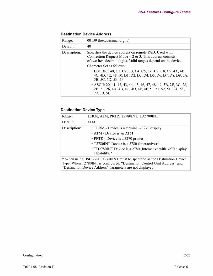
Destination Device Address
Range: 00-D9 (hexadecimal digits)
Default: 40
Description: Specifies the device address on remote PAD. Used with Connection Request Mode = 2 or 3. This address consists of two hexadecimal digits. Valid ranges depend on the device.Character Set as follows:
• EBCDIC: 40, C1, C2, C3, C4, C5, C6, C7, C8, C9, 4A, 4B, 4C, 4D, 4E, 4F, 50, D1, D2, D3, D4, D5, D6, D7, D8, D9, 5A, 5B, 5C, 5D, 5E, 5F
• ASCII: 20, 41, 42, 43, 44, 45, 46, 47, 48, 49, 5B, 2E, 3C, 28, 2B, 21, 26, 4A, 4B, 4C, 4D, 4E, 4F, 50, 51, 52, 5D, 24, 2A, 29, 3B, 5E
Destination Device Type
Range: TERM, ATM, PRTR, T2780INT, TD2780INT
Default: ATM
Description: • TERM - Device is a terminal - 3270 display• ATM - Device is an ATM• PRTR - Device is a 3270 printer• T2780INT Device is a 2780 (Interactive)*• TD2780INT Device is a 2780 (Interactive with 3270 display
capability)*
* When using BSC 2780, T2780INT must be specified as the Destination Device Type. When T2780INT is configured, “Destination Control Unit Address” and “Destination Device Address” parameters are not displayed.
Configuration 2-27
T0101-08, Revision F Release 6.4
SNA Features Configure Tables
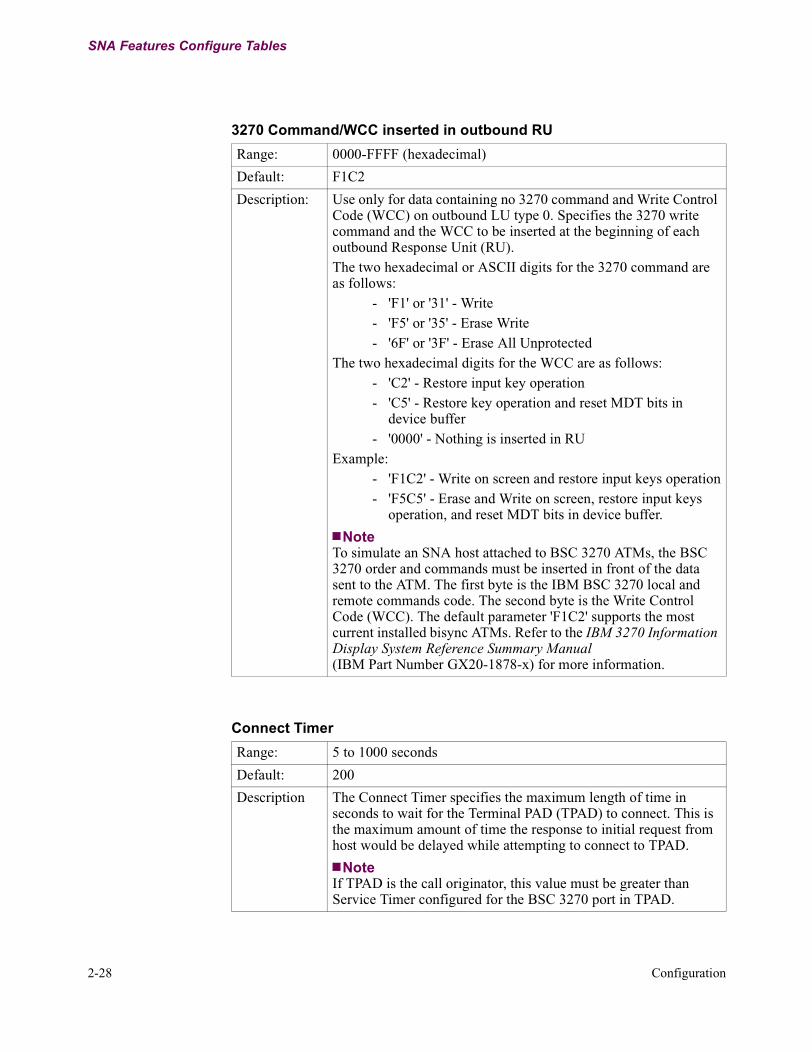
3270 Command/WCC inserted in outbound RU
Range: 0000-FFFF (hexadecimal)
Default: F1C2
Description: Use only for data containing no 3270 command and Write Control Code (WCC) on outbound LU type 0. Specifies the 3270 write command and the WCC to be inserted at the beginning of each outbound Response Unit (RU).The two hexadecimal or ASCII digits for the 3270 command are as follows:
- 'F1' or '31' - Write- 'F5' or '35' - Erase Write- '6F' or '3F' - Erase All Unprotected
The two hexadecimal digits for the WCC are as follows:- 'C2' - Restore input key operation- 'C5' - Restore key operation and reset MDT bits in
device buffer- '0000' - Nothing is inserted in RU
Example:- 'F1C2' - Write on screen and restore input keys operation- 'F5C5' - Erase and Write on screen, restore input keys
operation, and reset MDT bits in device buffer.
NoteTo simulate an SNA host attached to BSC 3270 ATMs, the BSC 3270 order and commands must be inserted in front of the data sent to the ATM. The first byte is the IBM BSC 3270 local and remote commands code. The second byte is the Write Control Code (WCC). The default parameter 'F1C2' supports the most current installed bisync ATMs. Refer to the IBM 3270 Information Display System Reference Summary Manual (IBM Part Number GX20-1878-x) for more information.
Connect Timer
Range: 5 to 1000 seconds
Default: 200
Description The Connect Timer specifies the maximum length of time in seconds to wait for the Terminal PAD (TPAD) to connect. This is the maximum amount of time the response to initial request from host would be delayed while attempting to connect to TPAD.
NoteIf TPAD is the call originator, this value must be greater than Service Timer configured for the BSC 3270 port in TPAD.
2-28 Configuration

SNA Features Configure Tables
SNA Options
Range: NONE, UBNSHC, BINDCR, RENOTIFY, LUADBG, DSPDBG, SESDBG
Default: NONE
Description: • NONE - No User’s SNA Option• UBNSHC - Send UNBIND to PLU after SHUTC• BINDCR - When configured, Call Request is always sent
when Bind is received.• RENOTIFY -When configured, sends Notify down or up to
initiate re-logon after a device disconnection or reconnection.• LUADBG - Print LUA Debug Information• DSPDBG - Print DSP Debug Information• SESDBG - Print SES Debug Information
DSP Device Characteristics
Range: NONE, XPAR, COLOR, PRINa
Default: NONE
Description: • NONE - No Options• XPAR - Device supports transparency• COLOR - Device supports color• PRINa - Printer is attached to a terminal device
NoteAny combination of the above can be specified by summing. Example: COLOR+PRINa
Character Set
Range: ASCII, EBCDIC
Default: EBCDIC
Description: Indicates whether Terminal/ATM devices on this port support an ASCII or EBCDIC character set.
DSP Device Format Size
Range: 480, 960, 1920, 2560, 3440, 3564
Default: 480
Description: Specifies the maximum size of the terminal or printer message.
Configuration 2-29
T0101-08, Revision F Release 6.4

SNA Features Configure Tables
DSP Character Set Capability
Range: NONE, APL, TEXT
Default: NONE
Description: Indicates device capability:• NONE - no indication of capability• APL - APL capability• TEXT - Text capability
NoteAny combination of the above can be specified by summing. Example: APL+TEXT
DSP Application Identifier
Range: 0 to 255
Default: 0
Description: Specifies the target application to which this device would be connected. This should match with the application ID of the Host DSP device.
Connection Request Mode
Range: 2 to 3
Default: 2
Description: Specifies which Display System Protocol (DSP) Connection Request Mode (CRM) to use. There are two modes of connection as follows:
• 2 - Specific class CRM-connects to a specific device as indicated in the destination control unit and device address.
• 3 - Non-specific class CRM-connects to any device as indicated in the destination control unit address.
Autocall Mnemonic
Range: 0 to 8 (alphanumeric characters)
Default: (blank)
Description: This mnemonic references the remote X.25 address which is autocalled. If blank, then autocalling is disabled and the other end should initiate the call. To blank this field press the space bar.
2-30 Configuration

SNA Features Configure Tables
DSP Compatibility
Range: YES, NO
Default: NO
Description: Select YES if the device connects to a DSP host or if the device connects to a 6507/6525 node with 2.13 or higher software revision. Select NO if the device connects to 6507/6525 with pre-2.13 release software.
Billing Records
Range: OFF, ON
Default: OFF
Description: This controls whether billing (accounting) records are created for calls on this station.
• OFF: No billing records are created• ON: Billing records are created
Configuration 2-31
T0101-08, Revision F Release 6.4

Remote Site Configuration (TPAD)
Remote Site Configuration (TPAD)
Remote Site Configuration Port Options
To configure the Remote Site (TPAD) CESS+CESS3 must be selected. Figure 2-7 shows the parameters in the Configuration record.
Configure->Port->Port Options: CESS+CESS3
Figure 2-7. Configure Port Options
Port Number
*Port Type
PAD Type
Clock Source
Clock Speed
Contention
*Number of Devices
Service Timer
Error Threshold Count
Response Timeout
Host PAD Timeout
Inter Buffer Timeout
Idle Device Timeout
Printer Disconnect Timer
SIGNON Key
DISC Key
Character set
Port Subaddress
Port OptionsRestricted Connection Destination
Next Select Timer
Poll Frequency Period
Poll List Timer
Node: nodename Address: (blank) Date: 12-JUN-97 Time: 7:19:29
Menu: Configure Path:
Port
2-32 Configuration
Remote Site Configuration (TPAD)
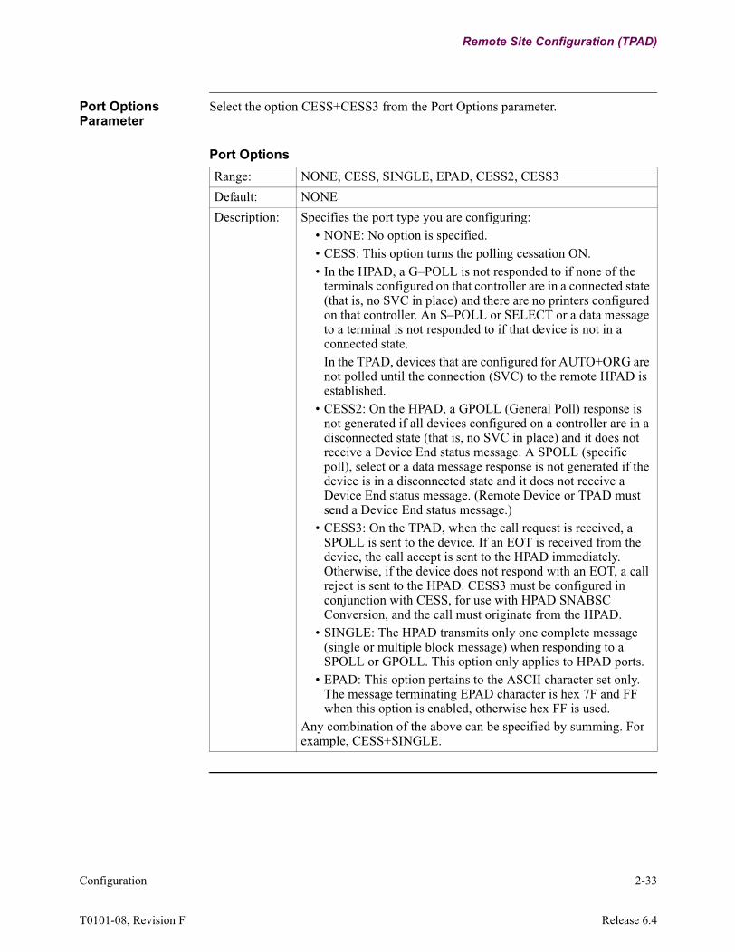
Port Options Parameter
Select the option CESS+CESS3 from the Port Options parameter.
Port Options
Range: NONE, CESS, SINGLE, EPAD, CESS2, CESS3
Default: NONE
Description: Specifies the port type you are configuring:• NONE: No option is specified.• CESS: This option turns the polling cessation ON.• In the HPAD, a G–POLL is not responded to if none of the
terminals configured on that controller are in a connected state (that is, no SVC in place) and there are no printers configured on that controller. An S–POLL or SELECT or a data message to a terminal is not responded to if that device is not in a connected state. In the TPAD, devices that are configured for AUTO+ORG are not polled until the connection (SVC) to the remote HPAD is established.
• CESS2: On the HPAD, a GPOLL (General Poll) response is not generated if all devices configured on a controller are in a disconnected state (that is, no SVC in place) and it does not receive a Device End status message. A SPOLL (specific poll), select or a data message response is not generated if the device is in a disconnected state and it does not receive a Device End status message. (Remote Device or TPAD must send a Device End status message.)
• CESS3: On the TPAD, when the call request is received, a SPOLL is sent to the device. If an EOT is received from the device, the call accept is sent to the HPAD immediately. Otherwise, if the device does not respond with an EOT, a call reject is sent to the HPAD. CESS3 must be configured in conjunction with CESS, for use with HPAD SNABSC Conversion, and the call must originate from the HPAD.
• SINGLE: The HPAD transmits only one complete message (single or multiple block message) when responding to a SPOLL or GPOLL. This option only applies to HPAD ports.
• EPAD: This option pertains to the ASCII character set only. The message terminating EPAD character is hex 7F and FF when this option is enabled, otherwise hex FF is used.
Any combination of the above can be specified by summing. For example, CESS+SINGLE.
Configuration 2-33
T0101-08, Revision F Release 6.4

Remote Site Configuration (TPAD)
Remote Site Configuration BSC/DSP3270 Device Table
Figure 2-8 is a sample Remote Site (TPAD) Configure Menu. SPEOT must be selected in the Device Control parameter.
Configure->BSC/DSP3270 Device Table->Device Control: SPEOT
Figure 2-8. Configure Menu Example
Node: Address: Date: Time:Menu: Configure Path: (Main.6)
1. Node 19. Software Key Table2. Port 20. Configure Router3. Configure Network Services 21. LLC to SDLC Tables4. Inbound Call Translation Table 22. DORA Record5. Outbound Call Translation Table 23. TCP6. PAD Prompt Table 24. PPP Parameters7. Calling Addr Translation Table 25. PPP Profiles8. CUD based Addr Translation Table 26. Configure SPFM Connection Table9. NUI/Password Table 27. ToW Table10. PAD Profile Table 28. (reserved)11. Remote PAD Parameter Table 29. (reserved)12. BSC/DSP3270 Device Table 30. Configure SNMP13. Node to Node Download14. SDLC Port Stations15. FRI Stations16. XDLC Port Stations17. Configure Bridge18. Configure LAN Connections
-Enter Selection:
2-34 Configuration

Remote Site Configuration (TPAD)
Device Option Parameter
Select SPEOT from the Device Option parameter in the BSC/DSP3270 Device Table.
Device Control
Range: NONE, GPOLL, PSPOLL, SPOLL, MSPOLL, NSERV, NSTAT, RVI, SPEOT, SPEND, NCMD
Default: NONE
Description: Specifies device control:• NONE: No device control parameter set.• GPOLL: Device is only polled by General Polls (TPAD only).• PSPOLL: Periodic specific polling of a device (TPAD only).• SPOLL: Forced specific polling of a device (TPAD only).• MSPOLL: Forced specific polling of a device, except when
the controller is down (TPAD only).• NSERV: No service messages are sent to the device
(TPAD only). • NSTAT: Disables the generation of dummy DEVICE END
status messages.• RVI: Forces TPAD to send RVI as an ACK for terminal text/
status messages terminated with ETB or ETX (TPAD only).• SPEOT: SEL-ACK-TEXT-EOT-POLL-EOT or SEL-RVI-
POLL-EOT message exchanges between the TPAD and the controller disconnects the device’s session to prevent a lockup condition due to a faulty controller (TPAD only).
• SPEND: SPOLL is sent to every Service Timer Interval when the TPAD is flow controlled, that is, TPAD received WACK.
• NCMD: Prevents the HPAD from checking for ESC and CMD codes in messages from the host. Consequently, the LCM flag is never sent in DSP messages to the TPAD. Printer devices are not supported.
NoteAny combination of the above may be specified by summing, for example, GPOLL+SPOLL.GPOLL overrides SPOLL if both are selected; this situation is not recommended. Devices under a COMMON CU ADDRESS must have identical Polling methods. For example, if CU40 has 4 devices, all devices must be GPOLL, SPOLL, or neither.
Configuration 2-35
T0101-08, Revision F Release 6.4


Chapter 3Statistics
Introduction This chapter describes how to generate SNA Feature Statistics.
Types of SNA Feature Statistics
You can generate these SNA Feature Statistics:
• SNABSC Device Summary• SNABSC Device Summary for LLC Station• Detailed SNABSC Device Statistics by:
- LU Name- Entry Number
• Reset SNA-DSP/SES Device Statistics by:- LU Name- Entry Number
Generate and Reset Statistics
Follow these steps to generate and reset statistics:
SNA Features Statistics Menu
Figure 3-1 shows the SNA Feature Statistics Menu.
Figure 3-1. SNA Feature Statistics Menu
Step Action Result
1 Select Status/statistics for the Control Terminal Port (CTP) Main Menu.
The menu for Status/statistics displays.
2 Select SNA Feature Statistics from the Status/statistics Menu
The SNA Feature Statistics menu displays.
Node: nodename Address: (blank) Date: 12-JAN-01 Time: 7:19:29
Menu: SNA Feature Statistics Path:
1. SNABSC Device Summary2. SNABSC Device Summary for LLC Station3. Detailed SNABSC Device Statistics by LU Name4. Detailed SNABSC Device Statistics by Entry Number5. Reset SNA-DSP/SES Device Statistics by LU Name6. Reset SNA-DSP/SES Device Statistics by Entry Number
Statistics 3-1
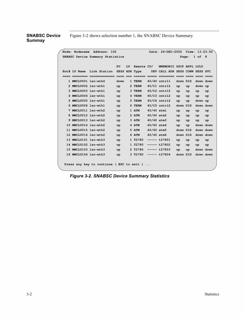
SNABSC Device Summay
Figure 3-2 shows selection number 1, the SNABSC Device Summary.
Figure 3-2. SNABSC Device Summary Statistics
Node: Nodename Address: 102 Date: 26-DEC-2002 Time: 13:23:50
SNABSC Device Summary Statistics Page: 1 of 8
PU LU Remote CU/ MNEMONIC SSCP APPL LULU
Ent# LU Name Link Station SESS ADR Type DEV CALL ADR SESS CONN SESS SVC
==== ======== ============= ==== === ====== ===== ======== ==== ==== ==== ====
1 MMCLU001 lsc-eth4 down 1 TERM 40/40 cntrl1 down DIS down down
2 MMCLU002 lsc-eth1 up 2 TERM 40/C1 cntrl2 up up down up
3 MMCLU003 lsc-eth1 up 3 TERM 40/C2 cntrl2 up up up up
4 MMCLU004 lsc-eth1 up 4 TERM 40/C3 cntrl2 up up up up
5 MMCLU005 lsc-eth1 up 5 TERM 40/C4 cntrl2 up up down up
6 MMCLU006 lsc-eth1 up 6 TERM 40/C5 cntrl2 down DIS down down
7 MMCLU011 lsc-eth2 up 1 ATM 40/40 atm1 up up up up
8 MMCLU012 lsc-eth2 up 2 ATM 40/40 atm2 up up up up
9 MMCLU013 lsc-eth2 up 3 ATM 40/40 atm3 up up up up
10 MMCLU014 lsc-eth2 up 4 ATM 40/40 atm4 up up down down
11 MMCLU015 lsc-eth2 up 5 ATM 40/40 atm5 down DIS down down
12 MMCLU016 lsc-eth2 up 6 ATM 40/40 atm6 down DIS down down
13 MMCLU101 lsc-eth3 up 1 T2780 ----- t27801 up up up up
14 MMCLU102 lsc-eth3 up 1 T2780 ----- t27802 up up up up
15 MMCLU103 lsc-eth3 up 2 T2780 ----- t27803 up up down down
16 MMCLU104 lsc-eth3 up 3 T2780 ----- t27804 down DIS down down
Press any key to continue ( ESC to exit ) ...
3-2 Statistics

Detailed SNA Device Statistics
Detailed Device Statistics can be viewed by:
• LU Name• Entry Number
LU Name Figure 3-3 shows the SNA Features Statistics Menu. To view the SNABSC Device Statistics by LU Name, enter selection number 3. You are prompted to type in the SNABSC LU Name.
Figure 3-3. Detailed SNABSC Device Statistics by LU Name
Node: nodename Address: (blank) Date: 12-JAN-01 Time: 7:19:29
Menu: SNA Feature Statistics Path:
1. SNABSC Device Summary2. SNABSC Device Summary for LLC Station3. Detailed SNABSC Device Statistics by LU Name4. Detailed SNABSC Device Statistics by Entry Number5. Reset SNA-DSP/SES Device Statistics by LU Name6. Reset SNA-DSP/SES Device Statistics by Entry Number
#Enter Selection: 3SNABSC LU name:
Prompt for entering LU Name
Statistics 3-3
T0101-08, Revision F Release 6.4

Detailed SNABSC Device Statistics - Page 1
Figure 3-4 shows page 1 of the Detailed SNABSC Device Statistics. Enter selection number 4 to view the statistics by entry number. SNA can have two parallel sessions running at the same time, as shown on this page.
Figure 3-4. Page 1 of the Detailed SNABSC Device Statistics viewed by Entry Number
Node: Nodename Address: 102 Date: 26-DEC-2002 Time: 16:20:40
Detailed SNABSC Device Statistics Page: 1 of 2
LU Name: MMCLU004 LU Address: 4
LinkStn: lsc-eth1 Device Entry is ENABLED
SSCP-PU Session State : Active SSCP-LU Session State : Active
LU-LU Session State : Active
SSCP-LU Detailed Session Statistics:
RU Summary: Send Receive Data Summary: IN OUT
RU Size: 0 0 Data Frames: 8 8
Max BTU Size: 1033 1033 FMD Frames: 8 8
Current Window Size: 0 0 Data Bytes: 254 62
Max Window Size: 0 0 FMD Bytes: 0 0
LU-LU Detailed Session Statistics:
RU Summary: Send Receive Data Summary: IN OUT
RU Size: 1024 3840 Data Frames: 5 0
Max BTU Size: 1033 1033 FMD Frames: 5 0
Current Window Size: 0 0 Data Bytes: 979 0
Max Window Size: 0 0 FMD Bytes: 0 0
Press any key to continue ( ESC to exit ) ...
3-4 Statistics

Detailed SNABSC Device Statistics - Page 2
Figure 3-5 shows Page 2 of the Detailed SNABSC Device Statistics viewed by entry number:
Figure 3-5. Page 2 of the Detailed SNABSC Device Statistics
NoteWhen “SNABSC-DSP/SES State:” shows Connection Pending, or when attemping a connection, the detailed Call Summary shows a blank time stamp for that device.
Figure 3-6. Blank Time Stamp
Node: Nodename Address: 102 Date: 26-DEC-2002 Time: 16:22:25
Detailed SNABSC Device Statistics Page: 2 of 2
LU Name: MMCLU004 LU Address: 4
LinkStn: lsc-eth1 Device Entry is ENABLED
Remote Device Type: TERM Calling Address Configured: (None)
Destination CU Addr/Dev Addr: C1 40
LUA-SNABSC State: LU-LU Session SNABSC-DSP State: Connected
BIND Receive: 2 BIND Accept: 2 BIND Parameter Rej: 0
FM Profile: 3 TS Profile: 3 LU Type: 2
Outb FC: OFF Inb FC: OFF Last Outb LU-LU Seq # Rcv (Hex): 0001
SNABSC-DSP Detailed Statistics:
IN OUT IN OUT
Call Request: 0 7 Turbo Data Packets: 0 0
Call Accept: 1 0 Data Packets: 2 4
Call Reject: 6 0 Data Bytes: 35 1177
Session Disconnect: 0 0 Terminal Status: 1 0
Msg Seq# Resynced: 0 0 Cmd/Rsp Abort: 0 0
Circuit Disconnect: 0 0 Cmd/Rsp Fwd Abort: 0 0
Invite to Clear: 0 0 Unknown Disconnect: 0 0
Press any key to continue ( ESC to exit ) ...
Statistics 3-5
T0101-08, Revision F Release 6.4

Reset SNA-DSP/SES Device Statistics
You can reset the SNA-DSP/SES Device statistics by:
• LU Name• Entry Number
LU Name Figure 3-7 shows the SNA Features Statistics Menu. If you would like to Reset SNA-DSP/SES Device Statistics by LU Name, enter selection number 5. You are prompted to type in the SNABSC LU Name.
Figure 3-7. Reset SNA-DSP/SES Device Statistics by LU Name
Node: nodename Address: (blank) Date: 12-JAN-01 Time: 7:19:29
Menu: SNA Feature Statistics Path:
1. SNABSC Device Summary2. SNABSC Device Summary for LLC Station3. Detailed SNABSC Device Statistics by LU Name4. Detailed SNABSC Device Statistics by Entry Number5. Reset SNA-DSP/SES Device Statistics by LU Name6. Reset SNA-DSP/SES Device Statistics by Entry Number
#Enter Selection: 5SNABSC LU name:
Prompt for entering LU Name
3-6 Statistics

Reset SNA-DSP/SES Device Statistics - Page 2
Figure 3-8 shows Page 2 of the Reset SNA-DSP/SES Device Statistics viewed by entry number. Under the DSP Detailed Statistics on this page, all IN/OUT numbers under the Control Summary and Data Summary have been reset to zero.
Figure 3-8. Page 2 of the Reset SNA-DSP/SES Device Statistics
LU Name: MMCLU100 LU Address: 100 LU Type: IBM-3278-2
LinkStn: lsc-eth1
Remote Device Type: T2780INT Calling Address Configured: 102001100
Destination CU Addr/Dev Addr: 40 40
LUA-SNABSC State: SSCP-LU Session SNA-DSP/SES State: Disconnected
SNA-DSP/SES Detailed Statistics:
Control Summary: Data Summary:
IN OUT IN OUT
Call Request: 0 0 Turbo Data Packets:0 0
Call Accept: 0 0 Data Packets: 0 0
Call Reject: 0 0 Data Bytes: 0 0
Session Disconnect: 0 0 Terminal Status: 0 0
Msg Seg# Resynced: 0 0 Cmd/Rsp Abort: 0 0
Circuit Disconnect: 0 0 Cmd/Rsp Fwd Abort: 0 0
Invite to Clear: 0 0
Unknown Disconnect: 0 0
LUA-SNABSC Detailed Statistics:
BIND Receive: 0 BIND Accept: 0 BIND Parameter Rej: 0
Last Outbound LU-LU Sequence # Receive (Hex): 0000
Press any key to continue (ESC to exit) ...
Reset to zero
Statistics 3-7
T0101-08, Revision F Release 6.4

Screen Terms The screen terms are described in this table:
Term Description
APPL Connected Indicates the current status:• up: User Enabled connection• down: User Disabled connection
BIND Accept Number of BINDs accepted
BIND Parameter Rej Total number of BINDs rejected due to invalid parameters
BIND Receive Total number of BINDs received from SNA Host
Call Request Makes call connection
Call Accept Accepts call
Call Reject Rejects call
Circuit Disconnect Logical Disconnect
Cmd/Rsp Abort Abort command being received from or sent to DSP
Cmd/Rsp Fwd Abort Abort command being received from or sent to DSP
Data Bytes Total number of characters received from or sent to DSP
Invite to Clear Request to clear
Link Station Link Station type
Last Outbound LU-LU Sequence # Receive
Sequence number of the last RU received from the SNA Host
LU Address This is the Logical Unit (LU) identification number
LU-LU Session Indicates the current status:• up: Device is connected to the host application• down: Device is not connected to the host
application
LU Model Logical Unit Model number
LU Name This is the name of the Logical Unit (LU)
Msg Seg# Resynced Command to resync numbers
SSCP-LU Session Indicates the current status:• up: Node is connected to the SSCP host• down: Node is not connected to the SSCP host
RU Summary Request Unit Summary
RU Request Unit
Session Disconnect Disconnects from the network
Unknown Disconnect Disconnects from the network
3-8 Statistics

Appendix ASNA Sense Codes
Overview
Introduction This appendix provides descriptions for the SNA Sense Codes.
SNA Sense Codes A-1

Error Codes from Networks and Remote Devices
Error Codes from Networks and Remote Devices
Introduction Error codes received by SNA/BSC Conversion from X.25 network or remote devices are displayed through alarms or sense codes sent to the SNA host in UNBIND command. There are four types of codes, three already implemented for X.25, and one from BSC3270-to-BSC2780 to SNABSC Conversion. Below are the codes (symbols):
• EE - Event Code (X.25)• DD - Diagnostic Code (X.25)• CC - Cause Code (X.25)• SS - Specific Reason Code (BSC3270/BSC2780-to-SNABSC Conversion)
A-2 SNA Sense Codes

Error Codes from Networks and Remote Devices
AlarmsThe alarm displays the error code in the following format when there is disconnection from remote device:
Disconnection from DSP:
Nodename 27-JUN-2002 17:04 LU MMCLU002 DISC FROM DSP DEV (EE, DD, CC, SS)
Disconnection from SES:
Nodename 27-JUN-2002 17:04 LU MMCLU002 DISC FROM SES DEV (EE, DD, CC, SS)
NoteIf SS’s value is non-zero, then it has greater significance than DD and CC. Otherwise, DD and CC are the more significant code (even if either or both are 00).
SNA Sense Codes A-3
T0101-08, Revision F Release 6.4

Error Codes from Networks and Remote Devices
SNA Sense Code in Inbound UNBINDThe following table describes SNA UNBIND command format with the sense code:
UNBIND Sense Code Format
The UNBIND can only be sent after a LU-LU session is established and where UNBIND (instead of LUSTAT, for example) is used to inform SNA Host of disconnection. Where UNBIND is not used, alarms (described above) must be used to determine the cause of disconnection or unsuccessful Call Request.
The sense code is formatted in inbound (to SNA Host) UNBIND command to indicate DSP or SES and any possible reason for disconnect from device.
Byte 0 (RU2)
- bits 0-3: always '0000'- bits 4-7: always '1000'
Byte 1 (RU3)
- bits 0-3: always '1111'- bits 0-1: '00' - from DSP
'01' - from SES- bits 2-3: '00' - Bytes 2-3 contain Specific Code
'01' - Event is SASD*; byte 2 contains Diagnostic Code and byte 3 contains the Cause Code'10' - Event is SASCBB*; bytes 2 contains Diagnostic Code and bytes 3contains the Cause Code'11' - Event is SACD*; bytes 2 and bytes 3 are reserved
Bytes 2 - 3 (RU4 - RU5)
Specific Code or Diagnostic/Cause Code
Sense Code Summary
The following tables list the Sense Code Summary by DSP, SES and Event:
Code Description
TH0 - TH5 Transmission Header
RH0 - RH2 Request/Response Header
RU0- x'32' UNBIND Command
RU1- x'FD' UNBIND Type
Note‘FD’ is unique to Vanguard Managed Solutions. ‘FD’ is not documented in IBM’s format manual.
RU2 - RU5 Sense Code
Code From Event Description
x'08F0 00SS' DSP SS = Specific Code
x'08F1 DDCC' DSP Event is SASD*; DD = Diagnostic Code; CC = Cause Code
A-4 SNA Sense Codes

Error Codes from Networks and Remote Devices
* Event Codes are described in the next section.
x'08F2 DDCC' DSP Event is SASCBB*; DD = Diagnostic Code; CC = Cause Code
x'08F3 DDCC' DSP Event is SACD*
x'08F4 00SS' SES SS = Specific Code
x'08F5 DDCC SES Event is SASD*; DD = Diagnostic Code; CC= Cause Code
x'08F6 DDCC' SES Event is SASCBB*; DD = Diagnostic Code; CC = Cause Code
Code From Event Description
SNA Sense Codes A-5
T0101-08, Revision F Release 6.4

Error Codes from Networks and Remote Devices
EE - Event Codes
Event Codes The following table lists the Event Codes:
NoteDetails of Diagnostic, Cause, and Specific Reason code are described in this section.
Code Description
X'05' - SASD Session Disconnect
X'06' - SASCBB SASCBB- Session Reject
X'07' - SACD Circuit Disconnect (DSP only)
A-6 SNA Sense Codes

Error Codes from Networks and Remote Devices
DD - Diagnostic Code
Diagnostic Codes The table below lists the Diagnostic Codes that are X.25 or network specific.
Code Description
X'00' Generic code; no additional information
X'01' Invalid P(S)
X'02' Invalid P(R)
X'10' Generic code; packet type invalid
X'11' Packet invalid in state R1
X'14' Packet invalid in state P1
X'15' Packet invalid in state P2
X'16' Packet invalid in state P3
X'17' Packet invalid in state P4
X'18' Packet invalid in state P5
X'1B Packet invalid in state D1
X'1D' Packet invalid in state D3
X'20' Generic code; packet not allowed
X'21' Unidentifiable packet
X'22' Call on logical one way channel
X'23' Invalid packet on PVC
X'26' Packet too short
X'27' Packet too long
X'29' Invalid bits in packet
X'2B' Unauthorized interrupt conf
X'2C' Unauthorized interrupt
X'30' Generic code; timer expired
X'31' Timer expired for incoming call
X'32' Timer expired for clear
X'33' Timer expired for reset
X'34' Timer expired for restart
X'40' Generic code; call set-up problem
X'41' Facilities/region code not allowed
X'42' Facilities/region parameter not allowed
X'43' Bad called address
X'44' Bad calling address
X'45' Invalid facilities length
SNA Sense Codes A-7
T0101-08, Revision F Release 6.4

Error Codes from Networks and Remote Devices
Network Specific The table below lists the Diagnostic Codes that are network specific:
X'46' Incoming call barred
X'47' No logical channel available
X'48' A call collision occurred
X'49' Duplicate facility requested
X'4A' Non-zero address length
X'4B' Non-zero facility length
X'4C' Facility not found when expected
X'51' Improper cause code from DTE
X'53' Inconsistent Q Bit setting
X'54' NUI Problem (e.g. invalid NUI)
X'78' Temporary routing problem
Code Description
Code Description
X'80' Call limit reached on node that was not the destination
X'81' Call limit reached on destination node
X'82' No LCN's available on node that was not the call destination
X'83' Call disconnected by the CTP
X'84' Link failure in intermediate node
X'85' Call passed through same node twice
X'86' Call passed through too many nodes
X'9A' (#) received a Restart at level 3
X'9C' (#) Rx DISC at level 2.
X'9D' (#) Rx DM at level 2.
X'9E' (#) Rx SABM at level 2.
X'9F' (#) Rx FRMR at level 2.
X'A0' (#) Rx invalid N(r). Tx FRMR.
X'A1' (#) Rx unsolicited F bit. Tx FRMR.
X'A2' (#) Rx unknown command. Tx FRMR.
X'A3' (#) Rx unknown response. Tx FRMR.
X'A4' (#) Rx I field too long for L1. Tx FRMR.
X'A5' (#) No response after N2 tries. Tx SABM.
X'AE' (#) Rx frame of incorrect size. Tx FRMR.
X'AF' (#) Address error, sent FRMR.
A-8 SNA Sense Codes

Error Codes from Networks and Remote Devices
X'B0' (#) Source port is in BusyOut state.
X'B1' (#) Destination port is in BusyOut state.
X'B2' (#) DCP reconnection attempt rejected. Do not retry
X'B3' /* */
X'B4' Cannot bring up a call when configuration is changing
X'B5' NS Feature invalid configuration - during table boot.
X'B6' (#) Call Request specified unacceptable resources
X'B8' (#) NUI Database problem (busy, timeout, congestion)
X'B9' Invalid Quality Of Service (QoS)
X'BA' Clear Request from a Voice end-point
X'BB' Call cleared by port configured for Redirection
Code Description
SNA Sense Codes A-9
T0101-08, Revision F Release 6.4

Error Codes from Networks and Remote Devices
CC - Cause Codes
Cause Codes The table below lists the Cause Codes that are X.25 or network specific:
For Clear Indication
Code Description
X'01' Number busy
X'03' Invalid facility request
X'05' Network congestion
X'09' Out of order
X'0B' Access barred
X'0D' Not obtainable
X'11' Remote procedure error
X'13' Local procedure error
X'15' RPOA out of order
X'19' Reverse charging acceptance not subscribed
X'21' Incompatible destination
X'29' Ship absent
X'3A' (#) control port intervention
For Reset Indication
Code Description
X'01' Out of order (P)
X'03' Remote procedure error
X'05' Local procedure error
X'07' Network congestion
X'09' Remote DTE operational (P)
X'0F' Network operational (P)
X'11' Incompatible destination
X'1D' Network out of order (P) / (P) -- may only be sent on PVCs
A-10 SNA Sense Codes

Error Codes from Networks and Remote Devices
For Restart Indication
Code Description
X'01' Local procedure error
X'03' Network congestion
X'07' Network operational
X'7F' Registration/cancellation confirmed
SNA Sense Codes A-11
T0101-08, Revision F Release 6.4

Error Codes from Networks and Remote Devices
SS - Specific Code
DSP Specific Codes
The tables below show the SS - Specific Codes from DSP:
Device Status Error Received
Code Description
x'01' Received Device Status error
Poll Responses
Code Description
x'10' Invalid poll response
x'11' Received ENQ in response to poll to term
x'12' Received WACK to a poll
Timed Out or Disabled
Code Description
x'20' Timed out - no response from term to message
x'21' Idle Device Timeout
x'22' Device disabled
x'23' Received RVI in response to Select
x'24' Received EOT in response to text
x'25' No response to Call Request
x'26' No Call Request from TPAD
Receive Error
Code Description
x'30' Response error from term to message
x'31' Receive error on first text from term
x'32' Receive error on partial text from term
x'33' Error on partial text from term
x'34' Receive error on term response to message
A-12 SNA Sense Codes

Error Codes from Networks and Remote Devices
SES Specific Code The tables below show the SS - Specific Codes from SES:
Send Error
Code Description
x'40' Received NAK to message to term
x'41' Received ENQ in response to message to term
Bad Acknowledgment
Code Description
x'50' Invalid ack0 from term to message
x'51' Invalid ack1 from term to message
x'52' Invalid response to message
x'53' Invalid response to select
Disconnect Key Received
Code Description
x'60' Disconnect key in response to poll
x'61' Disconnect key in response to select
x'62' Disconnect key in response to message
x'63' Disconnect key in response to ENQ
Disconnect from SNABSC
Code Description
x'70' Wrong SNA state
x'71' Retry Call Request due to no packet
x'72' Shutdown by Applications
x'73' Cannot Call Request due to no socket connection
Timed Out - Waiting for ACK to Line Bid
Code Description
x'01' Timed out - no line bid ACK from local
SNA Sense Codes A-13
T0101-08, Revision F Release 6.4

Timed Out - Waiting for Something from Local
Code Description
x'10' Timed out - no partial text from local
x'11' Timed out - no expected NAK from local due to bad BCC
x'12' Timed out - no expected ACK from local
x'13' Timed out - no expected ACK w/TID from local
x'14' Timed out - no text from local
x'15' Timed out - no ENQ (HID) from local
x'16' Timed out - no response to Call Request
x'17' Timed out - no Call Request from TPAD
Bad ACK0/ACK1 or NAK Sequence from Local
Code Description
x'20' Bad ACK0/ACK1 or NAK sequence from local
Unexpected EOT from Local
Code Description
x'30' Unexpected EOT from local
x'31' Unexpected EOT from local
x'32' Unexpected EOT received from local (EIA)
x'33' Unexpected EOT from local
Received Error on Text from Local
Code Description
x'40' Received error on first text from local
x'41' Received error on partial text from local
Disconnect from SNABSC
Code Description
x'50' Wrong SNA state
x'51' Retry Call Request due to no packet
x'52' Shutdown by Applications

Error Codes from Networks and Remote Devices
x'53' Cannot Call Request due to no socket connection
Disconnect from SNABSC
Code Description
2780 PAD is Re-Initialized
Code Description
x'60' 2780 PAD is re-initialized
Software Errors
Code Description
x'C0' Timed out - no expected NAK from local due to time out waiting for remote text
x'C1' Unexpected DISC from remote (EIA)
x'C2' Timed out - no text from remote
x'C3' Timed out - no flow control clear from remote side
x'C4' Timed out - no text ACK from remote
x'C5' Excessive WACK ENQs from local; due to no text ACK from remote
x'C6' Timed out - nothing from either direction
x'C7' Received Session Bound from remote but local issued a disconnect request
x'C8' Unexpected event waiting for ACK from remote
x'C9' Timed out - no ACK (TID) from remote
x'CA' Timed out - no ENQ (HID) from remote
x'CB' Bad event - no ENQ (HID) from remote
Unknown Reason
Code Description
x'FF' Unknown reason
SNA Sense Codes A-15
T0101-08, Revision F Release 6.4


Index
B
BSC 3270-to-SNAConfiguration Examples 2-1Description 1-1How it Works 1-7Start-up Sequence 1-10Support 1-3Typical Application 1-8Vanguard 6455 Requirements 2-5
C
Central Site Application 1-7Cessation 1-3
CESS+CESS3 1-3Configuration Parameters
APPN Node Table 2-24Ethernet Port 2-9Ethernet Station 2-13Frame Relay Station 2-13LLC Profile Table 2-20Node 2-6Port 2-6SNA to BSC 3270 Conversion Device Table 2-
25Station Records 2-11
D
Device Boot 1-15Device Disable 1-14Device Enable (ATM) 1-13
E
ExamplesConfiguration 2-1Device Boot 1-15Device Disable 1-14Device Enable 1-13Fail/Recovery 1-11Start-up Sequence 1-10Typical Application 1-8
L
LLC-SDLC Station Boot 1-17
O
OverviewBSC 3270 1-6System Network Architecture (SNA) 1-4
S
SNA Sense Code Descriptions A-1SNA Sense Codes 1-12Statistics 3-1
Reset SNABSC-DSP Device StatisticsLU Name 3-4
Screen Terms (statistics) 3-8SNABSC Device Statistics
Entry Number 3-4LU Name 3-3
SNABSC Device Summary 3-2
Index-1
