vapour recovery unit
TRANSCRIPT

Fundamentals of Vapor Recovery
“Waste Gas” IS LOST PRODUCTAnd LOST REVENUE
Presented by:Larry S. RichardsHy-Bon Engineering Co.


VAPOR RECOVERY VAPOR RECOVERY SYSTEMSSYSTEMS
What is Vapor Recovery?…A little history...

HISTORYHISTORY

OIL STORAGE FROM THE OIL STORAGE FROM THE PASTPAST

OPEN PIT OIL STORAGEOPEN PIT OIL STORAGE

EARLY TANKSEARLY TANKS

EARLY TANKSEARLY TANKS
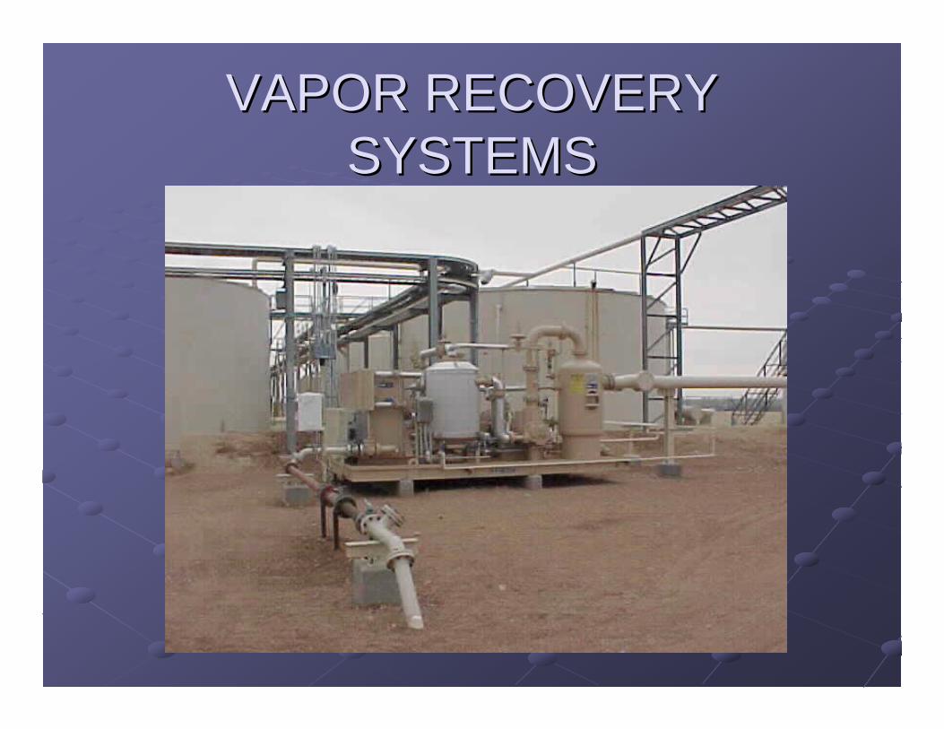
VAPOR RECOVERY VAPOR RECOVERY SYSTEMSSYSTEMS

TANK OPERATIONSTANK OPERATIONS
As the oil As the oil resides in resides in the tanks, it the tanks, it gives off gives off vapors, vapors, thereby thereby increasing increasing the pressure the pressure inside the inside the tank.tank.

Sources of Methane LossesSources of Methane LossesApproximately 26.6 Approximately 26.6 BcfBcf/yr of Methane /yr of Methane are lost from storage tanks are lost from storage tanks
Flash lossesFlash lossesoccur when crude is transferred from occur when crude is transferred from containment at a high pressure to containment containment at a high pressure to containment at a lower pressureat a lower pressure
Working lossesWorking lossesoccur when crude levels change and when occur when crude levels change and when crude in the tank is agitatedcrude in the tank is agitated
Standing lossesStanding lossesoccur with daily and seasonal temperature and occur with daily and seasonal temperature and pressure changespressure changes
Source: Natural Gas STAR PartnersSource: Natural Gas STAR Partners

PURPOSE• Vapor Recovery units are designed to comply with EPA standards, provide additional profits to the oil producer and eliminate the emission of stock tank vapors to the atmosphere.
• Most vapors contain varying amounts of methane, ethane, isopentane, propane, and butane and contribute to the gravity of lease crude.
• Dissipation of these products to the atmosphere on a conventional tank battery means a reduction in gravity of the liquid in the tank, thereby decreasing its value.
VAPOR RECOVERY VAPOR RECOVERY SYSTEMSSYSTEMS

ENVIRONMENTAL HAZARDSENVIRONMENTAL HAZARDSThis flare was This flare was causing a variety causing a variety of health and of health and environmental environmental concerns concerns –– a gas a gas stream now stream now generating over generating over $150,000 per $150,000 per month in month in additional additional revenue. Methane revenue. Methane gas has 23 times gas has 23 times the impact as a the impact as a greenhouse gas as greenhouse gas as CO2 CO2 –– although although almost 100% of almost 100% of industry focus is industry focus is currently on CO2.currently on CO2.

WHY LET $ ESCAPE INTO WHY LET $ ESCAPE INTO THE AIR?THE AIR?
Besides being an Besides being an environmental environmental hazard, escaping hazard, escaping vapors actually vapors actually cost the operator cost the operator money. What money. What money? money? UncapturedUncapturedprofits!! An profits!! An average tank average tank battery can emit battery can emit from $15,000 to from $15,000 to $50,000 in $50,000 in natural gas per natural gas per month!month!
$$
$$ $$ $$ $$

VAPOR RECOVERY VAPOR RECOVERY SYSTEMSSYSTEMS

Standard Vapor Recovery UnitStandard Vapor Recovery Unit
Crude Oil Stock
Tank(s)
ControlPilot
Vent LineBack Pressure
Valve
SuctionScrubber
SuctionLine
Condensate Return
BypassValve
ElectricControlPanel
Electric DrivenRotary Compressor
Gas SalesMeter Run
Gas
Liquid Transfer Pump
Check Valve
Sales
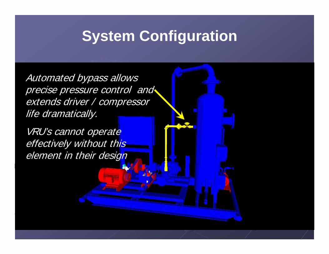
Automated bypass allows precise pressure control and extends driver / compressor life dramatically.
VRU’s cannot operate effectively without this element in their design
System Configuration

Automated liquid transfer systems are imperative due to the amount of condensate derived from this wet gas stream.
System Configuration

VAPOR RECOVERYVAPOR RECOVERY
Typical stock Typical stock tank vapor tank vapor recovery unit in recovery unit in operation. This operation. This unit is unit is configured to configured to capture 90 capture 90 mcfd of gas mcfd of gas and discharge and discharge into a 40 psig into a 40 psig sales line.sales line.

VRU Evaluation VRU Evaluation ChecklistChecklist

Is the unit on location a vapor Is the unit on location a vapor recovery unit ?recovery unit ?
Does it have a pressure sensing device on the Does it have a pressure sensing device on the tanks or on the skid?tanks or on the skid?Does it have a bypass system to circulate gas Does it have a bypass system to circulate gas between the compressor and the inlet or suction between the compressor and the inlet or suction vessel?vessel?Is the correct type of compressor being utilized? Is the correct type of compressor being utilized? (Rotary vane compressors, rotary screw (Rotary vane compressors, rotary screw compressors orcompressors or venturiventuri jet design recommended jet design recommended vs. reciprocating compressors)vs. reciprocating compressors)

Is the production system properly Is the production system properly configured to capture the vent gas?configured to capture the vent gas?
Is the piping from the tanks to the compressor Is the piping from the tanks to the compressor sloped downward with no visible liquid traps sloped downward with no visible liquid traps
(U in the piping)?(U in the piping)?Are the tanksAre the tanks manifoldedmanifolded together properly?together properly?Is a gas blanket being used?Is a gas blanket being used?Is the pressure sensing device sensing pressure Is the pressure sensing device sensing pressure off the top of the tanks? off the top of the tanks?

Benefits of Vapor Recovery Benefits of Vapor Recovery UnitsUnits
Capture up to 95 percent of Capture up to 95 percent of hydrocarbon vapors that accumulate hydrocarbon vapors that accumulate in tanksin tanksRecovered vapors have much higher Btu Recovered vapors have much higher Btu content than pipeline quality natural gascontent than pipeline quality natural gasRecovered vapors can be more valuable Recovered vapors can be more valuable than methane alonethan methane aloneReduce regulatory & liability exposureReduce regulatory & liability exposure

Criteria for VRU LocationsCriteria for VRU Locations
Steady source and sufficient quantity Steady source and sufficient quantity of lossesof losses
Available gathering systemAvailable gathering systemOutlet for recovered gasOutlet for recovered gas
Access to pipeline or onAccess to pipeline or on--site fuel usesite fuel useTank batteries that are subject to Tank batteries that are subject to state/federal air regulationsstate/federal air regulations

VRU Decision ProcessVRU Decision Process
Identify possible locations for VRUs
Quantify the volume of lossesQuantify the volume of losses
Determine the value of recoverable losses
Determine the cost of a VRU project
Evaluate VRU project economics

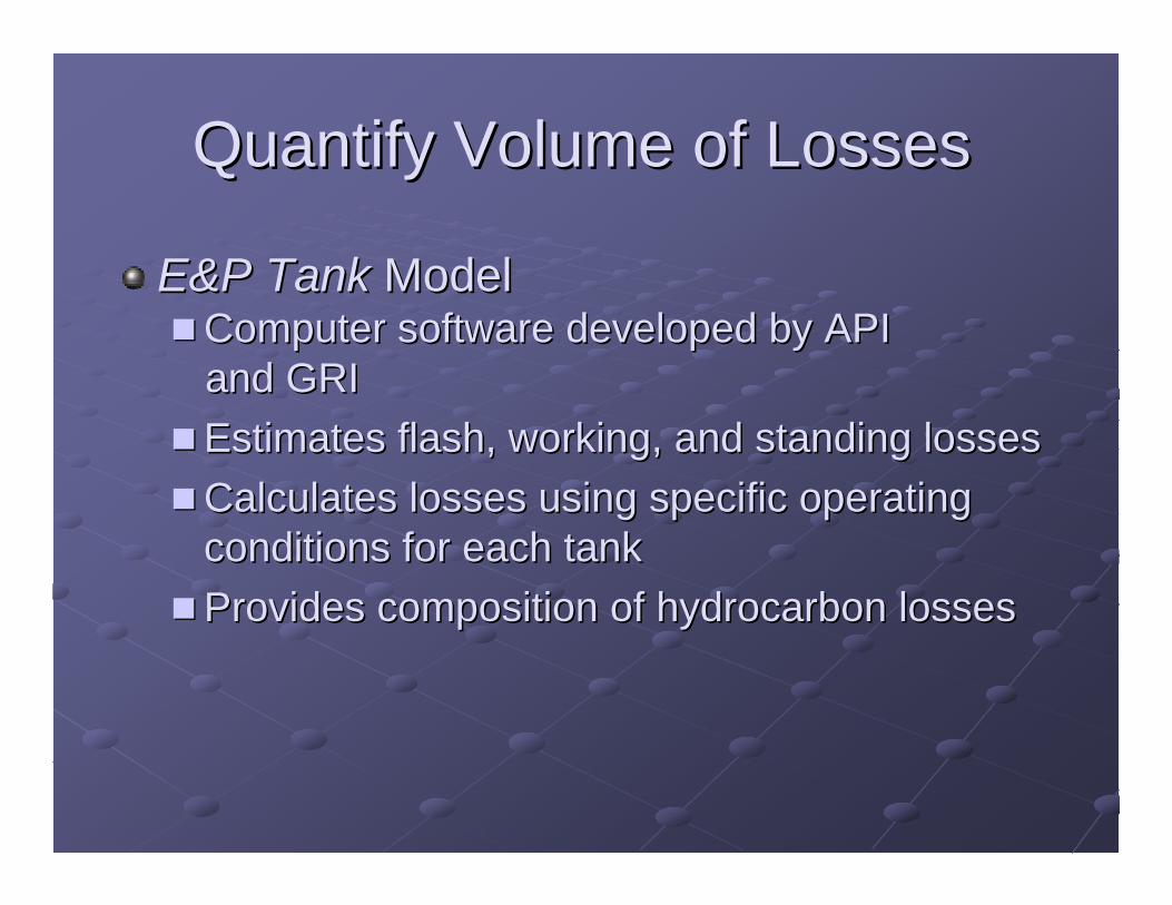
Quantify Volume of LossesQuantify Volume of Losses
Estimate losses from chart based on oil Estimate losses from chart based on oil characteristics, pressure, and temperature characteristics, pressure, and temperature at each locationat each locationEstimate emissions using the Estimate emissions using the E&P TankE&P TankModelModelMeasure losses using orifice well Measure losses using orifice well tester and recording manometertester and recording manometer

Estimated Volume of Tank Estimated Volume of Tank VaporsVapors
Pressure of Vessel Dumping to Tank (Psig)Pressure of Vessel Dumping to Tank (Psig)
Vap
or V
ente
d fro
m T
anks
Vap
or V
ente
d fro
m T
anks
-- SC
F/BB
L SC
F/BB
L -- G
OR
GO
R
110110
100100
9090
8080
7070
6060
5050
4040
3030
1010
2020
1010 2020 3030 4040 5050 6060 7070 8080
Under 30Under 30°° APIAPI
3030°° API to 39API to 39°° APIAPI4040°° API and Over
API and Over
4343

Estimating Tank EmissionsEstimating Tank Emissions
Example 1:Example 1:
Pressure of the Vessel dumping to the Pressure of the Vessel dumping to the tanks:tanks:
40 PSIG40 PSIGAPI Gravity of the Oil:API Gravity of the Oil:
4040Barrels of Oil through the battery per day: Barrels of Oil through the battery per day:
1,0001,000

Estimating Tank EmissionsEstimating Tank Emissions
Example 1:Example 1:
60 SCF per bbl X 1000 60 SCF per bbl X 1000 bbls bbls per day = per day =
60,000 SCFD or 60 mcfd of gas60,000 SCFD or 60 mcfd of gas
60 mcfd of gas X $6 per mcf = $360 per day60 mcfd of gas X $6 per mcf = $360 per dayor $10,800 per monthor $10,800 per month

Estimating Tank EmissionsEstimating Tank Emissions
Example 2:Example 2:
Pressure of the Vessel dumping to the Pressure of the Vessel dumping to the tanks:tanks:
70 PSIG70 PSIGAPI Gravity of the Oil:API Gravity of the Oil:
3535Barrels of Oil through the battery per day: Barrels of Oil through the battery per day:
500500
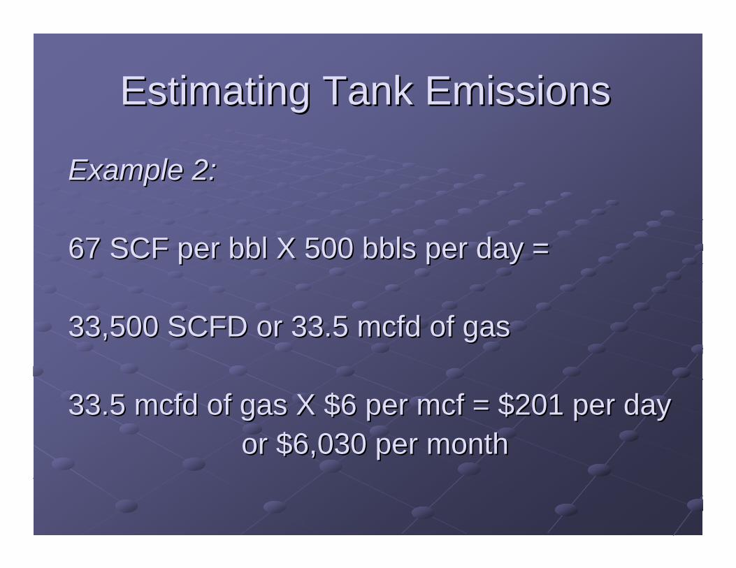
Estimating Tank EmissionsEstimating Tank Emissions
Example 2:Example 2:
67 SCF per bbl X 500 67 SCF per bbl X 500 bbls bbls per day = per day =
33,500 SCFD or 33.5 mcfd of gas33,500 SCFD or 33.5 mcfd of gas
33.5 mcfd of gas X $6 per mcf = $201 per day33.5 mcfd of gas X $6 per mcf = $201 per dayor $6,030 per monthor $6,030 per month

Estimating Tank EmissionsEstimating Tank Emissions
Chart method is a quick and easy way to get Chart method is a quick and easy way to get a fast ballpark estimatea fast ballpark estimate
Notice the impact of higher gravity oil, as well Notice the impact of higher gravity oil, as well as higher separator pressuresas higher separator pressures
This method is VERY CONSERVATIVE and This method is VERY CONSERVATIVE and generally underestimates actual emission generally underestimates actual emission levelslevels
Quantify Volume of LossesQuantify Volume of Losses
E&P TankE&P Tank ModelModelComputer software developed by API Computer software developed by API and GRIand GRIEstimates flash, working, and standing lossesEstimates flash, working, and standing lossesCalculates losses using specific operating Calculates losses using specific operating conditions for each tankconditions for each tankProvides composition of hydrocarbon lossesProvides composition of hydrocarbon losses

E&P TANK INPUT SCREENE&P TANK INPUT SCREEN


E&P TANK OUTPUT E&P TANK OUTPUT SCREENSCREEN


E&P TANK EXAMPLE E&P TANK EXAMPLE OUTPUTOUTPUT

-- Emission Composition ------------------------------------------------------------------
Component Uncontrolled Uncontrolled Controlled Controlled [ton/yr] [lb/hr] [ton/yr] [lb/hr]
H2S 12.137 2.771 0.607 0.139 O2 0.000 0.000 0.000 0.000 CO2 85.667 19.559 85.667 19.559 N2 2.284 0.521 2.284 0.521 C1 122.391 27.943 6.120 1.397 C2 159.072 36.318 7.954 1.816 C3 415.158 94.785 20.758 4.739 i-C4 96.442 22.019 4.822 1.101 n-C4 261.360 59.671 13.068 2.984 i-C5 82.901 18.927 4.145 0.946 n-C5 97.357 22.228 4.868 1.111 C6 28.130 6.422 1.407 0.321 C7 26.984 6.161 1.349 0.308 C8 10.294 2.350 0.515 0.118 C9 2.081 0.475 0.104 0.024 C10+ 0.544 0.124 0.027 0.006 Benzene 2.029 0.463 0.101 0.023 Toluene 0.250 0.057 0.013 0.003 E-Benzene 0.032 0.007 0.002 0.000 Xylenes 0.264 0.060 0.013 0.003 n-C6 19.202 4.384 0.960 0.219 224Trimethylp 0.000 0.000 0.000 0.000
Total 1424.579 325.246 71.229 16.262

-- Emission Summary ----------------------------------------------------------------------Item Uncontrolled Uncontrolled Controlled Controlled
[ton/yr] [lb/hr] [ton/yr] [lb/hr]
Total HAPs 21.780 4.973 1.089 0.249 Total HC 1324.491 302.395 66.225 15.120 VOCs, C2+ 1202.100 274.452 60.105 13.723 VOCs, C3+ 1043.029 238.134 52.151 11.907
Uncontrolled Recovery Info.
Vapor 71.3400 [MSCFD] HC Vapor 66.3900 [MSCFD] GOR 35.67 [SCF/bbl]

-- Emission Composition ------------------------------------------------------------------Component Uncontrolled Concontrolled Controlled Controlled
[ton/yr] [lb/hr] [ton/yr] [lb/hr] H2S 12.137 2.771 0.607 0.139 O2 0.000 0.000 0.000 0.000 CO2 85.667 19.559 85.667 19.559 N2 2.284 0.521 2.284 0.521 C1 122.391 27.943 6.120 1.397 C2 159.072 36.318 7.954 1.816 C3 415.158 94.785 20.758 4.739
i-C4 96.442 22.019 4.822 1.101 n-C4 261.360 59.671 13.068 2.984 i-C5 82.901 18.927 4.145 0.946 n-C5 97.357 22.228 4.868 1.111 C6 28.130 6.422 1.407 0.321 C7 26.984 6.161 1.349 0.308 C8 10.294 2.350 0.515 0.118 C9 2.081 0.475 0.104 0.024 C10+ 0.544 0.124 0.027 0.006 Benzene 2.029 0.463 0.101 0.023 Toluene 0.250 0.057 0.013 0.003 E-Benzene 0.032 0.007 0.002 0.000 Xylenes 0.264 0.060 0.013 0.003 n-C6 19.202 4.384 0.960 0.219 224Trimethylp 0.000 0.000 0.000 0.000
Total 1424.579 325.246 71.229 16.262

-- Stream Data ---------------------------------------------------------------------------No. Component MW LP Oil Flash Oil Sale Oil Flash Gas W&S Gas Total Emissions
mol % mol % mol % mol % mol % mol % 1 H2S 34.80 0.0508 0.0358 0.0065 0.6793 1.4580 1.0368 2 O2 32.00 0.0000 0.0000 0.0000 0.0000 0.0000 0.0000 3 CO2 44.01 0.2437 0.0950 0.0002 6.4933 4.6923 5.6664 4 N2 28.01 0.0102 0.0005 0.0000 0.4189 0.0235 0.2374 5 C1 16.04 0.9543 0.1553 0.0000 34.5319 7.6894 22.2079 6 C2 30.07 0.6701 0.3661 0.0087 13.4456 17.7009 15.3993 7 C3 44.10 2.1827 1.7950 1.0502 18.4760 37.9263 27.4061 8 i-C4 58.12 1.1269 1.0530 0.9606 4.2332 5.5332 4.8301 9 n-C4 58.12 4.6091 4.4328 4.2283 12.0182 14.3518 13.0896 10 i-C5 72.15 3.1066 3.1043 3.0959 3.2018 3.5131 3.3447 11 n-C5 72.15 5.0558 5.0864 5.1064 3.7713 4.1125 3.9280 12 C6 86.16 4.1726 4.2496 4.3162 0.9366 1.0199 0.9748 13 C7 100.20 10.3655 10.5937 10.7945 0.7742 0.8517 0.8098 14 C8 114.23 10.8426 11.0945 11.3173 0.2563 0.2861 0.2700 15 C9 128.28 5.5127 5.6428 5.7580 0.0450 0.0543 0.0492 16 C10+ 166.00 45.9695 47.0631 48.0331 0.0087 0.0106 0.0095 17 Benzene 78.11 0.5685 0.5803 0.5906 0.0723 0.0795 0.0756 18 Toluene 92.13 0.2132 0.2181 0.2224 0.0075 0.0084 0.0079 19 E-Benzene 106.17 0.0711 0.0728 0.0743 0.0008 0.0009 0.0009 20 Xylenes 106.17 0.6802 0.6962 0.7104 0.0068 0.0077 0.0072 21 n-C6 86.18 3.5939 3.6646 3.7261 0.6222 0.6798 0.6486 22 224Trimethylp 114.24 0.0000 0.0000 0.0000 0.0000 0.0000 0.0000
MW 123.89 125.93 127.59 37.91 45.66 41.47 Stream Mole Ratio 1.0000 0.9768 0.9570 0.0232 0.0197 0.0430 Heating Value [BTU/SCF] 2001.39 2458.73 2211.37 Gas Gravity [Gas/Air] 1.31 1.58 1.43 Bubble Pt. @ 100F [psia] 56.28 20.19 8.70 RVP @ 100F [psia] 18.38 11.68 7.71 Spec. Gravity @ 100F 0.800 0.803 0.806

TANK TESTTANK TESTA chart recorder is set up on the tank battery for a 24-hour pressure test. The resultant chart is brought into the office for evaluation. Information such as ambient temperature, test apparatus size and orifice size is recorded and used in the calculation of volume of tank vapors.

TANK TESTTANK TEST
Ultrasonic meters and Mass flow meters are also highly effective
The key is DURATION – a minimum of 24 hours of emissions must be charted for accurate results

What is the Recovered Gas What is the Recovered Gas Worth?Worth?
Value depends on BTU content of gasValue depends on BTU content of gasValue depends on how gas is usedValue depends on how gas is used
OnOn--site fuel site fuel -- measured in terms of fuel that measured in terms of fuel that no longer must be purchasedno longer must be purchasedNatural gas pipeline Natural gas pipeline -- measured by the higher measured by the higher price for rich (higher Btu) gas (=2.5 X)price for rich (higher Btu) gas (=2.5 X)Gas processing plant Gas processing plant -- measured by sale of measured by sale of NGLs and methane, which can be separatedNGLs and methane, which can be separated
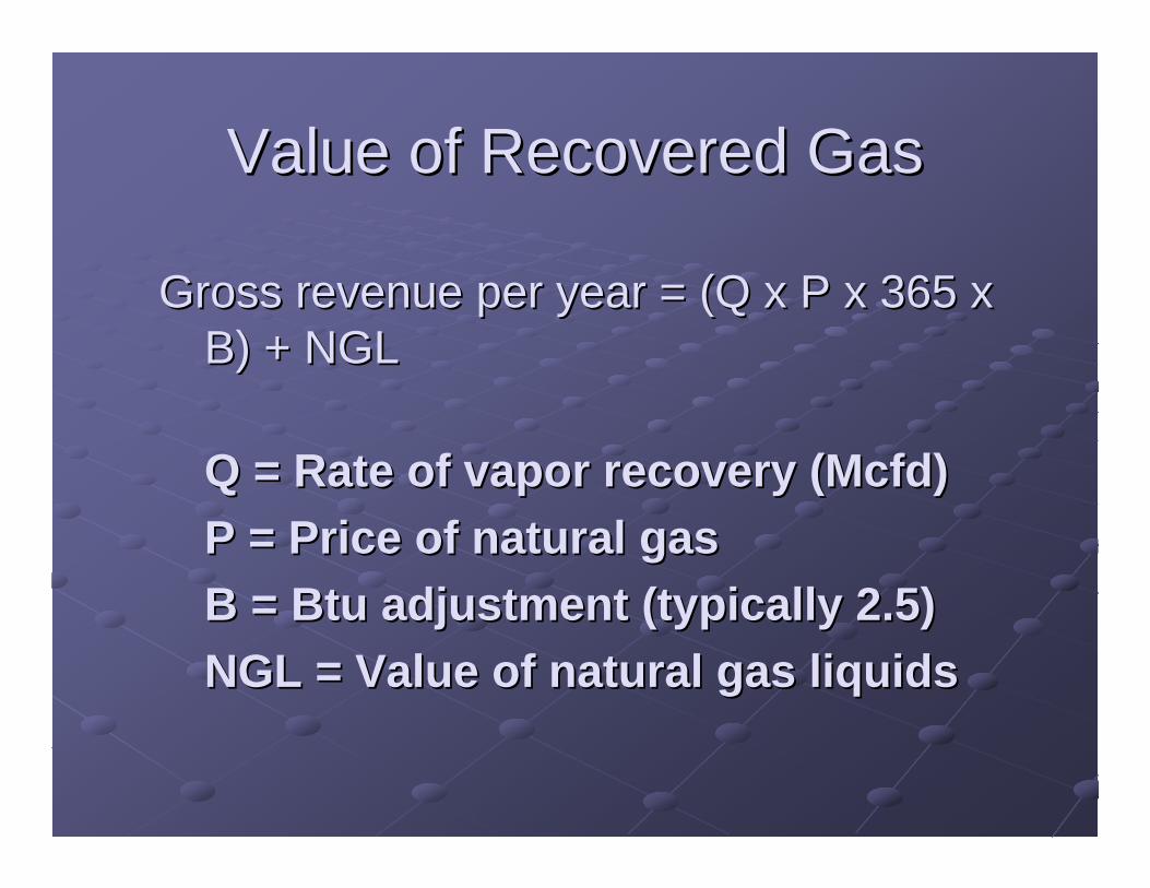
Value of Recovered GasValue of Recovered Gas
Gross revenue per year = (Q x P x 365 x Gross revenue per year = (Q x P x 365 x B) + NGLB) + NGL
Q = Rate of vapor recovery (Mcfd)Q = Rate of vapor recovery (Mcfd)P = Price of natural gasP = Price of natural gasB = Btu adjustment (typically 2.5)B = Btu adjustment (typically 2.5)NGL = Value of natural gas liquidsNGL = Value of natural gas liquids

Estimating Tank EmissionsEstimating Tank Emissions
Example 1:Example 1:
60 SCF per bbl X 1000 60 SCF per bbl X 1000 bbls bbls per day = per day = 60,000 SCFD or 60 mcfd of gas60,000 SCFD or 60 mcfd of gas60 mcfd of gas X $6 per mcf = $360 per day60 mcfd of gas X $6 per mcf = $360 per day
or $10,800 per monthor $10,800 per month
60 mcfd X $6 X 2.5 + 2 60 mcfd X $6 X 2.5 + 2 bblsbbls/thousand ($100) = /thousand ($100) =
$1,000 per day or $30,000 per month$1,000 per day or $30,000 per month
Estimating Tank EmissionsEstimating Tank Emissions
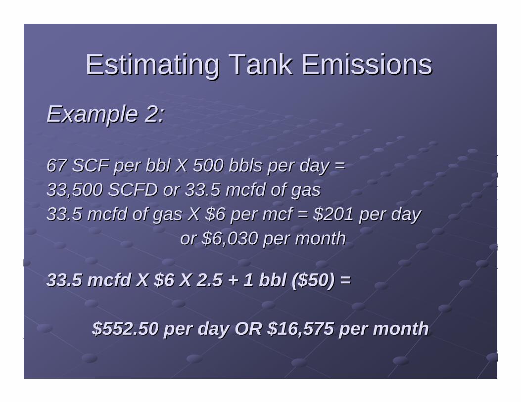
Example 2:Example 2:
67 SCF per bbl X 500 67 SCF per bbl X 500 bbls bbls per day = per day = 33,500 SCFD or 33.5 mcfd of gas33,500 SCFD or 33.5 mcfd of gas33.5 mcfd of gas X $6 per mcf = $201 per day33.5 mcfd of gas X $6 per mcf = $201 per day
or $6,030 per monthor $6,030 per month
33.5 mcfd X $6 X 2.5 + 1 bbl ($50) = 33.5 mcfd X $6 X 2.5 + 1 bbl ($50) =
$552.50 per day OR $16,575 per month$552.50 per day OR $16,575 per month

Cost of a VRU (contCost of a VRU (cont’’d)d)
Vapor Recovery Units Sizes and Costs
Capacity (Mcfd)
Compressor Horsepower
Median Capital
Costs ($)Installation Costs ($)
O&M Costs ($/year)
25 5 – 10 15,125 7,560 – 15,125 5,250
50 10 – 15 19,500 9,750 – 19,500 6,000
100 15 – 25 23,500 11,750 – 23,500 7,200
200 30 – 50 31,500 15,750 – 31,500 8,400
500 60 – 80 44,000 22,000 – 44,000 12,000
Note: Cost information provided by Partners and VRU manufacturers.
Source: Natural Gas Star Partners

What Is the Payback?What Is the Payback?Financial Analysis for VRU Projects
Peak Capacity
(Mcfd)
Installation & Capital Costs1 ($)
O&M Costs
($/year)
Value of Gas2
($/year) Payback3
Return on Investment4
(%)
25 26,470 5,250 25,869 1 yrs, 4 mos 73
50 34,125 6,000 51,738 9 mos 132
100 41,125 7,200 103,477 7 mos 234
200 55,125 8,400 206,955 3 mos 360
500 77,000 12,000 465,648 2 mos 589 1 Unit cost plus estimated installation cost of 75% of unit cost. 2 $5.67 per Mcf x ½ capacity x 365. Assumed price includes value of Btu-enriched gas (1,285 Btu/scf). 3 Based on 10% discount rate for future savings. Excludes value of recovered gas liquids. 4 Calculated for 5 years.
Source: Natural Gas Star Partners

To evaluate this practice for your situation, fill in the values below and click "Calculate Results".
NATURAL GAS & CRUDE OIL TANK VALUESPressure of the vessel dumping to the tank (PSIG)
API gravity (degrees)
Amount of crude oil cycled through the tank (bbl/d)
Number of days per year the Vapor Recovery Unit will be operated (days/yr)
CALCULATE CAPITAL AND O&M COST ESTIMATESClick to calculate estimates for capital equipment costs and O&M costs.
23 psi
42 api gravity
2,000 bbl/day
351 days
Calculate
EPA Website – PRO Tools

EPA Website – PRO ToolsCAPITAL EQUIPMENT AND O&M COSTS
Enter your own values for the capital equipment listed below or accept the estimates.
Vapor Recovery Unit cost ($) $30,068
Vapor Recovery Unit installation cost ($) $22,551
Depreciable life of equipment (Years) 10
Vapor Recovery Unit O&M cost ($/year) $8,649
http://www.ergweb.com/gasstar/analytical_tool/VaporRecovery.asp

GENERAL ECONOMIC VALUES
Natural gas cost ($/Mcf)
Natural gas cost escalator (%)
O&M cost escalator (%)
Discount rate (%)
Marginal tax rate* (%)
Investment tax credit (%)
Working interest for capital costs (%)
Working interest for O&M costs (%)
Working interest for gas savings (%)
EPA Website – PRO Tools
Each variable can be added based on your companies specific conditions and contract terms

Gas emission reduction5 Year gas savings 141,453
(mcf)First Year gas savings 28,291
Without-tax effect5 Year NPV $504,434Payback (Years) 0.36DCFIRR 279%Simple ROI 279%
With-tax effect5 Year NPV (AT) $350,477Payback (AT) (Years) 0.47DCFIRR (AT) 208%Simple ROI (AT) 201%
Analysis results for:INSTALLING VAPOR RECOVERY UNITS ON CRUDE OIL STORAGE TANKS
To save this specific case for viewing in the Results Summary page, provide a name and click "Save"
EPA Website – PRO Tools


Other Costs to ConsiderOther Costs to ConsiderRegulatory Liability ExposureRegulatory Liability ExposurePublic Relations ExposurePublic Relations Exposure
Positive or NegativePositive or NegativeLitigation ExposureLitigation Exposure
BP and Shell lawsuitsBP and Shell lawsuits
Producing a clean energy source (natural gas)Producing a clean energy source (natural gas)and simultaneously improving air quality in the and simultaneously improving air quality in the community community –– with an economic payback of with an economic payback of usually less than 3 monthsusually less than 3 months

HYHY--BON ENGINEERING BON ENGINEERING COMPANY, INC.COMPANY, INC.
Setting a New Standard!!Setting a New Standard!!

Technical Solutions for Capturing Vented Stock Tank
Gas
“Waste Gas” IS LOST PRODUCTAnd LOST REVENUE
Presented by:Larry S. RichardsHy-Bon Engineering Co.

CASE STUDIESCASE STUDIES

1000 MSCFD500 psi1131 BTU/cu. ft
70 MSCFD80 psi1401 BTU/cu. ft
90 MSCFD25 psi1588 BTU/cu. ft
100 MSCFD0 psi2534 BTU/cu. ft
Vented
Vented
Vented
$5.00 x 1.13 x
1000 MSCFD = $5650
$5.00 x 0 MSCFD = $0
$5.00 x 0 MSCFD = $0
$5.00 x 0 MSCFD = $0
TOTAL GAS SALES = $5650

THE SOLUTIONTHE SOLUTION
A system was designed to allow the customer to A system was designed to allow the customer to capture the vented gas from all phases of his capture the vented gas from all phases of his separation process. A multiseparation process. A multi--stage unit was stage unit was
designed and built that took the gas from the tank designed and built that took the gas from the tank vapors at atmospheric pressure, gathered the vent vapors at atmospheric pressure, gathered the vent
gas from the other separators and delivered the gas from the other separators and delivered the stream to the sales line at 500 psig.stream to the sales line at 500 psig.

Crude Oil Crude Oil AnalysisAnalysis
600 PSIG 600 PSIG SEPARATIONSEPARATION

500 PSIG 500 PSIG SEPARATIONSEPARATION
At 500 psig At 500 psig separation pressure separation pressure the gas has a BTU the gas has a BTU content of 1131 content of 1131 BTU/cu. ft.BTU/cu. ft.
80 PSIG 80 PSIG SEPARATIONSEPARATION
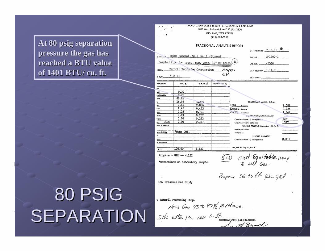
At 80 psig separation At 80 psig separation pressure the gas has pressure the gas has reached a BTU value reached a BTU value of 1401 BTU/ cu. ft.of 1401 BTU/ cu. ft.

25 PSIG 25 PSIG SEPARATIONSEPARATION
At 25 psig At 25 psig separation, the gas separation, the gas stream is at its stream is at its richest point yet, richest point yet, with a BTU value with a BTU value of 1588 BTU/cu. ft.of 1588 BTU/cu. ft.

OIL TANK OIL TANK STORAGESTORAGE
This gas stream This gas stream reaches its most reaches its most valuable point valuable point during storage in during storage in the oil tank. This the oil tank. This gas has a BTU value gas has a BTU value of 2514 BTU/ cu. Ft. of 2514 BTU/ cu. Ft. Obviously, this gas Obviously, this gas is worth capturing!is worth capturing!

1000 MSCFD500 psi1131 BTU/cu. ft
70 MSCFD80 psi1401 BTU/cu. ft
90 MSCFD25 psi1588 BTU/cu. ft
100 MSCFD0 psi2534 BTU/cu. ft
Recovered
Recovered
Recovered
$5.00 x 1.13 x
1000 MSCFD = $5650
$5.00 x 1.40 x
70 MSCFD = $490
$5.00 x 1.59 x
90 MSCFD = $716
$5.00 x 2.53 x
100 MSCFD = $1267
TOTAL GAS SALES = $8123
Multi-Stage Gas Booster
VRU
MONTHLY GAS SALES INCREASE
= $74,190

Case Study 2Case Study 2Mid Size Independent in Hobbs, NM area March Mid Size Independent in Hobbs, NM area March ‘‘0404Installation of 2Installation of 2 VRUVRU’’ss on 2 stock tank batteries, each emitting on 2 stock tank batteries, each emitting
approximately 90 MSCFD of 2500 approximately 90 MSCFD of 2500 btu btu tank vapors / 45 psig sales tank vapors / 45 psig sales lineline
Previous gas sales revenue: $0 (venting)Previous gas sales revenue: $0 (venting)
Monthly gas revenue: $5 X 2.5 X 90 MSCFD X 30 daysMonthly gas revenue: $5 X 2.5 X 90 MSCFD X 30 daysx 2 tanks = $ 67,500x 2 tanks = $ 67,500
Capital expense: $24,000 X 2 units = $48,000 Capital expense: $24,000 X 2 units = $48,000
Payback: 21 DAYSPayback: 21 DAYS

Producing
Well
Heater
1000 MSCFD
800 psi
1000 BTU/cu.ft.
Glycol Unit
60 MSCFD
100 psi
1200 BTU/cu.ft.
Flared
90 MSCFD
0 psi
2000 BTU/cu.ft.
Flared
Gas
Sales
Gross Sales
Per Day
$5.00 x 1000 MSCFD = $5000
$5.00 x 0 MSCFD = $0
$5.00 x 0 MSCFD = $0
TOTAL GAS SALES = $5000
Price Based upon $5.00/MMBTU
Case
Study 3

Heater
Producing
Well
1000 MSCFD
800 psi
1000 BTU/cu.ft.
60 MSCFD
100 psi
1200 BTU/cu.ft.
90 MSCFD
0 psi
2000 BTU/cu.ft.
Glycol Unit Gas
Sales
Gross Sales
Per Day
$5.00 x 1000 MSCFD = $5000
$5.00 x 1.2 x60 MSCFD = $360
$5.00 x 2.0 x 90 MSCFD = $900
TOTAL GAS SALES = $6260
Price Based upon $5.00/MMBTU
RECOVERED
RECOVERED
Gas Booster
VRU
MONTHLY GAS SALES INCREASE = $37,800
Case
Study 3
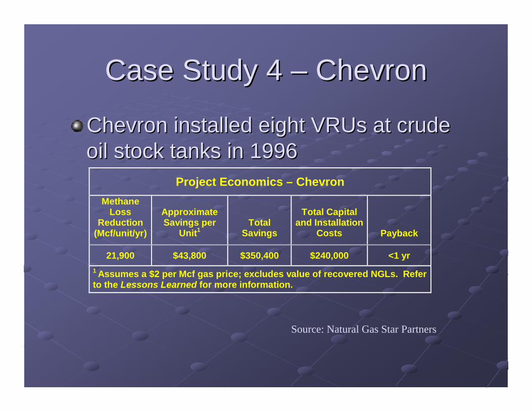
Case Study 4 Case Study 4 –– ChevronChevron
Chevron installed eight VRUs at crude Chevron installed eight VRUs at crude oil stock tanks in 1996oil stock tanks in 1996
Project Economics – Chevron Methane
Loss Reduction
(Mcf/unit/yr)
Approximate Savings per
Unit1
Total Savings
Total Capital and Installation
Costs
Payback
21,900 $43,800 $350,400 $240,000 <1 yr 1 Assumes a $2 per Mcf gas price; excludes value of recovered NGLs. Refer to the Lessons Learned for more information.
Source: Natural Gas Star Partners

Case Study 5Case Study 5Large Independent in North Texas in June Large Independent in North Texas in June ‘‘0404Installation of 1 VRU on a stock tank battery emitting approximaInstallation of 1 VRU on a stock tank battery emitting approximately 190 tely 190
MSCFD of 2400 MSCFD of 2400 btu btu tank vapors / 50 psig sales linetank vapors / 50 psig sales line
Previous gas sales revenue: $0 (venting)Previous gas sales revenue: $0 (venting)
Monthly gas revenue: $5 X 2.4 X 190 MSCFD X 30 daysMonthly gas revenue: $5 X 2.4 X 190 MSCFD X 30 days= $ 68,400= $ 68,400
Capital expense: $32,000 Capital expense: $32,000
Payback: 14 DAYSPayback: 14 DAYS

Other Emission SourcesOther Emission Sources
Gas can also be Gas can also be captured from captured from separators and separators and other field other field equipment. equipment. This unit is This unit is capturing natural capturing natural gas off several gas off several separators for separators for sale down a high sale down a high pressure line.pressure line.

Other Emission SourcesOther Emission Sources
This unit captures This unit captures a 98% CO2 gas a 98% CO2 gas stream in a field stream in a field outside Snyder, outside Snyder, Texas. Flooded Texas. Flooded screw compressor screw compressor for volumes to 1.5 for volumes to 1.5 MMSCFD. The CO2 MMSCFD. The CO2 is captured and reis captured and re--injected into the injected into the formation, formation, dramatically dramatically reducing reducing operating costs.operating costs.

COMPRESSOR COMPRESSOR SELECTION CRITERIASELECTION CRITERIA
HOW DO WE CHOOSE THE HOW DO WE CHOOSE THE APPROPRIATE COMPRESSOR?APPROPRIATE COMPRESSOR?

TYPICAL COMPRESSOR TYPES TYPICAL COMPRESSOR TYPES USED IN LOW PRESSUREUSED IN LOW PRESSURE
Rotary Vane Rotary Vane CompressorsCompressors
Eccentrically mounted Eccentrically mounted rotorrotorCentrifugal force Centrifugal force causes vanes to slide in causes vanes to slide in or outor outGas is forced into Gas is forced into decreasing space decreasing space thereby causing thereby causing compressioncompressionJacket water cooling Jacket water cooling systemsystemRPM range 400 to 1600RPM range 400 to 1600

ROTARY VANE OPERATING ROTARY VANE OPERATING PRINCIPLEPRINCIPLE
Gas enters the suction flange at low pressure. The rotor is mounted eccentrically toward the bottom of the compressor. Centrifugal force imparted as the rotor turns forces the blades out against the cylinder wall. The gas is forced into a ever decreasing space, thereby compressing the gas which then exits the discharge. The rotor clearance at the bottom (typically .005”) is sealed with lubricating oil to create a closed system within the cylinder.


Rotary Vane Compressor Rotary Vane Compressor Typical Operating ParametersTypical Operating ParametersDifferential pressure Differential pressure equal to or less than equal to or less than 60 psig (for single60 psig (for single--stage models).stage models).Volume from Volume from approximately 15 approximately 15 MSCFD to 2 MSCFD to 2 MMSCFD (for singleMMSCFD (for single--compressor units).compressor units).Relatively low suction Relatively low suction temperatures temperatures (< 120(< 120°° F)F)

Rotary VanesRotary Vanes
AdvantagesAdvantages•• Excellent for relatively high volumes and relatively Excellent for relatively high volumes and relatively
low differential pressureslow differential pressures•• Efficient at low pressuresEfficient at low pressures•• Can handle wet gas relatively easyCan handle wet gas relatively easy•• Comparatively low initial cost and ongoing Comparatively low initial cost and ongoing
maintenancemaintenanceDisadvantagesDisadvantages•• Limited as to discharge pressureLimited as to discharge pressure•• Limited as to suction temperature capabilitiesLimited as to suction temperature capabilities•• Free liquid causes blade breakage problemsFree liquid causes blade breakage problems

TYPICAL COMPRESSOR TYPES TYPICAL COMPRESSOR TYPES USED IN LOW PRESSUREUSED IN LOW PRESSURE
Flooded Screw Flooded Screw CompressorsCompressors
Twin helical rotorsTwin helical rotorsOil is both the cooling Oil is both the cooling medium and the medium and the compression mediumcompression mediumVarious configurations of Various configurations of gears, internal porting and gears, internal porting and loader/loader/unloaderunloader valves valves availableavailableGas mixed with oil. Must be Gas mixed with oil. Must be separated after separated after compressioncompression

Rotary Screw PackagesRotary Screw Packages

General Principle General Principle -- Rotary ScrewsRotary Screws

General Principle - Rotary Screws - Continued


3-D MODEL
FINISHED PRODUCT

FINISHED PRODUCT
3-D MODEL


Oil Flooded Screw Compressor Oil Flooded Screw Compressor Typical Operating ParametersTypical Operating ParametersDifferential pressure Differential pressure equal to or less than equal to or less than 300 psig (for single300 psig (for single--stage models).stage models).Volume from Volume from approximately 20 approximately 20 MSCFD to 2.5 MMSCFD MSCFD to 2.5 MMSCFD (for single(for single--compressor compressor units).units).Virtually any Virtually any temperature (< 180temperature (< 180°° F)F)

Oil Flooded ScrewsOil Flooded Screws
AdvantagesAdvantagesExcellent in a large volume/medium differential pressure Excellent in a large volume/medium differential pressure rangerangeCan handle wet gas better than rotary vanesCan handle wet gas better than rotary vanesExcellent temperature control for controlling condensate Excellent temperature control for controlling condensate falloutfallout
DisadvantagesDisadvantagesMore sophisticated system w oil/gas separatorMore sophisticated system w oil/gas separatorHigher maintenanceHigher maintenanceHigher operational expense (oil, filters, etc.)Higher operational expense (oil, filters, etc.)

TYPICAL COMPRESSOR TYPES TYPICAL COMPRESSOR TYPES USED IN LOW PRESSUREUSED IN LOW PRESSURE
Liquid Ring Liquid Ring CompressorsCompressorsVacuum pump Vacuum pump technologytechnologyUses lobes rather than Uses lobes rather than vanesvanesGas is mixed with nonGas is mixed with non--lubricating oil. Must be lubricating oil. Must be separated after separated after compression.compression.Good for extremely low Good for extremely low differential pressures.differential pressures.Compression oil must be Compression oil must be segregated from segregated from lubrication oillubrication oil

Liquid Ring Compressor Typical Liquid Ring Compressor Typical Operating ParametersOperating Parameters
Differential pressure Differential pressure equal to or less than 25 equal to or less than 25 psig (for singlepsig (for single--stage stage models).models).Volume from Volume from approximately 15 MSCFD approximately 15 MSCFD to 2.5 MMSCFD (for to 2.5 MMSCFD (for singlesingle--compressor units).compressor units).Virtually any suction Virtually any suction temperature (< 180temperature (< 180°° F)F)

Liquid RingsLiquid Rings
AdvantagesAdvantagesHigh volumetric efficiencyHigh volumetric efficiencyFew moving partsFew moving parts
DisadvantagesDisadvantagesExtremely limited on discharge pressureExtremely limited on discharge pressureUsed primarily in vacuum applicationsUsed primarily in vacuum applicationsHigher operational expense (oil, filters, etc.)Higher operational expense (oil, filters, etc.)

TYPICAL COMPRESSOR TYPES TYPICAL COMPRESSOR TYPES USED IN LOW PRESSUREUSED IN LOW PRESSURE
Reciprocating Reciprocating CompressorsCompressorsPiston/cylinder Piston/cylinder arrangementarrangementMay be air, water May be air, water or oil cooledor oil cooledAges old Ages old technologytechnologyMay be slow May be slow speed or high speed or high speedspeed


Reciprocating Compressor Reciprocating Compressor Typical Operating ParametersTypical Operating Parameters
Differential pressure Differential pressure in excess of 2000in excess of 2000--3000 psig (for multi3000 psig (for multi--stage models).stage models).Volumes in excess Volumes in excess of 20 MMSCFD of 20 MMSCFD (dependent upon (dependent upon suction pressure).suction pressure).Relatively high Relatively high suction suction temperatures (< temperatures (< 200200°° F)F)

Reciprocating CompressorsReciprocating Compressors
AdvantagesAdvantagesHigh volume/high pressureHigh volume/high pressureAble to handle spikes in pressureAble to handle spikes in pressureRelatively low maintenanceRelatively low maintenance
DisadvantagesDisadvantagesLow suction pressure results in large first stage cylinder Low suction pressure results in large first stage cylinder sizesizeInefficient at low pressuresInefficient at low pressuresRings and valves fail in wet gas applicationsRings and valves fail in wet gas applicationsControl is difficult at atmospheric pressuresControl is difficult at atmospheric pressures

TYPICAL COMPRESSOR TYPES TYPICAL COMPRESSOR TYPES USED IN LOW PRESSUREUSED IN LOW PRESSURE
Dry Screw Dry Screw CompressorsCompressorsSimilar in design to Similar in design to flooded screwflooded screwLubricating oil never Lubricating oil never comes in contact comes in contact with process gaswith process gasExtremely high rpm / Extremely high rpm / very sophisticated very sophisticated seal systemsseal systemsNoise suppression Noise suppression systems reqsystems req’’dd

Dry Screw Compressor Typical Dry Screw Compressor Typical Operating ParametersOperating Parameters
Not recommended Not recommended for volumes less for volumes less than 2 MMSCFD.than 2 MMSCFD.Discharge pressure Discharge pressure up to 600 psiup to 600 psiVolumes in excess Volumes in excess of 25 MMSCFDof 25 MMSCFD
TYPICAL COMPRESSOR TYPES TYPICAL COMPRESSOR TYPES USED IN LOW PRESSUREUSED IN LOW PRESSURE
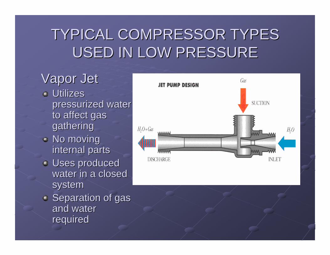
Vapor JetVapor JetUtilizes Utilizes pressurized water pressurized water to affect gas to affect gas gatheringgatheringNo moving No moving internal partsinternal partsUses produced Uses produced water in a closed water in a closed systemsystemSeparation of gas Separation of gas and water and water requiredrequired

VAPOR JET VAPOR VAPOR JET VAPOR RECOVERY TECHNOLOGYRECOVERY TECHNOLOGY
PRODUCED WATER
TANK VAPORS
JET PUMP (EDUCTOR)
WATER PUMP
WATER/GAS MIX
SEPARATOR
PRODUCED WATER RETURN
SALES LINE

Vapor Jet Typical Operating Vapor Jet Typical Operating ParametersParameters
Differential pressure equal Differential pressure equal to or less than 40 psig (for to or less than 40 psig (for singlesingle--stage models).stage models).Volume from approximately Volume from approximately 5 MSCFD to 75 MSCFD (for 5 MSCFD to 75 MSCFD (for singlesingle--compressor units).compressor units).Suction Temperature is not Suction Temperature is not an issue.an issue.Gas composition and Gas composition and saturation level is not an saturation level is not an issue.issue.Gas can be sent down the Gas can be sent down the pipeline, or repipeline, or re--injected into injected into the formationthe formation

JET PUMP VAPOR JET PUMP VAPOR RECOVERY RANGESRECOVERY RANGES
Jet Pump Size ( in. ) 1 1/2 2 2 1/2
Operating Medium Pressure ( psig ) 200 200 200
Operating Medium Rate ( gpm ) 45 82 143
Gas Volume Recovered ( Mcfpd ) 25 45 77
Centrifugal Pump Eff. ( % ) 26 42 53
Motor Eff. ( % ) 0.9 0.9 0.9
KW-HR/day 401 453 625
Power Cost ( $/KW-HR ) 0.045 0.045 0.045
Electrical Cost ( $/Mcf ) 0.74 0.45 0.36

Technological Technological AdvancementsAdvancements
Low Pressure Gas Management Low Pressure Gas Management SystemsSystems

Sensing Technology
Pressure sensing achieved with diaphragm actuated mechanical device / set pressures achieved by manually setting counter weights in conjunction with proximity switch

Sensing Technology
High sensitivity electronic transmitters are now commercially viable for low pressure applications

Sensing Technology
These transmitters are highly accurate to extremely minute pressures –and do not require a highly trained technician to calibrate.

Lubrication SystemsLubrication Systems
Advancements in lubrication systems monitoring and control have dramatically increased bearing life

Lubrication SystemsLubrication Systems
Lubrication requirements are precisely monitored and detailed reporting capabilities are easily downloaded into handheld “palm” devices or directly into Excel format.

Control SystemsControl Systems
PLC driven auto PLC driven auto ignition for natural ignition for natural gas drive engines gas drive engines reduce reduce compressor compressor downtime and downtime and pumper pumper requirementsrequirements

Technology Advancements
Control systems Control systems can range from can range from almost almost completely completely manual to manual to incredibly incredibly sophisticatedsophisticated..


Programmable Logics Controllers have dramatically expanded the capability of these packages
Automated restart is now possible on BOTH electric and engine drive units
Technology Advancements

Typical Shutdown indicators include:High Discharge Temperature
High Discharge PressureHigh Liquid Level
Low Suction PressureLube Oil No-Flow
Excessive Vibration
Technology Advancements

Even the most basic PLC can be configured to automatically call the cell phone number of the
correct field personnel based on the specific cause of the
shutdown.
Technology Advancements

Technology Advancements
Remote MonitoringRemote Monitoring
Now commercially available on this size Now commercially available on this size equipmentequipmentAbility to remotely monitor all variables captured Ability to remotely monitor all variables captured by the PLC from an internet link for a couple by the PLC from an internet link for a couple hundred dollars a monthhundred dollars a monthAbility to view actual real time video footage of Ability to view actual real time video footage of the unit if requiredthe unit if required
HYHY--BON ENGINEERING BON ENGINEERING COMPANY, INC.COMPANY, INC.
Setting a New Standard!!Setting a New Standard!!