variable frequency drives - 2.imimg.com · mitsubishi electric automation ... variable frequency...
TRANSCRIPT
Mitsubishi Electric Automation | Variable Frequency Drives 363
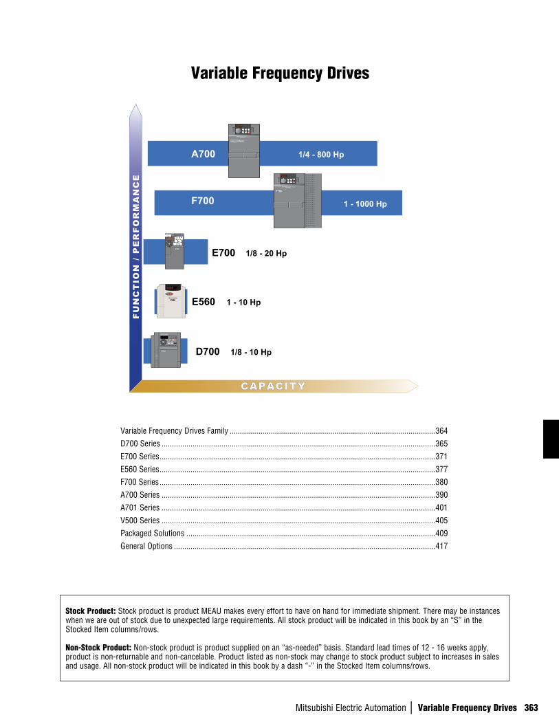
Variable Frequency Drives
Stock Product: Stock product is product MEAU makes every effort to have on hand for immediate shipment. There may be instances when we are out of stock due to unexpected large requirements. All stock product will be indicated in this book by an “S” in the Stocked Item columns/rows.
Non-Stock Product: Non-stock product is product supplied on an “as-needed” basis. Standard lead times of 12 - 16 weeks apply, product is non-returnable and non-cancelable. Product listed as non-stock may change to stock product subject to increases in sales and usage. All non-stock product will be indicated in this book by a dash “-” in the Stocked Item columns/rows.
F700
FU
NC
TIO
N /
PE
RF
OR
MA
NC
E
CAPACITY
A700
E700
D700
1/4 - 800 Hp
1 - 1000 Hp
1/8 - 20 Hp
1/8 - 10 Hp
E560 1 - 10 Hp
A700
F700
E700
RUNSTOP
RESET
E500
D700
MODE SET PUEXT
RUN STOPRESET
Variable Frequency Drives Family ....................................................................................................364
D700 Series .....................................................................................................................................365
E700 Series ......................................................................................................................................371
E560 Series ......................................................................................................................................377
F700 Series ......................................................................................................................................380
A700 Series .....................................................................................................................................390
A701 Series .....................................................................................................................................401
V500 Series .....................................................................................................................................405
Packaged Solutions .........................................................................................................................409
General Options ...............................................................................................................................417
Variable Frequency Drives
364
n V
ARIA
BLE
FREQ
UENC
Y DR
IVES
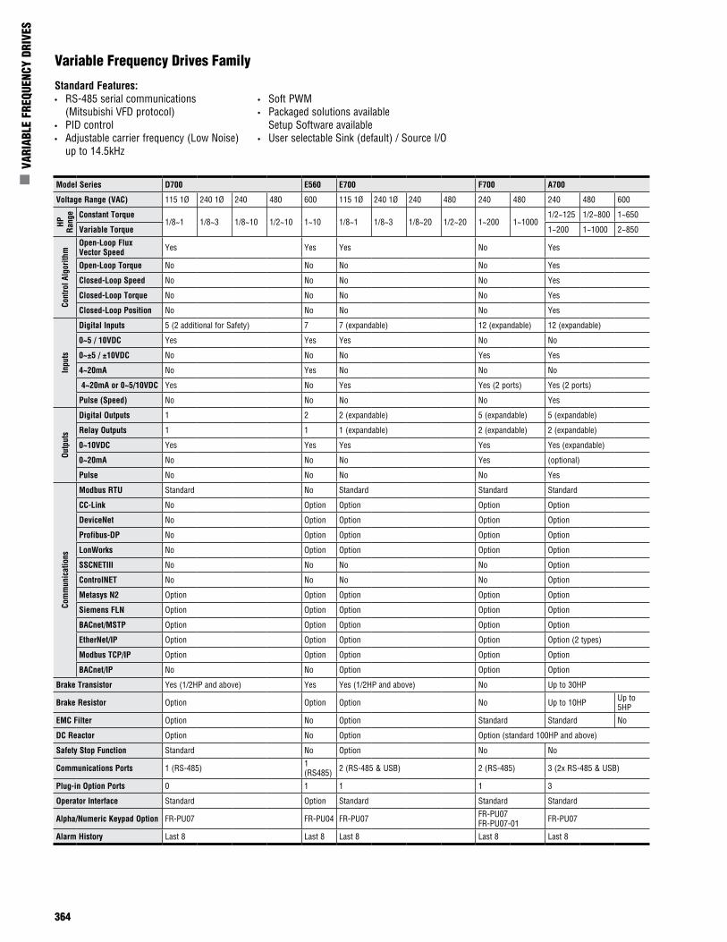
Variable Frequency Drives Family
Standard Features:• RS-485 serial communications
(Mitsubishi VFD protocol) • PID control• Adjustable carrier frequency (Low Noise)
up to 14.5kHz
• Soft PWM• Packaged solutions available
Setup Software available• User selectable Sink (default) / Source I/O
Model Series D700 E560 E700 F700 A700
Voltage Range (VAC) 115 1Ø 240 1Ø 240 480 600 115 1Ø 240 1Ø 240 480 240 480 240 480 600
HP
Rang
e Constant Torque1/8~1 1/8~3 1/8~10 1/2~10 1~10 1/8~1 1/8~3 1/8~20 1/2~20 1~200 1~1000
1/2~125 1/2~800 1~650
Variable Torque 1~200 1~1000 2~850
Cont
rol A
lgor
ithm
Open-Loop Flux Vector Speed Yes Yes Yes No Yes
Open-Loop Torque No No No No Yes
Closed-Loop Speed No No No No Yes
Closed-Loop Torque No No No No Yes
Closed-Loop Position No No No No Yes
Inpu
ts
Digital Inputs 5 (2 additional for Safety) 7 7 (expandable) 12 (expandable) 12 (expandable)
0~5 / 10VDC Yes Yes Yes No No
0~±5 / ±10VDC No No No Yes Yes
4~20mA No Yes No No No
4~20mA or 0~5/10VDC Yes No Yes Yes (2 ports) Yes (2 ports)
Pulse (Speed) No No No No Yes
Outp
uts
Digital Outputs 1 2 2 (expandable) 5 (expandable) 5 (expandable)
Relay Outputs 1 1 1 (expandable) 2 (expandable) 2 (expandable)
0~10VDC Yes Yes Yes Yes Yes (expandable)
0~20mA No No No Yes (optional)
Pulse No No No No Yes
Com
mun
icat
ions
Modbus RTU Standard No Standard Standard Standard
CC-Link No Option Option Option Option
DeviceNet No Option Option Option Option
Profibus-DP No Option Option Option Option
LonWorks No Option Option Option Option
SSCNETIII No No No No Option
ControlNET No No No No Option
Metasys N2 Option Option Option Option Option
Siemens FLN Option Option Option Option Option
BACnet/MSTP Option Option Option Option Option
EtherNet/IP Option Option Option Option Option (2 types)
Modbus TCP/IP Option Option Option Option Option
BACnet/IP No No Option Option Option
Brake Transistor Yes (1/2HP and above) Yes Yes (1/2HP and above) No Up to 30HP
Brake Resistor Option Option Option No Up to 10HP Up to 5HP
EMC Filter Option No Option Standard Standard No
DC Reactor Option No Option Option (standard 100HP and above)
Safety Stop Function Standard No Option No No
Communications Ports 1 (RS-485) 1 (RS485) 2 (RS-485 & USB) 2 (RS-485) 3 (2x RS-485 & USB)
Plug-in Option Ports 0 1 1 1 3
Operator Interface Standard Option Standard Standard Standard
Alpha/Numeric Keypad Option FR-PU07 FR-PU04 FR-PU07 FR-PU07 FR-PU07-01 FR-PU07
Alarm History Last 8 Last 8 Last 8 Last 8 Last 8
Mitsubishi Electric Automation | Variable Frequency Drives 365
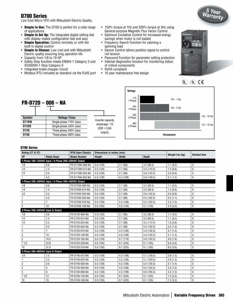
• Simple to Use: The D700 is perfect for a wide range of applications
• Simple to Set Up: The integrated digital setting dial with display makes configuration fast and easy
• Simple Operation: Control remotely or with the built-in digital control
• Simple to Choose: Low cost and with Mitsubishi Electric quality ensuring long operation life
• Capacity from 1/8 to 10 HP• Safety Stop function meets EN954-1 Category 3 and
IEC60204-1 Stop Category 0• Integrated brake chopper circuit• Modbus RTU included as standard via the RJ45 port
• 150% torque at 1Hz and 200% torque at 3Hz using General-purpose Magnetic Flux Vector Control
• Optimum Excitation Control for increased energy savings when motor is not loaded
• Frequency Search Function for catching a spinning load
• Dancer Control allows position signal to control roll tension
• Password Function for parameter setting protection• Internal diagnostics function for monitoring status
of critical components• RoHS compliant• 10 year maintenance free design
D700 Series
D700 SeriesLow Cost Micro VFD with Mitsubishi Electric Quality.
Rating (CT & VT) IP20 Open Chassis Dimensions in inches (mm)Weight Lbs (kg) Stocked Item
HP Rated Amps Model Number Height Width Depth1-Phase 100~120VAC Input / 3-Phase 200~240VAC Output1/8 0.8 FR-D710W-008-NA 5.0 (128) 2.7 (68) 3.2 (80.5) 1.1 (0.5) S1/4 1.4 FR-D710W-014-NA 5.0 (128) 2.7 (68) 4.4 (110.5) 1.3 (0.6) S1/2 2.5 FR-D710W-025-NA 5.0 (128) 2.7 (68) 5.6 (142.5) 2.0 (0.9) S1 4.2 FR-D710W-042-NA 5.0 (128) 4.3 (108) 5.9 (149.5) 3.1 (1.4) S1-Phase 200~240VAC Input / 3-Phase 200~240VAC Output1/8 0.8 FR-D720S-008-NA 5.0 (128) 2.7 (68) 3.2 (80.5) 1.1 (0.5) S1/4 1.4 FR-D720S-014-NA 5.0 (128) 2.7 (68) 3.2 (80.5) 1.3 (0.6) S1/2 2.5 FR-D720S-025-NA 5.0 (128) 2.7 (68) 5.6 (142.5) 2.0 (0.9) S1 4.2 FR-D720S-042-NA 5.0 (128) 2.7 (68) 6.5 (162.5) 2.5 (1.1) S2 7 FR-D720S-070-NA 5.0 (128) 4.3 (108) 6.2 (155.5) 3.3 (1.5) S3 10 FR-D720S-100-NA 5.9 (150) 5.5 (140) 5.7 (145) 4.4 (2.0) S3-Phase 200~240VAC Input & Output1/8 0.8 FR-D720-008-NA 5.0 (128) 2.7 (68) 3.2 (80.5) 1.1 (0.5) S1/4 1.4 FR-D720-014-NA 5.0 (128) 2.7 (68) 3.2 (80.5) 1.1 (0.5) S1/2 2.5 FR-D720-025-NA 5.0 (128) 2.7 (68) 4.5 (112.5) 1.8 (0.8) S1 4.2 FR-D720-042-NA 5.0 (128) 2.7 (68) 5.3 (132.5) 2.2 (1.0) S2 7 FR-D720-070-NA 5.0 (128) 4.3 (108) 5.4 (135.5) 3.1 (1.4) S3 10 FR-D720-100-NA 5.0 (128) 4.3 (108) 5.4 (135.5) 3.1 (1.4) S5 16.5 FR-D720-165-NA 5.0 (128) 6.7 (170) 5.6 (142.5) 4.0 (1.8) S7 1/2 23.8 FR-D720-238-NA 5.9 (150) 8.7 (220) 6.1 (155) 8.0 (3.6) S10 31.8 FR-D720-318-NA 5.9 (150) 8.7 (220) 6.1 (155) 8.0 (3.6) S3-Phase 380~480VAC Input & Output1/2 1.2 FR-D740-012-NA 5.0 (128) 4.3 (108) 5.1 (129.5) 2.9 (1.3) S1 2.2 FR-D740-022-NA 5.0 (128) 4.3 (108) 5.1 (129.5) 2.9 (1.3) S2 3.6 FR-D740-036-NA 5.0 (128) 4.3 (108) 5.4 (135.5) 3.1 (1.4) S3 5 FR-D740-050-NA 5.0 (128) 4.3 (108) 6.2 (155.5) 3.3 (1.5) S5 8 FR-D740-080-NA 5.0 (128) 4.3 (108) 6.6 (165.5) 3.3 (1.5) S7 1/2 12 FR-D740-120-NA 5.9 (150) 8.7 (220) 6.1 (155) 7.3 (3.3) S10 16 FR-D740-160-NA 5.9 (150) 8.7 (220) 6.1 (155) 7.3 (3.3) S
Symbol Voltage ClassD710W Single-phase 115V classD720S Single-phase 240V classD720 Three-phase 240V classD740 Three-phase 480V class
FR-D720 – 008 – NA
Inverter capacityamperage / 10
(008 = 0.8A output)
Voltage
1151 Phase 1/8 – 1 Hp
2401 Phase 1/8 – 3 Hp
240 3 Phase 1/8 – 10 Hp
480 3 Phase 1/2 – 10 Hp
Horsepower
366
n V
ARIA
BLE
FREQ
UENC
Y DR
IVES
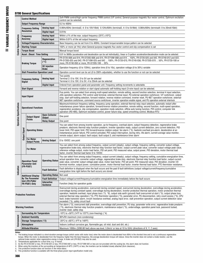
D700 General SpecificationsCo
ntro
l Spe
cific
atio
nsControl Method Soft-PWM control/high carrier frequency PWM control (V/F control, General-purpose magnetic flux vector control, Optimum excitation
control can be selected)Output Frequency Range 0.2 to 400Hz
Frequency Setting Resolution
Analog Input 0.06Hz/60Hz (terminal2, 4: 0 to 10V/10bit) 0.12Hz/60Hz (terminal2, 4: 0 to 5V/9bit) 0.06Hz/60Hz (terminal4: 0 to 20mA/10bit)
Digital Input 0.01Hz
Frequency Accuracy
Analog Input Within ±1% of the max. output frequency (25°C ±10°C)
Digital Input Within 0.01% of the set output frequency
Voltage/Frequency Characteristics Base frequency can be set from 0 to 400Hz. Constant torque/variable torque pattern can be selected
Starting Torque 150% or more (at 1Hz) when General-purpose magnetic flux vector control and slip compensation is set
Torque Boost Manual torque boost
Accel. /Decel. Time Setting 0.01 to 3600s (acceleration and deceleration can be set individually), linear or S-pattern acceleration/deceleration mode can be selected.
Braking Torque
Regeneration (*1)
FR-D720-008 and 014, FR-D720S-008 and 014, FR-D710W-008 and 014 ... 150%, FR-D720-025 and 042, FR-D740-012 and 022, FR-D720S-025 and 042, FR-D710W-025 and 042 ... 100%, FR-D720-070, FR-D740-036, FR-D720S-070 ... 50%, FR-D720-100 or more, FR-D740-050 or more, FR-D720S-100 ... 20%
DC Injection Brake Operation frequency (0 to 120Hz), operation time (0 to 10s), operation voltage (0 to 30%) variable
Stall Prevention Operation Level Operation current level can be set (0 to 200% adjustable), whether to use the function or not can be selected
Oper
atio
n Sp
ecifi
catio
ns
Frequency Setting Signal
Analog InputTwo pointsTerminal 2: 0 to 10V, 0 to 5V can be selectedTerminal 4: 0 to 10V, 0 to 5V, 4 to 20mA can be selected
Digital Input Entered from operation panel and parameter unit. Frequency setting increments is selectable.
Start Signal Forward and reverse rotation or start signal automatic self-holding input (3-wire input) can be selected.
Input Signal
Five points. You can select from among multi-speed selection, remote setting, second function selection, terminal 4 input selection, JOG operation selection, PID control valid terminal, external thermal input, PU-external operation switchover, V/F switchover, output stop, start self-holding selection, forward rotation, reverse rotation command, inverter reset, PU-NET operation switchover, external-NET operation switchover, command source switchover, inverter operation enable signal, and PU operation external interlock
Operational Functions
Maximum/minimum frequency setting, frequency jump operation, external thermal relay input selection, automatic restart after instantaneous power failure operation, forward/reverse rotation prevention, remote setting, second function, multi-speed operation, regeneration avoidance, slip compensation, operation mode selection, offline auto tuning function, PID control, computer link operation (RS-485), Optimum excitation control, power failure stop, speed smoothing control, Modbus-RTU
Outp
ut S
igna
l
Output Signal Points
Open Collector Output One point
Relay Output One point
Operating Status
You can select from among inverter operation, up-to-frequency, overload alarm, output frequency detection, regenerative brake prealarm, electronic thermal relay function prealarm, inverter operation ready, output current detection, zero current detection, PID lower limit, PID upper limit, PID forward/reverse rotation output, fan alarm (*3), heatsink overheat pre-alarm, deceleration at an instantaneous power failure, PID control activated, PID output interruption, during retry, life alarm, current average value monitor, remote output, alarm output, fault output, fault output 3, and maintenance timer alarm
For Meter Output Points Analog Output 0 to 10VDC: one point
For Meter
You can select from among output frequency, output current (steady), output voltage, frequency setting, converter output voltage, regenerative brake duty, electronic thermal relay function load factor, output current peak value, converter output voltage peak value, reference voltage output, motor load factor, PID set point, PID measured value, output power, PID deviation, motor thermal load factor, inverter thermal load factor 0 to 10VDC
Indi
catio
n
Operation Panel Parameter Unit (FR-PU07)
Operating Status
You can select from among output frequency, output current (steady), output voltage, frequency setting, cumulative energization time, actual operation time, converter output voltage, regenerative brake duty, electronic thermal relay function load factor, output current peak value, converter output voltage peak value, motor load factor, PID set point, PID measured value, PID deviation, inverter I/O terminal monitor, output power, cumulative power, motor thermal load factor, inverter thermal load factor, PTC thermistor resistance.
Fault Definition Fault definition is displayed when the fault occurs and the past 8 fault definitions (output voltage/current/frequency/cumulative energization time right before the fault occurs) are stored
Additional Display By The Parameter Unit (FR-PU04/FR-PU07) Only
Operating Status Not used
Fault Definition Output voltage/current/frequency/cumulative energization time immediately before the fault occursInteractive Guidance Function (help) for operation guide
Protective Functions
Overcurrent during acceleration, overcurrent during constant speed, overcurrent during deceleration, overvoltage during acceleration, overvoltage during constant speed, overvoltage during deceleration, inverter protection thermal operation, motor protection thermal operation, heatsink overheat, input phase loss (*5, *6), output side earth (ground) fault overcurrent at start (*5), output phase loss, external thermal relay operation (*5), PTC thermistor operation (*5), parameter error, PU disconnection, retry count excess (*5), CPU fault, brake transistor alarm, inrush resistance overheat, analog input error, stall prevention operation, output current detection value exceeded (*5), safety circuit fault
Warning FunctionsFan alarm (*3), overcurrent stall prevention, overvoltage stall prevention, PU stop, parameter write error, regenerative brake prealarm (*5), electronic thermal relay function prealarm, maintenance output (*5), undervoltage, operation panel lock, password locked, inverter reset, safety stop
Envi
ronm
ent Surrounding Air Temperature -10°C to +50°C (14°F to 122°F) (non-freezing) (*4)
Ambient Humidity 90%RH maximum (non-condensing)
Storage Temperature (*2) -20°C to +65°C (-4°F to 149°F)
Atmosphere Indoors (without corrosive gas, flammable gas, oil mist, dust and dirt, etc.)
Altitude/Vibration Maximum 1000m (3280.80 feet) above sea level, 5.9m/s2 or less at 10 to 55Hz (directions of X, Y, Z axes)
Notes:1. The braking torque indicated is a short-duration average torque (which varies with motor loss) when the motor alone is decelerated from 60Hz in the shortest time and is not a continuous regenerative
torque. When the motor is decelerated from the frequency higher than the base frequency, the average deceleration torque will reduce. Since the inverter does not contain a brake resistor, use the optional brake resistor when regenerative energy is large. A brake unit (FR-BU2) may also be used.
2. Temperatures applicable for a short time, e.g. in transit.3. As the FR-D720-042 or less, FR-D740-022 or less, FR-D720S-042 or less, FR-D710W-042 or less are not provided with the cooling fan, this alarm does not function.4. When using the inverters at the surrounding air temperature of 40°C (104°F) or less, the inverters can be installed closely attached (0cm clearance).5. This protective function does not function in the initial status.6. This protective function is available with the three-phase power input specification model only.
Mitsubishi Electric Automation | Variable Frequency Drives 367
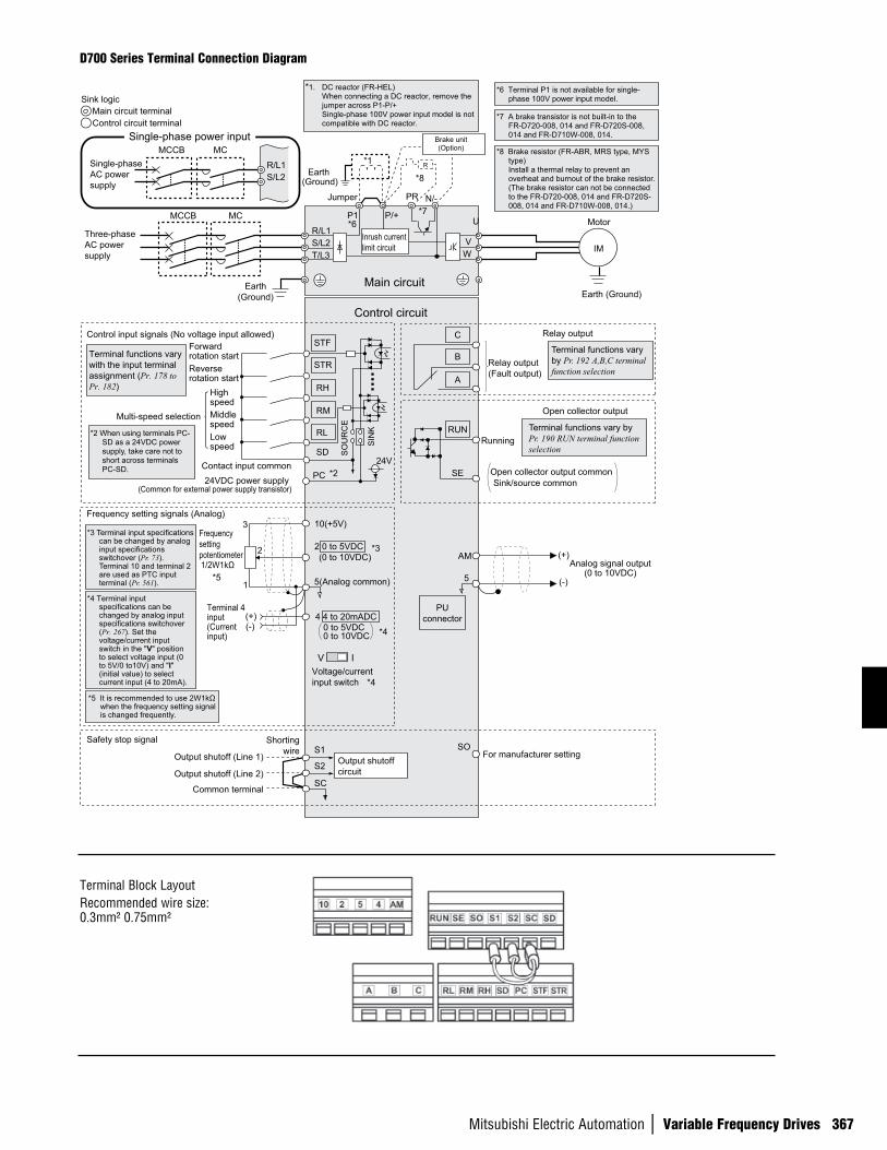
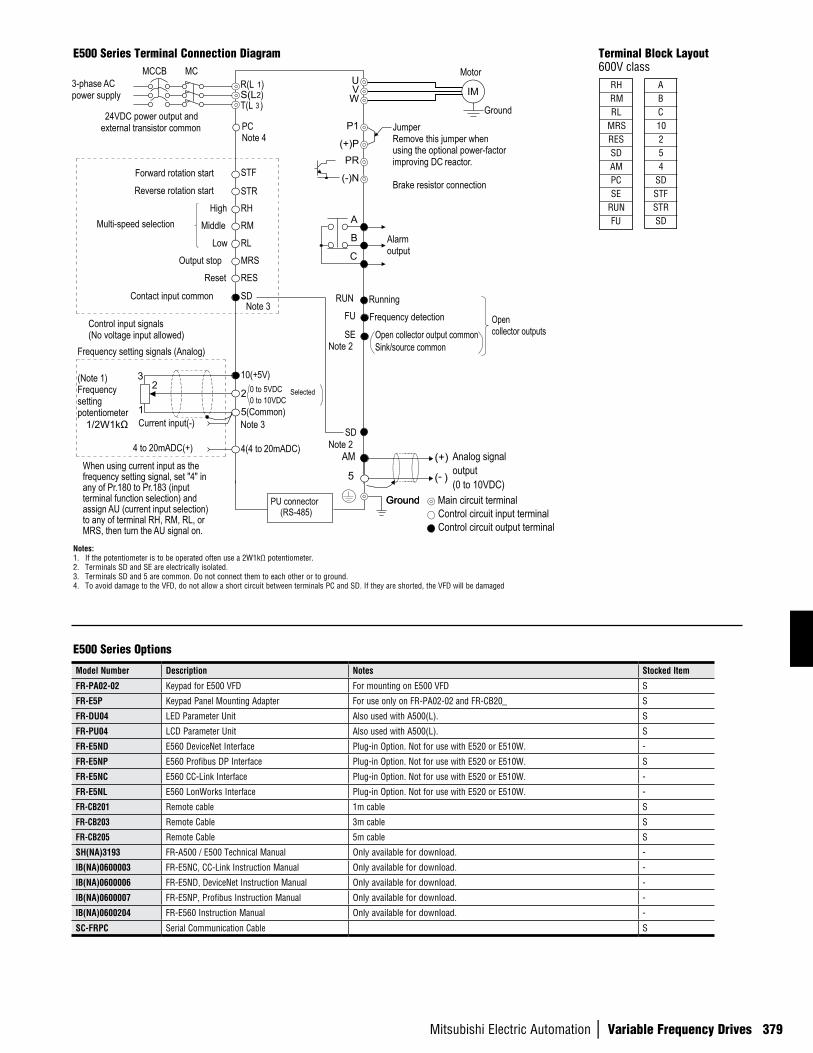
D700 Series Terminal Connection Diagram
Earth(Ground)
Motor
IM
Earth (Ground)
Three-phaseAC power supply
MCCB MC
R/L1
P1 P/+
PR N/-
S/L2T/L3
U
VW
Earth(Ground)
*8 Brake resistor (FR-ABR, MRS type, MYS type)Install a thermal relay to prevent an overheat and burnout of the brake resistor. (The brake resistor can not be connected to the FR-D720-008, 014 and FR-D720S-008, 014 and FR-D710W-008, 014.)
Forwardrotation start
Reverserotation start
Middlespeed
Highspeed
Lowspeed
Control input signals (No voltage input allowed)
24VDC power supply (Common for external power supply transistor)
Contact input common
STR
STF
RH
RM
RL
SD
PC
Relay output
Running
Open collector output
Open collector output commonSink/source common
RUN
SE
A
B
C
Frequency setting signals (Analog)
2 0 to 5VDC
10(+5V)
2
3
1
4 4 to 20mADC
Frequencysettingpotentiometer1/2W1kΩ
Terminal 4 input(Currentinput)
(+)(-)
5(Analog common)
*5 It is recommended to use 2W1kΩwhen the frequency setting signal is changed frequently.
*5
*2 When using terminals PC-SD as a 24VDC power supply, take care not to short across terminals PC-SD.
PUconnector
*1. DC reactor (FR-HEL) When connecting a DC reactor, remove the jumper across P1-P/+ Single-phase 100V power input model is not compatible with DC reactor.Control circuit terminal
Main circuit terminalSink logic
Jumper
*1
*8
*7
*2
*3
*4
Terminal functions vary with the input terminal assignment (Pr. 178 to Pr. 182)
Multi-speed selectionTerminal functions vary by Pr. 190 RUN terminal function selection
Terminal functions vary by Pr. 192 A,B,C terminal function selection
SIN
K
SO
UR
CE
V I
*4
0 to 5VDC
(0 to 10VDC)
0 to 10VDC
*4 Terminal input specifications can be changed by analog input specifications switchover (Pr. 267). Set the voltage/current input switch in the "V" position to select voltage input (0 to 5V/0 to10V) and "I"(initial value) to select current input (4 to 20mA).
Voltage/currentinput switch
Main circuit
Control circuit
R
Relay output(Fault output)
Brake unit(Option)
*8 Common terminal of terminal SO is terminal SC. (Connected to terminal SD inside of the inverter.)
*3 Terminal input specifications can be changed by analog input specifications switchover (Pr. 73).Terminal 10 and terminal 2 are used as PTC input terminal (Pr. 561).
Output shutoff (Line 1)
Output shutoff (Line 2)
Common terminal
Safety stop signalS1
S2
SC
Safety monitor output *8SO
Shortingwire
Single-phaseAC power supply
MCCB MC
R/L1S/L2
Single-phase power input
*7 A brake transistor is not built-in to the FR-D720-008, 014 and FR-D720S-008, 014 and FR-D710W-008, 014.
AM
5
(+)
(-)
Analog signal output(0 to 10VDC)
*6
*6 Terminal P1 is not available for single-phase 100V power input model.
Inrush currentlimit circuit
24V
Output shutoff circuit
For manufacturer setting
Terminal Block LayoutRecommended wire size: 0.3mm² 0.75mm²
368
n V
ARIA
BLE
FREQ
UENC
Y DR
IVES
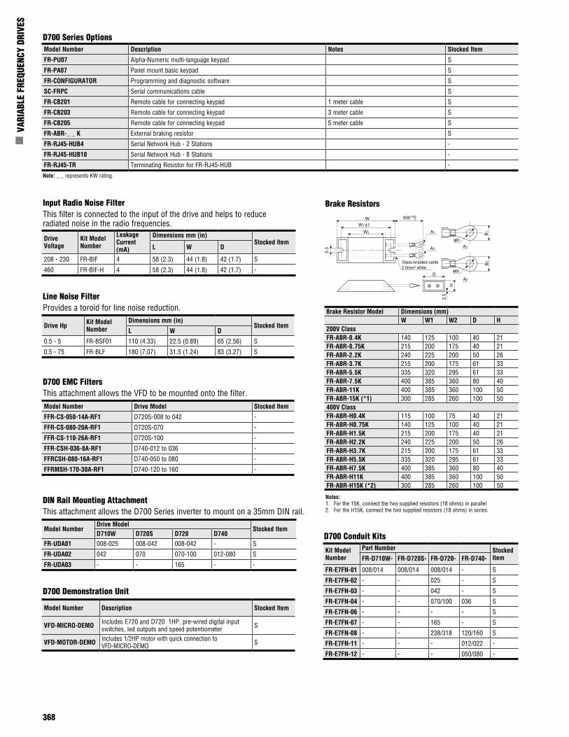
D700 EMC FiltersThis attachment allows the VFD to be mounted onto the filter.
DIN Rail Mounting AttachmentThis attachment allows the D700 Series inverter to mount on a 35mm DIN rail.
Drive Hp Kit Model Number
Dimensions mm (in)Stocked Item
L W D
0.5 - 5 FR-BSF01 110 (4.33) 22.5 (0.89) 65 (2.56) S
0.5 - 75 FR-BLF 180 (7.07) 31.5 (1.24) 83 (3.27) S
Drive Voltage
Kit Model Number
Leakage Current (mA)
Dimensions mm (in)Stocked Item
L W D
208 - 230 FR-BIF 4 58 (2.3) 44 (1.8) 42 (1.7) S
460 FR-BIF-H 4 58 (2.3) 44 (1.8) 42 (1.7) -
Input Radio Noise FilterThis filter is connected to the input of the drive and helps to reduce radiated noise in the radio frequencies.
Line Noise FilterProvides a toroid for line noise reduction.
Model NumberDrive Model
Stocked Item D710W D720S D720 D740
FR-UDA01 008-025 008-042 008-042 - S
FR-UDA02 042 070 070-100 012-080 S
FR-UDA03 - - 165 - -
Brake Resistors
Model Number Description Stocked Item
VFD-MICRO-DEMO Includes E720 and D720 1HP, pre-wired digital input switches, led outputs and speed potentiometer S
VFD-MOTOR-DEMO Includes 1/2HP motor with quick connection to VFD-MICRO-DEMO S
D700 Demonstration Unit
D700 Conduit Kits
Model Number Drive Model Stocked Item
FFR-CS-050-14A-RF1 D720S-008 to 042 -
FFR-CS-080-20A-RF1 D720S-070 -
FFR-CS-110-26A-RF1 D720S-100 -
FFR-CSH-036-8A-RF1 D740-012 to 036 -
FFRCSH-080-16A-RF1 D740-050 to 080 -
FFRMSH-170-30A-RF1 D740-120 to 160 -
Kit Model Number
Part Number Stocked ItemFR-D710W- FR-D720S- FR-D720- FR-D740-
FR-E7FN-01 008/014 008/014 008/014 - S
FR-E7FN-02 - - 025 - S
FR-E7FN-03 - - 042 - S
FR-E7FN-04 - - 070/100 036 S
FR-E7FN-06 - - - - S
FR-E7FN-07 - - 165 - S
FR-E7FN-08 - - 238/318 120/160 S
FR-E7FN-11 - - - 012/022 -
FR-E7FN-12 - - - 050/080 -
D700 Series OptionsModel Number Description Notes Stocked Item
FR-PU07 Alpha-Numeric multi-language keypad S
FR-PA07 Panel mount basic keypad S
FR-CONFIGURATOR Programming and diagnostic software S
SC-FRPC Serial communications cable S
FR-CB201 Remote cable for connecting keypad 1 meter cable S
FR-CB203 Remote cable for connecting keypad 3 meter cable S
FR-CB205 Remote cable for connecting keypad 5 meter cable S
FR-ABR-_ _ K External braking resistor S
FR-RJ45-HUB4 Serial Network Hub - 2 Stations -
FR-RJ45-HUB10 Serial Network Hub - 8 Stations -
FR-RJ45-TR Terminating Resistor for FR-RJ45-HUB -
Note: _ _ represents KW rating.
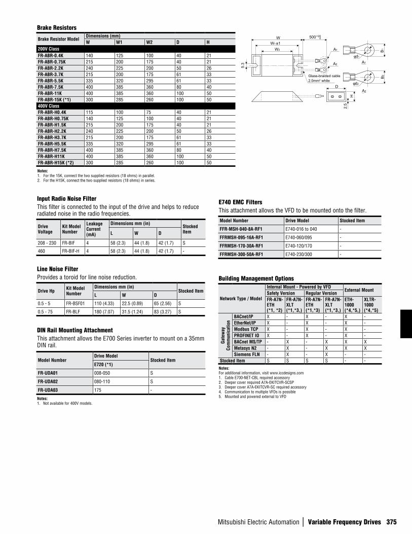
Brake Resistor Model Dimensions (mm)W W1 W2 D H
200V ClassFR-ABR-0.4K 140 125 100 40 21 FR-ABR-0.75K 215 200 175 40 21 FR-ABR-2.2K 240 225 200 50 26 FR-ABR-3.7K 215 200 175 61 33 FR-ABR-5.5K 335 320 295 61 33 FR-ABR-7.5K 400 385 360 80 40 FR-ABR-11K 400 385 360 100 50FR-ABR-15K (*1) 300 285 260 100 50400V ClassFR-ABR-H0.4K 115 100 75 40 21 FR-ABR-H0.75K 140 125 100 40 21 FR-ABR-H1.5K 215 200 175 40 21 FR-ABR-H2.2K 240 225 200 50 26 FR-ABR-H3.7K 215 200 175 61 33 FR-ABR-H5.5K 335 320 295 61 33 FR-ABR-H7.5K 400 385 360 80 40 FR-ABR-H11K 400 385 360 100 50FR-ABR-H15K (*2) 300 285 260 100 50
WW1 ±1
W2
5.3
500+20 0
D
H
2.5
φd1
B1
A1
A1
φd2
B2
A2
A2
Glass-braided cable2.0mm2 white
Notes:1. For the 15K, connect the two supplied resistors (18 ohms) in parallel2. For the H15K, connect the two supplied resistors (18 ohms) in series.
Mitsubishi Electric Automation | Variable Frequency Drives 369
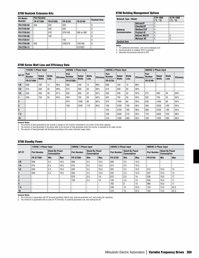
D700 Heatsink Extension Kits
HP-CT
115VAC 1-Phase Input 240VAC 1-Phase Input 240VAC 3-Phase Input 480VAC 3-Phase Input
Part Number Rated
WattsWatts Loss Efficiency
Part Number Rated
WattsWatts Loss Efficiency
Part Number Rated
WattsWatts Loss Efficiency
Part Number Rated
WattsWatts Loss Efficiency
FR-D710W- FR-D720S- FR-D720- FR-D740-
1/8 008 100 14 86% 008 100 14 86% 008 100 14 86% - - - -
1/4 015 200 20 90% 015 200 20 90% 014 200 20 90% - - - -
1/2 030 400 38 91% 030 400 32 92% 025 400 32 92% 012 400 40 90%
1 050 750 50 93% 050 750 50 93% 042 750 50 93% 022 750 55 93%
2 - - - - 070 1500 80 95% 070 1500 80 95% 036 1500 90 94%
3 - - - - 100 2200 110 95% 100 2200 100 95% 050 2200 100 95%
5 - - - - - - - - 165 3700 160 96% 080- 3700 180 95%
7.5 - - - - - - - - 238 5500 270 95% 120 5500 240 96%
10 - - - -- - - - - 318 7500 360 95% 160 7500 280 96%
General Notes:1. The amount of heat generated by the inverter is based on one inverter connected to one motor of the same capacity.2. The amount of heat generated in the above table is the amount of heat generated when the inverter is operated at its rated current.3. The amount of heat generated will decrease according to the motor load and usage (duty).
D700 Series Watt Loss and Efficiency Data
Kit Model Number
Part NumberStocked Item
FR-D710W- FR-D720S- FR-D720- FR-D740-
FR-E7CN-02 025 025 025 - S
FR-E7CN-03 - 042 042 - S
FR-E7CN-04 - 070 070/100 036 to 080 S
FR-E7CN-06 - 100 - - S
FR-E7CN-07 - - 165 - S
FR-E7CN-08 042 - 238/318 120/160 S
FR-E7CN-11 - - - 012/022 -
HP-CT
115VAC 1-Phase Input 240VAC 1-Phase Input 240VAC 3-Phase Input 480VAC 3-Phase Input
Part Number Stand-By Power Consumption Part Number Stand-By Power
Consumption Part Number Stand-By Power Consumption Part Number Stand-By Power
Consumption
FR-D710W- Min Max FR-D720S- Min Max FR-D720- Min Max FR-D740- Min Max
1/8 008 5.5 10.5 008 5.5 10.5 008 5.5 10.5 - - -
1/4 015 5.5 10.5 015 5.5 10.5 014 5.5 10.5 - - -
1/2 030 5.5 10.5 030 5.5 10.5 025 5.5 10.5 012 10.5 15
1 050 5.5 10.5 050 5.5 10.5 042 5.5 10.5 022 10.5 15
2 - - - 070 5.5 14 070 5.5 14 036 10.5 173 - - - 100 5.5 14 100 5.5 14 050 10.5 175 - - - - - - 165 6 15 080 10.5 177.5 - - - - - - 238 13 22.5 120 13.5 22.5
10 - - - - - - 318 13 22.5 160 13.5 22.5
General Notes:1. The maximum is generated with PC terminal operating 100mA load, external parameter unit, and cooling fan operating.2. The minimum is generated with no load on PC terminal, no external parameter unit, and cooling fan off.
D700 Standby Power
Notes:1. For additional information, visit www.iccdesigns.com2. Communication to multiple VFD’s is possible3. Mounted and powered external to VFD
D700 Building Management Options
Network Type / Model ETH-1000 (*2, *3)
XLTR-1000 (*2, *3)
Gateway Communication
BACnet/IP X -EtherNet/IP X -Modbus/TCP X -Profinet IO X -BACnet MS/TP X XMetasys N2 X X
Stocked Item - -
370
n V
ARIA
BLE
FREQ
UENC
Y DR
IVES
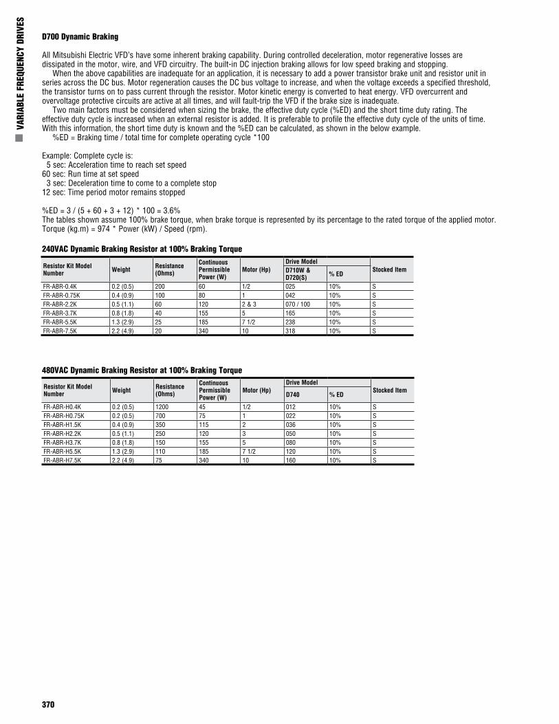
D700 Dynamic Braking
All Mitsubishi Electric VFD’s have some inherent braking capability. During controlled deceleration, motor regenerative losses are dissipated in the motor, wire, and VFD circuitry. The built-in DC injection braking allows for low speed braking and stopping. When the above capabilities are inadequate for an application, it is necessary to add a power transistor brake unit and resistor unit in series across the DC bus. Motor regeneration causes the DC bus voltage to increase, and when the voltage exceeds a specified threshold, the transistor turns on to pass current through the resistor. Motor kinetic energy is converted to heat energy. VFD overcurrent and overvoltage protective circuits are active at all times, and will fault-trip the VFD if the brake size is inadequate. Two main factors must be considered when sizing the brake, the effective duty cycle (%ED) and the short time duty rating. The effective duty cycle is increased when an external resistor is added. It is preferable to profile the effective duty cycle of the units of time. With this information, the short time duty is known and the %ED can be calculated, as shown in the below example. %ED = Braking time / total time for complete operating cycle *100
Example: Complete cycle is: 5 sec: Acceleration time to reach set speed60 sec: Run time at set speed 3 sec: Deceleration time to come to a complete stop12 sec: Time period motor remains stopped
%ED = 3 / (5 + 60 + 3 + 12) * 100 = 3.6%The tables shown assume 100% brake torque, when brake torque is represented by its percentage to the rated torque of the applied motor.Torque (kg.m) = 974 * Power (kW) / Speed (rpm).
Resistor Kit Model Number Weight Resistance
(Ohms)
Continuous Permissible Power (W)
Motor (Hp)Drive Model
Stocked ItemD710W &D720(S) % ED
FR-ABR-0.4K 0.2 (0.5) 200 60 1/2 025 10% SFR-ABR-0.75K 0.4 (0.9) 100 80 1 042 10% SFR-ABR-2.2K 0.5 (1.1) 60 120 2 & 3 070 / 100 10% SFR-ABR-3.7K 0.8 (1.8) 40 155 5 165 10% SFR-ABR-5.5K 1.3 (2.9) 25 185 7 1/2 238 10% SFR-ABR-7.5K 2.2 (4.9) 20 340 10 318 10% S
240VAC Dynamic Braking Resistor at 100% Braking Torque
480VAC Dynamic Braking Resistor at 100% Braking Torque
Resistor Kit Model Number Weight Resistance
(Ohms)
Continuous Permissible Power (W)
Motor (Hp)Drive Model
Stocked ItemD740 % ED
FR-ABR-H0.4K 0.2 (0.5) 1200 45 1/2 012 10% SFR-ABR-H0.75K 0.2 (0.5) 700 75 1 022 10% SFR-ABR-H1.5K 0.4 (0.9) 350 115 2 036 10% SFR-ABR-H2.2K 0.5 (1.1) 250 120 3 050 10% SFR-ABR-H3.7K 0.8 (1.8) 150 155 5 080 10% SFR-ABR-H5.5K 1.3 (2.9) 110 185 7 1/2 120 10% SFR-ABR-H7.5K 2.2 (4.9) 75 340 10 160 10% S
Mitsubishi Electric Automation | Variable Frequency Drives 371
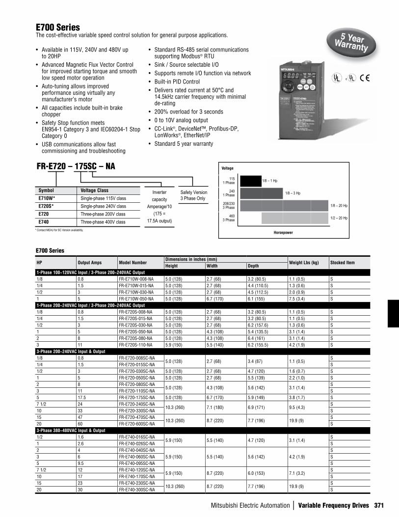
E700 SeriesThe cost-effective variable speed control solution for general purpose applications.
• Available in 115V, 240V and 480V up to 20HP
• Advanced Magnetic Flux Vector Control for improved starting torque and smooth low speed motor operation
• Auto-tuning allows improved performance using virtually any manufacturer’s motor
• All capacities include built-in brake chopper
• Safety Stop function meets EN954-1 Category 3 and IEC60204-1 Stop Category 0
• USB communications allow fast commissioning and troubleshooting
• Standard RS-485 serial communications supporting Modbus® RTU
• Sink / Source selectable I/O• Supports remote I/O function via network• Built-in PID Control• Delivers rated current at 50°C and
14.5kHz carrier frequency with minimal de-rating
• 200% overload for 3 seconds• 0 to 10V analog output• CC-Link®, DeviceNet™, Profibus-DP,
LonWorks®, EtherNet/IP• Standard 5 year warranty
E700 Series
HP Output Amps Model NumberDimensions in inches (mm)
Weight Lbs (kg) Stocked ItemHeight Width Depth
1-Phase 100~120VAC Input / 3-Phase 200~240VAC Output1/8 0.8 FR-E710W-008-NA 5.0 (128) 2.7 (68) 3.2 (80.5) 1.1 (0.5) S1/4 1.5 FR-E710W-015-NA 5.0 (128) 2.7 (68) 4.4 (110.5) 1.3 (0.6) S1/2 3 FR-E710W-030-NA 5.0 (128) 2.7 (68) 4.5 (112.5) 2.0 (0.9) S1 5 FR-E710W-050-NA 5.0 (128) 6.7 (170) 6.1 (155) 7.5 (3.4) S1-Phase 200~240VAC Input / 3-Phase 200~240VAC Output1/8 0.8 FR-E720S-008-NA 5.0 (128) 2.7 (68) 3.2 (80.5) 1.1 (0.5) S1/4 1.5 FR-E720S-015-NA 5.0 (128) 2.7 (68) 3.2 (80.5) 1.1 (0.5) S1/2 3 FR-E720S-030-NA 5.0 (128) 2.7 (68) 6.2 (157.6) 1.3 (0.6) S1 5 FR-E720S-050-NA 5.0 (128) 4.3 (108) 5.4 (135.5) 3.1 (1.4) S2 8 FR-E720S-080-NA 5.0 (128) 4.3 (108) 6.4 (161) 3.1 (1.4) S3 11 FR-E720S-110-NA 5.9 (150) 5.5 (140) 6.2 (155.5) 4.2 (1.9) S3-Phase 200~240VAC Input & Output1/8 0.8 FR-E720-008SC-NA
5.0 (128) 2.7 (68) 3.4 (87) 1.1 (0.5)S
1/4 1.5 FR-E720-015SC-NA S1/2 3 FR-E720-030SC-NA 5.0 (128) 2.7 (68) 4.7 (120) 1.6 (0.7) S1 5 FR-E720-050SC-NA 5.0 (128) 2.7 (68) 5.5 (139) 2.2 (1.0) S2 8 FR-E720-080SC-NA
5.0 (128) 4.3 (108) 5.6 (142) 3.1 (1.4)S
3 11 FR-E720-110SC-NA S5 17.5 FR-E720-175SC-NA 5.0 (128) 6.7 (170) 5.9 (149) 3.8 (1.7) S7 1/2 24 FR-E720-240SC-NA
10.3 (260) 7.1 (180) 6.9 (171) 9.5 (4.3)S
10 33 FR-E720-330SC-NA S15 47 FR-E720-470SC-NA
10.3 (260) 8.7 (220) 7.7 (196) 19.9 (9)S
20 60 FR-E720-600SC-NA S3-Phase 380~480VAC Input & Output1/2 1.6 FR-E740-016SC-NA
5.9 (150) 5.5 (140) 4.7 (120) 3.1 (1.4)S
1 2.6 FR-E740-026SC-NA S2 4 FR-E740-040SC-NA
5.9 (150) 5.5 (140) 5.6 (142) 4.2 (1.9)S
3 6 FR-E740-060SC-NA S5 9.5 FR-E740-095SC-NA S7 1/2 12 FR-E740-120SC-NA
5.9 (150) 8.7 (220) 6.0 (153) 7.1 (3.2)S
10 17 FR-E740-170SC-NA S15 23 FR-E740-230SC-NA
10.3 (260) 8.7 (220) 7.7 (196) 19.9 (9)S
20 30 FR-E740-300SC-NA S
Voltage
1151 Phase 1/8 – 1 Hp
2401 Phase 1/8 – 3 Hp
208/230 3 Phase 1/8 – 20 Hp
460 3 Phase 1/2 – 20 Hp
Horsepower
Symbol Voltage Class
E710W* Single-phase 115V classE720S* Single-phase 240V classE720 Three-phase 200V classE740 Three-phase 400V class
FR-E720 – 175SC – NA
Invertercapacity
Amperage/10(175 =
17.5A output)
Safety Version3 Phase Only
* Contact MEAU for SC Version availablitiy.
372
n V
ARIA
BLE
FREQ
UENC
Y DR
IVES
Cont
rol S
peci
ficat
ions
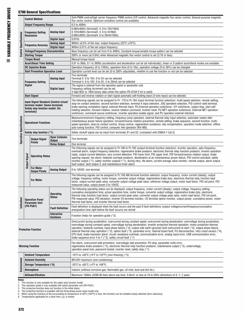
Control Method Soft-PWM control/high carrier frequency PWM control (V/F control, Advanced magnetic flux vector control, General-purpose magnetic flux vector control, Optimum excitation control are available)
Output Frequency Range 0.2 to 400Hz
Frequency Setting Resolution
Analog Input0.06Hz/60Hz (terminal2, 4: 0 to 10V/10bit)0.12Hz/60Hz (terminal2, 4: 0 to 5V/9bit)0.06Hz/60Hz (terminal4: 0 to 20mA/10bit)
Digital Input 0.01Hz
Frequency AccuracyAnalog Input Within ±0.5% of the max. output frequency (25°C ±10°C)Digital Input Within 0.01% of the set output frequency
Voltage/Frequency Characteristics Base frequency can be set from 0 to 400Hz, Constant-torque/variable torque pattern can be selectedStarting Torque 200% or more (at 0.5Hz) when Advanced magnetic flux vector control is set (3.7K or less)Torque Boost Manual torque boostAccel/Decel Time Setting 0.01 to 360s, 0.1 to 3600s (acceleration and deceleration can be set individually), linear or S-pattern accel/decel modes are available.DC Injection Brake Operation frequency (0 to 120Hz), operation time (0 to 10s), operation voltage (0 to 30%) can be changed.Stall Prevention Operation Level Operation current level can be set (0 to 200% adjustable), whether to use the function or not can be selected
Oper
atio
n Sp
ecifi
catio
ns
Frequency Setting Signal
Analog InputTwo terminalsTerminal 2: 0 to 10V, 0 to 5V can be selectedTerminal 4: 0 to 10V, 0 to 5V, 4 to 20mA can be selected
Digital InputThe signal is entered from the operation panel or parameter unit.Frequency setting increment can be set.4 digit BCD or 16bit binary data (when the option FR-A7AX E kit is used)
Start Signal Forward and reverse rotation or start signal automatic self-holding input (3-wire input) can be selected.
Input Signal Standard (Control circuit terminal model: Seven terminals Safety stop function model: Six terminals)
The following signals can be assigned to Pr. 178 to Pr.184 (input terminal function selection): multi-speed selection, remote setting, stop-on contact selection, second function selection, terminal 4 input selection, JOG operation selection, PID control valid terminal, brake opening completion signal, external thermal input, PU-External operation switchover, V/F switchover, output stop, start self-holding selection, forward rotation, reverse rotation command, inverter reset, PU-NET operation switchover, External-NET operation switchover, command source switchover, inverter operation enable signal, and PU operation external interlock
Operational Functions
Maximum/minimum frequency setting, frequency jump operation, external thermal relay input selection, automatic restart after instantaneous power failure operation, forward/reverse rotation prevention, remote setting, brake sequence, second function, multi-speed operation, stop-on contact control, droop control, regeneration avoidance, slip compensation, operation mode selection, offline auto tuning function, PID control, computer link operation (RS-485)
Safety stop function (*1) Safety shutoff signal can be input from terminals S1 and S2. (compliant with EN954-1 Cat.3)
Outp
ut S
igna
l
Output Signal Points
Open Collector Output Two terminals
Relay Output One terminal
Operating Status
The following signals can be assigned to Pr.190 to Pr.192 (output terminal function selection): inverter operation, upto-frequency, overload alarm, output frequency detection, regenerative brake prealarm, electronic thermal relay function prealarm, inverter operation ready, output current detection, zero current detection, PID lower limit, PID upper limit, PID forward/reverse rotation output, brake opening request, fan alarm, heatsink overheat prealarm, deceleration at an instantaneous power failure, PID control activated, safety monitor output (*1), safety monitor output2 (*1), during retry, life alarm, current average value monitor, remote output, alarm output, fault output, fault output 3, and maintenance timer alarm
For Meter Output Points Analog Output 0 to 10VDC: one terminal
For Meter
The following signals can be assigned to Pr.158 AM terminal function selection: output frequency, motor current (steady), output voltage, frequency setting, motor torque, converter output voltage, regenerative brake duty, electronic thermal relay function load factor, output current peak value, converter output voltage peak value, reference voltage output, motor load factor, PID set point, PID measured value, output power 0 to 10VDC
Indi
catio
n
Operation Panel Parameter Unit (FR-PU07)
Operating Status
The following operating status can be displayed: output frequency, motor current (steady), output voltage, frequency setting, cumulative energization time, actual operation time, motor torque, converter output voltage, regenerative brake duty, electronic thermal relay function load factor, output current peak value, converter output voltage peak value, motor load factor, PID set point, PID measured value, PID deviation, inverter I/O terminal monitor, I/O terminal option monitor, output power, cumulative power, motor thermal load factor, and inverter thermal load factor.
Fault Definition Fault definition is displayed when the fault occurs and the past 8 fault definitions (output voltage/current/frequency/cumulative energization time right before the fault occurs) are stored
Interactive Guidance Function (help) for operation guide (*2)
Protective Function
Overcurrent during acceleration, overcurrent during constant speed, overcurrent during deceleration, overvoltage during acceleration, overvoltage during constant speed, overvoltage during deceleration, inverter protection thermal operation, motor protection thermal operation, heatsink overheat, input phase failure (*4), output side earth (ground) fault overcurrent at start (*4), output phase failure, external thermal relay operation (*3), option fault (*3), parameter error, internal board fault, PU disconnection, retry count excess (*4), CPU fault, brake transistor alarm, inrush resistance overheat, communication error, analog input error, USB communication error, brake sequence error 4 to 7 (*3), safety circuit fault (*1)
Warning FunctionFan alarm, overcurrent stall prevention, overvoltage stall prevention, PU stop, parameter write error,regenerative brake prealarm (*3), electronic thermal relay function prealarm, maintenance output (*3), undervoltage,operation panel lock, password locked, inverter reset, safety stop (*1)
Envi
ronm
ent
Ambient Temperature -10°C to +50°C (14°F to 122°F) (non-freezing) (*5)
Ambient Humidity 90%RH maximum (non-condensing)
Storage Temperature (*6) -20°C to +65°C (-4°F to 149°F)
Atmosphere Indoors (without corrosive gas, flammable gas, oil mist, dust and dirt etc.)
Altitude/Vibration Maximum 1000m (3280.80 feet) above sea level, 5.9m/s2 or less at 10 to 55Hz (directions of X, Y, Z axes)
Notes:1. This function is only available for the safety stop function model.2. This operation guide is only available with option parameter unit (FR-PU07).3. This protective function does not function in the initial status.4. This protective function is available with the three-phase power input model only.5. When using the inverters at the surrounding air temperature of 40°C (104°F) or less, the inverters can be installed closely attached (0cm clearance).6. Temperatures applicable for a short time, e.g. in transit.
E700 General Specifications
Mitsubishi Electric Automation | Variable Frequency Drives 373
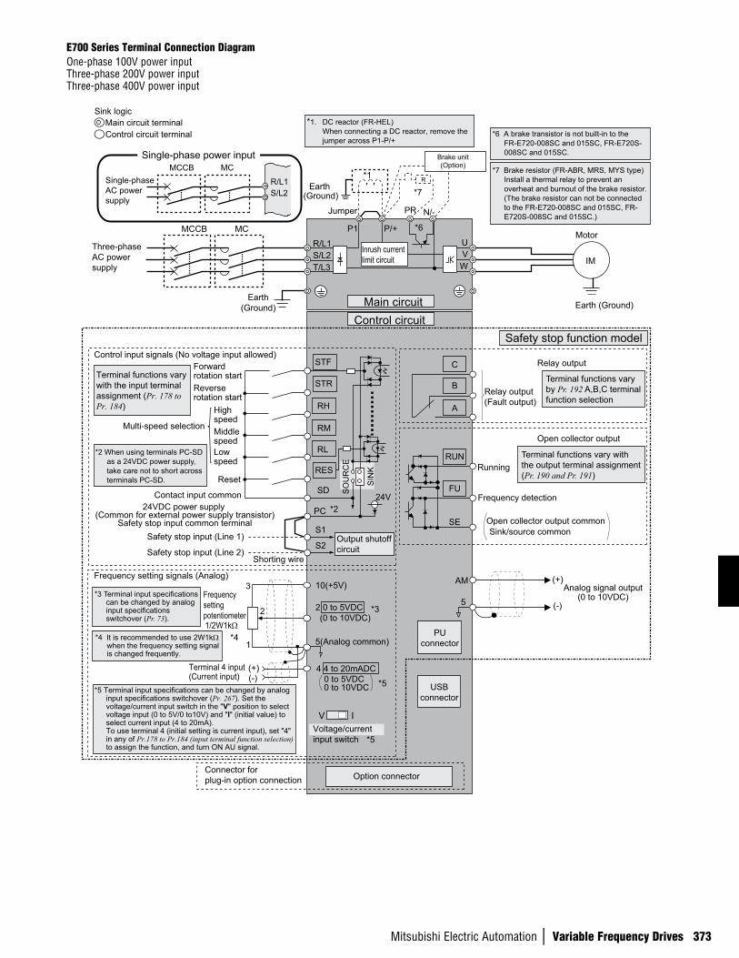
Earth (Ground)
Motor
IM
Earth (Ground)
Three-phase AC power supply
MCCB MC
R/L1
P1 P/+
PR N/-
S/L2T/L3
UVW
Earth(Ground)
*7 Brake resistor (FR-ABR, MRS, MYS type) Install a thermal relay to prevent an overheat and burnout of the brake resistor. (The brake resistor can not be connected to the FR-E720-008SC and 015SC, FR-E720S-008SC and 015SC.)
*6 A brake transistor is not built-in to the FR-E720-008SC and 015SC, FR-E720S-008SC and 015SC.
Forward rotation startReverse rotation start
Middle speed
High speed
Low speed
Reset
Control input signals (No voltage input allowed)
Contact input common24VDC power supply
(Common for external power supply transistor)Safety stop input common terminal
STR
STF
RH
RM
RL
SD
PC
Relay output
Running
Frequency detection
Open collector output
Open collector output commonSink/source common
FU
RUN
SE
A
B
C
AM
5
Frequency setting signals (Analog)
2 0 to 5VDC
10(+5V)
2
3
1
4 4 to 20mADC
Frequency setting potentiometer1/2W1kΩ
Terminal 4 input(Current input)
(+)(-)
5(Analog common)*4 It is recommended to use 2W1kΩ when the frequency setting signal is changed frequently.
*4
Connector for plug-in option connection Option connector
*3 Terminal input specifications can be changed by analog input specifications switchover (Pr. 73).
*2 When using terminals PC-SD as a 24VDC power supply, take care not to short across terminals PC-SD.
PUconnector
USBconnector
Jumper
*1
*7
*6
*2
*3
*5
Terminal functions vary with the input terminal assignment (Pr. 178 to Pr. 184)
Multi-speed selection
Terminal functions vary with the output terminal assignment (Pr. 190 and Pr. 191)
Terminal functions vary by Pr. 192 A,B,C terminal function selection
SIN
K
SO
UR
CE
V I
*5
0 to 5VDC
(0 to 10VDC)
0 to 10VDC
Voltage/current input switch
Main circuitControl circuit
Safety stop function model
R
RES
Relay output(Fault output)
Brake unit(Option)
(+)
(-)
Analog signal output(0 to 10VDC)
Single-phase AC power supply
MCCB MC
R/L1S/L2
Single-phase power input
*1. DC reactor (FR-HEL) When connecting a DC reactor, remove the jumper across P1-P/+
Control circuit terminalMain circuit terminal
Sink logic
*5 Terminal input specifications can be changed by analog input specifications switchover (Pr. 267). Set the voltage/current input switch in the "V" position to select voltage input (0 to 5V/0 to10V) and "I" (initial value) to select current input (4 to 20mA). To use terminal 4 (initial setting is current input), set "4" in any of Pr.178 to Pr.184 (input terminal function selection) to assign the function, and turn ON AU signal.
S1
S2Safety stop input (Line 1)
Shorting wireSafety stop input (Line 2)
24V
Inrush currentlimit circuit
Output shutoff circuit
E700 Series Terminal Connection DiagramOne-phase 100V power input Three-phase 200V power input Three-phase 400V power input
374
n V
ARIA
BLE
FREQ
UENC
Y DR
IVES
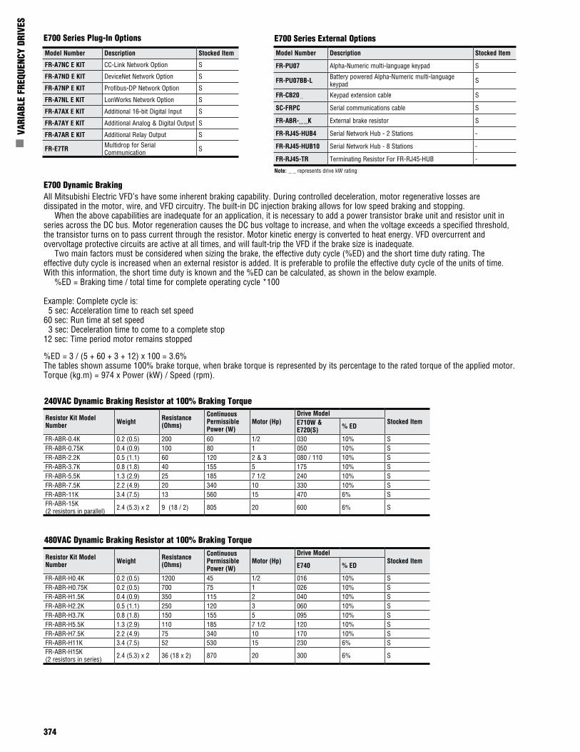
E700 Series Plug-In Options
Model Number Description Stocked Item
FR-PU07 Alpha-Numeric multi-language keypad S
FR-PU07BB-L Battery powered Alpha-Numeric multi-language keypad S
FR-CB20 Keypad extension cable S
SC-FRPC Serial communications cable S
FR-ABR- K External brake resistor S
FR-RJ45-HUB4 Serial Network Hub - 2 Stations -
FR-RJ45-HUB10 Serial Network Hub - 8 Stations -
FR-RJ45-TR Terminating Resistor For FR-RJ45-HUB -
E700 Dynamic BrakingAll Mitsubishi Electric VFD’s have some inherent braking capability. During controlled deceleration, motor regenerative losses are dissipated in the motor, wire, and VFD circuitry. The built-in DC injection braking allows for low speed braking and stopping. When the above capabilities are inadequate for an application, it is necessary to add a power transistor brake unit and resistor unit in series across the DC bus. Motor regeneration causes the DC bus voltage to increase, and when the voltage exceeds a specified threshold, the transistor turns on to pass current through the resistor. Motor kinetic energy is converted to heat energy. VFD overcurrent and overvoltage protective circuits are active at all times, and will fault-trip the VFD if the brake size is inadequate. Two main factors must be considered when sizing the brake, the effective duty cycle (%ED) and the short time duty rating. The effective duty cycle is increased when an external resistor is added. It is preferable to profile the effective duty cycle of the units of time. With this information, the short time duty is known and the %ED can be calculated, as shown in the below example. %ED = Braking time / total time for complete operating cycle *100
Example: Complete cycle is: 5 sec: Acceleration time to reach set speed60 sec: Run time at set speed 3 sec: Deceleration time to come to a complete stop12 sec: Time period motor remains stopped
%ED = 3 / (5 + 60 + 3 + 12) x 100 = 3.6%The tables shown assume 100% brake torque, when brake torque is represented by its percentage to the rated torque of the applied motor.Torque (kg.m) = 974 x Power (kW) / Speed (rpm).
E700 Series External Options
Note: _ _ represents drive kW rating
Model Number Description Stocked Item
FR-A7NC E KIT CC-Link Network Option S
FR-A7ND E KIT DeviceNet Network Option S
FR-A7NP E KIT Profibus-DP Network Option S
FR-A7NL E KIT LonWorks Network Option S
FR-A7AX E KIT Additional 16-bit Digital Input S
FR-A7AY E KIT Additional Analog & Digital Output S
FR-A7AR E KIT Additional Relay Output S
FR-E7TR Multidrop for Serial Communication S
240VAC Dynamic Braking Resistor at 100% Braking Torque
480VAC Dynamic Braking Resistor at 100% Braking Torque
Resistor Kit Model Number Weight Resistance
(Ohms)
Continuous Permissible Power (W)
Motor (Hp)Drive Model
Stocked ItemE710W & E720(S) % ED
FR-ABR-0.4K 0.2 (0.5) 200 60 1/2 030 10% SFR-ABR-0.75K 0.4 (0.9) 100 80 1 050 10% SFR-ABR-2.2K 0.5 (1.1) 60 120 2 & 3 080 / 110 10% SFR-ABR-3.7K 0.8 (1.8) 40 155 5 175 10% SFR-ABR-5.5K 1.3 (2.9) 25 185 7 1/2 240 10% SFR-ABR-7.5K 2.2 (4.9) 20 340 10 330 10% SFR-ABR-11K 3.4 (7.5) 13 560 15 470 6% SFR-ABR-15K (2 resistors in parallel) 2.4 (5.3) x 2 9 (18 / 2) 805 20 600 6% S
Resistor Kit Model Number Weight Resistance
(Ohms)
Continuous Permissible Power (W)
Motor (Hp)Drive Model
Stocked ItemE740 % ED
FR-ABR-H0.4K 0.2 (0.5) 1200 45 1/2 016 10% SFR-ABR-H0.75K 0.2 (0.5) 700 75 1 026 10% SFR-ABR-H1.5K 0.4 (0.9) 350 115 2 040 10% SFR-ABR-H2.2K 0.5 (1.1) 250 120 3 060 10% SFR-ABR-H3.7K 0.8 (1.8) 150 155 5 095 10% SFR-ABR-H5.5K 1.3 (2.9) 110 185 7 1/2 120 10% SFR-ABR-H7.5K 2.2 (4.9) 75 340 10 170 10% SFR-ABR-H11K 3.4 (7.5) 52 530 15 230 6% SFR-ABR-H15K (2 resistors in series) 2.4 (5.3) x 2 36 (18 x 2) 870 20 300 6% S
Mitsubishi Electric Automation | Variable Frequency Drives 375
Drive Hp Kit Model Number
Dimensions mm (in)Stocked Item
L W D
0.5 - 5 FR-BSF01 110 (4.33) 22.5 (0.89) 65 (2.56) S
0.5 - 75 FR-BLF 180 (7.07) 31.5 (1.24) 83 (3.27) S
Drive Voltage
Kit Model Number
Leakage Current (mA)
Dimensions mm (in)Stocked ItemL W D
208 - 230 FR-BIF 4 58 (2.3) 44 (1.8) 42 (1.7) S
460 FR-BIF-H 4 58 (2.3) 44 (1.8) 42 (1.7) -
Model NumberDrive Model
Stocked ItemE720 (*1)
FR-UDA01 008-050 S
FR-UDA02 080-110 S
FR-UDA03 175 -
Brake Resistors
Input Radio Noise FilterThis filter is connected to the input of the drive and helps to reduce radiated noise in the radio frequencies.
Line Noise FilterProvides a toroid for line noise reduction.
E740 EMC FiltersThis attachment allows the VFD to be mounted onto the filter.
Building Management Options
DIN Rail Mounting AttachmentThis attachment allows the E700 Series inverter to mount on a 35mm DIN rail.
Model Number Drive Model Stocked Item
FFR-MSH-040-8A-RF1 E740-016 to 040 -
FFRMSH-095-16A-RF1 E740-060/095 -
FFRMSH-170-30A-RF1 E740-120/170 -
FFRMSH-300-50A-RF1 E740-230/300 -
Brake Resistor ModelDimensions (mm)W W1 W2 D H
200V ClassFR-ABR-0.4K 140 125 100 40 21FR-ABR-0.75K 215 200 175 40 21FR-ABR-2.2K 240 225 200 50 26FR-ABR-3.7K 215 200 175 61 33FR-ABR-5.5K 335 320 295 61 33FR-ABR-7.5K 400 385 360 80 40FR-ABR-11K 400 385 360 100 50FR-ABR-15K (*1) 300 285 260 100 50400V ClassFR-ABR-H0.4K 115 100 75 40 21FR-ABR-H0.75K 140 125 100 40 21FR-ABR-H1.5K 215 200 175 40 21FR-ABR-H2.2K 240 225 200 50 26FR-ABR-H3.7K 215 200 175 61 33FR-ABR-H5.5K 335 320 295 61 33FR-ABR-H7.5K 400 385 360 80 40FR-ABR-H11K 400 385 360 100 50FR-ABR-H15K (*2) 300 285 260 100 50
WW1 ±1
W2
5.3
500+20 0
D
H
2.5
φd1
B1
A1
A1
φd2
B2
A2
A2
Glass-braided cable2.0mm2 white
Notes:For additional information, visit www.iccdesigns.com1. Cable E700-NET-CBL required accessory2. Deeper cover required A7A-EKITCVR-SCSP3. Deeper cover A7A-EKITCVR-SC required accessory4. Communication to multiple VFDs is possible5. Mounted and powered external to VFD
Notes:1. For the 15K, connect the two supplied resistors (18 ohms) in parallel.2. For the H15K, connect the two supplied resistors (18 ohms) in series.
Network Type / Model
Internal Mount - Powered by VFDExternal Mount
Safety Version Regular VersionFR-A7N-ETH (*1, *2)
FR-A7N-XLT (*1,*3,)
FR-A7N-ETH (*1,*3)
FR-A7N-XLT (*1,*3,)
ETH-1000 (*4,*5,)
XLTR-1000 (*4,*5)
Gate
way
Co
mm
unic
atio
n
BACnet/IP X - X - X -EtherNet/IP X - X - X -Modbus TCP X - X - X -PROFINET IO X - X - X -BACnet MS/TP - X - X X XMetasys N2 - X - X X XSiemens FLN - X - X - -
Stocked Item S S S S - -
Notes:1. Not available for 400V models.
376
n V
ARIA
BLE
FREQ
UENC
Y DR
IVES
Model NumberInstallation Model Previous Model
Stocked itemE700 Series E500 Series A0x4 Series Z024 Series
FR-E5T-LE720-030
Direct ReplacementFR-A024-0.4K-UL FR-Z024-0.4K-UL -
E720-050 FR-A024-0.75K-UL - -
General Notes:1. The amount of heat generated by the inverter is based on one inverter connected to one motor of the same capacity.2. The amount of heat generated in the above table is the amount of heat generated when the inverter is operated at its rated current.3. The amount of heat generated will decrease according to the motor load and usage (duty).
Model Number Description Stocked Item
FR-E7FN-01 Conduit kit for E720-008/015 SFR-E7FN-02 Conduit kit for E720-030 SFR-E7FN-03 Conduit kit for E720-050 SFR-E7FN-04 Conduit kit for E720-080/110 SFR-E7FN-05 Conduit kit for E740-016/026 SFR-E7FN-06 Conduit kit for E740-040/060/090 SFR-E7FN-07 Conduit kit for E720-175 SFR-E7FN-08 Conduit kit for E740-120/170 SFR-E7FN-09 Conduit kit for E720-240/330 S
FR-E7FN-10 Conduit kit for E720-470/600 E740-230/300 S
Model Number Description Stocked Item
VFD-MICRO-DEMO Includes E720 and D720 1HP, pre-wired digital input switches, led outputs and speed potentiometer SVFD-MOTOR-DEMO Includes 1/2HP motor with quick connection to VFD-MICRO-DEMO S
Conduit Kits
E700 Demonstration Unit
E700 Heatsink Extension KitsModel Number Description Stocked Item
FR-E7CN-02 Heatsink Extension kit for E720-030 S
FR-E7CN-03 Heatsink Extension kit for E720-050 S
FR-E7CN-04 Heatsink Extension kit for E720-080/110 S
FR-E7CN-05 Heatsink Extension kit for E740-016/026 S
FR-E7CN-06 Heatsink Extension kit for E740-040/060/090 S
FR-E7CN-07 Heatsink Extension kit for E720-175 S
FR-E7CN-08 Heatsink Extension kit for E740-120/170 S
FR-E7CN-09 Heatsink Extension kit for E720-240/330 S
FR-A7CN02 Heatsink Extension kit for E720-470/600 E740-230/300 S
Installation Interchange AttachmentThis attachment allows the E700 Series inverter to be mounted using the installation holes from the previous series VFDs.
E700 Installation Interchange AttachmentThis attachment allows the E700 Series inverter to be mounted at a 90° angle so that the depth is reduced to 80 mm.
E700 Series Watt Loss and Efficiency Data
HP-CT
115VAC 1-Phase Input 240VAC 1-Phase Input 240VAC 3-Phase Input 480VAC 3-Phase Input
Part Number Rated
WattsWatts Loss Efficiency
Part Number Rated
WattsWatts Loss Efficiency
Part Number Rated
WattsWatts Loss Efficiency
Part Number Rated
WattsWatts Loss Efficiency
FR-E710W- FR-E720S- FR-E720- FR-E740-1/8 008 100 14 86% 008 100 14 86% 008 100 14 86% - - - -1/4 015 200 20 90% 015 200 20 90% 015 200 20 90% - - - -1/2 030 400 38 91% 030 400 32 92% 030 400 32 92% 016 400 45 89%1 050 750 50 93% 050 750 50 93% 050 750 50 93% 026 750 50 93%2 - - - - 080 1500 80 95% 080 1500 80 95% 040 1500 85 94%3 -- - - - 110 2200 110 95% 110 2200 100 95% 060 2200 100 95%5 - - - - - - - - 175 3700 160 96% 095 3700 160 96%7.5 - - - - - - - - 240 5500 290 95% 120 5500 310 94%10 - - - - - - - - 330 7500 380 95% 170 7500 420 94%15 - - - - - - - - 470 11000 520 95% 230 11000 560 95%20 - - - - - - - - 600 15000 600 96% 300 15000 640 96%
Model Number Installation ModelE700 Series
Previous ModelStocked Item
E500 Series A0x4 Series Z024 Series A200E Series
FR-E5T-10
E720-008
Direct Replacement
FR-A024-0.1K-UL FR-Z024-0.1K-UL -
SE720-015 FR-A024-0.2K-UL FR-Z024-0.2K-UL -E720-030 FR-A024-0.4K-UL FR-Z024-0.4K-UL -E720-050 FR-A024-0.75K-UL - -
FR-E5T-11E720-050 - FR-Z024-0.75K-UL -
-E720-080 FR-A024-1.5K-UL FR-Z024-1.5K-UL -
FR-E5TE720-110 FR-A024-2.2K-UL FR-Z024-2.2K-UL -
-E720-175 FR-A024-3.7K-UL FR-Z024-3.7K-UL -
FR-E5T-02E720-240 - - FR-A220E-5.5K-UL
-E720-330 - - FR-A220E-7.5K-UL
Direct AttachmentE740-016 FR-A044-0.4K-UL - -
-E740-026 FR-A044-0.75K-UL - -
FR-E5T-14E740-040 FR-A044-1.5K-UL - -
-E740-060 FR-A044-2.2K-UL - -E740-095 FR-A044-3.7K-UL - -
Mitsubishi Electric Automation | Variable Frequency Drives 377
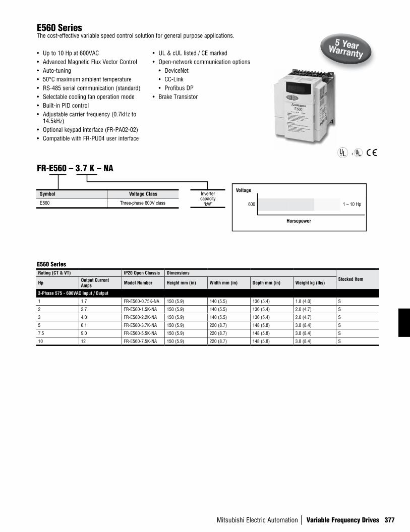
E560 SeriesThe cost-effective variable speed control solution for general purpose applications.
• Up to 10 Hp at 600VAC• Advanced Magnetic Flux Vector Control• Auto-tuning• 50°C maximum ambient temperature• RS-485 serial communication (standard)• Selectable cooling fan operation mode• Built-in PID control• Adjustable carrier frequency (0.7kHz to
14.5kHz)• Optional keypad interface (FR-PA02-02)• Compatible with FR-PU04 user interface
• UL & cUL listed / CE marked• Open-network communication options
• DeviceNet• CC-Link• Profibus DP
• Brake Transistor
Rating (CT & VT) IP20 Open Chassis DimensionsStocked Item
Hp Output Current Amps Model Number Height mm (in) Width mm (in) Depth mm (in) Weight kg (lbs)
3-Phase 575 - 600VAC Input / Output
1 1.7 FR-E560-0.75K-NA 150 (5.9) 140 (5.5) 136 (5.4) 1.8 (4.0) S
2 2.7 FR-E560-1.5K-NA 150 (5.9) 140 (5.5) 136 (5.4) 2.0 (4.7) S
3 4.0 FR-E560-2.2K-NA 150 (5.9) 140 (5.5) 136 (5.4) 2.0 (4.7) S
5 6.1 FR-E560-3.7K-NA 150 (5.9) 220 (8.7) 148 (5.8) 3.8 (8.4) S
7.5 9.0 FR-E560-5.5K-NA 150 (5.9) 220 (8.7) 148 (5.8) 3.8 (8.4) S
10 12 FR-E560-7.5K-NA 150 (5.9) 220 (8.7) 148 (5.8) 3.8 (8.4) S
E560 Series
Symbol Voltage Class
E560 Three-phase 600V class
FR-E560 – 3.7 K – NA
Invertercapacity
“kW”
Voltage
600 1 – 10 Hp
Horsepower
378
n V
ARIA
BLE
FREQ
UENC
Y DR
IVES
E560 General Specifications
Cont
rol S
peci
ficat
ions
Control Method Soft-PWM control / high carrier frequency PWM control can be selected. V / F control or general-purpose magnetic flux vector control can be selected.
Output Frequency Range 0.2 to 400Hz (starting frequency variable between 0 and 60Hz)
Frequency Control Analog Input Across terminals 2-5: 1/500 of maximum set frequency (5VDC input), 1/1000 (10VDC, 4-20mADC input). Digital Input 0.01Hz (less than 100Hz), 0.1Hz (100Hz or more) when digital setting is made using the control panel.
Frequency Precision Analog Input Within ±0.5% of maximum output frequency (25°C ±10°C) / 59°F to 95°F. Digital Input Within 0.01% of set output frequency when setting is made from control panel.
Voltage / Frequency Characteristics Base frequency set as required between 0 and 400Hz. Constant torque or variable torque pattern can be selected.
Starting Torque 150% or more (at 1Hz), 200% or more (at 3Hz) when general-purpose magnetic flux vector control or slip compensation is selected.
Torque Boost Manual torque boost, 0 to 30% may be set.
Acceleration / Deceleration Time Setting 0.01, 0.1 to 3600 sec. (accel. and decel. can be set individually), linear or S-pattern accel./decel. mode can be selected
Braking Torque Regenerative 0.1K, 0.2K...150% or more, 0.4K, 0.75K... 00% or more, 1.5K...50% or more, 2.2K, 3.7K, 5.5K, 7.5K ... 20% or
more (*1) DC Dynamic Brake Operation frequency (0 to 120Hz), operation time (0 to 10 s), operation voltage (0 to 30%) variable.
Stall Prevention Operation Level Operation current level can be set (0 to 200% variable), presence or absence can be selected. Voltage Stall Prevention Operation Level Operation level is fixed, presence or absence can be selected. Fast-Response Current Limit Level Operation level is fixed, presence or absence can be selected.
Inpu
t Sig
nals
Frequency Setting Signal
Analog Input 0 to 5VDC, 0 to 10VDC, 4 to 20mADC. Digital Input Entered from control panel (FR-PA02-02).
Starting Signal Forward and reverse rotation, start signal automatic self-holding input (3-wire input) can be selected. Alarm Reset Used to reset alarm output provided when protective function is activated.
Multi-Speed Selection Up to 15 speeds can be selected. (Each speed can be set between 0 and 400Hz, running speed can be changed during operation from the control panel.)
Second Function Selection Used to select second functions (accel. time, decel. time, torque boost, freq., electronic overcurrent protection).
Use Pr. 180 to Pr. 183 for selec-tion.
Output Stop Instantaneous shut-off of inverter output (frequency, voltage). Current Input Selection Used to select input of frequency setting signal 4 to 20mADC (terminal 4). Start Signal Automatic Self-Holding Selection Used to select start signal automatic self-holding input. (3-wire input) External Thermal Relay Input Thermal relay contact input for use when the inverter is stopped by the external thermal relay. PU Operation-External Operation Switching Used to switch between PU operation and external operation from outside the inverter. V/F-General-Purpose Magnetic Flux Switching Used to switch between V/F control and general-purpose magnetic flux vector from outside the inverter.
Operation Functions
Maximum/minimum frequency setting, frequency jump operation, external thermal relay input selec-tion, automatic restart operation after instantaneous power failure, forward/reverse rotation prevention, slip comp., operation mode selection, off-line auto tuning function, PID control, computer link opera-tion (RS-485).
Output SignalsOperation Status
2 open collector output signals can be selected from inverter running, up to frequency, frequency detection, over-load alarm, zero current detection, output current detection, PID upper limit, PID lower limit, PID forward/reverse rotation, operation ready, minor fault and alarm, and 1 contact output (230VAC 0.3A, 30VDC 0.3A) can be selected.
For Meter 1 signal can be selected from output frequency, motor current and output voltage. Pulse train output (1440 pulses/second/full scale).
Disp
lay
Control Panel Display Operating Status Output voltage, output current, set frequency, running. Alarm Definition Alarm definition is displayed when protective function is activated. 4 alarm definitions are stored.
LED Display Power application (POWER)
Protective And Warning Functions
Overcurrent shut-off (during acceleration, deceleration, constant speed), regenerative overvoltage shut-off, undervoltage (*2) , instantaneous power failure (*2), overload shut-off (electronic overcurrent protection), brake transistor alarm, output short circuit, stall prevention, brake resistor overheat protection, fan overheat, fan failure, parameter error, PU disconnection, ground fault protection.
Envi
ronm
ent
Ambient Temperature Constant torque: -10°C to +50°C (non-freezing) 14°F to 122°F Ambient Humidity 90%RH or less (non-condensing) Storage Temperature (*3 ) -20°C to +65°C / -4°F to 149°F Atmosphere Indoors, no corrosive and flammable gases, oil mist, dust and dirt.
Altitude Maximum 1000m (3300 ft.) above sea level for standard operation. After that derate by 3% for every extra 500m up to 2500m (91%).
Vibration 5.9 m/s2 (0.6G max.) based on JIS C 0911.
Notes:1. The braking torque indicated is a short-duration average torque (which varies with motor loss) when the motor alone is decelerated from 60Hz in the shortest time and is not a continuous regenerative torque.
When the motor is decelerated from the frequency higher than the base frequency, the average deceleration torque will reduce. Since the inverter does not contain a brake resistor, use the optional brake resistor when regenerative energy is large. (The optional brake resistor cannot be used with 0.1K and 0.2K.) A brake unit (BU) may also be used.
2. When undervoltage or instantaneous power failure has occurred, alarm display or alarm output is not provided but the inverter itself is protected. Overcurrent, regenerative overvoltage or other protection may be activated at power restoration according to the operating status (load size, etc.).
3. Temperature applicable for a short period in transit, etc.
Mitsubishi Electric Automation | Variable Frequency Drives 379
3-phase AC power supply
MCCB
STF
STR
RH
RM
RL
MRS
RES
Forward rotation start
Middle
High
Low
Output stop
Reset
Frequency setting signals (Analog)
10(+5V)
22
3
1
4 to 20mADC(+) 4(4 to 20mADC)
1/2W1kΩ
RUN
FU
SE
Running
Frequency detection
JumperRemove this jumper when using the optional power-factor improving DC reactor.
Brake resistor connection
Motor
IM
Alarmoutput
A
B
C
UVW
P1
PR
0 to 5VDC0 to 10VDC
Selected
Multi-speed selection
5
(Note 1)Frequencysettingpotentiometer
Current input(-)
Reverse rotation start
MC
Main circuit terminalControl circuit input terminalControl circuit output terminal
When using current input as the frequency setting signal, set "4" in any of Pr.180 to Pr.183 (input terminal function selection) and assign AU (current input selection) to any of terminal RH, RM, RL, or MRS, then turn the AU signal on.
(- )
AM
5
(+) Analog signal output(0 to 10VDC)
GroundPU connector(RS-485)
Contact input common
Control input signals (No voltage input allowed)
SDNote 3
SDNote 2
PC24VDC power output and
external transistor commonNote 4
R(L 1)S(L2)T(L 3 )
(+)P
(-)N
Note 3
Ground
Ground
Note 2
(Common)
Open collector output commonSink/source common
Opencollector outputs
Notes:1. If the potentiometer is to be operated often use a 2W1kΩ potentiometer. 2. Terminals SD and SE are electrically isolated.3. Terminals SD and 5 are common. Do not connect them to each other or to ground.4. To avoid damage to the VFD, do not allow a short circuit between terminals PC and SD. If they are shorted, the VFD will be damaged
E500 Series Terminal Connection Diagram Terminal Block Layout600V class
Model Number Description Notes Stocked Item
FR-PA02-02 Keypad for E500 VFD For mounting on E500 VFD S
FR-E5P Keypad Panel Mounting Adapter For use only on FR-PA02-02 and FR-CB20 S
FR-DU04 LED Parameter Unit Also used with A500(L). S
FR-PU04 LCD Parameter Unit Also used with A500(L). S
FR-E5ND E560 DeviceNet Interface Plug-in Option. Not for use with E520 or E510W. -
FR-E5NP E560 Profibus DP Interface Plug-in Option. Not for use with E520 or E510W. S
FR-E5NC E560 CC-Link Interface Plug-in Option. Not for use with E520 or E510W. -
FR-E5NL E560 LonWorks Interface Plug-in Option. Not for use with E520 or E510W. -
FR-CB201 Remote cable 1m cable S
FR-CB203 Remote Cable 3m cable S
FR-CB205 Remote Cable 5m cable S
SH(NA)3193 FR-A500 / E500 Technical Manual Only available for download. -
IB(NA)0600003 FR-E5NC, CC-Link Instruction Manual Only available for download. -
IB(NA)0600006 FR-E5ND, DeviceNet Instruction Manual Only available for download. -
IB(NA)0600007 FR-E5NP, Profibus Instruction Manual Only available for download. -
IB(NA)0600204 FR-E560 Instruction Manual Only available for download. -
SC-FRPC Serial Communication Cable S
E500 Series Options
RHRMRL
MRSRESSDAMPCSE
RUNFU
ABC10254
SDSTFSTRSD
380
n V
ARIA
BLE
FREQ
UENC
Y DR
IVES
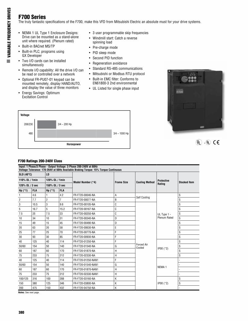
F700 SeriesThe truly fantastic specifications of the F700, make this VFD from Mitsubishi Electric an absolute must for your drive systems.
• NEMA 1 UL Type 1 Enclosure Designs: Drive can be mounted as a stand-alone unit where required. (Plenum rated)
• Built-in BACnet MS/TP• Built-in PLC; programs using
GX Developer• Two I/O cards can be installed
simultaneously• Remote I/O capability: All the drive I/O can
be read or controlled over a network• Optional FR-PU07-01 keypad can be
mounted remotely, display HAND/AUTO, and display the value of three monitors
• Energy Savings: Optimum Excitation Control
• 3 user programmable skip frequencies• Windmill start: Catch a reverse
spinning load• Pre-charge mode• PID sleep mode• Second PID function• Regeneration avoidance• Standard RS-485 communications• Mitsubishi or Modbus RTU protocol• Built-in EMC filter: Conforms to
EN61800-3 2nd environmental• UL Listed for single phase input
Notes: See next page.
Input: 1 Phase/3 Phase - Output Voltage: 3 Phase 200-240V at 60Hz Voltage Tolerance: 170-264V at 60Hz Available Braking Torque: 15% Torque Continuous
SLD (40°C) LD
Model Number (*4) Frame Size Cooling Method Protective Rating Stocked Item
110% OL / 1min 120% OL / 1min
120% OL / 3 sec 150% OL / 3 sec
Hp (*1) FLA Hp (*1) FLA
1 4.6 1 4.2 FR-F720-00046-NA ASelf Cooling
UL Type 1 - Plenum Rated
S
2 7.7 2 7 FR-F720-00077-NA B S
3 10.5 3 9.6 FR-F720-00105-NA C
Forced Air Cooled
S
5 16.7 5 15.2 FR-F720-00167-NA C S
7.5 25 7.5 23 FR-F720-00250-NA C S
10 34 10 31 FR-F720-00340-NA D S
15 49 15 45 FR-F720-00490-NA D S
20 63 20 58 FR-F720-00630-NA E S
25 77 25 70 FR-F720-00770-NA F S
30 93 30 85 FR-F720-00930-NA F S
40 125 40 114 FR-F720-01250-NA F
IP00 (*2)
S
50/60 154 50 140 FR-F720-01540-NA G S
60 187 60 170 FR-F720-01870-NA H S
75 233 75 212 FR-F720-02330-NA H S
40 125 40 114 FR-F720-01250-NAN1 F
NEMA 1
-
50/60 154 50 140 FR-F720-01540-NAN1 G -
60 187 60 170 FR-F720-01870-NAN1 H -
75 233 75 212 FR-F720-02330-NAN1 H -
100/125 316 100 288 FR-F720-03160-NA K
IP00 (*2)
S
150 380 125 346 FR-F720-03800-NA K S
200 475 150 432 FR-F720-04750-NA K -
F700 Ratings 200-240V Class
Voltage
208/230 3/4 – 200 Hp
480 3/4 – 1000 Hp
Horsepower
Mitsubishi Electric Automation | Variable Frequency Drives 381
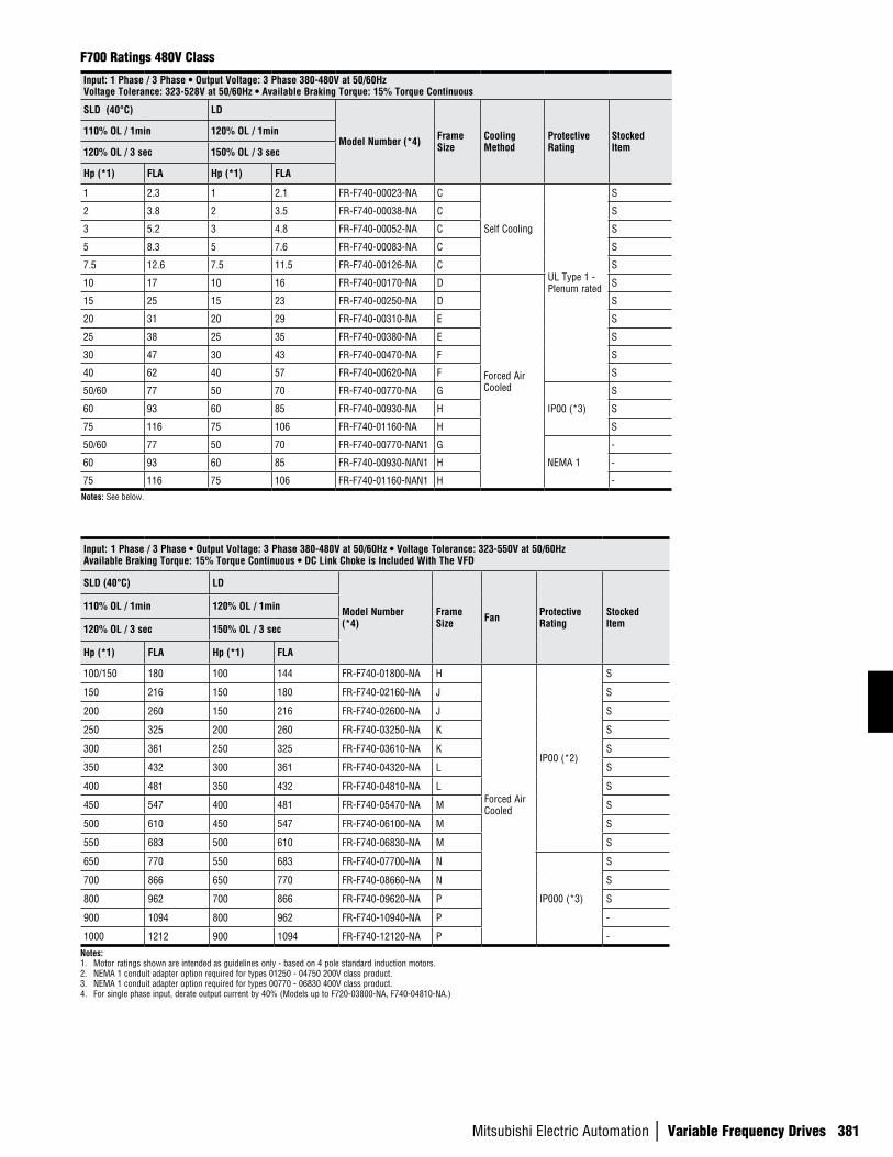
Notes:1. Motor ratings shown are intended as guidelines only - based on 4 pole standard induction motors.2. NEMA 1 conduit adapter option required for types 01250 - 04750 200V class product.3. NEMA 1 conduit adapter option required for types 00770 - 06830 400V class product.4. For single phase input, derate output current by 40% (Models up to F720-03800-NA, F740-04810-NA.)
Input: 1 Phase / 3 Phase • Output Voltage: 3 Phase 380-480V at 50/60Hz • Voltage Tolerance: 323-550V at 50/60HzAvailable Braking Torque: 15% Torque Continuous • DC Link Choke is Included With The VFD
SLD (40°C) LD
Model Number (*4)
Frame Size Fan Protective
RatingStocked Item
110% OL / 1min 120% OL / 1min
120% OL / 3 sec 150% OL / 3 sec
Hp (*1) FLA Hp (*1) FLA
100/150 180 100 144 FR-F740-01800-NA H
Forced Air Cooled
IP00 (*2)
S
150 216 150 180 FR-F740-02160-NA J S
200 260 150 216 FR-F740-02600-NA J S
250 325 200 260 FR-F740-03250-NA K S
300 361 250 325 FR-F740-03610-NA K S
350 432 300 361 FR-F740-04320-NA L S
400 481 350 432 FR-F740-04810-NA L S
450 547 400 481 FR-F740-05470-NA M S
500 610 450 547 FR-F740-06100-NA M S
550 683 500 610 FR-F740-06830-NA M S
650 770 550 683 FR-F740-07700-NA N
IP000 (*3)
S
700 866 650 770 FR-F740-08660-NA N S
800 962 700 866 FR-F740-09620-NA P S
900 1094 800 962 FR-F740-10940-NA P -
1000 1212 900 1094 FR-F740-12120-NA P -
F700 Ratings 480V Class
Input: 1 Phase / 3 Phase • Output Voltage: 3 Phase 380-480V at 50/60Hz Voltage Tolerance: 323-528V at 50/60Hz • Available Braking Torque: 15% Torque Continuous
SLD (40°C) LD
Model Number (*4) Frame Size
Cooling Method
Protective Rating
Stocked Item
110% OL / 1min 120% OL / 1min
120% OL / 3 sec 150% OL / 3 sec
Hp (*1) FLA Hp (*1) FLA
1 2.3 1 2.1 FR-F740-00023-NA C
Self Cooling
UL Type 1 - Plenum rated
S
2 3.8 2 3.5 FR-F740-00038-NA C S
3 5.2 3 4.8 FR-F740-00052-NA C S
5 8.3 5 7.6 FR-F740-00083-NA C S
7.5 12.6 7.5 11.5 FR-F740-00126-NA C S
10 17 10 16 FR-F740-00170-NA D
Forced Air Cooled
S
15 25 15 23 FR-F740-00250-NA D S
20 31 20 29 FR-F740-00310-NA E S
25 38 25 35 FR-F740-00380-NA E S
30 47 30 43 FR-F740-00470-NA F S
40 62 40 57 FR-F740-00620-NA F S
50/60 77 50 70 FR-F740-00770-NA G
IP00 (*3)
S
60 93 60 85 FR-F740-00930-NA H S
75 116 75 106 FR-F740-01160-NA H S
50/60 77 50 70 FR-F740-00770-NAN1 G
NEMA 1
-
60 93 60 85 FR-F740-00930-NAN1 H -
75 116 75 106 FR-F740-01160-NAN1 H -Notes: See below.
382
n V
ARIA
BLE
FREQ
UENC
Y DR
IVES
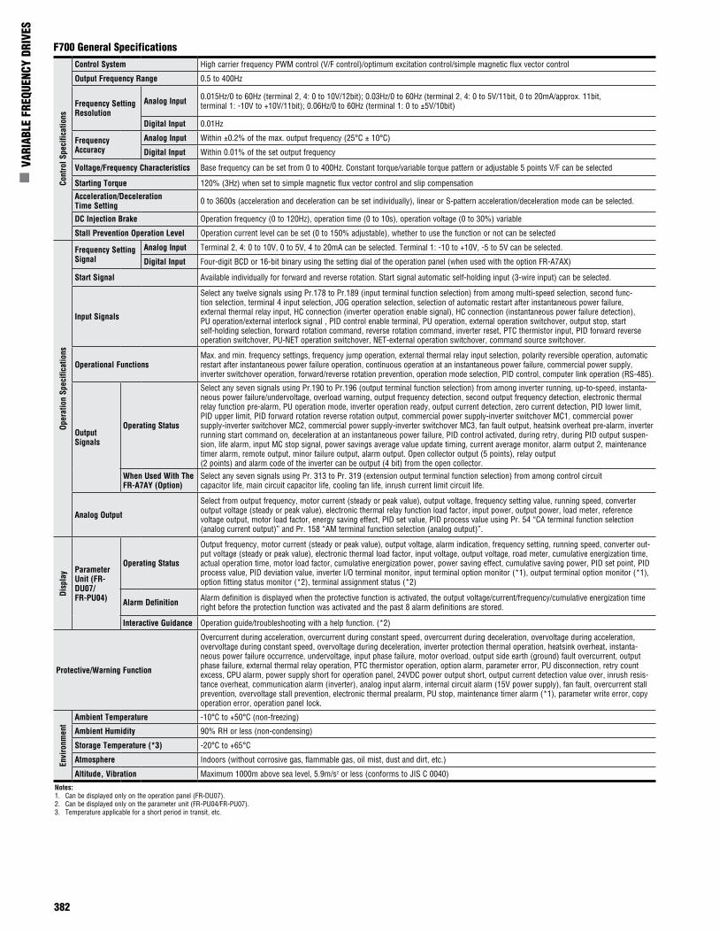
Cont
rol S
peci
ficat
ions
Control System High carrier frequency PWM control (V/F control)/optimum excitation control/simple magnetic flux vector control
Output Frequency Range 0.5 to 400Hz
Frequency Setting Resolution
Analog Input 0.015Hz/0 to 60Hz (terminal 2, 4: 0 to 10V/12bit); 0.03Hz/0 to 60Hz (terminal 2, 4: 0 to 5V/11bit, 0 to 20mA/approx. 11bit, terminal 1: -10V to +10V/11bit); 0.06Hz/0 to 60Hz (terminal 1: 0 to ±5V/10bit)
Digital Input 0.01Hz
Frequency Accuracy
Analog Input Within ±0.2% of the max. output frequency (25°C ± 10°C)
Digital Input Within 0.01% of the set output frequency
Voltage/Frequency Characteristics Base frequency can be set from 0 to 400Hz. Constant torque/variable torque pattern or adjustable 5 points V/F can be selected
Starting Torque 120% (3Hz) when set to simple magnetic flux vector control and slip compensation
Acceleration/Deceleration Time Setting 0 to 3600s (acceleration and deceleration can be set individually), linear or S-pattern acceleration/deceleration mode can be selected.
DC Injection Brake Operation frequency (0 to 120Hz), operation time (0 to 10s), operation voltage (0 to 30%) variable
Stall Prevention Operation Level Operation current level can be set (0 to 150% adjustable), whether to use the function or not can be selected
Oper
atio
n Sp
ecifi
catio
ns
Frequency Setting Signal
Analog Input Terminal 2, 4: 0 to 10V, 0 to 5V, 4 to 20mA can be selected. Terminal 1: -10 to +10V, -5 to 5V can be selected.
Digital Input Four-digit BCD or 16-bit binary using the setting dial of the operation panel (when used with the option FR-A7AX)
Start Signal Available individually for forward and reverse rotation. Start signal automatic self-holding input (3-wire input) can be selected.
Input Signals
Select any twelve signals using Pr.178 to Pr.189 (input terminal function selection) from among multi-speed selection, second func-tion selection, terminal 4 input selection, JOG operation selection, selection of automatic restart after instantaneous power failure, external thermal relay input, HC connection (inverter operation enable signal), HC connection (instantaneous power failure detection), PU operation/external interlock signal , PID control enable terminal, PU operation, external operation switchover, output stop, start self-holding selection, forward rotation command, reverse rotation command, inverter reset, PTC thermistor input, PID forward reverse operation switchover, PU-NET operation switchover, NET-external operation switchover, command source switchover.
Operational FunctionsMax. and min. frequency settings, frequency jump operation, external thermal relay input selection, polarity reversible operation, automatic restart after instantaneous power failure operation, continuous operation at an instantaneous power failure, commercial power supply, inverter switchover operation, forward/reverse rotation prevention, operation mode selection, PID control, computer link operation (RS-485).
Output Signals
Operating Status
Select any seven signals using Pr.190 to Pr.196 (output terminal function selection) from among inverter running, up-to-speed, instanta-neous power failure/undervoltage, overload warning, output frequency detection, second output frequency detection, electronic thermal relay function pre-alarm, PU operation mode, inverter operation ready, output current detection, zero current detection, PID lower limit, PID upper limit, PID forward rotation reverse rotation output, commercial power supply-inverter switchover MC1, commercial power supply-inverter switchover MC2, commercial power supply-inverter switchover MC3, fan fault output, heatsink overheat pre-alarm, inverter running start command on, deceleration at an instantaneous power failure, PID control activated, during retry, during PID output suspen-sion, life alarm, input MC stop signal, power savings average value update timing, current average monitor, alarm output 2, maintenance timer alarm, remote output, minor failure output, alarm output. Open collector output (5 points), relay output (2 points) and alarm code of the inverter can be output (4 bit) from the open collector.
When Used With The FR-A7AY (Option)
Select any seven signals using Pr. 313 to Pr. 319 (extension output terminal function selection) from among control circuit capacitor life, main circuit capacitor life, cooling fan life, inrush current limit circuit life.
Analog Output
Select from output frequency, motor current (steady or peak value), output voltage, frequency setting value, running speed, converter output voltage (steady or peak value), electronic thermal relay function load factor, input power, output power, load meter, reference voltage output, motor load factor, energy saving effect, PID set value, PID process value using Pr. 54 “CA terminal function selection (analog current output)” and Pr. 158 “AM terminal function selection (analog output)”.
Disp
lay Parameter
Unit (FR-DU07/FR-PU04)
Operating Status
Output frequency, motor current (steady or peak value), output voltage, alarm indication, frequency setting, running speed, converter out-put voltage (steady or peak value), electronic thermal load factor, input voltage, output voltage, road meter, cumulative energization time, actual operation time, motor load factor, cumulative energization power, power saving effect, cumulative saving power, PID set point, PID process value, PID deviation value, inverter I/O terminal monitor, input terminal option monitor (*1), output terminal option monitor (*1), option fitting status monitor (*2), terminal assignment status (*2)
Alarm Definition Alarm definition is displayed when the protective function is activated, the output voltage/current/frequency/cumulative energization time right before the protection function was activated and the past 8 alarm definitions are stored.
Interactive Guidance Operation guide/troubleshooting with a help function. (*2)
Protective/Warning Function
Overcurrent during acceleration, overcurrent during constant speed, overcurrent during deceleration, overvoltage during acceleration, overvoltage during constant speed, overvoltage during deceleration, inverter protection thermal operation, heatsink overheat, instanta-neous power failure occurrence, undervoltage, input phase failure, motor overload, output side earth (ground) fault overcurrent, output phase failure, external thermal relay operation, PTC thermistor operation, option alarm, parameter error, PU disconnection, retry count excess, CPU alarm, power supply short for operation panel, 24VDC power output short, output current detection value over, inrush resis-tance overheat, communication alarm (inverter), analog input alarm, internal circuit alarm (15V power supply), fan fault, overcurrent stall prevention, overvoltage stall prevention, electronic thermal prealarm, PU stop, maintenance timer alarm (*1), parameter write error, copy operation error, operation panel lock.
Envi
ronm
ent
Ambient Temperature -10°C to +50°C (non-freezing)
Ambient Humidity 90% RH or less (non-condensing)
Storage Temperature (*3) -20°C to +65°C
Atmosphere Indoors (without corrosive gas, flammable gas, oil mist, dust and dirt, etc.)
Altitude, Vibration Maximum 1000m above sea level, 5.9m/s2 or less (conforms to JIS C 0040)
Notes:1. Can be displayed only on the operation panel (FR-DU07). 2. Can be displayed only on the parameter unit (FR-PU04/FR-PU07). 3. Temperature applicable for a short period in transit, etc.
F700 General Specifications
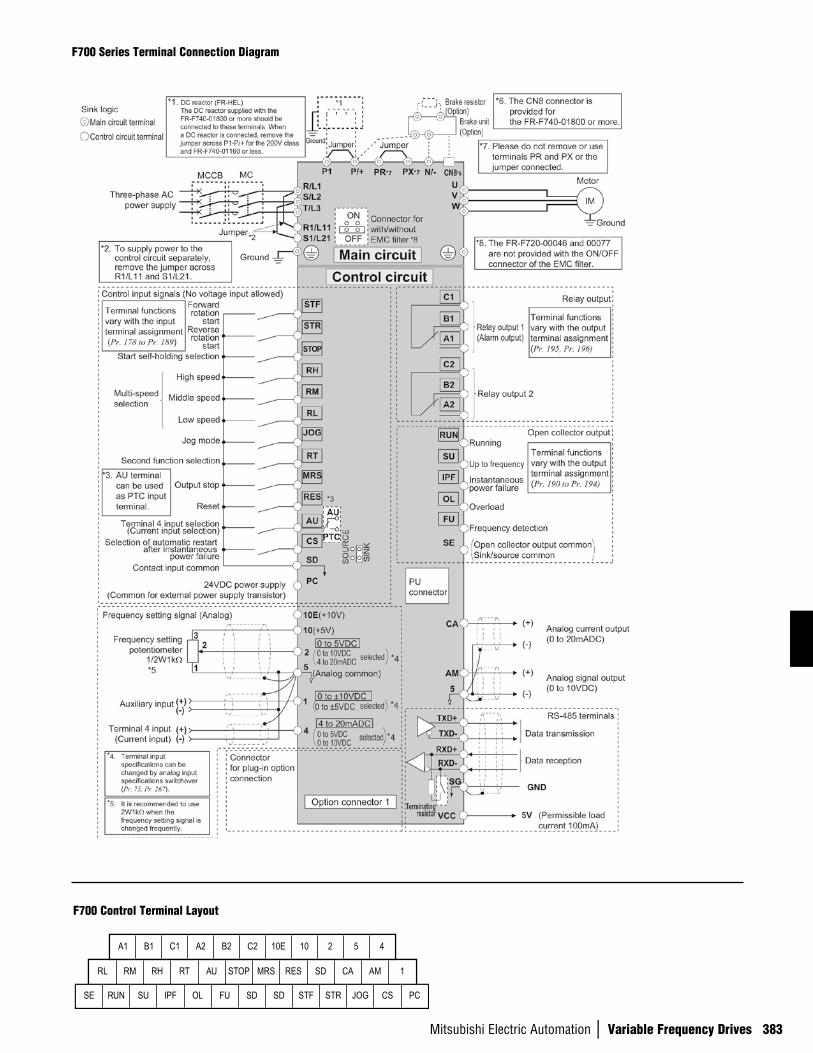
Mitsubishi Electric Automation | Variable Frequency Drives 383
F700 Series Terminal Connection Diagram
F700 Control Terminal Layout
A1 B1 C1 A2 B2 C2 10E 10 2 5 4
RL RM RH RT AU STOP MRS RES SD CA AM 1
SE RUN SU IPF OL FU SD SD STF STR JOG CS PC
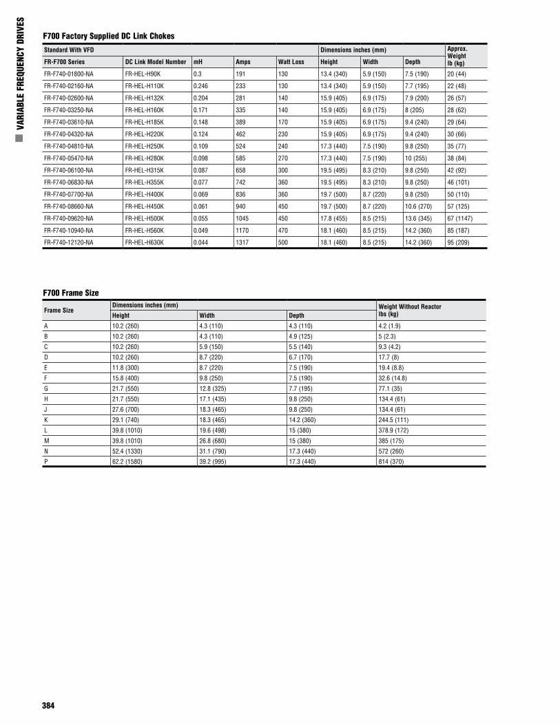
384
n V
ARIA
BLE
FREQ
UENC
Y DR
IVES
F700 Factory Supplied DC Link Chokes
F700 Frame Size
Standard With VFD Dimensions inches (mm) Approx. Weightlb (kg)FR-F700 Series DC Link Model Number mH Amps Watt Loss Height Width Depth
FR-F740-01800-NA FR-HEL-H90K 0.3 191 130 13.4 (340) 5.9 (150) 7.5 (190) 20 (44)
FR-F740-02160-NA FR-HEL-H110K 0.246 233 130 13.4 (340) 5.9 (150) 7.7 (195) 22 (48)
FR-F740-02600-NA FR-HEL-H132K 0.204 281 140 15.9 (405) 6.9 (175) 7.9 (200) 26 (57)
FR-F740-03250-NA FR-HEL-H160K 0.171 335 140 15.9 (405) 6.9 (175) 8 (205) 28 (62)
FR-F740-03610-NA FR-HEL-H185K 0.148 389 170 15.9 (405) 6.9 (175) 9.4 (240) 29 (64)
FR-F740-04320-NA FR-HEL-H220K 0.124 462 230 15.9 (405) 6.9 (175) 9.4 (240) 30 (66)
FR-F740-04810-NA FR-HEL-H250K 0.109 524 240 17.3 (440) 7.5 (190) 9.8 (250) 35 (77)
FR-F740-05470-NA FR-HEL-H280K 0.098 585 270 17.3 (440) 7.5 (190) 10 (255) 38 (84)
FR-F740-06100-NA FR-HEL-H315K 0.087 658 300 19.5 (495) 8.3 (210) 9.8 (250) 42 (92)
FR-F740-06830-NA FR-HEL-H355K 0.077 742 360 19.5 (495) 8.3 (210) 9.8 (250) 46 (101)
FR-F740-07700-NA FR-HEL-H400K 0.069 836 360 19.7 (500) 8.7 (220) 9.8 (250) 50 (110)
FR-F740-08660-NA FR-HEL-H450K 0.061 940 450 19.7 (500) 8.7 (220) 10.6 (270) 57 (125)
FR-F740-09620-NA FR-HEL-H500K 0.055 1045 450 17.8 (455) 8.5 (215) 13.6 (345) 67 (1147)
FR-F740-10940-NA FR-HEL-H560K 0.049 1170 470 18.1 (460) 8.5 (215) 14.2 (360) 85 (187)
FR-F740-12120-NA FR-HEL-H630K 0.044 1317 500 18.1 (460) 8.5 (215) 14.2 (360) 95 (209)
Frame SizeDimensions inches (mm) Weight Without Reactor
lbs (kg)Height Width Depth
A 10.2 (260) 4.3 (110) 4.3 (110) 4.2 (1.9)
B 10.2 (260) 4.3 (110) 4.9 (125) 5 (2.3)
C 10.2 (260) 5.9 (150) 5.5 (140) 9.3 (4.2)
D 10.2 (260) 8.7 (220) 6.7 (170) 17.7 (8)
E 11.8 (300) 8.7 (220) 7.5 (190) 19.4 (8.8)
F 15.8 (400) 9.8 (250) 7.5 (190) 32.6 (14.8)
G 21.7 (550) 12.8 (325) 7.7 (195) 77.1 (35)
H 21.7 (550) 17.1 (435) 9.8 (250) 134.4 (61)
J 27.6 (700) 18.3 (465) 9.8 (250) 134.4 (61)
K 29.1 (740) 18.3 (465) 14.2 (360) 244.5 (111)
L 39.8 (1010) 19.6 (498) 15 (380) 378.9 (172)
M 39.8 (1010) 26.8 (680) 15 (380) 385 (175)
N 52.4 (1330) 31.1 (790) 17.3 (440) 572 (260)
P 62.2 (1580) 39.2 (995) 17.3 (440) 814 (370)
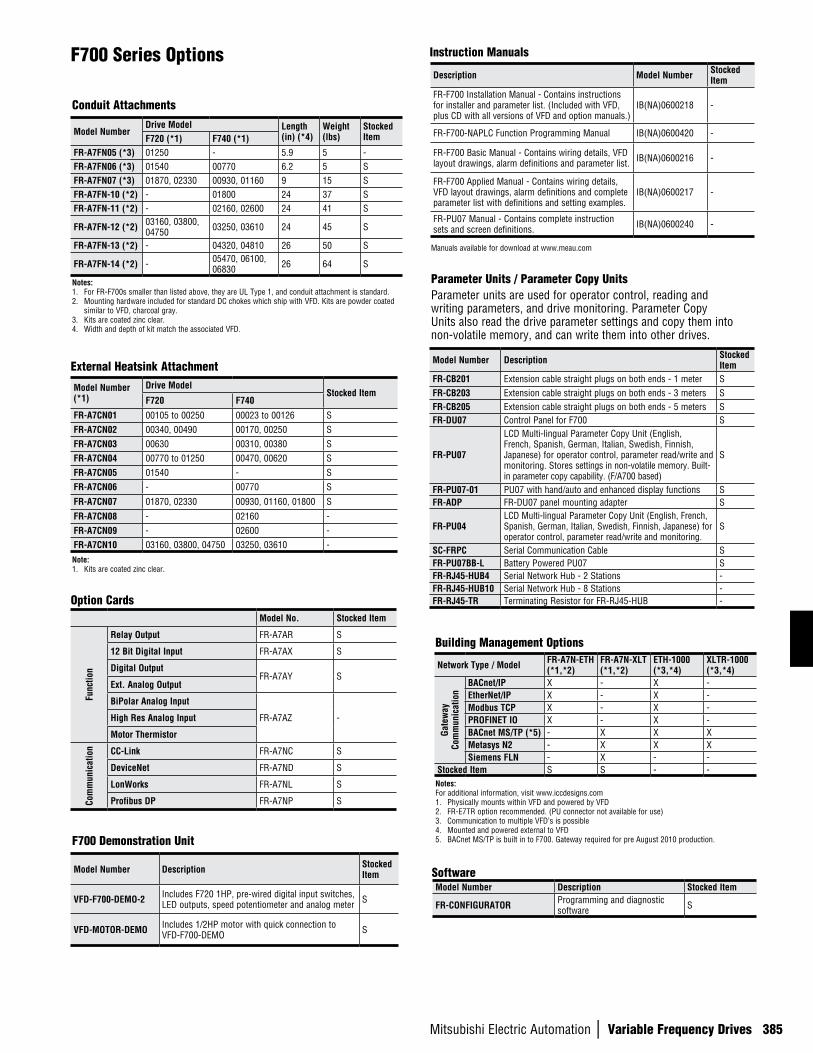
Mitsubishi Electric Automation | Variable Frequency Drives 385
F700 Series Options
Conduit Attachments
Instruction Manuals
Option Cards
External Heatsink Attachment Model Number Description Stocked Item
FR-CB201 Extension cable straight plugs on both ends - 1 meter SFR-CB203 Extension cable straight plugs on both ends - 3 meters SFR-CB205 Extension cable straight plugs on both ends - 5 meters SFR-DU07 Control Panel for F700 S
FR-PU07
LCD Multi-lingual Parameter Copy Unit (English, French, Spanish, German, Italian, Swedish, Finnish, Japanese) for operator control, parameter read/write and monitoring. Stores settings in non-volatile memory. Built-in parameter copy capability. (F/A700 based)
S
FR-PU07-01 PU07 with hand/auto and enhanced display functions SFR-ADP FR-DU07 panel mounting adapter S
FR-PU04LCD Multi-lingual Parameter Copy Unit (English, French, Spanish, German, Italian, Swedish, Finnish, Japanese) for operator control, parameter read/write and monitoring.
S
SC-FRPC Serial Communication Cable SFR-PU07BB-L Battery Powered PU07 SFR-RJ45-HUB4 Serial Network Hub - 2 Stations -FR-RJ45-HUB10 Serial Network Hub - 8 Stations -FR-RJ45-TR Terminating Resistor for FR-RJ45-HUB -
Notes:1. For FR-F700s smaller than listed above, they are UL Type 1, and conduit attachment is standard.2. Mounting hardware included for standard DC chokes which ship with VFD. Kits are powder coated
similar to VFD, charcoal gray.3. Kits are coated zinc clear.4. Width and depth of kit match the associated VFD.
Note:1. Kits are coated zinc clear.
Model Number (*1)
Drive ModelStocked Item
F720 F740
FR-A7CN01 00105 to 00250 00023 to 00126 SFR-A7CN02 00340, 00490 00170, 00250 SFR-A7CN03 00630 00310, 00380 SFR-A7CN04 00770 to 01250 00470, 00620 SFR-A7CN05 01540 - SFR-A7CN06 - 00770 S
FR-A7CN07 01870, 02330 00930, 01160, 01800 S
FR-A7CN08 - 02160 -FR-A7CN09 - 02600 -FR-A7CN10 03160, 03800, 04750 03250, 03610 -
Manuals available for download at www.meau.com
Description Model Number Stocked Item
FR-F700 Installation Manual - Contains instructions for installer and parameter list. (Included with VFD, plus CD with all versions of VFD and option manuals.)
IB(NA)0600218 -
FR-F700-NAPLC Function Programming Manual IB(NA)0600420 -
FR-F700 Basic Manual - Contains wiring details, VFD layout drawings, alarm definitions and parameter list. IB(NA)0600216 -
FR-F700 Applied Manual - Contains wiring details, VFD layout drawings, alarm definitions and complete parameter list with definitions and setting examples.
IB(NA)0600217 -
FR-PU07 Manual - Contains complete instruction sets and screen definitions. IB(NA)0600240 -
SoftwareModel Number Description Stocked Item
FR-CONFIGURATOR Programming and diagnostic software S
Model NumberDrive Model Length
(in) (*4)Weight (lbs)
Stocked ItemF720 (*1) F740 (*1)
FR-A7FN05 (*3) 01250 - 5.9 5 -FR-A7FN06 (*3) 01540 00770 6.2 5 SFR-A7FN07 (*3) 01870, 02330 00930, 01160 9 15 SFR-A7FN-10 (*2) - 01800 24 37 SFR-A7FN-11 (*2) - 02160, 02600 24 41 S
FR-A7FN-12 (*2) 03160, 03800, 04750 03250, 03610 24 45 S
FR-A7FN-13 (*2) - 04320, 04810 26 50 S
FR-A7FN-14 (*2) - 05470, 06100, 06830 26 64 S
Model No. Stocked Item
Func
tion
Relay Output FR-A7AR S
12 Bit Digital Input FR-A7AX S
Digital Output FR-A7AY S
Ext. Analog Output
BiPolar Analog Input
FR-A7AZ -High Res Analog Input
Motor Thermistor
Com
mun
icat
ion CC-Link FR-A7NC S
DeviceNet FR-A7ND S
LonWorks FR-A7NL S
Profibus DP FR-A7NP S
Model Number Description Stocked Item
VFD-F700-DEMO-2 Includes F720 1HP, pre-wired digital input switches, LED outputs, speed potentiometer and analog meter S
VFD-MOTOR-DEMO Includes 1/2HP motor with quick connection to VFD-F700-DEMO S
F700 Demonstration Unit
Parameter Units / Parameter Copy UnitsParameter units are used for operator control, reading and writing parameters, and drive monitoring. Parameter Copy Units also read the drive parameter settings and copy them into non-volatile memory, and can write them into other drives.
Building Management Options
Notes:For additional information, visit www.iccdesigns.com1. Physically mounts within VFD and powered by VFD2. FR-E7TR option recommended. (PU connector not available for use)3. Communication to multiple VFD’s is possible4. Mounted and powered external to VFD5. BACnet MS/TP is built in to F700. Gateway required for pre August 2010 production.
Network Type / Model FR-A7N-ETH (*1,*2)
FR-A7N-XLT (*1,*2)
ETH-1000(*3,*4)
XLTR-1000(*3,*4)
Gate
way
Co
mm
unic
atio
n
BACnet/IP X - X -EtherNet/IP X - X -Modbus TCP X - X -PROFINET IO X - X -BACnet MS/TP (*5) - X X XMetasys N2 - X X XSiemens FLN - X - -
Stocked Item S S - -
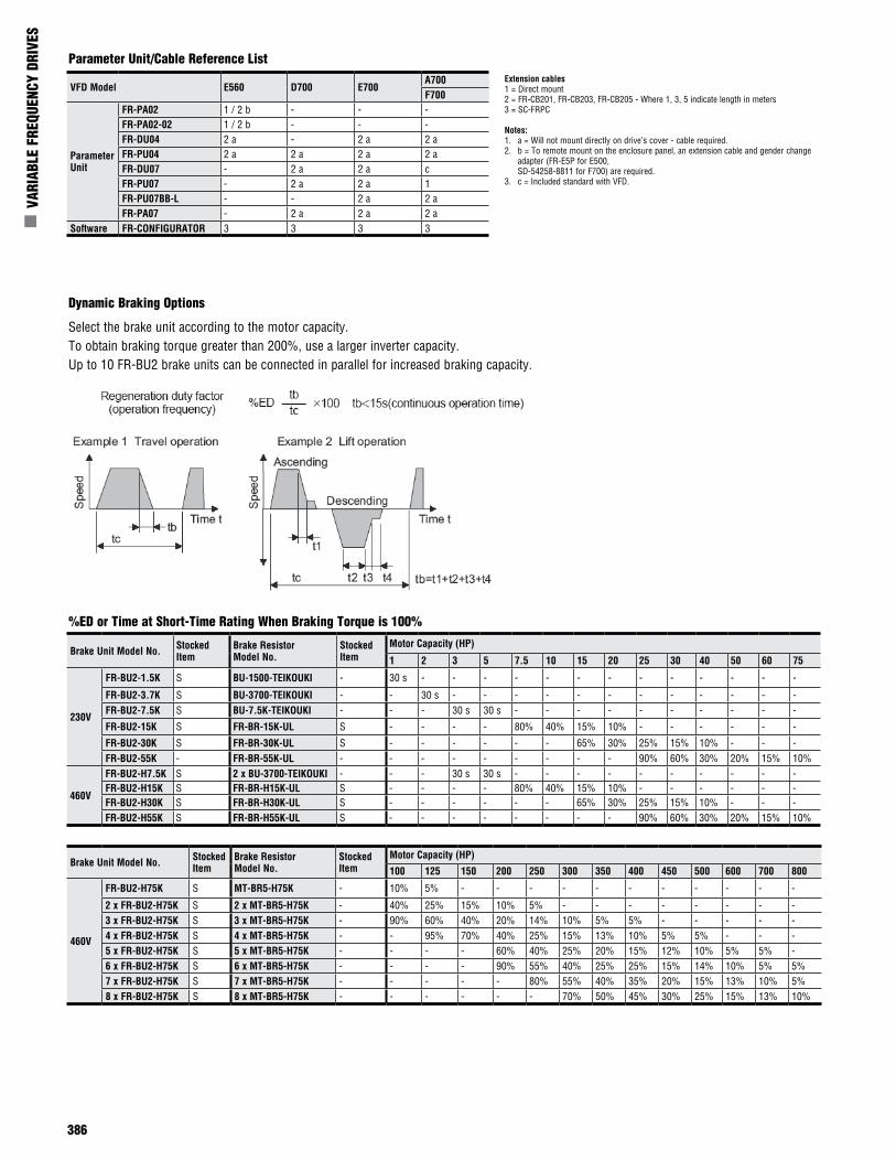
386
n V
ARIA
BLE
FREQ
UENC
Y DR
IVES
VFD Model E560 D700 E700A700F700
Parameter Unit
FR-PA02 1 / 2 b - - -FR-PA02-02 1 / 2 b - - -FR-DU04 2 a - 2 a 2 aFR-PU04 2 a 2 a 2 a 2 aFR-DU07 - 2 a 2 a cFR-PU07 - 2 a 2 a 1FR-PU07BB-L - - 2 a 2 aFR-PA07 - 2 a 2 a 2 a
Software FR-CONFIGURATOR 3 3 3 3
Extension cables1 = Direct mount2 = FR-CB201, FR-CB203, FR-CB205 - Where 1, 3, 5 indicate length in meters3 = SC-FRPC
Notes:1. a = Will not mount directly on drive’s cover - cable required.2. b = To remote mount on the enclosure panel, an extension cable and gender change
adapter (FR-E5P for E500, SD-54258-8811 for F700) are required.
3. c = Included standard with VFD.
Parameter Unit/Cable Reference List
Dynamic Braking Options
%ED or Time at Short-Time Rating When Braking Torque is 100%
Select the brake unit according to the motor capacity.To obtain braking torque greater than 200%, use a larger inverter capacity.Up to 10 FR-BU2 brake units can be connected in parallel for increased braking capacity.
Brake Unit Model No. Stocked Item
Brake Resistor Model No.
Stocked Item
Motor Capacity (HP)
1 2 3 5 7.5 10 15 20 25 30 40 50 60 75
230V
FR-BU2-1.5K S BU-1500-TEIKOUKI - 30 s - - - - - - - - - - - - -
FR-BU2-3.7K S BU-3700-TEIKOUKI - - 30 s - - - - - - - - - - - -FR-BU2-7.5K S BU-7.5K-TEIKOUKI - - - 30 s 30 s - - - - - - - - - -
FR-BU2-15K S FR-BR-15K-UL S - - - - 80% 40% 15% 10% - - - - - -
FR-BU2-30K S FR-BR-30K-UL S - - - - - - 65% 30% 25% 15% 10% - - -FR-BU2-55K - FR-BR-55K-UL - - - - - - - - - 90% 60% 30% 20% 15% 10%
460V
FR-BU2-H7.5K S 2 x BU-3700-TEIKOUKI - - - 30 s 30 s - - - - - - - - - -FR-BU2-H15K S FR-BR-H15K-UL S - - - - 80% 40% 15% 10% - - - - - -FR-BU2-H30K S FR-BR-H30K-UL S - - - - - - 65% 30% 25% 15% 10% - - -FR-BU2-H55K S FR-BR-H55K-UL S - - - - - - - - 90% 60% 30% 20% 15% 10%
Brake Unit Model No. Stocked Item
Brake Resistor Model No.
Stocked Item
Motor Capacity (HP)
100 125 150 200 250 300 350 400 450 500 600 700 800
460V
FR-BU2-H75K S MT-BR5-H75K - 10% 5% - - - - - - - - - - -
2 x FR-BU2-H75K S 2 x MT-BR5-H75K - 40% 25% 15% 10% 5% - - - - - - - -3 x FR-BU2-H75K S 3 x MT-BR5-H75K - 90% 60% 40% 20% 14% 10% 5% 5% - - - - -4 x FR-BU2-H75K S 4 x MT-BR5-H75K - - 95% 70% 40% 25% 15% 13% 10% 5% 5% - - -5 x FR-BU2-H75K S 5 x MT-BR5-H75K - - - - 60% 40% 25% 20% 15% 12% 10% 5% 5% -6 x FR-BU2-H75K S 6 x MT-BR5-H75K - - - - 90% 55% 40% 25% 25% 15% 14% 10% 5% 5%7 x FR-BU2-H75K S 7 x MT-BR5-H75K - - - - - 80% 55% 40% 35% 20% 15% 13% 10% 5%8 x FR-BU2-H75K S 8 x MT-BR5-H75K - - - - - - 70% 50% 45% 30% 25% 15% 13% 10%
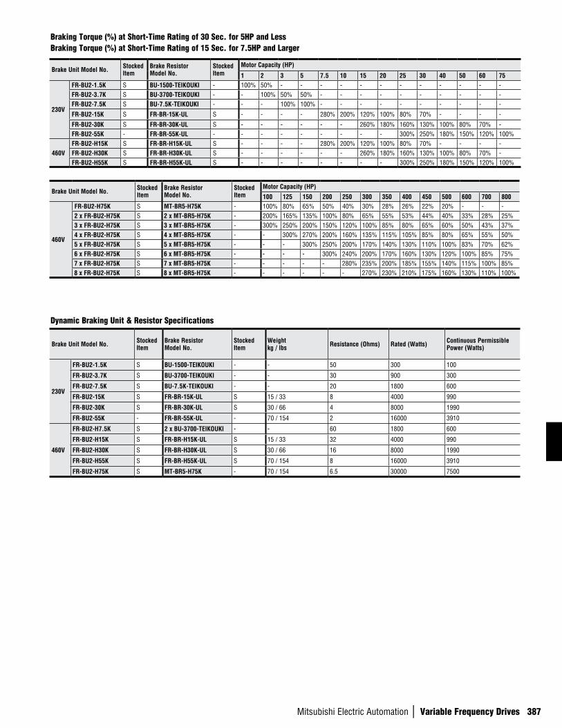
Mitsubishi Electric Automation | Variable Frequency Drives 387
Braking Torque (%) at Short-Time Rating of 30 Sec. for 5HP and LessBraking Torque (%) at Short-Time Rating of 15 Sec. for 7.5HP and Larger
Dynamic Braking Unit & Resistor Specifications
Brake Unit Model No. Stocked Item
Brake Resistor Model No.
Stocked Item
Motor Capacity (HP)
1 2 3 5 7.5 10 15 20 25 30 40 50 60 75
230V
FR-BU2-1.5K S BU-1500-TEIKOUKI - 100% 50% - - - - - - - - - - - -FR-BU2-3.7K S BU-3700-TEIKOUKI - - 100% 50% 50% - - - - - - - - - -FR-BU2-7.5K S BU-7.5K-TEIKOUKI - - - 100% 100% - - - - - - - - - -
FR-BU2-15K S FR-BR-15K-UL S - - - - 280% 200% 120% 100% 80% 70% - - - -
FR-BU2-30K S FR-BR-30K-UL S - - - - - - 260% 180% 160% 130% 100% 80% 70% -FR-BU2-55K - FR-BR-55K-UL - - - - - - - - - 300% 250% 180% 150% 120% 100%
460VFR-BU2-H15K S FR-BR-H15K-UL S - - - - 280% 200% 120% 100% 80% 70% - - - -FR-BU2-H30K S FR-BR-H30K-UL S - - - - - - 260% 180% 160% 130% 100% 80% 70% -FR-BU2-H55K S FR-BR-H55K-UL S - - - - - - - - 300% 250% 180% 150% 120% 100%
Brake Unit Model No. Stocked Item
Brake Resistor Model No.
Stocked Item
Motor Capacity (HP)
100 125 150 200 250 300 350 400 450 500 600 700 800
460V
FR-BU2-H75K S MT-BR5-H75K - 100% 80% 65% 50% 40% 30% 28% 26% 22% 20% - - -2 x FR-BU2-H75K S 2 x MT-BR5-H75K - 200% 165% 135% 100% 80% 65% 55% 53% 44% 40% 33% 28% 25%3 x FR-BU2-H75K S 3 x MT-BR5-H75K - 300% 250% 200% 150% 120% 100% 85% 80% 65% 60% 50% 43% 37%4 x FR-BU2-H75K S 4 x MT-BR5-H75K - - 300% 270% 200% 160% 135% 115% 105% 85% 80% 65% 55% 50%5 x FR-BU2-H75K S 5 x MT-BR5-H75K - - - 300% 250% 200% 170% 140% 130% 110% 100% 83% 70% 62%6 x FR-BU2-H75K S 6 x MT-BR5-H75K - - - - 300% 240% 200% 170% 160% 130% 120% 100% 85% 75%7 x FR-BU2-H75K S 7 x MT-BR5-H75K - - - - - 280% 235% 200% 185% 155% 140% 115% 100% 85%8 x FR-BU2-H75K S 8 x MT-BR5-H75K - - - - - - 270% 230% 210% 175% 160% 130% 110% 100%
Brake Unit Model No. Stocked Item
Brake Resistor Model No.
Stocked Item
Weight kg / lbs Resistance (Ohms) Rated (Watts) Continuous Permissible
Power (Watts)
230V
FR-BU2-1.5K S BU-1500-TEIKOUKI - - 50 300 100
FR-BU2-3.7K S BU-3700-TEIKOUKI - - 30 900 300
FR-BU2-7.5K S BU-7.5K-TEIKOUKI - - 20 1800 600
FR-BU2-15K S FR-BR-15K-UL S 15 / 33 8 4000 990
FR-BU2-30K S FR-BR-30K-UL S 30 / 66 4 8000 1990
FR-BU2-55K - FR-BR-55K-UL - 70 / 154 2 16000 3910
460V
FR-BU2-H7.5K S 2 x BU-3700-TEIKOUKI - - 60 1800 600
FR-BU2-H15K S FR-BR-H15K-UL S 15 / 33 32 4000 990
FR-BU2-H30K S FR-BR-H30K-UL S 30 / 66 16 8000 1990
FR-BU2-H55K S FR-BR-H55K-UL S 70 / 154 8 16000 3910
FR-BU2-H75K S MT-BR5-H75K - 70 / 154 6.5 30000 7500
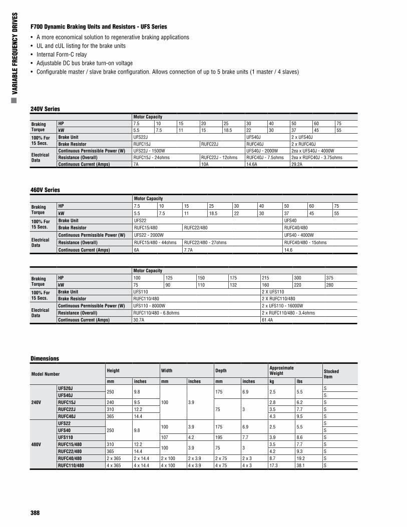
388
n V
ARIA
BLE
FREQ
UENC
Y DR
IVES
F700 Dynamic Braking Units and Resistors - UFS Series
• A more economical solution to regenerative braking applications• UL and cUL listing for the brake units• Internal Form-C relay• Adjustable DC bus brake turn-on voltage• Configurable master / slave brake configuration. Allows connection of up to 5 brake units (1 master / 4 slaves)
460V Series
Dimensions
Motor Capacity
Braking Torque
HP 7.5 10 15 20 25 30 40 50 60 75kW 5.5 7.5 11 15 18.5 22 30 37 45 55
100% For 15 Secs.
Brake Unit UFS22J UFS40J 2 x UFS40JBrake Resistor RUFC15J RUFC22J RUFC40J 2 x RUFC40J
Electrical Data
Continuous Permissible Power (W) UFS22J - 1500W UFS40J - 2000W 2ea x UFS40J - 4000WResistance (Overall) RUFC15J - 24ohms RUFC22J - 12ohms RUFC40J - 7.5ohms 2ea x RUFC40J - 3.75ohmsContinuous Current (Amps) 7A 10A 14.6A 29.2A
Motor Capacity
Braking Torque
HP 7.5 10 15 25 30 40 50 60 75
kW 5.5 7.5 11 18.5 22 30 37 45 55
100% For 15 Secs.
Brake Unit UFS22 UFS40Brake Resistor RUFC15/480 RUFC22/480 RUFC40/480
Electrical Data
Continuous Permissible Power (W) UFS22 - 2000W UFS40 - 4000W
Resistance (Overall) RUFC15/480 - 44ohms RUFC22/480 - 27ohms RUFC40/480 - 15ohms
Continuous Current (Amps) 6A 7.7A 14.6
Motor Capacity
Braking Torque
HP 100 125 150 175 215 300 375kW 75 90 110 132 160 220 280
100% For 15 Secs.
Brake Unit UFS110 2 X UFS110Brake Resistor RUFC110/480 2 X RUFC110/480
Electrical Data
Continuous Permissible Power (W) UFS110 - 8000W 2 x UFS110 - 16000WResistance (Overall) RUFC110/480 - 6.8ohms 2 x RUFC110/480 - 3.4ohmsContinuous Current (Amps) 30.7A 61.4A
Model NumberHeight Width Depth Approximate
Weight Stocked Item
mm inches mm inches mm inches kg lbs
240V
UFS20J250 9.8
100 3.9
175 6.9 2.5 5.5S
UFS40J SRUFC15J 240 9.5
75 32.8 6.2 S
RUFC22J 310 12.2 3.5 7.7 SRUFC40J 365 14.4 4.3 9.5 S
480V
UFS22250 9.8
100 3.9 175 6.9 2.5 5.5S
UFS40 SUFS110 107 4.2 195 7.7 3.9 8.6 SRUFC15/480 310 12.2
100 3.9 75 33.5 7.7 S
RUFC22/480 365 14.4 4.2 9.3 SRUFC40/480 2 x 365 2 x 14.4 2 x 100 2 x 3.9 2 x 75 2 x 3 8.7 19.2 SRUFC110/480 4 x 365 4 x 14.4 4 x 100 4 x 3.9 4 x 75 4 x 3 17.3 38.1 S
240V Series
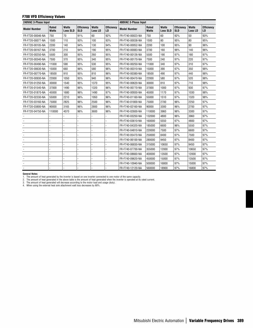
Mitsubishi Electric Automation | Variable Frequency Drives 389
240VAC 3-Phase Input 480VAC 3-Phase Input
Model Number Rated Watts
Watts Loss SLD
Efficiency SLD
Watts Loss LD
Efficiency LD Model Number Rated
WattsWatts Loss SLD
Efficiency SLD
Watts Loss LD
Efficiency LD
FR-F720-00046-NA 750 70 91% 60 92% FR-F740-00023-NA 750 60 92% 50 93%
FR-F720-00077-NA 1500 110 93% 100 93% FR-F740-00038-NA 1500 80 95% 80 95%
FR-F720-00105-NA 2200 140 94% 130 94% FR-F740-00052-NA 2200 100 95% 90 96%
FR-F720-00167-NA 3700 210 94% 190 95% FR-F740-00083-NA 3700 160 96% 140 96%
FR-F720-00250-NA 5500 300 95% 260 95% FR-F740-00126-NA 5500 190 97% 180 97%
FR-F720-00340-NA 7500 370 95% 340 95% FR-F740-00170-NA 7500 240 97% 220 97%
FR-F720-00490-NA 11000 590 95% 530 95% FR-F740-00250-NA 11000 340 97% 310 97%
FR-F720-00630-NA 15000 660 96% 580 96% FR-F740-00310-NA 15000 390 97% 350 98%
FR-F720-00770-NA 18500 910 95% 810 96% FR-F740-00380-NA 18500 490 97% 440 98%
FR-F720-00930-NA 22000 1050 95% 940 96% FR-F740-00470-NA 22000 580 97% 520 98%
FR-F720-01250-NA 30000 1540 95% 1370 95% FR-F740-00620-NA 30000 810 97% 710 98%
FR-F720-01540-NA 37000 1490 96% 1320 96% FR-F740-00770-NA 37000 1000 97% 930 97%
FR-F720-01870-NA 45000 1680 96% 1490 97% FR-F740-00930-NA 45000 1170 97% 1030 98%
FR-F720-02330-NA 55000 2210 96% 1950 96% FR-F740-01160-NA 55000 1510 97% 1320 98%
FR-F720-03160-NA 75000 2825 96% 2500 96% FR-F740-01800-NA 75000 2700 96% 2250 97%
FR-F720-03800-NA 90000 3165 96% 2800 96% FR-F740-02160-NA 90000 3300 96% 2700 97%
FR-F720-04750-NA 110000 4070 96% 3600 96% FR-F740-02600-NA 110000 3960 96% 3300 97%
- - - - - - FR-F740-03250-NA 132000 4800 96% 3960 97%
- - - - - - FR-F740-03610-NA 160000 5550 97% 4800 97%
- - - - - - FR-F740-04320-NA 185000 6600 96% 5550 97%
- - - - - - FR-F740-04810-NA 220000 7500 97% 6600 97%
- - - - - - FR-F740-05470-NA 250000 8400 97% 7500 97%
- - - - - - FR-F740-06100-NA 280000 9450 97% 8400 97%
- - - - - - FR-F740-06830-NA 315000 10650 97% 9450 97%
- - - - - - FR-F740-07700-NA 355000 12000 97% 10650 97%
- - - - - - FR-F740-08660-NA 400000 13500 97% 12000 97%
- - - - - - FR-F740-09620-NA 450000 15000 97% 13500 97%
- - - - - - FR-F740-10940-NA 500000 16800 97% 15000 97%
- - - - - - FR-F740-12120-NA 560000 18900 97% 16800 97%
F700 VFD Efficiency Values
General Notes:1. The amount of heat generated by the inverter is based on one inverter connected to one motor of the same capacity.2. The amount of heat generated in the above table is the amount of heat generated when the inverter is operated at its rated current.3. The amount of heat generated will decrease according to the motor load and usage (duty).4. When using the external heat sink attachment watt loss decreases by 60%.
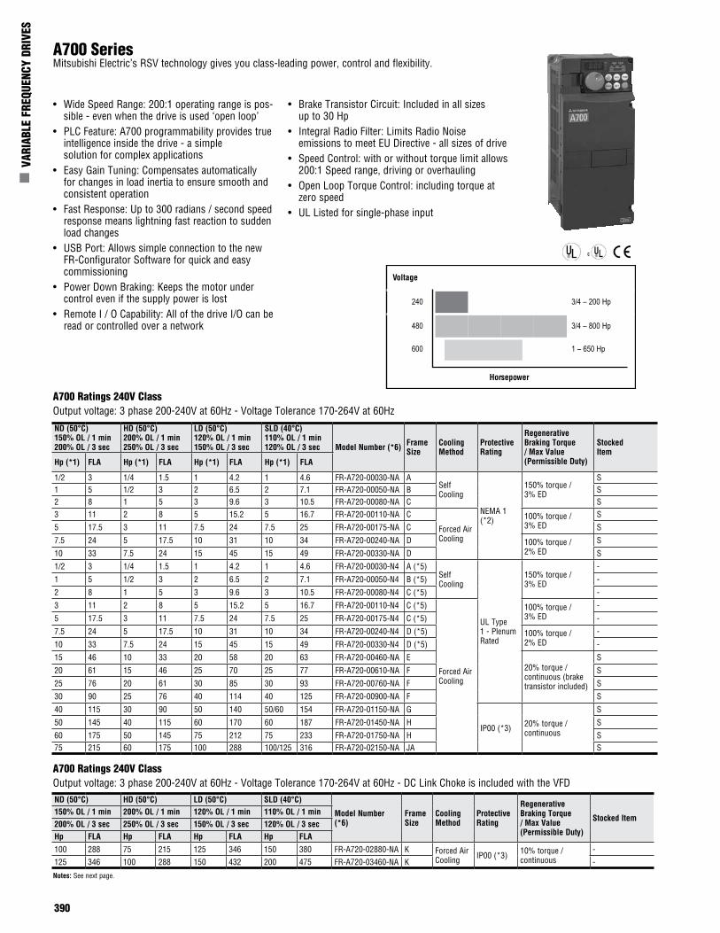
390
n V
ARIA
BLE
FREQ
UENC
Y DR
IVES
A700 SeriesMitsubishi Electric’s RSV technology gives you class-leading power, control and flexibility.
• Wide Speed Range: 200:1 operating range is pos-sible - even when the drive is used ‘open loop’
• PLC Feature: A700 programmability provides true intelligence inside the drive - a simple solution for complex applications
• Easy Gain Tuning: Compensates automatically for changes in load inertia to ensure smooth and consistent operation
• Fast Response: Up to 300 radians / second speed response means lightning fast reaction to sudden load changes
• USB Port: Allows simple connection to the new FR-Configurator Software for quick and easy commissioning
• Power Down Braking: Keeps the motor under control even if the supply power is lost
• Remote I / O Capability: All of the drive I/O can be read or controlled over a network
• Brake Transistor Circuit: Included in all sizes up to 30 Hp
• Integral Radio Filter: Limits Radio Noise emissions to meet EU Directive - all sizes of drive
• Speed Control: with or without torque limit allows 200:1 Speed range, driving or overhauling
• Open Loop Torque Control: including torque at zero speed
• UL Listed for single-phase input
A700 Ratings 240V Class Output voltage: 3 phase 200-240V at 60Hz - Voltage Tolerance 170-264V at 60Hz - DC Link Choke is included with the VFDND (50°C) HD (50°C) LD (50°C) SLD (40°C)
Model Number (*6)
Frame Size
Cooling Method
Protective Rating
Regenerative Braking Torque / Max Value (Permissible Duty)
Stocked Item150% OL / 1 min 200% OL / 1 min 120% OL / 1 min 110% OL / 1 min200% OL / 3 sec 250% OL / 3 sec 150% OL / 3 sec 120% OL / 3 secHp FLA Hp FLA Hp FLA Hp FLA
100 288 75 215 125 346 150 380 FR-A720-02880-NA K Forced Air Cooling IP00 (*3) 10% torque /
continuous -
125 346 100 288 150 432 200 475 FR-A720-03460-NA K -
Notes: See next page.
A700 Ratings 240V ClassOutput voltage: 3 phase 200-240V at 60Hz - Voltage Tolerance 170-264V at 60Hz
Voltage
240 3/4 – 200 Hp
480 3/4 – 800 Hp
600 1 – 650 Hp
Horsepower
ND (50°C)150% OL / 1 min200% OL / 3 sec
HD (50°C)200% OL / 1 min250% OL / 3 sec
LD (50°C)120% OL / 1 min150% OL / 3 sec
SLD (40°C)110% OL / 1 min120% OL / 3 sec Model Number (*6) Frame
SizeCooling Method
Protective Rating
Regenerative Braking Torque / Max Value (Permissible Duty)
Stocked Item
Hp (*1) FLA Hp (*1) FLA Hp (*1) FLA Hp (*1) FLA
1/2 3 1/4 1.5 1 4.2 1 4.6 FR-A720-00030-NA ASelf Cooling
NEMA 1 (*2)
150% torque / 3% ED
S1 5 1/2 3 2 6.5 2 7.1 FR-A720-00050-NA B S2 8 1 5 3 9.6 3 10.5 FR-A720-00080-NA C S3 11 2 8 5 15.2 5 16.7 FR-A720-00110-NA C
Forced Air Cooling
100% torque / 3% ED
S
5 17.5 3 11 7.5 24 7.5 25 FR-A720-00175-NA C S
7.5 24 5 17.5 10 31 10 34 FR-A720-00240-NA D 100% torque / 2% ED
S
10 33 7.5 24 15 45 15 49 FR-A720-00330-NA D S
1/2 3 1/4 1.5 1 4.2 1 4.6 FR-A720-00030-N4 A (*5)Self Cooling
UL Type 1 - Plenum Rated
150% torque / 3% ED
-
1 5 1/2 3 2 6.5 2 7.1 FR-A720-00050-N4 B (*5) -
2 8 1 5 3 9.6 3 10.5 FR-A720-00080-N4 C (*5) -
3 11 2 8 5 15.2 5 16.7 FR-A720-00110-N4 C (*5)
Forced Air Cooling
100% torque / 3% ED
-
5 17.5 3 11 7.5 24 7.5 25 FR-A720-00175-N4 C (*5) -
7.5 24 5 17.5 10 31 10 34 FR-A720-00240-N4 D (*5) 100% torque / 2% ED
-
10 33 7.5 24 15 45 15 49 FR-A720-00330-N4 D (*5) -
15 46 10 33 20 58 20 63 FR-A720-00460-NA E20% torque / continuous (brake transistor included)
S
20 61 15 46 25 70 25 77 FR-A720-00610-NA F S
25 76 20 61 30 85 30 93 FR-A720-00760-NA F S
30 90 25 76 40 114 40 125 FR-A720-00900-NA F S
40 115 30 90 50 140 50/60 154 FR-A720-01150-NA G
IP00 (*3) 20% torque / continuous
S
50 145 40 115 60 170 60 187 FR-A720-01450-NA H S
60 175 50 145 75 212 75 233 FR-A720-01750-NA H S75 215 60 175 100 288 100/125 316 FR-A720-02150-NA JA S
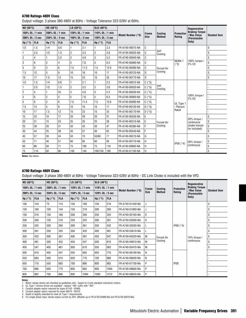
Mitsubishi Electric Automation | Variable Frequency Drives 391
A700 Ratings 480V ClassOutput voltage: 3 phase 380-480V at 60Hz - Voltage Tolerance 323-528V at 60Hz.
A700 Ratings 480V ClassOutput voltage: 3 phase 380-480V at 60Hz - Voltage Tolerance 323-528V at 60Hz - DC Link Choke is included with the VFD.
ND (50°C) HD (50°C) LD (50°C) SLD (40°C)
Model Number (*6) Frame Size
Cooling Method
Protective Rating
Regenerative Braking Torque / Max Value (Permissible Duty)
Stocked Item150% OL / 1 min 200% OL / 1 min 120% OL / 1 min 110% OL / 1 min
200% OL / 3 sec 250% OL / 3 sec 150% OL / 3 sec 120% OL / 3 sec
Hp (*1) FLA Hp (*1) FLA Hp (*1) FLA Hp (*1) FLA
100 144 75 110 150 180 150 216 FR-A740-01440-NA J
Forced Air Cooling
IP00 (*4)
10% torque / continuous
S
150 180 100 144 150 216 200 260 FR-A740-01800-NA J S
150 216 150 180 200 260 250 325 FR-A740-02160-NA K S
200 260 150 216 250 325 300 361 FR-A740-02600-NA K S
250 325 200 260 300 361 350 432 FR-A740-03250-NA L S
300 361 250 325 350 432 400 481 FR-A740-03610-NA L S
350 432 300 361 400 481 450 547 FR-A740-04320-NA M S
400 481 350 432 450 547 500 610 FR-A740-04810-NA M S
450 547 400 481 500 610 550 683 FR-A740-05470-NA M S
500 610 450 547 550 683 650 770 FR-A740-06100-NA N
IP00
-
550 683 500 610 650 770 700 866 FR-A740-06830-NA N -
650 770 550 683 700 866 800 962 FR-A740-07700-NA P -
700 866 650 770 800 962 900 1094 FR-A740-08660-NA P -
800 962 700 866 900 1094 1000 1212 FR-A740-09620-NA P -
Notes:1. Motor ratings shown are intended as guidelines only - based on 4 pole standard inductions motors.2. UL Type 1 version drives are available - replace “-NA” suffix with “-N4”.3. Conduit adapter option required for types 01150 - 03460. 4. Conduit adapter option required for types 00570 - 05470. 5. Depth is slightly extended to meet UL Type 1 requirements.6. For single phase input, derate output current by 40% (Models up to FR-A720-02880-NA and FR-A740-03610-NA)
Notes: See below.
ND (50°C) HD (50°C) LD (50°C) SLD (40°C)
Model Number (*6) Frame Size
Cooling Method
Protective Rating
Regenerative Braking Torque / Max Value (Permissible Duty)
Stocked Item150% OL / 1 min 200% OL / 1 min 120% OL / 1 min 110% OL / 1 min
200% OL / 3 sec 250% OL / 3 sec 150% OL / 3 sec 120% OL / 3 sec
Hp (*1) FLA Hp (*1) FLA Hp (*1) FLA Hp (*1) FLA
1/2 1.5 1/4 0.8 1 2.1 1 2.3 FR-A740-00015-NA CSelf Cooling
NEMA 1 (*2)
100% torque / 2% ED
S
1 2.5 1/2 1.5 2 3.5 2 3.8 FR-A740-00025-NA C S
2 4 1 2.5 3 4.8 3 5.2 FR-A740-00040-NA C S
3 6 2 4 5 7.6 5 8.3 FR-A740-00060-NA C
Forced Air Cooling
S
5 9 3 6 7.5 11.5 7.5 12.6 FR-A740-00090-NA C S
7.5 12 5 9 10 16 10 17 FR-A740-00120-NA D S
10 17 7.5 12 15 23 15 25 FR-A740-00170-NA D S
1/2 1.5 1/4 0.8 1 2.1 1 2.3 FR-A740-00015-N4 C (*5)Self Cooling
UL Type 1 - Plenum Rated
100% torque / 2% ED
-
1 2.5 1/2 1.5 2 3.5 2 3.8 FR-A740-00025-N4 C (*5) -
2 4 1 25 3 4.8 3 5.2 FR-A740-00040-N4 C (*5) -
3 6 2 4 5 7.6 5 8.3 FR-A740-00060-N4 C (*5)
Forced Air Cooling
-
5 9 3 6 7.5 11.5 7.5 12.6 FR-A740-00090-N4 C (*5) -
7.5 12 5 9 10 16 10 17 FR-A740-00120-N4 D (*5) -
10 17 7.5 12 15 23 15 25 FR-A740-00170-N4 D (*5) -
15 23 10 17 20 29 20 31 FR-A740-00230-NA E20% torque / continuous (brake transis-tor included)
S
20 31 15 23 25 35 25 38 FR-A740-00310-NA E S
25 38 20 31 30 43 30 47 FR-A740-00380-NA F S
30 44 25 38 40 57 40 62 FR-A740-00440-NA F S
40 57 30 44 50 70 50/60 77 FR-A740-00570-NA G
IP00 (*4) 20% torque / continuous
S
50 71 40 57 60 85 60 93 FR-A740-00710-NA H S
60 86 50 71 75 106 75 116 FR-A740-00860-NA H S
75 110 60 86 100 144 100/150 180 FR-A740-01100-NA H S
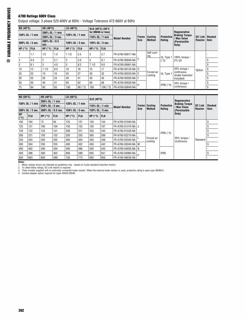
392
n V
ARIA
BLE
FREQ
UENC
Y DR
IVES
A700 Ratings 600V ClassOutput voltage: 3 phase 525-600V at 60Hz - Voltage Tolerance 472-660V at 60Hz
Notes:1. Motor ratings shown are intended as guidelines only - based on 4 pole standard induction motors.2. To utilize these ratings, DC Link reactor is required.3. These models supplied with an externally connected brake resistor. When the external brake resistor is used, protective rating is open type (NEMA1).4. Conduit adapter option required for types 00550-03040.
ND (40°C) HD (40°C) LD (40°C) SLD (40°C) (30°C for 00040 or less)
Model Number Frame Size
Cooling Method
Protective Rating
Regenerative Braking Torque / Max Value (Permissible Duty)
DC Link Reactor
Stocked Item
150% OL / 1 min200% OL / 1 min
120% OL / 1 min250% OL / 3 sec. 110% OL / 1 min
200% OL / 3 sec. 280% OL / 0.5 sec. 150% OL / 3 sec. 120% OL / 3 sec.
HP (*1) FLA HP (*1) FLA HP (*1) FLA HP (*1) FLA
1 1.7 1/2 1.0 1 1/2 2.5 2 2.7 FR-A760-00017-NA
C
Self cool-ing UL Type 1
(*3)100% torque / 2% ED
Option
-
3 4.0 2 2.7 3 5.6 5 6.1 FR-A760-00040-NA
Forced air cooling
S
5 6.1 3 4.0 5 8.2 7 1/2 9.0 FR-A760-00061-NA S
10 12 7 1/2 9.0 10 16 15 17 FR-A760-00120-NA D
UL Type 1
20% torque / continuous (brake transistor included)
S
20 22 10 16 25 27 30 32 FR-A760-00220-NA E S
30 33 20 24 40 41 40 45 FR-A760-00330-NA F S
50 55 40 41 60 62 60 68 FR-A760-00550-NAH IP00 (*4) 20% torque /
continuousS
75 84 60 63 100 99 (*2) 100 108 (*2) FR-A760-00840-NA S
ND (50°C) HD (40°C) LD (50°C)SLD (40°C)
Model Number Frame Size
Cooling Method
Protective Rating
Regenerative Braking Torque / Max Value (Permissible Duty)
DC Link Reactor
Stocked Item
150% OL / 1 min200% OL / 1 min
120% OL / 1 min250% OL / 3 sec. 110% OL / 1 min
200% OL / 3 sec. 280% OL / 0.5 sec. 150% OL / 3 sec. 120% OL / 3 sec.HP (*1) FLA HP (*1) FLA HP (*1) FLA HP (*1) FLA
100 104 75 84 125 131 150 144 FR-A760-01040-NA
J
Forced air cooling
IP00 (*4)
20% torque / continuous Standard
S
125 131 100 104 150 152 150 167 FR-A760-01310-NA S
150 152 125 131 200 221 250 243 FR-A760-01520-NA S
200 221 150 152 250 255 300 289 FR-A760-02210-NAL
S
250 255 200 202 300 304 350 336 FR-A760-02550-NA -
300 304 250 255 400 402 450 442 FR-A760-03040-NA M S
400 402 300 304 500 496 550 545 FR-A760-04020-NA N
IP00
-
500 496 400 402 600 589 650 647 FR-A760-04960-NA P
S
650 663 600 589 750 773 850 850 FR-A760-06630-NA -
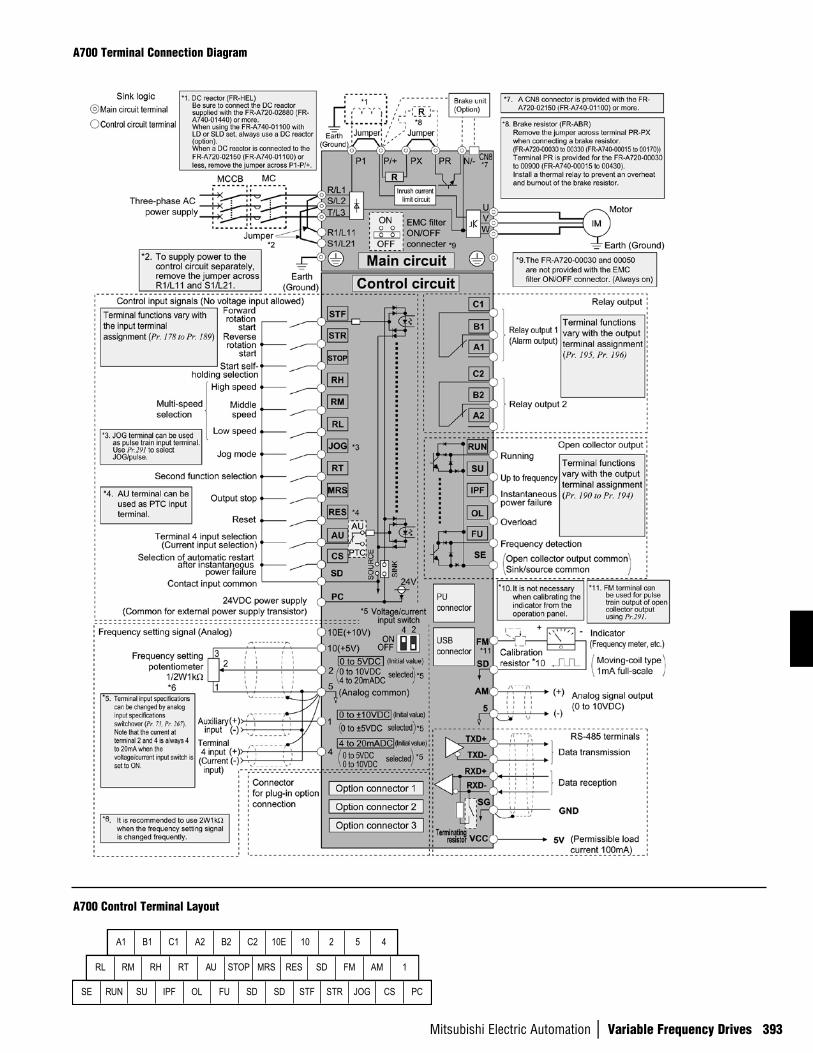
Mitsubishi Electric Automation | Variable Frequency Drives 393
A700 Terminal Connection Diagram
A700 Control Terminal Layout
A1 B1 C1 A2 B2 C2 10E 10 2 5 4
RL RM RH RT AU STOP MRS RES SD FM AM 1
SE RUN SU IPF OL FU SD SD STF STR JOG CS PC
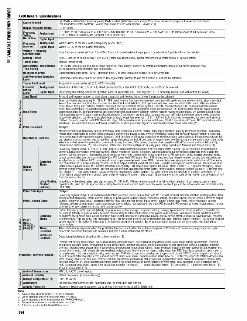
394
n V
ARIA
BLE
FREQ
UENC
Y DR
IVES
A700 General Specifications
Notes:1. Available only when the option (FR-A7AP) is mounted2. Can be displayed only on the operation panel (FR-DU07).3. Can be displayed only on the parameter unit (FR-PU07/FR-PU04).4. Temperature applicable for a short period in transit, etc.5. 2.9m/s2 or less for the FR-A740-03250 or more.
Oper
atio
n Sp
ecifi
catio
nsControl Method Soft-PWM control/high carrier frequency PWM control (selectable from among V/F control, advanced magnetic flux vector control and
real sensorless vector control) / vector control (when used with option FR-A7AP) (*1)Output Frequency Range 0.2 to 400Hz
Frequency Setting Resolution
Analog Input 0.015Hz/0 to 60Hz (terminal 2, 4: 0 to 10V/12 bit); 0.03Hz/0 to 60Hz (terminal 2, 4: 0 to 5V/11 bit, 0 to 20mA/about 11 bit, terminal 1: 0 to ±10V/12 bit) 0.06Hz/0 to 60Hz (terminal 1: 0 to ±5V/11 bit)
Digital Input 0.01Hz Frequency Accuracy
Analog Input Within ±0.2% of the max. output frequency (25°C ±10°C) Digital Input Within 0.01% of the set output frequency
Voltage / Frequency Characteristics Base frequency can be set from 0 to 400Hz Constant torque/variable torque pattern or adjustable 5 points V/F can be selected
Starting Torque 200% 0.3Hz (up to frame size C), 150% 0.3Hz (Frame Size D and above) (under real sensorless vector control or vector control) Torque Boost Manual torque boost Acceleration / Deceleration Time Setting
0 to 3600s (acceleration and deceleration can be set individually), linear or S-pattern acceleration/deceleration mode, backlash mea-sures acceleration/deceleration can be selected.
DC Injection Brake Operation frequency (0 to 120Hz), operation time (0 to 10s), operation voltage (0 to 30%) variable Stall Prevention Operation Level Operation current level can be set (0 to 220% adjustable), whether to use the function or not can be selected
Torque Limit Level Torque limit value can be set (0 to 400% variable) Frequency Setting Signal
Analog Input Terminal 2: 4: 0 to 10V, 0 to 5V, 4 to 20mA can be selected • Terminal 1:-10 to +10V, -5 to +5V can be selected
Digital Input Input using the setting dial of the operation panel or parameter unit. Four-digit BCD or 16 bit binary (when used with option FR-A7AX)
Start Signal Forward and reverse rotation or start signal automatic self-holding input (3-wire input) can be selected.
Input Signal
Select any twelve signals using Pr. 178 to Pr. 189 (input terminal function selection) from among multi speed selection, remote setting, stop-on-contact, second function selection, third function selection, terminal 4 input selection, JOG operation selection, selection of automatic restart after instantaneous power failure, flying start, external thermal relay input, inverter operation enable signal (FR-HC/FR-CV connection), FR-HC connection (instantaneous power failure detection), PU operation/external inter lock signal, external DC injection brake operation start, PID control enable terminal, brake opening completion signal, PU operation/external operation switchover, load pattern selection forward rotation reverse rotation boost, V/F switching, load torque high-speed frequency, S-pattern acceleration/deceleration C switchover, pre-excitation, output stop, start self-holding selection, control mode changing, torque limit selection, start-time tuning start external input, torque bias selection 1, 2 (*1), P/PI control switchover, forward rotation command, reverse rotation command, inverter reset, PTC thermistor input, PID forward reverse operation switchover, PU-NET operation switchover, NET-external operation switchover, and command source switchover, conditional position pulse train sign (*1), conditional position droop pulse clear (*1).
Pulse Train Input 100kpps
Operational Functions
Maximum/minimum frequency setting, frequency jump operation, external thermal relay input selection, polarity reversible operation, automatic restart after instantaneous power failure operation, commercial power supply-inverter switchover operation, forward/reverse rotation prevention, remote setting, brake sequence, second function, third function, multi-speed operation, original operation continuation at instantaneous power fail-ure, stop-on-contact control, load torque high speed frequency control, droop control, regeneration avoidance, slip compensation, operation mode selection, offline auto tuning function, online auto tuning function, PID control, computer link operation (RS-485), motor end orientation (*1), machine end orientation (*1), pre-excitation, notch filter, machine analyzer (*1), easy gain tuning, speed feed forward, and torque bias (*1)
Output Signals
Operating Status
Select any signals using Pr. 190 to Pr. 196 (output terminal function selection) from among inverter running, up-to-frequency, instantaneous power failure/undervoltage, overload warning, output frequency (speed) detection, second output frequency (speed) detection, third output fre-quency (speed) detection, regenerative brake prealarm, electronic thermal relay function pre-alarm, PU operation mode, inverter operation ready, output current detection, zero current detection, PID lower limit, PID upper limit, PID forward rotation reverse rotation output, commercial power supply-inverter switchover MC1, commercial power supply-inverter switchover MC2, commercial power supply-inverter switchover MC3, orienta-tion completion (*1), brake opening request, fan fault output, heatsink overheat pre-alarm , inverter running/start command on, deceleration at an instantaneous power failure, PID control activated, during retry, PID output interruption, life alarm, alarm output 1, 2, 3 (power-off signal), power savings average value update timing, current average monitor, maintenance timer alarm, remote output, forward rotation output (*1), reverse rota-tion output (*1), low speed output, torque detection, regenerative status output (*1), start-time tuning completion, in-position completion (*1), minor failure output and alarm output. Open collector output (5 points), relay output (2 points) and alarm code of the inverter can be output (4 bit) from the open collector.
Using FR-A7AY, FR-A7AR (optional)
In addition to the above, select any signals using Pr. 313 to Pr. 319 (extension output terminal function selection) from among control circuit capacitor life, main circuit capacitor life, cooling fan life, inrush current limit circuit life (only positive logic can be set for extension terminals of the FR-A7AR).
Pulse Train Input 500kpps
Pulse / Analog Output
Select any signals using Pr. 54 FM terminal function selection (pulse train output) and Pr. 158 AM terminal function selection (analog output) from among output frequency, motor current (steady or peak value), output voltage, frequency setting, operation speed, motor torque, converter output voltage (steady or peak value), electronic thermal relay function load factor, input power, output power, load meter, motor excitation current, reference voltage output, motor load factor, power saving effect, regenerative brake duty, PID set point, PID measured value, motor output, torque command, torque current command, and torque monitor.
Indi
catio
n PU (FR-DU07 / FR-PU07 / FR-PU04)
Operating Status
Output frequency, motor current (steady or peak value), output voltage, frequency setting, running speed,motor torque, overload, converter out-put voltage (steady or peak value), electronic thermal relay function load factor, input power, output power, load meter, motor excitation current, cumulative energization time, actual operation time, motor load factor, cumulative power, energy saving effect, cumulative saving power, regenera-tive brake duty, PID set point, PID measured value, PID deviation, inverter I/O terminal monitor, input terminal option monitor (*2), output terminal option monitor (*2), option fitting status (*3), terminal assignment status (*3), torque command, torque current command, feed back pulse (*1), motor output
Alarm Definition
Alarm definition is displayed when the protective function is activated, the output voltage/current/frequency/cumulative energization time right before the protection function was activated and past 8 alarm definitions are stored.
Interactive Guidance Operation guide/trouble shooting with a help function (*3)
Protective / Warning Function
Overcurrent during acceleration, overcurrent during constant speed, overcurrent during deceleration, overvoltage during acceleration, overvolt-age during constant speed, overvoltage during deceleration, inverter protection thermal operation, motor protection thermal operation, heatsink overheat, instantaneous power failure occurrence, undervoltage, input phase failure, motor overload, output side earth (ground) fault overcurrent, output short circuit, main circuit element overheat, output phase failure, external thermal relay operation, PTC thermistor operation, option alarm, parameter error, PU disconnection, retry count excess, CPU alarm, operation panel power supply short circuit, 24VDC power output short circuit, output current detection value excess, inrush current limit circuit alarm, communication alarm (inverter), USB error, opposite rotation deceleration error, analog input error, fan fault, overcurrent stall prevention, overvoltage stall prevention, regenerative brake prealarm, electronic thermal relay function prealarm, PU stop, maintenance timer alarm (*2), brake transistor alarm, parameter write error, copy operation error, operation panel lock, parameter copy alarm, speed limit indication, encoder no-signal (*1), speed deviation large (*1), overspeed (*1), position error large (*1), encoder phase error (*1)
Envi
ronm
ent Ambient Temperature -10°C to +50°C (non-freezing)
Ambient Humidity 90%RH maximum (non-condensing)Storage Temperature (*4) -20°C to +65°CAtmosphere Indoors (without corrosive gas, flammable gas, oil mist, dust and dirt etc.)Altitude / Vibration Maximum 1000m above sea level, 0.6 G or less (*5) (conforms to JIS C 60068-2-6)
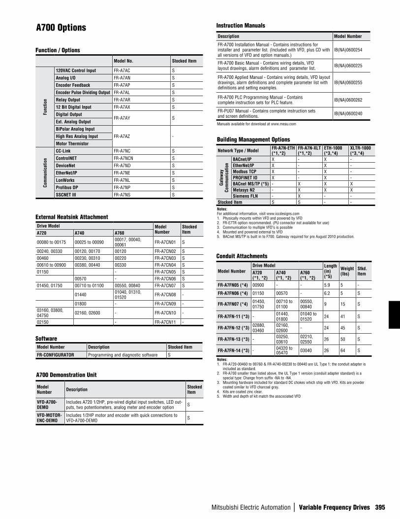
Mitsubishi Electric Automation | Variable Frequency Drives 395
A700 Options
External Heatsink Attachment
Conduit Attachments
Drive Model Model Number
Stocked ItemA720 A740 A760
00080 to 00175 00025 to 00090 00017, 00040, 00061 FR-A7CN01 S
00240, 00330 00120, 00170 00120 FR-A7CN02 S00460 00230, 00310 00220 FR-A7CN03 S00610 to 00900 00380, 00440 00330 FR-A7CN04 S01150 - FR-A7CN05 S
00570 - FR-A7CN06 S01450, 01750 00710 to 01100 00550, 00840 FR-A7CN07 S
01440 01040, 01310, 01520 FR-A7CN08 -
01800 - FR-A7CN09 -03160, 03800, 04750 02160, 02600 - FR-A7CN10 -
02150 - FR-A7CN11 -
Manuals available for download at www.meau.com
Description Model Number
FR-A700 Installation Manual - Contains instructions for installer and parameter list. (Included with VFD, plus CD with all versions of VFD and option manuals.)
IB(NA)0600254
FR-A700 Basic Manual - Contains wiring details, VFD layout drawings, alarm definitions and parameter list. IB(NA)0600225
FR-A700 Applied Manual - Contains wiring details, VFD layout drawings, alarm definitions and complete parameter list with definitions and setting examples.
IB(NA)0600255
FR-A700 PLC Programming Manual - Contains complete instruction sets for PLC feature. IB(NA)0600262
FR-PU07 Manual - Contains complete instruction sets and screen definitions. IB(NA)0600240
Function / Options
SoftwareModel Number Description Stocked Item
FR-CONFIGURATOR Programming and diagnostic software S
Model No. Stocked Item
Func
tion
120VAC Control Input FR-A7AC S
Analog I/O FR-A7AN S
Encoder Feedback FR-A7AP S
Encoder Pulse Dividing Output FR-A7AL S
Relay Output FR-A7AR S
12 Bit Digital Input FR-A7AX S
Digital Output FR-A7AY S
Ext. Analog Output
BiPolar Analog Input
FR-A7AZ -High Res Analog Input
Motor Thermistor
Com
mun
icat
ion
CC-Link FR-A7NC S
ControlNET FR-A7NCN S
DeviceNet FR-A7ND S
EtherNet/IP FR-A7NE S
LonWorks FR-A7NL S
Profibus DP FR-A7NP S
SSCNET III FR-A7NS S
Instruction Manuals
Notes:1. FR-A720-00460 to 00760 & FR-A740-00230 to 00440 are UL Type 1: the conduit adapter is
included as standard.2. FR-A700 smaller than listed above, the UL Type 1 version (conduit adapter standard) is a
special type: Change from suffix -NA to -N4.3. Mounting hardware included for standard DC chokes which ship with VFD. Kits are powder
coated similar to VFD charcoal gray.4. Kits are coated zinc clear.5. Width and depth of kit match the asscociated VFD
Model Number Description Stocked
Item
VFD-A700-DEMO
Includes A720 1/2HP, pre-wired digital input switches, LED out-puts, two potentiometers, analog meter and encoder option S
VFD-MOTOR-ENC-DEMO
Includes 1/2HP motor and encoder with quick connections to VFD-A700-DEMO S
A700 Demonstration Unit
Model NumberDrive Model Length
(in) (*5)
Weight (lbs)
Stkd. ItemA720
(*1, *2)A740 (*1, *2)
A760 (*1, *2)
FR-A7FN05 (*4) 00900 - - 5.9 5 -
FR-A7FN06 (*4) 01150 00570 - 6.2 5 S
FR-A7FN07 (*4) 01450, 01750
00710 to 01100
00550, 00840 9 15 S
FR-A7FN-11 (*3) - 01440, 01800
01040 to 01520 24 41 S
FR-A7FN-12 (*3) 02880, 03460
02160, 02600 - 24 45 S
FR-A7FN-13 (*3) - 03250, 03610
02210, 02550 26 50 S
FR-A7FN-14 (*3) - 04320 to 05470 03040 26 64 S
Building Management Options
Notes:For additional information, visit www.iccdesigns.com1. Physically mounts within VFD and powered by VFD2. FR-E7TR option recommended. (PU connector not available for use)3. Communication to multiple VFD’s is possible4. Mounted and powered external to VFD5. BACnet MS/TP is built in to F700. Gateway required for pre August 2010 production.
Network Type / Model FR-A7N-ETH (*1,*2)
FR-A7N-XLT (*1,*2)
ETH-1000(*3,*4)
XLTR-1000(*3,*4)
Gate
way
Co
mm
unic
atio
n
BACnet/IP X - X -EtherNet/IP X - X -Modbus TCP X - X -PROFINET IO X - X -BACnet MS/TP (*5) - X X XMetasys N2 - X X XSiemens FLN - X - -
Stocked Item S S - -
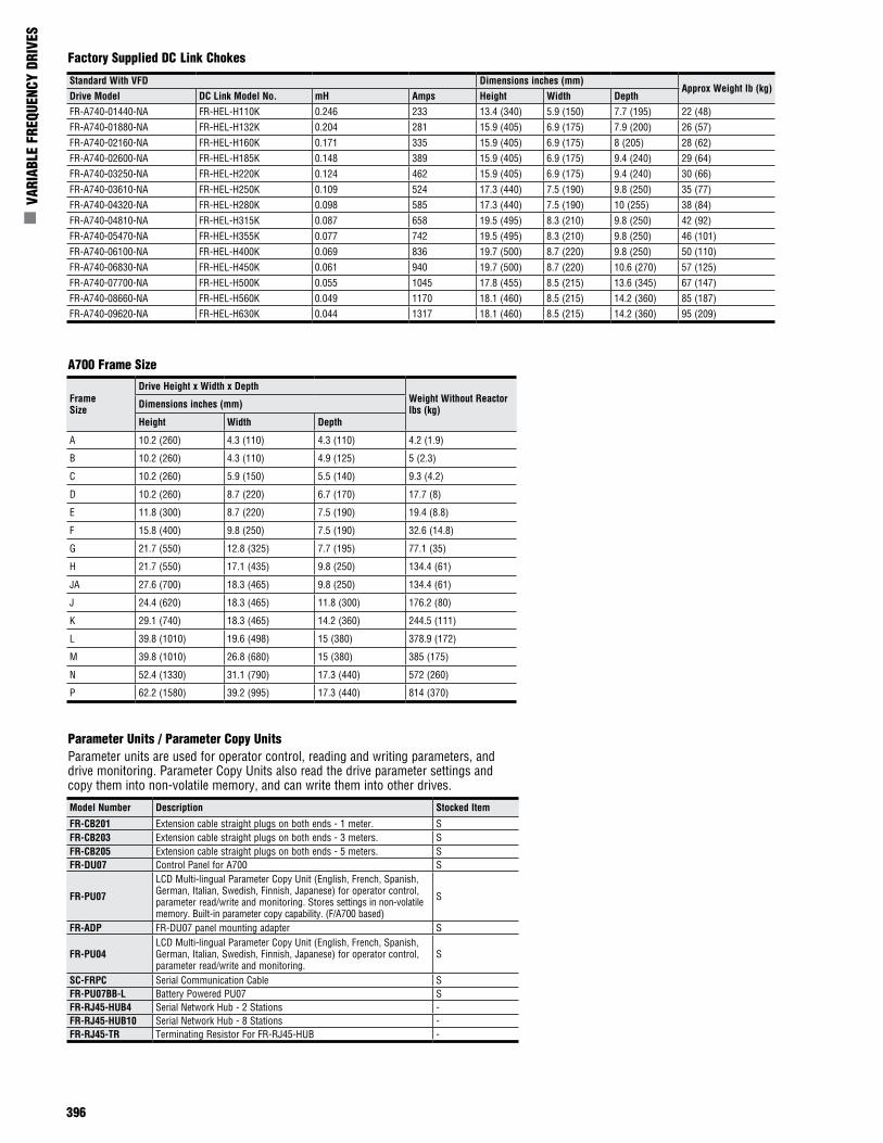
396
n V
ARIA
BLE
FREQ
UENC
Y DR
IVES
Model Number Description Stocked Item
FR-CB201 Extension cable straight plugs on both ends - 1 meter. SFR-CB203 Extension cable straight plugs on both ends - 3 meters. SFR-CB205 Extension cable straight plugs on both ends - 5 meters. SFR-DU07 Control Panel for A700 S
FR-PU07
LCD Multi-lingual Parameter Copy Unit (English, French, Spanish, German, Italian, Swedish, Finnish, Japanese) for operator control, parameter read/write and monitoring. Stores settings in non-volatile memory. Built-in parameter copy capability. (F/A700 based)
S
FR-ADP FR-DU07 panel mounting adapter S
FR-PU04LCD Multi-lingual Parameter Copy Unit (English, French, Spanish, German, Italian, Swedish, Finnish, Japanese) for operator control, parameter read/write and monitoring.
S
SC-FRPC Serial Communication Cable SFR-PU07BB-L Battery Powered PU07 SFR-RJ45-HUB4 Serial Network Hub - 2 Stations -FR-RJ45-HUB10 Serial Network Hub - 8 Stations -FR-RJ45-TR Terminating Resistor For FR-RJ45-HUB -
A700 Frame Size
Frame Size
Drive Height x Width x Depth Weight Without Reactor lbs (kg)Dimensions inches (mm)
Height Width Depth
A 10.2 (260) 4.3 (110) 4.3 (110) 4.2 (1.9)
B 10.2 (260) 4.3 (110) 4.9 (125) 5 (2.3)
C 10.2 (260) 5.9 (150) 5.5 (140) 9.3 (4.2)
D 10.2 (260) 8.7 (220) 6.7 (170) 17.7 (8)
E 11.8 (300) 8.7 (220) 7.5 (190) 19.4 (8.8)
F 15.8 (400) 9.8 (250) 7.5 (190) 32.6 (14.8)
G 21.7 (550) 12.8 (325) 7.7 (195) 77.1 (35)
H 21.7 (550) 17.1 (435) 9.8 (250) 134.4 (61)
JA 27.6 (700) 18.3 (465) 9.8 (250) 134.4 (61)
J 24.4 (620) 18.3 (465) 11.8 (300) 176.2 (80)
K 29.1 (740) 18.3 (465) 14.2 (360) 244.5 (111)
L 39.8 (1010) 19.6 (498) 15 (380) 378.9 (172)
M 39.8 (1010) 26.8 (680) 15 (380) 385 (175)
N 52.4 (1330) 31.1 (790) 17.3 (440) 572 (260)
P 62.2 (1580) 39.2 (995) 17.3 (440) 814 (370)
Factory Supplied DC Link Chokes
Parameter Units / Parameter Copy UnitsParameter units are used for operator control, reading and writing parameters, and drive monitoring. Parameter Copy Units also read the drive parameter settings and copy them into non-volatile memory, and can write them into other drives.
Standard With VFD Dimensions inches (mm)Approx Weight lb (kg)
Drive Model DC Link Model No. mH Amps Height Width DepthFR-A740-01440-NA FR-HEL-H110K 0.246 233 13.4 (340) 5.9 (150) 7.7 (195) 22 (48)FR-A740-01880-NA FR-HEL-H132K 0.204 281 15.9 (405) 6.9 (175) 7.9 (200) 26 (57)FR-A740-02160-NA FR-HEL-H160K 0.171 335 15.9 (405) 6.9 (175) 8 (205) 28 (62)FR-A740-02600-NA FR-HEL-H185K 0.148 389 15.9 (405) 6.9 (175) 9.4 (240) 29 (64)FR-A740-03250-NA FR-HEL-H220K 0.124 462 15.9 (405) 6.9 (175) 9.4 (240) 30 (66)FR-A740-03610-NA FR-HEL-H250K 0.109 524 17.3 (440) 7.5 (190) 9.8 (250) 35 (77)FR-A740-04320-NA FR-HEL-H280K 0.098 585 17.3 (440) 7.5 (190) 10 (255) 38 (84)FR-A740-04810-NA FR-HEL-H315K 0.087 658 19.5 (495) 8.3 (210) 9.8 (250) 42 (92)FR-A740-05470-NA FR-HEL-H355K 0.077 742 19.5 (495) 8.3 (210) 9.8 (250) 46 (101)FR-A740-06100-NA FR-HEL-H400K 0.069 836 19.7 (500) 8.7 (220) 9.8 (250) 50 (110)FR-A740-06830-NA FR-HEL-H450K 0.061 940 19.7 (500) 8.7 (220) 10.6 (270) 57 (125)FR-A740-07700-NA FR-HEL-H500K 0.055 1045 17.8 (455) 8.5 (215) 13.6 (345) 67 (147)FR-A740-08660-NA FR-HEL-H560K 0.049 1170 18.1 (460) 8.5 (215) 14.2 (360) 85 (187)FR-A740-09620-NA FR-HEL-H630K 0.044 1317 18.1 (460) 8.5 (215) 14.2 (360) 95 (209)
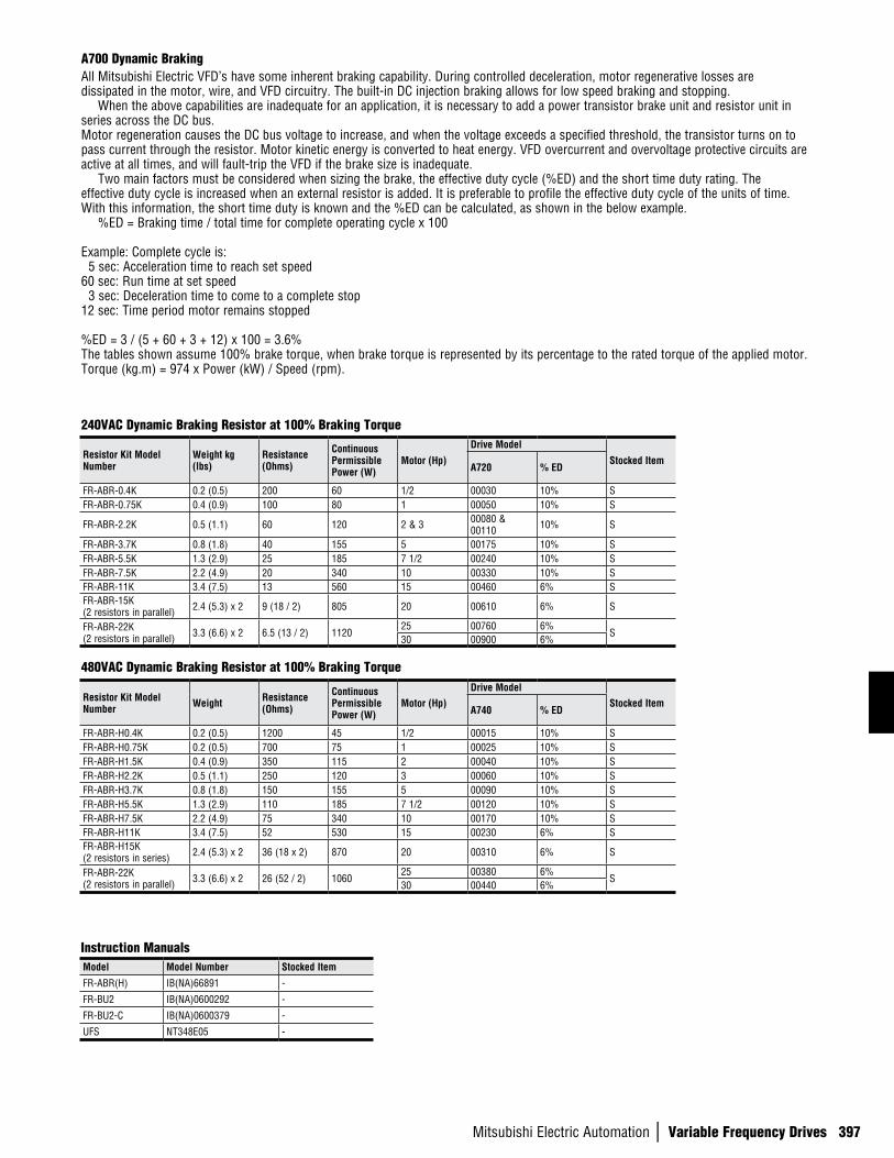
Mitsubishi Electric Automation | Variable Frequency Drives 397
A700 Dynamic BrakingAll Mitsubishi Electric VFD’s have some inherent braking capability. During controlled deceleration, motor regenerative losses are dissipated in the motor, wire, and VFD circuitry. The built-in DC injection braking allows for low speed braking and stopping. When the above capabilities are inadequate for an application, it is necessary to add a power transistor brake unit and resistor unit in series across the DC bus. Motor regeneration causes the DC bus voltage to increase, and when the voltage exceeds a specified threshold, the transistor turns on to pass current through the resistor. Motor kinetic energy is converted to heat energy. VFD overcurrent and overvoltage protective circuits are active at all times, and will fault-trip the VFD if the brake size is inadequate. Two main factors must be considered when sizing the brake, the effective duty cycle (%ED) and the short time duty rating. The effective duty cycle is increased when an external resistor is added. It is preferable to profile the effective duty cycle of the units of time. With this information, the short time duty is known and the %ED can be calculated, as shown in the below example. %ED = Braking time / total time for complete operating cycle x 100
Example: Complete cycle is: 5 sec: Acceleration time to reach set speed60 sec: Run time at set speed 3 sec: Deceleration time to come to a complete stop12 sec: Time period motor remains stopped
%ED = 3 / (5 + 60 + 3 + 12) x 100 = 3.6%The tables shown assume 100% brake torque, when brake torque is represented by its percentage to the rated torque of the applied motor.Torque (kg.m) = 974 x Power (kW) / Speed (rpm).
Model Model Number Stocked Item
FR-ABR(H) IB(NA)66891 -
FR-BU2 IB(NA)0600292 -
FR-BU2-C IB(NA)0600379 -
UFS NT348E05 -
240VAC Dynamic Braking Resistor at 100% Braking Torque
480VAC Dynamic Braking Resistor at 100% Braking Torque
Instruction Manuals
Resistor Kit Model Number
Weight kg (lbs)
Resistance (Ohms)
Continuous Permissible Power (W)
Motor (Hp)
Drive Model
Stocked ItemA720 % ED
FR-ABR-0.4K 0.2 (0.5) 200 60 1/2 00030 10% SFR-ABR-0.75K 0.4 (0.9) 100 80 1 00050 10% S
FR-ABR-2.2K 0.5 (1.1) 60 120 2 & 3 00080 & 00110 10% S
FR-ABR-3.7K 0.8 (1.8) 40 155 5 00175 10% SFR-ABR-5.5K 1.3 (2.9) 25 185 7 1/2 00240 10% SFR-ABR-7.5K 2.2 (4.9) 20 340 10 00330 10% SFR-ABR-11K 3.4 (7.5) 13 560 15 00460 6% SFR-ABR-15K (2 resistors in parallel) 2.4 (5.3) x 2 9 (18 / 2) 805 20 00610 6% S
FR-ABR-22K (2 resistors in parallel) 3.3 (6.6) x 2 6.5 (13 / 2) 1120
25 00760 6%S
30 00900 6%
Resistor Kit Model Number Weight Resistance
(Ohms)
Continuous Permissible Power (W)
Motor (Hp)Drive Model
Stocked ItemA740 % ED
FR-ABR-H0.4K 0.2 (0.5) 1200 45 1/2 00015 10% SFR-ABR-H0.75K 0.2 (0.5) 700 75 1 00025 10% SFR-ABR-H1.5K 0.4 (0.9) 350 115 2 00040 10% SFR-ABR-H2.2K 0.5 (1.1) 250 120 3 00060 10% SFR-ABR-H3.7K 0.8 (1.8) 150 155 5 00090 10% SFR-ABR-H5.5K 1.3 (2.9) 110 185 7 1/2 00120 10% SFR-ABR-H7.5K 2.2 (4.9) 75 340 10 00170 10% SFR-ABR-H11K 3.4 (7.5) 52 530 15 00230 6% SFR-ABR-H15K (2 resistors in series) 2.4 (5.3) x 2 36 (18 x 2) 870 20 00310 6% S
FR-ABR-22K (2 resistors in parallel) 3.3 (6.6) x 2 26 (52 / 2) 1060
25 00380 6%S
30 00440 6%
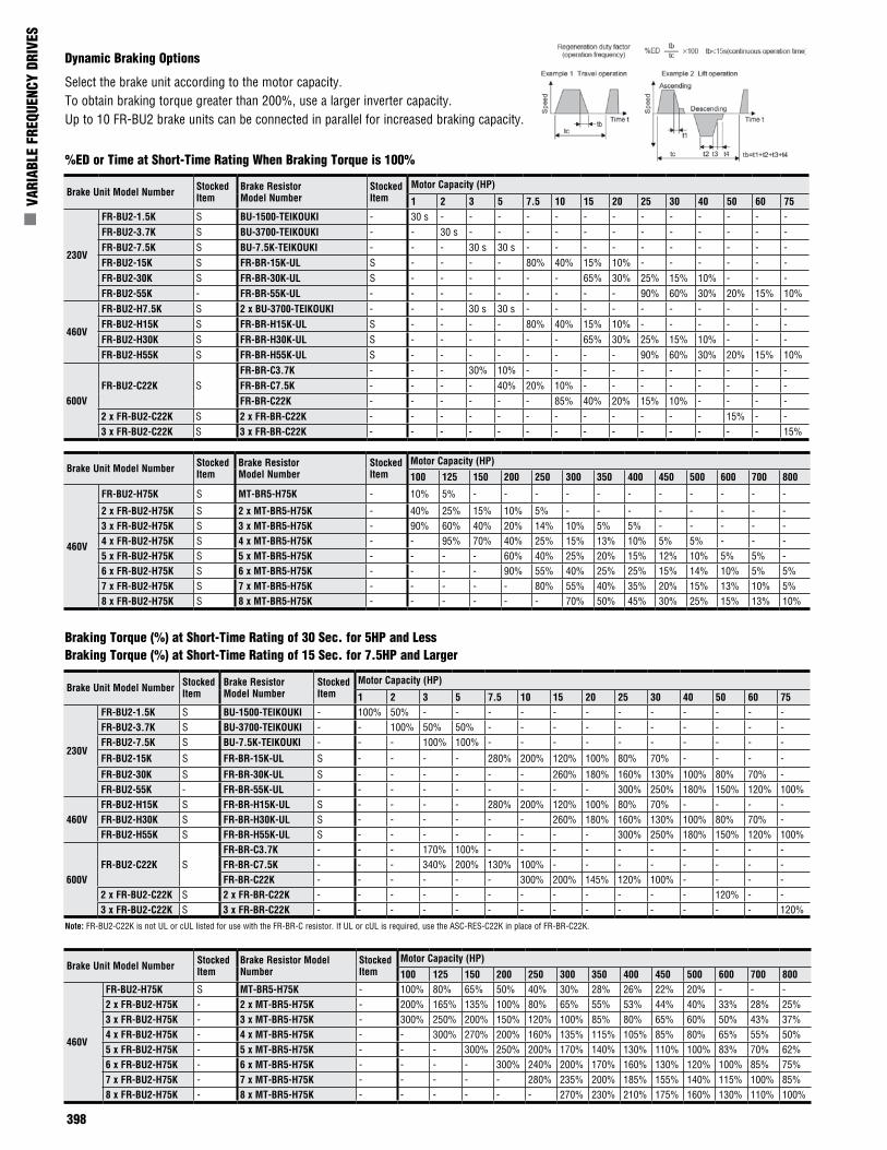
398
n V
ARIA
BLE
FREQ
UENC
Y DR
IVES
Dynamic Braking Options
%ED or Time at Short-Time Rating When Braking Torque is 100%
Select the brake unit according to the motor capacity.To obtain braking torque greater than 200%, use a larger inverter capacity.Up to 10 FR-BU2 brake units can be connected in parallel for increased braking capacity.
Brake Unit Model Number Stocked Item
Brake Resistor Model Number
Stocked Item
Motor Capacity (HP)
1 2 3 5 7.5 10 15 20 25 30 40 50 60 75
230V
FR-BU2-1.5K S BU-1500-TEIKOUKI - 30 s - - - - - - - - - - - - -FR-BU2-3.7K S BU-3700-TEIKOUKI - - 30 s - - - - - - - - - - - -FR-BU2-7.5K S BU-7.5K-TEIKOUKI - - - 30 s 30 s - - - - - - - - - -FR-BU2-15K S FR-BR-15K-UL S - - - - 80% 40% 15% 10% - - - - - -FR-BU2-30K S FR-BR-30K-UL S - - - - - - 65% 30% 25% 15% 10% - - -FR-BU2-55K - FR-BR-55K-UL - - - - - - - - - 90% 60% 30% 20% 15% 10%
460V
FR-BU2-H7.5K S 2 x BU-3700-TEIKOUKI - - - 30 s 30 s - - - - - - - - - -FR-BU2-H15K S FR-BR-H15K-UL S - - - - 80% 40% 15% 10% - - - - - -FR-BU2-H30K S FR-BR-H30K-UL S - - - - - - 65% 30% 25% 15% 10% - - -FR-BU2-H55K S FR-BR-H55K-UL S - - - - - - - - 90% 60% 30% 20% 15% 10%
600VFR-BU2-C22K S
FR-BR-C3.7K - - - 30% 10% - - - - - - - - - -FR-BR-C7.5K - - - - 40% 20% 10% - - - - - - - -FR-BR-C22K - - - - - - 85% 40% 20% 15% 10% - - - -
2 x FR-BU2-C22K S 2 x FR-BR-C22K - - - - - - - - - - - - 15% - -3 x FR-BU2-C22K S 3 x FR-BR-C22K - - - - - - - - - - - - - - 15%
Brake Unit Model Number Stocked Item
Brake Resistor Model Number
Stocked Item
Motor Capacity (HP)
100 125 150 200 250 300 350 400 450 500 600 700 800
460V
FR-BU2-H75K S MT-BR5-H75K - 10% 5% - - - - - - - - - - -
2 x FR-BU2-H75K S 2 x MT-BR5-H75K - 40% 25% 15% 10% 5% - - - - - - - -3 x FR-BU2-H75K S 3 x MT-BR5-H75K - 90% 60% 40% 20% 14% 10% 5% 5% - - - - -4 x FR-BU2-H75K S 4 x MT-BR5-H75K - - 95% 70% 40% 25% 15% 13% 10% 5% 5% - - -5 x FR-BU2-H75K S 5 x MT-BR5-H75K - - - - 60% 40% 25% 20% 15% 12% 10% 5% 5% -6 x FR-BU2-H75K S 6 x MT-BR5-H75K - - - - 90% 55% 40% 25% 25% 15% 14% 10% 5% 5%7 x FR-BU2-H75K S 7 x MT-BR5-H75K - - - - - 80% 55% 40% 35% 20% 15% 13% 10% 5%8 x FR-BU2-H75K S 8 x MT-BR5-H75K - - - - - - 70% 50% 45% 30% 25% 15% 13% 10%
Braking Torque (%) at Short-Time Rating of 30 Sec. for 5HP and LessBraking Torque (%) at Short-Time Rating of 15 Sec. for 7.5HP and Larger
Brake Unit Model Number Stocked Item
Brake Resistor Model Number
Stocked Item
Motor Capacity (HP)
1 2 3 5 7.5 10 15 20 25 30 40 50 60 75
230V
FR-BU2-1.5K S BU-1500-TEIKOUKI - 100% 50% - - - - - - - - - - - -FR-BU2-3.7K S BU-3700-TEIKOUKI - - 100% 50% 50% - - - - - - - - - -FR-BU2-7.5K S BU-7.5K-TEIKOUKI - - - 100% 100% - - - - - - - - - -
FR-BU2-15K S FR-BR-15K-UL S - - - - 280% 200% 120% 100% 80% 70% - - - -
FR-BU2-30K S FR-BR-30K-UL S - - - - - - 260% 180% 160% 130% 100% 80% 70% -FR-BU2-55K - FR-BR-55K-UL - - - - - - - - - 300% 250% 180% 150% 120% 100%
460VFR-BU2-H15K S FR-BR-H15K-UL S - - - - 280% 200% 120% 100% 80% 70% - - - -FR-BU2-H30K S FR-BR-H30K-UL S - - - - - - 260% 180% 160% 130% 100% 80% 70% -FR-BU2-H55K S FR-BR-H55K-UL S - - - - - - - - 300% 250% 180% 150% 120% 100%
600VFR-BU2-C22K S
FR-BR-C3.7K - - - 170% 100% - - - - - - - - - -FR-BR-C7.5K - - - 340% 200% 130% 100% - - - - - - - -FR-BR-C22K - - - - - - 300% 200% 145% 120% 100% - - - -
2 x FR-BU2-C22K S 2 x FR-BR-C22K - - - - - - - - - - - - 120% - -3 x FR-BU2-C22K S 3 x FR-BR-C22K - - - - - - - - - - - - - - 120%
Brake Unit Model Number Stocked Item
Brake Resistor Model Number
Stocked Item
Motor Capacity (HP)
100 125 150 200 250 300 350 400 450 500 600 700 800
460V
FR-BU2-H75K S MT-BR5-H75K - 100% 80% 65% 50% 40% 30% 28% 26% 22% 20% - - -2 x FR-BU2-H75K - 2 x MT-BR5-H75K - 200% 165% 135% 100% 80% 65% 55% 53% 44% 40% 33% 28% 25%3 x FR-BU2-H75K - 3 x MT-BR5-H75K - 300% 250% 200% 150% 120% 100% 85% 80% 65% 60% 50% 43% 37%4 x FR-BU2-H75K - 4 x MT-BR5-H75K - - 300% 270% 200% 160% 135% 115% 105% 85% 80% 65% 55% 50%5 x FR-BU2-H75K - 5 x MT-BR5-H75K - - - 300% 250% 200% 170% 140% 130% 110% 100% 83% 70% 62%6 x FR-BU2-H75K - 6 x MT-BR5-H75K - - - - 300% 240% 200% 170% 160% 130% 120% 100% 85% 75%7 x FR-BU2-H75K - 7 x MT-BR5-H75K - - - - - 280% 235% 200% 185% 155% 140% 115% 100% 85%8 x FR-BU2-H75K - 8 x MT-BR5-H75K - - - - - - 270% 230% 210% 175% 160% 130% 110% 100%
Note: FR-BU2-C22K is not UL or cUL listed for use with the FR-BR-C resistor. If UL or cUL is required, use the ASC-RES-C22K in place of FR-BR-C22K.
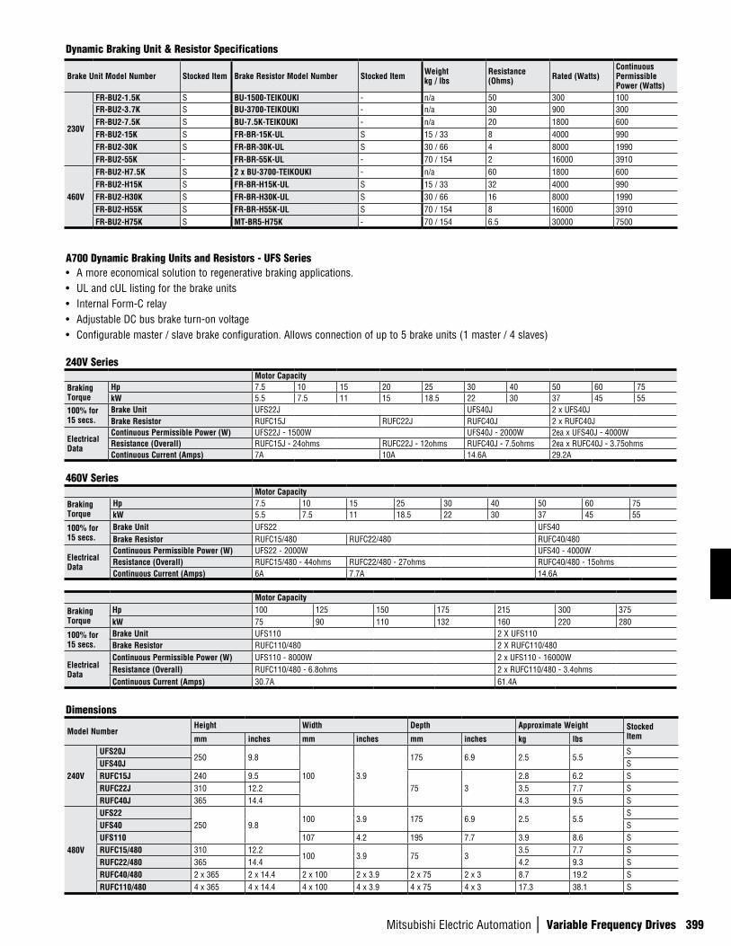
Mitsubishi Electric Automation | Variable Frequency Drives 399
A700 Dynamic Braking Units and Resistors - UFS Series• A more economical solution to regenerative braking applications.• UL and cUL listing for the brake units• Internal Form-C relay• Adjustable DC bus brake turn-on voltage• Configurable master / slave brake configuration. Allows connection of up to 5 brake units (1 master / 4 slaves)
240V SeriesMotor Capacity
Braking Torque
Hp 7.5 10 15 20 25 30 40 50 60 75kW 5.5 7.5 11 15 18.5 22 30 37 45 55
100% for 15 secs.
Brake Unit UFS22J UFS40J 2 x UFS40JBrake Resistor RUFC15J RUFC22J RUFC40J 2 x RUFC40J
Electrical Data
Continuous Permissible Power (W) UFS22J - 1500W UFS40J - 2000W 2ea x UFS40J - 4000WResistance (Overall) RUFC15J - 24ohms RUFC22J - 12ohms RUFC40J - 7.5ohms 2ea x RUFC40J - 3.75ohmsContinuous Current (Amps) 7A 10A 14.6A 29.2A
Dynamic Braking Unit & Resistor Specifications
Brake Unit Model Number Stocked Item Brake Resistor Model Number Stocked Item Weight kg / lbs
Resistance (Ohms) Rated (Watts)
Continuous Permissible Power (Watts)
230V
FR-BU2-1.5K S BU-1500-TEIKOUKI - n/a 50 300 100FR-BU2-3.7K S BU-3700-TEIKOUKI - n/a 30 900 300FR-BU2-7.5K S BU-7.5K-TEIKOUKI - n/a 20 1800 600FR-BU2-15K S FR-BR-15K-UL S 15 / 33 8 4000 990FR-BU2-30K S FR-BR-30K-UL S 30 / 66 4 8000 1990FR-BU2-55K - FR-BR-55K-UL - 70 / 154 2 16000 3910
460V
FR-BU2-H7.5K S 2 x BU-3700-TEIKOUKI - n/a 60 1800 600FR-BU2-H15K S FR-BR-H15K-UL S 15 / 33 32 4000 990FR-BU2-H30K S FR-BR-H30K-UL S 30 / 66 16 8000 1990FR-BU2-H55K S FR-BR-H55K-UL S 70 / 154 8 16000 3910FR-BU2-H75K S MT-BR5-H75K - 70 / 154 6.5 30000 7500
460V SeriesMotor Capacity
Braking Torque
Hp 7.5 10 15 25 30 40 50 60 75kW 5.5 7.5 11 18.5 22 30 37 45 55
100% for 15 secs.
Brake Unit UFS22 UFS40Brake Resistor RUFC15/480 RUFC22/480 RUFC40/480
Electrical Data
Continuous Permissible Power (W) UFS22 - 2000W UFS40 - 4000WResistance (Overall) RUFC15/480 - 44ohms RUFC22/480 - 27ohms RUFC40/480 - 15ohmsContinuous Current (Amps) 6A 7.7A 14.6A
Motor Capacity
Braking Torque
Hp 100 125 150 175 215 300 375kW 75 90 110 132 160 220 280
100% for 15 secs.
Brake Unit UFS110 2 X UFS110Brake Resistor RUFC110/480 2 X RUFC110/480
Electrical Data
Continuous Permissible Power (W) UFS110 - 8000W 2 x UFS110 - 16000WResistance (Overall) RUFC110/480 - 6.8ohms 2 x RUFC110/480 - 3.4ohmsContinuous Current (Amps) 30.7A 61.4A
Dimensions
Model NumberHeight Width Depth Approximate Weight Stocked
Itemmm inches mm inches mm inches kg lbs
240V
UFS20J250 9.8
100 3.9
175 6.9 2.5 5.5S
UFS40J SRUFC15J 240 9.5
75 32.8 6.2 S
RUFC22J 310 12.2 3.5 7.7 SRUFC40J 365 14.4 4.3 9.5 S
480V
UFS22250 9.8
100 3.9 175 6.9 2.5 5.5S
UFS40 SUFS110 107 4.2 195 7.7 3.9 8.6 SRUFC15/480 310 12.2
100 3.9 75 33.5 7.7 S
RUFC22/480 365 14.4 4.2 9.3 SRUFC40/480 2 x 365 2 x 14.4 2 x 100 2 x 3.9 2 x 75 2 x 3 8.7 19.2 SRUFC110/480 4 x 365 4 x 14.4 4 x 100 4 x 3.9 4 x 75 4 x 3 17.3 38.1 S
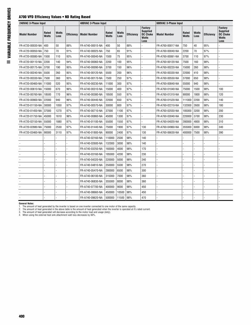
400
n V
ARIA
BLE
FREQ
UENC
Y DR
IVES
A700 VFD Efficiency Values • ND Rating Based
General Notes:1. The amount of heat generated by the inverter is based on one inverter connected to one motor of the same capacity.2. The amount of heat generated in the above table is the amount of heat generated when the inverter is operated at it’s rated current.3. The amount of heat generated will decrease according to the motor load and usage (duty).4. When using the external heat sink attachment watt loss decreases by 60%.
240VAC 3-Phase Input 480VAC 3-Phase Input 600VAC 3-Phase Input
Model Number Rated Watts
Watts Loss Efficiency Model Number Rated
WattsWatts Loss Efficiency
Factory Supplied DC Choke Watts Loss
Model Number Rated Watts
Watts Loss Efficiency
Factory Supplied DC Choke Watts Loss
FR-A720-00030-NA 400 50 88% FR-A740-00015-NA 400 50 88% - FR-A760-00017-NA 750 40 95% -
FR-A720-00050-NA 750 70 91% FR-A740-00025-NA 750 65 91% - FR-A760-00040-NA 2200 70 97% -
FR-A720-00080-NA 1500 110 93% FR-A740-00040-NA 1500 75 95% - FR-A760-00061-NA 3700 110 97% -
FR-A720-00110-NA 2200 140 94% FR-A740-00060-NA 2200 100 95% - FR-A760-00120-NA 7500 160 98% -
FR-A720-00175-NA 3700 190 95% FR-A740-00090-NA 3700 150 96% - FR-A760-00220-NA 15000 260 98% -
FR-A720-00240-NA 5500 260 95% FR-A740-00120-NA 5500 200 96% - FR-A760-00330-NA 22000 410 98% -
FR-A720-00330-NA 7500 360 95% FR-A740-00170-NA 7500 250 97% - FR-A760-00550-NA 37000 650 98% -
FR-A720-00460-NA 11000 520 95% FR-A740-00230-NA 11000 300 97% - FR-A760-00840-NA 55000 940 98% -
FR-A720-00610-NA 15000 670 96% FR-A740-00310-NA 15000 400 97% - FR-A760-01040-NA 75000 1500 98% 100
FR-A720-00760-NA 18500 770 96% FR-A740-00380-NA 18500 550 97% - FR-A760-01310-NA 90000 1800 98% 120
FR-A720-00900-NA 22000 940 96% FR-A740-00440-NA 22000 650 97% - FR-A760-01520-NA 111000 2200 98% 140
FR-A720-01150-NA 30000 1050 97% FR-A740-00570-NA 30000 800 97% - FR-A760-02210-NA 132000 2600 98% 180
FR-A720-01450-NA 37000 1270 97% FR-A740-00710-NA 37000 1100 97% - FR-A760-02550-NA 185000 3200 98% 200
FR-A720-01750-NA 45000 1610 96% FR-A740-00860-NA 45000 1300 97% - FR-A760-03040-NA 220000 3700 98% 230
FR-A720-02150-NA 55000 1880 97% FR-A740-01100-NA 55000 1550 97% - FR-A760-04020-NA 280000 4800 98% 310
FR-A720-02880-NA 75000 2530 97% FR-A740-01440-NA 75000 1900 97% 130 FR-A760-04960-NA 355000 6000 98% 340
FR-A720-03460-NA 90000 3110 97% FR-A740-01800-NA 90000 2400 97% 130 FR-A760-06630-NA 400000 7500 98% 390
- - - - FR-A740-02160-NA 110000 2500 98% 140 - - - - -
- - - - FR-A740-02600-NA 132000 3000 98% 140 - - - - -
- - - - FR-A740-03250-NA 160000 4000 98% 170 - - - - -
- - - - FR-A740-03160-NA 185000 4200 98% 230 - - - - -
- - - - FR-A740-04320-NA 220000 5000 98% 240 - - - - -
- - - - FR-A740-04810-NA 250000 5500 98% 270 - - - - -
- - - - FR-A740-05470-NA 280000 6500 98% 300 - - - - -
- - - - FR-A740-06100-NA 315000 7000 98% 360 - - - - -
- - - - FR-A740-06830-NA 355000 8000 98% 360 - - - - -
- - - - FR-A740-07700-NA 400000 9000 98% 450 - - - - -
- - - - FR-A740-08660-NA 450000 10500 98% 450 - - - - -
- - - - FR-A740-09620-NA 500000 11500 98% 470 - - - - -
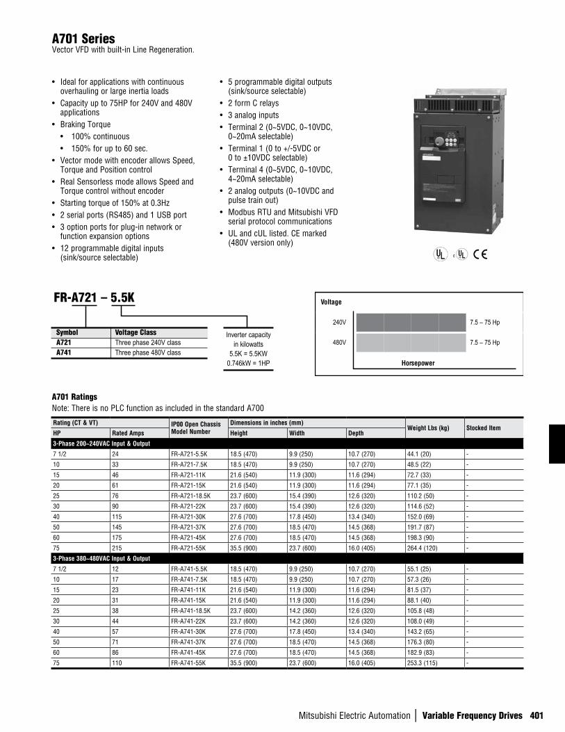
Mitsubishi Electric Automation | Variable Frequency Drives 401
A701 SeriesVector VFD with built-in Line Regeneration.
• Ideal for applications with continuous overhauling or large inertia loads
• Capacity up to 75HP for 240V and 480V applications
• Braking Torque• 100% continuous• 150% for up to 60 sec.
• Vector mode with encoder allows Speed, Torque and Position control
• Real Sensorless mode allows Speed and Torque control without encoder
• Starting torque of 150% at 0.3Hz• 2 serial ports (RS485) and 1 USB port• 3 option ports for plug-in network or
function expansion options• 12 programmable digital inputs
(sink/source selectable)
• 5 programmable digital outputs (sink/source selectable)
• 2 form C relays• 3 analog inputs • Terminal 2 (0~5VDC, 0~10VDC,
0~20mA selectable)• Terminal 1 (0 to +/-5VDC or
0 to ±10VDC selectable)• Terminal 4 (0~5VDC, 0~10VDC,
4~20mA selectable)• 2 analog outputs (0~10VDC and
pulse train out)• Modbus RTU and Mitsubishi VFD
serial protocol communications• UL and cUL listed. CE marked
(480V version only)
A701 RatingsNote: There is no PLC function as included in the standard A700
Rating (CT & VT) IP00 Open Chassis Model Number
Dimensions in inches (mm)Weight Lbs (kg) Stocked Item
HP Rated Amps Height Width Depth
3-Phase 200~240VAC Input & Output
7 1/2 24 FR-A721-5.5K 18.5 (470) 9.9 (250) 10.7 (270) 44.1 (20) -
10 33 FR-A721-7.5K 18.5 (470) 9.9 (250) 10.7 (270) 48.5 (22) -
15 46 FR-A721-11K 21.6 (540) 11.9 (300) 11.6 (294) 72.7 (33) -
20 61 FR-A721-15K 21.6 (540) 11.9 (300) 11.6 (294) 77.1 (35) -
25 76 FR-A721-18.5K 23.7 (600) 15.4 (390) 12.6 (320) 110.2 (50) -
30 90 FR-A721-22K 23.7 (600) 15.4 (390) 12.6 (320) 114.6 (52) -
40 115 FR-A721-30K 27.6 (700) 17.8 (450) 13.4 (340) 152.0 (69) -
50 145 FR-A721-37K 27.6 (700) 18.5 (470) 14.5 (368) 191.7 (87) -
60 175 FR-A721-45K 27.6 (700) 18.5 (470) 14.5 (368) 198.3 (90) -
75 215 FR-A721-55K 35.5 (900) 23.7 (600) 16.0 (405) 264.4 (120) -
3-Phase 380~480VAC Input & Output
7 1/2 12 FR-A741-5.5K 18.5 (470) 9.9 (250) 10.7 (270) 55.1 (25) -
10 17 FR-A741-7.5K 18.5 (470) 9.9 (250) 10.7 (270) 57.3 (26) -
15 23 FR-A741-11K 21.6 (540) 11.9 (300) 11.6 (294) 81.5 (37) -
20 31 FR-A741-15K 21.6 (540) 11.9 (300) 11.6 (294) 88.1 (40) -
25 38 FR-A741-18.5K 23.7 (600) 14.2 (360) 12.6 (320) 105.8 (48) -
30 44 FR-A741-22K 23.7 (600) 14.2 (360) 12.6 (320) 108.0 (49) -
40 57 FR-A741-30K 27.6 (700) 17.8 (450) 13.4 (340) 143.2 (65) -
50 71 FR-A741-37K 27.6 (700) 18.5 (470) 14.5 (368) 176.3 (80) -
60 86 FR-A741-45K 27.6 (700) 18.5 (470) 14.5 (368) 182.9 (83) -
75 110 FR-A741-55K 35.5 (900) 23.7 (600) 16.0 (405) 253.3 (115) -
Symbol Voltage ClassA721 Three phase 240V classA741 Three phase 480V class
FR-A721 – 5.5K
Inverter capacityin kilowatts
5.5K = 5.5KW0.746kW = 1HP
Voltage
240V 7.5 – 75 Hp
480V 7.5 – 75 Hp
Horsepower
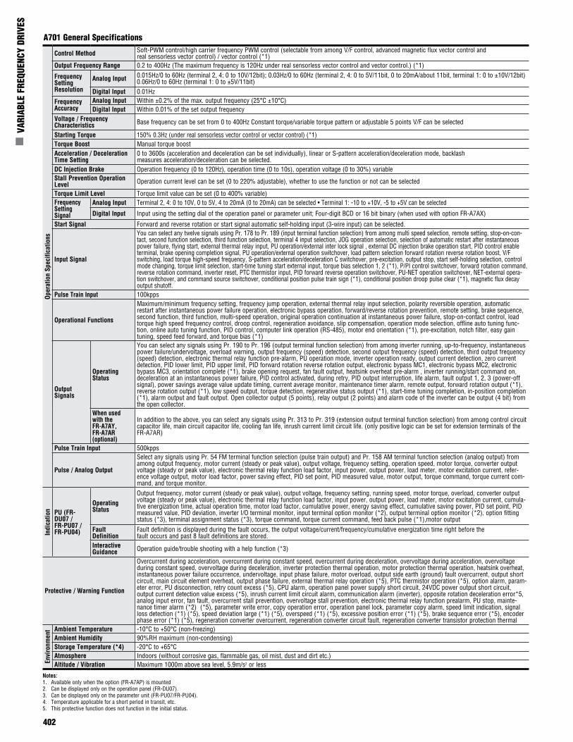
402
n V
ARIA
BLE
FREQ
UENC
Y DR
IVES
A701 General Specifications
Notes:1. Available only when the option (FR-A7AP) is mounted2. Can be displayed only on the operation panel (FR-DU07).3. Can be displayed only on the parameter unit (FR-PU07/FR-PU04).4. Temperature applicable for a short period in transit, etc.5. This protective function does not function in the initial status.
Oper
atio
n Sp
ecifi
catio
nsControl Method Soft-PWM control/high carrier frequency PWM control (selectable from among V/F control, advanced magnetic flux vector control and
real sensorless vector control) / vector control (*1)Output Frequency Range 0.2 to 400Hz (The maximum frequency is 120Hz under real sensorless vector control and vector control.) (*1)
Frequency Setting Resolution
Analog Input 0.015Hz/0 to 60Hz (terminal 2, 4: 0 to 10V/12bit); 0.03Hz/0 to 60Hz (terminal 2, 4: 0 to 5V/11bit, 0 to 20mA/about 11bit, terminal 1: 0 to ±10V/12bit)0.06Hz/0 to 60Hz (terminal 1: 0 to ±5V/11bit)
Digital Input 0.01Hz Frequency Accuracy
Analog Input Within ±0.2% of the max. output frequency (25°C ±10°C) Digital Input Within 0.01% of the set output frequency
Voltage / Frequency Characteristics Base frequency can be set from 0 to 400Hz Constant torque/variable torque pattern or adjustable 5 points V/F can be selected
Starting Torque 150% 0.3Hz (under real sensorless vector control or vector control) (*1)Torque Boost Manual torque boost Acceleration / Deceleration Time Setting
0 to 3600s (acceleration and deceleration can be set individually), linear or S-pattern acceleration/deceleration mode, backlashmeasures acceleration/deceleration can be selected.
DC Injection Brake Operation frequency (0 to 120Hz), operation time (0 to 10s), operation voltage (0 to 30%) variableStall Prevention Operation Level Operation current level can be set (0 to 220% adjustable), whether to use the function or not can be selected
Torque Limit Level Torque limit value can be set (0 to 400% variable)Frequency Setting Signal
Analog Input Terminal 2, 4: 0 to 10V, 0 to 5V, 4 to 20mA (0 to 20mA) can be selected • Terminal 1: -10 to +10V, -5 to +5V can be selected
Digital Input Input using the setting dial of the operation panel or parameter unit; Four-digit BCD or 16 bit binary (when used with option FR-A7AX)
Start Signal Forward and reverse rotation or start signal automatic self-holding input (3-wire input) can be selected.
Input Signal
You can select any twelve signals using Pr. 178 to Pr. 189 (input terminal function selection) from among multi speed selection, remote setting, stop-on-con-tact, second function selection, third function selection, terminal 4 input selection, JOG operation selection, selection of automatic restart after instantaneous power failure, flying start, external thermal relay input, PU operation/external inter lock signal , external DC injection brake operation start, PID control enable terminal, brake opening completion signal, PU operation/external operation switchover, load pattern selection forward rotation reverse rotation boost, V/F switching, load torque high-speed frequency, S-pattern acceleration/deceleration C switchover, pre-excitation, output stop, start self-holding selection, control mode changing, torque limit selection, start-time tuning start external input, torque bias selection 1, 2 (*1), P/PI control switchover, forward rotation command, reverse rotation command, inverter reset, PTC thermistor input, PID forward reverse operation switchover, PU-NET operation switchover, NET-external opera-tion switchover, and command source switchover, conditional position pulse train sign (*1), conditional position droop pulse clear (*1), magnetic flux decay output shutoff.
Pulse Train Input 100kpps
Operational Functions
Maximum/minimum frequency setting, frequency jump operation, external thermal relay input selection, polarity reversible operation, automatic restart after instantaneous power failure operation, electronic bypass operation, forward/reverse rotation prevention, remote setting, brake sequence, second function, third function, multi-speed operation, original operation continuation at instantaneous power failure, stop-on-contact control, load torque high speed frequency control, droop control, regeneration avoidance, slip compensation, operation mode selection, offline auto tuning func-tion, online auto tuning function, PID control, computer link operation (RS-485), motor end orientation (*1), pre-excitation, notch filter, easy gain tuning, speed feed forward, and torque bias (*1)
Output Signals
Operating Status
You can select any signals using Pr. 190 to Pr. 196 (output terminal function selection) from among inverter running, up-to-frequency, instantaneous power failure/undervoltage, overload warning, output frequency (speed) detection, second output frequency (speed) detection, third output frequency (speed) detection, electronic thermal relay function pre-alarm, PU operation mode, inverter operation ready, output current detection, zero current detection, PID lower limit, PID upper limit, PID forward rotation reverse rotation output, electronic bypass MC1, electronic bypass MC2, electronic bypass MC3, orientation complete (*1), brake opening request, fan fault output, heatsink overheat pre-alarm , inverter running/start command on, deceleration at an instantaneous power failure, PID control activated, during retry, PID output interruption, life alarm, fault output 1, 2, 3 (power-off signal), power savings average value update timing, current average monitor, maintenance timer alarm, remote output, forward rotation output (*1), reverse rotation output (*1), low speed output, torque detection, regenerative status output (*1), start-time tuning completion, in-position completion (*1), alarm output and fault output. Open collector output (5 points), relay output (2 points) and alarm code of the inverter can be output (4 bit) from the open collector.
When used with the FR-A7AY, FR-A7AR (optional)
In addition to the above, you can select any signals using Pr. 313 to Pr. 319 (extension output terminal function selection) from among control circuit capacitor life, main circuit capacitor life, cooling fan life, inrush current limit circuit life. (only positive logic can be set for extension terminals of the FR-A7AR)
Pulse Train Input 500kpps
Pulse / Analog Output
Select any signals using Pr. 54 FM terminal function selection (pulse train output) and Pr. 158 AM terminal function selection (analog output) from among output frequency, motor current (steady or peak value), output voltage, frequency setting, operation speed, motor torque, converter output voltage (steady or peak value), electronic thermal relay function load factor, input power, output power, load meter, motor excitation current, refer-ence voltage output, motor load factor, power saving effect, PID set point, PID measured value, motor output, torque command, torque current com-mand, and torque monitor.
Indi
catio
n PU (FR-DU07 / FR-PU07 / FR-PU04)
Operating Status
Output frequency, motor current (steady or peak value), output voltage, frequency setting, running speed, motor torque, overload, converter output voltage (steady or peak value), electronic thermal relay function load factor, input power, output power, load meter, motor excitation current, cumula-tive energization time, actual operation time, motor load factor, cumulative power, energy saving effect, cumulative saving power, PID set point, PID measured value, PID deviation, inverter I/O terminal monitor, input terminal option monitor (*2), output terminal option monitor (*2), option fitting status (*3), terminal assignment status (*3), torque command, torque current command, feed back pulse (*1),motor output
Fault Definition
Fault definition is displayed during the fault occurs, the output voltage/current/frequency/cumulative energization time right before thefault occurs and past 8 fault definitions are stored.
Interactive Guidance Operation guide/trouble shooting with a help function (*3)
Protective / Warning Function
Overcurrent during acceleration, overcurrent during constant speed, overcurrent during deceleration, overvoltage during acceleration, overvoltage during constant speed, overvoltage during deceleration, inverter protection thermal operation, motor protection thermal operation, heatsink overheat, instantaneous power failure occurrence, undervoltage, input phase failure, motor overload, output side earth (ground) fault overcurrent, output short circuit, main circuit element overheat, output phase failure, external thermal relay operation (*5), PTC thermistor operation (*5), option alarm, param-eter error, PU disconnection, retry count excess (*5), CPU alarm, operation panel power supply short circuit, 24VDC power output short circuit, output current detection value excess (*5), inrush current limit circuit alarm, communication alarm (inverter), opposite rotation deceleration error*5, analog input error, fan fault, overcurrent stall prevention, overvoltage stall prevention, electronic thermal relay function prealarm, PU stop, mainte-nance timer alarm (*2) (*5), parameter write error, copy operation error, operation panel lock, parameter copy alarm, speed limit indication, signal loss detection (*1) (*5), speed deviation large (*1) (*5), overspeed (*1) (*5), excessive position error (*1) (*5), brake sequence error (*5), encoder phase error (*1) (*5), regeneration converter overcurrent, regeneration converter circuit fault, regeneration converter transistor protection thermal
Envi
ronm
ent Ambient Temperature -10°C to +50°C (non-freezing)
Ambient Humidity 90%RH maximum (non-condensing)Storage Temperature (*4) -20°C to +65°CAtmosphere Indoors (without corrosive gas, flammable gas, oil mist, dust and dirt etc.)Altitude / Vibration Maximum 1000m above sea level, 5.9m/s2 or less
Mitsubishi Electric Automation | Variable Frequency Drives 403
R/L1S/L2T/L3
R1/L11S1/L21
PC
10E(+10V)
10(+5V)
2
(Analog common)
23
1
1
4
C1
B1
A1
UVW
0 to ±10VDC
0 to 5VDC0 to 10VDC
MC
Main circuit
Control circuit
C2
B2
A2
IM
0 to 20mADC
AU
PTC
TXD+
TXD-
RXD+
RXD-
SGGND
SIN
K
SO
UR
CE
*3
*2
*4
STF
STR
STOP
RH
RM
RL
JOG
RT
MRS
RES
AU
CS
SD
RUN
SU
IPF
OL
FU
SE
(+)(-)
5
VCC
(+)(-)
5V
*1 Earth (Ground)
N/-P/+
*2. JOG terminal can be usedas pulse train input terminal.Use Pr. 291 to selectJOG/pulse.
Main circuit terminal
Control circuit terminal
Three-phase AC power supply
MCCB
Jumper
Earth(Ground)
selected
selected0 to ±5VDC *4
4 to 20mADC0 to 5VDC0 to 10VDC
selected *4
Option connector 1
Option connector 2
Option connector 3
Connectorfor plug-in option connection
Frequency setting signal (Analog)
Frequency setting potentiometer
1/2W1kΩ*5
Control input signals (No voltage input allowed)Forwardrotation
startReverserotation
start
Start self-holding selection
Terminal functions vary with the input terminal assignment (Pr. 178 to Pr. 189)
Middlespeed
High speed
Low speed
Multi-speedselection
Jog mode
Second function selection
Output stop
Reset
Terminal 4 input selection(Current input selection)
Selection of automatic restart after instantaneous
power failure
USBconnector
PUconnector
Terminating resistor
Data reception
Data transmission
RS-485 terminals
Open collector output commonSink/source common
Frequency detection
Running
Up to frequency
Instantaneouspower failure
Overload
Terminal functions vary with the output terminal assignment (Pr. 190 to Pr. 194)
Open collector output
(Permissible load current 100mA)
Relay output 2
Relay output 1(Fault output)
Terminal functions vary with the output terminal assignment (Pr. 195, Pr. 196)
Relay output
Motor
*3. AU terminal can be used as PTC input terminal.
*1. To supply power to the control circuit separately, remove the jumper across R1/L11 and S1/L21.
*7. It is not necessary when calibrating the indicator from the operation panel.
*9. Because the FR Configurator has not worked with the FR-A701 series, a USB connector can not be used.
*5. It is recommended to use 2W1kΩwhen the frequency setting signal is changed frequently.
(Initial value)
(Initial value)
(Initial value)
ON4 2
OFF
Voltage/currentinput switch
*4
Auxiliaryinput
Terminal4 input
(Currentinput)
*4. Terminal input specifications can be changed by analog input specifications switchover (Pr. 73, Pr. 267).Set the voltage/current input switch in the OFF position to select voltage input (0 to 5V/0 to10V) and ON to select current input (4 to 20mA).
*9
Sink logic
*6. Do not connect any options to P/+ and N/-.
FM
SD
+ -
AM
5
*8
*8. FM terminal can be used for pulse train output of open collector output using Pr.291.
(+)
(-)(0 to 10VDC)Analog signal output
Moving-coil type1mA full-scale
(Frequency meter, etc.)Indicator
Calibrationresistor *7
24VDC power supply(Common for external power supply transistor)
Contact input common
*6 *6
24V
Inrush current limit circuit
A701 Terminal Connection Diagram
A701 Control Terminal LayoutA1 B1 C1 A2 B2 C2 10E 10 2 5 4
1AMSDRESMRSSTOPAURTRHRMRL
PCCSJOGSTRSTFSDSDFUOLIPFSURUNSE
FM
404
n V
ARIA
BLE
FREQ
UENC
Y DR
IVES
A701 Options
Manuals available for download at www.meau.com
Description Model Number
FR-A701 Applied Manual - Contains wiring details, VFD layout drawings, alarm definitions and complete parameter list with definitions and setting examples
IB(NA)0600337
FR-A701 Basic Manual - Contains wiring details, VFD layout drawings, alarm definitions and parameter list IB(NA)0600331
FR-PU07 - Contains complete instruction sets and screen definitions IB(NA)0600240
Function/Options
Software
Model Number Description Stocked Item
FR-CONFIGURATOR Programming and diagnostic software (ver. 3.20 or greater) S
Instruction Manuals
A701 series supports only the above listed plug-in options.Those options not listed cannot be used with the A701 series.
Parameter Units / Parameter Copy UnitsParameter units are used for operator control, reading and writing parameters, and drive monitoring. Parameter Copy Units also read the drive parameter settings and copy them into non-volatile memory, and can write them into other drives.
Model No. Stocked Item
Func
tion
120VAC Control Input FR-A7AC S
Analog I/O FR-A7AN S
Encoder Feedback FR-A7AP S
Encoder Pulse Dividing Output FR-A7AL S
Relay Output FR-A7AR S
12 Bit Digital Input FR-A7AX S
Digital Output FR-A7AY S
Ext. Analog Output
BiPolar Analog Input
FR-A7AZ -High Res Analog Input
Motor Thermistor
Com
mun
icat
ion
CC-Link FR-A7NC S
ControlNET (*1) FR-A7NCN S
DeviceNet FR-A7ND S
EtherNet/IP (*1) FR-A7NE S
LonWorks FR-A7NL S
Profibus DP FR-A7NP S
SSCNET III FR-A7NS S
Model Number Description Stocked Item
FR-CB201 Extension cable straight plugs on both ends - 1 meter SFR-CB203 Extension cable straight plugs on both ends - 3 meters SFR-CB205 Extension cable straight plugs on both ends - 5 meters SFR-DU07 Control Panel for F700 S
FR-PU07
LCD Multi-lingual Parameter Copy Unit (English, French, Spanish, German, Italian, Swedish, Finnish, Japanese) for operator control, parameter read/write and moni-toring. Stores settings in non-volatile memory. Built-in parameter copy capability. (F/A700 based)
S
FR-ADP FR-DU07 panel mounting adapter S
FR-PU04LCD Multi-lingual Parameter Copy Unit (English, French, Spanish, German, Italian, Swedish, Finnish, Japanese) for operator control, parameter read/write and monitoring.
S
SC-FRPC Serial Communication Cable SFR-PU07BB-L Battery Powered PU07 SFR-RJ45-HUB4 Serial Network Hub - 2 Stations -FR-RJ45-HUB10 Serial Network Hub - 8 Stations -FR-RJ45-TR Terminating Resistor for FR-RJ45-HUB -
Building Management Options
Notes:1. For additional information, visit www.iccdesigns.com2. Physically mounts within VFD and powered by VFD3. Deep control cover is required4. FR-E7TR option recommended. (PU connector not available for use)5. Communication to multiple VFD’s is possible6. Mounted and powered external to VFD
Network Type / Model FR-A7N-ETH (*2,*3,*4)
FR-A7N-XLT (*2,*3,*4)
ETH-1000(*5,*6)
XLTR-1000(*5,*6)
Gate
way
Co
mm
unic
atio
n
BACnet/IP X - X -EtherNet/IP X - X -Modbus TCP X - X -PROFINET IO X - X -BACnet MS/TP - X X XMetasys N2 - X X XSiemens FLN - X - -
Stocked Item S S - -
Mitsubishi Electric Automation | Variable Frequency Drives 405
V500 SeriesVariable Frequency Drives True, Closed Loop Vector Control
This series achieves high precision and fast response that exceeds the performance of conventional general-purpose inverters. They can be used in specialized applications such as line control and elevators.
By incorporating our original all-digital vector control, high starting torque and high speed response have been made possible for both velocity and torque control modes.
• 2 to 75 Horsepower at 240V• 2 to 75 Horsepower at 480V• 100% continuous torque at Zero speed• Auto Tuning to other manufacturer’s constant torque
motor with encoder• Easy to use Parameter Unit
• 4-Quadrant torque control standard• Multiple parameters for tailoring to a wide variety
of applications• Simple positioning included as standard• DC Link Reactor standard (V500L)• Peripheral devices such as power regenerative
converter (FR-CV, FR-RC, MT-RC) available• Communications options: DeviceNet, Profibus DP,
CC-Link, Modbus Plus, SSCNet
Constant TorqueModel Number Stocked Item
Hp Output Amps
3-Phase 240VAC Input / Output
2 9.0 FR-V520-1.5K-NA S
3 13.0 FR-V520-2.2K-NA S
5 20.0 FR-V520-3.7K-NA S
7.5 28.5 FR-V520-5.5K-NA -
10 37.5 FR-V520-7.5K-NA -
15 54 FR-V520-11K-NA -
20 72.8 FR-V520-15K-NA -
25 88 FR-V520-18.5K-NA -
30 103.5 FR-V520-22K-NA S
40 126.5 FR-V520-30K-NA -
50 166.8 FR-V520-37K-NA -
60 198.0 FR-V520-45K-NA -
75 264.0 FR-V520-55K-NA -
Constant TorqueModel Number Stocked Item
Hp Output Amps
3-Phase 480VAC Input / Output
2 4.5 FR-V540-1.5K-NA S
3 6.5 FR-V540-2.2K-NA S
5 10.0 FR-V540-3.7K-NA S
7.5 14.5 FR-V540-5.5K-NA -
10 18.5 FR-V540-7.5K-NA -
15 27.5 FR-V540-11K-NA S
20 35.5 FR-V540-15K-NA S
25 44.0 FR-V540-18.5K-NA -
30 51.8 FR-V540-22K-NA -
40 67.0 FR-V540-30K-NA -
50 86.0 FR-V540-37K-NA S
60 99.0 FR-V540-45K-NA S
75 132.0 FR-V540-55K-NA -
Notes: See next page.
Model FR-V520-_ _K-NA 1.5 2.2 3.7 5.5 7.5 11 15 18.5 22 30 37 45 55
Output
Horsepower Rating (Hp) 2 3 5 7.5 10 15 20 25 30 40 50 60 75
Rated Current (A) 9.0 13.0 20.0 28.5 37.5 54.0 72.8 88.0 103.5 126.5 166.0 198.0 264.0
Overload Current Rating (*1) 150% 60 sec., 200% 0.5 sec. (inverse time characteristics)
Voltage (*2) 3-Phase 200-220V 50 Hz, 200-240V 60 Hz 3-Phase 200-220V 50 Hz, 200-230V 60 Hz
Regenerative Breaking Torque
Max. Time 100%/5 sec. 20% (*5)
Tolerable Work Rate 3% ED (*5) 2% ED (*5) Continuous (*5)
Power Supply
Rated Input, AC Volt. and Frequency 3-Phase 200-220 V 50 Hz, 200-240V 60 Hz 3-Phase 200-220 V 50 Hz, 200-230V 60 Hz
Tolerable AC Voltage Fluctuation 170-242V 50 Hz, 200-264V 60 Hz 170-242V 50 Hz, 170-253V 60 Hz
Tolerable Frequency Fluctuation ±5%
Amount of Instantaneous Voltage Drop that can be Withstood When operated at or above 165 V continuously and voltage falls from rated voltage to under 165 V, 15 ms of continuous operation
Supply (kVA) (*3) 5.0 6.5 10 14 19 23 33 39 48 57 77 90 123
Protective Structure (JEM 1030) Enclosed type (IP20) (*4) Open type (IP00)
Cooling Method Forced air cooling
Approximate Weightkg 3.5 3.5 6 6 6 14 14 21 30 40 40 55 58
lbs 7.7 7.7 13.2 13.2 13.2 30.8 30.8 46.2 66 88 88 121 128
Widthmm 150 150 220 220 250 250 250 250 340 450 450 480 480
inches 5.9 5.9 8.7 8.7 9.9 9.9 9.9 9.9 13.4 17.7 17.7 18.9 18.9
Heightmm 260 260 260 260 400 400 400 400 550 550 550 700 700
inches 10.2 10.2 10.2 10.2 15.8 15.8 15.8 15.8 21.7 21.7 21.7 27.6 27.6
Depthmm 163 163 193 193 218 218 218 218 195 250 250 250 270
inches 6.4 6.4 7.6 7.6 8.6 8.6 8.6 8.6 7.7 9.9 9.9 9.9 10.6
V500 Ratings 240V Class 1.5K - 55K
406
n V
ARIA
BLE
FREQ
UENC
Y DR
IVES
Model Number Length Description Stocked ItemFR-V5NSCBL005 0.5 meter
Connection of Q172CPU to FR-V5NS, FR-V5NS to FR-V5NS
SFR-V5NSCBL01 1 meter SFR-V5NSCBL05 5 meters SFR-V5NSCBL10 10 meters -FR-V5NSCBL20 20 meters -
Dedicated Options V500 Series
Instruction Manuals
Model Model NumberFR-V520 Basic IB(NA)06000064FR-V540 Detailed IB(NA)06000065
FR-V560Basic IB(NA)0600134Detailed IB(NA)0600135
FR-V500LBasic IB-T7311Detailed IB-T7312
SSCNET II Cables
V500 Ratings 480V Class 1.5K - 55KModel FR-V540-_ _K-NA 1.5 2.2 3.7 5.5 7.5 11 15 18.5 22 30 37 45 55
Output
Horsepower Rating (Hp) 2 3 5 7.5 10 15 20 25 30 40 50 60 75Rated Current (A) 4.5 6.5 10.0 14.5 18.5 27.5 35.5 44.0 51.8 67.0 86.0 99.0 132.0Overload Current Rating (*1) 150% 60 sec., 200% 0.5 sec. (inverse time characteristics)Voltage (*2) 3-Phase 380-480V 50 Hz/60 Hz
Regenerative Breaking Torque
Max. Time 100% / 5 sec. 20% (*5)Tolerable Work Rate 2% ED (*5) Continuous (*5)
Power Supply
Rated Input, AC Volt. and Frequency 3-Phase 380-480 V 50 Hz/60 Hz
Tolerable AC Voltage Fluctuation 323-528V 50 Hz/60 HzTolerable Frequency Fluctuation ±5%Amount of Instantaneous Voltage Drop that can be Withstood When operated at or above 320 V continuously and voltage falls from rated voltage to under 320 V, 15 ms of continuous operation
Supply (kVA) (*3) 5.0 6.5 10.2 14 19 23 33 39 48 57 77 90 123Protective Structure (JEM 1030) Enclosed type (IP20) (*4) Open type (IP00)Cooling System Forced air cooling
Approximate Weightkg 3.5 3.5 6 6 14 14 14 14 30 35 35 36 65lbs 7.7 7.7 13.2 13.2 30.8 30.8 30.8 30.8 66 77 77 79 143
Widthmm 150 150 220 220 250 250 250 250 340 450 450 480 480inches 5.9 5.9 8.7 8.7 9.9 9.9 9.9 9.9 13.4 17.7 17.7 18.9 18.9
Heightmm 260 260 260 260 400 400 400 400 550 550 550 700 700inches 10.2 10.2 10.2 10.2 15.8 15.8 15.8 15.8 21.7 21.7 21.7 27.6 27.6
Depthmm 163 163 193 193 218 218 218 218 195 250 250 250 270inches 6.4 6.4 7.6 7.6 8.6 8.6 8.6 8.6 7.7 9.9 9.9 9.9 10.6
Notes:1. The overload current % value indicates the percentage to the inverter’s rated output current. For repeated duty, allow time for the inventer and motor to return to or below the temperature when at
100% load.2. The maximum output voltage cannot exceed the power supply voltage. The maximum output voltage can be set below the power supply voltage.3. The power capacity will vary according to the power supply side impedance (including input reactor and power lines) value.4. When the wiring cover for the network option is removed and built-in options are installed, the protective structure will become open type (IP00).5. For inverter capacities 1.5K to 15K, using the optional high-duty brake resistor (FR-ABR) will provide 100% torque/10% ED.
Model Number Description Installation Manual Stocked Item
FR-PU04V Parameter unit used for operation control, reading and writing parameters, drive monitoring, parameter copy and multi-language IB(NA)0600079 S
FR-V5AP Pulse train input for advanced position control. Differential line receiver: 500kpps, open collector 200kpps IB(NA)0600087 S
FR-V5AX 6 additional multi-function digital inputs and high resolution analog input (16-bit) IB(NA)0600083 -
FR-V5AY 3 additional multi-function digital outputs and encoder pulse ratio output (differential or open collector output) IB(NA)0600085 -
FR-V5AM When used with additional encoder, machine side orientation can be performed IB(NA)0600089 -
FR-V5NS SSCNET motion control network operation IB(NA)0600106E S
FR-V5NE Ethernet option for inverter setup and monitoring using LAN IB(NA)0600108E -
FR-V5AH 3-digit BCD or 12-bit binary code input for high accuracy speed control IB(NA)0600110E -
T-TRC50 Memory option used with setup software (FR-SW1-SETUP-WE) to analyze internal inverter trace data Contact MEAU -
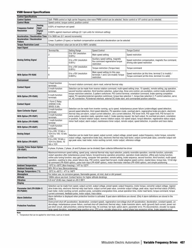
Mitsubishi Electric Automation | Variable Frequency Drives 407
V500 General SpecificationsControl SpecificationsControl System Soft- PWM control or high carrier frequency sine-wave PWM control can be selected. Vector control or V/F control can be selected.Control Mode Speed control, torque control, position control
Frequency Control Resolution
Analog Input 0.03% of maximum set speed
Digital Input 0.003% against maximum settings (0.1 rpm units for minimum setting)
Acceleration / Deceleration Time 0 to 3600 sec (0.1 second increments)Acceleration / Deceleration Pattern Linear, S pattern (3 types) or backlash compensation acceleration/deceleration can be selected
Torque Restriction Level Torque restriction value can be set (0 to 400% variable)Input Signal
Analog Setting Signal
Terminal No. Setting Range Speed Control Torque Control
2 0 to 10V (resolution 0.03%) Main speed setting Speed restriction
1 0 to ±10V (resolution 0.05%)
Auxiliary speed setting, magnetic flux command regenerative torque restriction
Speed restriction compensation, magnetic flux command, driving side speed restriction
3 0 to ±10V (resolution 0.05%) Torque restriction (Torque bias) Torque command
With Option FR-V5AX 6 0 to ±10V (resolution 0.003%)
Main speed setting (in this case, terminals 1 and 2 are invalid) Torque restriction
Speed restriction (at this time, terminal 2 is invalid) / Torque command (at this time, terminal 3 is valid)
Environment
Contact Signal
3 fixed function terminals Forward rotation command, alarm reset, external thermal relay
5 multi-function terminals
Selection can be made from reverse rotation command, multi-speed setting (max. 15 speeds), remote setting, jog operation, second function selection, third function selection, output stop, three-wire control, pre-excitation, control mode switchover, torque restriction selection, S pattern switchover, PID control terminal, orientation command, brake opening completion signal, PU operation/external operation switchover, torque bias selection 1, torque bias selection 2, P control selection, servo on, HC connection, PU/external interlock, external DC brake start, and commanded position selection.
With Option (FR-V5AX) 6 multi-function terminals
Contact Signal1 Form C Relay (230VAC 0.3A, 30VDC 0.3A)
Selection con be made from inverter running, up to speed, instantaneous power failure (undervoltage) speed detection, second speed detection, third speed detection, PU operation mode, overload alarm, regenerative brake pre-alarm, electronic thermal relay pre-alarm, output current detection, zero current detection, PID lower limit, PID upper limit, PID forward /re-verse output, operation ready, operation ready 2. brake opening request, fan fault output, fin overheat pre-alarm, orientation in-position, forward rotation output, reverse rotation output, low speed output, torque detection, regenerative status output, minor fault output, alarm output, maintenance timer output, remote output, speed detection, in-position and trace status
Open Collector Signal 3 multi-function terminals
With Option (FR-V5AY) 3 multi-function terminals
With Option (FR-V5AM) 1 multi-function terminal
With Option (FR-A5AY) 7 multi-function terminals
Analog Output0 to ±10V, 12 bits x 1CH 0 to 10V, 12 bits x 1CH Selection can be made from speed, output current, output voltage, preset speed, output frequency, motor torque, converter
output voltage, regenerative brake duty, electronic thermal relay load factor, output current peak value, converter output volt-age peak value, load meter, motor exciting current, motor output, reference voltage
With Option (FR-A5AY)0 to ±10V, 10 bits x 1CH 0 to 20mA, 10 bits x 1CH
Encoder Pulse Output Option (FR-V5AY) A phase, B phase, Z phase, (A and B phases can be divided) Open collector/differential line driver
Operational Functions
Maximum/minimum speed setting, speed jump, external thermal relay input selection, polarity reversible operation, override function, automatic restart operation after instantaneous power failure, forward/reverse operation prevention, operation mode selection, offline auto tuning function, online auto tuning function, easy gain tuning, computer link operation, remote setting, brake sequence, second function, third function, multi-speed operation, coasting to stop, power failure stop, PID control, speed feed forward, model adaptive speed control, master/slave, torque bias, 12-bit digi-tal command (FR-A5AX option), pulse train input (FR-A5AP option), motor thermistor interface (FR-V5AX option), and simple positioning
Ambient Temperature -10°C to +50°C (Non-freezing) / 14°F to 122°FAmbient Humidity 90% RH or less (Noncondensing)Storage Temperature (*1) -20°C to +65°C / -4°F to 149°FAtmosphere For indoor use; no corrosive gasses, flammable gasses, oil mist, dust or dirt presentAttitude 1000m above sea level. Contact factory for higher altitude deratings.Vibration 5.9 m/s² (0.6G max.) based on JIS C 0911Display
Parameter Unit (FR-DU04-1/FR-PU04V)
Selection can be made from speed, output current, output voltage, preset speed, output frequency, motor torque, converter output voltage, regener-ative brake duty, electronic thermal relay load factor, output current peak value, converter output voltage, peak value, input terminal status (PU04V), load meter, motor exciting current, position pulse, cumulative energization time, actual operation time, motor load factor, torque command, torque current command, feedback pulse, motor output, trace status
Alarm Definition Alarm definition is displayed when protective function is activated. 8 past alarm definitions are stored. (Only 4 alarm definitions are stored in the DU04-1)
Protective Functions
Overcurrent shut-off (acceleration, deceleration, constant speed), regenerative overvoltage shut-off (acceleration, deceleration, constant speed), un-dervoltage, instantaneous power failure, overload shut-off (electronic thermal relay), brake transistor alarm, earth (ground) fault current, power out-put short circuit, stall prevention, external thermal relay, fin overheat, fan fault, option alarm, parameter error, PU disconnection, encoder no-signal, large speed deviation, overspeed large position error, CPU error, encoder phase error, output phase loss excessive retries, brake sequence error
Note:1. Temperature that can be applied for short times, such as in transit.
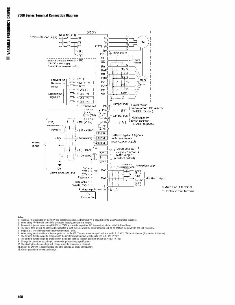
408
n V
ARIA
BLE
FREQ
UENC
Y DR
IVES
Notes:1. Terminal PR is provided on the 15kW and smaller capacities, and terminal PX is provided on the 5.5kW and smaller capacities.2. When using FR-ABR with the 5.5kW or smaller capacity, remove this jumper.3. Remove this jumper when using FR-BEL for 55kW and smaller capacities. DC link reactor included with 75kW and larger.4. The converter’s life will be shortened by repeated in-rush currents when the power is turned ON, so do not turn the power ON and OFF frequently.5. Prepare a ± 10V external power supply for terminals 1 and 3.6. When using a motor without a thermal protector, set Pr.876 “Thermal protector input” to 0 and set Pr.9 (Pr.452) “Electronic thermal (2nd electronic thermal).7. The terminal functions can be changed with the input terminal function selection (Pr.180 to Pr.183, Pr.187)8. The terminal functions can be changed with the output terminal function selection (Pr.190 to Pr.192, Pr.195)9. Change the connector according to the encoder power supply specifications.10. The sink logic and source logic will change when the connector is changed.11. Use of the 2W1kW is recommended when the settings are changed frequently.12. Always ground the inverter and motor.
V500 Series Terminal Connection Diagram
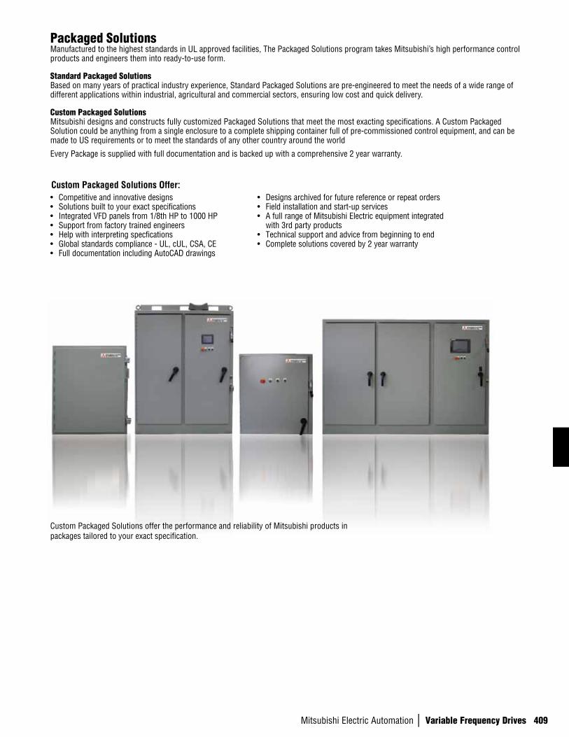
Mitsubishi Electric Automation | Variable Frequency Drives 409
Packaged SolutionsManufactured to the highest standards in UL approved facilities, The Packaged Solutions program takes Mitsubishi’s high performance control products and engineers them into ready-to-use form.
Standard Packaged SolutionsBased on many years of practical industry experience, Standard Packaged Solutions are pre-engineered to meet the needs of a wide range of different applications within industrial, agricultural and commercial sectors, ensuring low cost and quick delivery.
Custom Packaged SolutionsMitsubishi designs and constructs fully customized Packaged Solutions that meet the most exacting specifications. A Custom Packaged Solution could be anything from a single enclosure to a complete shipping container full of pre-commissioned control equipment, and can be made to US requirements or to meet the standards of any other country around the world
Every Package is supplied with full documentation and is backed up with a comprehensive 2 year warranty.
Custom Packaged Solutions offer the performance and reliability of Mitsubishi products in packages tailored to your exact specification.
• Competitive and innovative designs • Solutions built to your exact specifications • Integrated VFD panels from 1/8th HP to 1000 HP• Support from factory trained engineers• Help with interpreting specfications • Global standards compliance - UL, cUL, CSA, CE• Full documentation including AutoCAD drawings
• Designs archived for future reference or repeat orders• Field installation and start-up services • A full range of Mitsubishi Electric equipment integrated
with 3rd party products • Technical support and advice from beginning to end• Complete solutions covered by 2 year warranty
Custom Packaged Solutions Offer:
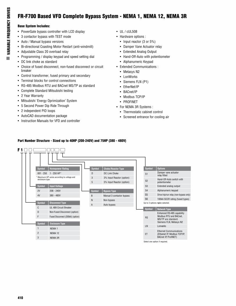
410
n V
ARIA
BLE
FREQ
UENC
Y DR
IVES
• PowerGate bypass controller with LCD display• 3 contactor bypass with TEST mode• Auto / Manual bypass versions• Bi-directional Coasting Motor Restart (anti-windmill)• Adjustable Class 20 overload relay• Programming / display keypad and speed setting dial• DC link choke as standard• Choice of fused disconnect, non-fused disconnect or circuit
breaker• Control transformer, fused primary and secondary• Terminal blocks for control connections• RS-485 Modbus RTU and BACnet MS/TP as standard • Complete Standard Mitsubishi testing• 2 Year Warranty• Mitsubishi ‘Energy Oprimization’ System• 5 Second Power Dip Ride Through• 2 independent PID loops• AutoCAD documentation package• Instruction Manuals for VFD and controller
• UL / cUL508• Hardware options :
• Input reactor (3 or 5%)• Damper Vane Actuator relay• Extended Analog Output• Hand-Off-Auto with potentiometer• Alphanumeric Keypad
• Extended Communications :• Metasys N2• LonWorks• Siemens FLN (P1)• EtherNet/IP• BACnet/IP• Modbus TCP/IP• PROFINET
• For NEMA 3R Systems :• Thermostatic cabinet control• Screened entrance for cooling air
Base System Includes:
FR-F700 Based VFD Complete Bypass System - NEMA 1, NEMA 12, NEMA 3R
Part Number Structure - Sized up to 40HP (208-240V) and 75HP (380 - 480V)
Symbol Horsepower Rating
001 - 250 1 - 250 HP*
Symbol Input Voltage
2V 208 - 240V
4V 380 - 480V
Symbol
D DC Link Choke
3 3% Input Reactor (option)
5 5% Input Reactor (option)
Symbol Bypass Type
B Manual 3 contactor bypass
N Non bypass
A Auto bypassSymbol
C UL 489 Circuit Breaker
D Non-Fused Disconnect (option)
F Fused Disconnect (200kA) (option)
Symbol
1 NEMA 1
2 NEMA 12
3 NEMA 3R
F 1
Symbol
RS
Enhanced RS-485 capabilityModbus RTU and BACnet, MS/TP are standard.Siemens FLN, Metasys N2
LN orLonw ks
ETEthernet Communications(Ethernet IP, Modbus TCP/IP,BACnet IP, ProfiNET)
Select one option if required.
Symbol Options
S1 Damper vane actuator relay fitted
S2 Hand-Off-Auto switch with potentiometer
S3 Extended analog output
S4
S5
S6
Alphanumeric keypad
Drive trip/run relay (non-bypass only)
100kA SCCR rating (fused types)Up to 3 options may be selected.Disconnect Type
Enclosure Type
Choke/Reactor Type
Network Type
* Maximum HP varies according to voltage and enclosure type.
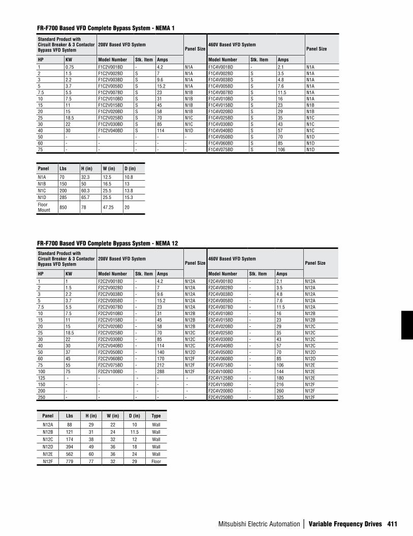
Mitsubishi Electric Automation | Variable Frequency Drives 411
FR-F700 Based VFD Complete Bypass System - NEMA 1
Panel Lbs H (in) W (in) D (in)
N1A 70 32.3 12.5 10.8N1B 150 50 16.5 13N1C 200 60.3 25.5 13.8N1D 285 65.7 25.5 15.3Floor Mount 850 78 47.25 20
Standard Product with Circuit Breaker & 3 Contactor Bypass VFD System
208V Based VFD SystemPanel Size
460V Based VFD SystemPanel Size
HP KW Model Number Stk. Item Amps Model Number Stk. Item Amps
1 0.75 F1C2V001BD - 4.2 N1A F1C4V001BD - 2.1 N1A2 1.5 F1C2V002BD S 7 N1A F1C4V002BD S 3.5 N1A3 2.2 F1C2V003BD S 9.6 N1A F1C4V003BD S 4.8 N1A5 3.7 F1C2V005BD S 15.2 N1A F1C4V005BD S 7.6 N1A7.5 5.5 F1C2V007BD S 23 N1B F1C4V007BD S 11.5 N1A10 7.5 F1C2V010BD S 31 N1B F1C4V010BD S 16 N1A15 11 F1C2V015BD S 45 N1B F1C4V015BD S 23 N1B20 15 F1C2V020BD S 58 N1B F1C4V020BD S 29 N1B25 18.5 F1C2V025BD S 70 N1C F1C4V025BD S 35 N1C30 22 F1C2V030BD S 85 N1C F1C4V030BD S 43 N1C40 30 F1C2V040BD S 114 N1D F1C4V040BD S 57 N1C50 - - - - - F1C4V050BD S 70 N1D60 - - - - - F1C4V060BD S 85 N1D75 - - - - - F1C4V075BD S 106 N1D
FR-F700 Based VFD Complete Bypass System - NEMA 12
Panel Lbs H (in) W (in) D (in) Type
N12A 88 29 22 10 Wall
N12B 121 31 24 11.5 Wall
N12C 174 38 32 12 Wall
N12D 394 49 36 18 Wall
N12E 562 60 36 24 Wall
N12F 779 77 32 29 Floor
Standard Product with Circuit Breaker & 3 Contactor Bypass VFD System
208V Based VFD SystemPanel Size
460V Based VFD SystemPanel Size
HP KW Model Number Stk. Item Amps Model Number Stk. Item Amps
1 1 F2C2V001BD - 4.2 N12A F2C4V001BD - 2.1 N12A2 1.5 F2C2V002BD - 7 N12A F2C4V002BD - 3.5 N12A3 2.2 F2C2V003BD - 9.6 N12A F2C4V003BD - 4.8 N12A5 3.7 F2C2V005BD - 15.2 N12A F2C4V005BD - 7.6 N12A7.5 5.5 F2C2V007BD - 23 N12A F2C4V007BD - 11.5 N12A10 7.5 F2C2V010BD - 31 N12B F2C4V010BD - 16 N12B15 11 F2C2V015BD - 45 N12B F2C4V015BD - 23 N12B20 15 F2C2V020BD - 58 N12B F2C4V020BD - 29 N12C25 18.5 F2C2V025BD - 70 N12C F2C4V025BD - 35 N12C30 22 F2C2V030BD - 85 N12C F2C4V030BD - 43 N12C40 30 F2C2V040BD - 114 N12C F2C4V040BD - 57 N12C50 37 F2C2V050BD - 140 N12D F2C4V050BD - 70 N12D60 45 F2C2V060BD - 170 N12F F2C4V060BD - 85 N12D75 55 F2C2V075BD - 212 N12F F2C4V075BD - 106 N12E100 75 F2C2V100BD - 288 N12F F2C4V100BD - 144 N12E125 - - - - - F2C4V125BD - 180 N12E150 - - - - - F2C4V150BD - 216 N12F200 - - - - - F2C4V200BD - 260 N12F250 - - - - - F2C4V250BD - 325 N12F
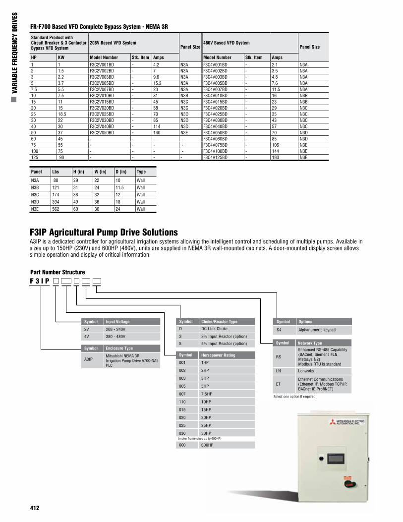
412
n V
ARIA
BLE
FREQ
UENC
Y DR
IVES
FR-F700 Based VFD Complete Bypass System - NEMA 3R
Standard Product with Circuit Breaker & 3 Contactor Bypass VFD System
208V Based VFD SystemPanel Size
460V Based VFD SystemPanel Size
HP KW Model Number Stk. Item Amps Model Number Stk. Item Amps
1 1 F3C2V001BD - 4.2 N3A F3C4V001BD - 2.1 N3A2 1.5 F3C2V002BD - 7 N3A F3C4V002BD - 3.5 N3A3 2.2 F3C2V003BD - 9.6 N3A F3C4V003BD - 4.8 N3A5 3.7 F3C2V005BD - 15.2 N3A F3C4V005BD - 7.6 N3A7.5 5.5 F3C2V007BD - 23 N3A F3C4V007BD - 11.5 N3A10 7.5 F3C2V010BD - 31 N3B F3C4V010BD - 16 N3B15 11 F3C2V015BD - 45 N3C F3C4V015BD - 23 N3B20 15 F3C2V020BD - 58 N3C F3C4V020BD - 29 N3C25 18.5 F3C2V025BD - 70 N3D F3C4V025BD - 35 N3C30 22 F3C2V030BD - 85 N3D F3C4V030BD - 43 N3C40 30 F3C2V040BD - 114 N3D F3C4V040BD - 57 N3C50 37 F3C2V050BD - 140 N3E F3C4V050BD - 70 N3D60 45 - - - - F3C4V060BD - 85 N3D75 55 - - - - F3C4V075BD - 106 N3E100 75 - - - - F3C4V100BD - 144 N3E125 90 - - - - F3C4V125BD - 180 N3E
Panel Lbs H (in) W (in) D (in) Type
N3A 88 29 22 10 Wall
N3B 121 31 24 11.5 Wall
N3C 174 38 32 12 Wall
N3D 394 49 36 18 Wall
N3E 562 60 36 24 Wall
F3IP Agricultural Pump Drive SolutionsA3IP is a dedicated controller for agricultural irrigation systems allowing the intelligent control and scheduling of multiple pumps. Available in sizes up to 150HP (230V) and 600HP (480V), units are supplied in NEMA 3R wall-mounted cabinets. A door-mounted display screen allows simple operation and display of critical information.
Part Number Structure
Symbol Horsepower Rating
001
002
003
005
007
110
015
020
025
030
1HP
2HP
3HP
5HP
7.5HP
10HP
15HP
20HP
25HP
30HP
Symbol Input Voltage
2V 208 - 240V
4V 380 - 480V
Symbol
D DC Link Choke
3 3% Input Reactor (option)
5 5% Input Reactor (option)Symbol
A3IPMitsubishi NEMA 3RIrrigation Pump Drive A700-NA5PLC
F 3 I P
Symbol
RS
Enhanced RS-485 Capability(BACnet, Siemens FLN, Metasys N2) Modbus RTU is standard
LN Lonworks
ETEthernet Communications(Ethernet IP, Modbus TCP/IP,BACnet IP, ProfiNET)
Select one option if required.
Symbol Options
S4 Alphanumeric keypad
Enclosure Type
Choke/Reactor Type
Network Type
(motor frame sizes up to 600HP)
600 600HP
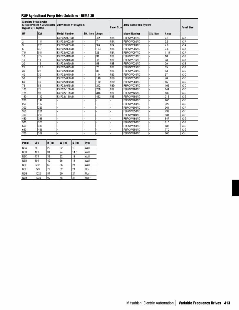
Mitsubishi Electric Automation | Variable Frequency Drives 413
F3IP Agricultural Pump Drive Solutions - NEMA 3R
Standard Product with Circuit Breaker & 3 Contactor Bypass VFD System
208V Based VFD SystemPanel Size
460V Based VFD SystemPanel Size
HP KW Model Number Stk. Item Amps Model Number Stk. Item Amps
1 1 F3IPC2V001ND - 4.2 N3A F3IPC4V001ND - 2.1 N3A2 1.5 F3IPC2V002ND - 7 N3A F3IPC4V002ND - 3.5 N3A3 2.2 F3IPC2V003ND - 9.6 N3A F3IPC4V003ND - 4.8 N3A5 3.7 F3IPC2V005ND - 15.2 N3A F3IPC4V005ND - 7.6 N3A7.5 5.5 F3IPC2V007ND - 23 N3A F3IPC4V007ND - 11.5 N3A10 7.5 F3IPC2V010ND - 31 N3B F3IPC4V010ND - 16 N3B15 11 F3IPC2V015ND - 45 N3B F3IPC4V015ND - 23 N3B20 15 F3IPC2V020ND - 58 N3B F3IPC4V020ND - 29 N3B25 18.5 F3IPC2V025ND - 70 N3C F3IPC4V025ND - 35 N3B30 22 F3IPC2V030ND - 85 N3C F3IPC4V030ND - 43 N3C40 30 F3IPC2V040ND - 114 N3C F3IPC4V040ND - 57 N3C50 37 F3IPC2V050ND - 140 N3D F3IPC4V050ND - 70 N3D60 45 F3IPC2V060ND - 170 N3D F3IPC4V060ND - 85 N3D75 55 F3IPC2V075ND - 212 N3D F3IPC4V075ND - 106 N3D100 75 F3IPC2V100ND - 288 N3E F3IPC4V100ND - 144 N3D125 93 F3IPC2V125ND - 346 N3E F3IPC4V125ND - 180 N3D150 112 F3IPC2V150ND - 432 N3E F3IPC4V150ND - 216 N3E200 149 - - - - F3IPC4V200ND - 260 N3E250 187 - - - - F3IPC4V250ND - 325 N3E300 225 - - - - F3IPC4V300ND - 361 N3F350 261 - - - - F3IPC4V350ND - 432 N3F400 299 - - - - F3IPC4V400ND - 481 N3F450 336 - - - - F3IPC4V450ND - 547 N3G500 373 - - - - F3IPC4V500ND - 610 N3G550 410 - - - - F3IPC4V550ND - 683 N3G650 485 - - - - F3IPC4V650ND - 770 N3G700 522 - - - - F3IPC4V700ND - 866 N3H
Panel Lbs H (in) W (in) D (in) Type
N3A 88 29 22 10 Wall
N3B 121 31 24 11.5 Wall
N3C 174 38 32 12 Wall
N3D 394 49 36 18 Wall
N3E 562 60 36 24 Wall
N3F 779 72 32 24 Floor
N3G 1025 84 39 24 Floor
N3H 1225 90 48 24 Floor
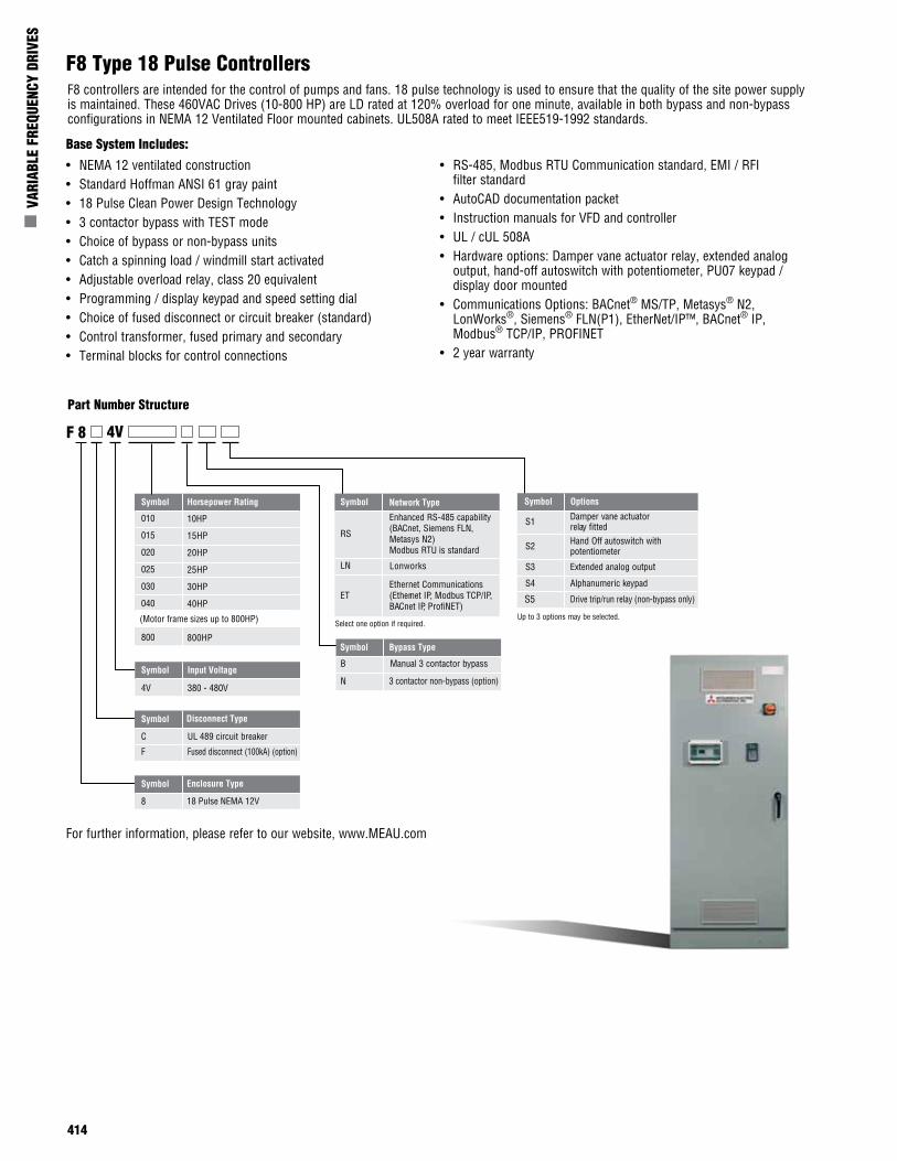
414
n V
ARIA
BLE
FREQ
UENC
Y DR
IVES
F8 Type 18 Pulse Controllers
• NEMA 12 ventilated construction• Standard Hoffman ANSI 61 gray paint• 18 Pulse Clean Power Design Technology• 3 contactor bypass with TEST mode• Choice of bypass or non-bypass units• Catch a spinning load / windmill start activated• Adjustable overload relay, class 20 equivalent• Programming / display keypad and speed setting dial• Choice of fused disconnect or circuit breaker (standard)• Control transformer, fused primary and secondary• Terminal blocks for control connections
• RS-485, Modbus RTU Communication standard, EMI / RFI filter standard
• AutoCAD documentation packet• Instruction manuals for VFD and controller• UL / cUL 508A• Hardware options: Damper vane actuator relay, extended analog
output, hand-off autoswitch with potentiometer, PU07 keypad / display door mounted
• Communications Options: BACnet® MS/TP, Metasys® N2, LonWorks®, Siemens® FLN(P1), EtherNet/IP™, BACnet® IP, Modbus® TCP/IP, PROFINET
• 2 year warranty
Symbol Horsepower Rating
010
015
020
025
030
040
800
10HP
15HP
20HP
25HP
30HP
40HP
800HP
Symbol Input Voltage
4V 380 - 480V
Symbol Bypass Type
B Manual 3 contactor bypass
N 3 contactor non-bypass (option)
Symbol
C UL 489 circuit breaker
F Fused disconnect (100kA) (option)
Symbol
8 18 Pulse NEMA 12V
F 8 4V
Symbol Options
S1 Damper vane actuator relay fitted
S2 Hand Off autoswitch with potentiometer
S3 Extended analog output
S4
S5
Alphanumeric keypad
Drive trip/run relay (non-bypass only)
Up to 3 options may be selected.
Disconnect Type
Enclosure Type
Symbol
RS
Enhanced RS-485 capability(BACnet, Siemens FLN, Metasys N2) Modbus RTU is standard
LN
ETEthernet Communications(Ethernet IP, Modbus TCP/IP,BACnet IP, ProfiNET)
Select one option if required.
Network Type
Lonworks
(Motor frame sizes up to 800HP)
F8 controllers are intended for the control of pumps and fans. 18 pulse technology is used to ensure that the quality of the site power supply is maintained. These 460VAC Drives (10-800 HP) are LD rated at 120% overload for one minute, available in both bypass and non-bypass configurations in NEMA 12 Ventilated Floor mounted cabinets. UL508A rated to meet IEEE519-1992 standards.
Base System Includes:
Part Number Structure
For further information, please refer to our website, www.MEAU.com
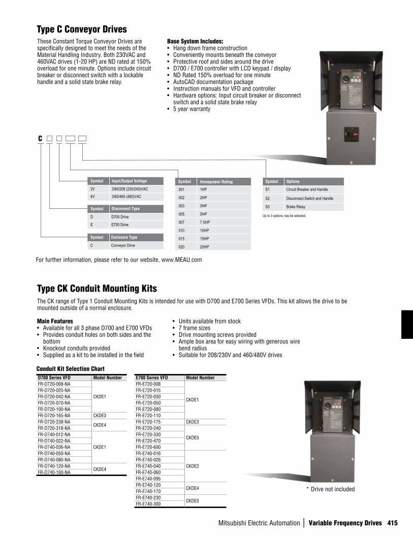
Mitsubishi Electric Automation | Variable Frequency Drives 415
Symbol Horsepower Rating
001
002
003
005
007
010
015
020
1HP
2HP
3HP
5HP
7.5HP
10HP
15HP
20HP
Symbol Input/Output Voltage
2V 3/60/208 (230/240)VAC
4V 3/60/460 (480)VAC
Symbol
D
E
D700 Drive
E700 Drive
Symbol
C Conveyor Drive
C
Disconnect Type
Enclosure Type
Symbol Options
S1 Circuit Breaker and Handle
S2 Disconnect Switch and Handle
S3 Brake Relay
Up to 3 options may be selected.
These Constant Torque Conveyor Drives are specifically designed to meet the needs of the Material Handling Industry. Both 230VAC and 460VAC drives (1-20 HP) are ND rated at 150% overload for one minute. Options include circuit breaker or disconnect switch with a lockable handle and a solid state brake relay.
Base System Includes:• Hang down frame construction• Conveniently mounts beneath the conveyor• Protective roof and sides around the drive• D700 / E700 controller with LCD keypad / display• ND Rated 150% overload for one minute• AutoCAD documentation package• Instruction manuals for VFD and controller• Hardware options: Input circuit breaker or disconnect
switch and a solid state brake relay• 5 year warranty
Type C Conveyor Drives
Main Features• Available for all 3 phase D700 and E700 VFDs• Provides conduit holes on both sides and the
bottom• Knockout conduits provided• Supplied as a kit to be installed in the field
• Units available from stock• 7 frame sizes• Drive mounting screws provided • Ample box area for easy wiring with generous wire
bend radius• Suitable for 208/230V and 460/480V drives
Conduit Kit Selection ChartD700 Series VFD Model NumberFR-D720-008-NA
CKDE1FR-D720-025-NAFR-D720-042-NAFR-D720-070-NAFR-D720-100-NAFR-D720-165-NA CKDE3FR-D720-238-NA
CKDE4FR-D720-318-NAFR-D740-012-NA
CKDE1FR-D740-022-NAFR-D740-036-NAFR-D740-050-NAFR-D740-080-NAFR-D740-120-NA
CKDE4FR-D740-160-NA
E700 Series VFD Model NumberFR-E720-008
CKDE1
FR-E720-015FR-E720-030FR-E720-050FR-E720-080FR-E720-110FR-E720-175 CKDE3FR-E720-240
CKDE5FR-E720-330FR-E720-470FR-E720-600FR-E740-016
CKDE2FR-E740-026FR-E740-040FR-E740-060FR-E740-095FR-E740-120
CKDE4FR-E740-170FR-E740-230
CKDE5FR-E740-300
For further information, please refer to our website, www.MEAU.com
Type CK Conduit Mounting KitsThe CK range of Type 1 Conduit Mounting Kits is intended for use with D700 and E700 Series VFDs. This kit allows the drive to be mounted outside of a normal enclosure.
* Drive not included
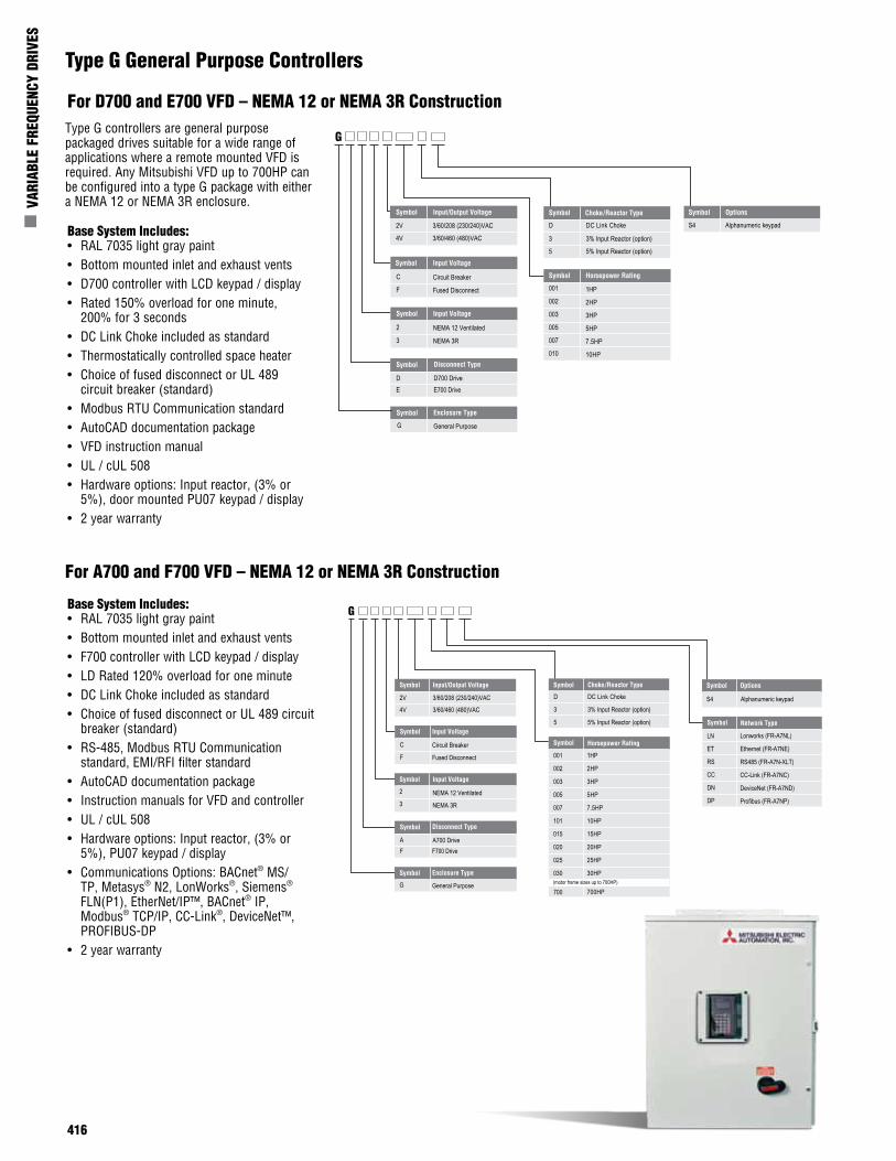
416
n V
ARIA
BLE
FREQ
UENC
Y DR
IVES
Symbol Horsepower Rating
001
002
003
005
007
010
1HP
2HP
3HP
5HP
7.5HP
10HP
Symbol Input Voltage
2
3
NEMA 12 Ventilated
NEMA 3R
Symbol Input Voltage
C
F
Circuit Breaker
Fused Disconnect
Symbol
D D700 DriveE E700 Drive
Symbol
G General Purpose
G
Symbol Options
S4 Alphanumeric keypad
Disconnect Type
Enclosure Type
Symbol Input/Output Voltage
2V 3/60/208 (230/240)VAC
4V 3/60/460 (480)VAC
Symbol
D DC Link Choke
3 3% Input Reactor (option)
5 5% Input Reactor (option)
Choke/Reactor Type
Type G controllers are general purpose packaged drives suitable for a wide range of applications where a remote mounted VFD is required. Any Mitsubishi VFD up to 700HP can be configured into a type G package with either a NEMA 12 or NEMA 3R enclosure.
Base System Includes:• RAL 7035 light gray paint• Bottom mounted inlet and exhaust vents• D700 controller with LCD keypad / display• Rated 150% overload for one minute,
200% for 3 seconds• DC Link Choke included as standard• Thermostatically controlled space heater• Choice of fused disconnect or UL 489
circuit breaker (standard)• Modbus RTU Communication standard• AutoCAD documentation package• VFD instruction manual• UL / cUL 508• Hardware options: Input reactor, (3% or
5%), door mounted PU07 keypad / display• 2 year warranty
Type G General Purpose Controllers
Symbol Horsepower Rating
001
002
003
005
007
101
015
020
025
030
1HP
2HP
3HP
5HP
7.5HP
10HP
15HP
20HP
25HP
30HP
LN
ET
RS
CC
DN
DP
Lonworks (FR-A7NL)
Ethernet (FR-A7NE)
RS485 (FR-A7N-XLT)
CC-Link (FR-A7NC)
DeviceNet (FR-A7ND)
Profibus (FR-A7NP)
Symbol
D DC Link Choke
3 3% Input Reactor (option)
5 5% Input Reactor (option) Symbol
Symbol Options
S4 Alphanumeric keypad
Choke/Reactor Type
Network Type
Symbol
G General Purpose
G
Enclosure Type
Symbol
A A700 DriveF F700 Drive
Disconnect Type
Symbol Input Voltage
2
3NEMA 12 Ventilated
NEMA 3R
Symbol Input Voltage
C
F
Circuit Breaker
Fused Disconnect
Symbol Input/Output Voltage
2V 3/60/208 (230/240)VAC
4V 3/60/460 (480)VAC
700 700HP(motor frame sizes up to 700HP)
Base System Includes:• RAL 7035 light gray paint• Bottom mounted inlet and exhaust vents• F700 controller with LCD keypad / display• LD Rated 120% overload for one minute• DC Link Choke included as standard• Choice of fused disconnect or UL 489 circuit
breaker (standard)• RS-485, Modbus RTU Communication
standard, EMI/RFI filter standard• AutoCAD documentation package• Instruction manuals for VFD and controller• UL / cUL 508• Hardware options: Input reactor, (3% or
5%), PU07 keypad / display• Communications Options: BACnet® MS/
TP, Metasys® N2, LonWorks®, Siemens®
FLN(P1), EtherNet/IP™, BACnet® IP, Modbus® TCP/IP, CC-Link®, DeviceNet™, PROFIBUS-DP
• 2 year warranty
For A700 and F700 VFD – NEMA 12 or NEMA 3R Construction
For D700 and E700 VFD – NEMA 12 or NEMA 3R Construction
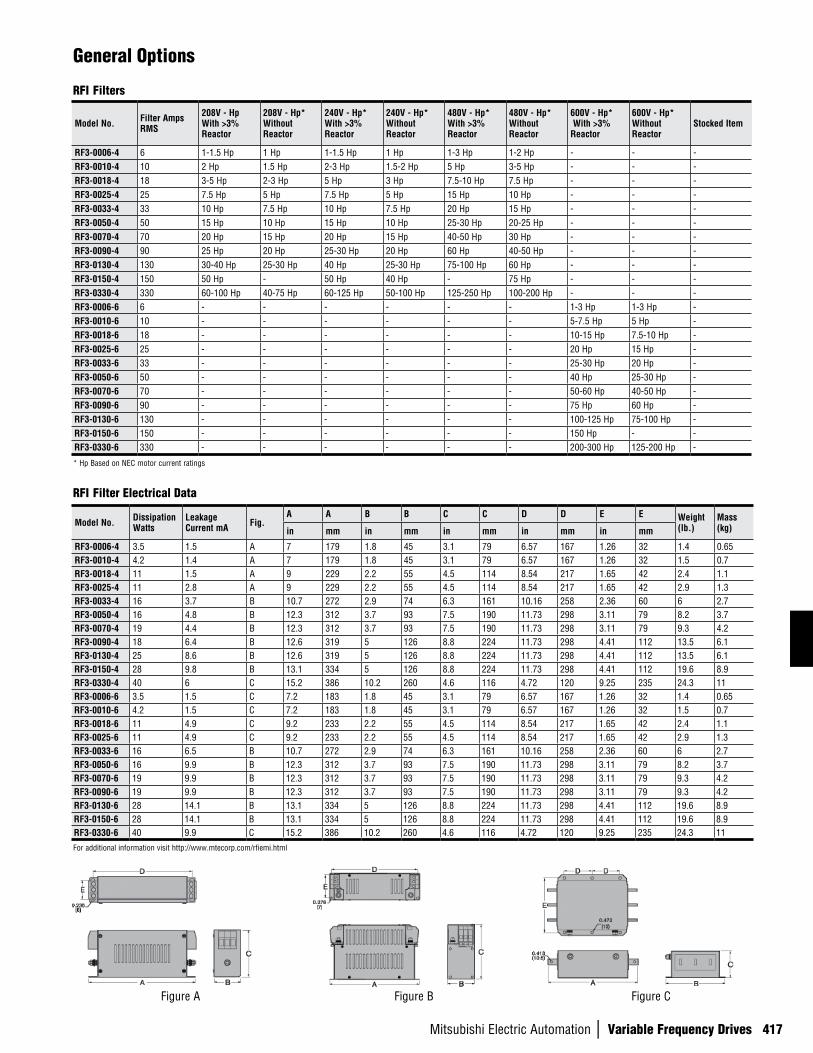
Mitsubishi Electric Automation | Variable Frequency Drives 417
General Options
RFI Filters
Model No. Filter Amps RMS
208V - Hp With >3% Reactor
208V - Hp* Without Reactor
240V - Hp* With >3% Reactor
240V - Hp* Without Reactor
480V - Hp* With >3% Reactor
480V - Hp* Without Reactor
600V - Hp* With >3% Reactor
600V - Hp* Without Reactor
Stocked Item
RF3-0006-4 6 1-1.5 Hp 1 Hp 1-1.5 Hp 1 Hp 1-3 Hp 1-2 Hp - - -RF3-0010-4 10 2 Hp 1.5 Hp 2-3 Hp 1.5-2 Hp 5 Hp 3-5 Hp - - -RF3-0018-4 18 3-5 Hp 2-3 Hp 5 Hp 3 Hp 7.5-10 Hp 7.5 Hp - - -RF3-0025-4 25 7.5 Hp 5 Hp 7.5 Hp 5 Hp 15 Hp 10 Hp - - -RF3-0033-4 33 10 Hp 7.5 Hp 10 Hp 7.5 Hp 20 Hp 15 Hp - - -RF3-0050-4 50 15 Hp 10 Hp 15 Hp 10 Hp 25-30 Hp 20-25 Hp - - -RF3-0070-4 70 20 Hp 15 Hp 20 Hp 15 Hp 40-50 Hp 30 Hp - - -RF3-0090-4 90 25 Hp 20 Hp 25-30 Hp 20 Hp 60 Hp 40-50 Hp - - -RF3-0130-4 130 30-40 Hp 25-30 Hp 40 Hp 25-30 Hp 75-100 Hp 60 Hp - - -RF3-0150-4 150 50 Hp - 50 Hp 40 Hp - 75 Hp - - -RF3-0330-4 330 60-100 Hp 40-75 Hp 60-125 Hp 50-100 Hp 125-250 Hp 100-200 Hp - - -RF3-0006-6 6 - - - - - - 1-3 Hp 1-3 Hp -RF3-0010-6 10 - - - - - - 5-7.5 Hp 5 Hp -RF3-0018-6 18 - - - - - - 10-15 Hp 7.5-10 Hp -RF3-0025-6 25 - - - - - - 20 Hp 15 Hp -RF3-0033-6 33 - - - - - - 25-30 Hp 20 Hp -RF3-0050-6 50 - - - - - - 40 Hp 25-30 Hp -RF3-0070-6 70 - - - - - - 50-60 Hp 40-50 Hp -RF3-0090-6 90 - - - - - - 75 Hp 60 Hp -RF3-0130-6 130 - - - - - - 100-125 Hp 75-100 Hp -RF3-0150-6 150 - - - - - - 150 Hp - -RF3-0330-6 330 - - - - - - 200-300 Hp 125-200 Hp -
* Hp Based on NEC motor current ratings
Model No. Dissipation Watts
Leakage Current mA Fig.
A A B B C C D D E E Weight (lb.)
Mass (kg)in mm in mm in mm in mm in mm
RF3-0006-4 3.5 1.5 A 7 179 1.8 45 3.1 79 6.57 167 1.26 32 1.4 0.65RF3-0010-4 4.2 1.4 A 7 179 1.8 45 3.1 79 6.57 167 1.26 32 1.5 0.7RF3-0018-4 11 1.5 A 9 229 2.2 55 4.5 114 8.54 217 1.65 42 2.4 1.1RF3-0025-4 11 2.8 A 9 229 2.2 55 4.5 114 8.54 217 1.65 42 2.9 1.3RF3-0033-4 16 3.7 B 10.7 272 2.9 74 6.3 161 10.16 258 2.36 60 6 2.7RF3-0050-4 16 4.8 B 12.3 312 3.7 93 7.5 190 11.73 298 3.11 79 8.2 3.7RF3-0070-4 19 4.4 B 12.3 312 3.7 93 7.5 190 11.73 298 3.11 79 9.3 4.2RF3-0090-4 18 6.4 B 12.6 319 5 126 8.8 224 11.73 298 4.41 112 13.5 6.1RF3-0130-4 25 8.6 B 12.6 319 5 126 8.8 224 11.73 298 4.41 112 13.5 6.1RF3-0150-4 28 9.8 B 13.1 334 5 126 8.8 224 11.73 298 4.41 112 19.6 8.9RF3-0330-4 40 6 C 15.2 386 10.2 260 4.6 116 4.72 120 9.25 235 24.3 11RF3-0006-6 3.5 1.5 C 7.2 183 1.8 45 3.1 79 6.57 167 1.26 32 1.4 0.65RF3-0010-6 4.2 1.5 C 7.2 183 1.8 45 3.1 79 6.57 167 1.26 32 1.5 0.7RF3-0018-6 11 4.9 C 9.2 233 2.2 55 4.5 114 8.54 217 1.65 42 2.4 1.1RF3-0025-6 11 4.9 C 9.2 233 2.2 55 4.5 114 8.54 217 1.65 42 2.9 1.3RF3-0033-6 16 6.5 B 10.7 272 2.9 74 6.3 161 10.16 258 2.36 60 6 2.7RF3-0050-6 16 9.9 B 12.3 312 3.7 93 7.5 190 11.73 298 3.11 79 8.2 3.7RF3-0070-6 19 9.9 B 12.3 312 3.7 93 7.5 190 11.73 298 3.11 79 9.3 4.2RF3-0090-6 19 9.9 B 12.3 312 3.7 93 7.5 190 11.73 298 3.11 79 9.3 4.2RF3-0130-6 28 14.1 B 13.1 334 5 126 8.8 224 11.73 298 4.41 112 19.6 8.9RF3-0150-6 28 14.1 B 13.1 334 5 126 8.8 224 11.73 298 4.41 112 19.6 8.9RF3-0330-6 40 9.9 C 15.2 386 10.2 260 4.6 116 4.72 120 9.25 235 24.3 11
RFI Filter Electrical Data
For additional information visit http://www.mtecorp.com/rfiemi.html
Figure A Figure B Figure C
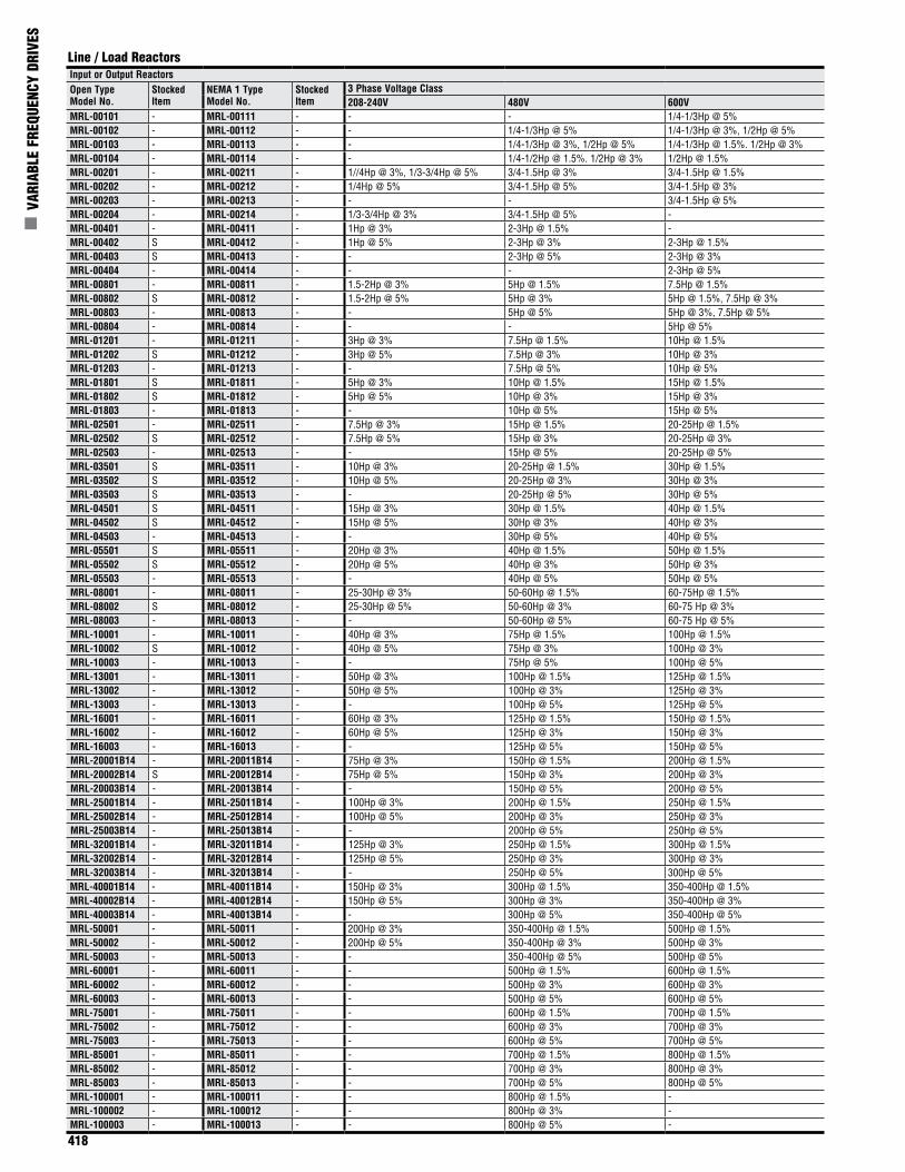
418
n V
ARIA
BLE
FREQ
UENC
Y DR
IVES
Input or Output ReactorsOpen Type Model No.
Stocked Item
NEMA 1 Type Model No.
Stocked Item
3 Phase Voltage Class208-240V 480V 600V
MRL-00101 - MRL-00111 - - - 1/4-1/3Hp @ 5%MRL-00102 - MRL-00112 - - 1/4-1/3Hp @ 5% 1/4-1/3Hp @ 3%, 1/2Hp @ 5%MRL-00103 - MRL-00113 - - 1/4-1/3Hp @ 3%, 1/2Hp @ 5% 1/4-1/3Hp @ 1.5%. 1/2Hp @ 3%MRL-00104 - MRL-00114 - - 1/4-1/2Hp @ 1.5%. 1/2Hp @ 3% 1/2Hp @ 1.5%MRL-00201 - MRL-00211 - 1//4Hp @ 3%, 1/3-3/4Hp @ 5% 3/4-1.5Hp @ 3% 3/4-1.5Hp @ 1.5%MRL-00202 - MRL-00212 - 1/4Hp @ 5% 3/4-1.5Hp @ 5% 3/4-1.5Hp @ 3%MRL-00203 - MRL-00213 - - - 3/4-1.5Hp @ 5%MRL-00204 - MRL-00214 - 1/3-3/4Hp @ 3% 3/4-1.5Hp @ 5% -MRL-00401 - MRL-00411 - 1Hp @ 3% 2-3Hp @ 1.5% -MRL-00402 S MRL-00412 - 1Hp @ 5% 2-3Hp @ 3% 2-3Hp @ 1.5%MRL-00403 S MRL-00413 - - 2-3Hp @ 5% 2-3Hp @ 3%MRL-00404 - MRL-00414 - - - 2-3Hp @ 5%MRL-00801 - MRL-00811 - 1.5-2Hp @ 3% 5Hp @ 1.5% 7.5Hp @ 1.5%MRL-00802 S MRL-00812 - 1.5-2Hp @ 5% 5Hp @ 3% 5Hp @ 1.5%, 7.5Hp @ 3%MRL-00803 - MRL-00813 - - 5Hp @ 5% 5Hp @ 3%, 7.5Hp @ 5%MRL-00804 - MRL-00814 - - - 5Hp @ 5%MRL-01201 - MRL-01211 - 3Hp @ 3% 7.5Hp @ 1.5% 10Hp @ 1.5%MRL-01202 S MRL-01212 - 3Hp @ 5% 7.5Hp @ 3% 10Hp @ 3%MRL-01203 - MRL-01213 - - 7.5Hp @ 5% 10Hp @ 5%MRL-01801 S MRL-01811 - 5Hp @ 3% 10Hp @ 1.5% 15Hp @ 1.5%MRL-01802 S MRL-01812 - 5Hp @ 5% 10Hp @ 3% 15Hp @ 3%MRL-01803 - MRL-01813 - - 10Hp @ 5% 15Hp @ 5%MRL-02501 - MRL-02511 - 7.5Hp @ 3% 15Hp @ 1.5% 20-25Hp @ 1.5%MRL-02502 S MRL-02512 - 7.5Hp @ 5% 15Hp @ 3% 20-25Hp @ 3%MRL-02503 - MRL-02513 - - 15Hp @ 5% 20-25Hp @ 5%MRL-03501 S MRL-03511 - 10Hp @ 3% 20-25Hp @ 1.5% 30Hp @ 1.5%MRL-03502 S MRL-03512 - 10Hp @ 5% 20-25Hp @ 3% 30Hp @ 3%MRL-03503 S MRL-03513 - - 20-25Hp @ 5% 30Hp @ 5%MRL-04501 S MRL-04511 - 15Hp @ 3% 30Hp @ 1.5% 40Hp @ 1.5%MRL-04502 S MRL-04512 - 15Hp @ 5% 30Hp @ 3% 40Hp @ 3%MRL-04503 - MRL-04513 - - 30Hp @ 5% 40Hp @ 5%MRL-05501 S MRL-05511 - 20Hp @ 3% 40Hp @ 1.5% 50Hp @ 1.5%MRL-05502 S MRL-05512 - 20Hp @ 5% 40Hp @ 3% 50Hp @ 3%MRL-05503 - MRL-05513 - - 40Hp @ 5% 50Hp @ 5%MRL-08001 - MRL-08011 - 25-30Hp @ 3% 50-60Hp @ 1.5% 60-75Hp @ 1.5%MRL-08002 S MRL-08012 - 25-30Hp @ 5% 50-60Hp @ 3% 60-75 Hp @ 3%MRL-08003 - MRL-08013 - - 50-60Hp @ 5% 60-75 Hp @ 5%MRL-10001 - MRL-10011 - 40Hp @ 3% 75Hp @ 1.5% 100Hp @ 1.5%MRL-10002 S MRL-10012 - 40Hp @ 5% 75Hp @ 3% 100Hp @ 3%MRL-10003 - MRL-10013 - - 75Hp @ 5% 100Hp @ 5%MRL-13001 - MRL-13011 - 50Hp @ 3% 100Hp @ 1.5% 125Hp @ 1.5%MRL-13002 - MRL-13012 - 50Hp @ 5% 100Hp @ 3% 125Hp @ 3%MRL-13003 - MRL-13013 - - 100Hp @ 5% 125Hp @ 5%MRL-16001 - MRL-16011 - 60Hp @ 3% 125Hp @ 1.5% 150Hp @ 1.5%MRL-16002 - MRL-16012 - 60Hp @ 5% 125Hp @ 3% 150Hp @ 3%MRL-16003 - MRL-16013 - - 125Hp @ 5% 150Hp @ 5%MRL-20001B14 - MRL-20011B14 - 75Hp @ 3% 150Hp @ 1.5% 200Hp @ 1.5%MRL-20002B14 S MRL-20012B14 - 75Hp @ 5% 150Hp @ 3% 200Hp @ 3%MRL-20003B14 - MRL-20013B14 - - 150Hp @ 5% 200Hp @ 5%MRL-25001B14 - MRL-25011B14 - 100Hp @ 3% 200Hp @ 1.5% 250Hp @ 1.5%MRL-25002B14 - MRL-25012B14 - 100Hp @ 5% 200Hp @ 3% 250Hp @ 3%MRL-25003B14 - MRL-25013B14 - - 200Hp @ 5% 250Hp @ 5%MRL-32001B14 - MRL-32011B14 - 125Hp @ 3% 250Hp @ 1.5% 300Hp @ 1.5%MRL-32002B14 - MRL-32012B14 - 125Hp @ 5% 250Hp @ 3% 300Hp @ 3%MRL-32003B14 - MRL-32013B14 - - 250Hp @ 5% 300Hp @ 5%MRL-40001B14 - MRL-40011B14 - 150Hp @ 3% 300Hp @ 1.5% 350-400Hp @ 1.5%MRL-40002B14 - MRL-40012B14 - 150Hp @ 5% 300Hp @ 3% 350-400Hp @ 3%MRL-40003B14 - MRL-40013B14 - - 300Hp @ 5% 350-400Hp @ 5%MRL-50001 - MRL-50011 - 200Hp @ 3% 350-400Hp @ 1.5% 500Hp @ 1.5%MRL-50002 - MRL-50012 - 200Hp @ 5% 350-400Hp @ 3% 500Hp @ 3%MRL-50003 - MRL-50013 - - 350-400Hp @ 5% 500Hp @ 5%MRL-60001 - MRL-60011 - - 500Hp @ 1.5% 600Hp @ 1.5%MRL-60002 - MRL-60012 - - 500Hp @ 3% 600Hp @ 3%MRL-60003 - MRL-60013 - - 500Hp @ 5% 600Hp @ 5%MRL-75001 - MRL-75011 - - 600Hp @ 1.5% 700Hp @ 1.5%MRL-75002 - MRL-75012 - - 600Hp @ 3% 700Hp @ 3%MRL-75003 - MRL-75013 - - 600Hp @ 5% 700Hp @ 5%MRL-85001 - MRL-85011 - - 700Hp @ 1.5% 800Hp @ 1.5%MRL-85002 - MRL-85012 - - 700Hp @ 3% 800Hp @ 3%MRL-85003 - MRL-85013 - - 700Hp @ 5% 800Hp @ 5%MRL-100001 - MRL-100011 - - 800Hp @ 1.5% -MRL-100002 - MRL-100012 - - 800Hp @ 3% -MRL-100003 - MRL-100013 - - 800Hp @ 5% -
Line / Load Reactors
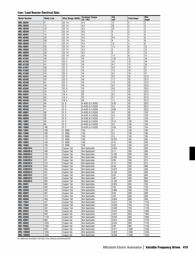
Mitsubishi Electric Automation | Variable Frequency Drives 419
Model Number Watts Loss Wire Range (AWG) Terminal Torque (in / lbs)
Ind. mH Fund Amps Max
Amps MRL-00201 8 22 14 4.5 12 2 3MRL-00202 12 22 14 4.5 20 2 3MRL-00203 16 22 14 4.5 32 2 3MRL-00204 11 22 14 4.5 6 2 3MRL-00401 15 22 14 4.5 3 4 6MRL-00402 20 22 14 4.5 6.5 4 6MRL-00403 20 22 14 4.5 9 4 6MRL-00404 21 22 14 4.5 12 4 6MRL-00801 20 22 14 4.5 1.5 8 12MRL-00802 29 22 14 4.5 3 8 12MRL-00803 26 22 14 4.5 5 8 12MRL-00804 28 22 14 4.5 7.5 8 12MRL-01201 26 22 5 16 1.25 12 18MRL-01202 31 22 5 16 2.5 12 18MRL-01203 41 22 5 16 4.2 12 18MRL-01801 36 22 5 16 0.8 18 27MRL-01802 43 22 5 16 1.5 18 27MRL-01803 43 22 5 16 2.5 18 27MRL-02501 48 22 5 16 0.5 25 37.5MRL-02502 52 22 5 16 1.2 25 37.5MRL-02503 61 22 5 16 1.8 25 37.5MRL-03501 49 22 5 16 0.4 35 52.5MRL-03502 54 22 5 16 0.8 35 52.5MRL-03503 54 18 4 20 1.2 35 52.5MRL-04501 54 18 4 20 0.3 45 67.5MRL-04502 62 18 4 20 0.7 45 67.5MRL-04503 65 18 4 20 1.2 45 67.5MRL-05501 64 6 0 6-4(45) & 2-0(50) 0.25 55 82.5MRL-05502 67 6 0 6-4(45) & 2-0(50) 0.5 55 82.5MRL-05503 71 6 0 6-4(45) & 2-0(50) 0.85 55 82.5MRL-08001 82 6 0 6-4(45) & 2-0(50) 0.2 80 120MRL-08002 86 6 0 6-4(45) & 2-0(50) 0.4 80 120MRL-08003 96 6 0 6-4(45) & 2-0(50) 0.7 80 120MRL-10001 94 6 0 6-4(45) & 2-0(50) 0.15 100 150MRL-10002 84 6 0 6-4(45) & 2-0(50) 0.3 100 150MRL-10003 108 6 0 6-4(45) & 2-0(50) 0.45 100 150MRL-13001 108 2 0000 150 0.1 130 195MRL-13002 180 2 0000 150 0.2 130 195MRL-13003 128 2 0000 150 0.3 130 195MRL-16001 116 2 0000 150 0.075 160 240MRL-16002 149 2 0000 150 0.15 160 240MRL-16003 138 2 0000 150 0.23 160 240MRL-20001B14 124 Copper Tab Not Applicable 0.055 200 300MRL-20002B14 168 Copper Tab Not Applicable 0.11 200 300MRL-20003B14 146 Copper Tab Not Applicable 0.185 200 300MRL-25001B14 154 Copper Tab Not Applicable 0.045 250 375MRL-25002B14 231 Copper Tab Not Applicable 0.09 250 375MRL-25003B14 219 Copper Tab Not Applicable 0.15 250 375MRL-32001B14 224 Copper Tab Not Applicable 0.04 320 480MRL-32002B14 264 Copper Tab Not Applicable 0.075 320 480MRL-32003B14 351 Copper Tab Not Applicable 0.125 320 480MRL-40001B14 231 Copper Tab Not Applicable 0.03 400 600MRL-40002B14 333 Copper Tab Not Applicable 0.06 400 600MRL-40003B14 293 Copper Tab Not Applicable 0.105 400 600MRL-50001 266 Copper Tab Not Applicable 0.025 500 750MRL-50002 340 Copper Tab Not Applicable 0.05 500 750MRL-50003 422 Copper Tab Not Applicable 0.085 500 750MRL-60001 307 Copper Tab Not Applicable 0.02 600 900MRL-60002 414 Copper Tab Not Applicable 0.04 600 900MRL-60003 406 Copper Tab Not Applicable 0.065 600 900MRL-75001 427 Copper Tab Not Applicable 0.015 750 1125MRL-75002 630 Copper Tab Not Applicable 0.029 750 1125MRL-75003 552 Copper Tab Not Applicable 0.048 750 1125MRL-85001 798 Copper tab Not Applicable 0.015 850 1063MRL-85002 930 Copper tab Not Applicable 0.027 850 1063MRL-85003 1133 Copper tab Not Applicable 0.042 850 1063MRL-90001 860 Copper tab Not Applicable 0.013 900 1125MRL-90002 1020 Copper tab Not Applicable 0.025 900 1125MRL-90003 1365 Copper tab Not Applicable 0.04 900 1125MRL-100001 940 Copper tab Not Applicable 0.011 1000 1250MRL-100002 1090 Copper tab Not Applicable 0.022 1000 1250MRL-100003 1500 Copper tab Not Applicable 0.038 1000 1250
Line / Load Reactor Electrical Data
For additional information visit http://www.mtecorp.com/lineload.html
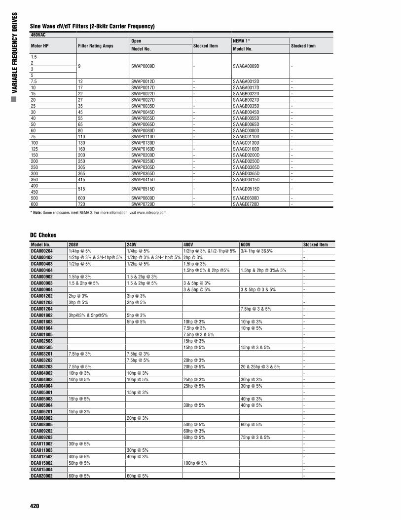
420
n V
ARIA
BLE
FREQ
UENC
Y DR
IVES
Model No. 208V 240V 480V 600V Stocked ItemDCA000204 1/4hp @ 5% 1/4hp @ 5% 1/2hp @ 3% &1/2-1hp@ 5% 3/4-1hp @ 3&5% -DCA000402 1/2hp @ 3% & 3/4-1hp@ 5% 1/2hp @ 3% & 3/4-1hp@ 5% 2hp @ 3% -DCA000403 1/2hp @ 5% 1/2hp @ 5% 1.5hp @ 3% -DCA000404 1.5hp @ 5% & 2hp @5% 1.5hp & 2hp @ 3%& 5% -DCA000902 1.5hp @ 3% 1.5 & 2hp @ 3% -DCA000903 1.5 & 2hp @ 5% 1.5 & 2hp @ 5% 3 & 5hp @ 3% -DCA000904 3 & 5hp @ 5% 3 & 5hp @ 3 & 5% -DCA001202 2hp @ 3% 3hp @ 3% -DCA001203 3hp @ 5% 3hp @ 5% -DCA001204 7.5hp @ 3 & 5% -DCA001802 3hp@3% & 5hp@5% 5hp @ 3% -DCA001803 5hp @ 5% 10hp @ 3% 10hp @ 3% -DCA001804 7.5hp @ 3% 10hp @ 5% -DCA001805 7.5hp @ 3 & 5% -DCA002503 15hp @ 3% -DCA002505 15hp @ 5% 15hp @ 3 & 5% -DCA003201 7.5hp @ 3% 7.5hp @ 3% -DCA003202 7.5hp @ 5% 20hp @ 3% -DCA003203 7.5hp @ 5% 20hp @ 5% 20 & 25hp @ 3 & 5% -DCA004002 10hp @ 3% 10hp @ 3% -DCA004003 10hp @ 5% 10hp @ 5% 25hp @ 3% 30hp @ 3% -DCA004004 25hp @ 5% 30hp @ 5% -DCA005001 15hp @ 3% -DCA005003 15hp @ 5% 40hp @ 3% -DCA005004 30hp @ 5% 40hp @ 5% -DCA006201 15hp @ 3% -DCA008002 20hp @ 3% -DCA008005 50hp @ 5% 60hp @ 5% -DCA009202 60hp @ 3% -DCA009203 60hp @ 5% 75hp @ 3 & 5% -DCA011002 30hp @ 5% -DCA011003 30hp @ 5% -DCA012502 40hp @ 5% 40hp @ 3% -DCA015002 50hp @ 5% 100hp @ 5% -DCA015004 -DCA020002 60hp @ 5% 60hp @ 5% -
DC Chokes
Sine Wave dV/dT Filters (2-8kHz Carrier Frequency)460VAC
Motor HP Filter Rating Amps Open
Stocked ItemNEMA 1*
Stocked ItemModel No. Model No.
1.5
9 SWAP0009D - SWAGA0009D -2357.5 12 SWAP0012D - SWAGA0012D -10 17 SWAP0017D - SWAGA0017D -15 22 SWAP0022D - SWAGB0022D -20 27 SWAP0027D - SWAGB0027D -25 35 SWAP0035D - SWAGB0035D -30 45 SWAP0045D - SWAGB0045D -40 55 SWAP0055D - SWAGB0055D -50 65 SWAP0065D - SWAGB0065D -60 80 SWAP0080D - SWAGC0080D -75 110 SWAP0110D - SWAGC0110D -100 130 SWAP0130D - SWAGC0130D -125 160 SWAP0160D - SWAGC0160D -150 200 SWAP0200D - SWAGD0200D -200 250 SWAP0250D - SWAGD0250D -250 305 SWAP0305D - SWAGD0305D -300 365 SWAP0365D - SWAGD0365D -350 415 SWAP0415D - SWAGD0415D -400
515 SWAP0515D - SWAGD0515D -450500 600 SWAP0600D - SWAGE0600D -600 720 SWAP0720D - SWAGE0720D -
* Note: Some enclosures meet NEMA 2. For more information, visit www.mtecorp.com
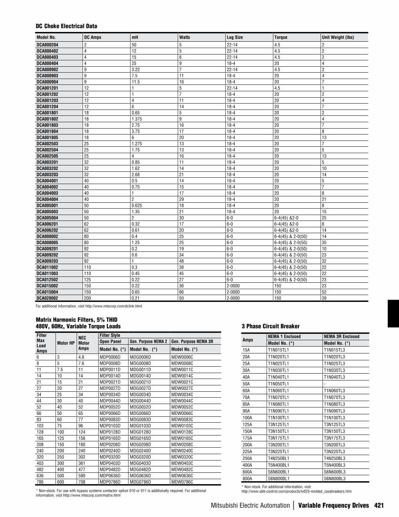
Mitsubishi Electric Automation | Variable Frequency Drives 421
DC Choke Electrical Data
For additional information, visit http://www.mtecorp.com/dclink.html
Filter Max Load Amps
Motor HP NEC Motor Amps
Filter Style Open Panel Gen. Purpose NEMA 2 Gen. Purpose NEMA 3R
Model No. (*) Model No. (*) Model No. (*)
6 3 4.8 MDP0006D MDG0006D MDW0006C 8 5 7.6 MDP0008D MDG0008D MDW0008C 11 7.5 11 MDP0011D MDG0011D MDW0011C 14 10 14 MDP0014D MDG0014D MDW0014C 21 15 21 MDP0021D MDG0021D MDW0021C 27 20 27 MDP0027D MDG0027D MDW0027C 34 25 34 MDP0034D MDG0034D MDW0034C 44 30 40 MDP0044D MDG0044D MDW0044C 52 40 52 MDP0052D MDG0052D MDW0052C 66 50 65 MDP0066D MDG0066D MDW0066C 83 60 77 MDP0083D MDG0083D MDW0083C 103 75 96 MDP0103D MDG0103D MDW0103C 128 100 124 MDP0128D MDG0128D MDW0128C 165 125 156 MDP0165D MDG0165D MDW0165C 208 150 180 MDP0208D MDG0208D MDW0208C 240 200 240 MDP0240D MDG0240D MDW0240C 320 250 302 MDP0320D MDG0320D MDW0320C 403 300 361 MDP0403D MDG0403D MDW0403C 482 400 477 MDP0482D MDG0482D MDW0482C 636 500 590 MDP0636D MDG0636D MDW0636C 786 600 708 MDP0786D MDG0786D MDW0786C
Matrix Harmonic Filters, 5% THID 480V, 60Hz, Variable Torque Loads 3 Phase Circuit Breaker
AmpsNEMA 1 Enclosed NEMA 3R EnclosedModel No. (*) Model No. (*)
15A T1N015TL1 T1N015TL320A T1N020TL1 T1N020TL325A T1N025TL1 T1N025TL330A T1N030TL1 T1N030TL340A T1N040TL1 T1N040TL350A T1N050TL1 -60A T1N060TL1 T1N060TL370A T1N070TL1 T1N070TL380A T1N080TL1 T1N080TL390A T1N090TL1 T1N090TL3100A T1N100TL1 T1N100TL3125A T3N125TL1 T3N125TL3150A T3N150TL1 T3N150TL3175A T3N175TL1 T3N175TL3200A T3N200TL1 T3N200TL3225A T3N225TL1 T3N225TL3250A T4N250BL1 T4N250BL3400A T5N400BL1 T5N400BL3600A S6N600BL1 S6N600BL3800A S6N800BL1 S6N800BL3
* Non-stock. For additional information, visit http://www.abb-control.com/products/lv023-molded_casebreakers.htm* Non-stock. For use with bypass systems contactor option 010 or 011 is additionally required. For additional
information, visit http://www.mtecorp.com/matrix.html
Model No. DC Amps mH Watts Lug Size Torque Unit Weight (lbs)
DCA000204 2 50 5 22-14 4.5 2DCA000402 4 12 5 22-14 4.5 2DCA000403 4 15 6 22-14 4.5 2DCA000404 4 25 9 18-4 20 4DCA000902 9 3.22 7 22-14 4.5 2DCA000903 9 7.5 11 18-4 20 4DCA000904 9 11.5 16 18-4 20 7DCA001201 12 1 5 22-14 4.5 1DCA001202 12 1 7 18-4 20 2DCA001203 12 4 11 18-4 20 4DCA001204 12 6 14 18-4 20 7DCA001801 18 0.65 5 18-4 20 2DCA001802 18 1.375 9 18-4 20 4DCA001803 18 2.75 16 18-4 20 7DCA001804 18 3.75 17 18-4 20 8DCA001805 18 6 20 18-4 20 13DCA002503 25 1.275 13 18-4 20 7DCA002504 25 1.75 13 18-4 20 5DCA002505 25 4 16 18-4 20 13DCA003201 32 0.85 11 18-4 20 5DCA003202 32 1.62 14 18-4 20 10DCA003203 32 2.68 21 18-4 20 14DCA004001 40 0.5 14 18-4 20 5DCA004002 40 0.75 15 18-4 20 7DCA004003 40 1 17 18-4 20 8DCA004004 40 2 29 18-4 20 21DCA005001 50 0.625 18 18-4 20 8DCA005003 50 1.35 21 18-4 20 15DCA005004 50 2 30 6-0 6-4(45) &2-0 25DCA006201 62 0.32 17 6-0 6-4(45) &2-0 8DCA006202 62 0.61 20 6-0 6-4(45) &2-0 14DCA008002 80 0.4 25 6-0 6-4(45) & 2-0(50) 14DCA008005 80 1.25 25 6-0 6-4(45) & 2-0(50) 35DCA009201 92 0.2 19 6-0 6-4(45) & 2-0(50) 10DCA009202 92 0.6 34 6-0 6-4(45) & 2-0(50) 23DCA009203 92 1 48 6-0 6-4(45) & 2-0(50) 32DCA011002 110 0.3 38 6-0 6-4(45) & 2-0(50) 22DCA011003 110 0.45 45 6-0 6-4(45) & 2-0(50) 22DCA012502 125 0.22 27 6-0 6-4(45) & 2-0(50) 23DCA015002 150 0.22 36 2-0000 150 23DCA015004 150 0.65 66 2-0000 150 52DCA020002 200 0.21 50 2-0000 150 39
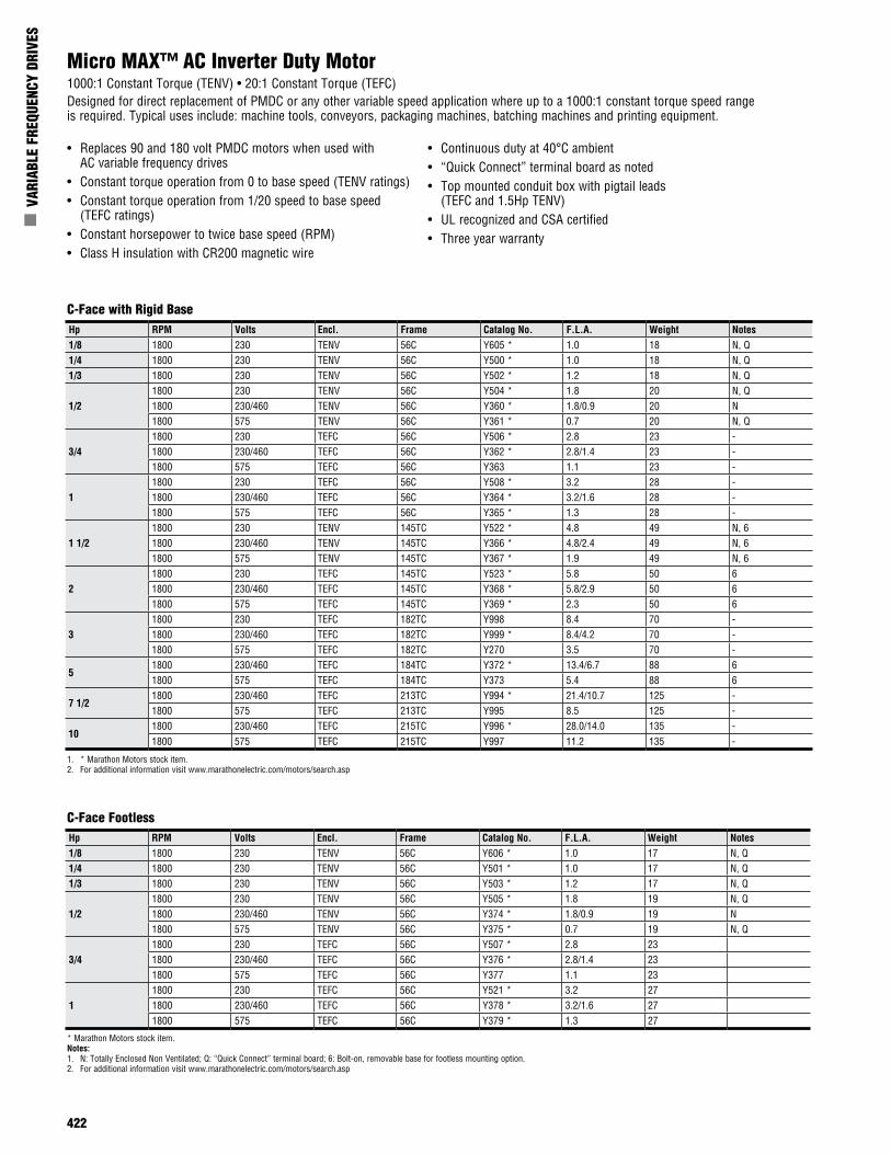
422
n V
ARIA
BLE
FREQ
UENC
Y DR
IVES
Micro MAX™ AC Inverter Duty Motor1000:1 Constant Torque (TENV) • 20:1 Constant Torque (TEFC)Designed for direct replacement of PMDC or any other variable speed application where up to a 1000:1 constant torque speed range is required. Typical uses include: machine tools, conveyors, packaging machines, batching machines and printing equipment.
• Replaces 90 and 180 volt PMDC motors when used with AC variable frequency drives
• Constant torque operation from 0 to base speed (TENV ratings)• Constant torque operation from 1/20 speed to base speed
(TEFC ratings)• Constant horsepower to twice base speed (RPM)• Class H insulation with CR200 magnetic wire
• Continuous duty at 40°C ambient• “Quick Connect” terminal board as noted• Top mounted conduit box with pigtail leads
(TEFC and 1.5Hp TENV)• UL recognized and CSA certified• Three year warranty
C-Face with Rigid Base
1. * Marathon Motors stock item.2. For additional information visit www.marathonelectric.com/motors/search.asp
C-Face FootlessHp RPM Volts Encl. Frame Catalog No. F.L.A. Weight Notes1/8 1800 230 TENV 56C Y606 * 1.0 17 N, Q1/4 1800 230 TENV 56C Y501 * 1.0 17 N, Q1/3 1800 230 TENV 56C Y503 * 1.2 17 N, Q
1/21800 230 TENV 56C Y505 * 1.8 19 N, Q1800 230/460 TENV 56C Y374 * 1.8/0.9 19 N1800 575 TENV 56C Y375 * 0.7 19 N, Q
3/41800 230 TEFC 56C Y507 * 2.8 231800 230/460 TEFC 56C Y376 * 2.8/1.4 231800 575 TEFC 56C Y377 1.1 23
11800 230 TEFC 56C Y521 * 3.2 271800 230/460 TEFC 56C Y378 * 3.2/1.6 271800 575 TEFC 56C Y379 * 1.3 27
* Marathon Motors stock item.Notes:1. N: Totally Enclosed Non Ventilated; Q: “Quick Connect” terminal board; 6: Bolt-on, removable base for footless mounting option.2. For additional information visit www.marathonelectric.com/motors/search.asp
Hp RPM Volts Encl. Frame Catalog No. F.L.A. Weight Notes1/8 1800 230 TENV 56C Y605 * 1.0 18 N, Q1/4 1800 230 TENV 56C Y500 * 1.0 18 N, Q1/3 1800 230 TENV 56C Y502 * 1.2 18 N, Q
1/21800 230 TENV 56C Y504 * 1.8 20 N, Q1800 230/460 TENV 56C Y360 * 1.8/0.9 20 N1800 575 TENV 56C Y361 * 0.7 20 N, Q
3/41800 230 TEFC 56C Y506 * 2.8 23 -1800 230/460 TEFC 56C Y362 * 2.8/1.4 23 -1800 575 TEFC 56C Y363 1.1 23 -
11800 230 TEFC 56C Y508 * 3.2 28 -1800 230/460 TEFC 56C Y364 * 3.2/1.6 28 -1800 575 TEFC 56C Y365 * 1.3 28 -
1 1/21800 230 TENV 145TC Y522 * 4.8 49 N, 61800 230/460 TENV 145TC Y366 * 4.8/2.4 49 N, 61800 575 TENV 145TC Y367 * 1.9 49 N, 6
21800 230 TEFC 145TC Y523 * 5.8 50 61800 230/460 TEFC 145TC Y368 * 5.8/2.9 50 61800 575 TEFC 145TC Y369 * 2.3 50 6
31800 230 TEFC 182TC Y998 8.4 70 -1800 230/460 TEFC 182TC Y999 * 8.4/4.2 70 -1800 575 TEFC 182TC Y270 3.5 70 -
51800 230/460 TEFC 184TC Y372 * 13.4/6.7 88 61800 575 TEFC 184TC Y373 5.4 88 6
7 1/21800 230/460 TEFC 213TC Y994 * 21.4/10.7 125 -1800 575 TEFC 213TC Y995 8.5 125 -
101800 230/460 TEFC 215TC Y996 * 28.0/14.0 135 -1800 575 TEFC 215TC Y997 11.2 135 -
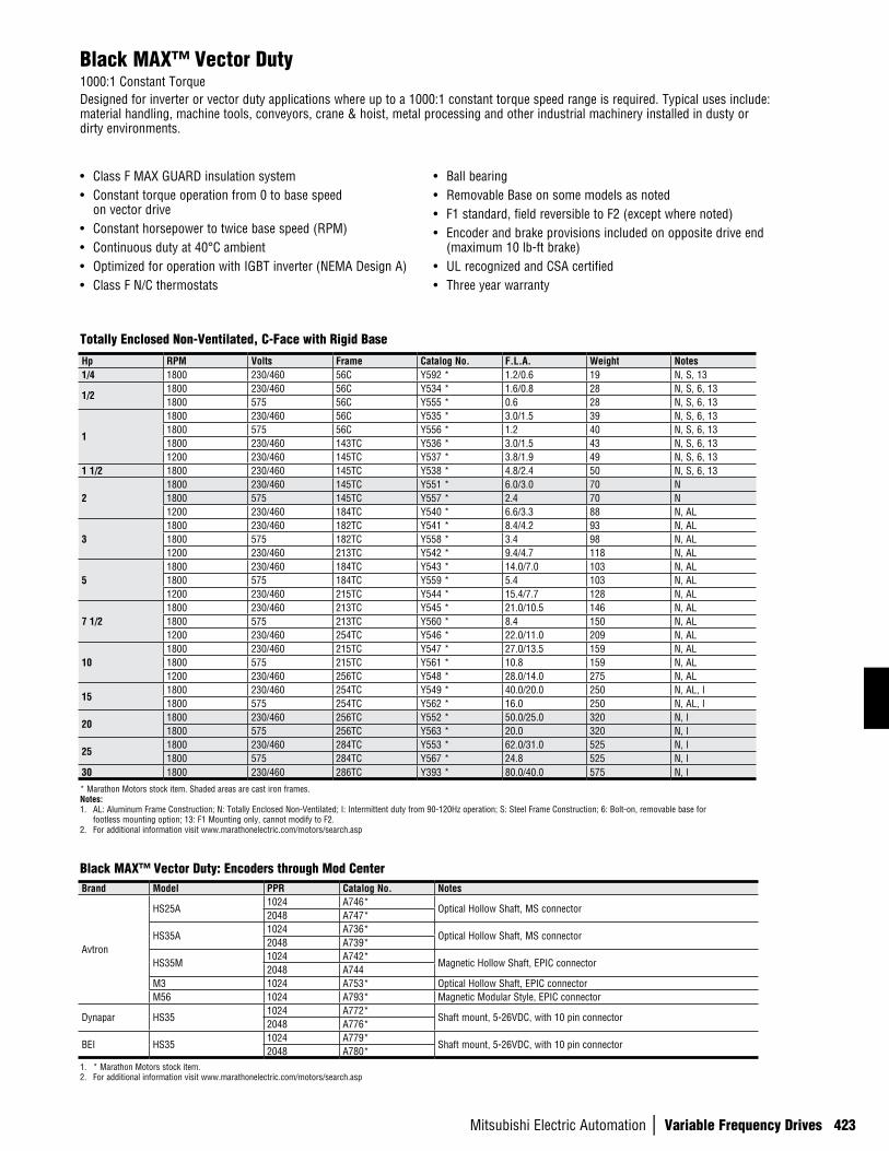
Mitsubishi Electric Automation | Variable Frequency Drives 423
Black MAX™ Vector Duty1000:1 Constant TorqueDesigned for inverter or vector duty applications where up to a 1000:1 constant torque speed range is required. Typical uses include: material handling, machine tools, conveyors, crane & hoist, metal processing and other industrial machinery installed in dusty or dirty environments.
• Class F MAX GUARD insulation system• Constant torque operation from 0 to base speed
on vector drive• Constant horsepower to twice base speed (RPM)• Continuous duty at 40°C ambient• Optimized for operation with IGBT inverter (NEMA Design A)• Class F N/C thermostats
• Ball bearing• Removable Base on some models as noted• F1 standard, field reversible to F2 (except where noted)• Encoder and brake provisions included on opposite drive end
(maximum 10 lb-ft brake)• UL recognized and CSA certified• Three year warranty
Totally Enclosed Non-Ventilated, C-Face with Rigid Base
Black MAX™ Vector Duty: Encoders through Mod Center
Hp RPM Volts Frame Catalog No. F.L.A. Weight Notes1/4 1800 230/460 56C Y592 * 1.2/0.6 19 N, S, 13
1/21800 230/460 56C Y534 * 1.6/0.8 28 N, S, 6, 131800 575 56C Y555 * 0.6 28 N, S, 6, 13
1
1800 230/460 56C Y535 * 3.0/1.5 39 N, S, 6, 131800 575 56C Y556 * 1.2 40 N, S, 6, 131800 230/460 143TC Y536 * 3.0/1.5 43 N, S, 6, 131200 230/460 145TC Y537 * 3.8/1.9 49 N, S, 6, 13
1 1/2 1800 230/460 145TC Y538 * 4.8/2.4 50 N, S, 6, 13
21800 230/460 145TC Y551 * 6.0/3.0 70 N1800 575 145TC Y557 * 2.4 70 N1200 230/460 184TC Y540 * 6.6/3.3 88 N, AL
31800 230/460 182TC Y541 * 8.4/4.2 93 N, AL1800 575 182TC Y558 * 3.4 98 N, AL1200 230/460 213TC Y542 * 9.4/4.7 118 N, AL
51800 230/460 184TC Y543 * 14.0/7.0 103 N, AL1800 575 184TC Y559 * 5.4 103 N, AL1200 230/460 215TC Y544 * 15.4/7.7 128 N, AL
7 1/21800 230/460 213TC Y545 * 21.0/10.5 146 N, AL1800 575 213TC Y560 * 8.4 150 N, AL1200 230/460 254TC Y546 * 22.0/11.0 209 N, AL
101800 230/460 215TC Y547 * 27.0/13.5 159 N, AL1800 575 215TC Y561 * 10.8 159 N, AL1200 230/460 256TC Y548 * 28.0/14.0 275 N, AL
151800 230/460 254TC Y549 * 40.0/20.0 250 N, AL, I1800 575 254TC Y562 * 16.0 250 N, AL, I
201800 230/460 256TC Y552 * 50.0/25.0 320 N, I1800 575 256TC Y563 * 20.0 320 N, I
251800 230/460 284TC Y553 * 62.0/31.0 525 N, I1800 575 284TC Y567 * 24.8 525 N, I
30 1800 230/460 286TC Y393 * 80.0/40.0 575 N, I
* Marathon Motors stock item. Shaded areas are cast iron frames.Notes:1. AL: Aluminum Frame Construction; N: Totally Enclosed Non-Ventilated; I: Intermittent duty from 90-120Hz operation; S: Steel Frame Construction; 6: Bolt-on, removable base for
footless mounting option; 13: F1 Mounting only, cannot modify to F2.2. For additional information visit www.marathonelectric.com/motors/search.asp
1. * Marathon Motors stock item.2. For additional information visit www.marathonelectric.com/motors/search.asp
Brand Model PPR Catalog No. Notes
Avtron
HS25A1024 A746*
Optical Hollow Shaft, MS connector2048 A747*
HS35A1024 A736*
Optical Hollow Shaft, MS connector2048 A739*
HS35M1024 A742*
Magnetic Hollow Shaft, EPIC connector2048 A744
M3 1024 A753* Optical Hollow Shaft, EPIC connectorM56 1024 A793* Magnetic Modular Style, EPIC connector
Dynapar HS351024 A772*
Shaft mount, 5-26VDC, with 10 pin connector2048 A776*
BEI HS351024 A779*
Shaft mount, 5-26VDC, with 10 pin connector2048 A780*
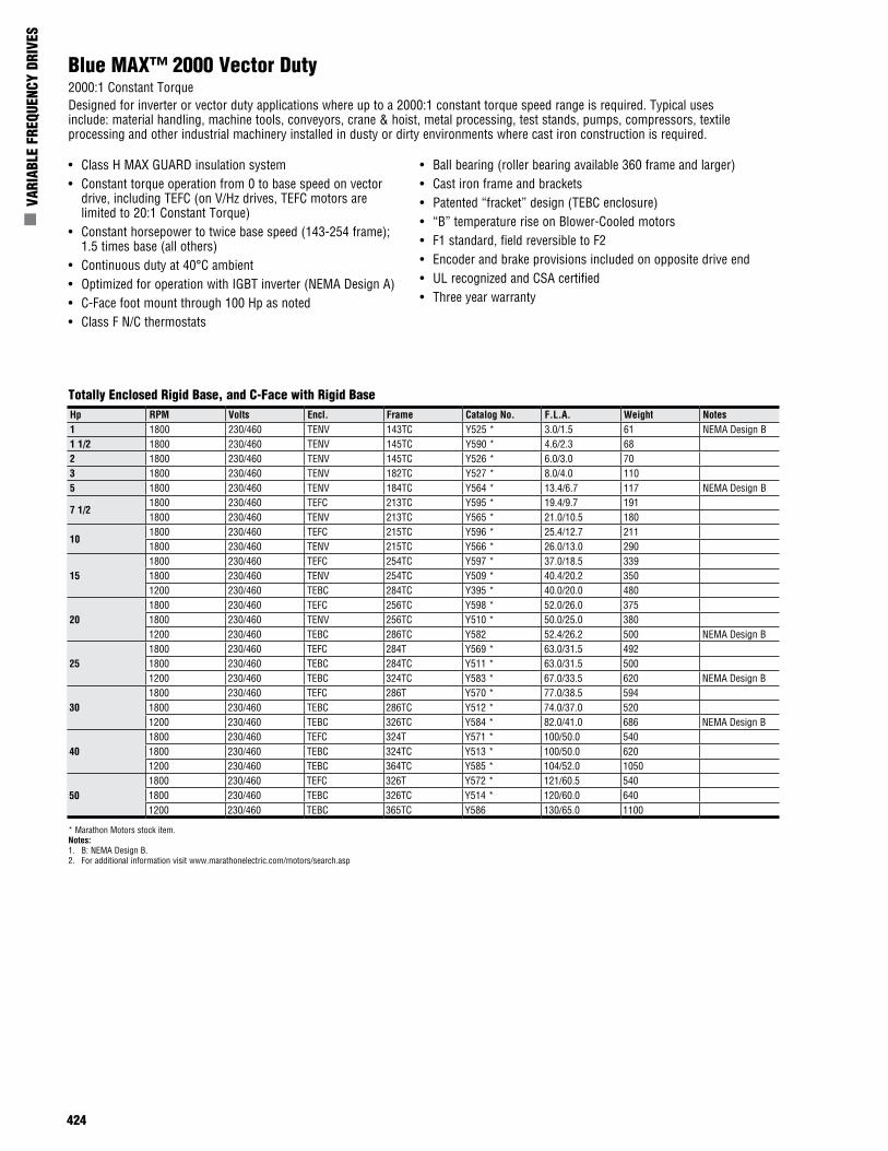
424
n V
ARIA
BLE
FREQ
UENC
Y DR
IVES
Blue MAX™ 2000 Vector Duty2000:1 Constant TorqueDesigned for inverter or vector duty applications where up to a 2000:1 constant torque speed range is required. Typical uses include: material handling, machine tools, conveyors, crane & hoist, metal processing, test stands, pumps, compressors, textile processing and other industrial machinery installed in dusty or dirty environments where cast iron construction is required.
• Class H MAX GUARD insulation system• Constant torque operation from 0 to base speed on vector
drive, including TEFC (on V/Hz drives, TEFC motors are limited to 20:1 Constant Torque)
• Constant horsepower to twice base speed (143-254 frame); 1.5 times base (all others)
• Continuous duty at 40°C ambient• Optimized for operation with IGBT inverter (NEMA Design A)• C-Face foot mount through 100 Hp as noted• Class F N/C thermostats
• Ball bearing (roller bearing available 360 frame and larger)• Cast iron frame and brackets• Patented “fracket” design (TEBC enclosure)• “B” temperature rise on Blower-Cooled motors• F1 standard, field reversible to F2• Encoder and brake provisions included on opposite drive end• UL recognized and CSA certified• Three year warranty
Totally Enclosed Rigid Base, and C-Face with Rigid BaseHp RPM Volts Encl. Frame Catalog No. F.L.A. Weight Notes1 1800 230/460 TENV 143TC Y525 * 3.0/1.5 61 NEMA Design B1 1/2 1800 230/460 TENV 145TC Y590 * 4.6/2.3 682 1800 230/460 TENV 145TC Y526 * 6.0/3.0 703 1800 230/460 TENV 182TC Y527 * 8.0/4.0 1105 1800 230/460 TENV 184TC Y564 * 13.4/6.7 117 NEMA Design B
7 1/21800 230/460 TEFC 213TC Y595 * 19.4/9.7 1911800 230/460 TENV 213TC Y565 * 21.0/10.5 180
101800 230/460 TEFC 215TC Y596 * 25.4/12.7 2111800 230/460 TENV 215TC Y566 * 26.0/13.0 290
151800 230/460 TEFC 254TC Y597 * 37.0/18.5 3391800 230/460 TENV 254TC Y509 * 40.4/20.2 3501200 230/460 TEBC 284TC Y395 * 40.0/20.0 480
201800 230/460 TEFC 256TC Y598 * 52.0/26.0 3751800 230/460 TENV 256TC Y510 * 50.0/25.0 3801200 230/460 TEBC 286TC Y582 52.4/26.2 500 NEMA Design B
251800 230/460 TEFC 284T Y569 * 63.0/31.5 4921800 230/460 TEBC 284TC Y511 * 63.0/31.5 5001200 230/460 TEBC 324TC Y583 * 67.0/33.5 620 NEMA Design B
301800 230/460 TEFC 286T Y570 * 77.0/38.5 5941800 230/460 TEBC 286TC Y512 * 74.0/37.0 5201200 230/460 TEBC 326TC Y584 * 82.0/41.0 686 NEMA Design B
401800 230/460 TEFC 324T Y571 * 100/50.0 5401800 230/460 TEBC 324TC Y513 * 100/50.0 6201200 230/460 TEBC 364TC Y585 * 104/52.0 1050
501800 230/460 TEFC 326T Y572 * 121/60.5 5401800 230/460 TEBC 326TC Y514 * 120/60.0 6401200 230/460 TEBC 365TC Y586 130/65.0 1100
* Marathon Motors stock item.Notes:1. B: NEMA Design B.2. For additional information visit www.marathonelectric.com/motors/search.asp
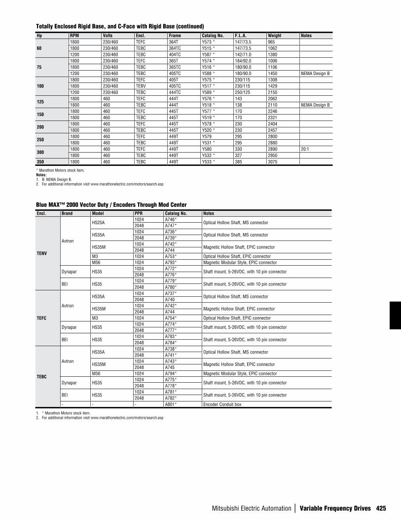
Mitsubishi Electric Automation | Variable Frequency Drives 425
Totally Enclosed Rigid Base, and C-Face with Rigid Base (continued)Hp RPM Volts Encl. Frame Catalog No. F.L.A. Weight Notes
601800 230/460 TEFC 364T Y573 * 147/73.5 9651800 230/460 TEBC 364TC Y515 * 147/73.5 10621200 230/460 TEBC 404TC Y587 * 142/71.0 1380
751800 230/460 TEFC 365T Y574 * 184/92.0 10061800 230/460 TEBC 365TC Y516 * 180/90.0 11061200 230/460 TEBC 405TC Y588 * 180/90.0 1450 NEMA Design B
1001800 230/460 TEFC 405T Y575 * 230/115 13081800 230/460 TEBV 405TC Y517 * 230/115 14291200 230/460 TEBC 444TC Y589 * 250/125 2150
1251800 460 TEFC 444T Y576 * 143 20621800 460 TEBC 444T Y518 * 138 2110 NEMA Design B
1501800 460 TEFC 445T Y577 * 170 22461800 460 TEBC 445T Y519 * 170 2321
2001800 460 TEFC 445T Y578 * 230 24041800 460 TEBC 445T Y520 * 230 2457
2501800 460 TEFC 449T Y579 295 28001800 460 TEBC 449T Y531 * 295 2880
3001800 460 TEFC 449T Y580 330 2890 20:11800 460 TEBC 449T Y532 * 327 2950
350 1800 460 TEBC 449T Y533 * 385 3075
* Marathon Motors stock item.Notes:1. B: NEMA Design B.2. For additional information visit www.marathonelectric.com/motors/search.asp
Encl. Brand Model PPR Catalog No. Notes
TENV
Avtron
HS25A1024 A746*
Optical Hollow Shaft, MS connector2048 A747*
HS35A1024 A736*
Optical Hollow Shaft, MS connector2048 A739*
HS35M1024 A742*
Magnetic Hollow Shaft, EPIC connector2048 A744
M3 1024 A753* Optical Hollow Shaft, EPIC connectorM56 1024 A793* Magnetic Modular Style, EPIC connector
Dynapar HS351024 A772*
Shaft mount, 5-26VDC, with 10 pin connector2048 A776*
BEI HS351024 A779*
Shaft mount, 5-26VDC, with 10 pin connector2048 A780*
TEFC
Avtron
HS35A1024 A737*
Optical Hollow Shaft, MS connector2048 A740
HS35M1024 A742*
Magnetic Hollow Shaft, EPIC connector2048 A744
M3 1024 A754* Optical Hollow Shaft, EPIC connector
Dynapar HS351024 A774*
Shaft mount, 5-26VDC, with 10 pin connector2048 A777*
BEI HS351024 A783*
Shaft mount, 5-26VDC, with 10 pin connector2048 A784*
TEBC
Avtron
HS35A1024 A738*
Optical Hollow Shaft, MS connector2048 A741*
HS35M1024 A743*
Magnetic Hollow Shaft, EPIC connector2048 A745
M56 1024 A794* Magnetic Modular Style, EPIC connector
Dynapar HS351024 A775*
Shaft mount, 5-26VDC, with 10 pin connector2048 A778*
BEI HS351024 A781*
Shaft mount, 5-26VDC, with 10 pin connector2048 A782*
- - - A801* Encoder Conduit box
1. * Marathon Motors stock item.2. For additional information visit www.marathonelectric.com/motors/search.asp
Blue MAX™ 2000 Vector Duty / Encoders Through Mod Center

426
n V
ARIA
BLE
FREQ
UENC
Y DR
IVES