variable input constant output 3-phase ac-dc
TRANSCRIPT
i
VARIABLE INPUT CONSTANT OUTPUT 3-PHASE AC-DC CONVERTER
MOHD IZZUDDIN BIN ABD KADIR
This thesis is submitted as partial fulfillment of the
requirements for the award of the
Bachelor Degree of Electrical Engineering (Power Systems)
Faculty of Electrical & Electronics Engineering
Universiti Malaysia Pahang
NOVEMBER 2010

ii
“All the trademark and copyrights use herein are property of their respective owner.
References of information from other sources are quoted accordingly; otherwise the
information presented in this report is solely work of the author.”
Signature : ____________________________
Author :MOHD IZZUDDIN BIN ABD KADIR
Date :29 NOVEMBER 2010

iv
ACKNOWLEDGEMENT
First at all, I would like to thank God the Almighty for his bless towards myself.
Without his blessing I might not able to complete my final year project entitle “ variable
input-constant output, three phase ac-dc converter”.
I would also like to take this opportunity to thank all the people who had assisted
me directly and indirectly in completing the project. My first gratitude goes to Mr.
Ramdan bin Razali, my supervisor for the project whom had given support, advice and
guidance I might need. He had been guiding me from the start of the project until the
final touch of the thesis write up. With his helps, I had learned many things regarding
the project, as well as extra knowledge that I believe I would not have this sort of
opportunity elsewhere. The project would obviously not be successful without him. A
million thanks to Mr. Ramdan bin Razali.
Very special thanks also to other friends who had guided and helped me a lot
with the project. Not to forget, I would also wish to thank all of my lecturers who had
given their full co-operation. They had never hesitated to share knowledge and opinions
in ensuring the project be completed successfully.
Last but not least, I would like to thank my beloved parents who had given me a
lot of moral support while I was struggling with this project.
Once again to all, thank you very much.
v
ABSTRACT
Generator which powered by motorcycle engine will produce variable ac voltage
because the engine running with difference RPM . If uncontrolled ac-dc converter is
used, the output will be unhealthy variable DC voltage and not suitable for charging the
battery. This project will use controlled ac-dc converter which will produce considerably
constant output dc voltage at variable ac input. The converter uses controllable power
switches to produce dc voltage output at 13-15 volt which is then can be use to charge
the battery. The benefit of this project is it will be able to control the input from the
three- phase generators vehicles specially motorcycle without any problem.

vi
ABSTRAK
Penghasil kuasa yang menghasilkan kuasa dari engin motosikal akan
menghasilkan pelbagai arus ulang alik kerana engin beroperasi dengan revolusi setiap
minit (RPM ) yang pelbagai. Jika penukar arus ulang alik kepada arus terus yang tidak
dikawal digunakan, keluaran akan menghasilkan voltage arus terus yang tidak sesuai
untuk digunakan sebagai pengecas bateri. Projek ini akan menggunakan penukar arus
ulang alik kepada arus terus yang dikawal dimana akan menghasilkan arus terus yang
tetap pada pelbagai masukan arus ulang alik. Penukar arus ini menggunakan suis kuasa
untuk menghasilkan keluaran diantara 13 hingga 15 volt dimana ia akan digunakan
untuk mengecas batteri. Faedah projek ini ialah ia akan mampu mengawal arus masukan
daripada 3 fasa penghasil kuasa contohnya motosikal tanpa sebarang masalah.

vii
TABLE OF CONTENTS
CHAPTER TITLE PAGE
DECLARATION OF THESIS’S STATUS ii
DEDICATION iii
DECLARATION OF SUPERVISOR iv
ACKNOWLEDGEMENT v
ABSTRACT vi
ASTRAK vii
LIST OF FIGURES x
LIST OF ABBREVIATIONS xi
LIST OF APPENDICS xii
LIST OF TABLE xii
1 INTRODUCTION 1
1.1 Overview 1
1.2 Background 3
1.3 Objectives 5
1.4 Scopes 4
1.5 Problem Statement 5
1.6 Thesis outline 6

viii
2 LITERATURE REVIEW 8
2.1 Introduction 8
2.2 Synchronous Rectifier 9
2.3 Hybrid Rectifier 11
2.4 PWM Rectifiers 14
2.5 Selenium Rectifier 16
3 METHODOLOGY 17
3.1 Introduction 17
3.2 Control Unit 19
3.3 Capacitor Filter 21
3.4 Battery Charger 23
3.5 +5v Power Supply 25
3.6 Transformer 27
4 RESULT & ANALYSIS 28
4.1 Introduction 28
4.2 Mathematical Analysis 28
4.21 Calculation Of Three Phase Rectifier 29
4.2.2 Time Delay Calculation 30
4.3 Hardware Development 34
5 CONCLUSION AND RECOMMENDATION 37
5.1 Conclusion 37
5.2 Recommendation 38
5.3 Costing And Commercialization 38
5.3.1 Costing 38
5.3.2 Commercialization 40
ix
REFERENCES 41
APPENDIX A 43 46
APPENDIX B 47-73
APPENDIX C 74
LIST OF FIGURES
FIGURE NO. TITLE PAGE
1.1 Four type of Conversion 2
1.2 Power Processor & Controller 4
2.1 Synchronous rectifier 8
2.2 Simplified schematic of a vehicle’s electrical power supply 9
2.3 Output characteristic of a passenger vehicle 10
2.4 Trolleybuses 11
2.5 Single-phase diode-rectifier 13
2.6 Configuration of the two rectifier systems 14
2.7 Main circuit of a PWM rectifier unit 15
3.1 Flow chart of the methodology 18
3.2 Block diagram for the hardware part 19
3.3 Interfacing PIC with SCR 20
3.3 Capacitor filter 21
3.6 Charging circuit 22
3.7 Output of charging circuit 24
3.8 Voltage regulator, LM 7805 25
3.9 Schematic Circuit Of +5v Power Supply 25
3.10 Simulation Of Regulated +5 Volt Source Using Proteus Software26
3.11 Graf of of regulated +5v dc output. 26
x
3.12 Transformer 27
4.1 Voltage output waveform for one cycle period at difference 33
firing angle
4.2 Hardware Connection 240VAC transformer 34
4.3 Hardware of project 35
LIST OF ABBREVIATIONS
AC - Alternate Current
DC - Direct Current
SCR - Silicon Control Rectifier
PIC - Programmable Interface Controller
GTO - Gate Turn-Off Thyristor
VCD - Variable speed drive
THDI - Total Harmonic Distortion Current
MOSFET - Metal–Oxide–Semiconductor Field-Effect Transistor
HPF - High Power Factor
PWM - Pulse-Width Modulation
IC - Integrated Circuit
xi
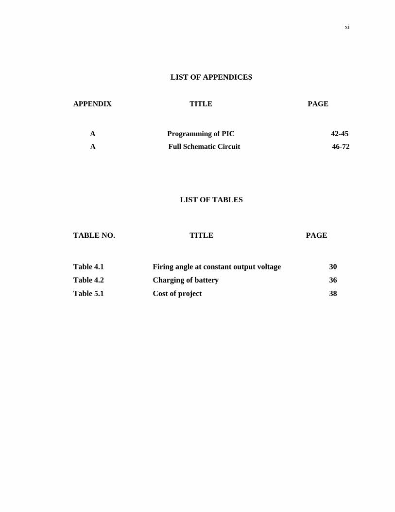
LIST OF APPENDICES
APPENDIX TITLE PAGE
A Programming of PIC 42-45
A Full Schematic Circuit 46-72
LIST OF TABLES
TABLE NO. TITLE PAGE
Table 4.1 Firing angle at constant output voltage 30
Table 4.2 Charging of battery 36
Table 5.1 Cost of project 38
1
CHAPTER 1
INTRODUCTION
1.1 Overview
The modern era of power electronics began in 1958 ,when the General Electric
Company introduced a commercial thyristor ,two years after it was invented by Bell
Telephone Laboratory. Soon all industrial applications that were based on mercury arc
rectifiers and power magnetic amplifiers were replaced by silicon-controlled
rectifiers(SCRs).In less than 20 years after commercial SCRs were introduced
significant improvements in semiconductor fabrication technology and physical
operation were made ,and many different types of power semiconductor devices
appeared. The growth in power electronics was made possible with the
microelectronic revolution of the 1970s and 1980s, in which the low power IC control
chips provided the brain and the intelligence to control the high – power
semiconductor devices .Moreover the introduction of microprocessors made it
possible to apply modern control theory to power electronics. In the last 20 years ,the
growth in power electronics application has been remarkable because of this
introduction of very fast and high-power switching devices, coupled with the
utilization of state-of –the –art control algorithms. An electric power can be converted
from one form to another form by using power electronics devices. The function of
power electronics circuits by using semiconductor devices as switch is modifying or
controlling a voltage. The goal of power electronics circuits are to convert electrical
energy from one form to another, from source to load with highest efficiency, high
availability and high reliability with the lowest cost, smallest size and weight.
2
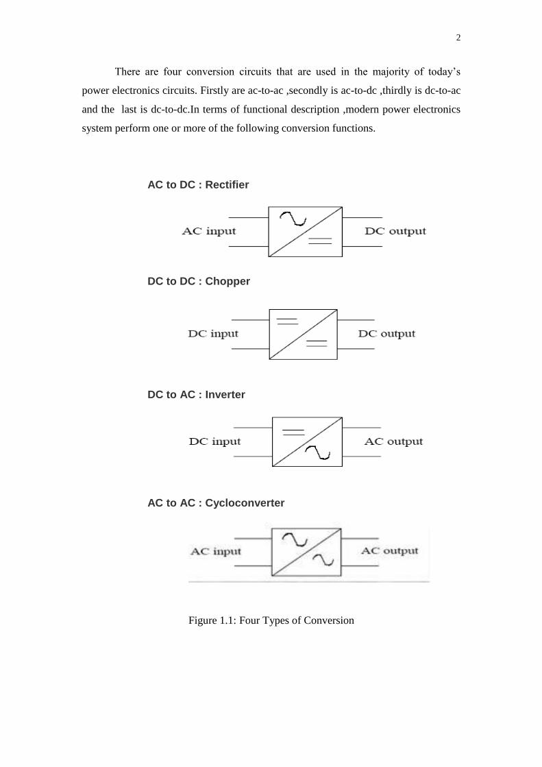
There are four conversion circuits that are used in the majority of today’s
power electronics circuits. Firstly are ac-to-ac ,secondly is ac-to-dc ,thirdly is dc-to-ac
and the last is dc-to-dc.In terms of functional description ,modern power electronics
system perform one or more of the following conversion functions.
AC to DC : Rectifier
DC to DC : Chopper
DC to AC : Inverter
AC to AC : Cycloconverter
Figure 1.1: Four Types of Conversion
3
1.2 Background
Power electronic converters can be found wherever there is a need to modify a
form of electrical energy (i.e. change its voltage, current or frequency). The power
range of these converters is from some milliwatts (as in a mobile phone) to hundreds
of megawatts (e.g. in a HVDC transmission system). With classical electronics,
electrical currents and voltage are used to carry information, whereas with power
electronics, they carry power. Thus, the main metric of power electronics becomes the
efficiency.
The first very high power electronic devices were mercury arc valves. In
modern systems the conversion is performed with semiconductor switching devices
such as diodes, thyristors and transistors. In contrast to electronic systems concerned
with transmission and processing of signals and data, in power electronics substantial
amounts of electrical energy are processed. An AC/DC converter (rectifier) is the
most typical power electronics device found in many consumer electronic devices,
e.g. television sets, personal computers, battery chargers, etc. The power range is
typically from tens of watts to several hundred watts. In industry the most common
application is the variable speed drive (VSD) that is used to control an induction
motor. The power range of VSDs start from a few hundred watts and end at tens of
megawatts.
Power electronics refers to control and conversion of electrical power by
power semiconductor devices wherein these devices operate as switches. Advent of
silicon-controlled rectifiers, abbreviated as SCRs, led to the development of a new
area of application called the power electronics. Prior to the introduction of SCRs,
mercury-arc rectifiers were used for controlling electrical power, but such rectifier
circuits were part of industrial electronics and the scope for applications of mercury-
arc rectifiers was limited. Once the SCRs were available, the application area spread
to many fields such as drives, power supplies, aviation electronics, high frequency
inverters and power electronics originated.
4
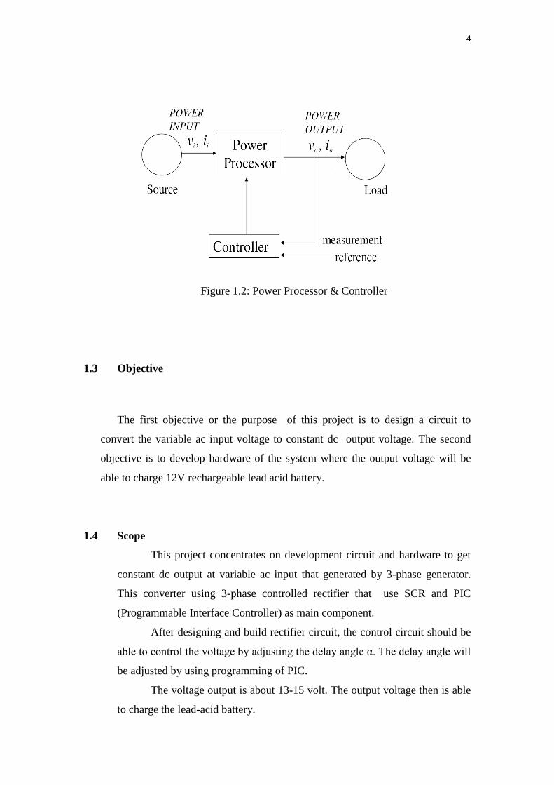
Figure 1.2: Power Processor & Controller
1.3 Objective
The first objective or the purpose of this project is to design a circuit to
convert the variable ac input voltage to constant dc output voltage. The second
objective is to develop hardware of the system where the output voltage will be
able to charge 12V rechargeable lead acid battery.
1.4 Scope
This project concentrates on development circuit and hardware to get
constant dc output at variable ac input that generated by 3-phase generator.
This converter using 3-phase controlled rectifier that use SCR and PIC
(Programmable Interface Controller) as main component.
After designing and build rectifier circuit, the control circuit should be
able to control the voltage by adjusting the delay angle α. The delay angle will
be adjusted by using programming of PIC.
The voltage output is about 13-15 volt. The output voltage then is able
to charge the lead-acid battery.
5
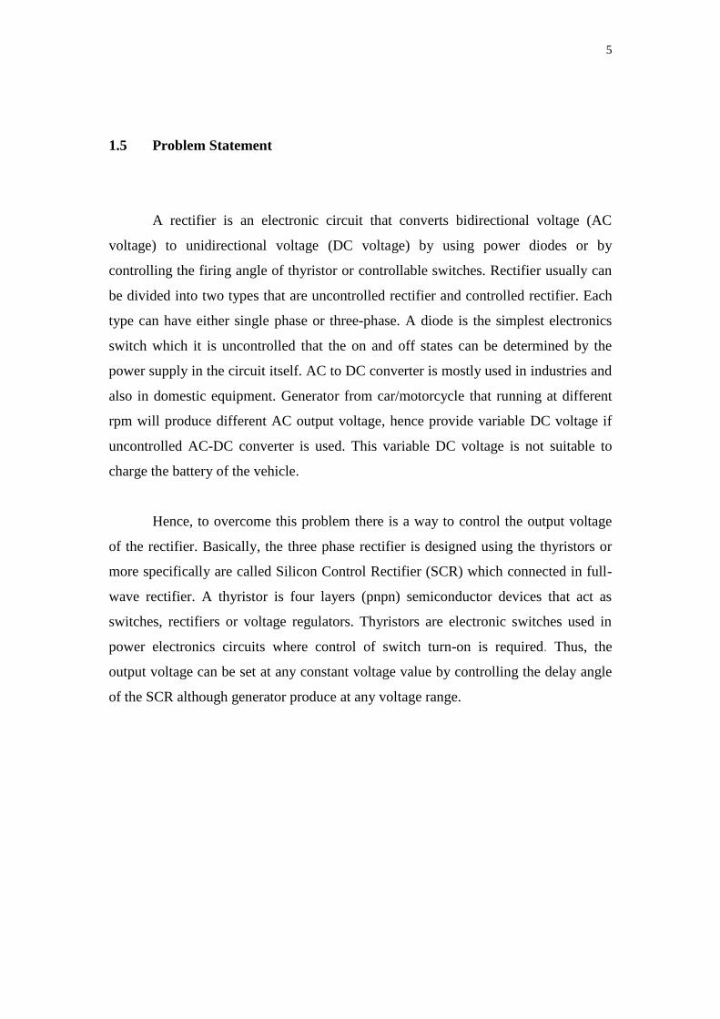
1.5 Problem Statement
A rectifier is an electronic circuit that converts bidirectional voltage (AC
voltage) to unidirectional voltage (DC voltage) by using power diodes or by
controlling the firing angle of thyristor or controllable switches. Rectifier usually can
be divided into two types that are uncontrolled rectifier and controlled rectifier. Each
type can have either single phase or three-phase. A diode is the simplest electronics
switch which it is uncontrolled that the on and off states can be determined by the
power supply in the circuit itself. AC to DC converter is mostly used in industries and
also in domestic equipment. Generator from car/motorcycle that running at different
rpm will produce different AC output voltage, hence provide variable DC voltage if
uncontrolled AC-DC converter is used. This variable DC voltage is not suitable to
charge the battery of the vehicle.
Hence, to overcome this problem there is a way to control the output voltage
of the rectifier. Basically, the three phase rectifier is designed using the thyristors or
more specifically are called Silicon Control Rectifier (SCR) which connected in full-
wave rectifier. A thyristor is four layers (pnpn) semiconductor devices that act as
switches, rectifiers or voltage regulators. Thyristors are electronic switches used in
power electronics circuits where control of switch turn-on is required. Thus, the
output voltage can be set at any constant voltage value by controlling the delay angle
of the SCR although generator produce at any voltage range.
6
1.6 Thesis Outline
There are all five chapters being structures in this thesis and every chapter will
elaborate in detail about this project. For the first chapter, an overview about this
project, variable input constant output 3 phase ac-dc converter is discussed including
the objectives and scopes of the project as a guide to develop three phase controlled
rectifier.
Chapter 2 will explain and discuss on the literature review of the three phase
controlled rectifier. The literature review is taken from jurnal/proceeding with related
to the project.
Chapter 3 discusses the methodologies of the three phase controlled rectifier
that has been applied in completing this project. In this chapter, it consists of block
diagram and flow chart which are explained about the process of implementation and
how the three phase AC voltage converts to DC voltage then connected to the battery
as a load. It is also discusses briefly how the output voltage can be varied.
Chapter 4 is discussing and displaying all the results obtained and the
limitation of the project. All discussions are concentrated on the result and the overall
performance of the three phase controlled rectifier.
Chapter 5 in overall will discuss on the conclusion and summary of the
development of the three phase controlled rectifier project. In this chapter also
discusses on the recommendation for this project development or modification.
CHAPTER II
LITERATURE REVIEW
2.1 Introduction
This chapter presents an overview of rectifier. A rectifier is an electrical device that
converts alternating current (AC), which periodically reverses direction, to direct current (DC).
Rectifiers have many uses including as components of power supplies and
as detectors of radio signals. Rectifiers may be made of solid state diodes, vacuum
tube diodes, mercury arc valves, and other components.
The rectifier also use for vehicle. There are some uses of rectifier in vehicle such as for
electric vehicle, trolleybus systems, mechanical batteries and others. Hence, this project
proposed for the control of output voltage for vehicle such as motorcycle to produce constant
voltage from its alternator. There are many type of rectifier that can be use for the vehicle.
2.2 Synchronous Rectifier
The synchronous rectification is a technique for improving efficiency of power
converters in power electronics. It consists of connecting a diode and a transistor (usually
a power MOSFET) in parallel. When the diode is forward-biased, the transistor is turned on, to
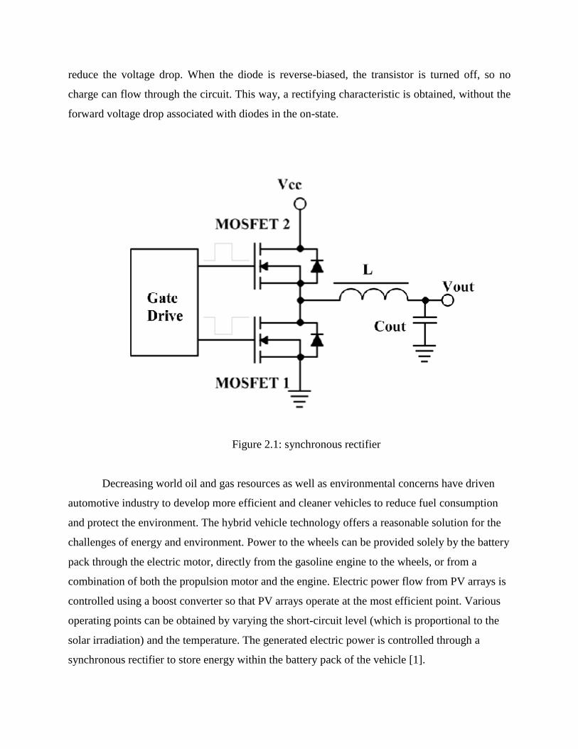
reduce the voltage drop. When the diode is reverse-biased, the transistor is turned off, so no
charge can flow through the circuit. This way, a rectifying characteristic is obtained, without the
forward voltage drop associated with diodes in the on-state.
Figure 2.1: synchronous rectifier
Decreasing world oil and gas resources as well as environmental concerns have driven
automotive industry to develop more efficient and cleaner vehicles to reduce fuel consumption
and protect the environment. The hybrid vehicle technology offers a reasonable solution for the
challenges of energy and environment. Power to the wheels can be provided solely by the battery
pack through the electric motor, directly from the gasoline engine to the wheels, or from a
combination of both the propulsion motor and the engine. Electric power flow from PV arrays is
controlled using a boost converter so that PV arrays operate at the most efficient point. Various
operating points can be obtained by varying the short-circuit level (which is proportional to the
solar irradiation) and the temperature. The generated electric power is controlled through a
synchronous rectifier to store energy within the battery pack of the vehicle [1].
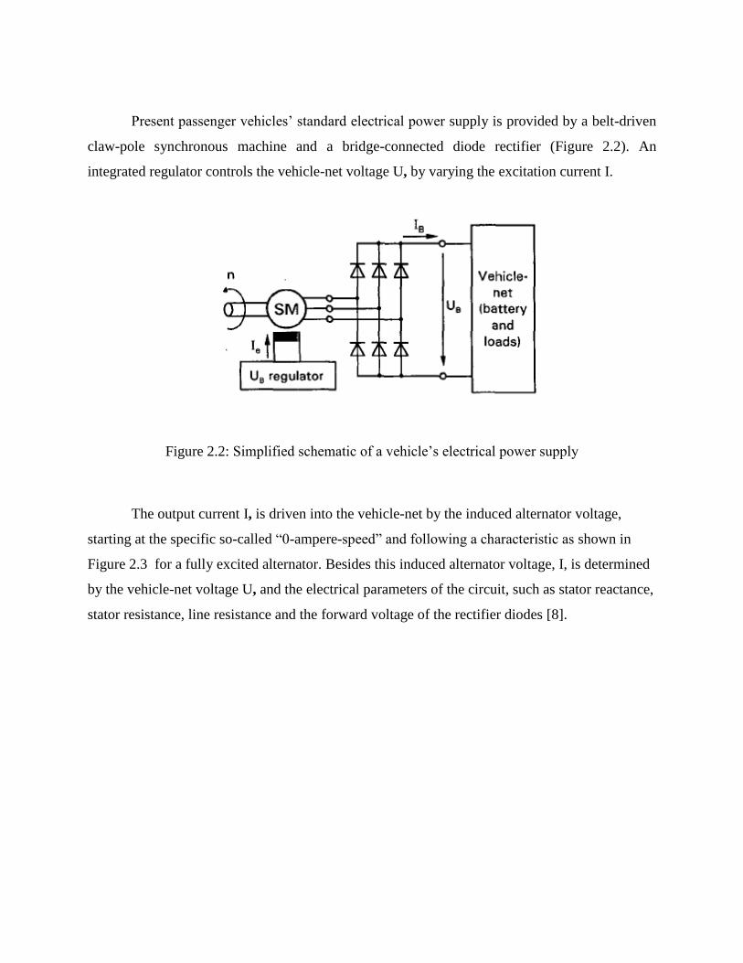
Present passenger vehicles’ standard electrical power supply is provided by a belt-driven
claw-pole synchronous machine and a bridge-connected diode rectifier (Figure 2.2). An
integrated regulator controls the vehicle-net voltage U, by varying the excitation current I.
Figure 2.2: Simplified schematic of a vehicle’s electrical power supply
The output current I, is driven into the vehicle-net by the induced alternator voltage,
starting at the specific so-called “0-ampere-speed” and following a characteristic as shown in
Figure 2.3 for a fully excited alternator. Besides this induced alternator voltage, I, is determined
by the vehicle-net voltage U, and the electrical parameters of the circuit, such as stator reactance,
stator resistance, line resistance and the forward voltage of the rectifier diodes [8].
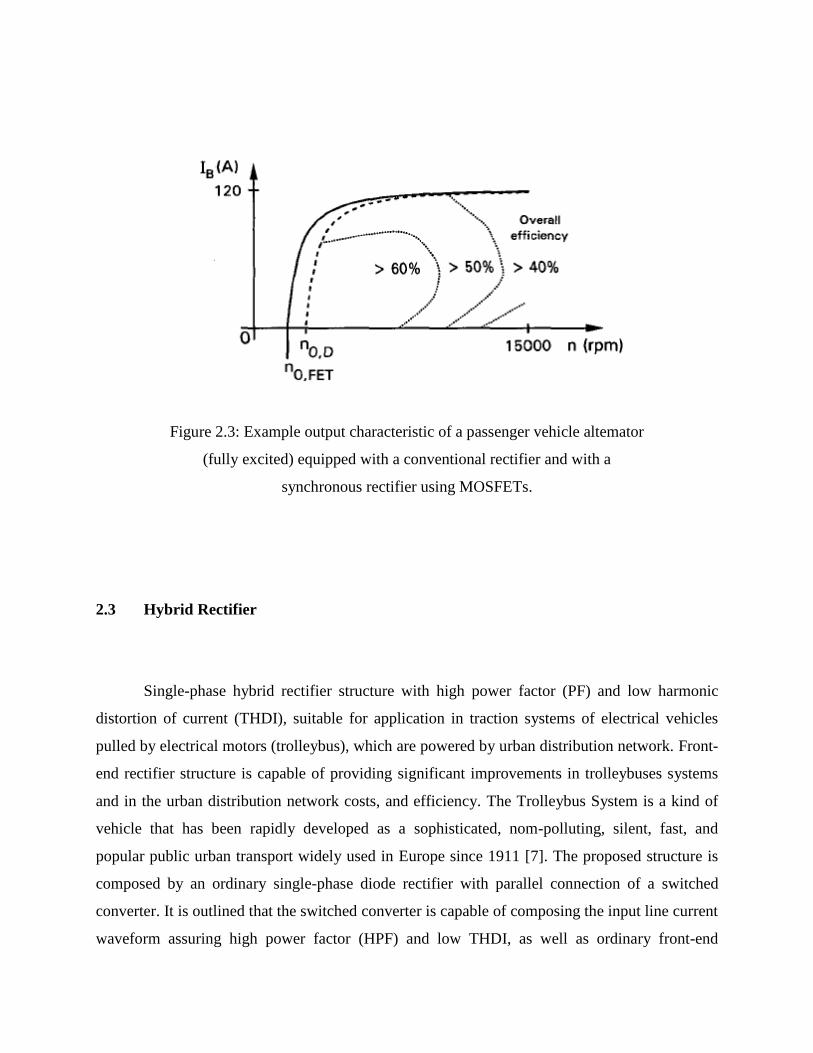
Figure 2.3: Example output characteristic of a passenger vehicle altemator
(fully excited) equipped with a conventional rectifier and with a
synchronous rectifier using MOSFETs.
2.3 Hybrid Rectifier
Single-phase hybrid rectifier structure with high power factor (PF) and low harmonic
distortion of current (THDI), suitable for application in traction systems of electrical vehicles
pulled by electrical motors (trolleybus), which are powered by urban distribution network. Front-
end rectifier structure is capable of providing significant improvements in trolleybuses systems
and in the urban distribution network costs, and efficiency. The Trolleybus System is a kind of
vehicle that has been rapidly developed as a sophisticated, nom-polluting, silent, fast, and
popular public urban transport widely used in Europe since 1911 [7]. The proposed structure is
composed by an ordinary single-phase diode rectifier with parallel connection of a switched
converter. It is outlined that the switched converter is capable of composing the input line current
waveform assuring high power factor (HPF) and low THDI, as well as ordinary front-end
converter. Concerning the development of power electronic converters for trolleybus system
applications, one of the great challenges faced by researchers is to develop electronic traction
control systems with reduced weight and size, once that these converters, usually connected to a
DC distribution network, must be able to deal with high power levels, around 150kW.
This converter must also be able to supply the demanded high power assuring high power
factor and low current harmonic distortion when in AC, due to many disadvantages of the
presence of harmonic current components in the AC distribution network , maintaining the same
performance when in DC. Therefore, the power electronic converters used in trolleybuses, when
supplied by single-phase AC distribution networks require a front-end rectifier in order to
provide an intermediate DC link for connection of DC or AC adjustable speed drivers.
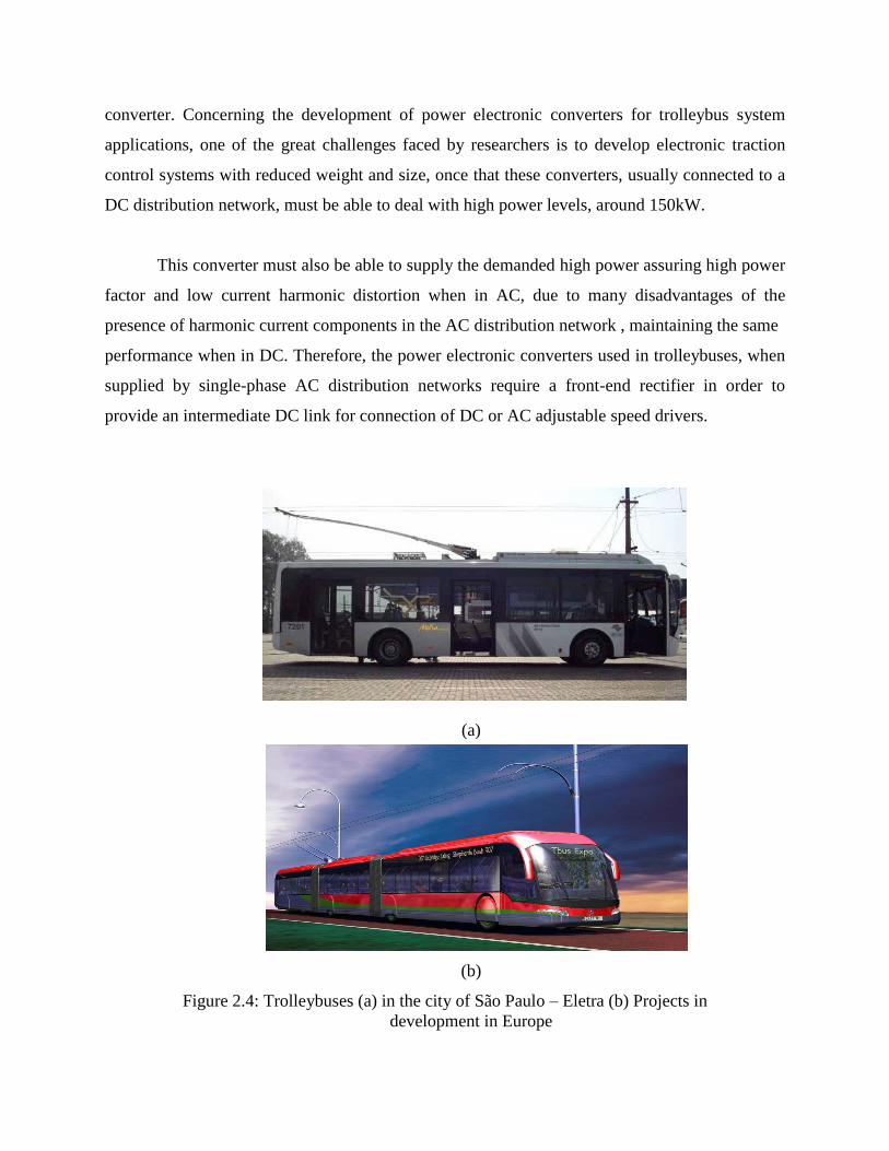
(a)
(b)
Figure 2.4: Trolleybuses (a) in the city of São Paulo – Eletra (b) Projects in
development in Europe
When operating in AC, those front-end converters represent a medium to high power
single-phase non linear loads, and if concentrated only in one phase of the three-phase power
system, it will cause unbalances and many disadvantages related to the presence of harmonic
current components in the AC distribution network due to its operation characteristics. In this
way, a Scott transformer is a kind of equipment widely used in order to convert the three-phase
power supply into two single-phase power supplies, distributing the load between the primary
windings of the transformer and, therefore, mitigating the unbalance problems.
However, the input line current waveform of conventional diode-rectifier circuits
presents itself as a non-sinusoidal waveform, thus, the implementation of robustness and reliable
front-end converters capable of operating in accordance with harmonic content restrictions
imposed by international standards such as IEC 61000-3-4, becomes a mandatory issue [2].
The major advantage provided by hybrid rectifiers, three-phase or single-phase, is the
association of the robustness, simplicity, and reliability of diode-rectifiers with the reduction of
volume, weight, and size provided by high frequency switched converters. Thus, the rated power
can be drastically increased without compromising the global structure efficiency. The main
advantages achieved when hybrid rectifiers are used in order to provide intermediate DC link for
power electronic converters connection are:
• Higher global efficiency once that the switched converter must be rated at a fraction of the
nominal power.
• Reduced weight and size when compared to ordinary single-phase HPF front-end rectifiers.
• Flexibility in attention to IEC61000-3-4 limits, since the input line current waveform can
assume different wave shapes, depending on the desired THDI.
• Simple, efficient, and low cost control technique.
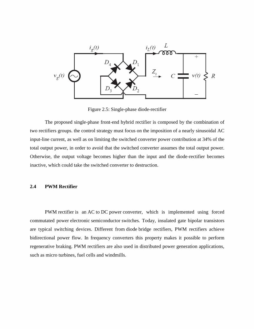
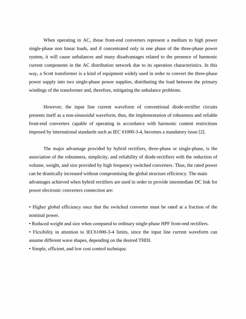
Figure 2.5: Single-phase diode-rectifier
The proposed single-phase front-end hybrid rectifier is composed by the combination of
two rectifiers groups. the control strategy must focus on the imposition of a nearly sinusoidal AC
input-line current, as well as on limiting the switched converter power contribution at 34% of the
total output power, in order to avoid that the switched converter assumes the total output power.
Otherwise, the output voltage becomes higher than the input and the diode-rectifier becomes
inactive, which could take the switched converter to destruction.
2.4 PWM Rectifier
PWM rectifier is an AC to DC power converter, which is implemented using forced
commutated power electronic semiconductor switches. Today, insulated gate bipolar transistors
are typical switching devices. Different from diode bridge rectifiers, PWM rectifiers achieve
bidirectional power flow. In frequency converters this property makes it possible to perform
regenerative braking. PWM rectifiers are also used in distributed power generation applications,
such as micro turbines, fuel cells and windmills.
The dc power supply in traction power conversion system is provided by uncontrolled
diode and phase-controlled thyristor rectifier in feeding system of high-speed maglev vehicles,
Shanghai.
Figure 2.6: Configuration of the two rectifier systems
Due to the distinct advantages of PWM rectifier, substituting multi-module PWM
rectifier for uncontrolled diode and phase-controlled thyristor rectifier can obtain a optimal
system configuration. In multi-module PWM rectifier system, only small high-frequency
harmonic filters are required. The braking energy can flow back to utility through PWM rectifier.
At the same time, PWM rectifier has the ability to improve the dynamic performance of whole
system with fast response.
The three-phase PWM rectifier offers distinct advantages compared to conventional
uncontrolled diode or phase-controlled thyristor rectifier. The advantages include nearly
sinusoidal input currents, controllable input power factor, high quality dc output voltage, and
bidirectional power flow. With proper control approach, the multi-module PWM rectifier can
achieve harmonic reduction while maintaining low switching frequency. PWM rectifier has the
ability to improve the dynamic performance of whole system with fast response [3].