variable speed supercharger drive
TRANSCRIPT

Variable Speed Supercharger Drive
Final Report
Team 31: Melissa Jarman, Kyle McMahon, Michael Ng, Tim Slusser 4/15/2008
2
Executive Summary. With the installation of a continuously variable transmission (CVT) between the driving belt and the supercharger, the pulley ratio can be changed on demand. The introduction of this variable transmission will remove the need for a boost pressure bypass valve and increase the efficiency of the supercharger system during all loading conditions. The variable diameter pulley system necessary for this CVT has been designed, but there currently are no means of which to actuate the scroll plate that changes pulley diameter. The scope of this project is to design the system or device that will actuate the scroll plate allowing for this CVT system to function. One major issue that must be overcome is that the scroll plate will need to be actuated while rotating. Several design specifications have already been established. These design specifications were formulated based on technical criteria that must be met in order for the system to be successful. The technical criteria that were provided are as follows:
• Supercharger speed will vary from 800 rpm to 5000rpm • Scroll plate must rotate six complete revolutions relative to supercharger drive • Full actuation (six revolutions) time must take less than two seconds • Maximum torque required to rotated the scroll plate relative to the supercharger drive is
10 Nm • Actuator must contain a locking mechanism to hold scroll plate position • Actuator can be powered by any feasible means
The major engineering problems associated with this system include: being restricted to building off the current system components, actuating a rotating object and converting of energy to power this actuation. In addition, it will be necessary to take supercharger speed into account when calculating actuation time. As these engineering needs are addressed it is important to ensure that all rotational systems are balanced, including any components that may be added to the system. The concept generation process was completed by using a functional decomposition, morphological chart, and finally a Pugh chart to compare the top five design choices. The alpha design is the packaged gear ratios concept. This design uses a set of gear ratios to alter the speed of the scroll plate which in turn changes the radius of the pulley. The packaged gear ratio was chosen as the best design because it accomplishes all functions set by the engineering design requirements in a simple and efficient way. Our chosen alpha design was established and then scrutinized during engineering analysis until a final design was chosen. Ideal and final designs have been developed. Both designs include a 1:1 gear ratio to accomplish pulley-locking needs and gear ratios that will increase and decrease the pulley diameter in less than two seconds. The ideal design however utilizes electromagnetic clutches that do not currently exist. The final design uses sets of step-down gears, therefore allowing the shaft speed to be reduced to current specs of clutches. Physical and virtual prototypes were completed to show our final design. The physical prototype is a very simple means of demonstrating the main engineering ideas of the system while the virtual prototype handles the specifics of the actual final design.

3
Table of Contents 1. Introduction. ................................................................................................................................ 4
1.1 Project and Sponsor .............................................................................................................. 4 1.2. Problem Statement. .............................................................................................................. 5
2. Specifications .............................................................................................................................. 5 2.1. Information Sources. ............................................................................................................ 5 2.2. Customer Requirements and Engineering Specifications. ................................................... 6
3. Concept Generation .................................................................................................................... 7 3.1 Pulley System (Design 1)...................................................................................................... 9 3.2 Hydraulic Drill Design (Design 2) ...................................................................................... 10 3.3 Permanent Manipulator Gear (Design 3) ............................................................................ 11 3.4 V-belt System (Design 4).................................................................................................... 12 3.5 Packaged Gear Ratios (Design 5) ....................................................................................... 13
4. Concept Selection. .................................................................................................................... 13 5. Overall Concept Description ..................................................................................................... 14
5.1 Parameter Analysis ............................................................................................................. 14 5.2.1 Alpha Design Description ................................................................................................ 16 5.2.2 Final Design Description ................................................................................................. 19 5.3 Prototype Description ......................................................................................................... 21 5.4 Fabrication Plan .................................................................................................................. 21 5.5 Validation ............................................................................................................................ 22
6. Discussion ................................................................................................................................. 24 7. Recommendations ..................................................................................................................... 25 8. Summary. .................................................................................................................................. 26 9. References. ................................................................................................................................ 27 10. Appendix ................................................................................................................................. 28
Appendix A: Sketches ............................................................................................................... 28 Appendix B: Gear Calculations ................................................................................................ 37 Appendix C: Engineering Drawings-Ideal Model .................................................................... 38 Appendix D: Engineering Drawings- Final Design .................................................................. 45 Appendix E: Bill of Materials .................................................... Error! Bookmark not defined. Appendix F: Design Analysis Assignment from Lecture ......................................................... 68

4
1. Introduction.
1.1 Project and Sponsor The Environmental Protection Agency (EPA) is working on a test program to substantially reduce emissions from diesel engines. A key component of this program is adequate intake manifold pressure provided by a supercharger. To provide this boost efficiently, it is desirable to install a continuously variable transmission (CVT) between the driving belt and the supercharger to alter the pulley ratio on demand. A variable diameter pulley mechanism (figure 1), based on a scroll plate (similar to a lathe chuck mechanism, figure 2 and 3), has been completed. However, this CVT mechanism needs to be actuated: the scroll plate must be rotated relative to the supercharger pulley while the complete mechanism is spinning. An actuator mechanism will be built to deliver power to the spinning scroll plate and alter the drive ratio and supercharger speed on demand. This may be done mechanically, electrically, or with hydraulics.
Figure 1: Supercharger Pulley
Figure 2: Scroll plate- gear side

5
Figure 3: Scroll plate- Spiral side
1.2. Problem Statement. This project is sponsored by the Environmental Protection Agency (EPA) Clean Diesel engine project. Currently superchargers are fixed displacement air pumps that are belt driven by the engine. To bleed off excess air pressure, a bypass valve is used which leads to wasted energy. To correct this problem it is desired to be able to vary the speed of the supercharger which in turn will vary the air flow. In doing this, the energy wasted due to excess boost pressure can be eliminated. The major problem with this design is rotating and locking an already rotating device. 2. Specifications
2.1. Information Sources. To the best of our knowledge, no previous work has been completed that directly relates to this problem. This problem is unique from current technologies in that this engine uses a serpentine belt drive system. Currently there exists a CVT which uses a V-belt, however, this process cannot be adapted for the serpentine belt. The V-belt system was researched for greater understanding of how CVT systems work. A V-belt system is shown below in Figure 4.
Figure 4: V-belt System [1]

6
Other CVT systems were examined to see if how they differ from the setup we were trying to design. An investigation of current technologies that are being used in serpentine belt applications was conducted to identify key components for concept generation. We attempted to utilize the components of each separate system together to see if a new design could be created. One such component that we found in current systems was the magnetic clutch pulley, Figure 2. It uses electrical current to induce a magnetic field that can engage or disengage the pulley to or from its system.
Figure 5: Magnetic Clutch [2]
Gear actuating systems are commonly used on aircraft controls. The actuator systems (patent 4848663) used in this application is different from the alpha design because it uses a hydraulic motor to run the gear system [3]. The alpha design does not use hydraulics due to space limitations and the desire to use the input energy from the engine.
2.2. Customer Requirements and Engineering Specifications. The goal of the project is to design an actuator mechanism which will control the scroll plate position on the rotating supercharger drive. The customer provided the following detailed requirements for this project:
• Supercharger speed will vary from 800 rpm to 5000 rpm • Scroll plate must rotate six complete revolutions relative to supercharger drive • Full actuation (six revolutions) time less than two seconds • Maximum torque required to rotate scroll plate is 10 Nm • Actuator must increase/decrease supercharger pulley radius and lock in place • Actuator can be powered by any feasible means
All customer specifications were given as technical specifications. The actuation time specification was stated by the customer only as a suggestion, the rest of the specifications are required. An interaction between the actuation time requirement and the supercharger speed is found as the supercharger speed varies.

7
3. Concept Generation The problem was broken down into the different functions that were necessary for the designed mechanisms to complete. It was determined that there would be two main functions that the actuator mechanism must accomplish: rotate the scroll plate and lock the scroll plate position relative to the supercharger pulley. There are five inputs for the system, which includes two types of energy and three signals. We are assuming that the desired diameter, actual diameter and RPM of the supercharger shaft will be passed in as signals from an external controller which is outside the scope of our project. This external controller will have to be designed to calculate the actual diameter of the system based on a relationship between the pressure and mass flow rate of the supercharger and the diameter of the supercharger pulley. A simple comparator would then be able to determine the actuation time of the system based on the inputs of desired diameter, actual diameter and RPM of the system. The following is the functional decomposition of the problem (Figure 6).
Figure 6: Functional Decomposition The functional decomposition identified the functions that our design must accomplish. We then sought to find mechanisms to satisfy each function that was identified and included this in a morphological chart, Table 1 (pg.8).

8
Energy (locking) Mechanical Electrical Hydraulic Pneumatic
Energy (movement) Mechanical Electrical Hydraulic Pneumatic
Convert energy to motion Mechanical
Deliver motion to scroll plate Gear Lever arm Pulley Wire
Rotate scroll plate Gear
On/off switch Switch
Locking mechanism Clamp Electromagnet Stopper
Scroll plate position sensor Speed Position Table 1: Morphological Chart
Design Number
Energy (locking)
Energy (movement)
Convert energy to motion
Deliver motion to scroll plate
Rotate scroll plate
On/off switch
Locking mechanism
Scroll plate position sensor
1 Electrical Mechanical Mechanical Gear Gear Switch Electromagnet Speed 2 Hydraulic Hydraulic Mechanical Lever arm Gear Switch Clamp Speed 3 Electrical Mechanical Mechanical Pulley Gear Switch Stopper Position 4 Mechanical Mechanical Mechanical Pulley Gear Switch N/A Position 5 Electrical Mechanical Mechanical Gear Gear Switch Electromagnet Position
Table 2: Design Morphological Origins The morphological chart we created examined the design basis on a broad scope. This allowed for the inclusion of many different types of energies without specifying the countless numbers of mechanisms within each different type of energy. If all of the specific mechanisms had been listed in the morphological chart, it would have become overly complicated for our purposes. The chart as it is produces 384 designs, from which we narrowed down to five designs based on the more practical functions. The five main designs were: a pulley system, hydraulic drill, permanent manipulator gear, v-belt system, and packaged gear ratios. Table 2 explains how the five main designs were derived from the morphological chart. Brief overviews of each of these designs are in the following paragraphs.

9
3.1 Pulley System (Design 1)
Figure 7: Pulley System Sketch The current serpentine belt drives two different ratio pulley gears that are on tracks. Each gear has a different gear ratio to either speed up or slow down the scroll plate. It then feeds the drive back to the scroll plate to actuate it. Both actuator pulleys operate on magnetic clutches so only one operates at a time. The pulleys are on tracks so that as the diameter of the supercharger pulley decreases, the actuator pulleys will keep tension on the belt. When neither of the actuator pulleys are engaged, they will spin freely. The scroll plate is locked into place using an electromagnet imbedded in the scroll plate that locks itself to the supercharger pulley.

10
3.2 Hydraulic Drill Design (Design 2)
Figure 8: Hydraulic Drill Sketch A Hydraulic drill is installed parallel to the driveshaft and attached to the scroll plate. The system spins freely with the driveshaft when actuation is not needed. When actuation is required, the drill is engaged and will spin the scroll plate with the desired speed. The drill will operate on an electric pump. The scroll plate locks to the pulley using an installed clamp.

11
3.3 Permanent Manipulator Gear (Design 3)
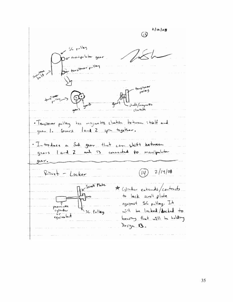
Figure 9: Permanent Manipulator Gear Sketch A manipulator gear is permanently attached to the scroll plate. This gear is operated on a separate pulley system with a gear ratio and tensioner pulley mechanism. This mechanism consists of two different ratio gears that sit on opposite sides of the belt. They operate on magnetic clutches and when engaged, drive that ratio to the manipulator gear which turns the scroll plate at the desired speed. The tensioner pulley system itself is able to move and rotate in order to keep tension and provide adequate belt contact. When not engaged, this system is able to spin freely. The scroll plate is locked using an electromagnet imbedded into the scroll plate that locks itself to the supercharger pulley.

12
3.4 V-belt System (Design 4)
Figure 10: V-belt System Sketch For this design a V-belt CVT system will be installed between the supercharger shaft and the original supercharger pulley. This system will incorporate current technologies and guarantees system accuracy. This system will also eliminate the need to modify the tensioner pulley to cover the ranges of system length due to varying the supercharger pulley diameter.

13
3.5 Packaged Gear Ratios (Design 5)
Figure 11: Packaged Gear Ratios Sketch The supercharger shaft is extended through the scroll plate and attached to two staggered and different driving gears. Each of these gears is part of its own gear ratio system on either side of the supercharger shaft. One side is used to speed up the scroll plate and the other is used to slow it down. Each gear system is operated by a magnetic clutch and is attached to a small driveshaft that feeds back to the scroll plate, spinning at the desired rate. When neither clutch is engaged the system spins freely. The whole system is housed in an enclosure that prevents the component driveshafts from spinning around the supercharger driveshaft. The scroll plate is locked using an electromagnet imbedded into the scroll plate that locks itself to the supercharger pulley. 4. Concept Selection. From a narrowed down selection of 20 design combinations, the top five designs were chosen. The designs were checked to see which were the most feasible and to make sure they would fulfill the desired goals of the project. These five concepts were then compared in a Pugh chart using design criteria. The engineering specifications that were previously discussed were not used to compare the concepts because each concept must fulfill these requirements. The specifications were given a weighted system as seen in the Pugh chart (Table 3, pg.14). The concept that was chosen for the alpha design had the highest point score according to this chart.

14
Design Criteria Wei
ght
Pulley System
Hydraulic Drill Design
Permanent Manipulator Gear
Packaged Gear Ratios
V-belt System
Aesthetics 1 -1 1 - 3 1 Cost 1 -2 -3 D 0 1 Safety 2 1 -1 A 2 0 Size 3 2 1 T 1 -2 Weight 2 0 -1 U -1 -2 Manufacturability 3 0 -1 M 0 0 Simplicity 3 1 -3 - 1 1 Total Points 8 -15 0 11 -5
Table 3: Pugh Chart Several advantages and disadvantages are associated with the top five designs. The pulley system it is very compact and would be fairly lightweight. However, due to the many parts of this system the cost to make it would be very high. The hydraulic drill is a complex design and therefore would be costly and not very easy to manufacture. The V-belt system is cost efficient because this technology already exists. Due to implementing a previously existing system it would take up a large amount of space and would be heavy. The chosen concept for the alpha design is the packaged gear ratio. This design was chosen because it combines all the engineering design criteria into a very simple and safe design. Composing the system completely of gears also helps to reduce the chance for failure. The main disadvantage of the chosen design is that the gears will add a significant amount of weight.
5. Overall Concept Description
5.1 Parameter Analysis Setting out to analyze the system, we determined it was necessary to calculate the minimum shaft diameter. The yield stress of 12L14 Steel was used (415 MPa). The smallest possible shaft diameter was determined to be 0.012 m. This shaft size is smaller than possible bore sizes of gears so the stresses that the shaft will incur are acceptable. A stress analysis was done to complete this process with the maximum torque of 10 Nm. The maximum moment used was calculated using the weight of the gears as well as the clutches. Inertial forces were determined to be negligible because the system’s change in speed occurs in under 0.05 sec and is very small. Using Equation 1, the shaft diameter was calculated.
Eq. 1
From here, the next goal was to determine dimensions for the spur gears. We used the following equations to determine the gear ratios needed to increase or decrease the scroll plate six revolutions over two seconds:

15
Eq. 2
Eq. 3
Eq. 4
Eq. 5
Eq. 6
Eq. 7
Eq. 8
where ωi is rotational speed of component i, Ni is number of teeth on gear i, Di is pitch diameter of gear i, xi-j is distance between centers for gears i and j, and ωSC and ωSP are the rotational speeds of the supercharger and scroll plate, respectively. Equation 3 was used to calculate the rotational speed of the supercharger shaft extension, the system input, and gear 1. Then equations 4, 6 and 7 were used to calculate the final output speed of the scroll plate. It was important to calculate the distance between centers, equations 5 and 8, to make sure that the system would be aligned properly. Using these equations, we first calculated system component speeds at the lowest supercharger speed (800 RPM) where the longest actuation time would occur. This would ensure that all actuation times would be within the two second time period under any driving conditions. We then checked all system component speeds at 5000 RPM to make sure they were within the limits of the clutching system. Once the gear ratio approximations were determined, we began looking for catalogued gears to order. One limiting parameter we had while selecting gears was the distance between gear centers. The distance between the scroll plate center and its accompanied gear must equal the distance between the opposite two gears. Keeping this in mind, we selected multiple gear combinations that fit this criterion. We then ran these gears back through equations 2-8 to calculate their actuation times. To minimize stresses at higher RPMs, we selected the combination of gears that had the longest actuation time under two seconds. Since we then had the gear selection for one type of actuation (increase/decrease), we used the same method to determine the other actuation. A full table of these calculations can be found in Appendix B. When considering high speed gearing applications, it is important to consider that a lubrication system will be necessary for a metal to metal gearing system. To try and simplify our actuation design, we chose to use Delrin plastic gears instead of metal gears. This will eliminate the need for a circulating lubrication system.

16
A stress analysis of the chosen gears was performed using the Lewis equation for failure. A flexural stress of 1.13 GPa for Delrin Plastic was used to ensure the gears would not fail. Equation 9 shows the stress equation that was used. By applying a safety factor of 2 it was determined that the stresses seen by the gears would be acceptable.
Eq. 9 Through an analysis using CES Sofware it was determined that the best material to be used for the shaft was Wrought aluminum alloy, 7055, T77511 and for the gears Epoxy/Aramid Fiber, UD Composite, 0o Lamina. The manufacturing processes determined for the production of the gears is water jet cutting and for the shafts is rolling. Using SimaPro Software, an analysis of environmental sustainability was completed. It was determined that Aramid Fiber would have the greatest impact on the environment. This material is still recommended to be used though due to its life cycle abilities. The final design has an assembly efficiency of 77.5%. Currently all parts must be made of separate materials and move relative to each other. This fact along with the high efficiency was used to determine that the current design cannot be redesigned to improve efficiency A safety analysis was conducted for our final design. Using DesignSafe software for a risk assessment as well as FMEA, we were able to identify potential risks/failures of our design. These two methods encompass the failures introduced by people outside of our final design and working with our final design as well as the failures of the system itself through various modes of failure. The major results of this analysis can be found in Appendix F. The biggest risk encountered by our design comes from the binding of components ceasing rotation. Any failure that results in the stopping of rotation results in a major failure for our system with a maximum damage scenario. We have established these risks as a result of our assessments. A regular and systematic schedule of maintenance could reduce the risk of a system bind from occurring. We also would recommend that in any future iterations of our design that this risk should be highlighted as a major concern and the introduction of safety components that isolate this binding should be incorporated. The risk to people by a failure is minimal because of our introduction of a housing, which isolates the rotating mechanisms from outside contact.
5.2.1 Alpha Design Description After running calculations, we were able to derive an ideal model design. The main difference between our alpha design and our original concept is the elimination of the magnetic scroll plate. Instead of the magnetic scroll plate, a third component function has been designed to rotate the scroll plate at the same speed as the supercharger using a 1:1 gear ratio. With this addition, we have eliminated the need for speed sensors because it was determined to be outside of the scope of this project. An assembly of our alpha design is found in Figure 12. A dimensioned drawing for each individual part can be found in Appendix C.

17
Figure 12: Alpha Design Custom View
Figure 13: Alpha Design Top View

18
Figure 14: Alpha Design Isometric with Casing The three internal gear mates provide the three functions necessary: speed up, slow down, and constant (relative to the supercharger shaft). These gear ratios then drive the component shafts that spin the scroll plate at the desired speed. Each shaft is operated using an electromagnetic clutch. When desired, one of the clutches will activate and its corresponding shafts will be locked. When a different actuation is desired, that clutch will disengage and another will engage. The component shafts have been moved to one side of the model to save space. A casing unit has also been designed to enclose the actuator to keep it clean and provide support to the shafts with bearings. A properties table of all of our selected components can be found here: GEARS
Quantity RUSH Part No. Material Diameter (in) Bore (in) Teeth
1 AP1260 Delrin Plastic 5 0.75 60
1 AP1221 Delrin Plastic 1.75 0.625 21
4 AP1215 Delrin Plastic 1.25 0.625 15
2 AP1266 Delrin Plastic 5.5 0.75 66
1 AP1269 Delrin Plastic 5.75 0.75 69
1 AP1212 Delrin Plastic 1 0.5 12
SHAFTS
Quantity MISUMI Part
No. Material Diameter (in) Length
(in) Step Length
(in) Step Diameter (in)
1 U-PSFR Nickel Plated 1045
Steel 0.75 6.5 - -
2 U-PSFR Nickel Plated 1045
Steel 0.63 6.5 - -
1 U-PSFRA Nickel Plated 1045
Steel 0.63 6.5 1.25 0.5

19
BEARINGS
Quantity MISUMI Part
No. Inner Diameter (in) Outer Diameter
(in) Height (in)
2 SB6903ZZ 0.669 1.18 0.28
5 SB6902ZZ 0.59 1.1 0.28
1 SB6901ZZ 0.47 0.94 0.24
HOUSING
Quantity Material Length (in) Width (in) Height (in) Thickness (in)
1 Aluminum 5.625 8.5 7.5 0.25 We chose gears made from Delrin plastic, manufactured by Rush Gears Inc., to eliminate the necessary lubricating system associated with metal gears. The shafts were selected to be made from nickel plated steel for strength and sampled from MISUMI. We selected standard ABEC-1 bearings from MISUMI to be placed in the housing to support each shaft.
5.2.2 Final Design Description After researching magnetic clutches, we realized that current technologies did not allow for the production of our ideal alpha design. In order to fully satisfy the needs of the EPA it was necessary to come up with a final design that could be made from current, off-the-shelf components. The main differences between our final design and our alpha design are: the addition of currently manufactured magnetic clutches, step-down gearing systems to reduce shaft RPM, and a third support plate. The step-down gearing systems are necessary for the application of current magnetic clutch technologies. A dimensioned drawing for each individual part can be found in Appendix D.
Figure 15: Final Design Custom View

20
Figure 16: Final Design Top View
Figure 17: Final Design Isometric As in the alpha design, the internal gear mates provide the three functions necessary: speed up, slow down, and constant (relative to the supercharger shaft). The key features of the final design are: 4500RPM rated magnetic clutches and the ability to be built with current off-the-shelf components. A fully-enclosed casing unit has also been designed for the final design. A properties table of all of our selected components can be found in Appendix E.

21
Again, we chose gears made from Delrin plastic, manufactured by Rush Gears Inc., to eliminate the necessary lubricating system associated with metal gears. The shafts were selected to be made from nickel plated steel for strength and sampled from MISUMI. We selected standard ABEC-1 bearings from MISUMI to be placed in the housing to support each shaft. It is important to note that the dimensions of our final design are approximately 17.72in wide x 10.18in tall x 10.75in long. With this in mind, it is doubtful that the final design will easily fit into any current engine bay. However, since no size requirements were given by the EPA, size should not affect meeting customer requirements.
5.3 Prototype Description The prototype for our system will be separated into a physical prototype and a virtual prototype. The virtual prototype is the main focus for our design and will be a direct modeling of our final design. The physical prototype, deemed unnecessary by our sponsor, will be used mainly as a demonstration tool to aid those not associated with the project in understanding what the virtual prototype communicates. The physical prototype will be a slightly modified, life-size model of our ideal prototype. It will not include magnetic clutches or bearings and thus will require extra shaft length to slide gears in and out of contact. It will not operate in the desired RPM range or support true operational forces due to time and money constraints. The supercharger/input shaft will be driven by hand so no external motor will be necessary. We have decided to use this method for demonstration purposes so that the functions of the system would be more easily seen and understood. The prototype will be comprised of dimensionally accurate gears with wooden dowels as shafts. Support plates and gears will be made out of Plexiglas. The supercharger pulley will be replaced by reference lines on the input shaft and scroll plate to demonstrate scroll plate movement relative to the input shaft. The virtual prototype is a fully accurate model of the final design as described in section 5.2.2. The virtual prototype has been modeled in SolidWorks 2007 to generate a visual assembly. The assembly file is dimensionally accurate and fully able to simulate system motion for a given input motion. In addition, the model has been placed in COSMOSmotion, an extension of the SolidWorks program, and tested for system performance under the three configurations: speed-up, slow-down, and constant (idle). The virtual prototype passed all phases of testing and was proven effective of meeting customer requirements in the COSMOSmotion software.
5.4 Fabrication Plan The full design will not be completely prototyped with the physical model and our sponsor has communicated the lack of need for a physical prototype, therefore, we will be using our physical prototype simply as a demonstration tool. Because of this, the physical prototype is very simple in design and the materials used in it do not relate to the materials of the final design. Our goal in fabrication is to choose inexpensive materials that will be able to easily show what we seek to demonstrate and then keep the machining process as simple as possible. The following is a chart describing the parts of the physical prototype, the materials they are made up, the costs of the parts, and the processes used to create these parts.

22
Part Material Cost Process Gears Plexiglas $40.00 Laser Cutter Shaft Wood $4.00 Band Saw Housing Plexiglas $10.00 Laser Cutter The wooden dowels will serve as the shaft for our physical prototype. On these dowels, Plexiglas gears will be mounted using adhesives. The crank shaft and mock supercharger pulley will be constructed like the shaft and gears using wood dowels and Plexiglas. The design for the system has taken into account the fabrication process so no re-design was necessary.
5.5 Validation For the proper validation of our design, we had to focus on the testing of our virtual model. Our final design was modeled in SolidWorks and COSMOSMotion, a component of the SolidWorks package, was used to simulate our design under conditions it would see in the field. To do this, we imported our assembly into COSMOSMotion, Figure 18 (pg.23), and established which parts would be moving and which parts would be assumed as grounded. The housing plates were the only pieces of our design that would be considered stationary. The gear mate of the shaft for validation was enabled and the other shaft gear mates were disabled to ensure that only one magnetic clutch would be simulated at a time. This would allow us to test each system separately to ensure that each clutch and drive system would meet the required specifications set by its design.

23
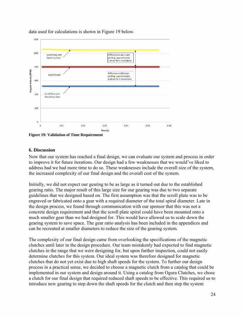
Figure 18: COSMOSMotion Screenshot After establishing a drive to test, a motion of both 800 and 5000 RPM were separately implemented on the supercharger shaft. The system was simulated at each of these speeds and plots were created of the supercharger shaft’s angular velocity as well as the scroll plate’s angular velocity over the established two second standard. A small time increment was used in the simulation to ensure accurate results. These results were then exported to Microsoft Excel for further analysis and comparison. By using the exported data from COSMOSMotion the time for the scroll plate to rotate six full rotations relative to the supercharger was determined. For the speed up gear ratio the time was 1.46 seconds and for the slow down gear ratio the time was 1.28 seconds. Both of these times are under the customer requirement of 2 seconds. The plot of this
24
data used for calculations is shown in Figure 19 below.
Figure 19: Validation of Time Requirement
6. Discussion Now that our system has reached a final design, we can evaluate our system and process in order to improve it for future iterations. Our design had a few weaknesses that we would’ve liked to address had we had more time to do so. These weaknesses include the overall size of the system, the increased complexity of our final design and the overall cost of the system. Initially, we did not expect our gearing to be as large as it turned out due to the established gearing ratio. The major result of this large size for our gearing was due to two separate guidelines that we designed based on. The first assumption was that the scroll plate was to be engraved or fabricated onto a gear with a required diameter of the total spiral diameter. Late in the design process, we found through communication with our sponsor that this was not a concrete design requirement and that the scroll plate spiral could have been mounted onto a much smaller gear than we had designed for. This would have allowed us to scale down the gearing system to save space. The gear ratio analysis has been included in the appendices and can be recreated at smaller diameters to reduce the size of the gearing system. The complexity of our final design came from overlooking the specifications of the magnetic clutches until later in the design procedure. Our team mistakenly had expected to find magnetic clutches in the range that we were designing for, but upon further inspection, could not easily determine clutches for this system. Our ideal system was therefore designed for magnetic clutches that do not yet exist due to high shaft speeds for the system. To further our design process in a practical sense, we decided to choose a magnetic clutch from a catalog that could be implemented in our system and design around it. Using a catalog from Ogura Clutches, we chose a clutch for our final design that required reduced shaft speeds to be effective. This required us to introduce new gearing to step down the shaft speeds for the clutch and then step the system

25
speed back up for the final scroll plate gear pairing. This system seems a bit over-complicated now and given more time we would like to reinvestigate how to optimize this and reduce the overall number of gears. The cost of the system is another weakness in our design that obstructed us from creating a final design physical prototype. Each magnetic clutch was around $800 and the gearing ranged up to $200 per gear. These costs would of course be minimized in a full-scale production of this design, but we would still like to further reduce these based on the recommendations above. These weaknesses of our system do not take away from its overall strengths. Our team is one of our most intense critics, but overall, we were very happy with our final design. The design was fully functional and achieved all of the required specifications and guidelines brought to us by the Environmental Protection Agency. This success is outlined in further detail in the assessment section of this report. Our design was also very robust and safety from failure was ensured during material selection processes. A major strength of our overall design was that it was a completely new idea without any former precedent as guidance. There are no such technologies on the market from which to take strengths and weaknesses and further improve which forced us to create new technologies. Our team was presented with an open-ended problem and was given full independence in the solution process. This process included the entire gearing concept and followed this down to the specific final design. The design’s greatest strength is that it accomplishes all the desired tasks and specifications with a significant margin of success while it is a completely new technology. Our team would have done a few things differently specific to the design process if we could go through the process again. Most of our encountered problems were due to the time constraints and time crunch that we experienced towards the end of the process. If earlier design creation and prototyping would have taken the place of overly extensive design problem establishment, we would have had more time to investigate obstacles as they came along and improve the efficiency of our final design. We also would have moved quicker to establish contact with our sponsor and the resources delivered from our sponsor to aid in our design procedure.
7. Recommendations Overall, our system was an effective means for accomplishing the specified tasks presented while also satisfying all of the design constraints. If our design were taken and continued to be improved with further design iterations, the overall size of the gears can be minimized based on the new knowledge that the scroll plate spiral does not need to be a part of the scroll plate gearing. This smaller gearing would enable the rest of the system to decrease proportionally, thus decreasing the cost of the system as well as the overall size. A further gear analysis should be conducted to ensure that the optimal gear sizes are selected to reduce the number of gears to a minimum. Complexities encountered late in the design process with the magnetic clutches hindered this process from being completed and the overall design efficiency could be improved with this in mind. The magnetic clutches should be further investigated as the optimal means for separate shaft engagement. During our design process, the idea of modeling this system off of an automotive

26
transmission was brought up, but our team could not properly investigate this due to both time and knowledge constraints of such a system. A further analysis could improve the system and reduce the complexities encountered with it. A final recommendation is that currently a binding in any shaft could lead to complete system bind. Our team has implemented the guidelines that a routine maintenance program could easily be established to avoid this from happening, but further iterations of the design process should look to find a way to isolate failures from becoming chain failures that affect the whole system. This would greatly reduce the overall risks as well as their accompanying severities on the design. 8. Summary. Current forced induction engines are wasting energy in the form of excess boost pressure. Specifically, a diesel engine with a supercharger has a decrease in system efficiency due to bleeding of excess boost pressure. One approach is to reduce or eliminate the production of excess boost pressure by manipulating the gear ratio between the engine and supercharger pulley by creating a CVT system. Manipulating the gear ratio can ensure that a target boost pressure is kept constant and energy waste is minimized. There are currently no technologies comparable to this approach. Current diesel engine setups use a serpentine belt system and new technologies will have to be developed for the addition of a CVT to manipulate gear ratios. Designs for a new system must be capable of maintaining all engine speeds for long periods of time. In this case, we will be taking existing system components and building onto them. This requires that our additions meet all the requirements of the current system components. The customer would like the extreme gear ratio transformation to occur within a two second time interval. Focus is being placed to have a purely mechanical system that is robust and efficient. Also, we will be looking to make a few changes to the supercharger pulley as possible. The concept generation was completed by deriving 20 designs using a functional decomposition chart and morphological chart. From these 20 designs the top five were chosen. These five designs were compared in a Pugh chart using design criteria. The best design was chosen as our alpha design. The packaged gear ratio system is comprised of an extension of the supercharger shaft and the addition of two driving gears to this shaft. From these driving gears, a gear ratio is established that connects mechanically to the scroll plate to alter its speed and thus change the pulley radius. Electromagnetic systems and a controller are used to dictate this actuation. The alpha design has been determined and specifications of this have been established. Calculations were run using engineering analysis to ensure that the design was both feasible and practical. The changes from the alpha design to the original concept include: the elimination of the scroll plate’s magnetic system, which has been replaced by a 1:1 speed ratio for simplicity, the addition of housing for support, the elimination of speed sensors based on the assumption that this could be easily calculated externally outside of the scope of our project, and the gears’

27
physical positioning. Currently the alpha design is an ideal design which incorporates clutches that are not currently manufactured due to the high speed requirement. In addition to the alpha design, a final design that incorporates clutches that are currently produced was also developed. This design utilizes all off the shelf components allowing it to be built now. The prototype for our project is split into a physical demonstration model and a virtual prototype. The virtual prototype is the main deliverable for our sponsor and directly resembles the final design. The physical prototype is a very simple model, modeled after the ideal design, that creates a physical representation of our virtual prototype to aid in demonstration purposes for those not closely associated with the project. 9. References. Stuhldreher, Mark and Moskalik, Andrew. EPA Interview. 15 Jan. 2008. [1] <http://auto.howstuffworks.com/cvt2.htm>. 18 Feb. 2008. [2] <http://www.speedchaser.net/images/New_Pulley/Pulley03.JPG>. 18 Feb. 2008. [3] <http://patft.uspto.gov/netacgi/nph-Parser?Sect1=PTO1&Sect2=HITOFF&d=PALL&p=1&u=%2Fnetahtml%2FPTO%2Fsrchnum.htm&r=1&f=G&l=50&s1=4848663.PN.&OS=PN/4848663&RS=PN/4848663>. 18 Feb. 2008.

28
10. Appendix Appendix A: Sketches

29

30

31

32

33

34
35

36

37
Appendix B: Gear Calculations

38
Appendix C: Engineering Drawings-Alpha Design

39

40

41

42

43

44

45
Appendix D: Engineering Drawings- Final Design

46

47

48

49

50

51

52

53

54

55

56

57

58

59

60

61

62

63

64

65

66

67

68
Appendix E: Bill of Materials

69
Appendix F: Design Analysis Assignment from Lecture 1. Material Selection Assignment CES software was used to determine the ideal materials to be used for the final design. The major constraints implemented were cost, yield strength for the shaft material, and flexural strength for the gear material. The top materials for the shaft were determined to be wrought aluminum alloy, carbon steel AISI 1030, low alloy steel AISI 4130, wrought martensitic stainless steel, nodular graphite cast iron. The top materials for gears were epoxy/aramid fiber, BMI/HS carbon fiber, Cyanate Ester/HM carbon fiber, and Epoxy/S-Glass Fiber. The final choices were based on the material that was the cheapest but could still with stand the necessary stresses. The material selected for the shafts was wrought aluminum alloy and for the gears was aramid fiber. For at least two major components of your final design: 2. Design for Assembly part No. of
consecutive operations
Handling Code
Handling Time per Part
Insertion Code
Insertion Time
Operation Time
Housing 1 10 1.5 00 1.5 3 1Support Plates
3 10 1.5 01 2.5 12 3
Gears 22 10 1.5 01 2.5 88 22Shafts 13 10 1.5 01 2.5 52 13Bearings 18 0 1.13 01 2.5 65.34 18Clutches 3 10 1.5 01 2.5 12 3 Efficiency 232.34 60
0.7747 The calculation of our assembly efficiency can be found in the table above. This took into account the number of operations, handling time, insertion time, and minimum number of parts. We calculated having a total operation time of 232.34 seconds, with 60 parts. The efficiency of this assembly is 77.5%. This relatively high efficiency supports our conclusion that the final design cannot be redesigned to improve assembly efficiency. Each part in our design plays a specific operational role that cannot be substituted or eliminated, nor combined with another part. Each joint in our system combines two parts of different materials. This information, along with our original design efficiency leads us to believe that it cannot be improved any more.

70
3. Design for Environmental Sustainability

71
72
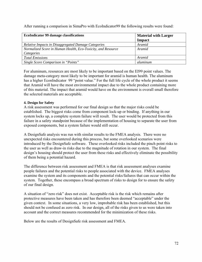
After running a comparison in SimaPro with EcoIndicator99 the following results were found: EcoIndicator 99 damage classifications Material with Larger
Impact Relative Impacts in Disaggregated Damage Categories Aramid Normalized Score in Human Health, Eco-Toxicity, and Resource Categories
Aramid
Total Emissions Aramid Single Score Comparison in “Points” aluminum For aluminum, resources are most likely to be important based on the EI99 point values. The damage meta-category most likely to be important for aramid is human health. The aluminum has a higher EconIndicator 99 “point value.” For the full life cycle of the whole product it seems that Aramid will have the most environmental impact due to the whole product containing more of this material. The impact that aramid would have on the environment is overall small therefore the selected materials are acceptable. 4. Design for Safety A risk assessment was performed for our final design so that the major risks could be established. The biggest risks come from component lock-up or binding. If anything in our system locks up, a complete system failure will result. The user would be protected from this failure in a safety standpoint because of the implementation of housing to separate the user from exposed components, but a system failure would still occur. A DesignSafe analysis was run with similar results to the FMEA analysis. There were no unexpected risks encountered during this process, but some overlooked scenarios were introduced by the DesignSafe software. These overlooked risks included the pinch point risks to the user as well as draw-in risks due to the magnitude of rotation in our system. The final design’s housing should protect the user from these risks and effectively eliminate the possibility of them being a potential hazard. The difference between risk assessment and FMEA is that risk assessment analyses examine people failures and the potential risks to people associated with the device. FMEA analyses examine the system and its components and the potential risks/failures that can occur within the system. Together, these encompass a broad spectrum of risks to design for to ensure the safety of our final design. A situation of “zero risk” does not exist. Acceptable risk is the risk which remains after protective measures have been taken and has therefore been deemed “acceptable” under the given context. In some situations, a very low, improbable risk has been established, but this should not be confused as zero risk. In our design, all of the risks given to us were taken into account and the correct measures recommended for the minimization of these risks. Below are the results of DesignSafe risk assessment and FMEA.

73

74
5. Manufacturing Process Selection For use in all of our gears, we selected the material Epoxy/Aramid Fiber , U D Composite, 0 deg Lamina. The manufacturing process we have selected for the gears is water jet cutting. We

75
selected this process because it has high precision needed for tooling gears. It also has a relatively low equipment cost, and little to no retooling costs. Using the CES process selector, we confirmed that water jet cutting is the best choice. CES confirmed that material we have chosen can be effectively machined using water jet cutting. It also confirmed the machineable part thickness. A water jet cutter can cut materials up to 0.98 inches thick. The gears we have designed are no thicker than 0.75 inches. For use in the shafts, we have selected the material Wrought Aluminum Alloy, 7055, T77511. The manufacturing process we have chosen for the shafts is rolling. We chose this for its consistency and continuous forming. CES confirmed that the process we should select is shape rolling. The sectional thickness is not a problem for this process. We have concluded that the process should consist of a hot shape roll, as well as a cold shape roll. The hot roll will shape it to its general form, while the cold roll will give it a precise tolerance.

76
Appendix G: Engineering Change Notices Engineering Change Notice: Shaft Addition WAS: Note: Clutch system was implemented so step down gears were required to achieve acceptable shaft speeds. See Appendix D for detailed engineering drawings. Engineering Change Notice: Gear Addition WAS: Note: Clutch system was implemented so step down gears were required to achieve acceptable shaft speeds. See Appendix D for detailed engineering drawings.
IS: Project: CVT Ref Drawing: Top View Engineering Team: 31 4/3/08 Sponsor: EPA/M. Stuhldreher 4/10/08 IS: Project: CVT Ref Drawing: Top View Engineering Team: 31 4/3/08 Sponsor: EPA/M. Stuhldreher 4/10/08

77
Engineering Change Notice: Clutch Change WAS: Note: Clutch system was implemented so step down gears were required to achieve acceptable shaft speeds. See Appendix D for detailed engineering drawings. Engineering Change Notice: Size Change WAS: Note: Clutch system was implemented so step down gears were required to achieve acceptable shaft speeds. See Appendix D for detailed engineering drawings.
IS: Project: CVT Ref Drawing: Top View Engineering Team: 31 4/3/08 Sponsor: EPA/M. Stuhldreher 4/10/08 IS: Project: CVT Ref Drawing: Top View Engineering Team: 31 4/3/08 Sponsor: EPA/M. Stuhldreher 4/10/08

78