vaya control module - docs.colorkinetics.com · 10/16/17 philips solid-state lighting solutions...
TRANSCRIPT
10/16/17 Philips Solid-State Lighting Solutions Confidential Page 1 of 12
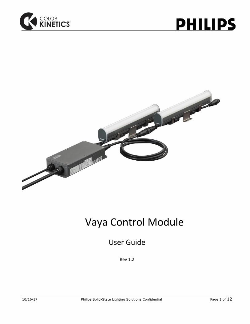
Vaya Control Module
User Guide
Rev 1.2

10/16/17 Philips Solid-State Lighting Solutions Confidential Page 2 of 12
Getting Started with Vaya Control Module Vaya Control Module is an (IP66) outdoor rated data supply for Philips Vaya direct view fixtures. The slim housing takes 24V DC power and combines it with either KiNet or DMX512 control data, to two separate, fuse-protected, outputs ports. Twist-lock (CE/CQC version) Snap-lock (Global version) panel mount connectors ensure a secure / fast and reliable connection to the Vaya Leader-Jumper cables and fixtures.
Unscrew the lid using a 2.5mm hex key.
Connect either to the KiNet or DMX port via standard Cat5e or higher Ethernet cable, and wire the 24V DC constant voltage supply to the 2pin terminal block as indicated in the image above.

10/16/17 Philips Solid-State Lighting Solutions Confidential Page 3 of 12
Typical Vaya Control Module Installation A typical installation includes one or more Vaya Control Modules connected to a control server – e.g. Philips Color Kinetics Light System Manager (KiNet) / Philips Color Kinetics iPlayer 3 (DMX) or any 3rd party DMX controller. Multiple Vaya Control Modules are connected in a star configuration via network switches (KiNet) or opto-splitters (DMX):
10/16/17 Philips Solid-State Lighting Solutions Confidential Page 4 of 12
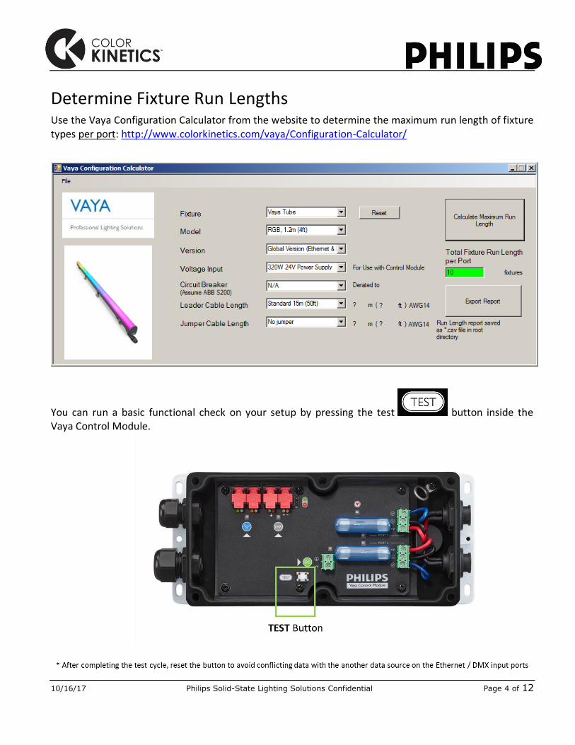
Determine Fixture Run Lengths Use the Vaya Configuration Calculator from the website to determine the maximum run length of fixture types per port: http://www.colorkinetics.com/vaya/Configuration-Calculator/
You can run a basic functional check on your setup by pressing the test button inside the Vaya Control Module.

10/16/17 Philips Solid-State Lighting Solutions Confidential Page 5 of 12
Configuration Download the latest version of QuickPlay Pro (v1.5.1 or higher) from the Philips Color Kinetics website to configure the Vaya Control Module: http://www.colorkinetics.com/support/addressing/
Ethernet Mode Configuration (KiNet) Set your computer’s IP address to 10.x.x.x, and subnet mask 255.0.0.0.

10/16/17 Philips Solid-State Lighting Solutions Confidential Page 6 of 12
Connect an open ended RJ45 cable between your computer’s Ethernetport and the Vaya Control Module’s KiNet port (there is no need to strip the wires, the tooth clamps will pierce the wire jackets upon closing)
When configuring multiple units, connect the computer to the master network switch, and wire in the same way as above to the individual Control Modules.
QuickPlay Pro will automatically detect all connected units and display them in the “Controller” drop-down menu with their IP address.

10/16/17 Philips Solid-State Lighting Solutions Confidential Page 7 of 12
Under PDS Configuration, you can read back and set the input mode, node count (per port), pixel resolution, start address etc:

10/16/17 Philips Solid-State Lighting Solutions Confidential Page 8 of 12
Field Description Remark
Name Show / Edit the active Control Module’s name
Rename the Control Module to a meaningful description for easy identification in case of follow-ups or trouble-shooting
IP Address Show / Edit the active Control Module’s IP address
The fields to the right also show the device’s Serial Number, MAC Address and Protocol version
KiNet Universe Show / Edit the active Control Module’s KiNet universe numbers
This should be “0” in most cases, please only change this setting under consultation from your local System Expert
Node Count Discover connected number of individually controllable nodes (150mm/6in sections) on both ports of the Control Module
Refers to the total number of phyically controllable nodes per chain on Port 1 / Port 2 and does not distinguish the physical length of the connected fixtures or its “Pixel Resolution” setting;
E.g. the above shown “8 Nodes” could be either 1x 1.2m/4ft fixture or 4x 0.3m/1ft fixtures
Input Mode Color Resolution of Input Data Default is set to 8-bit
Nodes / Port 1 & Port 2 Manually set the total number of individually controllable nodes per port
Only required if “Node Count” functionality is not available (e.g. when in DMX mode) or incorrect
Fuse Status / Port 1 & Port 2
Indicates the status of each port’s output fuse inside the Control Module
Should read “Fuse OK” – otherwise, replace fuse (8A 125V)
Pixel Resolution Set length of individually controllable pixel (minimum 150mm/6in)
Not recommended to change from default 150mm/6in resolution setting when final control protocol is Kinet!
(Kinet-based software not yet updated to manage lower resolution settings on Vaya Tube).
Startup Red / Green / Blue
Set startup values (0-255) for each channel upon power-up without data connection
Default setting is 10 / 10 / 10
(DMX) Start Address # Set DMX start address of the active Control Module (Port 1)
Only applies when final control signal is DMX (in Kinet mode automatically resets to start address “1”):
Set in increments of 3 (for both RGB and White/Mono versions)
Read Read back current settings
Program Write settings to Control Module
Program All Discovered Vaya Control Modules
Write simultaneously to all connected Control Modules
You can now test and commission your Vaya Tube installation by using the Test Channel or fixture tabs Fixed Color / Color Wash / Streak.
Repeat above steps per Control Module / Network Switch cluster as needed per site.

10/16/17 Philips Solid-State Lighting Solutions Confidential Page 9 of 12
DMX Mode Configuration (DMX512) Connect your computer’s USB port to the Control Module via SmartJack Pro (Item Number: 103-000024-00 / 12NC: 910503700582)
Connect an open ended RJ45 cable between the SmartJack Pro and the Vaya Control Module’s DMX port (there is no need to strip the wires, the tooth clamps will pierce the wire jackets upon closing)
When configuring multiple units, connect the SmartJack Pro to the DMX splitter, and wire in the same way as above to the individual Control Modules. Only applicable if all connected Control Modules are set to the same configuration.
Note: When using the Philips Color Kinetics SmartJack Pro to configure the Vaya Control Module, remember to switch the Orange/White (CK RJ45’s Data-) and Orange (CK RJ45’s Data+) wires. The Vaya Control Module shows ESTA standard wire coding.

10/16/17 Philips Solid-State Lighting Solutions Confidential Page 10 of 12
QuickPlay Pro will automatically detect the connected SmartJack Pro unit and display it in the “Controller” drop-down menu with its SN number.
Under PDS Configuration, you can set the node count (per port), pixel resolution, startup color and start address of the Vaya Control Module.

10/16/17 Philips Solid-State Lighting Solutions Confidential Page 11 of 12
Field Description Remark
Name Refers to the connected SmartJack Pro device
N/A in DMX mode
IP Address / MAC Address / KiNet Protocol version
N/A N/A in DMX mode
KiNet Universe N/A N/A in DMX mode
Node Count N/A N/A in DMX mode
Nodes / Port 1 & Port 2 Manually set the total number of individually controllable nodes per port
Refers to the total number of controllable nodes per chain on Port 1 / Port 2 and does not distinguish the physical length of the connected fixtures.
E.g. A 1x 1.2m/4ft fixture or 4x 0.3m/1ft fixtures configurations would both be shown as “8 Nodes” (see illustration)
Pixel Resolution Set length of individually controllable pixel (minimum 150mm/6in)
In DMX mode, this setting helps reduce the number of physically required DMX channels.
One resolution setting for the entire Control Module (Port 1 & Port 2).
Startup Red / Green / Blue
Set startup values (0-255) for each channel upon power-up without data connection
Default setting is 10 / 10 / 10
(DMX) Start Address # Set DMX start address of the active Control Module (Port 1)
Set in increments of 3 (for both RGB and White/Mono versions)
Program Write settings to Control Module
An 0.3m/1ft fixture always has “2 nodes” & an 1.2m/4ft fixture always has “8 nodes”, irrespective of the fixture’s “Pixel Resolution” setting
You can now test and commission your Vaya Tube installation by using the Test Channel or fixture tabs Fixed Color / Color Wash / Streak.
Repeat above steps per Control Module / Network Switch cluster as needed per site.

10/16/17 Philips Solid-State Lighting Solutions Confidential Page 12 of 12
After configurig the Vaya Control Module, it is recommended to note the configuration details on the device, for easy referencing during installation.
Removable serial number labels are provided on the device as additional reference option.
Notes: