vbn.aau.dk · 1 . ics. abstract— the use of integrated shipboard power sys-tem (sps) has greatly...
TRANSCRIPT

Aalborg Universitet
A Flexible Power Control Strategy for Hybrid AC/DC Zones of Shipboard Power Systemwith Distributed Energy Storages
He, Li; Li, Yong; Shuai, Zhikang; Guerrero, Josep M.; Cao, Yijia; Wen, Ming; Wang, Weiyu;Shi, JingrongPublished in:IEEE Transactions on Industrial Informatics
DOI (link to publication from Publisher):10.1109/TII.2018.2849201
Publication date:2018
Document VersionEarly version, also known as pre-print
Link to publication from Aalborg University
Citation for published version (APA):He, L., Li, Y., Shuai, Z., Guerrero, J. M., Cao, Y., Wen, M., Wang, W., & Shi, J. (2018). A Flexible Power ControlStrategy for Hybrid AC/DC Zones of Shipboard Power System with Distributed Energy Storages. IEEETransactions on Industrial Informatics, 14(12), 5496-5508. [8392448]. https://doi.org/10.1109/TII.2018.2849201
General rightsCopyright and moral rights for the publications made accessible in the public portal are retained by the authors and/or other copyright ownersand it is a condition of accessing publications that users recognise and abide by the legal requirements associated with these rights.
? Users may download and print one copy of any publication from the public portal for the purpose of private study or research. ? You may not further distribute the material or use it for any profit-making activity or commercial gain ? You may freely distribute the URL identifying the publication in the public portal ?
Take down policyIf you believe that this document breaches copyright please contact us at [email protected] providing details, and we will remove access tothe work immediately and investigate your claim.

1
Abstract—The use of integrated shipboard power sys-
tem (SPS) has greatly contributed to the next-generation vessels development. In this sense, how to realize the rea-sonable power distribution between hybrid zones in SPS is becoming one of the key problems to ensure system robustness and reliability. In this paper, a flexible power control strategy is proposed for the coordinated operation of the hybrid AC/DC zones in SPS. First, the interactive relationship of the AC/DC interface is analyzed, and the virtual inertia and capacitance are defined to reveal the interactive influence of the AC and the DC sub-grids, which leads to a new V-f droop principle. Then, the flexible control strategy is designed based on the droop principle as well as the characteristics of the analogous virtual syn-chronous generator (VSG), and the key parameters’ de-termination are discussed in detail, which can realize a proper assignment of cross-zone supportive power and improve the system dynamic response. In addition, the coordinated control loops are designed with the distribut-ed energy storages (DESs) and interlinking converters (ICs) for the implementation of the strategy. Finally, the proposed strategy is validated by the simulation, which shows that the strategy can enhance the power quality and dynamics of the hybrid zones and contribute to the robustness of the whole SPS.
Index Terms—Flexible power control; hybrid AC/DC
zones; virtual synchronous machine (VSG); distributed energy storages (DESs); shipboard power system (SPS)
NOMENCLATURE SPS Shipboard power system. ES Energy storage. DES Distributed energy storage.
This work was supported in part by the 111 Project of China under
Grant B17016, in part by the national Natural Science Foundation of China (NSFC) under Grant 51520105011, in part by the Huxiang Youth Talent Program of Hunan Province under Grant 2015RS4022, and in part by the Excellent Innovation Youth Program of Changsha of China under Grant KQ1707003.
L. He, Y. Li, Z. Shuai, Y. Cao, W. Wang and J. Shi are with the Col-lege of Electrical and Information Engineering, Hunan University, Changsha 410082, China. (e-mail: [email protected], [email protected], [email protected], [email protected], [email protected], and [email protected]).
J. M. Guerrero is with the Department of Energy Technology, Aal-borg University, 9220 Aalborg East, Denmark (e-mail: [email protected]).
M. Wen is with the Economic Research Institute of State Grid Hu-nan Electric Power Company, Changsha 410082, China. (e-mail: [email protected])
ICs Interlinking converters. MTGs Main turbine generators. MVAC Medium-voltage AC. MVDC Medium-voltage DC. VSG Virtual synchronous generator. H Inertial constant. f0 Reference frequency. P0
INV Equivalent input mechanical power. PREF
INV Output electromagnetic power. SIC Power rating of the inverter. CDC Capacitance of the DC side capacitor. VDC Voltage of the DC bus. P0
REC Input power of DC side. PREF
REC Output power to AC side. f Stable value of frequency. Δf Frequency variation. VREF Rated value of the DC voltage. ΔVDC Voltage variation. M Correlation coefficient of the AC frequen-
cy and the DC voltage. HVSG Virtual inertia constant. kDC Droop coefficient of DC zone. P0
DC Initial output power of DC source. PREF
DC Reference output power of DC source. ΔVVIR
DC Virtual voltage variation. DVSG Virtual damping coefficient of AC grid. PREF
DC,ES Reference power of ES unit in DC zone. kAC Droop coefficient of AC zone. P0
AC Initial output power of AC source. PREF
AC Reference output power of AC source. ΔfVIR Virtual frequency variation. DVDC Virtual damping coefficient of DC grid. PREF
IC Reference power of IC. Q Reactive power. QREF Reference reactive power. iES Output current of ES unit. iREF
d Reference current of d-axis. iREF
q Reference current of q-axis. SoC State of charge. Gvi Global variation index.
I. INTRODUCTION ITH the development of the shipboard power system (SPS), the electric-power based loads are widely used in SPS [1]-[3], and renewable sources, such as photovolta-
ic system and wind generation, are drawing the industrial at-
A Flexible Power Control Strategy for Hybrid AC/DC Zones of Shipboard Power System
with Distributed Energy Storages Li He, Student Member, IEEE, Yong Li, Senior Member, IEEE, Zhikang Shuai, Senior Mem-ber, IEEE, Josep M. Guerrero, Fellow, IEEE, Yijia Cao, Senior Member, IEEE, Ming Wen,
Weiyu Wang, Student Member, IEEE, and Jingrong Shi
W

2
tention to be implemented in SPS, which can improve the fuel efficiency and alleviate the increasing pressure of environmen-tal protection and demand of cost saving [4]-[6]. Due to the limited space and requirement of high reliability, regionaliza-tion is adopted to design SPS, which means various generators and loads are deployed and managed in different zones ac-cording to their functions and the format of current, so there are hybrid AC/DC zones operating in SPS, which are equipped with individual generators and energy storage (ES) units, and each zone can serve as a power reserve [7], [8]. Therefore, a feasible strategy is necessary to enable the hybrid zones to work in a coordinated way, which helps to better uti-lize the capability of mutual power support between hybrid zones and improves the stability of SPS.
At present, the energy management for SPS is mainly con-cerned from the regard of making a balance between the pow-er generation and the highly impulse power load. In [9] and [10], the typical multi-agent control principle is introduced to the shipboard system for the real-time load management, which can realize optimal regulation of the power generation and consumption in SPS, and this method is also friendly to the newly implemented equipment. Based on the principle of demand-side management, a method of optimal demand-side management and power generation scheduling is proposed in [11], which can improve ship energy efficiency, and contrib-ute to the optimal operation of SPS. The above method can effectively improve the SPS performance. However, these methods are highly dependent on the communication system and require the support of complex algorithms, which means the system reliability might be threatened during severe mari-time conditions. Considering the advantages of ES, there are other literatures focusing on utilizing the ESs in power man-agement of SPS. [12]-[15] utilize the heuristic algorithms, such as fuzzy logic method and predictive control method, to design the control strategies of ESs and effectively relieve the negative impact brought by high-power ramp rate loads. How-ever, the reported methods also require high-functioning cen-ter controller and the characteristics of zonal structure are not fully considered.
Nowadays, there are few energy management strategies de-signed for the hybrid zonal SPS. The power control approach-es in territorial power systems can be used for the reference of SPS. In general, the coordinated control strategy between AC and DC grids can be classified into two categories: distributed control and master-slave control. The distributed control main-ly adopts the principle of droop method, and determines the exchanged power between zones with the droop coefficient [16]-[19]. However, either V(f)-P droop or V2(f)-P droop fea-tures hard to calculate the proper droop coefficient and has a mediocre dynamic performance while the severe power dis-turbance occurs. By comparison, the master-slave control strategy can realize a reasonable power allocation based on the global information [20]-[22]. However, this strategy highly depends on the fast communication network thus the reliabil-ity is threatened. In addition, the ES units in SPS are generally installed near the loads and utilized to suppress the local pow-er variation. The potential of cross-zone power supporting of distributed energy storage (DES) is not fully exploited, which indirectly leads to the waste of ES capacity.
In this paper, a flexible power control strategy is proposed
for the coordinated operation of the hybrid AC/DC zones in SPS. With the strategy, different zones can provide flexible power support for each other with good dynamic performance. Thus, the stability and reliability of SPS can be enhanced and the DESs are efficiently utilized. The advantages of the strate-gy and the main contributions of this paper are summarized as follows:
1) A linearized power coupling relationship between the AC and the DC zones is expressed, which is based on the vir-tual inertia and the virtual capacitance and features a physical meaning.
2) A flexible power control strategy for hybrid zones is proposed, of which the detailed design is derived from the operating characteristics of AC and DC grids, as well as the principle of droop control. Thus, it is feasible to be imple-mented in practice and improve the dynamic performance of SPS.
3) Compared with global optimization methods, the pro-posed control strategy is free of high-bandwidth communica-tion network, which features high reliability and efficiently utilizes the DESs’ power supporting capability.
The main structure and content of this paper are summa-rized as follows. Section II introduces the configuration of the typical hybrid zones of SPS. The interactive power balance analysis is conducted in Section III, which can serve as the basis of the proposed strategy. Section IV discusses the flexi-ble power control strategy from the principle to the control loop’s design, and the main parameter features are also in-cluded. The comparative simulation results and discussions verify the theoretical analysis and are presented in Section V. Finally, the conclusions are given in Section VI.
II. CONFIGURATION OF THE HYBRID AC/DC ZONES IN SPS Fig. 1 shows a developed notional configuration of the hy-
brid AC/DC zones in SPS, which consists of three parts: AC zone, DC zone and interlinking converters (ICs) [23], [24]. As can been seen from Fig. 1, the AC zone contains main turbine generators (MTGs), high-power propulsion motor, ES units, and other general AC loads. The utility grid access is available in AC zone for the connection of SPS and onshore power grid. The DC zone also contains the power sources and typical DC loads. The high-power DC loads like pre-charging weapons and radars are implemented in DC zone to reduce power step transition. The data and command center is connected to DC bus due to the high reliability of DC grid. The hybrid zones are interlinked by ICs, which serve for the exchange of power flow between zones.
IC #1
n1/n2
Tr1
IC #2
n1/n2
Tr2
G
DC/ACLandgrid Breaker
AC loads
IG
Energy storageDC/DC
Bidirectional converter
MTGs/ATGs
AC Zone DC Zone
Interlinking converters
AC/DC interface AC
bus
Energy storage
Precharging weapon
DC/DCData and commond
center
DC loads
IGPropulsion
load 1
Propulsion load 2
DC bus
IGPropulsion
load
DC/DC
DC/AC
G
MTGs/ATGs
Fig. 1. One-line diagram of a notional hybrid AC/DC zones in SPS

3
The structure of hybrid AC/DC zone increases the power ef-ficiency since it reduces the power transfer stages. Consider-ing that there are high-power loads (e.g. propulsion load and electromagnetic weapon) installed in both zones, which may cause serious power variation compared with that of terrestrial microgrids, the global power sharing can be rather important to maintain the operating stability. Therefore, it is urgent to enable the hybrid zones to work in a coordinated way, which can exploit the power support ability of DES units.
It is worth noting that, there are two important types of all-electric SPS, i.e., the medium-voltage AC (MVAC) system and the medium-voltage DC (MVDC) system [9], [24]. The main power generators and propulsion loads can be connected to AC or DC buses due to the different choice of system type. Therefore, the hybrid AC/DC topology with more detailed characteristics will vary according to different systems which SPS adopts. The studied method should have generality for different types of SPS. Thus, considering that key technolo-gies can be cross-fertilized between terrestrial microgrids and SPS [5], without losing generality, we developed the notional structure of hybrid zones in SPS derived from well-accepted hybrid AC/DC microgrid structure, aiming at showing clear and intelligible concept of hybrid AC/DC gird for discussion. In this paper, the proposed strategy is based on the universal relationship of power balance, to realize good power sharing between AC and DC sections.
III. INTERACTIVE POWER BALANCE ANALYSIS BETWEEN AC/DC INTERFACE
The bidirectional converters, which are operating as the ICs between the hybrid zones, can transmit active power between different grids as required. When the power is transferred from the DC side to AC side, the IC can be regarded as a virtual synchronous generator (VSG) [25], and the dynamic power balance of the AC side will vary accordingly, which can be described by the swing motion equation as,
0 REFINV INV AC
0
2= − = ∆
H df P P Pf dt
(1)
where H is the inertial constant of synchronous generator; f0 is the reference frequency; P0
INV and PREF INV are the equivalent input
mechanical power and the output electromagnetic power, re-spectively.
Similarly, when the active power is transferred from AC side to DC side, the IC can be treated as a virtual DC capacitor to provide voltage support, of which the characteristics can be expressed by
0 REFDC DC DCREC REC DC
IC
= − = ∆C V dV
P P PS dt
(2)
where SIC is the power rating of the inverter; CDC is the capaci-tance of the DC side capacitor; VDC is the voltage of the DC bus; P0
REC and PREF REC are the input power of DC side and the out-
put power to AC side, respectively. Therefore, the IC is a converter that can change the operat-
ing state and power direction according to the requirements, of which the interactive power supporting balance is shown in Fig.2. Based on the power balance when the power is trans-ferred between different zones, combining (1) and (2) yields,
DC DC DC
0 IC
2=
C V dVH dff dt S dt
(3)
REFINV P
0INVP
+
-
DCVAC∆P
,f ω
0RECP
DC∆P
(VSG) (Virtual capacitor)
REFRECP
AC/DC interface
Fig. 2. Interactive power relationship for AC/DC interface
Equation (3) shows that on the premise of power balance, the emulation of inertial effect and capacitance effect can be obtained according to the direction of power flow through the IC, which reveals the coupling relationship between AC and DC system and will be discussed in the following.
Integrating both sides of (3) and assuming the frequency and DC voltage are both in reference value at the initial time, then the following equations can be obtained
DC
0 REF
DC DCDC
0 IC
2=∫ ∫
f V
f V
C VH df dVf S
(4)
2DC 0 REF( )= − +V M f f V (5)
IC
DC 0
4 ⋅=
H SM
C f (6)
where f represents the stable value of frequency after power disturbance in AC/DC interface; VREF is the rated value of the DC voltage; M is defined as the correlation coefficient of the AC frequency and the DC voltage.
Substituting f-f0=Δf and VDC -VREF = ΔVDC into (5) yields 2 VSG IC
DC REF DC0 DC
42∆ + ∆ = ⋅∆
H SV V V f
f C (7)
2VSG ICDC REF REF
0 DC
4∆ = − + ∆ +
H SV V f V
f C (8)
The equation (8) indicates that voltage variation and fre-quency change are coupled in a nonlinear way, and the cou-pling degree is significantly influenced by HVSG and CDC. Vir-tual inertia constant HVSG is used to quantitatively describe equivalent inertia provided by converters as well as illustrate the coupling relationship of AC frequency and DC voltage. More specifically, it can be deduced from Fig. 3 that, with larger value of virtual inertial constant HVSG and fixed CDC, the increase of Δf leads to larger ΔVDC with the same changing direction, vice versa, which implies that more active power should be released (larger ΔVDC in DC side) to provide more inertia support for AC side and this coincides with the physi-cal characteristics of the hybrid system. In contrast, the in-crease of CDC will impose a negative impact on the coupling relationship. Taking the point A (CDC =1mF) and B (CDC =9mF) as examples, it can be observed that when the frequen-cy is increased by 4Hz, the difference of corresponding DC voltage deviations can be as large as 0.692kV, and the smaller CDC corresponds to larger ΔVDC. The analysis above can be served as the reference of the determination of key parameters in the following control system.
Expanding equation (8) using Taylor series, we can obtain (9) below. Further, considering that AC frequency is varied in

4
a relatively small range (generally restricted within ±0.005p.u.), the terms equal to or higher than second order can be neglected. Therefore, a linearized relationship between AC frequency and DC voltage can be obtained for the AC/DC interface, as shown in (10) and (11):
Virtual inertial constant / 10- 3
(s)
-1.5
-1.0
4
-0.5
3
0
0
0.5
2 1
1.0
21 30 45-1 6-2 78-3 9-4 10
DC
volta
ge v
aria
tion
(kV)
X: 4 Y: 0.01
Z: 0.824
X: 4 Y: 0.01
Z: 0.132
CDC decreases from 1 mF to 9 mF
CDC increases from 9 mF to 1 mF
Voltage drop
Frequency drop
X: - 4 Y: 0.01 Z:- 1.05
C
X: - 4Y: 0Z: 0
D
Frequency variation (Hz) Fig. 3 Relationship among virtual inertial constant HVSG, DC capaci-tance CDC, frequency and voltage variation (settings: VREF=7kV, f0=50Hz).
22
DC 3REF REF2 8
∆ = ∆ − ∆ +M MV f fV V
(9)
DC REF 0REF
( )2
= + −MV V f fV
(10)
VSG ICDC
REF DC 0
REF
2
2
H SV f M f
V C fMMV
′∆ = ∆ = ⋅∆ ′ =
(11)
Fig. 4 gives the comparison between the nonlinear and line-arized descriptions discussed above. The slope of ΔV´ is ac-quired by taking the difference between (8) and (11). It can be observed that, the operation of linearizing by Tayler equation (shown in violet slope) just brings about little mismatch from the original value (shown in blue slope). With the increase of the frequency deviation, the mismatch, shown by ΔV´, will become larger but restricted as large as 0.039kV, which means the coupling relationship of ΔV and Δf can be presented using the linearized equation (10) in the normal operation condition.
-1 -0.8 -0.6 -0.4 -0.2 0 0.2 0.4 0.6 0.8 1-0.3
-0.2
-0.1
0
0.1
0.2
0.3
Original coupling relationship shown in equation (8)
Linearized coupling relationship shown in equation (11)
Δf (Hz)
ΔV´
ΔV
(kV)
Fig. 4 Comparison of the coupling degrees between Δf & ΔV using different description equations (CDC is 7.5mF, HVSG is 6×10⁻³s, and SIC is set equal to 15 MW)
For the sake of clarity, it is worth pointing out the differ-ence between the conventional modeling linearization and the linearized coupling relationship in this paper. Generally, the modeling linearization of AC and DC networks with multiple converters can be rather more complex, due to that parameters variation (i.e., X/R ration) and different operating scenarios should be carefully considered. However, different from the abovementioned conventional model linearization, we develop the linearized coupling relationship from the regard of power
balance for the hybrid-grid interface. Therefore, the conven-tional model linearization aims to build an order-reduced ma-trix to describe the inner operational features of AC or DC system, and the proposed method is aiming to describe the power coupling relationship at the interface between AC and DC system. The mentioned two-linearization operations are considered for different purposes and objectives.
IV. PROPOSED FLEXIBLE POWER CONTROL STRATEGY In this Section, the flexible power control strategy will be
introduced systematically. Firstly, the DESs power response in AC and DC zones are designed carefully in subsections A and B, respectively, where the output power is divided to local response and cross-zone response, and the parameters features are visualized discussed for determining proper values. Then, the IC reference power is accordingly designed to transmit the mutual support power for achieving flexible power sharing between hybrid zones, which also includes the control loops illustration for the practical implementation.
A. Power Response of DES in DC zone When there appears power shortage in the DC zone, which
might be caused by the operation of high-power apparatus, the DES unit located in the DC zone will be immediately activat-ed to compensate the power imbalance. Assuming the general droop principle is adopted for the DES, which can be de-scribed as
REF 0DC DC REF DC DC( )= − +P k V V P (12)
where kDC is the droop coefficient of DC zone; P0 DC and PREF
DC represent the initial output power and the reference output power of DC source, respectively.
Except for the response to the local power deviation, the DES in DC zone should also be responsible for the power de-mand of the opposite zone, i.e., the AC zone. More specifical-ly, the power demand mismatch in AC zone can be reflected by the frequency deviation, i.e., Δf, which leads to the corre-sponding change of ΔVDC according to (11), and is re-denoted as ΔVVIR
DC to be distinguished from the real voltage change, since it is not a real detected voltage change. Then the droop equation (12) can be adjusted to consider the virtual voltage change derived from Δf and expressed by
REF VIR 0DC DC REF DC DC DC( )= − ∆ − +P k V V V P (13)
In practice, it is often desirable to include a component of damping torque by adding a term proportional to frequency deviation to describe the effect of damping torque, which can contribute to smoothing the frequency change when power imbalance occurs [26]. Thus the characteristic equation (1) is accordingly developed as
REF 0 VSGINV INV VSG 0
0
2( )∆
= − − −H d fP P D f f
f dt (14)
where DVSG is the virtual damping coefficient of AC grid. Equation (14) gives a more detailed external characteristic
description of the active power for SG. Substituting (10) and (11) into (14) leads to
VIR0 REF VIRVSG DC VSG
INV INV DC2H d V D
P P VM dt M
∆= − − ∆
′ ′ (15)
With the help of (15), the frequency inertial response in AC
5
zone is correspondingly transferred into the response of virtual voltage deviation in DC zone, which makes the DC grid ac-quire the dynamic response capability for AC grid. Besides, since the response equation is developed from the characteris-tics of practical SG, the power dynamic performance of DC grid can be frequency-friendly while serving for the AC grid. In other words, since equation (15) is derived from the swing equation of SG, the output power of DC zone is accordance with the characteristics of synchronous machine, and better power support effects can be obtained through this virtual SG (i.e., the DC zone).
Assuming that there is a power demand vacancy in AC zone, the frequency variation will be reflected by ΔVVIR
DC , and such virtual delta voltage is accordingly added to the common voltage droop equation, which is the process of deducing (13) from (12) and enables DC zone respond to AC power events. Besides, we have designed the additional output power based on the characteristics of SG, which is denoted as PREF
INV in equa-tion (15). Thus we can obtain a flexible output power of ES unit in DC zone, denoted as PREF
DC,ES by combining PREF DC in (13)
and PREF INV in (15), which leads to the following power reference.
VIRREF 0 VIR VIRVSG DC VSG
DC,ES DC,ES DC REF DC DC DC
droop adjustmentvirtual inertia response
2( ) ( )
H d V DP P k V V V V
M dt M∆
= + − ∆ − − + ∆′ ′
(16) or
VIRREF 0 VIRVSG VSG DC
DC,ES DC,ES DC REF DC DC DC
local voltage responsecross-zone flexible response
2( ) ( )
D H d VP P k V V k V
M M dt∆
= + − − + ∆ −′ ′
(17) When the power imbalance occurs in the AC zone, Δf will
be no longer equal to zero, which leads to the corresponding change of ΔVVIR
DC . Then the variation is reflected in the DC grid by changing the DC reference voltage, which is shown by the droop adjustment term in (16) and activates the DES in DC zone to increase output power. Besides, the virtual inertia response term is added to improve the dynamic of frequency response, which is derived from the characteristics of VSG. Furthermore, equation (17) gives another view of illustration for the proposed flexible strategy, in which the output power of the DES can be divided into two decoupled parts. The local voltage response term represents the power dispatch to re-spond to the local voltage variation, and the dynamic frequen-cy response is realized by the cross-zone flexible term.
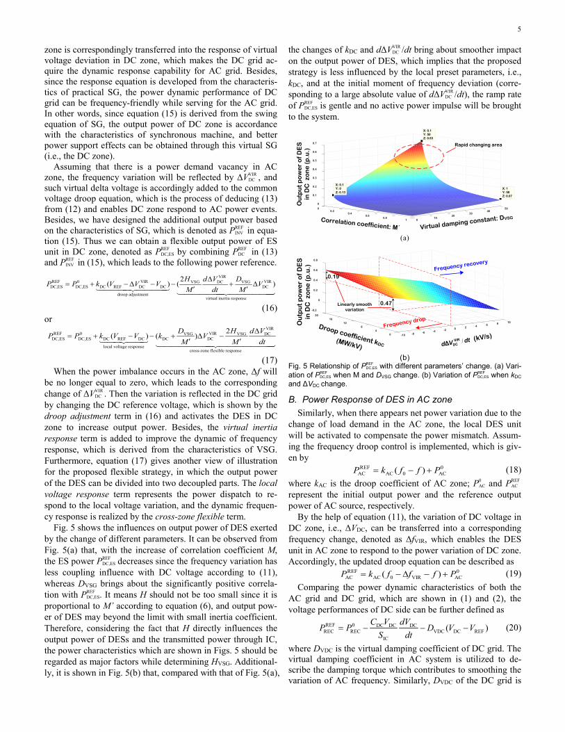
Fig. 5 shows the influences on output power of DES exerted by the change of different parameters. It can be observed from Fig. 5(a) that, with the increase of correlation coefficient M, the ES power PREF
DC,ES decreases since the frequency variation has less coupling influence with DC voltage according to (11), whereas DVSG brings about the significantly positive correla-tion with PREF
DC,ES. It means H should not be too small since it is proportional to M’ according to equation (6), and output pow-er of DES may beyond the limit with small inertia coefficient. Therefore, considering the fact that H directly influences the output power of DESs and the transmitted power through IC, the power characteristics which are shown in Figs. 5 should be regarded as major factors while determining HVSG. Additional-ly, it is shown in Fig. 5(b) that, compared with that of Fig. 5(a),
the changes of kDC and dΔVVIR DC /dt bring about smoother impact
on the output power of DES, which implies that the proposed strategy is less influenced by the local preset parameters, i.e., kDC, and at the initial moment of frequency deviation (corre-sponding to a large absolute value of dΔVVIR
DC /dt), the ramp rate of PREF
DC,ES is gentle and no active power impulse will be brought to the system.
Correlation coefficient: M´ Virtual damping constant: DVSG
0
0.1
0
0.2
50
0.3
0.4
0.5
0.6
0.2 40
0.7
0.4 300.6 20
0.8 101 0
Ou
tpu
t p
ow
er
of
DE
S
in D
C z
on
e (
p.u
.)
X: 0.1 Y: 50
Z: 0.63
X: 0.1 Y: 0
Z: 0.13X: 1
Y: 50 Z: 0.07
Rapid changing area
(a)
-0.2
20
0
0.2
16
0.4
0.6
1012 8
0.8
648 20-24 -4-6-80 -10
Ou
tpu
t p
ow
er
of
DE
S
in D
C z
on
e (
p.u
.)
Droop coefficient kDC (MW/kV)
Frequency drop
Frequency recovery
0.47
0.19
Linearly smooth variation
/VIRDCΔ
d V dt (kV/s)
(b)
Fig. 5 Relationship of PREF DC,ES with different parameters’ change. (a) Vari-
ation of PREF DC,ES when M and DVSG change. (b) Variation of PREF
DC,ES when kDC and ΔVDC change.
B. Power Response of DES in AC zone Similarly, when there appears net power variation due to the
change of load demand in the AC zone, the local DES unit will be activated to compensate the power mismatch. Assum-ing the frequency droop control is implemented, which is giv-en by
REF 0AC AC 0 AC( )= − +P k f f P (18)
where kAC is the droop coefficient of AC zone; P0 AC and PREF
AC represent the initial output power and the reference output power of AC source, respectively.
By the help of equation (11), the variation of DC voltage in DC zone, i.e., ΔVDC, can be transferred into a corresponding frequency change, denoted as ΔfVIR, which enables the DES unit in AC zone to respond to the power variation of DC zone. Accordingly, the updated droop equation can be described as
REF 0AC AC 0 VIR AC( )= − ∆ − +P k f f f P (19)
Comparing the power dynamic characteristics of both the AC grid and DC grid, which are shown in (1) and (2), the voltage performances of DC side can be further defined as
REF 0 DC DC DCREC REC VDC DC REF
IC
( )= − − −C V dV
P P D V VS dt
(20)
where DVDC is the virtual damping coefficient of DC grid. The virtual damping coefficient in AC system is utilized to de-scribe the damping torque which contributes to smoothing the variation of AC frequency. Similarly, DVDC of the DC grid is

6
introduced here to describe the effect of damping the variation of DC voltage.
Substituting the coupling relationship of f and VDC into equation (20) leads to
20 REFDC 0 VIR
REC REC VDC VIRIC
M C f d fP P D M f
S dt′ ∆ ′= − − ∆ (21)
Equation (21) helps the DES unit in AC zone acquire the dynamic response ability for DC zone. Additionally, since the response equation is derived from the characteristics of the real capacitor, the power dynamic performance of AC grid can be voltage-friendly while supporting DC grid.
Combining equations (19) and (21), one can obtain REF 0 2 VIR
AC,ES AC,ES AC 0 VIR VIR 0 VDC VIR
droop adjustmentvirtual capacitance response
( ) ( )d f
P P k f f f C M f D M fdt∆′ ′= + − ∆ − − + ∆
(22) or
REF 0 2 VIRAC,ES AC,ES AC 0 AC VDC VIR VIR 0
local frequency responsecross-zone flexible response
( ) ( )d f
P P k f f k D M f C M fdt∆′ ′= + − − + ∆ −
(23) When the power imbalance occurs in the DC zone, ΔVDC
will be no longer equal to zero, which leads to the correspond-ing change of ΔfVIR. Then the variation is reflected in the AC grid by changing the reference frequency, which is shown by the droop adjustment term in (22) and activates the DES in AC zone to change output power. Besides, the virtual inertia response term is added to improve the dynamic of voltage response which is derived from the operating characteristics of capacitor.
Fig. 6 shows the influences on output power of DES exerted by the change of different parameters. It can be observed from Fig. 6(a) that, with the increase of correlation coefficient M, the ES power PREF
AC,ES increases since the DC voltage variation has more coupling influence with frequency according to (11), which is inverse of that in equation (16) and Fig. 5 (a). And DVDC also brings about the positive correlation with PREF
AC,ES. Furthermore, it is shown in Fig. 6(b) that, the changes of
kAC and dΔfVIR/dt exert smooth impact on PREF AC,ES, which implies
that, for the AC zone, the proposed strategy is the same less influenced by the local preset parameters, i.e., kAC. Besides, with a wide range of dΔfVIR/dt (e.g., from 0 to -10 Hz/s), the output power of ES, i.e., PREF
AC,ES, is varying with a smooth linear track, thus no active power impulse will be brought to the sys-tem.
0 50
0.1
0.2 40
0.2
0.4 30
0.3
0.6 20
0.4
0.8 10
0.5
1 0
Out
put p
ower
of D
ES
in A
C z
one
(p.u
.)
Correlation coefficient: M´ Virtual damping constant: DVDC
X: 0.1 Y: 0
Z: 0.07
X: 1 Y: 50
Z: 0.46
X: 0.1 Y: 50
Z: 0.11
X: 1Y: 0
Z: 0.11
(a)
10
0
20
0.1
0.2
0.3
6
0.4
0.5
16 212 -28 -64 -100
Out
put p
ower
of D
ES
in A
C z
one
(p.u
.)
Droop coefficient kAC (MW/Hz) dΔfVIR/dt (Hz/s)
Voltage drop
Voltage recovery
(b)
Fig. 6 Relationship of PREF AC,ES with different parameters’ change. (a) Vari-
ation of PREF AC,ES when M’ and DVDC change. (b) Variation of PREF
AC,ES when kAC and ΔfVIR change.
C. Cross-zone Power Compensation with IC From the discussion above, we can see that when there oc-
curs the net power deficiency in DC side, the DES unit in AC side can obtain the power reference to transfer to DC side, and contribute to DC voltage stability. Therefore, the DC voltage is supported by DESs in both AC and DC sides, which will significantly improve the voltage dynamic performance. Simi-larly, when there occurs the net power deficiency in AC side, the DES unit in DC side can possess the power reference to transfer to AC side, and contribute to AC frequency. Thus, the frequency dynamics of AC sub-grid can be enhanced com-pared with the situation in which only one-side DES is acti-vated.
With the power demands appearing in both zones, there may be clash among control signals. In other words, both zones will be requiring power support from the opposite zone and the power transmitted through ICs should be properly determined, or the power transferred to the opposite zone may oscillate or fluctuate during the cross-zone support, since the frequency and voltage in both zones are not stable in the tran-sient process. To avoid this situation and transmit the flexible support power of DESs in different zones, the reference power of IC between the DC and AC zones are defined in (24), as the difference of the flexible terms from equations (17) and (23), which can reduce the possible power oscillation during the mutual power support.
REF REF REF REF REFIC AC,ES AC DC,ES DC( ) ( )P P P P P= − − − (24)
It is worth noting that equation (24) is obtained by finding the difference of the flexible terms of equations (16) and (22), and the process and more essentially detailed expression is given as follows.
REF VIRVSGIC DC DC AC VDC VIR
VIR2VSG DC VIR
VIR 0
=( ) ( )
2
DP k V k D M f
MH d V d f
C M fM dt dt
′+ ∆ − + ∆′∆ ∆′+ −
′
(25)
It can be seen from the above equation that, the IC reference power can be calculated from the virtual AC frequency and DC voltage variation. Since ΔfVIR and ΔVVIR
DC are derived from the real frequency and voltage change according to equation (11), the IC power can be conveniently obtained by collecting and processing frequency and DC voltage values of IC’s con-

7
necting points at both DC and AC sides. Therefore, there is no need to know the real-time active power of every DESs’ con-verters.
Therefore, the proposed strategy does not need central con-troller, which features high reliability and response speed. More specifically, the proposed method is based on the im-proved droop principle, and the IC and DES need only signals of frequency and DC voltage. Then, the value of power refer-ence can be obtained by the local controller embedded in DESs and IC, of which the process is free of high-bandwidth communication and feasible to be implemented in practice.
Fig. 7 gives the illustration of four different power states of IC, in which the response power of DESs in DC and AC zones are also depicted respectively with blue and purple surfaces. Besides, the relationship between virtual variable changes (i.e., ΔfVIR and ΔVVIR
DC ) and the corresponding voltage and frequency variation are clearly shown at the ground coordinate. Assum-ing the power flowing from AC side to DC side is positive, the operational states are discussed in detail as follows:
1) State I: In this state, ΔVVIR DC >0, ΔfVIR<0, which indicates that
the power generation is beyond the power demand in AC zone and there appears net power vacancy in DC zone. Therefore, there are surplus power supply in AC zone rais-ing the frequency and the power deficiency in DC zone de-teriorating the voltage, and the power flow of IC is sup-posed to be transferred from AC side to DC side, which can properly dispatch and utilize the redundant power.
2) State II: In this state, ΔVVIR DC <0, ΔfVIR<0, which indicates that
there is net power deficiency in both the AC zone and DC zone and the additional power demands are required in both sides. Therefore, on the premise of ensuring local power quality, the direction of IC power is determined according to (24) and is not always unified in this situation, which means the supportive power will be shared accordingly to improve the global power quality of both zones. It should be noted that, the IC will be blocked when there is a risk that the power quality is down below the normal variation threshold in both zones (determined by the operator), and the emergency measures such as load shedding are sup-posed to be taken.
3) State III: In this state, ΔVVIR DC <0, ΔfVIR>0, which indicates
that the power generation is beyond the power demand in DC zone and there appears net power vacancy in AC zone. Therefore, there are surplus power supply in DC zone rais-ing the voltage and the power deficiency in AC zone deteri-orating the frequency, and the power flow of IC is supposed to be transferred from DC side to AC side.
4) State IV: In this state, ΔVVIR DC >0, ΔfVIR>0, which indicates
that there appears power generation surplus in both zones. The generation units in SPS will reduce the output power in this situation. Besides, by accordingly changing the power flow and activating the DESs of the whole system, the pro-posed strategy can provide another power balancing channel and help the absorption of excessive power generation.
-0.6-1.5
-0.4
-1
-0.2
-1
0
-0.5
0.2
-0.5
0.4
0.6
000.50.5 1
1.51
REF
IC (p
.u.)
P
VIRDC
Δ (kV) V
VIRΔ (Hz) f
Frequency dropVoltage increaseFrequency increase
DES response in DC zone
Voltage drop
III
III
IV
DES response in AC zone
Fig. 7 Reference power of IC in different situations.
It is worth noting that, during long-term operation, the DESs in SPS will be charged to keep its reasonable state of charge (SoC) level when the SPS is working in the stable con-dition and no impulse power demand is expected. Besides, since the power variation is shared by all the DESs in hybrid zones, the proposed strategy can indirectly contribute to main-taining the balance of SoC.
D. Design of the Flexible Power Control Loop The proposed power control strategy is realized through the
coordination of the IC and the DESs in hybrid zones, as shown in Fig. 8. By collecting the variation of local electrical variable (i.e., VDC of DC zone and f of AC zone), the ES unit can re-spond to the local power variation according the preset droop coefficient. Besides, the change of local electrical variable will be transferred to the opposite zone according to (17) and (23), so that an inter-zone flexible response is realized by generat-ing the additional power signal to the ES controller in the op-posite zone. The difference between PREF
INV and PREF REC is set as the
power reference of IC, which can reduce the possible power fluctuation during operation. The detailed feature analysis with different parameters (e.g., Figs. 5 and 6 and relevant con-tents) can serve for the guidance of parameter determination. Based on the visualized analysis in the previous section, we can choose the reasonable values of the parameters when em-ploy the strategy in practice.
Fig. 9 shows the detailed design of the dual loop controllers based on Fig. 8. It can be seen that, the controllers for DESs and IC are developed from the common control structure of converters [27], [28], which means the controllers are easily incorporated into the engineering application. Besides, the hysteresis controller is adopted to avoid the frequent activation of the converter when the DC voltage or frequency changes near the boundaries of dead band, which is utilized well in engineering practice and can protect the DES unit during the cross-zone power compensation. More specifically, when the frequency or voltage variation is less than the specific thresh-old, the proposed strategy should have no response and there may be no power support from the ES unit, which can prevent activation caused by interfering signals and small power dis-turbances. It should be noted that, the threshold is usually set as a small value and will not influence the effectiveness of the strategy.

8
Local voltage responseOuter control loop
-
+fACk−
′ + +DC VSG VSG2k M H s D
-
+
+
−′ ′+ +1AC 0 VIR VDCk M M f C s D
0f
VREF
VDC
P 0INV
-
P 0REC
+
-
+
-
P REFAC,ES
P REFDC,ES
P REFIC
ES-inverter in AC zone
IC
ES-converter in DC zone
Outer control loop
Inter-zone flexible response
Local frequency response+
+
+
+
REFINVP ′
REFRECP ′
DCk−
Fig. 8 Control scheme of the proposed strategy
V. CASE STUDIES In order to validate the proposed flexible power control
strategy, a comprehensive SPS model with hybrid AC/DC zones is developed based on Fig. 1 in the environment of DISILENT/PowerFactory. For convenience, in each zone, distributed generators (DGs) are substituted using a controlla-ble aggregating generator to reasonably simplify the simula-tion model, since the inner characteristics of these power sup-pliers play no significant role in the following simulation and we focus on the characteristics of net power variation rather than that of different power sources. All the DGs except for DESs in hybrid system are operating with conventional droop operation mode to guarantee the dynamic performance are just influenced by the response of DESs and IC, and the global power balance shall still be established with the contribution of all power generations, as shown in the simulation results. The parameters of the simulation model are listed in Table I [5], [24], [29]. In order to obtain a good control performance, the controller parameters (e.g., HVSG, CDC, DVSG, DVDC) are designed according to the characteristics analysis in Sec. III.
TABLE I KEY PARAMETERS OF THE STUDIED SPS WITH HYBRID ZONES
Sub-systems Items Values IC Rated power: SIC /MVA 15
AC zone
Nominal frequency: f0/Hz 50 Droop coefficient: kAC /(MW/Hz) 17.3 Virtual inertial constant: HVSG/s 6.5×10⁻³
Virtual damping coefficient: DVSG 20 Rated power of DES unit/MW 10
DC zone Nominal voltage: VREF /kV 7
Droop coefficient: kDC /(MW/kV) 15.8
DC capacitor: CDC /mF 7.5 Virtual damping coefficient: DVDC 20
Rated power of DES unit/MW 10
The energy storage used in the simulations is a Li-ion bat-tery, since it presents a good balance between energy density and fast power response [30]. Besides, the size of the ES is set as 0.5 MWh, which can meet the power requirements in simu-lation cases. It is worth noting that the type and size of ES device will not influence the effectiveness of the proposed strategy as long as the ES can provide enough energy capacity and power response speed.
In the simulation cases, three different scenarios are com-pared together: the proposed flexible power support strategy, only-droop strategy and no support strategy. For better illus-tration, the respective definition and features are listed as bel-low:
1) No support strategy. In this strategy, the IC is blocked and will not transfer any power between hybrid sides, so the two sides are islanded from each other. Since the DC and AC side should only be responsible for local power variation in this situation, the voltage and frequency quality would be the worst when local net power changes, and nearly have no fluc-tuation when the power disturbance occurs in the other side. Therefore, the key parameters used in this strategy are the respective local droop coefficients described in equations (12) and (18), which are kDC and kAC.
2) Proposed flexible strategy. In this strategy, the IC is uti-lized flexibly for power sharing between AC and DC sides, transferring active power according to the proposed equations. In this situation, not only the local droop response will be ac-tivated (i.e., the conventional droop control for local power disturbance), but also the mutual power support between zones will be employed [i.e., the cross-zone flexible power response defined in equations (17) and (23)]. Thus, the hybrid sides are connected with each other, and the power of DESs in two sides can be dispatched for the opposite sides. Therefore, the key parameters used in this strategy include kDC, kAC, HVSG, CDC, DVSG and DVDC.
3) Only droop strategy. In this strategy, the voltage and fre-quency variation can be mutually transformed according to the sampling period time constant, and thus the virtual frequency and virtual voltage changes are obtained. Then, adding the
Q: reactive power : reference current of d-axisQREF: reference reactive power : reference current of q-axisiES: output current of ES unit
dqabc
PI
PI
PWM
PI
PI
f0
VES
Equation(22)
1/VES
iES
0AC,ESP
iES
f
VSC
AC bus
ICAC/DC
VDC
Δf
hysteresis controller
Modulating signal in d_q frame
Inner controller
Outer controller
Filter
Reactor
REFAC,ESP
ES unit
AC Zone
QREFQ -
-
REFdiREFqi
dqabc
Q- PI
PIPI
PWM
Equation(24)
PI
f VDC
Outer controller
Outer controller
Inner controller
Modulating signal
AC/DC Interface
Filter
ReactorTransformer
-ΔfVIR
VREF
M-1
VDC -From DC bus
DC bus
iES
VES
hysteresis controller
Equation(17)
1/VES
iESREF
ESPPI
PWM
DC/DC ΔVDC
ES unit
-
-
VDC
VREF
f0
-M
fFrom AC bus
Inner controller
Outer controller
DC Zone
Modulating signal REF
AC,ESi
QREF
REFqi
REFdi
REFdi
VDC
0DC,ESP
VIRDCV∆
REFESP
REFESi
REFESi
: reference active power of ES unit : reference current of ES unit
Low pass filter
Low pass filter
REFqi
Fig. 9 Controller configuration of the proposed strategy for DESs and IC
9
virtual terms to the conventional droop equations and so-called “ac-dc droop” method, which is defined as only droop strategy, can be obtained. This method is well accepted for the coordinated control of hybrid AC/DC microgrids and can be found in [18]. Compared with the proposed strategy, this mu-tual transformation of AC frequency and DC voltage has no clear physical meaning. Besides, the key parameters of the strategy are kDC and kAC, which makes it less adjustable when determining power reference.
As can be seen from the illustration above that, the pro-posed strategy has the additional parts concerning the physical operational characteristics, i.e. inertia, capacitance and damp-ing effects, which enable our strategy to provide more flexible power support ability. Therefore, in the simulation cases, the parameters kDC and kAC, used in all three methods will be set as the same value for each strategy for fairness. As for the parameters utilized only in the proposed strategy, we will de-termine their values according to the theoretical analysis.
In the simulation cases of this paper, the normal variation range of power quality in this paper are defined as ±0.5% of frequency (±0.25 Hz) for AC zone and ±5% of voltage (±0.35kV) for DC zone. In order to reflect overall variation and stability level of the hybrid system, a global variation in-dex is defined here and described as,
DC
max min max min
∆∆= +
− −viVfG
f f V V (26)
where fmax and Vmax are the maximum value of the normal var-iation of f and VDC, respectively; fmin and Vmin are the minimum value of the normal variation, respectively.
The global variation index is essentially the normalization of the variation of both frequency and DC voltage. The more this index approaches to zero, the more stable the whole sys-tem is, which can be used to directly reflect the stability level of the hybrid grid.
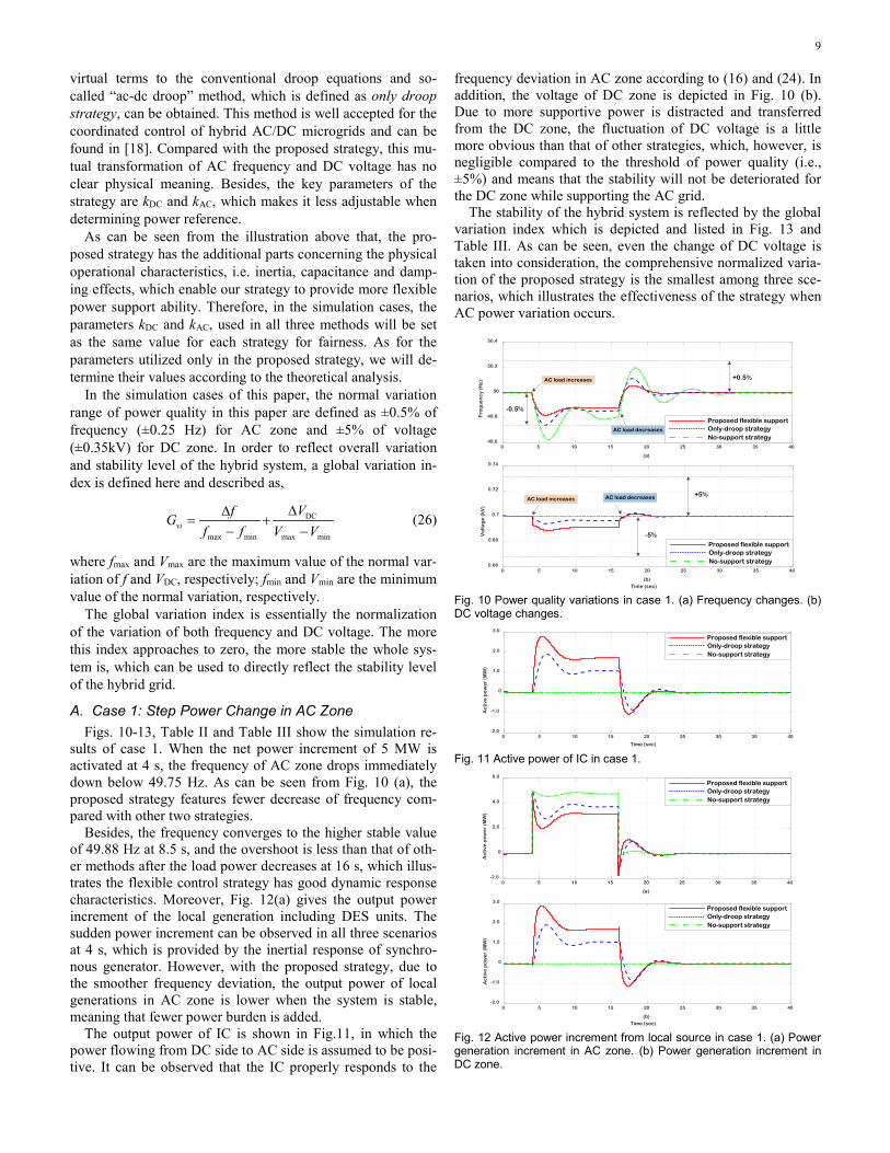
A. Case 1: Step Power Change in AC Zone Figs. 10-13, Table II and Table III show the simulation re-
sults of case 1. When the net power increment of 5 MW is activated at 4 s, the frequency of AC zone drops immediately down below 49.75 Hz. As can be seen from Fig. 10 (a), the proposed strategy features fewer decrease of frequency com-pared with other two strategies.
Besides, the frequency converges to the higher stable value of 49.88 Hz at 8.5 s, and the overshoot is less than that of oth-er methods after the load power decreases at 16 s, which illus-trates the flexible control strategy has good dynamic response characteristics. Moreover, Fig. 12(a) gives the output power increment of the local generation including DES units. The sudden power increment can be observed in all three scenarios at 4 s, which is provided by the inertial response of synchro-nous generator. However, with the proposed strategy, due to the smoother frequency deviation, the output power of local generations in AC zone is lower when the system is stable, meaning that fewer power burden is added.
The output power of IC is shown in Fig.11, in which the power flowing from DC side to AC side is assumed to be posi-tive. It can be observed that the IC properly responds to the
frequency deviation in AC zone according to (16) and (24). In addition, the voltage of DC zone is depicted in Fig. 10 (b). Due to more supportive power is distracted and transferred from the DC zone, the fluctuation of DC voltage is a little more obvious than that of other strategies, which, however, is negligible compared to the threshold of power quality (i.e., ±5%) and means that the stability will not be deteriorated for the DC zone while supporting the AC grid.
The stability of the hybrid system is reflected by the global variation index which is depicted and listed in Fig. 13 and Table III. As can be seen, even the change of DC voltage is taken into consideration, the comprehensive normalized varia-tion of the proposed strategy is the smallest among three sce-narios, which illustrates the effectiveness of the strategy when AC power variation occurs.
0 5 10 15 20 25 30 35 40
(a)
49.6
49.8
50
50.2
50.4
Fre
qu
en
cy
(Hz)
+0.5%
-0.5%
Proposed flexible supportOnly-droop strategyNo-support strategy
AC load increases
AC load decreases
0 5 10 15 20 25 30 35 40
(b)Time (sec)
0.66
0.68
0.7
0.72
0.74
Vo
lta
ge
(kV
)
+5%AC load increases AC load decreases
-5%
Proposed flexible supportOnly-droop strategyNo-support strategy
Fig. 10 Power quality variations in case 1. (a) Frequency changes. (b) DC voltage changes.
0 5 10 15 20 25 30 35 40
Time (sec)
-2.0
-1.0
0
1.0
2.0
3.0
Ac
tive
po
we
r (M
W)
Proposed flexible supportOnly-droop strategyNo-support strategy
Fig. 11 Active power of IC in case 1.
0 5 10 15 20 25 30 35 40
(a)
-2.0
0
2.0
4.0
6.0
Ac
tive
po
we
r (M
W)
Proposed flexible supportOnly-droop strategyNo-support strategy
0 5 10 15 20 25 30 35 40
(b)Time (sec)
-2.0
-1.0
0
1.0
2.0
3.0
Ac
tive
po
we
r (M
W)
Proposed flexible supportOnly-droop strategyNo-support strategy
Fig. 12 Active power increment from local source in case 1. (a) Power generation increment in AC zone. (b) Power generation increment in DC zone.

10
0 5 10 15 20 25 30 35 40
Time (sec)
-1.0
-0.5
0
0.5
1.0
Glo
ba
l va
ria
tio
n in
de
x
Proposed flexible supportOnly-droop strategyNo-support strategy
Fig. 13 Global variation index in case 1.
TABLE II EXTREMA OF THE FREQUENCY AND DC VOLTAGE OF SPS (CASE 1)
Variable Scenario 0-4 s 4-16 s 16-40 s
Frequency (Hz) Proposed support 50 49.82 50.05
Only-droop strategy 50 49.74 50.12 No-support strategy 50 49.62 50.19
DC voltage (kV) Proposed support 7 6.88 7.01
Only-droop strategy 7 6.94 7.02 No-support strategy 7 7 7
TABLE III Extrema of Global Variation Index (Case 1)
Scenario 0-4 s 4-16 s 16-40 s Proposed support 0 -0.46 0.14
Only-droop strategy 0 -0.59 0.26 No-support strategy 0 -0.74 0.41
B. Case 2: Step Power Change in DC Zone Figs. 14-17, Table IV and Table V show the simulation re-
sults of case 2. Due to the lack of rotational inertia in DC zone, there occurs a sudden drop of DC voltage when the net power increment of 5 MW is activated at 4s, as shown in Fig. 14 (a). However, with the proposed flexible strategy, the fluctuation of DC voltage is mitigated since the dynamic response charac-teristics of the strategy (more and quicker power transferred shown in Fig. 15) help to gain more response time for the local DC sources.
With the proposed strategy, the DC voltage decreases with a mild trend and reaches the lowest point of 6.87 kV, then the voltage stabilizes at the value of 6.89 kV at t=10s. In compari-son, the DC voltage in other two scenarios drops directly from reference value to 6.81 kV and 6.75 kV, respectively. It can be seen that the only-droop strategy provides higher stable point, but also makes the system suffer the sudden impulse of volt-age variation, which brings about negative effect on system stability and might shorten the life span of equipment in DC zone. When the load power decrease is activated at 16s, the voltage recovers to 7 kV, and the proposed method offers a smoother transient process with little overshoot. Therefore, we can conclude that the flexible strategy significantly improves the voltage quality when the power variation occurs in DC zone. Besides, the power burden of DGs including DES in DC zone is relieved compared with that of other two scenarios, as shown in Fig. 16(a).
As can be seen from Figs. 15-16, the better performance of the strategy benefits from the quick power transfer of IC from AC zone to DC zone, and the power burden is properly shared by both zones, which exploits the power support ability of the DESs in the whole system. Besides, the fluctuation of fre-quency is mild and can even be negligible, ranging from 49.90 to 50.03 Hz, which means the frequency quality, correspond-ing to the stability for AC zone, is little influenced. Therefore, the proposed strategy helps improving the robust characteris-tics from the regard of the whole SPS system.
The global variation index is depicted and listed in Fig. 17 and Table V. As can be seen, even the change of frequency is taken into consideration, the comprehensive normalized varia-tion of the proposed strategy is the smallest among three sce-narios (the little larger overshoot during power decrease is of the negligible magnitude), which illustrates the effectiveness of the strategy when DC power variation occurs.
0 5 10 15 20 25 30 35 40
(b)Time (sec)
49.6
49.8
50
50.2
50.4
Fre
qu
en
cy
(Hz)
0 5 10 15 20 25 30 35 40
(a)
6.6
6.8
7.0
7.2
7.4
Vo
lta
ge
(kV
)
+5%
-5%
DC load increasesDC load decreases
+0.5%
-0.5%
Proposed flexible supportOnly-droop strategyNo-support strategy
Proposed flexible supportOnly-droop strategyNo-support strategy
Fig. 14 Power quality variations in case 2. (a) DC voltage changes. (b) Frequency changes.
0 5 10 15 20 25 30 35 40
Time (sec)
-3.0
-2.0
-1.0
0
1.0
2.0A
cti
ve p
ow
er
(MW
)
Proposed flexible supportOnly-droop strategyNo-support strategy
Fig. 15 Active power of IC in case 2.
0 5 10 15 20 25 30 35 40
(a)
-2.0
0
2.0
4.0
6.0
Ac
tive
po
we
r (M
W)
Proposed flexible supportOnly-droop strategyNo-support strategy
0 5 10 15 20 25 30 35 40
(b)Time (sec)
-2.0
-1.0
0
1.0
2.0
3.0
Ac
tive
po
we
r (M
W)
Proposed flexible supportOnly-droop strategyNo-support strategy
Fig. 16 Active power increment from local source in case 2. (a) Power generation increment in DC zone. (b) Power generation increment in AC zone.
0 5 10 15 20 25 30 35 40
Time (sec)
-1.0
-0.5
0
0.5
1.0
Glo
ba
l va
ria
tio
n in
de
x
Proposed flexible supportOnly-droop strategyNo-support strategy
Fig. 17 Global variation index in case 2.

11
TABLE IV EXTREMA OF THE FREQUENCY AND DC VOLTAGE OF SPS (CASE 2)
Variable Scenario 0-4 s 4-16 s 16-40 s
Frequency (Hz) Proposed support 50 49.91 50.04
Only-droop strategy 50 49.95 50.02 No-support strategy 50 50 50
DC voltage (kV) Proposed support 7 6.89 7.02
Only-droop strategy 7 6.82 7.01 No-support strategy 7 6.76 7.01
TABLE V
EXTREMA OF GLOBAL VARIATION INDEX (CASE 2) Scenario 0-4 s 4-16 s 16-40 s
Proposed support 0 -0.24 0.041 Only-droop strategy 0 -0.32 0.039 No-support strategy 0 -0.34 0.020
C. Case 3: Consecutive Power Changes in AC&DC Zones
Figs. 18-21, Table VI and Table VII show the simulation results of case 3. A series of net power events in hybrid zones are activated in this simulation case. As can be seen in Fig. 18, the power quality (i.e., the variation of frequency and DC voltage) of the hybrid zones when power disturbances occur has been significantly improved with the help of the proposed strategy.
During 4-10 s, the net power increment of 4.5 MW is adopted in DC zone and causes a voltage drop accordingly. The flexible strategy effectively slows down the variation trend of DC voltage, shown in Fig. 18(b), which leaves larger drop margin for the next power variation. During 10-22 s, the net power increment of 5 MW is activated in AC zone and causes a frequency drop accordingly. As shown in Fig. 18(a), though the frequency curve with the flexible strategy is lower at the beginning of 10 s, it reaches to the higher lowest point of 49.78 Hz, and converges to stable value more quickly and thus has better transient response. By comparison, the fre-quency of other scenarios both drop under the normal varia-tion range, and some emergency measures might be taken to keep the system’s stability. In addition, the DC voltage is also showing higher stable value with 6.84 kV compared with oth-er two scenarios.
The power increments are canceled at 22 s in DC zone and at 32 s in AC zone, respectively. During the recovery process, smoother variations of frequency and voltage can be observed from Fig. 20, which illustrates the good performance of the strategy under the de-loading situation. It is worth noting that, the performance under continuous power variation might have no such significant improvement in stable value compared with that when power disturbance occurs in only single zone, but the transient performance improvement is still clear and contributes to the system robustness.
It can be observed from Fig. 20 that, the better performance is realized by the reasonable power sharing between the hybrid zones and our strategy does not require more power supply from local generations, meaning that no extra power burden is caused with the proposed method, which features high effi-ciency during operation.
The global variation index is depicted and listed in Fig. 21 and Table VII. As can be seen, when the consecutive power variations occur in both AC and DC zones, the comprehensive
normalized variation of the proposed strategy is the smallest among three scenarios, which illustrates the effectiveness of the strategy under complex operational situations.
0 5 10 15 20 25 30 35 40
(b)Time (sec)
6.6
6.8
7.0
7.2
7.4
Ac
tive
po
we
r (k
V)
0 5 10 15 20 25 30 35 40
(a)
49.6
49.8
50
50.2
50.4
Fre
qu
en
cy
(Hz)
Proposed flexible supportOnly-droop strategyNo-support strategy
-0.5%
+0.5%DC load increases
AC load increases
DC load decreasesAC load decreases
+5%
-5%
Proposed flexible supportOnly-droop strategyNo-support strategy
DC load increases
AC load increases
DC load decreases
AC load decreases
Fig. 18 Power quality variations in case 3. (a) Frequency changes. (b) DC voltage changes.
0 5 10 15 20 25 30 35 40
Time (sec)
-6.0
-4.0
-2.
0
2.0
4.0
6.0
Ac
tive
po
we
r (M
W)
Proposed flexible supportOnly-droop strategyNo-support strategy
Fig. 19 Active power of IC in case 3.
0 5 10 15 20 25 30 35 40
(a)
-2.0
0
2.0
4.0
6.0
8.0
Ac
tive
po
we
r (M
W)
Proposed flexible supportOnly-droop strategyNo-support strategy
0 5 10 15 20 25 30 35 40
(b)Time (sec)
-2.0
0
2.0
4.0
6.0
8.0
Ac
tive
po
we
r (M
W)
Proposed flexible supportOnly-droop strategyNo-support strategy
Fig. 20 Active power increment from local sources in case 3. (a) Power generation increment in DC zone. (b) Power generation increment in AC zone.
0 5 10 15 20 25 30 35 40
Time (sec)
-1.5
-1.0
-0.5
0
0.5
1.0
Glo
ba
l va
ria
tio
n in
de
x
Proposed flexible supportOnly-droop strategyNo-support strategy
Fig. 21 Global variation index in case 3.

12
TABLE VI EXTREMA OF THE FREQUENCY AND DC VOLTAGE OF SPS (CASE 3)
Variable Scenario 4-10s 10-22s 22-32s 32-40s
Frequency (Hz)
Proposed support 49.95 49.79 49.89 50.05
Only-droop strategy 49.98 49.71 49.85 50.11
No-support strategy 50 49.63 49.82 50.18
DC voltage (kV)
Proposed support 6.89 6.82 6.95 7.01
Only-droop strategy 6.84 6.78 6.96 7.01
No-support strategy 6.76 6.76 7.01 7
TABLE VII
EXTREMA OF GLOBAL VARIATION INDEX (CASE 3) Scenario 4-10s 10-22s 22-32s 32-40s
Proposed support -0.24 -0.69 -0.26 0.14 Only-droop strategy -0.32 -0.85 -0.30 0.26 No-support strategy -0.34 -1.08 -0.35 0.38
VI. CONCLUSION In this paper, a flexible power control strategy for hybrid
SPS system is proposed, which fully considers global power support capability of DESs in different zones. The proposed strategy sufficiently utilizes the operational features of both the AC and DC grids, and shows good performances in dimin-ishing the variation of frequency and DC voltage during se-vere power events. Key findings of this paper can be summa-rized as: 1) The relationship between the frequency and the DC voltage is discussed based on the principles of VSG and virtual capacitor, which is used to design the flexible power strategy for the DESs and ICs of the hybrid zones in SPS; 2) The proposed strategy is designed according to the operating characteristics of the hybrid system, which enables the DES units to respond to the net power deviation of both the local and the opposite zones, and by the help of ICs between the hybrid grids, a reasonable mutual power support is realized to enhance the power quality and dynamics of the whole SPS while facing short-term high power demand.
In the future works, a multi-level power control strategy will be extended from this study for multiple time scale opti-mization of SPS’s performance, in which the operational fea-tures of variable generations will be considered and hybrid energy storage system will be considered.
VII. REFERENCES [1] B. Stevens, A. Dubey and S. Santoso, “On improving reliability of ship-
board power system,” IEEE Trans. Power syst., vol. 30, no. 4, pp.1905-1912, Jul. 2015.
[2] F. Wang, Z. Zhang and T. Ericsen, “Advances in power conversion and drives for shipboard systems,” Proc. IEEE Electr. Ship Technol. Symp., vol. 103, no. 12, pp. 2285-2311, Dec. 2015.
[3] M. Cupelli, F. Ponci, G. Sulligoi, A. Vicenzutti, C. S. Edrington, et al. “Power flow control and network stability in an all-electric ship,” Proc. IEEE, vol. 103, no. 12, pp. 2355–2380, Dec. 2015.
[4] G. J. Tsekouras, F. D. Kanellos and J. Prousalidis, “Simplified method for the assessment of ship electric power systems operation cost reduction from energy storage and renewable energy sources integration,” IET Elect. Syst. Transp., vol. 5, no. 2, pp. 61-69, Jun. 2015.
[5] R. E. Hebner, F. M. Uriarte, A. Kwasinski, et al., “Technical cross-fertilization between terrestrial microgrids and ship power systems,” J. Modern Power Syst. Clean Energy, vol. 4, no. 2, pp. 161–179, May 2015.
[6] Z. Jin, G. Sulligoi, R. Cuzner, L. Meng, J. C. Vasquez, and J. M. Guerre-ro, “Next-generation shipboard DC power system: introduction smart grid and dc microgrid technologies into maritime electrical networks,” IEEE Electrific. Mag., vol. 4, no. 2, pp. 45–57, Jun. 2016.
[7] M. Banaei and R. Alizadeh, “Simulation-based modeling and power management of all-electric ships based on renewable energy generation using model predictive control strategy,” IEEE Intell. Transp. Syst. Mag., vol. 8, no. 2, pp. 90-103, Jul. 2016.
[8] N. Doerry, Next Generation Integrated Power System NGIPS Technolo-gy Development Roadmap, Naval Sea System Command, Nov. 2007.
[9] X. Feng, K. L. Butler-Purry and T. Zourntos, “A multi-agent system framework for real-time electric load management in MVAC all-electric ship power systems,” IEEE Trans. Power Syst., vol. 30, no. 3, pp. 1327-1336, May 2015.
[10] D. Tang, X. Yan, Y. Yuan, et al., “Multi-agent based power and energy management system for hybrid ships,” in Proc. Int. Conf. Renewable Energy Res. Appl., pp. 383-387, 2016.
[11] F. D. Kanellos, G. J. Tsekouras, and N. D. Hatziargyriou, “Optimal de-mand-side management and power generation scheduling in an all-electric ship,” IEEE Trans. Sustain. Energy, vol. 5, no. 4, pp. 1166-1175, Oct. 2014.
[12] M. M. S. Khan, M. O. Faruque and A. Newaz, “Fuzzy logic based ener-gy storage management system for MVDC power system of all electric ship,” IEEE Trans. Energy Convers., vol. 32, no. 2, pp. 798–809, Jan. 2017.
[13] G. Seenumani, J. Sun, and H. Peng, “A hierarchical optimal control strategy for power management of hybrid power systems in all electric ships applications,” in Proc. IEEE Conf. Decision and Control (CDC), pp. 3972-3977, 2010.
[14] J. Hou, J. Sun and H. F. Hofmann, “Mitigating power fluctuations in electric ship propulsion with hybrid energy storage system: design and analysis,” IEEE J. Oceanic Eng., to be published, DOI: 10.1109/JOE.2017.2674878
[15] T. V. Vu, D. Gonsoulin, F. Diaz et al., “Predictive control for energy management in ship power systems under high-power ramp rate loads,” IEEE Trans. Energy Convers., vol. 32, no. 2, pp. 788–797, Apr. 2017.
[16] R. Wang, L. Chen, T. Zhang and S. Mei, “VSG-based Adaptive Droop Control for Frequency and Active Power Regulation in the MTDC Sys-tem,” CSEE Journal of Power and Energy Systems, vol. 3, no. 3, pp. 260-268, Sept. 2017.
[17] P. C. Loh, D. Li, Y. K. Chai and F. Blaabjerg, “Autonomous operation of hybrid microgrid with AC and DC subgrids,” IEEE Trans. Power Elec-tron., vol. 28, no. 5, pp. 2214–2223, May 2013.
[18] N. Eghtedarpour and E. Farjah, “Power control and management in a hybrid AC/DC microgrid,” IEEE Trans. Smart Grid, vol. 5, no. 3, pp. 1494-1505, May 2014.
[19] F. Nejabatkhah and Y. W. Li, “Overview of power management strate-gies of hybrid AC/DC microgrid,” IEEE Trans. Power Electron., vol. 30, no. 12, pp. 7072–7089, Dec. 2015.
[20] X. Liu, P. Wang and P. C. Loh, “A hybrid AC/DC microgrid and its coordination control,” IEEE Trans. Smart Grid, vol. 2, no. 2, pp. 278-286, Jun. 2011.
[21] V. C. Gungor, D. Sahin, T. Kocak, et al., “A survey on smart grid poten-tial applications and communication requirements,” IEEE Trans. Ind. In-format., vol. 9, no. 1, pp. 28–42, Feb. 2013.
[22] P. García, P. Arboleya, et al., “Implementation of a hybrid distribut-ed/centralized real-time monitoring system for a DC/AC microgrid with energy storage capabilities,” IEEE Trans. Ind. Informat., vol. 12, no. 5, pp. 1900–1909, Oct. 2016.
[23] C. Petry and J. Rumburg, “Zonal electrical distribution systems: An affordable architecture for the future,” Naval Eng. J., vol.105, pp.45-51, May 1993.
[24] IEEE recommended practice for 1kV to 35 kV medium-voltage dc power system on ships, IEEE standard 1709, 2010.
[25] J. Zhu, C. D. Booth, G. P. Adam, A. J. Roscoe and C. G. Bright, “Inertia emulation control strategy for VSC-HVDC transmission systems,” IEEE Trans. Power Syst., vol. 28, no. 2, pp. 1277-1287, May 2013.
[26] P. Kundur, Power systems stability and control. New York, NY, USA: McGraw-Hill, 1993.
[27] A. Agarwal and V. Agarwal, “FPGA Realization of Trapezoidal PWM for Generalized Frequency Converter,” IEEE Trans. Ind. Informat., vol. 8, no. 3, pp. 501–510, Aug. 2012.
[28] W. Guo and L. Mu, “Control principles of micro-source inverters used in microgrid,” Protection and Control of Modern Power Systems, vol.1, no.1, pp.1-7, Dec. 2016.

13
[29] G. Sulligoi, A. Tessarolo, V. Benucci, A. M. Trapani, M. Baret, and F. Luise, “Shipboard power generation, design and development of a me-dium-voltage dc generation system,” IEEE Ind. Appl. Mag., vol. 19, no. 4, pp. 47–55, Jul./Aug. 2013.
[30] J. Xiao, P. Wang, and L. Setyawan, “Multilevel Energy Management System for Hybridization of Energy Storages in DC Microgrids,” IEEE Trans. Smart Grid, vol.7, no.2, pp.847-856, Mar. 2016.