vcap5-dcd study pack by jason grierson -...
TRANSCRIPT
DCD 5.5 Study pack
Created by Jason GriersonChris WilliamsShahed Hasib
Table of Contents
- Risk, Constraints, Assumptions, Requirements, Availability, Performance, Manageability, Recoverability, and Security
- Functional Requirements and Non-Functional Requirements- Conceptual, Logical, Physical Design, working through the phases- Admission Control % vs Slot and Calculation formulas- Admission Control Compute, Sizing, and Calculations- Monster VM’s and NUMA Nodes- Storage Best Practices, Fiber, iSCSI, NFS, PSP(Path Selection Policies)- Resource Pools, Child Pools, and who gets what- NIOC (Shares, Physical Adapter Limits, Shared & Limits Combined)- AutoDeploy- Implementation Steps (Upgrading vCenter, VDS, Migrating Datacenters, Migrating VDS)- vSphere Backup Data Protector- vSphere Replication & SRM- Upstream/Downstream Dependencies
Risk, Constraints, Assumption, Requirements, Availability, Performance, Manageability, Recoverability, and Security
These are all well-known definitions that VMware and the DCD will want you to know and use during customer interactions. You will need to know how to break down a customer’s list of wants / scenario into these categories. A better way of explain this would be to break down the Conceptual Design into these categories.
To do this however you will need a solid understanding of each definition. This is what this section will try to do with a collection of definitions and examples.
Risk Things that might prevent project completion Tasks or items that might prevent achieving project goals
Examples
User commitment Single points of failure Project being delivered on time High risk area’s for outages or natural disasters Not meeting business compliance (ISO, ITIL, etc) Data leaks or unprotected data
Constraints A Nonnegotiable limit on design Business policy or technical limitation that is limiting the design choice
Examples
The project has to be finished in 4 months The total cost must not exceed $200, 000 The IT budget has been set at 20% of revenue The hardware vendor has to be XXX Reuse existing storage
Assumption Assumptions are factors considered to be true without proof in the planning phase Is accepted as true without being tested
A thing that is accepted as true or as certain to happen, without proof.
Examples
Existing power will support new servers Equipment will be available at a certain date The organization has sufficient network bandwidth Stakeholders will make a decision in the next meeting Everyone in the company is onboard with the project
Note: I would have to say the best definition I have found for Assumption is the first one. It is a good measuring tool when trying to fit items into this category
RequirementsRequirements are the things that the project MUST achieve. This could be business or technical requirements. They are the detailed view of the Objectives the Project must deliver. You can also look at Requirements as Key success factors. Only a clearly defined list can avoid ambiguities during the design process. The characteristics of good requirements are: Verifiable, traceable, feasible, specific and unambiguous. Customer requirements can also typically be broken down into sub the following sub categories: Availability, Manageability, Performance, Recoverability, and Security. We will discuss these in the next section
Examples
Must comply with ISO Standards The service uptime must be at a minimum 99.9% Users must be able to deploy new virtual machines The servers must have at least 24GHZ of compute to meet current demands
The key word here is MUST. These requirement must be fulfilled
AvailabilityRequirements to deliver highly available operation in compliance with SLAs, as measured by percent uptime of relevant components.
Examples
VMware’s High Availability Microsoft Cluster No single points of failure VMware’s Fault Tolerance Accessibility to users data under any conditions (Scheduled Maintenance, Unplanned Server
outage)
Performance Required standards of responsiveness of components of the designed environment. The accomplishment of a given task measured against preset known standards of accuracy,
completeness, and speed

Examples:
5000 IOPS is required to meet and exceed current production times Users required faster processing times Backups need to be faster to meet RPO/RTO requirements Anything to increase productivity or response time
Manageability Requirements for ease of managing the environment and maintaining normal operations. Sub-
qualities may include scalability and flexibility.
Examples
vSphere vCenter VMware VCOPS or Operations Manager Microsoft Failover Clustering Snap-in / Manager Third party applications that allow you to monitor, troubleshoot, and better managed your
environment Small IT office, need to do more with less
Recoverability Requirements for the ability to recover from an unexpected incident that affects the availability
of an environment. The ability to recover or be recovered
Example
VMware SRM vSphere Replication vSphere Data Protection vSphere Data Protection Advanced 3rd party backup solutions VMware HA Microsoft Clusters VMware FT
Security Includes but not limited to consideration and analysis of:
o Permissionso User Roleso Component Accesso Network Securityo Security Monitoringo Securing Confidential information
Examples:
Users have access to the back end systems to place orders Labtown Inc has sensitive data in the wrong hands could cripple the company The Sales Group cannot be allowed access to Engineering data Firewalls, Security Patches, Encryption, ACL, Isolating customers and or networks
Notes:
One thing to keep in mind when working these questions is sometimes an item can fall into multiple categories. Another thing to watch out for on the DCD is read the question very carefully as an item that could be a risk could fall into multiple categories or into a different category depending if it is in the Design Phase, or Implementation Phase or some other phase of the project.
An Example:
External users connect into the company and have to be routed through three networks. This causes an extreme delay on the user’s response time in the line of business application they need to use for their
job.
Now in this case if you are looking at this at a design phase this could probably fall into two categories:
Performance and Security. If I only had one option to pick I would probably side with Performance due to the questions stating “extreme delays” as the security aspect of it is something that isn’t mentioned but is extrapolated due to the fact it is routing across three networks.
I find when it comes to trying to place these into groups you have to take a step back from the deep technical aspect of it and take more of a 10,000 foot view of the question at hand.
Let’s look at another example:
Labtown has hired you to design an implementation plan for the company’s recent project to deploy vSphere 5.x onto the newly purchased hardware.
List of options:
The company needs to have the project done within three months
Staff must be able to install, configure, and manage the servers
All management has agreed to the project
The Datacenter the project is being installed in has had many outages, downtime must be mitigated
Objective to place them:
Risk
Constraint
Assumption
Requirement
Answers:
RiskThe Datacenter the project is being installed in has had many outages, downtime must be mitigated
ConstraintThe Company needs to have the project done within three months
AssumptionAll management has agreed to the project
RequirementStaff must be able to install, configure, and manage the servers
Now when we look at this example if the verbiage was changed a little to “Staff needs to be able to install, configure, and manage the servers” it could really fit into both the Requirement or a Constraint category, however it fits better into Requirement opposed to the constraint due to how we defined a Constraint earlier. It is important to read the questions carefully and to play them against the definitions because sometimes some items can fall into two categories. Other times they can fit into two categories. A good example of this is Risk: Not complying with compliance standards ISO, etc is a risk, however it can also be a requirement to meet ISO standards.
Example Question:
The Customer Labtown Inc. is a company with 5000 users 500 of which connect to the company externally. The company is spread across three offices across North American. One of the offices has experience continual outages due to poor power coming into the Datacenter.
R1 CEO:The CEO has stated that the IT budget is set at 10% and this must fulfill the requirements of the company. The CEO would like to see better response times from his IT staff and more proactive efforts instead of waiting till an outage occurs.
R2 CIO: The CIO would like the ability to have an external portal so users could access key business files / applications from home or with remote devices.
R3 IT Manager:The IT Manager has already selected the hardware vendor for the servers / storage. The IT manager would also like to see the applications run faster to reduce the number of complaints from the other departments.
R4 Sales Manager:The sales manager would like better protection to the sales files as these files are highly vulnerable to attack and could cost the company if the wrong individuals have access to them. He would also like to see some isolation between the departments.
R5 End Users:The end users are constantly complaining about performance of the applications. The long periods of wait time hurt the bottom line and the user’s performance bonuses.
R6 Backup Administrator:The Backup administrator requires a better RPO/RTO and would like a solution to limit the downtime with the datacenter with power issues.
Match R1-6 to the categories below. R1-R6 can be used one, more than once, or not at all.
Categories
Constraint
Manageability
Availability
Recoverability
Performance
Security
Answers
Categories
ConstraintR1, R3
ManageabilityR1, R6
AvailabilityR2
RecoverabilityR6
PerformanceR5, R3
SecurityR4
Let’s go over the answers:
Constraint: R1 – This is because the CEO tells us the budget is 10% which falls into the constraint category as listed above a way to limit the down time at the datacenter that is having power outages.
R3- This is because the IT manager has already selected the hardware to use for the project.
Manageability: R1 -This is because the CEO tells us he wants to be more proactive in monitoring his environment and doesn’t want to wait till outages occur.
R6 - This is because the backup administrator requires a way to prevent downtime at the Datacenter that has power issues. This can be supplied with SRM, VMware Replication, VMware Dataprotector, or any other means of backup strategies. However SRM is probably the best case here, but which ever solution you go with it will require a management component to manage it. This is covered in the manageability portion by “for ease of managing the environment and maintaining normal operations“
Availability: R2 - This is because the CIO wants the ability to connect into the from home or with remote devices. This could also possibly fall into the security section however since it doesn’t state there is any issues in setting this up (IE security issues, no encryption, Risk is not a category we can apply this to) We will leave it out, as we are extrapolating the security out of the CIO’s description
Recoverability: R6 – This is because the Backup Administrator wants a better RTO/RPO and a better way to mitigate the outages at the Datacenter with power issues
Performance: R5 - The users would like better response time on the application as this is currently hurting their performance numbers while they wait for the application to load.
R3- This is because the IT Manager would like applications to run faster to stop complaints from the other departments.
Security: R4 – This is because the Sales Manager would like better security around the sales files and isolation of the networks if possible.
Blogs and other site I used for information or this collection of data:Please give these blogs some thanks as I collected a lot of information from them. I also recommend taking a look at the blogs as well for any further information:
http://virtuallyhyper.com/2012/08/vcap5-dcd-objective-1-3-determine-risks-constraints-and-assumptions/
http://www.virten.net/2012/06/vdcd510-objective-1-3-determine-risks-constraints-and-assumptions/
http://mylearn.vmware.com/lcms/web/portals/certification/VCDX_Blueprints/VCDX5-DCV-Defense-Blueprint-v2_6.pdf

Functional Requirements and Non-Functional Requirements
Functional RequirementsThe official definition for a functional requirement specifies what the system should do: “A requirement specifies a function that a system or component must be able to perform”
Functional requirements specify specific behavior or functions, for example:
Business Rules Transactions corrections, adjustments, cancellations Administrative functions Authentication Authorization – functions user is delegated to perform Audit tracking External Interfaces Certifications Requirements Reporting Requirements Historical Data Legal or Regulatory Requirements
Now this list is essentially some exams of categories Functional Requirements can fall into. The key thing to take out of this is “a functional requirement specifies what the system should do”. Think of this as a requirement with a stipulation on it of “what the system should do”. An example would be: The email server needs to send 100 emails a day
Non-Functional RequirementsThe official definition for a non-functional requirement specifies how the system should behave: “A non-functional requirement is a statement of how a system must behave, it is a constraint upon the system behavior”
Non-functional requirements specify all the remaining requirements not covered by the functional requirements. They specify criteria that judge the operation of a system, rather than specific behaviors, for example: “Display of the patients vital signs must respond to a change in the patient’s status within 2 seconds”
Typical Non-Functional requirements are:
Performance – Response Time, Throughput, Utilization, Static Volumetric Scalability Capacity Availability Reliability Recoverability
Maintainability Serviceability Security Regulatory Maintainability Serviceability Security Regulatory Manageability Environmental Data Integrity Usability Interoperability
Another way to look at this is Non-Functional requirements take a functional requirement elaborates a performance characteristic on it. These characteristics come the list above. So an example would be: The email server needs to send 100 emails within 5ms. I use this exam as 5ms would fall under the “Performance – Response Time, Throughput, Utilization, Static Volumetric” Category. Some other examples could be: The email server needs to be highly available to all users or The email server needs to be able to survive a disaster quickly. These exams fall into the availability category and the recovery category.
Most of the text has been taken from the VMware supplied documentation on Functional and Non-Functional documentation linked below. Please give the document a good read over
https://communities.vmware.com/servlet/JiveServlet/previewBody/17409-102-2-22494/Functional%20versus%20Non-functional.pdf
Conceptual, Logical Design, Physical Design, working through the phases
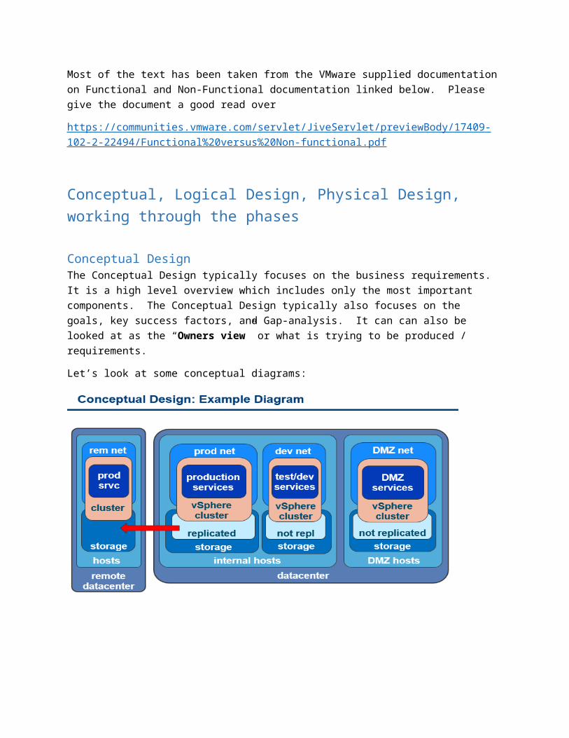
Conceptual DesignThe Conceptual Design typically focuses on the business requirements. It is a high level overview which includes only the most important components. The Conceptual Design typically also focuses on the goals, key success factors, and Gap-analysis. It can can also be looked at as the “Owners view” or what is trying to be produced / requirements.
Let’s look at some conceptual diagrams:

Another way to look at the Conceptual Design is a like a table of contents filled with requirements, key success factors, what needs to be built to meet the projects goals. You will use your conceptual design as a table of contents for what you will build out in the Logical and Physical design phases.
Let’s use the middle diagram as our example. This diagram is a conceptual diagram for a stretch cluster. With that in mind some of the requirements for this could be, Zero down times, SLA of 99.999% or 99.9999%, reduced DR costs, faster recovery times during outages, lower TCO, higher ROI etc. With this established we can look at this design and show it to Management, CEO’s, CIO, whoever despite their technical knowledge and show how their requirements are being met at a very high level. It also sets the stage for our Logical Design as we now know what needs to be built.
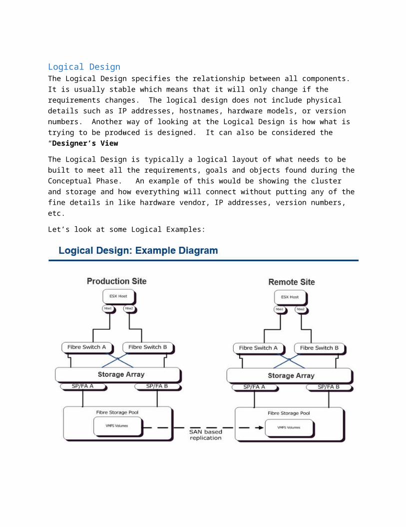
Logical DesignThe Logical Design specifies the relationship between all components. It is usually stable which means that it will only change if the requirements changes. The logical design does not include physical details such as IP addresses, hostnames, hardware models, or version numbers. Another way of looking at the Logical Design is how what is trying to be produced is designed. It can also be considered the “Designer’s View”
The Logical Design is typically a logical layout of what needs to be built to meet all the requirements, goals and objects found during the Conceptual Phase. An example of this would be showing the cluster and storage and how everything will connect without putting any of the fine details in like hardware vendor, IP addresses, version numbers, etc.
Let’s look at some Logical Examples:

Now these are two different logical designs, however both are logical designs. I particularly like the first diagram better as it is a very typically logical design. Both examples however show logically what you are trying to build to accomplish the requirements stipulated in the conceptual design.
Playing back on our original example of the stretch cluster let’s look at the first diagram. This could be used to depict what was laid out conceptually previously. However since this is the designers view we are more interested on how things are going to connect. How packets are going to get from point A to point B. How we are going to logically setup the systems so when we get to the physical design phase we already know what we must do and just need the finite details of it. IE) How many connections, what kind of hba’s, what kind of switches, what kind of hardware, IP addresses, version numbers, ect.
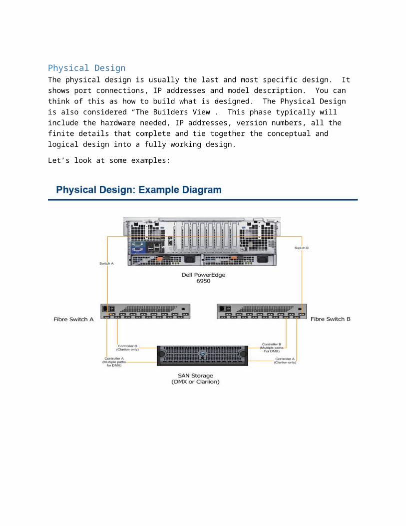
Physical DesignThe physical design is usually the last and most specific design. It shows port connections, IP addresses and model description. You can think of this as how to build what is designed. The Physical Design is also considered “The Builders View”. This phase typically will include the hardware needed, IP addresses, version numbers, all the finite details that complete and tie together the conceptual and logical design into a fully working design.
Let’s look at some examples:

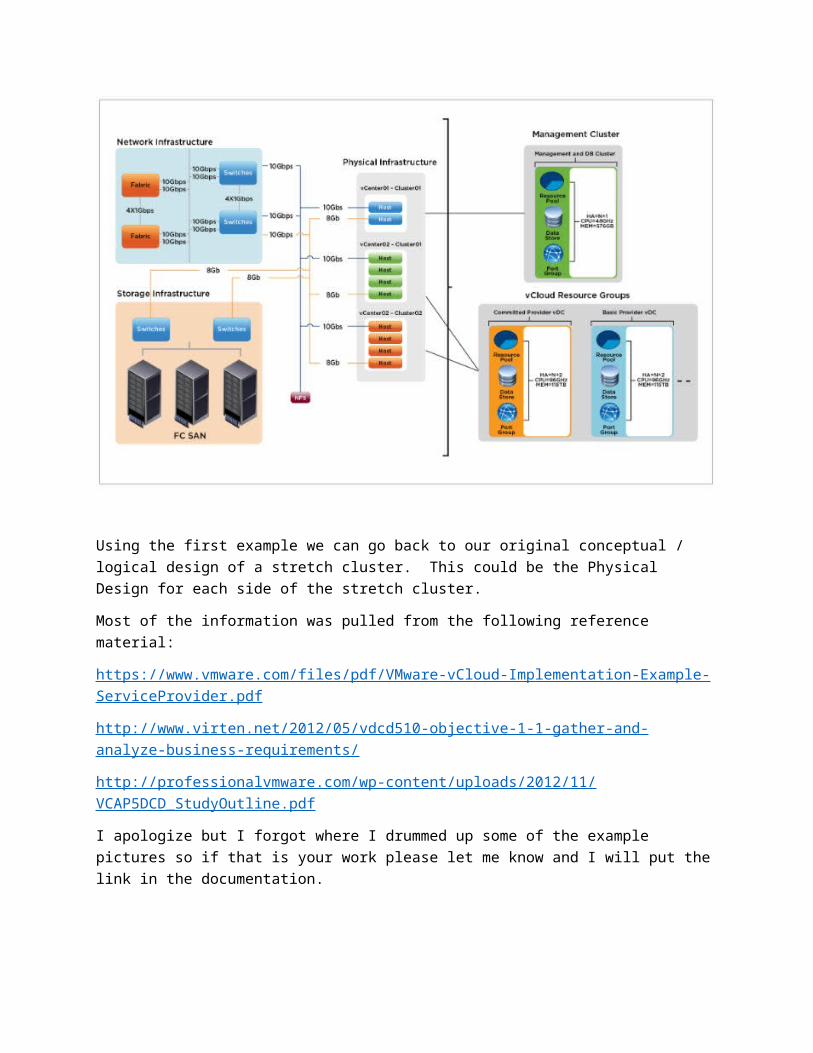
Using the first example we can go back to our original conceptual / logical design of a stretch cluster. This could be the Physical Design for each side of the stretch cluster.
Most of the information was pulled from the following reference material:
https://www.vmware.com/files/pdf/VMware-vCloud-Implementation-Example-ServiceProvider.pdf
http://www.virten.net/2012/05/vdcd510-objective-1-1-gather-and-analyze-business-requirements/
http://professionalvmware.com/wp-content/uploads/2012/11/VCAP5DCD_StudyOutline.pdf
I apologize but I forgot where I drummed up some of the example pictures so if that is your work please let me know and I will put the link in the documentation.
Storage Best Practices, Fiber, iSCSI, NFS, PSP(Path Selection Policies)Storage best practices in VMware can be found all over the net, Vmware support articles, PDF’s, etc. The problem is there is Storage Defaults and Storage Best Practices. When it comes to the DCD exam you will want to build out your designs to Best Practices. It is also VERY important to read the scenario closely as there will sometimes be clues on which PSP they want or they may outright tell you. Furthermore storage is broken down into three sections NMP, SATP, NMP. Let’s let look at these options in more detail.
Note: ***vmware native Multipathing algorithm => Fixed, MRU, Round-Robin***
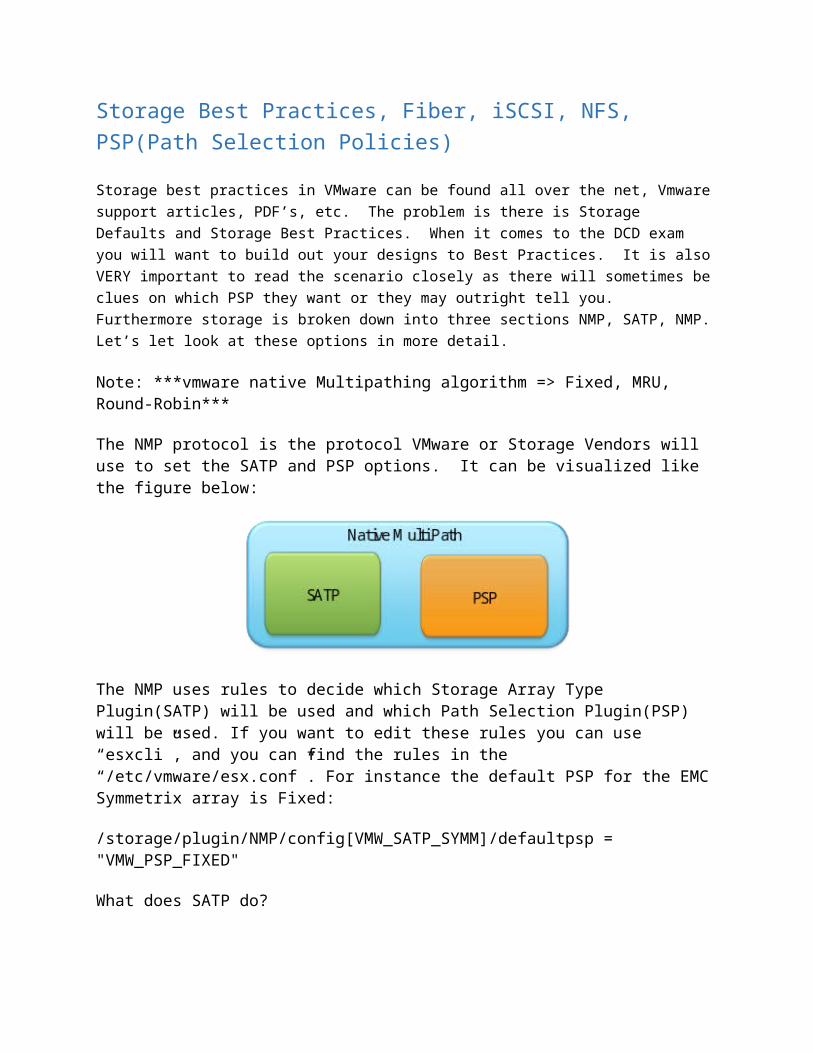
The NMP protocol is the protocol VMware or Storage Vendors will use to set the SATP and PSP options. It can be visualized like the figure below:
The NMP uses rules to decide which Storage Array Type Plugin(SATP) will be used and which Path Selection Plugin(PSP) will be used. If you want to edit these rules you can use “esxcli”, and you can find the rules in the “/etc/vmware/esx.conf”. For instance the default PSP for the EMC Symmetrix array is Fixed:
/storage/plugin/NMP/config[VMW_SATP_SYMM]/defaultpsp = "VMW_PSP_FIXED"
What does SATP do?
The SATP handles path fail-overs, it’s as simple as that. This of course will be reported back to the NMP, because the NMP is responsible for the i/o flow. The SATP will monitor the health of a path and take the required action depending on the type of array. Nothing more, nothing less.
What does PSP do?
The PSP determines which path will be used for an I/O request, in other words the PSP deals with the Fixed, MRU and Round-Robin algorithms.
Keep in mind that the type of PSP that will be used has already been pre-configured, it’s not the PSP that decides if it will do Fixed or MRU, it’s the NMP that decides this based on pre-defined rules stated above.
MPP
What’s next? That would be a Multipathing Plugin(MPP). vmware NMP is built by VMware, on the other hand MPP’s are developed by the vendors of the arrays. EMC is one of the vendors that already demonstrated their MPP. Example: EMC’s MPP is known as Powerpath for ESX.
** Note the DCD will not ask you on MPP as it is unfair to ask questions on vendors technologies as candidate may have never worked with it before which is unfair to the tester. This rule goes for most things in the DCD. If there is ever a choice between using a VMware solution or a Vendors solution, pick the VMware solution on the exam.
-------------------------------------------------------------------------------------------------
Different types of storage and multipathing policy:
Active-Active :- The storage system have two controllers and LUN(Virtual disk or storage device) can be accessed or host can perform I/O via both the controllers.
Active-Passive :- Host can have I/O to and from one LUN via one controller only (via the active controller- owner - of the LUN and not via the other )
ALUA:- Asymmetric Logic Unit Access is where the storage system simulates the active-active feature (LUN can be accessed via both controllers but only one will be the owner of it)
Example: EMC VNX 5300 is not truly active/active array. It just an asymmetric logical unit access array.
For that reason ESX detect this EMC VNX 5300 as a ALUA storage and uses VMW_SATP_ALUA_CX SATP plug-in.
Whether a storage system is active/active, active/passive or ALUA, the vmware PSP can be FIXED, MRU or RR based on array type. The thumb rule is:
1.) For an Active/Passive array you would need to set the path policy (PSP) to “Most Recently Used“.(The default PSP for active/passive storage devices is VMW_PSP_MRU). There is no preferred path setting with the MRU policy.
2.) An Active/Active array should have the path policy set to “Fixed“. (The default PSP for active-active storage devices is VMW_PSP_FIXED.)
Important: VMware does not recommend you use VMW_PSP_FIXED for devices (array) that have the VMW_SATP_ALUA storage array type policy assigned to them. This is because (As per my understanding) ALUA is not truly Active/active storage, so in this case VMW_PSP_MRU should be used.
3.) For both active/active and active/passive array we can choose “round robin (RR)”
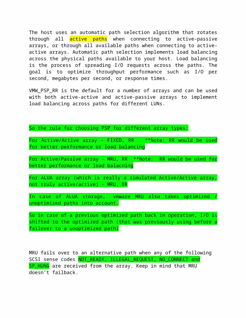
The host uses an automatic path selection algorithm that rotates through all active paths when connecting to active-passive arrays, or through all available paths when connecting to active-active arrays. Automatic path selection implements load balancing across the physical paths available to your host. Load balancing is the process of spreading I/O requests across the paths. The goal is to optimize throughput performance such as I/O per second, megabytes per second, or response times.
VMW_PSP_RR is the default for a number of arrays and can be used with both active-active and active-passive arrays to implement load balancing across paths for different LUNs.
So the rule for choosing PSP for different array types:
For Active/Active array – FIXED, RR **Note: RR would be used for better performance or load balancing
For Active/Passive array – MRU, RR **Note: RR would be used for better performance or load balacning
For ALUA array (which is really a simulated Active/Active array, not truly active/active) – MRU, RR
In case of ALUA storage, vmware MRU also takes optimized / unoptimized paths into account.
So in case of a previous optimized path back in operation, I/O is shifted to the optimized path (that was previously using before a failover to a unoptimized path)
MRU fails over to an alternative path when any of the following SCSI sense codes NOT_READY, ILLEGAL_REQUEST, NO_CONNECT and SP_HUNG are received from the array. Keep in mind that MRU doesn’t failback.
For Active/Active SAN’s, the Fixed path policy a fail over only occurs when the SCSI sense code “NO_CONNECT” is received from the array. When the path returns a fail back will occur.
As you can see, four against just one SCSI sense code. You can imagine what happens if you change MRU to Fixed when it’s not supported by the array. SCSI sense codes will be sent out from the array, but ESX isn’t expecting them (NOT_READY, ILLEGAL_REQUEST, SP_HUNG) and will not do a path fail over.
Over all on the DCD exam pay close attention to what they are asking for the PSP policy. If you have a choice between FIXED/RR or MRU/RR it would stand to reason either could be used and be correct. However again, be looking for clues or anything that could tilt your decision. IE.) Best performance, or load balancing is a requirement. In most cases I would use the better performing option of RR if I have a choice and nothing is stated to help me with my dicision.
Network IO Control (Shares & Physical Adapter Limits)
Network IOC Control (NIOC) Is a great new feature that is available in vSphere 5.0+ in Virtual Distributed Switches(VDS). You will need to have a VDS setup to take advantages of these new features
Here is two great links to help understand how NIOC works under the hood:
http://blogs.vmware.com/vsphere/2013/01/vsphere-5-1-network-io-control-nioc-architecture-old-and-new.html#more-6888
http://blogs.vmware.com/vsphere/tag/traffic-management
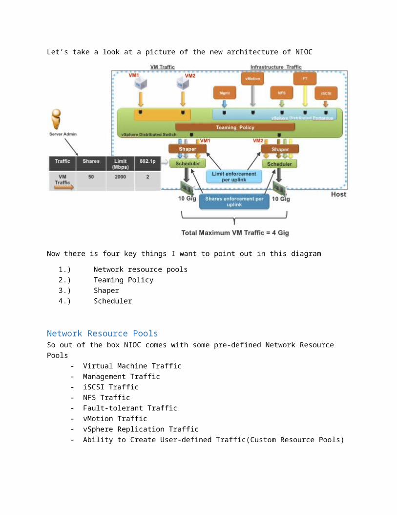
Let’s take a look at a picture of the new architecture of NIOC
Now there is four key things I want to point out in this diagram
1.) Network resource pools2.) Teaming Policy3.) Shaper4.) Scheduler
Network Resource PoolsSo out of the box NIOC comes with some pre-defined Network Resource Pools
- Virtual Machine Traffic- Management Traffic- iSCSI Traffic- NFS Traffic- Fault-tolerant Traffic- vMotion Traffic- vSphere Replication Traffic- Ability to Create User-defined Traffic(Custom Resource Pools)
These are like the User Defined Network Resource Pools but are just pre-setup for you. You don’t have to use them if you don’t want to but they are there. The most important part to note in this list probably the VM Traffic. This will be used for any VM’s that do not have a User-defined Network Resource Pool setup for a port group. So when setting up your limits or shares this is very important. To know.
Another thing to note is that Limits will always over ride shares. Meaning if you have a limit set to 2Mbps that is the most that portgroup can ever use, even if it has a higher share value or there is additional bandwidth available on the NIC. Also Shares on Network Resource Pools will only kick into effect during times of contention. If you never reach contention on your network the shares will never be taken into consideration.
Teaming PolicyThis is the layer where teaming policy defined at the port group level gets applied. Based on the choice of the load balancing algorithm and the active/passive uplink configurations at the port group level, this layer will determine which traffic from the virtual ports (vnic,vmknic) will be sent over the which physical NICs (uplinks).
So in simple terms this comes down to whether you setup your port groups in active/active or active/standby. Really the only thing you have to take into consideration here is if you are running an active/active configuration on a port group or active/standby. This is because after the traffic passes through the teaming policy and decides which NIC/uplink will be handling the traffic the traffic is then passed to the Shaper, which can affect your limits. This is due to the new 5.1 NIOC architecture which is described very well in the link provided.
*NOTE: For exam purposes we don’t have to worry about how the Shaper affects the limits, we just have to set the proper limits on the exam. So for example if the exam asks to set a limit of 3GB on iSCSI you just have to set a limit of 3GB, you don’t have to worry about the fact that the Shaper could be giving 3GB per each Shaper for a total of 6GB limit depending on the teaming policy architecture
ShaperThis is the layer where the Limit parameter configured for a traffic type is enforced. For example, if the virtual machine traffic is limited to 2 Gig any additional virtual machine traffic will be dropped at this layer even if physical NICs have capacity
Not much else to say here. This is where the Limits are enforced. One thing to note however is the change in Architecture from 5.0 to 5.1. The new architecture has a Shaper per NIC/Uplink so this can affect the overall max Limit of traffic allowed based on the teaming policy. The link to the blog goes into this in great detail so I highly recommend giving it a good read.
The long and short of it is this: Since a Sharper is assigned per NIC/Uplink, a Limit assigned to a Network Resource Pool could be double depending on how the traffic flows. For example lets say you have a Portgroup called Production with an Orig Port ID Active/Active teaming policy with two VM’s in it. Each VM will be placed on 1 NIC for load balancing purposes. If you have the limit set on Production to 2GB, each NIC gets a Limit of 2GB meaning your two VM’s will have a grand total limit of 4GB(2GBNIC1 + 2GBNIC2 on the network.
This is not really relevant for the exam as stated above in the note, as the exam only cares about the overall limit and doesn’t worry about the Shaper, however in a real world scenario it is something you may want to take into consideration.
SchedulerIn this layer scheduler schedules traffic on physical NIC based on the share configurations per traffic type. There is one scheduler instantiated per physical NIC, and it handles all the traffic that is sent by the teaming layer. The share parameter is used to decide what percentage of physical NIC bandwidth is allocated to that particular traffic type.
Again I highly recommend a good read through the links posted above as the blog does a fantastic job on describing how this works.
The long and short of it is this: Even though the Scheduler is per NIC/Uplink like the Shaper you don’t have to worry as much about doubling your traffic as no matter which NIC your traffic falls on it will still be judged by its share value and treated accordingly. So you can look at the share values as more of a whole. However if you would like a more detailed look at it feel free to read the blogs posted above or get in touch with me for a discussion.
*Note: For the exam purposes when they ask you setup a share they are look at it as a whole
How to setup Limits, Physical Adapter Shares, and Share ValuesHere is a link that goes over the steps to create a custom or user-defined Network Resource Pool
http://pubs.vmware.com/vsphere-51/index.jsp?topic=%2Fcom.vmware.vsphere.networking.doc%2FGUID-7D5D0EBD-B105-4E55-9BB0-20A4075A9342.html
Let’s go over the steps:
1. Login to the vSphere Client and select Networking2. Select the vSphere Distributed Switch in the inventory Pane3. On the Resource Allocation tab, click New Network Resource Pool4. Type a Name for the network resource pool5. (Optional) Type a Description for the network resource pool6. Select the Physical Adapter Shares for the network resource pool

Option DescriptionCustom Type a specific number of shares, from 1 to
100 for this network resource poolHigh Sets the shares for this resource pool to 100Normal Sets the shares for this resource pool to 50Low Sets the shares for this resource pool to 25
7. Set the Host Limit for the network resource pool in megabits per second or select Unlimited8. (Optional) Select the QoS priority tag for the network resource pool9. Click OK
So the important thing to note here is the Physical Adapter shares directly affect the share values. One could even think of them as the same thing. The three pre-defined values of High, Normal, and Low have re-defined share values essentially doubling it each time you go up one. The only exception to this is the custom value, which lets you choose what your Share value for the Physical Adapter.
*Note: So during the exam when filling out these types of questions if you have a Physical Adapter share of Normal you know the Share value has to be 50. The same goes for the rest of the values unless a custom value comes into the equation.
Practice Question:
You have a four VM port groups in your environment: VM Networks, Tier 1, Tier 2, and Tier 3.
VM Network is used as a staging area while building new servers, patching, etc. The client would like this network to have highest priority during times of content so the build process is not slowed down
The client would like the priority for the tiers to go from High-Low (Tier1-Tier3) during times of contention. With Tier 1 getting twice the amount of network resources than Tier2, and Tier 2 getting twice the amount of network resources than Tier3.
The client would like to limit iSCSI traffic to 2GB as it is just used for testing.
vMotion and FT require twice the priority over the Management network.
Fill out the following table with the proper limits, Physical Adapter Shares, and Share Values
Network Resource Pool Host Limit Mbps Physical Adapters Shares
Shares Values
ManagementvMotioniSCSIVM TrafficTier1Tier2
Tier3
Answer:
Network Resource Pool Host Limit Mbps Physical Adapters Shares
Shares Values
Management Unlimited LOW 25vMotion Unlimited NORMAL 50iSCSI 2000 NORMAL 50VM Traffic Unlimited HIGH 100Tier1 Unlimited HIGH 100Tier2 Unlimited NORMAL 50Tier3 Unlimited LOW 25
Additonal information for NIOC can be found in the link below
http://pubs.vmware.com/vsphere-51/index.jsp#com.vmware.vsphere.networking.doc/GUID-ADEA0213-C969-43E4-B1F4-66D4A916EBDF.html
AutodeployLink https://labs.vmware.com/wp-content/uploads/2010/08/autodeploy_fling.pdf
First Boot Overview
When a host that has not yet been provisioned with vSphere Auto Deploy boots (first boot), the host interacts with several Auto Deploy components.
1. When the administrator turns on a host, the host starts a PXE boot sequence. The DHCP Server assigns an IP address to the host and instructs the host to contact the TFTP server.

2. The host contacts the TFTP server and downloads the iPXE file (executable boot loader) and an iPXE configuration file.
3. iPXE starts executing. The configuration file instructs the host to make a HTTP boot request to the Auto Deploy server. The HTTP request includes hardware and network information.
4. In response, the Auto Deploy server performs these tasks:a. Queries the rules engine for information about the host.b. Streams the components specified in the image profile, the optional host profile, and
optional vCenter Server location information.
5. The host boots using the image profile. If the Auto Deploy server provided a host profile, the host profile is applied to the host.
6. Auto Deploy adds the host to the vCenter Server system that Auto Deploy is registered with.
a. If a rule specifies a target folder or cluster on the vCenter Server system, the host is placed in that folder or cluster. The target folder must be under a data center.
b. If no rule exists that specifies a vCenter Server inventory location, Auto Deploy adds the host to the first datacenter displayed in the vSphere Web Client UI.
7. (Optional) If the host profile requires the user to specify certain information, such as a static IP address, the host is placed in maintenance mode when the host is added to the vCenter Server system. You must reapply the host profile and update the host customization to have the host exit maintenance mode. When you update the host customization, answer any questions when prompted.
8. If the host is part of a DRS cluster, virtual machines from other hosts might be migrated to the host after the host has successfully been added to the vCenter Server system.
Implementation StepsUpgrading vCenterHere is a link that goes over the step by step process of upgrading vCenter: http://kb.vmware.com/selfservice/microsites/search.do?language=en_US&cmd=displayKC&externalId=2053130
Whether you are using the Simple Install method (one shot upgrade) or upgrading separately (if you have different components divided out onto separate servers), the process is the same:
1. Upgrade SSO2. Upgrade vSphere web client3. Upgrade vSphere Inventory Service4. Upgrade vCenter Server
vDSMigrating DatacentersMigrating vDS
vSphere Backup Data ProtectorvSphere Replication and SRMUpstream/Downstream Dependencies

VSAN
Hypervisor-based software-defined storage Aggregates local HDDs to provide a clustered data store for VM consumption Leverages local SSDs as a cache Distributed object-based RAIN architecture provides no single point of failure Policy-based VM-storage management for end-to-end SLA enforcement Integrated with vCenter Integrated with vSphere HA, DRS and vMotion Scale-Out Storage: 3-32 nodes
o Petabytes of capacity

2 Million IOPS Does not support VMDKs larger than 2TB-512b Does not support FT, DPM, Storage DRS or Storage I/O Control.
VSAN Requirements
Needs ESXi 5.5 U1 or greater A HBA or a Pass-thru RAID Controller is required (a RAID Controller which can present disks
directly to the host without a RAID configuration) A combination of HDD & SSD devices are required (a minimum of 1 HDD & 1 SSD [SAS or SATA]),
although it is expected that SSDs make up 10% of total storage The SSD will provide both a write buffer and a read cache. The more SSD capacity in the host,
the greater the performance since more I/O can be cached. Not every node in a VSAN cluster needs to have local storage. Hosts with no local storage can
still leverage distributed datastore. Each vSphere host must have at least one network interface card (NIC). The NIC must be 1Gb
capable. However,as a best practice, VMware is recommending 10Gb network interface cards. A Distributed Switch can be optionally configured between all hosts in the VSAN cluster,
although VMware Standard Switches (VSS) will also work. A Virtual SAN VMkernel port must be configured for each host. With a Distributed Switch, NIOC
can also be enabled to dedicate bandwidth to the VSAN network. The VMkernel port is labeled Virtual SAN. This port is used for inter-cluster node communication
and also for read and writes when one of the vSphere hosts in the cluster owns a particular virtual machine, but the actual data blocks making up the virtual machine files are located on a different vSphere host in the cluster. In this case, I/O will need to traverse the network configured between the hosts in the cluster.