vce - physics unit 4 topic 1 - cyberchalky! · pdf filedrouin secondary college vce physics...
TRANSCRIPT
Drouin Secondary College VCE Physics Unit 4: Electric Power
Page 1
VCE - PHYSICS
UNIT 4
TOPIC 1
ELECTRIC POWER
TOPIC NOTES
Drouin Secondary College VCE Physics Unit 4: Electric Power
Page 2
Unit Outline This unit covers the following areas:
1. Apply a field model to magnetic phenomena including shapes and directions produced by bar magnets and by currents in wires, coils and solenoids
2. Quantify magnetic forces on current carrying wires using F = IlB, where the direction of I and B are either perpendicular to, or parallel to, each other.
3. Describe the operation of simple DC motors. 4. Apply a field model to define magnetic flux Φ using Φ = BA and the qualitative effect of differing angles
between the coil and the field. 5. Explain the generation of voltage, including AC voltage, in terms of rate of change of magnetic flux
(Faraday’s Law) the direction of the induced current (Lenz’s Law) and the number of loops through which the flux passes including calculations using induced ε = -N dΦ/dt
6. Describe the production of Voltage in generators and AC voltages in alternators including in the use of commutators and slip rings
7. Compare sinusoidal AC voltages produced as a result of uniform rotation of a loop in a constant magnetic flux in terms of frequency, period, amplitude, peak to peak voltage and peak to peak current.
8. Use RMS values for a sinusoidal AC voltage VRMS = Vp/√2 and IRMS = IP/√2 and interpret RMS in terms of the DC supply that provides the same power as an AC supply
9. Compare and contrast DC motors generators and alternators 10. Explain transformer action modelled in terms of electromagnetic induction for an ideal transformer
qualitatively and using the number of turns in the primary and secondary coils voltage and current 11. Model mathematically power supplied as P = VI and transmission losses using voltage drop V = IR and
power loss p = I2R 12. Explain the use of transformers in an electricity distribution system. 13. Use safe and responsible practices when working with electricity and electrical measurement
Chapter 1 1.0 Magnetic Fields All magnets have poles labelled as North and South:
Like poles __________
Unlike poles _____________
Magnets generate ______________ in the space surrounding them.
The concept of “a field” is an important concept in our study of Physics.
A Field is defined as a “region of ____________________”.
In a Magnetic Field, magnetically susceptible materials are subject to an influence.
They will experience a _________________ when placed in the field.
The __________________ of the magnetic field is determined by the size of the
force experienced by a Unit North Pole* placed at the point of interest.
*Does not yet exist, but physicists hope to produce one soon.
Drouin Secondary College VCE Physics Unit 4: Electric Power
Page 3
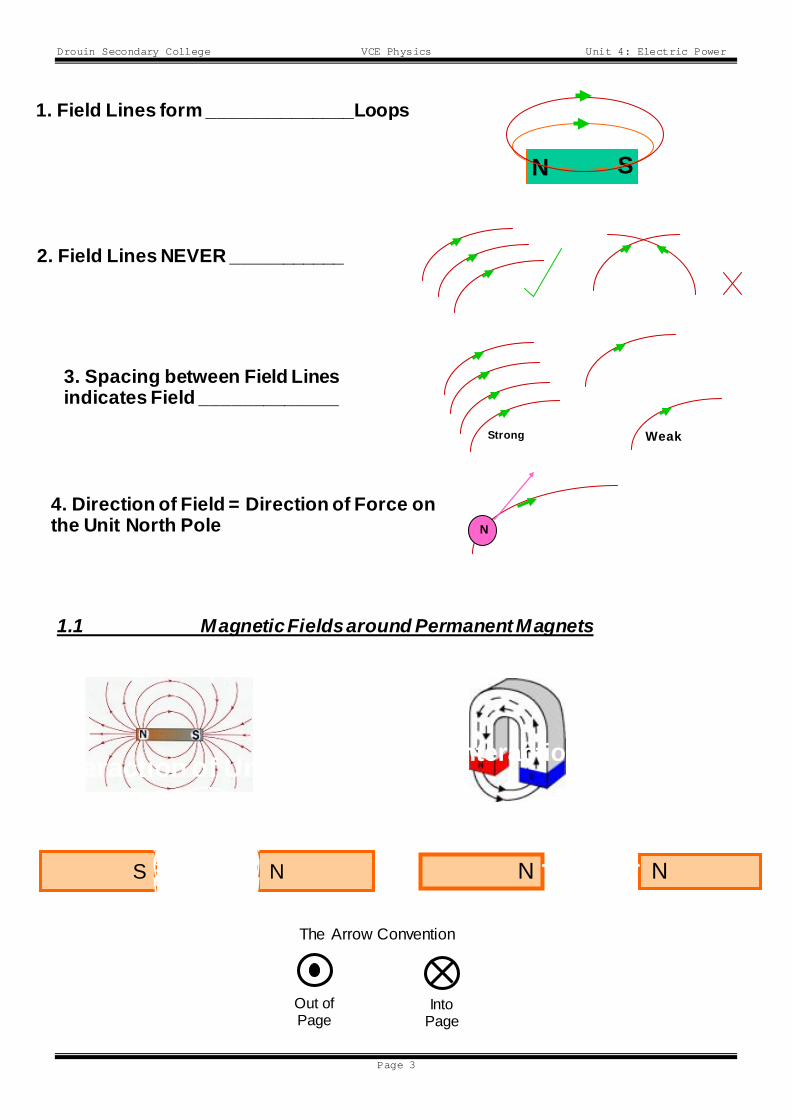
1.1 Magnetic Fields around Permanent Magnets
N S
1. Field Lines form ______________Loops
Permanent Magnet
2. Field Lines NEVER ___________
Strong Weak
3. Spacing between Field Lines indicates Field _____________
N 4. Direction of Field = Direction of Force on the Unit North Pole
Horsesh
N N
Interaction of Like Poles
S N
Interaction of Unlike
The Arrow Convention
Out of Page
Into Page
Drouin Secondary College VCE Physics Unit 4: Electric Power
Page 4
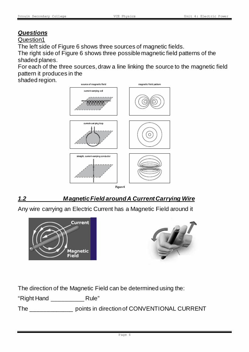
Questions Question1 The left side of Figure 6 shows three sources of magnetic fields. The right side of Figure 6 shows three possible magnetic field patterns of the shaded planes. For each of the three sources, draw a line linking the source to the magnetic field pattern it produces in the shaded region. 1.2 Magnetic Field around A Current Carrying Wire Any wire carrying an Electric Current has a Magnetic Field around it
The direction of the Magnetic Field can be determined using the:
“Right Hand __________ Rule”
The _____________ points in direction of CONVENTIONAL CURRENT

Drouin Secondary College VCE Physics Unit 4: Electric Power
Page 5
The ______________ CURL in direction of MAGNETIC FIELD
Questions Question 2: Draw the lines representing the magnetic field resulting from the straight current-carrying conductor in the figure below. A cross-section of the conductor is shown with the current direction indicated by a dot. You should show give an indication of field shape, direction & relative field strength. Question 3: Two wires carry current in opposite directions as shown in the diagram below. The current in wire Y is twice the current in wire X. Point Q is midway between wires X and Y.
Use the following key for your answers: A. To the right B. To the left C. Up D. Down E. Into the page F. Out of the Page G. Zero
Which of the following best describes the direction of the resultant magnetic field at point Q
Question 4: The current in wire X is reversed. Both conductors now have current passing from right to left. Which alternative would now represent the resultant magnetic field?
Drouin Secondary College VCE Physics Unit 4: Electric Power
Page 6
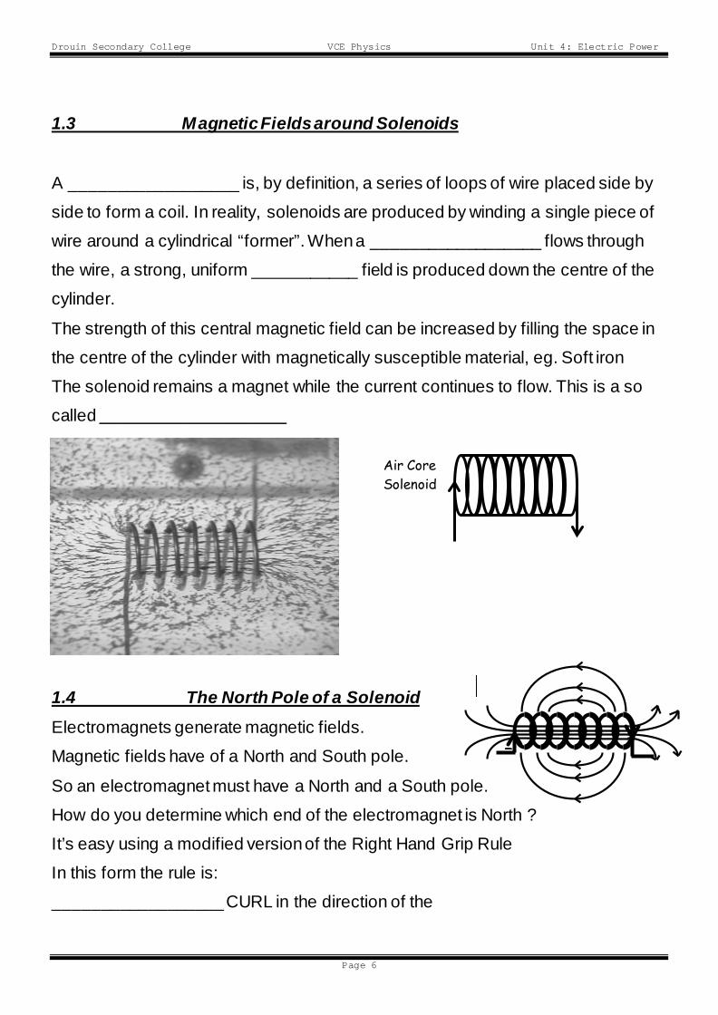
1.3 Magnetic Fields around Solenoids
A __________________ is, by definition, a series of loops of wire placed side by
side to form a coil. In reality, solenoids are produced by winding a single piece of
wire around a cylindrical “former”. When a __________________ flows through
the wire, a strong, uniform ___________ field is produced down the centre of the
cylinder.
The strength of this central magnetic field can be increased by filling the space in
the centre of the cylinder with magnetically susceptible material, eg. Soft iron
The solenoid remains a magnet while the current continues to flow. This is a so
called _______________________
1.4 The North Pole of a Solenoid Electromagnets generate magnetic fields.
Magnetic fields have of a North and South pole.
So an electromagnet must have a North and a South pole.
How do you determine which end of the electromagnet is North ?
It’s easy using a modified version of the Right Hand Grip Rule
In this form the rule is:
__________________ CURL in the direction of the
Air Core Solenoid
I
Drouin Secondary College VCE Physics Unit 4: Electric Power
Page 7
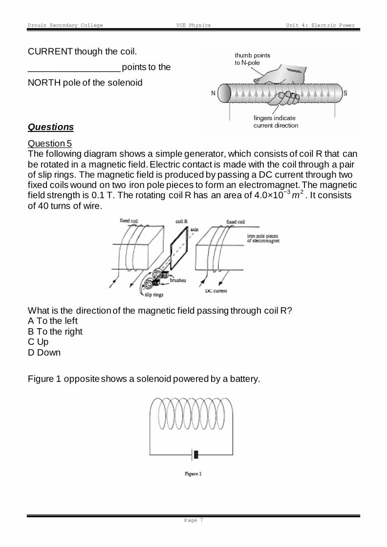
CURRENT though the coil.
__________________ points to the
NORTH pole of the solenoid
Questions
Question 5 The following diagram shows a simple generator, which consists of coil R that can be rotated in a magnetic field. Electric contact is made with the coil through a pair of slip rings. The magnetic field is produced by passing a DC current through two fixed coils wound on two iron pole pieces to form an electromagnet. The magnetic field strength is 0.1 T. The rotating coil R has an area of 4.0×10⁻³ m2 . It consists of 40 turns of wire.
What is the direction of the magnetic field passing through coil R? A To the left B To the right C Up D Down
Figure 1 opposite shows a solenoid powered by a battery.
Drouin Secondary College VCE Physics Unit 4: Electric Power
Page 8
Question 6: Complete the diagram above by sketching five magnetic field lines created by the solenoid. Make sure that you clearly show the direction of the field, including both inside and outside the solenoid. Question 7
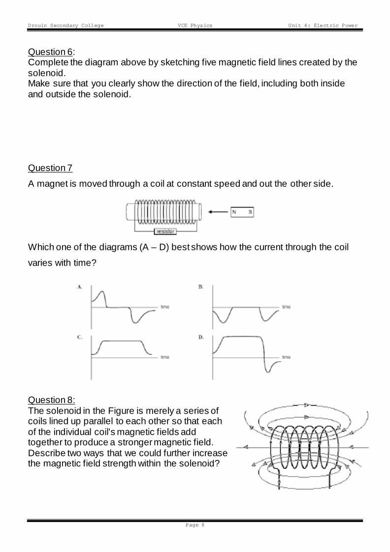
A magnet is moved through a coil at constant speed and out the other side.
Which one of the diagrams (A – D) best shows how the current through the coil
varies with time?
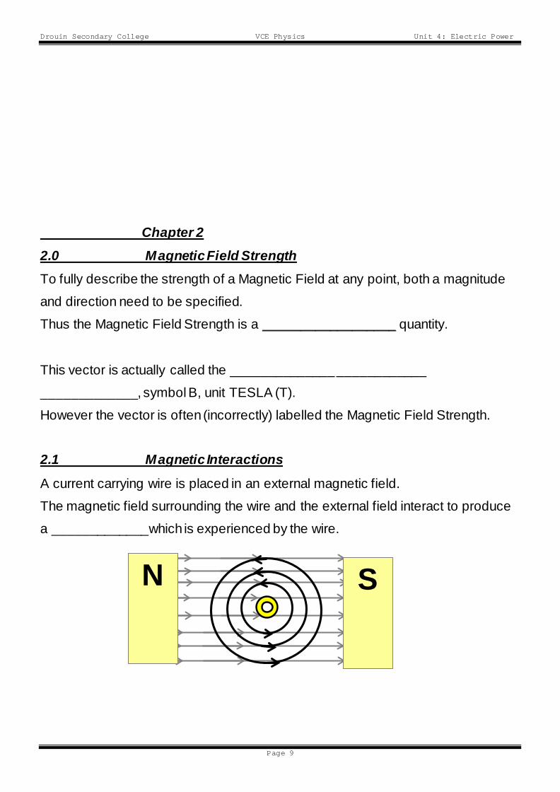
Question 8: The solenoid in the Figure is merely a series of coils lined up parallel to each other so that each of the individual coil's magnetic fields add together to produce a stronger magnetic field. Describe two ways that we could further increase the magnetic field strength within the solenoid?
Drouin Secondary College VCE Physics Unit 4: Electric Power
Page 9
Chapter 2 2.0 Magnetic Field Strength To fully describe the strength of a Magnetic Field at any point, both a magnitude
and direction need to be specified.
Thus the Magnetic Field Strength is a __________________ quantity.
This vector is actually called the ______________ ____________
_____________, symbol B, unit TESLA (T).
However the vector is often (incorrectly) labelled the Magnetic Field Strength.
2.1 Magnetic Interactions
A current carrying wire is placed in an external magnetic field.
The magnetic field surrounding the wire and the external field interact to produce
a _____________which is experienced by the wire.
S N
Drouin Secondary College VCE Physics Unit 4: Electric Power
Page 10
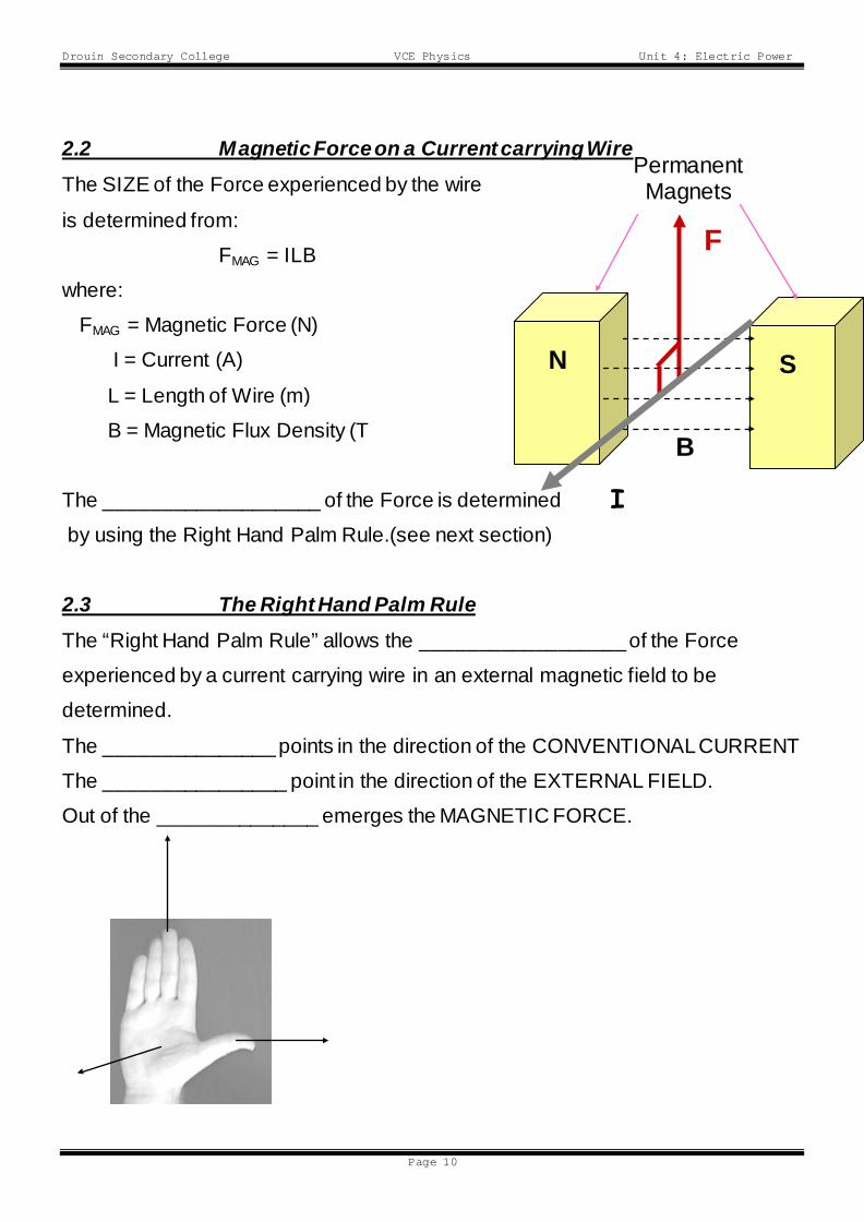
2.2 Magnetic Force on a Current carrying Wire The SIZE of the Force experienced by the wire
is determined from:
FMAG = ILB
where:
FMAG = Magnetic Force (N)
I = Current (A)
L = Length of Wire (m)
B = Magnetic Flux Density (T
The ___________________ of the Force is determined
by using the Right Hand Palm Rule.(see next section)
2.3 The Right Hand Palm Rule The “Right Hand Palm Rule” allows the __________________ of the Force
experienced by a current carrying wire in an external magnetic field to be
determined.
The _______________ points in the direction of the CONVENTIONAL CURRENT
The ________________ point in the direction of the EXTERNAL FIELD.
Out of the ______________ emerges the MAGNETIC FORCE.
F
N S
Permanent Magnets
B
I
Drouin Secondary College VCE Physics Unit 4: Electric Power
Page 11
N.B. The FORCE is MAXIMUM WHEN THE EXTERNAL FIELD (B) is
____________________ to the CURRENT (I).
N.B. The FORCE is ZERO when the FIELD and CURRENT are
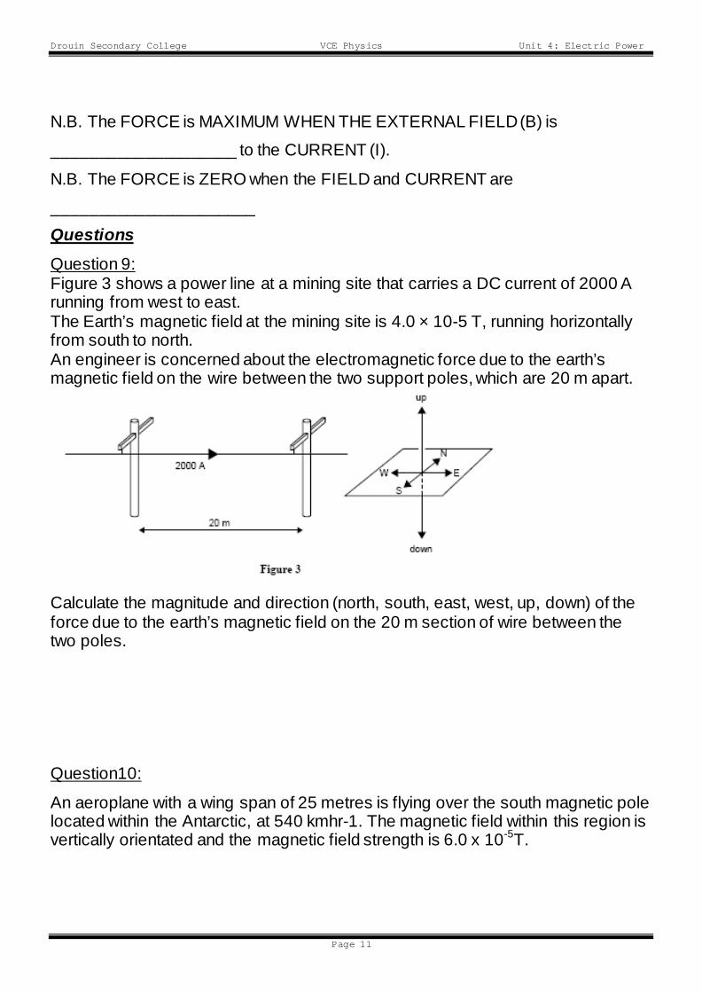
______________________ Questions Question 9: Figure 3 shows a power line at a mining site that carries a DC current of 2000 A running from west to east. The Earth’s magnetic field at the mining site is 4.0 × 10⁻⁵ T, running horizontally from south to north. An engineer is concerned about the electromagnetic force due to the earth’s magnetic field on the wire between the two support poles, which are 20 m apart.
Calculate the magnitude and direction (north, south, east, west, up, down) of the force due to the earth’s magnetic field on the 20 m section of wire between the two poles.
Question10:
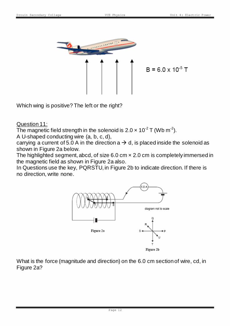
An aeroplane with a wing span of 25 metres is flying over the south magnetic pole located within the Antarctic, at 540 kmhr-1. The magnetic field within this region is vertically orientated and the magnetic field strength is 6.0 x 10⁻⁵T.
Drouin Secondary College VCE Physics Unit 4: Electric Power
Page 12
Which wing is positive? The left or the right? Question 11: The magnetic field strength in the solenoid is 2.0 × 10⁻² T (Wb m-2). A U-shaped conducting wire (a, b, c, d), carrying a current of 5.0 A in the direction a d, is placed inside the solenoid as shown in Figure 2a below. The highlighted segment, abcd, of size 6.0 cm × 2.0 cm is completely immersed in the magnetic field as shown in Figure 2a also. In Questions use the key, PQRSTU, in Figure 2b to indicate direction. If there is no direction, write none. What is the force (magnitude and direction) on the 6.0 cm section of wire, cd, in Figure 2a?
Drouin Secondary College VCE Physics Unit 4: Electric Power
Page 13
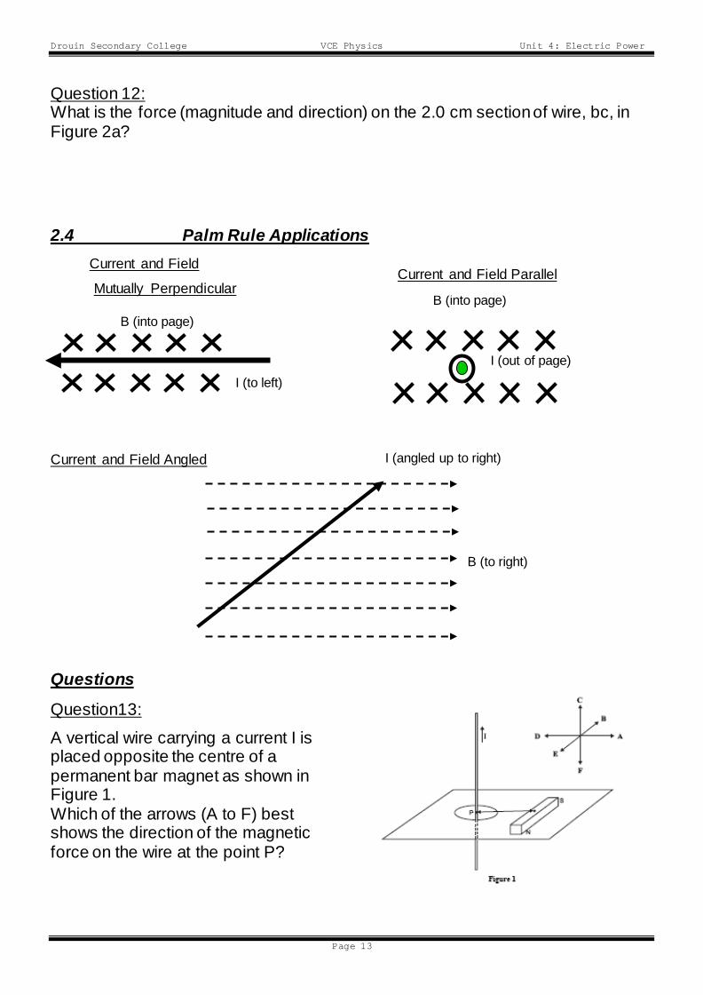
Question 12: What is the force (magnitude and direction) on the 2.0 cm section of wire, bc, in Figure 2a? 2.4 Palm Rule Applications Current and Field Mutually Perpendicular
Current and Field Angled
Questions
Question13:
A vertical wire carrying a current I is placed opposite the centre of a permanent bar magnet as shown in Figure 1. Which of the arrows (A to F) best shows the direction of the magnetic force on the wire at the point P?
B (into page)
I (to left)
B (into page)
I (out of page)
Current and Field Parallel
B (to right)
I (angled up to right)
Drouin Secondary College VCE Physics Unit 4: Electric Power
Page 14
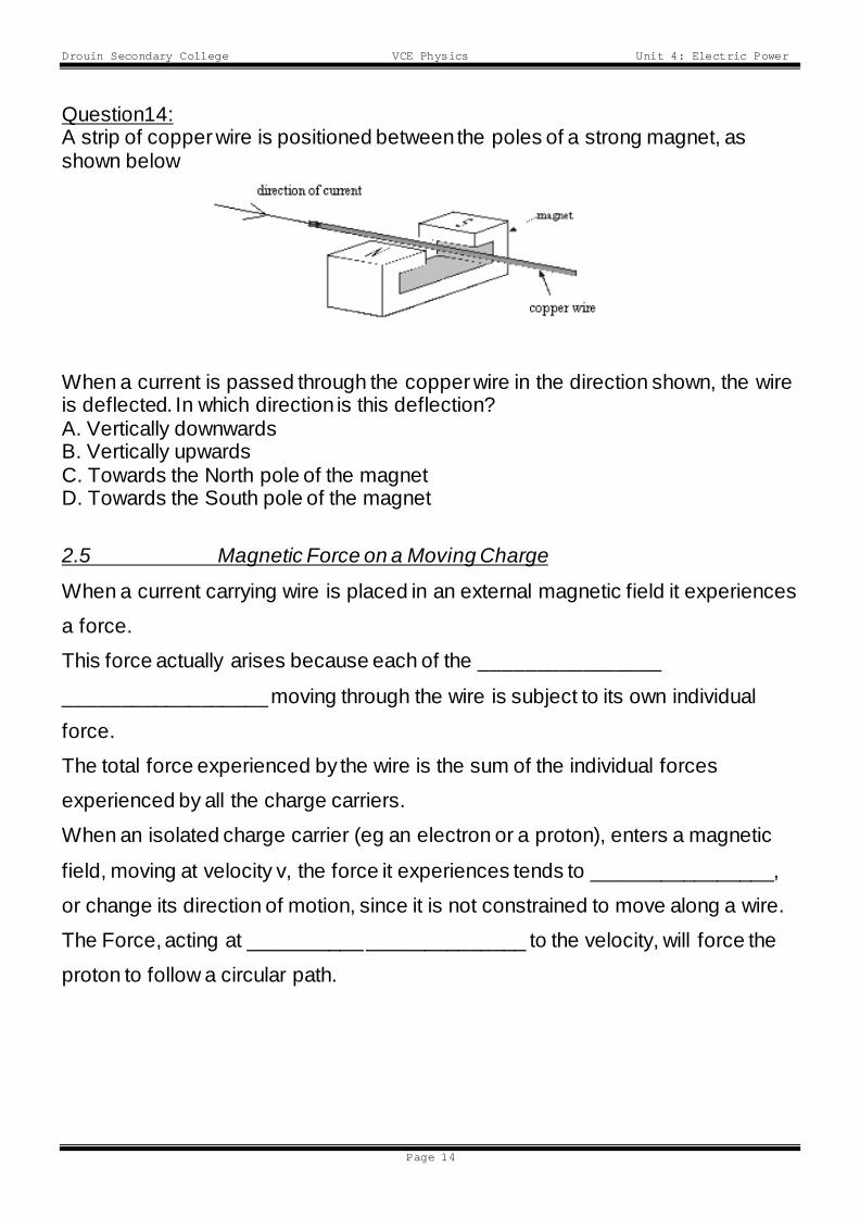
Question14: A strip of copper wire is positioned between the poles of a strong magnet, as shown below
When a current is passed through the copper wire in the direction shown, the wire is deflected. In which direction is this deflection? A. Vertically downwards B. Vertically upwards C. Towards the North pole of the magnet D. Towards the South pole of the magnet
2.5 Magnetic Force on a Moving Charge
When a current carrying wire is placed in an external magnetic field it experiences
a force.
This force actually arises because each of the ________________
__________________ moving through the wire is subject to its own individual
force.
The total force experienced by the wire is the sum of the individual forces
experienced by all the charge carriers.
When an isolated charge carrier (eg an electron or a proton), enters a magnetic
field, moving at velocity v, the force it experiences tends to ________________,
or change its direction of motion, since it is not constrained to move along a wire.
The Force, acting at __________ ______________ to the velocity, will force the
proton to follow a circular path.
Drouin Secondary College VCE Physics Unit 4: Electric Power
Page 15
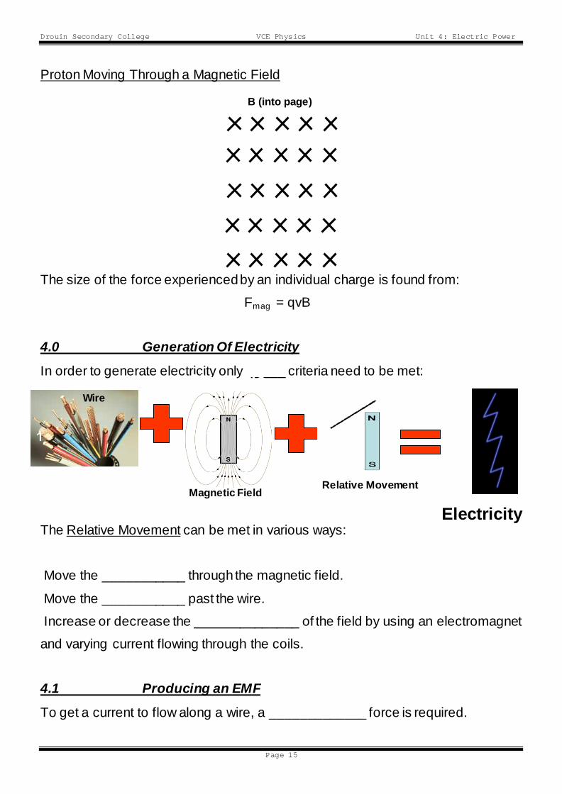
Proton Moving Through a Magnetic Field
The size of the force experienced by an individual charge is found from:
Fmag = qvB
4.0 Generation Of Electricity
In order to generate electricity only _____ criteria need to be met:
The Relative Movement can be met in various ways:
Move the ___________ through the magnetic field.
Move the ___________ past the wire.
Increase or decrease the ______________ of the field by using an electromagnet
and varying current flowing through the coils.
4.1 Producing an EMF
To get a current to flow along a wire, a _____________ force is required.
Wire
1
A piece of
Relative Movement 3
Electricity
B (into page)
Magnetic 2
A Magnetic
Magnetic Field
Drouin Secondary College VCE Physics Unit 4: Electric Power
Page 16
This driving force is VOLTAGE DIFFERENCE between the ends of the wire.
This voltage supplies the charge carriers with the ____________ required to travel
the length of the wire.
This supplier of energy is given a special name and is called the
ELECTROMOTIVE FORCE (EMF)
When a wire “_______ _____________” magnetic field lines, an EMF is
produced between the ends of the wire.
The EMF produced in this situation is called “INDUCED EMF”.
(As always we deal with ___________________ current representing a flow of
positive charges)
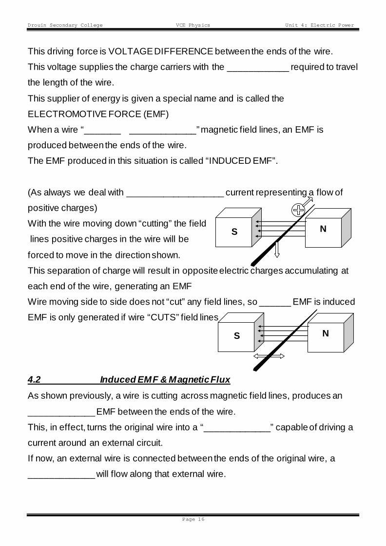
With the wire moving down “cutting” the field
lines positive charges in the wire will be
forced to move in the direction shown.
This separation of charge will result in opposite electric charges accumulating at
each end of the wire, generating an EMF
Wire moving side to side does not “cut” any field lines, so ______ EMF is induced
EMF is only generated if wire “CUTS” field lines
4.2 Induced EMF & Magnetic Flux As shown previously, a wire is cutting across magnetic field lines, produces an
_____________ EMF between the ends of the wire.
This, in effect, turns the original wire into a “_____________” capable of driving a
current around an external circuit.
If now, an external wire is connected between the ends of the original wire, a
_____________ will flow along that external wire.
N S
N S
Drouin Secondary College VCE Physics Unit 4: Electric Power
Page 17
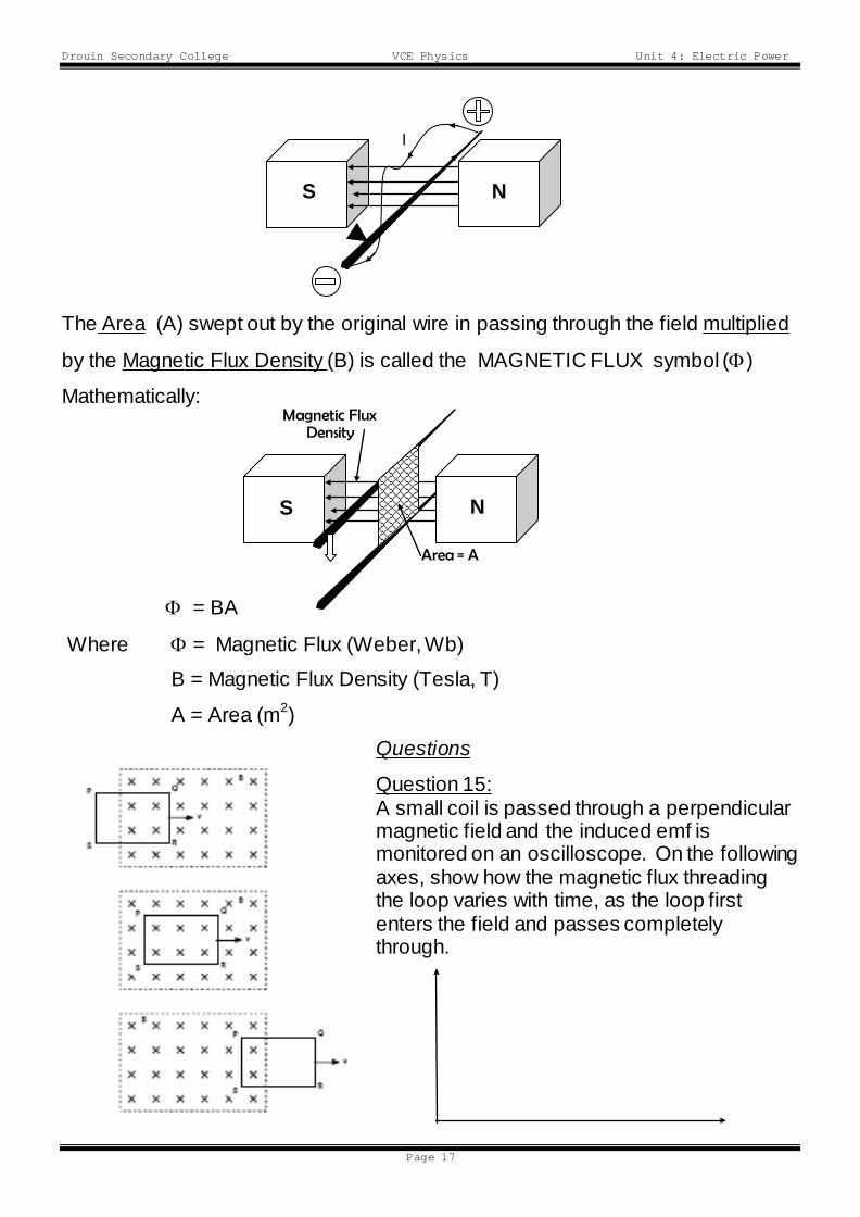
The Area (A) swept out by the original wire in passing through the field multiplied
by the Magnetic Flux Density (B) is called the MAGNETIC FLUX symbol (Φ)
Mathematically:
Φ = BA
Where Φ = Magnetic Flux (Weber, Wb)
B = Magnetic Flux Density (Tesla, T)
A = Area (m2) Questions
Question 15: A small coil is passed through a perpendicular magnetic field and the induced emf is monitored on an oscilloscope. On the following axes, show how the magnetic flux threading the loop varies with time, as the loop first enters the field and passes completely through.
S
I
N
S N
Area = A
Magnetic Flux Density
Drouin Secondary College VCE Physics Unit 4: Electric Power
Page 18
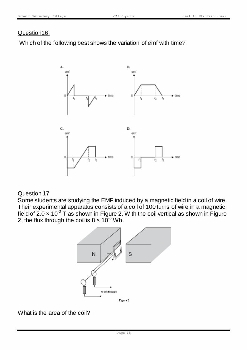
Question16:
Which of the following best shows the variation of emf with time?
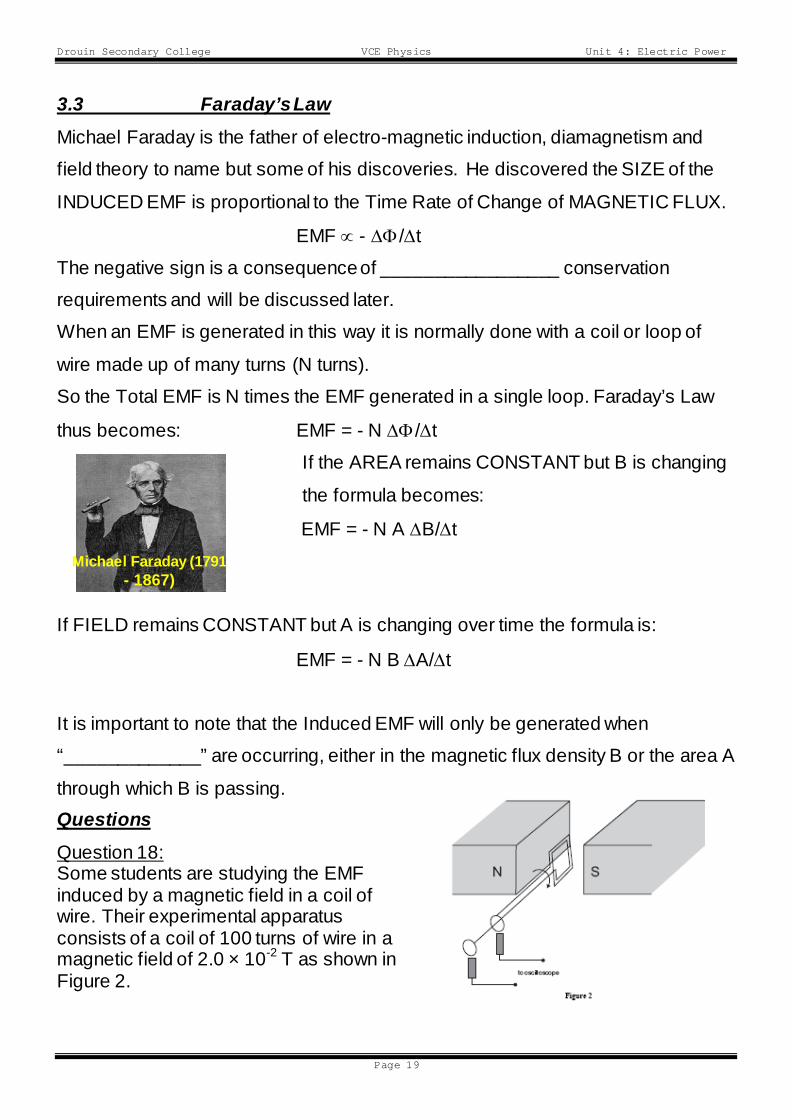
Question 17 Some students are studying the EMF induced by a magnetic field in a coil of wire. Their experimental apparatus consists of a coil of 100 turns of wire in a magnetic field of 2.0 × 10⁻² T as shown in Figure 2. With the coil vertical as shown in Figure 2, the flux through the coil is 8 × 10⁻⁶ Wb.
What is the area of the coil?
Drouin Secondary College VCE Physics Unit 4: Electric Power
Page 19
3.3 Faraday’s Law Michael Faraday is the father of electro-magnetic induction, diamagnetism and
field theory to name but some of his discoveries. He discovered the SIZE of the
INDUCED EMF is proportional to the Time Rate of Change of MAGNETIC FLUX.
EMF ∝ - ∆Φ/∆t
The negative sign is a consequence of _________________ conservation
requirements and will be discussed later.
When an EMF is generated in this way it is normally done with a coil or loop of
wire made up of many turns (N turns).
So the Total EMF is N times the EMF generated in a single loop. Faraday’s Law
thus becomes: EMF = - N ∆Φ/∆t
If the AREA remains CONSTANT but B is changing
the formula becomes:
EMF = - N A ∆B/∆t
If FIELD remains CONSTANT but A is changing over time the formula is:
EMF = - N B ∆A/∆t
It is important to note that the Induced EMF will only be generated when
“_____________” are occurring, either in the magnetic flux density B or the area A
through which B is passing. Questions Question 18: Some students are studying the EMF induced by a magnetic field in a coil of wire. Their experimental apparatus consists of a coil of 100 turns of wire in a magnetic field of 2.0 × 10⁻² T as shown in Figure 2.
Michael Faraday (1791 - 1867)
Drouin Secondary College VCE Physics Unit 4: Electric Power
Page 20
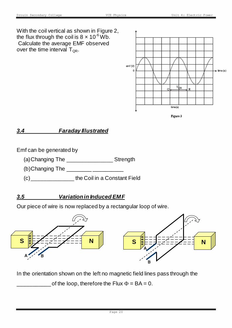
With the coil vertical as shown in Figure 2, the flux through the coil is 8 × 10⁻⁶ Wb. Calculate the average EMF observed over the time interval TQR. 3.4 Faraday Illustrated Emf can be generated by
(a) Changing The _______________ Strength
(b) Changing The ________ __________
(c) ______________ the Coil in a Constant Field
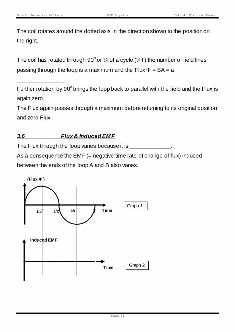
3.5 Variation in Induced EMF Our piece of wire is now replaced by a rectangular loop of wire.
In the orientation shown on the left no magnetic field lines pass through the
___________ of the loop, therefore the Flux Φ = BA = 0.
A B
S N A
B
S N
Drouin Secondary College VCE Physics Unit 4: Electric Power
Page 21
The coil rotates around the dotted axis in the direction shown to the position on
the right.
The coil has rotated through 90o or ¼ of a cycle (¼T) the number of field lines
passing through the loop is a maximum and the Flux Φ = BA = a
_______________.
Further rotation by 90o brings the loop back to parallel with the field and the Flux is
again zero.
The Flux again passes through a maximum before returning to its original position
and zero Flux.
3.6 Flux & Induced EMF The Flux through the loop varies because it is _____________.
As a consequence the EMF (= negative time rate of change of flux) induced
between the ends of the loop A and B also varies.
Time
(Flux Φ ) Graph
Time
Induced EMF
Graph
3/4
1/4T 1/2
T
3/4
1/4
1/2
T
Graph 1
Graph 2
Drouin Secondary College VCE Physics Unit 4: Electric Power
Page 22
3.7 Another View of Variation in Induced EMF As the rectangular loop rotates, the Flux through it varies in a sinusoidal manner
as shown in Graph 1.
The Induced EMF is dependent upon the “time rate of change” of the flux through
the loop, ie. (Φ∆/∆t).
Another way of saying this is the Induced EMF is calculated from the differential of
Flux with respect to time.
Since the Flux is a Sine type relation the Induced EMF will be a Cosine type
relation, (the differential of a Sine term is Cosine term).
Thus, a graph of the Induced EMF will be as shown in Graph 2
N.B. The Induced EMF is only generated while the amount of Flux through the
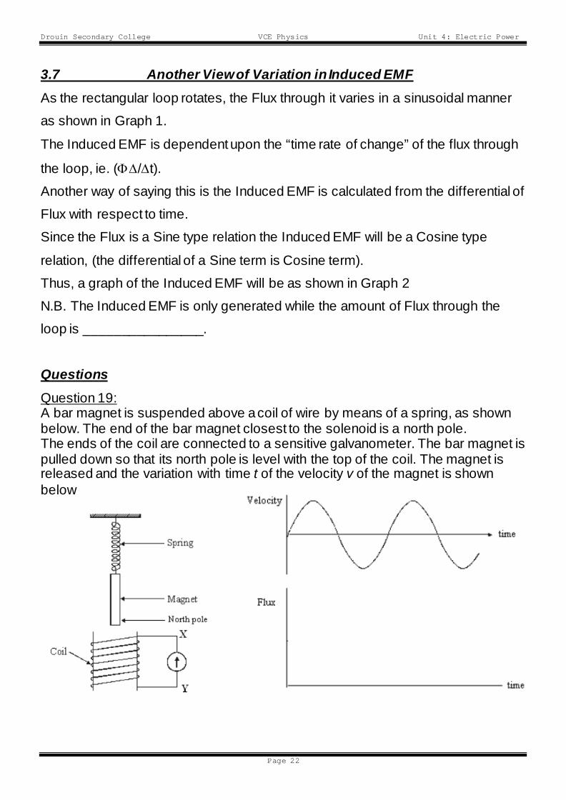
loop is ________________. Questions Question 19: A bar magnet is suspended above a coil of wire by means of a spring, as shown below. The end of the bar magnet closest to the solenoid is a north pole. The ends of the coil are connected to a sensitive galvanometer. The bar magnet is pulled down so that its north pole is level with the top of the coil. The magnet is released and the variation with time t of the velocity v of the magnet is shown below
Drouin Secondary College VCE Physics Unit 4: Electric Power
Page 23
On the axes provided, draw a flux – time graph for the flux measured at the top of the coil (the point of release of the magnet)
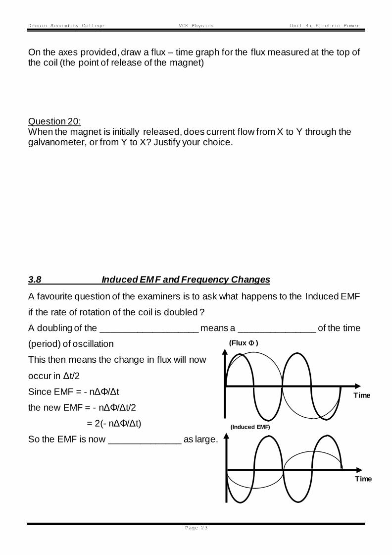
Question 20: When the magnet is initially released, does current flow from X to Y through the galvanometer, or from Y to X? Justify your choice. 3.8 Induced EMF and Frequency Changes
A favourite question of the examiners is to ask what happens to the Induced EMF
if the rate of rotation of the coil is doubled ?
A doubling of the ___________________ means a _______________ of the time
(period) of oscillation
This then means the change in flux will now
occur in Δt/2
Since EMF = - nΔΦ/Δt
the new EMF = - nΔΦ/Δt/2
= 2(- nΔΦ/Δt)
So the EMF is now ______________ as large.
Time
(Flux Φ ) Graph
Time
(Induced EMF)
Graph
Drouin Secondary College VCE Physics Unit 4: Electric Power
Page 24
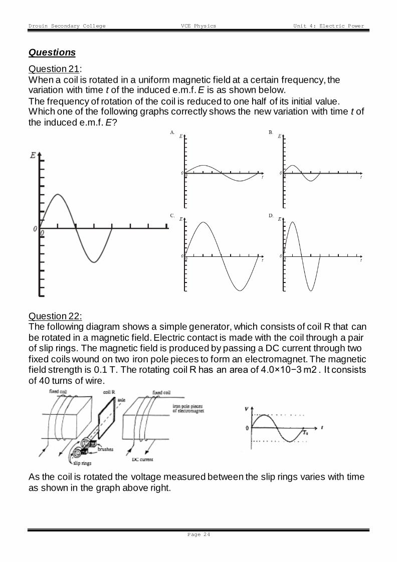
Questions Question 21: When a coil is rotated in a uniform magnetic field at a certain frequency, the variation with time t of the induced e.m.f. E is as shown below. The frequency of rotation of the coil is reduced to one half of its initial value. Which one of the following graphs correctly shows the new variation with time t of the induced e.m.f. E?
Question 22: The following diagram shows a simple generator, which consists of coil R that can be rotated in a magnetic field. Electric contact is made with the coil through a pair of slip rings. The magnetic field is produced by passing a DC current through two fixed coils wound on two iron pole pieces to form an electromagnet. The magnetic field strength is 0.1 T. The rotating coil R has an area of 4.0×10⁻³ m2 . It consists of 40 turns of wire.
As the coil is rotated the voltage measured between the slip rings varies with time as shown in the graph above right.
Drouin Secondary College VCE Physics Unit 4: Electric Power
Page 25
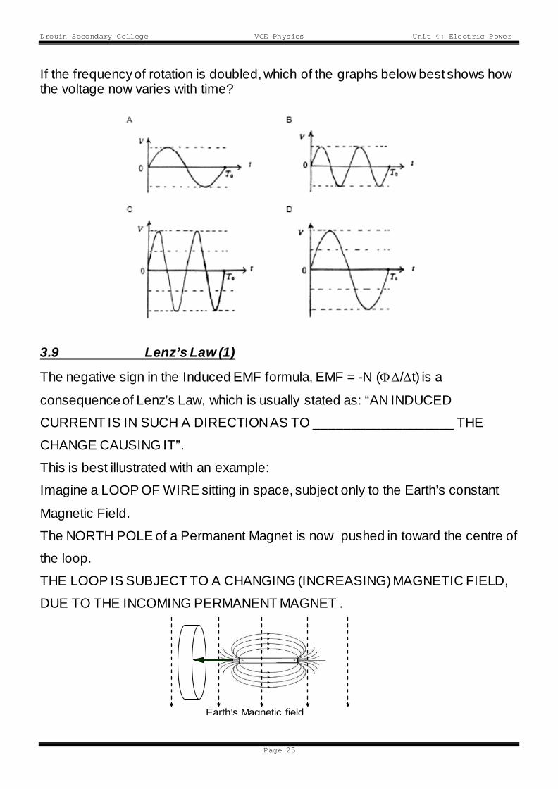
If the frequency of rotation is doubled, which of the graphs below best shows how the voltage now varies with time? 3.9 Lenz’s Law (1)
The negative sign in the Induced EMF formula, EMF = -N (Φ∆/∆t) is a
consequence of Lenz’s Law, which is usually stated as: “AN INDUCED
CURRENT IS IN SUCH A DIRECTION AS TO ___________________ THE
CHANGE CAUSING IT”.
This is best illustrated with an example:
Imagine a LOOP OF WIRE sitting in space, subject only to the Earth’s constant
Magnetic Field.
The NORTH POLE of a Permanent Magnet is now pushed in toward the centre of
the loop.
THE LOOP IS SUBJECT TO A CHANGING (INCREASING) MAGNETIC FIELD,
DUE TO THE INCOMING PERMANENT MAGNET .
Earth’s Magnetic field
Drouin Secondary College VCE Physics Unit 4: Electric Power
Page 26
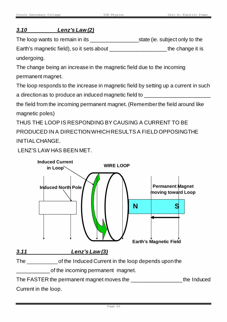
3.10 Lenz’s Law (2) The loop wants to remain in its ________________state (ie. subject only to the
Earth’s magnetic field), so it sets about ___________________ the change it is
undergoing.
The change being an increase in the magnetic field due to the incoming
permanent magnet.
The loop responds to the increase in magnetic field by setting up a current in such
a direction as to produce an induced magnetic field to ______________________
the field from the incoming permanent magnet. (Remember the field around like
magnetic poles)
THUS THE LOOP IS RESPONDING BY CAUSING A CURRENT TO BE
PRODUCED IN A DIRECTION WHICH RESULTS A FIELD OPPOSINGTHE
INITIAL CHANGE.
LENZ’S LAW HAS BEEN MET.
3.11 Lenz’s Law (3) The __________ of the Induced Current in the loop depends upon the
___________ of the incoming permanent magnet.
The FASTER the permanent magnet moves the _________________ the Induced
Current in the loop.
Permanent Magnet moving toward Loop
N S
Induced Current in Loop
Induced North Pole
WIRE LOOP
Earth’s Magnetic Field
Drouin Secondary College VCE Physics Unit 4: Electric Power
Page 27
Lenz’s Law is really a restatement of the Law of Conservation of Energy.
Consider the following:
The induced current gives rise to an Induced Magnetic Field and thus to the Flux
threading the loop.
If this Induced Flux ADDED to the flux due to the incoming permanent magnet,
Total Flux would rise producing a larger induced current which in turn would
increase the Flux through the loop producing a larger current
producing a larger Flux producing a larger current etc. etc. etc. and all this without
expending any energy at all…………
This is an untenable situation, and would, and could, not occur in nature.
YOU GET NOTHING FOR NOTHING IN THIS WORLD.
Thus, the induced current MUST be in such a direction as to produce a flux to
oppose the flux of the incoming permanent magnet in order to meet the
Conservation of Energy requirement.
THE WORK DONE IN PUSHING THE PERMANENT MAGNET INTO THE LOOP
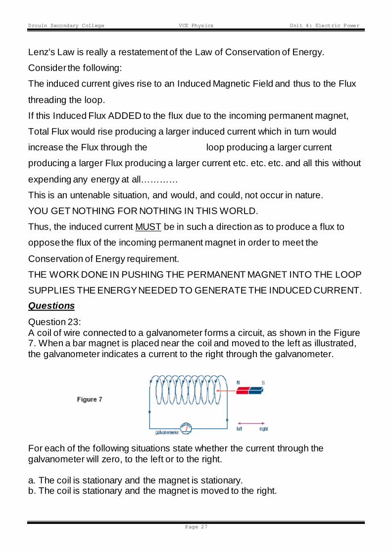
SUPPLIES THE ENERGY NEEDED TO GENERATE THE INDUCED CURRENT. Questions Question 23: A coil of wire connected to a galvanometer forms a circuit, as shown in the Figure 7. When a bar magnet is placed near the coil and moved to the left as illustrated, the galvanometer indicates a current to the right through the galvanometer.
For each of the following situations state whether the current through the galvanometer will zero, to the left or to the right. a. The coil is stationary and the magnet is stationary. b. The coil is stationary and the magnet is moved to the right.
Drouin Secondary College VCE Physics Unit 4: Electric Power
Page 28
c. The coil is moved to the right and the magnet is stationary. d. The coil is moved to the left and the magnet is stationary.
Chapter 4
4.0 Simple DC Motors
Simple Direct Current (DC) Electric Motors consist of:
(a) A rotating or spinning coil of wires called a ______________
b) A stationary magnet (either permanent or electromagnet) called the
____________.
In Motors, Electrical Energy is supplied from an outside source and Mechanical
Energy in the form of rotation is extracted.
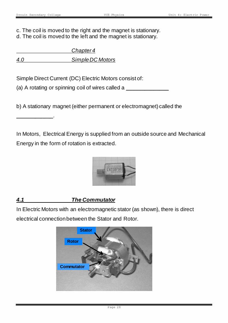
4.1 The Commutator In Electric Motors with an electromagnetic stator (as shown), there is direct
electrical connection between the Stator and Rotor.
Stator Rotor
Commutator
Drouin Secondary College VCE Physics Unit 4: Electric Power
Page 29
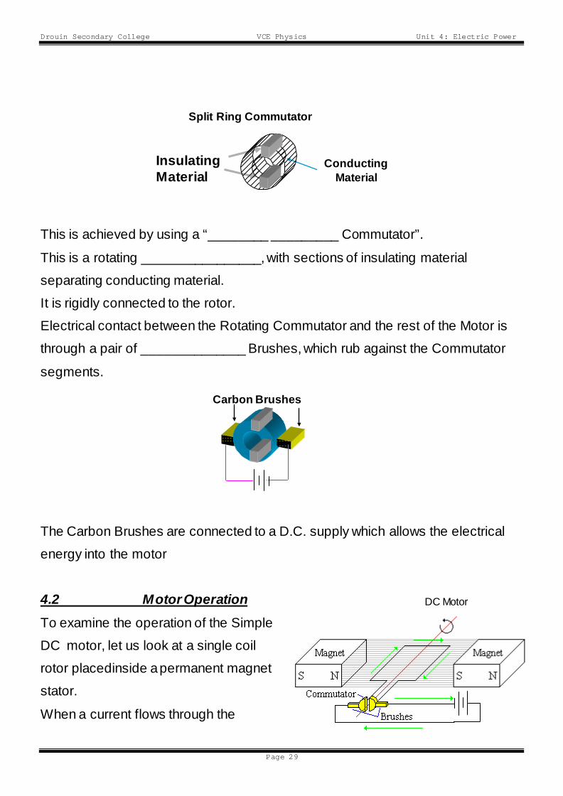
This is achieved by using a “________ _________ Commutator”.
This is a rotating ________________, with sections of insulating material
separating conducting material.
It is rigidly connected to the rotor.
Electrical contact between the Rotating Commutator and the rest of the Motor is
through a pair of ______________ Brushes, which rub against the Commutator
segments.
The Carbon Brushes are connected to a D.C. supply which allows the electrical
energy into the motor
4.2 Motor Operation To examine the operation of the Simple
DC motor, let us look at a single coil
rotor placedinside a permanent magnet
stator.
When a current flows through the
Conducting Material
Insulating Material
Split Ring Commutator
Carbon Brushes
DC Motor

Drouin Secondary College VCE Physics Unit 4: Electric Power
Page 30
Brushes and Commutator into the Rotor, the sides of the coil each experience a
Force - (FMAG).
The direction of the force is found using the
Right Hand Palm Rule.
Under the action of FMAG the coil rotates until it reaches the vertical orientation.
At this point the insulating material in the commutator cuts off the current to the
loop.
As the loop is moving, it has inertia, which will carry it past the vertical at which
point the current will again flow, but in the _______________ direction
FMAG acts to continue rotation in the same direction. The Commutator maintains
the current flow in the same direction in the rotor coil, so it always rotates in the
same direction. Questions
Question 24:
Figure 4 shows a schematic diagram of a DC motor.
The motor is initially stationary as shown in Figure 4.
In which direction, A (clockwise) or B (anticlockwise), will the motor rotate when
the switch is closed?
Drouin Secondary College VCE Physics Unit 4: Electric Power
Page 31
Question 25:
Explain your answer.
Question 26:
Why is the split ring commutator necessary for the motor to operate correctly? Explain the operation of the commutator.
4.3 Electric Motors & Generators • Electric Motors and Electric Generators are the ___________ DEVICE but
operated in different ways.
• Both consist of:
(a) A rotating or spinning coil of wires called a ROTOR
(b) A stationary magnet (either permanent or electromagnet) called the
STATOR.
When the device is operated as a MOTOR, Electrical _________ is supplied from
an outside source and ___________________________ Energy in the form of
rotation is extracted.
When operated as a GENERATOR, Mechanical Energy is supplied from an
outside source and Electrical Energy is ________________________.
Drouin Secondary College VCE Physics Unit 4: Electric Power
Page 32
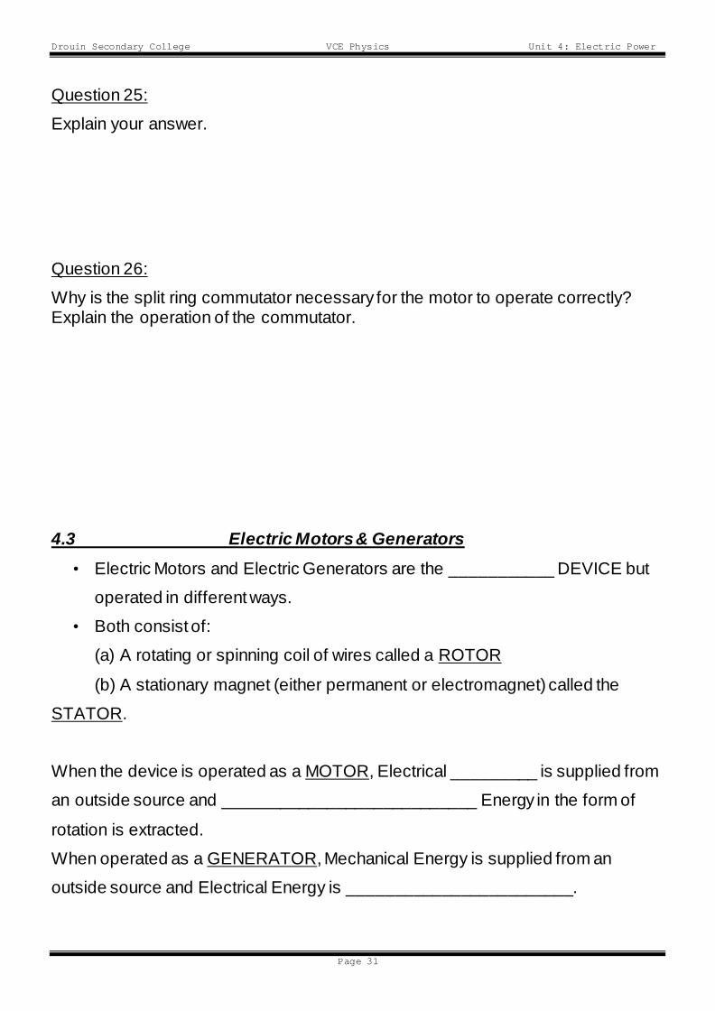
4.4 The Commutator - Generators When part of a Generating System, the _____
_________ Commutator is used to extract
Electrical Energy from the rotor which is being
spun by an external force.
At T = 0, in the orientation shown, the
generated EMF is at its maximum value.
In the next ¼ cycle (or 90o) the EMF generated will have fallen to 0.
Between t = ¼T and t = ½T, the EMF rises to it maximum value.
As the coil continues to rotate the EMF continues to rise and fall as shown
Thus, the output from the Split Ring Commutator is a Pulsating D.C. (Direct
Current) signal as shown on the graph.
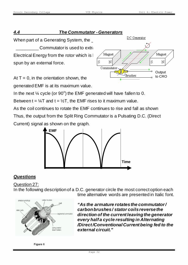
Questions Question 27: In the following description of a D.C. generator circle the most correct option each
time alternative words are presented in Italic font. “As the armature rotates the commutator / carbon brushes / stator coils reverse the direction of the current leaving the generator every half a cycle resulting in Alternating /Direct /Conventional Current being fed to the external circuit.”
Time
EMF
1/4T 1/2T 3/4T 0 T
Output to CRO
Drouin Secondary College VCE Physics Unit 4: Electric Power
Page 33
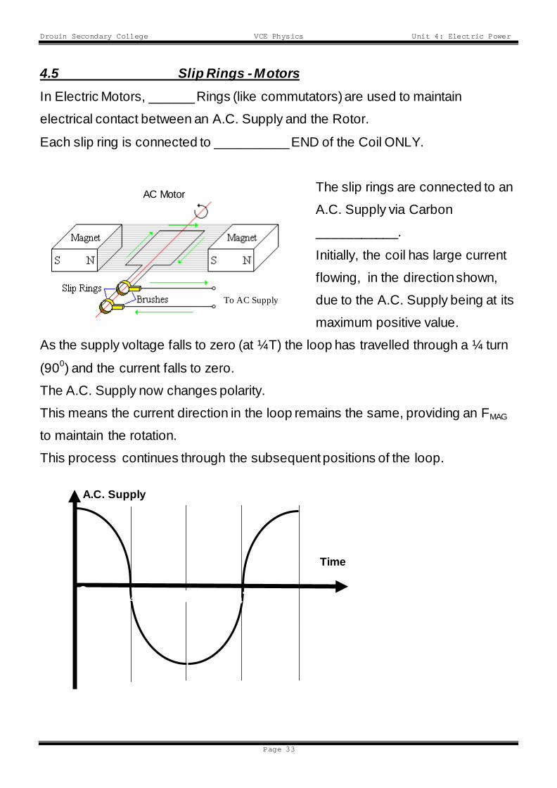
4.5 Slip Rings - Motors In Electric Motors, ______ Rings (like commutators) are used to maintain
electrical contact between an A.C. Supply and the Rotor.
Each slip ring is connected to __________ END of the Coil ONLY.
The slip rings are connected to an
A.C. Supply via Carbon
___________.
Initially, the coil has large current
flowing, in the direction shown,
due to the A.C. Supply being at its
maximum positive value.
As the supply voltage falls to zero (at ¼T) the loop has travelled through a ¼ turn
(900) and the current falls to zero.
The A.C. Supply now changes polarity.
This means the current direction in the loop remains the same, providing an FMAG
to maintain the rotation.
This process continues through the subsequent positions of the loop.
Time
A.C. Supply
0 1/4T 1/2T 3/4T T
AC Generator
To AC Supply
AC Motor
Drouin Secondary College VCE Physics Unit 4: Electric Power
Page 34
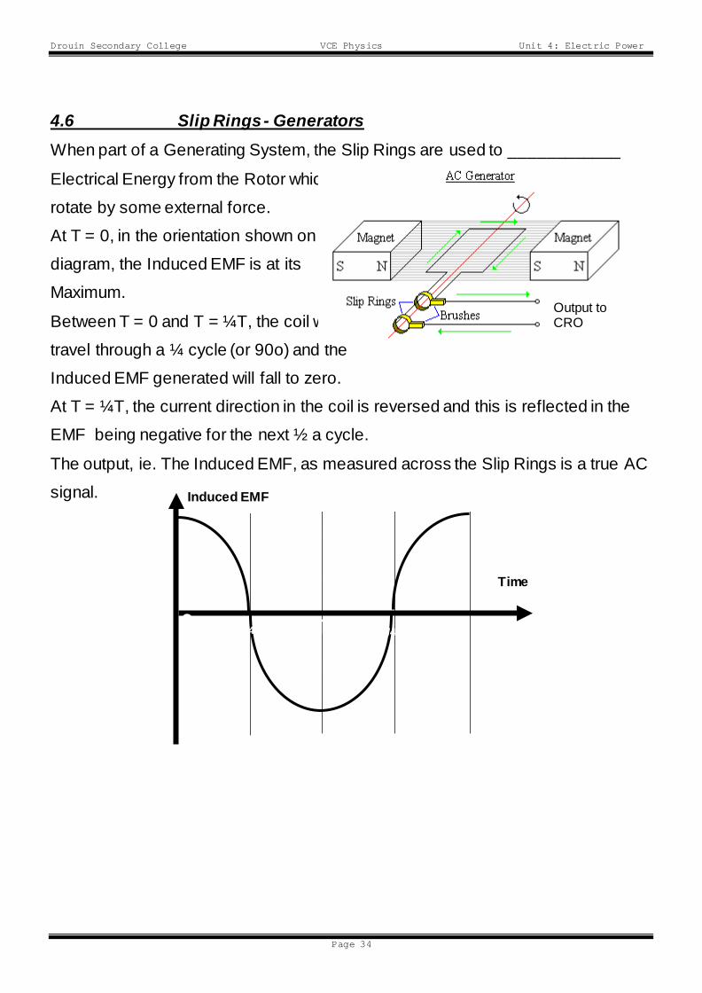
4.6 Slip Rings - Generators When part of a Generating System, the Slip Rings are used to ____________
Electrical Energy from the Rotor which is being forced to
rotate by some external force.
At T = 0, in the orientation shown on the
diagram, the Induced EMF is at its
Maximum.
Between T = 0 and T = ¼T, the coil will
travel through a ¼ cycle (or 90o) and the
Induced EMF generated will fall to zero.
At T = ¼T, the current direction in the coil is reversed and this is reflected in the
EMF being negative for the next ½ a cycle.
The output, ie. The Induced EMF, as measured across the Slip Rings is a true AC
signal.
Time
Induced EMF
0 1/4T 1/2T 3/4T T
Output to CRO
Drouin Secondary College VCE Physics Unit 4: Electric Power
Page 35
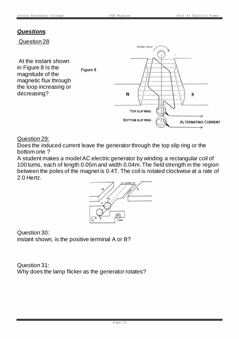
Questions Question 28
At the instant shown in Figure 8 Is the magnitude of the magnetic flux through the loop increasing or decreasing? Question 29: Does the induced current leave the generator through the top slip ring or the bottom one ? A student makes a model AC electric generator by winding a rectangular coil of 100 turns, each of length 0.05m and width 0.04m. The field strength in the region between the poles of the magnet is 0.4T. The coil is rotated clockwise at a rate of 2.0 Hertz. Question 30: instant shown, is the positive terminal A or B? Question 31: Why does the lamp flicker as the generator rotates?
Drouin Secondary College VCE Physics Unit 4: Electric Power
Page 36
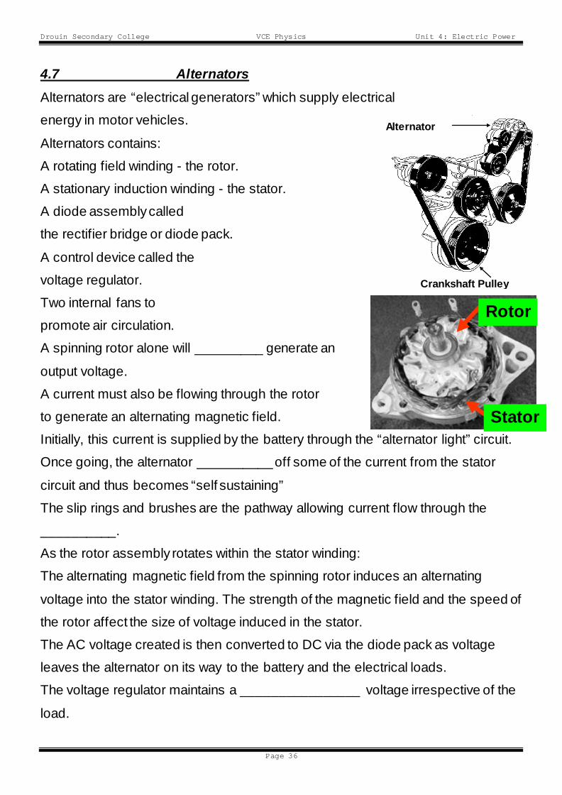
4.7 Alternators Alternators are “electrical generators” which supply electrical
energy in motor vehicles.
Alternators contains:
A rotating field winding - the rotor.
A stationary induction winding - the stator.
A diode assembly called
the rectifier bridge or diode pack.
A control device called the
voltage regulator.
Two internal fans to
promote air circulation.
A spinning rotor alone will _________ generate an
output voltage.
A current must also be flowing through the rotor
to generate an alternating magnetic field.
Initially, this current is supplied by the battery through the “alternator light” circuit.
Once going, the alternator __________ off some of the current from the stator
circuit and thus becomes “self sustaining”
The slip rings and brushes are the pathway allowing current flow through the
__________.
As the rotor assembly rotates within the stator winding:
The alternating magnetic field from the spinning rotor induces an alternating
voltage into the stator winding. The strength of the magnetic field and the speed of
the rotor affect the size of voltage induced in the stator.
The AC voltage created is then converted to DC via the diode pack as voltage
leaves the alternator on its way to the battery and the electrical loads.
The voltage regulator maintains a ________________ voltage irrespective of the
load.
Alternator
Crankshaft Pulley
Rotor
Stator
Drouin Secondary College VCE Physics Unit 4: Electric Power
Page 37
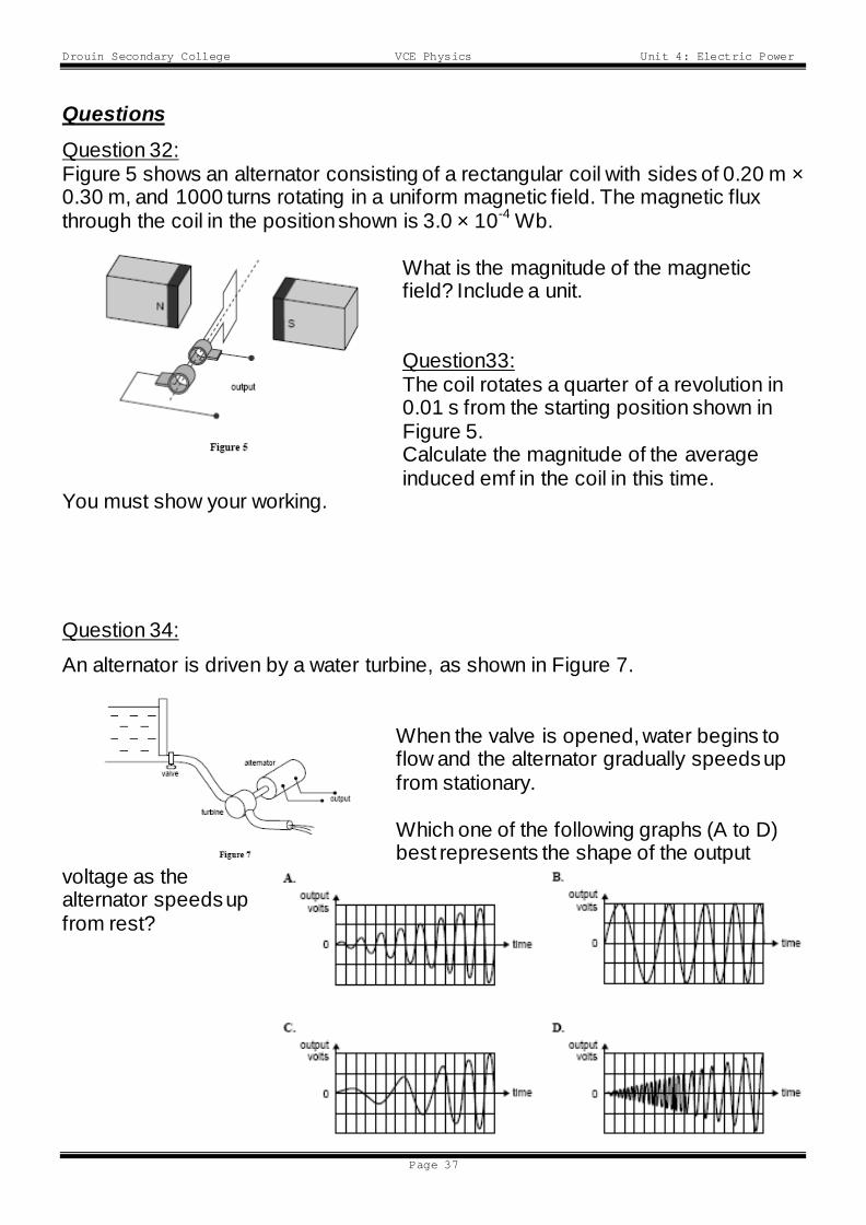
Questions Question 32: Figure 5 shows an alternator consisting of a rectangular coil with sides of 0.20 m × 0.30 m, and 1000 turns rotating in a uniform magnetic field. The magnetic flux through the coil in the position shown is 3.0 × 10⁻⁴ Wb.
What is the magnitude of the magnetic field? Include a unit. Question33: The coil rotates a quarter of a revolution in 0.01 s from the starting position shown in Figure 5. Calculate the magnitude of the average induced emf in the coil in this time.
You must show your working.
Question 34:
An alternator is driven by a water turbine, as shown in Figure 7.
When the valve is opened, water begins to flow and the alternator gradually speeds up from stationary. Which one of the following graphs (A to D) best represents the shape of the output
voltage as the alternator speeds up from rest?
Drouin Secondary College VCE Physics Unit 4: Electric Power
Page 38
Chapter 5 5.0 Transformers
Transformers are devices which are capable of __________________ or
____________________ the voltage of (and thus the current available from) an
input signal.
Transformers consist of 2 separate coils of wire (called “________________”)
held close together and usually wrapped around a “soft iron” core (which is highly
susceptible to magnetisation).
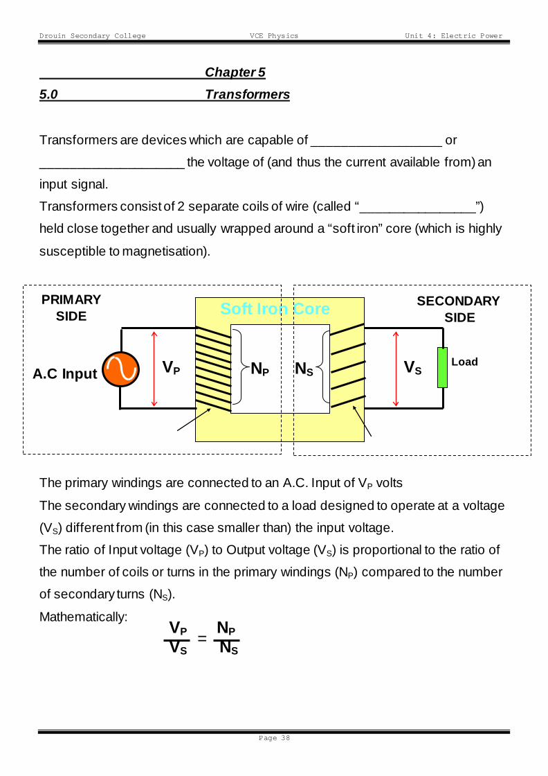
The primary windings are connected to an A.C. Input of VP volts
The secondary windings are connected to a load designed to operate at a voltage
(VS) different from (in this case smaller than) the input voltage.
The ratio of Input voltage (VP) to Output voltage (VS) is proportional to the ratio of
the number of coils or turns in the primary windings (NP) compared to the number
of secondary turns (NS).
Mathematically:
VP
Soft Iron Core
VS Load NP A.C Input
PRIMARY SIDE
Primary Windings
SECONDARY SIDE
Secondary Windings
NS
VP NP VS NS
=

Drouin Secondary College VCE Physics Unit 4: Electric Power
Page 39
5.1 Transformer Operation Transformers rely on the principal of Electromagnetic _________________ for
their operation.
The A.C. Supply forces a current through the primary winding, creating an
associated magnetic field.
As the Voltage of the supply increases a larger current flows in the primary
winding, generating a stronger magnetic field.
This _________________ Magnetic Field induces a current to flow secondary
winding and hence through the circuit connected to it.
As the polarity of the Supply reverses the same process occurs with the current
and magnetic field, again inducing a current in the secondary circuit but this time
in the opposite direction.
Electromagnetic Induction only occurs when _________________ (in current or
magnetic field) are occurring.
The A.C. supply is producing these __________________ constantly, thus the
transformer will operate satisfactorily.
TRANSFORMERS CAN ONLY OPERATE UNDER A.C. CONDITIONS.
5.2 Transformer Types The relationship between Voltage and the Number of Turns in the primary and
secondary sides has already been defined as: Vp/Vs = Np/Ns
Drouin Secondary College VCE Physics Unit 4: Electric Power
Page 40
Ideal Transformers suffer no losses across the transformer thus:
Power delivered to the primary side ___________ Power generated in the
secondary side.
Mathematically:
Pp = Ps
thus: VpIp = VsIs
Combining all formulae we get:
Vp/Vs = Np/Ns = Is/Ip
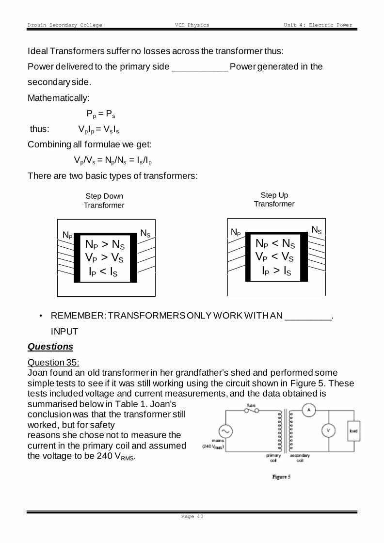
There are two basic types of transformers:
• REMEMBER: TRANSFORMERS ONLY WORK WITH AN _________.
INPUT Questions Question 35: Joan found an old transformer in her grandfather’s shed and performed some simple tests to see if it was still working using the circuit shown in Figure 5. These tests included voltage and current measurements, and the data obtained is summarised below in Table 1. Joan’s conclusion was that the transformer still worked, but for safety reasons she chose not to measure the current in the primary coil and assumed the voltage to be 240 VRMS.
VP VS
NP NS
NP > NS VP > VS
IP < IS
Step Down Transformer
VP VS
NP
NP < NS VP < VS
IP > IS
Step Up Transformer
NS
Drouin Secondary College VCE Physics Unit 4: Electric Power
Page 41
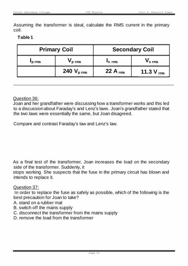
Assuming the transformer is ideal, calculate the RMS current in the primary coil.
Question 36: Joan and her grandfather were discussing how a transformer works and this led to a discussion about Faraday’s and Lenz’s laws. Joan’s grandfather stated that the two laws were essentially the same, but Joan disagreed. Compare and contrast Faraday’s law and Lenz’s law. As a final test of the transformer, Joan increases the load on the secondary side of the transformer. Suddenly, it stops working. She suspects that the fuse in the primary circuit has blown and intends to replace it. Question 37: In order to replace the fuse as safely as possible, which of the following is the best precaution for Joan to take? A. stand on a rubber mat B. switch off the mains supply C. disconnect the transformer from the mains supply D. remove the load from the transformer
Primary Coil Secondary Coil
Table 1
Ip rms Vp rms Is rms Vs rms
240 Vp rms 22 A rms 11.3 V rms
Drouin Secondary College VCE Physics Unit 4: Electric Power
Page 42
6.3 A.C. Electricity
There are two basic types of current electricity:
(a) D.C. (Direct Current) electricity where the current flows in one direction only.
(b) A.C. (Alternating Current) where the current changes ________________ in
a regular and periodic fashion.
The Electricity Grid supplies domestic and industrial users with A.C. electricity.
A.C. is favoured because:
it is cheap and easy to generate
it can be “transformed”; its voltage can be raised or lowered at will by passage
through a transformer.
The only large scale use of high voltage D.C. electricity is in public transport,
i.e. trams and trains.
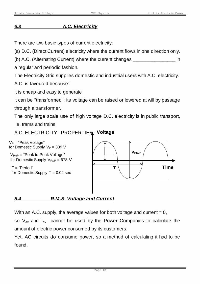
A.C. ELECTRICITY - PROPERTIES
5.4 R.M.S. Voltage and Current
With an A.C. supply, the average values for both voltage and current = 0,
so Vav and Iav cannot be used by the Power Companies to calculate the
amount of electric power consumed by its customers.
Yet, AC circuits do consume power, so a method of calculating it had to be
found.
Voltage
Time
VPtoP
T
VP = “Peak Voltage” for Domestic Supply VP = 339 V
VPtoP = “Peak to Peak Voltage” for Domestic Supply VPtoP = 678 V
T = “Period” for Domestic Supply T = 0.02 sec
Drouin Secondary College VCE Physics Unit 4: Electric Power
Page 43
To get around this problem R.M.S. or _______ ________ _________ values
for AC voltage and current were developed.
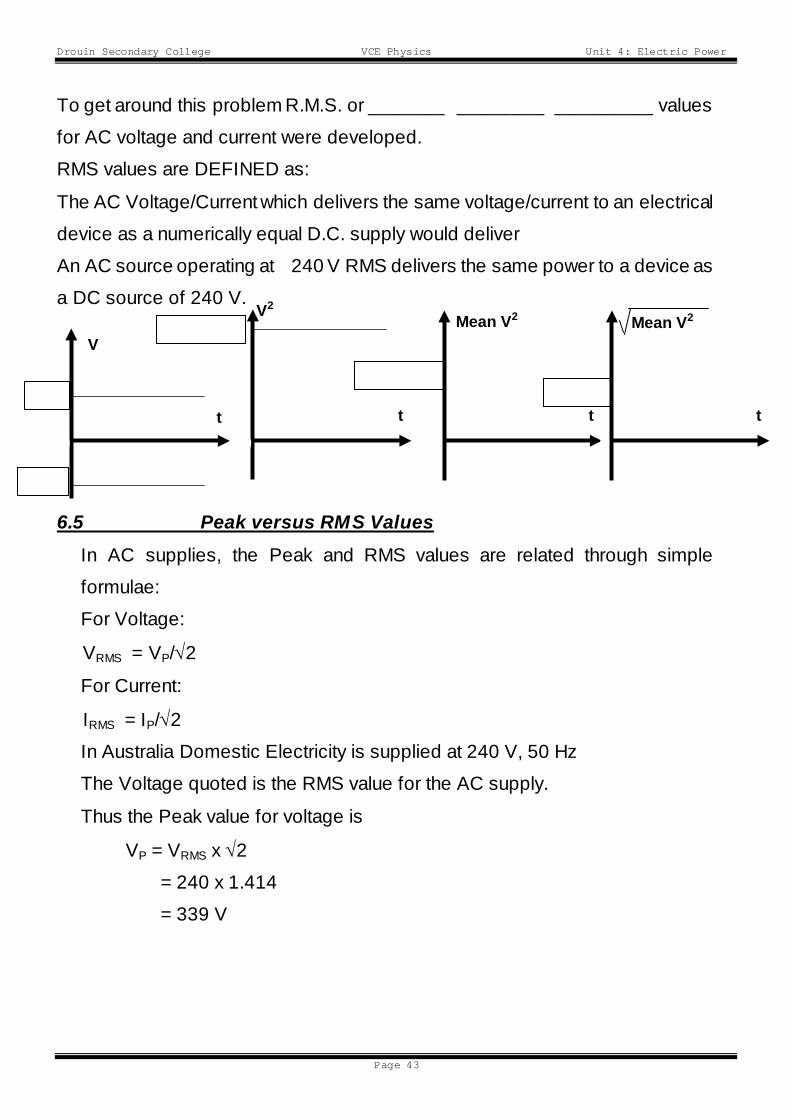
RMS values are DEFINED as:
The AC Voltage/Current which delivers the same voltage/current to an electrical
device as a numerically equal D.C. supply would deliver
An AC source operating at 240 V RMS delivers the same power to a device as
a DC source of 240 V.
6.5 Peak versus RMS Values In AC supplies, the Peak and RMS values are related through simple
formulae:
For Voltage:
VRMS = VP/√2
For Current:
IRMS = IP/√2
In Australia Domestic Electricity is supplied at 240 V, 50 Hz
The Voltage quoted is the RMS value for the AC supply.
Thus the Peak value for voltage is
VP = VRMS x √2
= 240 x 1.414
= 339 V
t 33
-
0
V2
t
339
0
Mean V2
t
339
0
Mean V2
t 339
0
V
Drouin Secondary College VCE Physics Unit 4: Electric Power
Page 44
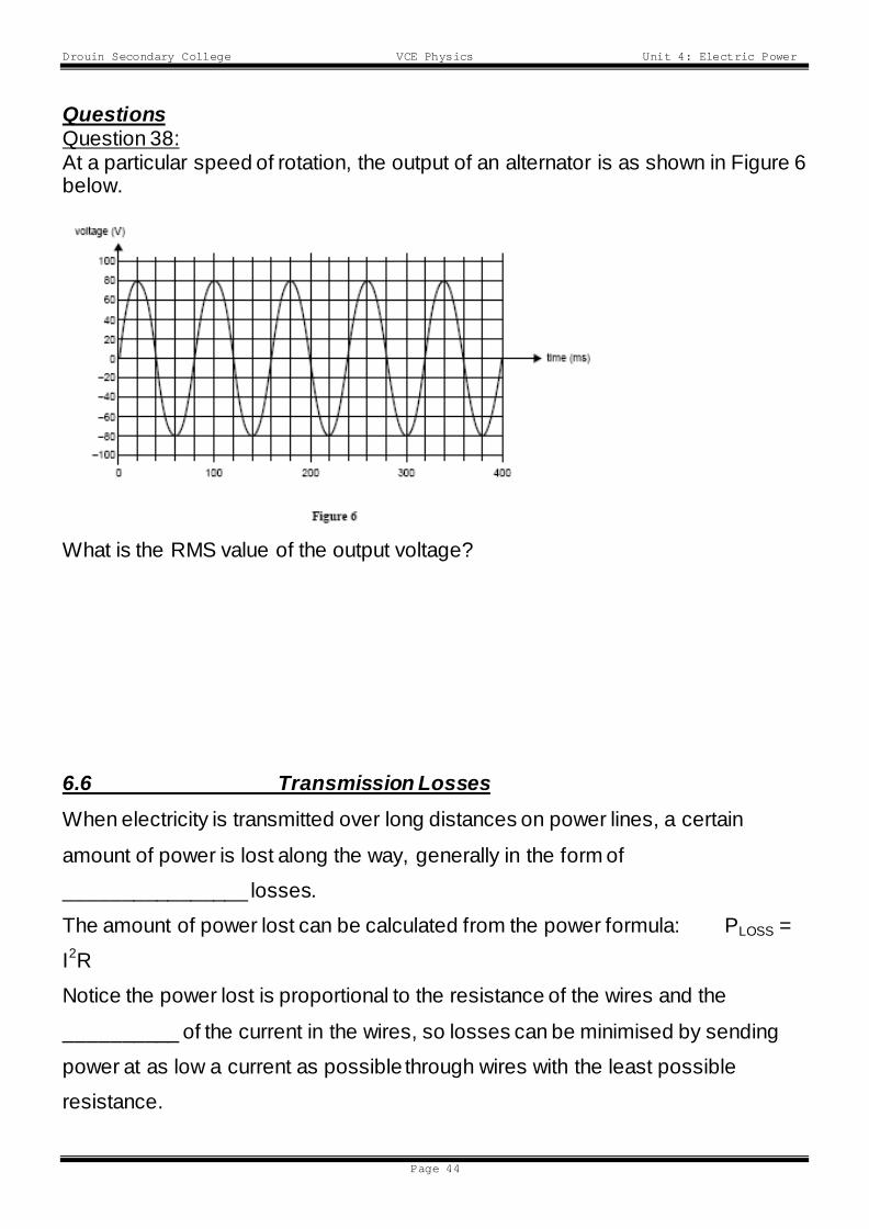
Questions Question 38: At a particular speed of rotation, the output of an alternator is as shown in Figure 6 below.
What is the RMS value of the output voltage? 6.6 Transmission Losses When electricity is transmitted over long distances on power lines, a certain
amount of power is lost along the way, generally in the form of
________________ losses.
The amount of power lost can be calculated from the power formula: PLOSS =
I2R
Notice the power lost is proportional to the resistance of the wires and the
__________ of the current in the wires, so losses can be minimised by sending
power at as low a current as possible through wires with the least possible
resistance.
Drouin Secondary College VCE Physics Unit 4: Electric Power
Page 45
Because Power is also the product of V and I ; (P = VI), a ______ current
necessarily means a _____________ voltage to deliver the same amount of
power.
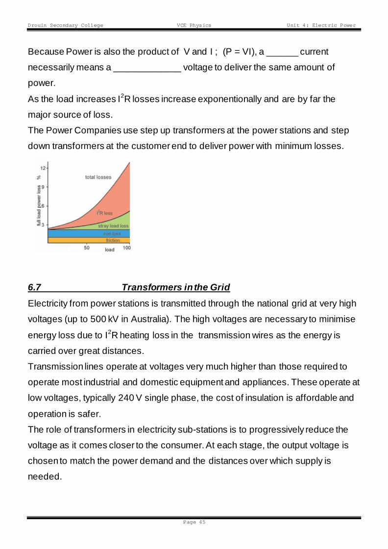
As the load increases I2R losses increase exponentionally and are by far the
major source of loss.
The Power Companies use step up transformers at the power stations and step
down transformers at the customer end to deliver power with minimum losses.
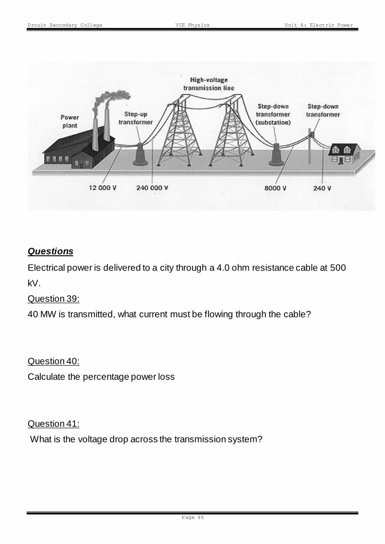
6.7 Transformers in the Grid Electricity from power stations is transmitted through the national grid at very high
voltages (up to 500 kV in Australia). The high voltages are necessary to minimise
energy loss due to I2R heating loss in the transmission wires as the energy is
carried over great distances.
Transmission lines operate at voltages very much higher than those required to
operate most industrial and domestic equipment and appliances. These operate at
low voltages, typically 240 V single phase, the cost of insulation is affordable and
operation is safer.
The role of transformers in electricity sub-stations is to progressively reduce the
voltage as it comes closer to the consumer. At each stage, the output voltage is
chosen to match the power demand and the distances over which supply is
needed.
Drouin Secondary College VCE Physics Unit 4: Electric Power
Page 46
Questions
Electrical power is delivered to a city through a 4.0 ohm resistance cable at 500
kV.
Question 39:
40 MW is transmitted, what current must be flowing through the cable?
Question 40:
Calculate the percentage power loss
Question 41:
What is the voltage drop across the transmission system?
Drouin Secondary College VCE Physics Unit 4: Electric Power
Page 47
Question 42:
Explain why it is advantageous to transmit at a very high voltage
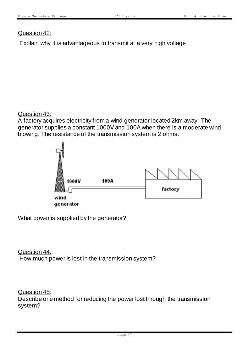
Question 43: A factory acquires electricity from a wind generator located 2km away. The generator supplies a constant 1000V and 100A when there is a moderate wind blowing. The resistance of the transmission system is 2 ohms.
What power is supplied by the generator? Question 44: How much power is lost in the transmission system? Question 45: Describe one method for reducing the power lost through the transmission system?
Drouin Secondary College VCE Physics Unit 4: Electric Power
Page 48
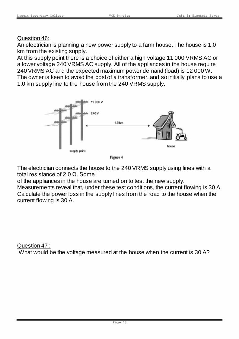
Question 46: An electrician is planning a new power supply to a farm house. The house is 1.0 km from the existing supply. At this supply point there is a choice of either a high voltage 11 000 VRMS AC or a lower voltage 240 VRMS AC supply. All of the appliances in the house require 240 VRMS AC and the expected maximum power demand (load) is 12 000 W. The owner is keen to avoid the cost of a transformer, and so initially plans to use a 1.0 km supply line to the house from the 240 VRMS supply.
The electrician connects the house to the 240 VRMS supply using lines with a total resistance of 2.0 Ω. Some of the appliances in the house are turned on to test the new supply. Measurements reveal that, under these test conditions, the current flowing is 30 A. Calculate the power loss in the supply lines from the road to the house when the current flowing is 30 A. Question 47 : What would be the voltage measured at the house when the current is 30 A?
Drouin Secondary College VCE Physics Unit 4: Electric Power
Page 49
Question 48: The electrician suggests that using the 11 000 VRMS supply with a step-down transformer at the house could deliver the same amount of power to the house, with a significant reduction in the power loss in the supply lines. Comment