vector - brunswick bowling · vector centor network system pre-installation manual ... output...
TRANSCRIPT

Pre-Installation Manual
Vector
Center Network SystemOctober 2013 / 10-095400-048
2 Vector Center Network System Pre-Installation
Vector Centor Network System Pre-Installation Manual
© October 2013 by the Brunswick Bowling and Billiards Corporation. All rights reserved.
Manual Part No. 10-095400-048
Notice: If available, updates to this manual can be found on-line at www.brunswickbowling.com.
Confidential proprietary information. All information contained in this document is subject to change without notice.
Brunswick Bowling & Billiards Corporation525 West Laketon AvenueP.O. Box 329Muskegon, MI 49443-0329U.S.A.
231.725.3300

Vector Center Network System Pre-Installation 3
SafetyThroughout this publication, “Warnings”, and “Cautions” (accompanied by one of the International HAZARD Symbols) are used to alert the mechanic to special instructions concerning a particular service or operation that may be hazardous if performed incorrectly or carelessly. They are defined below. OBSERVE AND READ THEM CAREFULLY!
These “Safety Alerts” alone cannot eliminate the hazards that they signal. Strict compliance to these special instructions when performing the service, plus training and “Common Sense” operation are major accident prevention measures.
NOTE or IMPORTANT!: Willdesignatesignificantinformationalnotes.
WARNING! Will designate a mechanical or nonelectrical alert which could potentially
cause personal injury or death.
WARNING! Will designate electrical alerts which could potentially cause personal injury or
death.
CAUTION! Will designate an alert which could potentially cause product damage.
Will designate grounding alerts.

4 Vector Center Network System Pre-Installation
CoNteNtSOverview ...................................................................................................................................6
Bowler’s touchscreen ........................................................................................................................6Bowler’s keypad ...............................................................................................................................6Safety Notice to Users of this Manual ................................................................................................Vector and Vector Plus ......................................................................................................................7
Preliminary Survey ..................................................................................................................8Building Configuration .....................................................................................................................8
Lane Configuration .........................................................................................................................8Phase and Voltage ...........................................................................................................................8Existing Equipment ........................................................................................................................8
New Equipment ................................................................................................................................9Distances .........................................................................................................................................10
Ceiling Height and Type of Ceiling .............................................................................................10Ethernet .......................................................................................................................................10Intercom .......................................................................................................................................11
Audio/Video ....................................................................................................................................11Vector Scoring Installation Schedule ..................................................................................12
Customer Responsibility .................................................................................................................12Installation Schedule .......................................................................................................................13
To Be Performed By Certified Field Mechanic ............................................................................13To Be Performed By Brunswick Field Engineer ..........................................................................13To Be Performed By Brunswick Field Trainer .............................................................................14
Important ................................................................................................................................15Surge Suppression ...........................................................................................................................15Brunswick’s Responsibility .............................................................................................................15Power Conditioning ........................................................................................................................15Warning ...........................................................................................................................................15Isolated Ground Receptacles - NEC 250-74 Exception 4 ...............................................................16Grounding Conductor - NEC 384-27 ..............................................................................................16Extended Power Outage ..................................................................................................................16Carpeting in Bowlers’ Area .............................................................................................................16Carpeting in Electronics Areas ........................................................................................................16Atmospheric Conditions .................................................................................................................16
Electrical Overview ................................................................................................................17Electrical Subpanel Specifications ..................................................................................................17Scoring (Isolated Ground) Subpanel and Surge Suppressor Installation ........................................19Electrical Quick Reference Checklist .............................................................................................20Selecting a Surge Suppressor ..........................................................................................................21Conduit and Low Voltage Cable Specifications .............................................................................22Electrical Receptacle Locations ......................................................................................................23
Bowler’s Keypads ........................................................................................................................23Bowler’s Touchscreens .................................................................................................................24Isolated Ground ............................................................................................................................25Scoring Computer ........................................................................................................................26
Conduit Location In Floor ...............................................................................................................27Wood Floor ...................................................................................................................................28Pedestal ........................................................................................................................................29Oval Table ....................................................................................................................................30Triangle Table ...............................................................................................................................32Circular Ball Rack .......................................................................................................................34Coffee Table .................................................................................................................................35
Conduit in Ceiling ..........................................................................................................................36

Vector Center Network System Pre-Installation 5
Standard Definition (SD) .............................................................................................................36Vector Scoring Video (SD) .....................................................................................................36Ethernet Switch and Cable (SD) ............................................................................................37
High Definition (HD) Video ........................................................................................................38Ethernet Switch and Cable Location (HD) .............................................................................38
Electronic Equipment Specifications ....................................................................................39Scoring Computer ...........................................................................................................................39
Direct Connect GS-98, GS-X and Non GS Pinsetters .................................................................39GS-10, GS-92, GS-96 and Non-Direct GS-98 Pinsetters ..........................................................40
Bowler’s Touchscreen Power supply ..............................................................................................41Automated Bumper System - pinball wizard ..................................................................................42Lightworx Power .............................................................................................................................43Tel-E-Foul ......................................................................................................................................44Vector HD display Controller and Power Supply ...........................................................................4532” Overhead LED Monitor............................................................................................................4640” Overhead LED Monitor............................................................................................................4746” Overhead LED Monitor............................................................................................................4855” Overhead LED Monitor............................................................................................................49HD Video Distibution Center ..........................................................................................................50Control Desk ...................................................................................................................................51Office ...............................................................................................................................................52Point of Sale Terminal .....................................................................................................................53
Summary of Electrical Information .....................................................................................53Lighting Specifications...........................................................................................................57
Objectives ........................................................................................................................................57In Summary .....................................................................................................................................57Operation .........................................................................................................................................57Planning ..........................................................................................................................................57Light Levels ....................................................................................................................................58
Footcandles ..................................................................................................................................58Bowlers’ Area (Suggested 10-15 Footcandles) ............................................................................58Approach (Suggested 5-10 Footcandles) .....................................................................................58Lane Surface (Required 15-20 Footcandles) ................................................................................58Pinsetter Area (Suggested 30-35 Footcandles) ............................................................................58Mechanic’s Work Area (Suggested 75-100 Footcandles) ............................................................58Pin Light Specifications ...............................................................................................................58Ultra-Violet (UV) or Black Light Bulbs ......................................................................................59
Light Fixture Configuration ....................................................................................................59Light Locations

6 Vector Center Network System Pre-Installation
OverviewThe Brunswick Vector scoring system consists of several pieces of equipment that can be divided into two subsystems; the Scoring System and the center management system.
The scoring system consists of electronic assemblies located in the bowler and pinsetter areas. These assemblies control the pinsetter, perform automatic scoring functions, provide the bowler with input capabilities, and display information about the game in progress.
The scoring system is available with keypads or touchscreens (Flatscreens) and overhead monitors. A Scorer Computer interfaces the bowler keypads or touchscreens and supplies video for the overhead monitors and optional lower flatscreens for up to 8 lanes. Additional equipment such as Distribution PCBs and Pin Cameras or GS pinsetters and automated bumpers are connected to the Scorer Computer as needed.
The center management system consists of one or more computers located at the control desk and as needed various other locations around the bowling center. The main function of center managment system is to provide the bowling center personnel convenient control of the scoring system and lanes from the control desk as well as point-of-sale (POS) terminals for other areas of the center.
Bowler’S touChSCreeNBowler’s Touchscreen is the top of the line scoring system in the Vector. This system offers a lower touchscreen monitor and overhead monitors. Bowler’s Touchscreen offers the convenience of touchscreen entry that can be free standing or integrated with Brunswick furniture in a table mount configuration. This offers the customer a full range of audio and video functionality of our Center Network systems. This system also allows the bowler the full bowler interface for name entry, score correction, and other special functions.
Bowler’S keypad This system consists of the overhead monitor and a full keyboard console. This system gives the customer the full ability of the Vector scorer. The system enables full bowler interface into the system. This includes name entry, score correction, and the full menu options. Like Bowler’s Touchscreen, Bowler’s Keypad is offered in both free standing and table mount configurations.

Vector Center Network System Pre-Installation 7
VeCtor aNd VeCtor pluS
Vector and Vector Plus are Brunswick’s versatile center management systems. The system is a network of Windows based PCs (clients) tied to a single server PC. The server is normally located in the office. In some instances (when an office computer is not needed for example), the server can be located at the Control Desk and utilized as a Control Desk terminal.
Clients are used for Control Desk, snack bar, bar, pro shop, and billiards terminals, or any place a point-of-sale (POS) terminal is needed.
Each client and server is available with a standard 17” monitor. However, a 17” or 19” touchscreen monitor is also available for any POS terminal.

8 Vector Center Network System Pre-Installation
Preliminary SurveyBuildiNg CoNfiguratioN
Lane Configuration NOTE: Specialconsiderationwillbeneededforsplithouse,multiplefloors,andnon-ground
floorinstallations.Questions Answers
Break or Post Row Pairs
Distance Between Break
Existing or New Building
Phase and VoltageQuestions Answers
Pinsetter Subpanel
NOTE: BrunwsickSurgeSuppressorsarerequiredoneachpinsetterandscoringsubpanels.
Scoring Subpanel
Existing EquipmentQuestions Answers
Scoring
Server Model Number
Quantity of Clients and Model Numbers
Camera Type
Capping Type
Ball Lift Type
Return Type
Automated Bumper Type
Foul Unit Type
NOTE: BrunswickTel-E-Foulrequireson/offswitchforeveryunitsuppliedbyanelectrician.
Pinsetter Type
Overhead Type and Size
Masking Unit Type
Vector Center Network System Pre-Installation 9
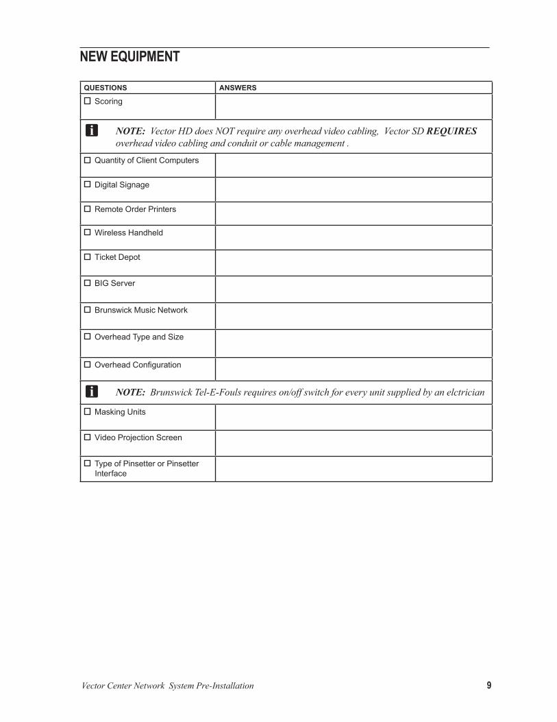
New equipmeNt
Questions Answers
Scoring
NOTE: VectorHDdoesNOTrequireanyoverheadvideocabling,VectorSDREQUIRES overheadvideocablingandconduitorcablemanagement.
Quantity of Client Computers
Digital Signage
Remote Order Printers
Wireless Handheld
Ticket Depot
BIG Server
Brunswick Music Network
Overhead Type and Size
OverheadConfiguration
NOTE: BrunswickTel-E-Foulsrequireson/offswitchforeveryunitsuppliedbyanelctrician
Masking Units
Video Projection Screen
Type of Pinsetter or Pinsetter Interface

10 Vector Center Network System Pre-Installation
diStaNCeS
Ceiling Height and Type of Ceiling NOTE:Openceilingsrequireconduitorcablemanagementsystem.
Questions Answers
Over the Approaches
NOTE: VectorHDDOESNOTrequireoverheadvideocabling,VectorSDDOESrequireoverheadvideocablingandconduitorcablemanagement.
Over Lanes
At the Masking Units
Over the Pinsetter
ethernet Questions Answers
Quantity of Switches on Curtain wall
Distance from Curtain Wall Switch to Control Desk Switch
Distance from Switch Overhead Structure to Control Desk Switch
NOTE: VectorSDDOESNOThavethisswitch.VectorHDDOEShavethisswitch.
Distance from Control Desk Switch toOffice
NOTE: Controldeskswitchisan8-portswitchincludinghomerunethernetcable.
Distance from Control Desk Switch to Client #1
Distance from Control Desk Switch to Client #2
Distance from Control Desk Switch to Client #3
Distance from Control Desk Switch to Client #4
Distance from Control Desk Switch to Client #5
Distance from Control Desk Switch to Client #6
intercomQuestions Answers
Distance from the closest end lane bowlers keypad or touch screen to the A/V box at control desk

Vector Center Network System Pre-Installation 11
audio/Video NOTE:TheVideoDistributionCentercanacceptavarietyofsignalsourcessuchassatellite
boxes,cableset-topboxes,orDVD/Blu-rayplayers.Theaudioandvideofromeachsourceisconnectedtoamodulatorthat“assigns”aunique“TV”channeltothesource.Thenumberofmodulatorspresentinthesystemisdeterminedbythenumberofvideosourcestothatwillbeavailablefordisplayonthemonitors.Whenchoosingmodulators,itisimportanttoconsidertheconnectiontypeavailableonthesignalsource,theoutputqualityofthemodulator(StandardorHighDefinition).
Three different modulators are available.
ModulAtor AvAilAble video input connections
AvAilAble Audio input connections
output resolution
480 (STANDARD DEFINITION)
COMPOSITE VIDEO ANALOG AUDIO (MONO) RCA
480I
720*(ENHANCED DEFINITION)
COMPONENT VIDEO DIGITAL AUDIO (STEREO)(RCA OR OPTICAL)
UP TO 720P
1080* (HIGH DEFINITION)
COMPONENT VIDEOVGA (15 PIN)
ANALOG AUDIO (STEREO)DIGITAL AUDIO
(RCA OR OPTICAL)
UP TO 1080I
*ConsideredHighDefinition
NOTE: ForanyvideosourcewithonlyanHDMIconnector,HDMItoComponentadapter,pn57-863630-000,mustbepurchased.VGAtoComponentadapter,pn57-863631-000isavailableforthethe720MODULATOR.Note:57-863633-000,VGAtoComponentadapterONLYFORTHE1080RESOLUTIONMODULATOR.
Questions Answers
Quantity of separate sources to display on overheads
NOTE: ProjectorsvideoisnotpartofVectorscoringandmustbesuppliedbycustomer.
Quantity of 480 resolution modulator
Quantity of 720 resolution modulator
Quantity of 1080 resolution modulator
Distance from the Video Distribution Center to the middle of the bowling lanes at the overheads
Will the audio be connected to an external audio system?
NOTE: Thismaycauseatimingissuebetweentheaudioandthevideosignalscustomerisresponsibleforsupplyingequipmenttocorrectissue.

12 Vector Center Network System Pre-Installation
Vector Scoring Installation Schedule IMPORTANT: The following is based on a typical 24 lane center. Schedules may vary
depending on center configuration and product to be installed.
CuStomer reSpoNSiBility NOTE: Allpreworkmustbecompletedpriortoequipmentarrival.ThisincludesControlDesk
assemblyandinstallation.
1. Site Survey to be performed by a Brunswick Field Engineer. The Field Engineer will need to meet with the center manager/proprietor, mechanic, electrician, and architect to cover the following:
a. Determine non-bowling hours. b. Provide a copy of league schedules. c. Review electrical system needs. d. Review overhead structure needs. e. Review control desk and back office configurations. f. Review Pre-Installation manual.
2. Prepare bowlers area for consoles: a. Trenching for using electrical conduit. b. Dual console risers for existing scorer replacement or surface molding. c. Any tile work or carpeting.
3. Prepare control desk and office areas for routing of interconnecting cables.
4. Electrician installs electrical system, subpanels, outlets, surge suppressors, and switches for Tel-E-Foul units..
5. Install overhead monitor support structure.
6. Center mechanic attends Scorer Maintenance school.
7. Center to have a storage area ready for arrival of new equipment.
8. Brunswick receives credit approval.
IMPORTANT: An installation will not be scheduled until credit is approved and structural certificates are received.
9. Brunswick receives structural certification from bowling center.
Vector Center Network System Pre-Installation 13
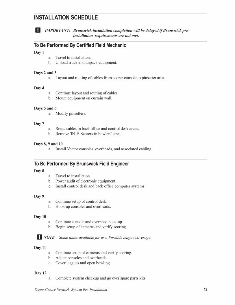
iNStallatioN SChedule
IMPORTANT: Brunswick installation completion will be delayed if Brunswick pre-installation requirements are not met.
To Be Performed By Certified Field MechanicDay 1 a. Travel to installation. b. Unload truck and unpack equipment.
Days 2 and 3 a. Layout and routing of cables from scorer console to pinsetter area.
Day 4 a. Continue layout and routing of cables. b. Mount equipment on curtain wall.
Days 5 and 6 a. Modify pinsetters. Day 7 a. Route cables in back office and control desk areas. b. Remove Tel-E-Scorers in bowlers’ area.
Days 8, 9 and 10 a. Install Vector consoles, overheads, and associated cabling.
To Be Performed By Brunswick Field EngineerDay 8 a. Travel to installation. b. Power audit of electronic equipment. c. Install control desk and back office computer systems. Day 9 a. Continue setup of control desk. b. Hook-up consoles and overheads.
Day 10 a. Continue console and overhead hook-up. b. Begin setup of cameras and verify scoring.
NOTE: Somelanesavailableforuse.Possibleleaguecoverage.
Day 11 a. Continue setup of cameras and verify scoring. b. Adjust consoles and overheads. c. Cover leagues and open bowling.
Day 12 a. Complete system checkup and go over spare parts kits.

14 Vector Center Network System Pre-Installation
To Be Performed By Brunswick Field TrainerDay 9 a. Travel to installation. b. Control desk management training.
Day 10 a. Scorer training. b. Control desk session. c. Possible league coverage.
Day 11 a. Continue control desk session. b. Cover leagues and open bowling.
Days 12 and 13 a. Back office session (League Record Service, Tournament, Open Bowler Data Base, etc.) b. Cover leagues and open bowling.

Vector Center Network System Pre-Installation 15
ImportantThis document contains information on electrical, installation, conduit, and lighting for Brunswick automatic scorers. It also contains the information necessary for the preparation of a site conforming to Brunswick specifications. Any deviation from these specifications could cause problems to your equipment that may be difficult to detect and/or correct. If you have questions regarding this document, call Brunswick Technical Support at 1-800-323-8141 (option 1).
When planning to install Brunswick electronic scoring equipment, the customer is required to provide an isolated ground (I.G.) electrical subpanel which is solely dedicated to those electronic systems with an isolated neutral and ground buss. These requirements are necessary to prevent electrical noise and damage from lightning strikes. An improperly grounded system can also result in memory losses, erroneous signals, and/or component failures. The isolated ground subpanel must be installed by a licensed electrician and must meet all local and national codes.
Surge SuppreSSioNA transient voltage surge suppressor (TVSS) is supplied with the scoring system. The installation of this device is the responsibility of the customer through a licensed electrician. The unit will be installed on the “Pinsetter” and “Scoring” subpanels.. This unit is designed for the most demanding environment and incorporates multistage filtration in its design. The sine wave tracking series is engineered to remove the more complex disturbances found in the electrical environment, in particular, high and low voltage ringing transients and harmonic activity.
NOTE: Thesurgesuppressorwiresshouldbeasshortaspossible,withnocoilingwheninstalledontheI.G.subpanel.TheTVSSdeviceisprovidedwithaplasticcouplertoinsulatetheunitfromthesubpanel.
BruNSwiCk’S reSpoNSiBilityBrunswick scorer consoles are shipped with the necessary hardware for wood and cement floor installations. The aircraft cable for suspending the overhead monitors will be supplied by Brunswick.
power CoNditioNiNgIn some areas, additional power conditioning or uninterrupted power supply (UPS) equipment may be required to insure optimum performance of your scoring equipment. The purchase and installation of any power conditioning equipment is the responsibility of the customer, including a UPS system. If the bowling center is located in an area that has a history of frequent power failures or interruptions, the customer is advised to contact the Brunswick Electronic Repair. The Brunswick Electronic Repair Department will assist the customer with any additional equipment specifications or Brunswick approved power conditioning equipment required.
warNiNgThis equipment generates, uses, and can radiate radio frequency energy and if not installed and used in accordance with the pre-installation manual, may cause interference to radio communications. It has been tested and found to comply with the limits for a Class A computing device pursuant to Subpart J of Part 15 of F.C.C. Rules, which are designed to provide reasonable protection against such interference when operated in a commercial environment. Operation of this equipment in a residential area is likely to cause interference in which case the user, at his own expense, will be required to take whatever measures may be required to correct the interference.

16 Vector Center Network System Pre-Installation
iSolated grouNd reCeptaCleS - NeC 250-74 exCeptioN 4Where required, for the reduction of electrical noise (electromagnetic interference) on the grounding circuit, a receptacle in which the grounding terminal is purposely insulated from the receptacle mounting means shall be permitted. The receptacle grounding terminal shall be grounded by an insulated equipment grounding conductor run with the circuit conductors to the electronic subpanel.
grouNdiNg CoNduCtor - NeC 384-27The grounding conductor shall be permitted to pass through one or more subpanels without connection to the panel board grounding terminal as permitted by Section 384-27 Exception, so as to terminate directly at the applicable derived system or service grounding terminal.
exteNded power outageThe circuit breakers (electronic subpanel) must be clearly identified and should be left on at all times under normal operation. If power is to be out for an extended period of time, it is recommended that circuit breakers to the electronic equipment be turned off. When power is restored, transient voltages could be induced into the equipment if circuit breakers are not off.
CarpetiNg iN BowlerS’ areaIt is not recommended mounting consoles on carpeting. Carpeting may cause static which can be induced into electronic equipment. If carpeting is necessary in the bowlers’ area, it is recommended that anti-static type of carpeting be used.
CarpetiNg iN eleCtroNiCS areaSIt’s the Customer’s Responsibility: If carpeting is to be installed at the site, it must be a computer-grade type which will generate no more than 2,000 to 3,000 volts of static discharge at 20% relative humidity and a temperature of 22°C (72°F). If carpeting is already installed and is not of a computer-grade type, it should be treated with an antistatic or anti-shock solution after it is cleaned. The frequency of these treatments depends on the amount of floor traffic in the room. Raising the humidity level should also be considered to control the generation of static electricity. Maintain a humidity level of 40-60% to control the generation of static electricity.
atmoSpheriC CoNditioNSIt is important that the climate control is maintained throughout the center. Indoor humidity is a large factor in lane conditions as well preventing static electricity. A relative level of 40% must be maintained to obtain optimum characteristics and performance from all equipment. A minimum of 35% and a maximum of 50% is possible if the temperature is controlled and constant.

Vector Center Network System Pre-Installation 17
Electrical OvervieweleCtriCal SuBpaNel SpeCifiCatioNS
IMPORTANT!: All subpanels and wiring MUST comply with local and national electrical codes.
Pinsetter Subpanel – The Pinsetter subpanel used to power the GS-Series pinsetters and other Brunswick equipment must be powered directly from the primary main service subpanel or transformer and must be three phase. Non-Brunswick equipment including electronic video games, arc welders, HVAC, compressors, etc., cannot share this sub-panel.
Scoring Subpanel (Isolated Ground) – The scoring subpanel must be powered from the main service subpanel or trnsformer. This is an isolated ground subpanel that is REQUIRED for all of Brunswick electronic equipment and installed according to National Electric Code 250-74 or similar isolated ground guidelines according to local code and national electric codes. All the outlets for this panel must be an isolated receptacle similar to “Hubbell IG 5262” receptacles.
The ONLY type of equipment to be installed in the subpanels:
Pinsetter Subpanel
• GS-X Pinsetter
• Ball Lift
• Tel-E-Foul
• Lane Machine
• Ball Polisher
• Lightworx
• Lanescape Video Masking Unit
• Ticket Depot
Scoring Subpanel (Isolated Ground) • Scoring Computer
• 32”/40”/46”/55” Overhead Monitors
• Display Controller
• HD Video Distribution Center
• Server Computer
• Client Computer
• Automated - Pinball Wizard • Digital Signage
• BIG Server
WARNING! Any Non-Brunswick equipment circuits located in these subpanels will VOID ALL WARRANTY. This includes electronic video games, arc welders, HVAC, compressors, etc.

18 Vector Center Network System Pre-Installation
IMPORTANT!: Split house centers with multiple subpanels require a single source of power and ground from main service.

Vector Center Network System Pre-Installation 19
SCoriNg (iSolated grouNd) SuBpaNel aNd Surge SuppreSSor iNStallatioN

20 Vector Center Network System Pre-Installation
eleCtriCal quiCk refereNCe CheCkliSt
WARNING!: FAILURE to COMPLY with the Electrical Quick Reference and Pre-Installation Manual specification will VOID ALL WARRANTIES. All electrical work must be completed before the engineer arrives on-site.
A SEPARATE and DEDICATED subpanel must be provided and DIRECTLY wired to main service, hereby called the “SCORING SUBPANEL.” If a transformer is installed, the primary of the transformer to main service must have a separate ground wire.
Split house bowling centers with multiple subpanels REQUIRE a single source of power from main service entrance.
The ISOLATED GROUND and NEUTRAL buss bars CANNOT be BONDED to the “Scoring” subpanel. Reference NEC 250-74 Exception 4.
EARTH GROUND conductor MUST BE a minimum of #6 AWG wire or larger.
The electrician MUST perform a CONTINUITY check on the electronics subpanel to ensure NO conduit to ISOLATED GROUND and/or NEUTRAL shorts exist.
Greenfield or conduit CANNOT be used as the EQUIPMENT GROUND conductor for the system.
Each ISOLATED GROUND circuit has a SEPARATE hot, neutral, and ground wire. Example: 10 circuits = 10 hots, 10 neutrals, 10 grounds.
Nonautomatic scorer equipment CANNOT share our Scoring subpanel or conduit raceways.
All branch circuit runs OVER 200 FEET from all subpanels must be #10 AWG wire or larger.
Class-A CERTIFIED ground is recommended and should be measured at main service.
Floating receptacles in the consoles MUST BE insulated. Metallic electrical boxes CANNOT touch console metal base. If local code permits, you may install “SO” cords with insulated female cord cap receptacle.
NOTE:Itisveryimportanttoreadalltheinformationavailablefortheequipmentbeinginstalledinyourbowlingcenter.Anydeviationfromthesespecificationscouldpotentiallycauseproblemstoyourelectronicautomaticscoringequipmentthatmaybedifficulttodetectand/orcorrect.

Vector Center Network System Pre-Installation 21
SeleCtiNg a Surge SuppreSSor
A flow chart diagram is shown below to assist you in identifying if the Scoring subpanel is SINGLE phase or THREE phase and which surge suppressor is needed.
SurgeSuppressor
NeededModel Voltage/Phase Wye/
Delta No. of Wires Brunswick Part No.
1 TK-TT160-3Y208-FB 120/208/Three Wye 4 Wire + Ground 57-861915-0002 TK-TT160-1S240-FB 120/240/Single Wye 3 Wire + Ground 57-861917-0003 TK-TT160-3D240-FB 120/240/Three Delta 4 Wire + Ground 57-861916-0004 TK-TT160-NN240-FB 240NN/Three Delta 3 Wire + Ground 57-861918-0005 TK-TT160-3Y380-FB 220/380/Three Wye 4 Wire + Ground 57-861919-000

22 Vector Center Network System Pre-Installation
CoNduit aNd low Voltage CaBle SpeCifiCatioNS It is the customer’s responsibility to provide a raceway or means to run wires from the equipment, located at the Control Desk:
• To the Approach Area • To the Office • From the network switch on the curtain eall to the network switch on the control desk. • Overhead Monitors
Additional low voltage cables are routed from the office to the closest end lane pair pinsetter area. Various ways of doing this can be discussed with the Brunswick Service Representative at the time of the survey.
The interconnecting cables are supplied and installed by Brunswick and routed through suitable conduit.
When routing the conduit or interconnecting cables from the scoring computer to the control desk or office, extra care must be exercised to not place them near a noisy electrical environment.
IMPORTANT!: The cables need to be installed in conduit only when local codes require it.
1. Keep the conduit routing to a minimum, but keep in mind that routing them away from a noisy electrical environment is most important.
2. If conduit is required, only telephone or communication cables may be routed in the same conduit. Do not route them in conduit with any electrical equipment with high voltage power cables.
3. Do not lay the interconnecting cables or conduit raceways on top of, or close to fluorescent light fixtures. Route them as far from the fixtures as possible.
4. Keep cables as far away as possible from motors, compressors, and high voltage power cables. Do not lay them next to or closely parallel to existing high voltage electrical cables. When there is any doubt, contact your local representative, or contact the Brunswick Technical Support at 1-800-323-8141 (option 1), in the USA or Canada, or at 231-725-3300 for International. Fax number is 1-231-725-4667.
NOTE: Donotuseplumbing/waterpipeforlowvoltagecableconduits.Electrical Conduit must beusedforallconduit.Extrachargeswillbeappliedifplumbing/waterpipeissupplied.

Vector Center Network System Pre-Installation 23
eleCtriCal reCeptaCle loCatioNS
Bowler’s Keypads

24 Vector Center Network System Pre-Installation
Bowler’s Touchscreens

Vector Center Network System Pre-Installation 25
Isolated Ground
26 Vector Center Network System Pre-Installation
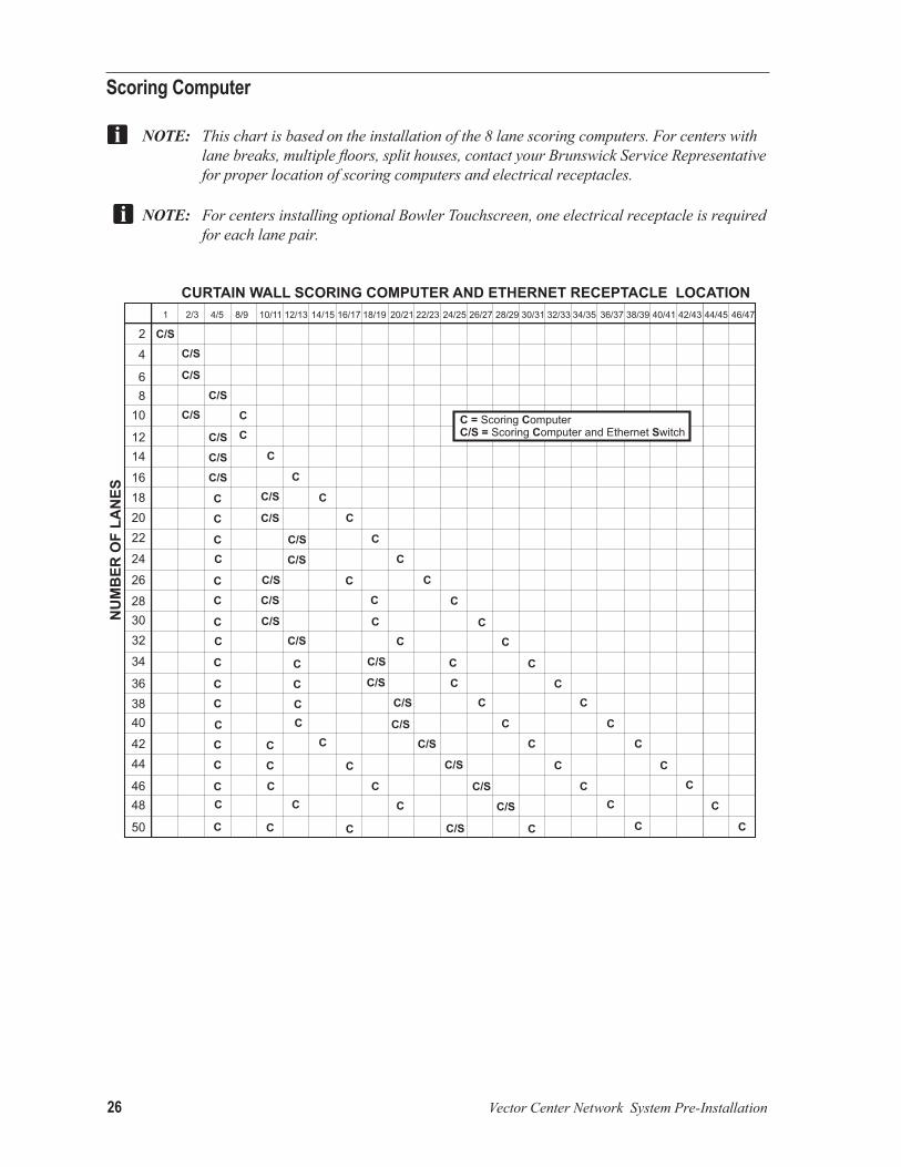
Scoring Computer
NOTE: Thischartisbasedontheinstallationofthe8lanescoringcomputers.Forcenterswithlanebreaks,multiplefloors,splithouses,contactyourBrunswickServiceRepresentativeforproperlocationofscoringcomputersandelectricalreceptacles.
NOTE:ForcentersinstallingoptionalBowlerTouchscreen,oneelectricalreceptacleisrequiredforeachlanepair.

Vector Center Network System Pre-Installation 27
CoNduit loCatioN iN floorThe illustration below shows a typical conduit network to accommodate all cables in the system. The conduit sizes shown apply to all scoring systems.
NOTE: AllconduitforlowvoltagecablesmustbeELECTRICAL CONDUIT NOT plumbing/waterconduit.

28 Vector Center Network System Pre-Installation
wood floor
instAllAtion inforMAtion
custoMer’s responsibility: BUILD RACEWAyS USING 2 x 4 LUMBER ON THE ExISTING FLOOR. COVER WITH TWO LAyERS OF 3/4” PLyWOOD, ONE LAyER OF MASONITE AND ONE LAyER OF TILE. IT IS NECESSARy TO CUT OUT A PORTION OF THE APPROACH HEADER TO ALLOW THE CABLES TO BE ROUTED UNDER THE APPROACH. REFER TO DIMENSIONS ABOVE FOR PLACEMENT OF 2 x 4 LUMBER.
THE REMAINING 2 x 4S MAy BE POSITIONED IN ANy MANNER THAT PROPERLy SUPPORTS THE FLOOR. ONE SUGGESTION IS TO PUT THE LUMBER ON 16” (406 MM) CENTERS.
Vector Center Network System Pre-Installation 29
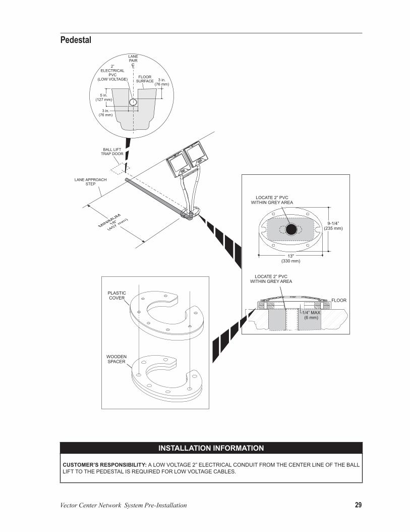
pedestal
instAllAtion inforMAtion
custoMer’s responsibility: A LOW VOLTAGE 2” ELECTRICAL CONDUIT FROM THE CENTER LINE OF THE BALL LIFT TO THE PEDESTAL IS REQUIRED FOR LOW VOLTAGE CABLES.

30 Vector Center Network System Pre-Installation
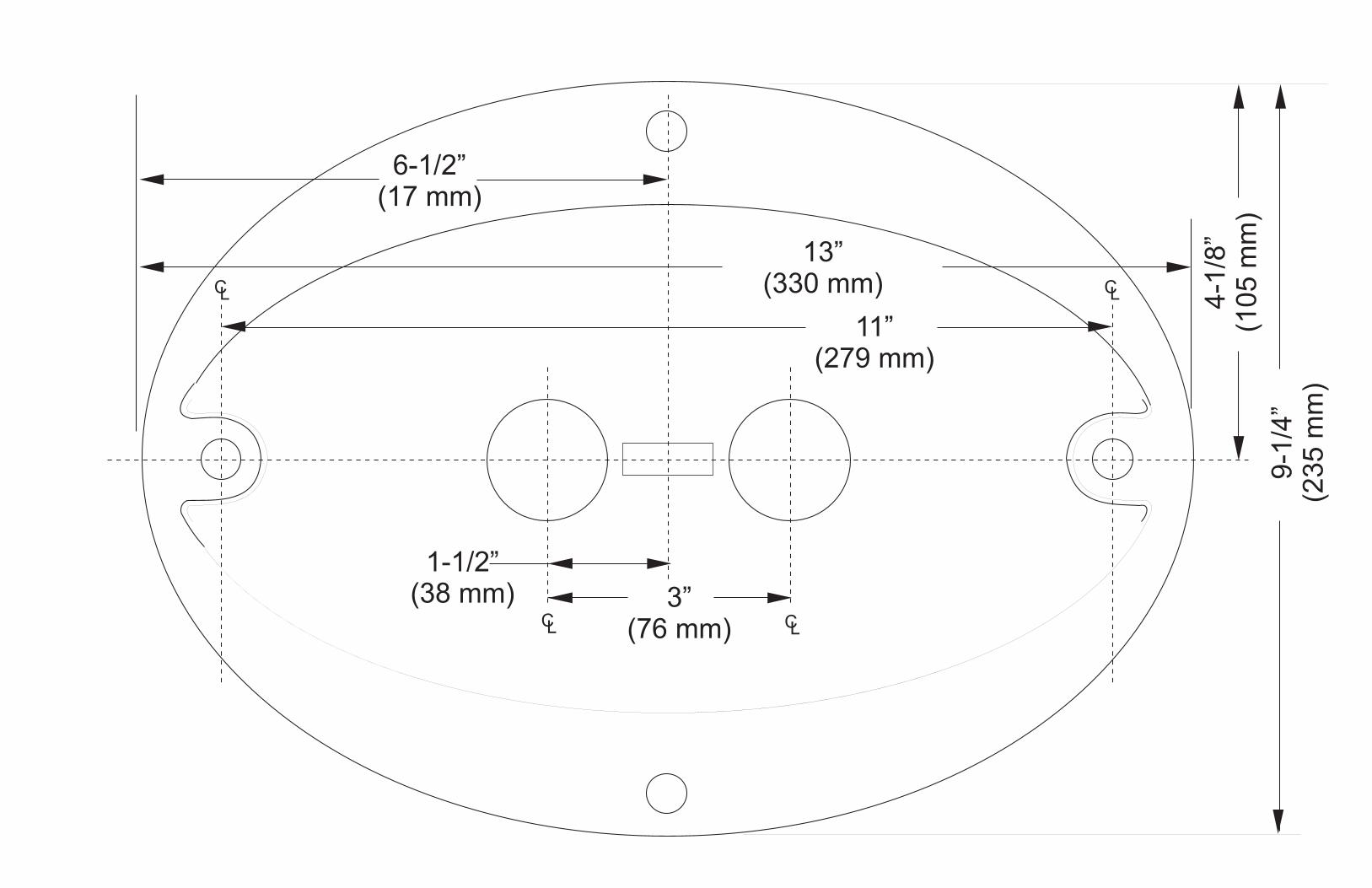
oval table
instAllAtion inforMAtion
custoMer’s responsibility: TRENCH OR ROUTE 2 EACH 2” ELECTRICAL CONDUIT FOR LOW VOLTAGE CABLES. THESE CONDUITS MUST BE 3” (76 MM) BELOW FLOOR SURFACE AND MEET LOCAL CODES.
NOTE:Aminimumspaceof25”(635mm)isrequiredbetweenthelaneapproachstepandscorer.
BRUNSWICk RESPONSIBILITy: SUPPLy AND ROUTE LOW VOLTAGE CABLES TO THE BOWLER’S kEyPAD OR TOUCH SCREEN.

Vector Center Network System Pre-Installation 31
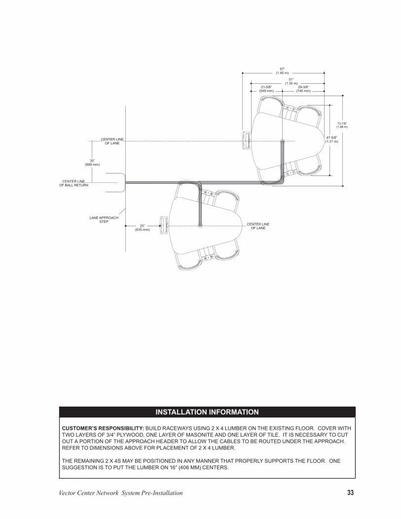
instAllAtion inforMAtion
custoMer’s responsibility: BUILD RACEWAyS USING 2 x 4 LUMBER ON THE ExISTING FLOOR. COVER WITH TWO LAyERS OF 3/4” PLyWOOD, ONE LAyER OF MASONITE AND ONE LAyER OF TILE. IT IS NECESSARy TO CUT OUT A PORTION OF THE APPROACH HEADER TO ALLOW THE CABLES TO BE ROUTED UNDER THE APPROACH. REFER TO DIMENSIONS ABOVE FOR PLACEMENT OF 2 x 4 LUMBER.
THE REMAINING 2 x 4S MAy BE POSITIONED IN ANy MANNER THAT PROPERLy SUPPORTS THE FLOOR. ONE SUGGESTION IS TO PUT THE LUMBER ON 16” (406 MM) CENTERS.

32 Vector Center Network System Pre-Installation
Triangle Table
instAllAtion inforMAtion
custoMer’s responsibility: TRENCH OR ROUTE 2 EACH 2” ELECTRICAL CONDUIT FOR LOW VOLTAGE CABLES. THESE CONDUITS MUST BE 3” (76 MM) BELOW FLOOR SURFACE AND MEET LOCAL CODES.
NOTE:Aminimumspaceof25”(635mm)isrequiredbetweenthelaneapproachstepandscorer.
brunswick responsibility: SUPPLy AND ROUTE LOW VOLTAGE CABLES TO THE BOWLER’S kEyPAD OR TOUCH SCREEN.
Vector Center Network System Pre-Installation 33
instAllAtion inforMAtion
custoMer’s responsibility: BUILD RACEWAyS USING 2 x 4 LUMBER ON THE ExISTING FLOOR. COVER WITH TWO LAyERS OF 3/4” PLyWOOD, ONE LAyER OF MASONITE AND ONE LAyER OF TILE. IT IS NECESSARy TO CUT OUT A PORTION OF THE APPROACH HEADER TO ALLOW THE CABLES TO BE ROUTED UNDER THE APPROACH. REFER TO DIMENSIONS ABOVE FOR PLACEMENT OF 2 x 4 LUMBER.
THE REMAINING 2 x 4S MAy BE POSITIONED IN ANy MANNER THAT PROPERLy SUPPORTS THE FLOOR. ONE SUGGESTION IS TO PUT THE LUMBER ON 16” (406 MM) CENTERS.
34 Vector Center Network System Pre-Installation
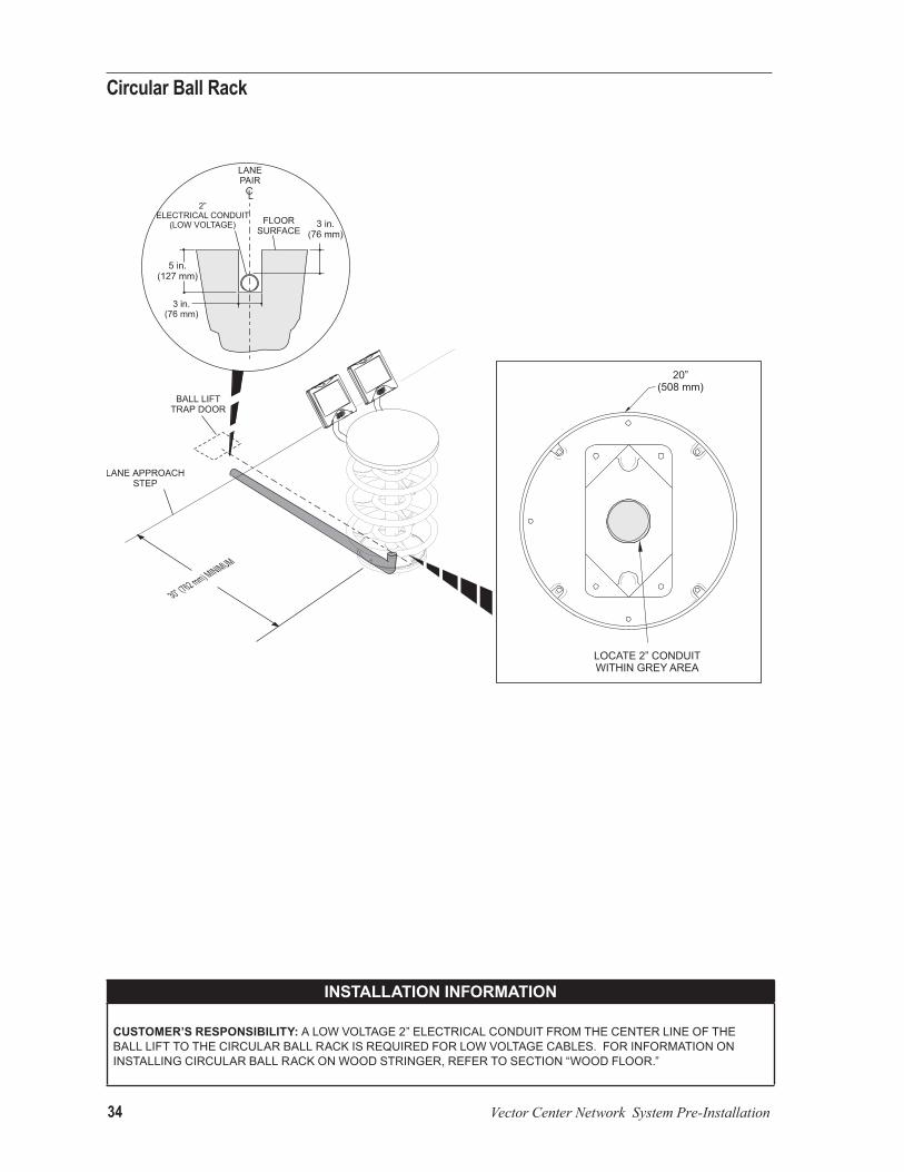
Circular Ball Rack
instAllAtion inforMAtion
custoMer’s responsibility: A LOW VOLTAGE 2” ELECTRICAL CONDUIT FROM THE CENTER LINE OF THE BALL LIFT TO THE CIRCULAR BALL RACk IS REQUIRED FOR LOW VOLTAGE CABLES. FOR INFORMATION ON INSTALLING CIRCULAR BALL RACk ON WOOD STRINGER, REFER TO SECTION “WOOD FLOOR.”
Vector Center Network System Pre-Installation 35
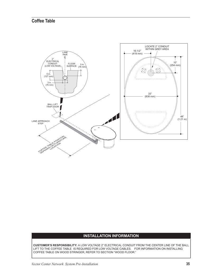
Coffee Table
instAllAtion inforMAtion
custoMer’s responsibility: A LOW VOLTAGE 2” ELECTRICAL CONDUIT FROM THE CENTER LINE OF THE BALL LIFT TO THE COFFEE TABLE IS REQUIRED FOR LOW VOLTAGE CABLES. FOR INFORMATION ON INSTALLING COFFEE TABLE ON WOOD STRINGER, REFER TO SECTION “WOOD FLOOR.”
36 Vector Center Network System Pre-Installation
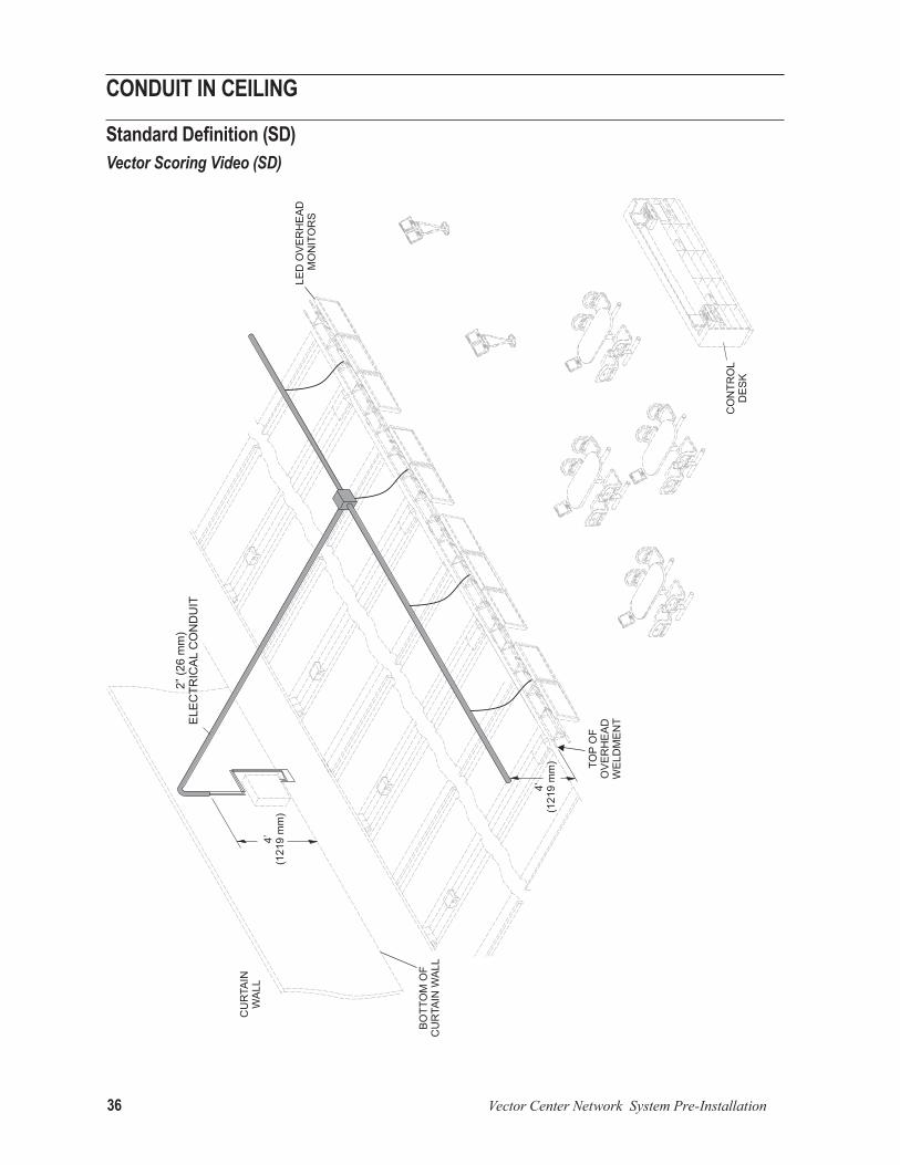
CoNduit iN CeiliNg
Standard Definition (SD) Vector Scoring Video (SD)
Vector Center Network System Pre-Installation 37
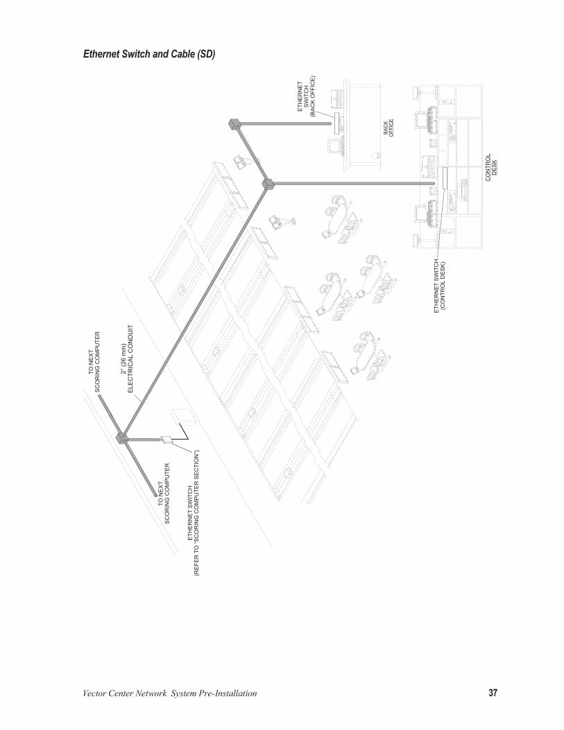
Ethernet Switch and Cable (SD)

38 Vector Center Network System Pre-Installation
High Definition (HD) Video
Ethernet Switch and Cable Location (HD)

Vector Center Network System Pre-Installation 39
Electronic Equipment SpecificationsSCoriNg Computer
Direct Connect GS-98, GS-X and Non-GS PinsettersElectrical Information
volts Hertz Ac/dc pHAse AMpsper unit wAtts brAncH
circuit cusoMer responsibility
100-130 50/60 AC 1 2.5 300 2 WIRES + GROUND
INSTALL CIRCUIT WITH RECEPTACLE OR EQUIVALENT. NO MORE THAN 6 LANE
PAIRS PER 20 AMP CIRCUIT.
200-220 50/60 AC 1 1.25 300 2 WIRES + GROUND
INSTALL CIRCUIT WITH RECEPTACLE. NO MORE THAN 10 LANE PAIRS PER 16
AMP CIRCUIT.
instAllAtion inforMAtion
custoMer’s responsibility: PROVIDE A SUITABLE LOCATION ON THE CURTAIN WALL AS SHOWN ABOVE FOR THE VECTOR SCORING COMPUTER. INSTALL RECEPTACLE ON THE CURTAIN WALL. REFER TO LOCATION CHART FOR ExACT LOCATION.
IF A CURTAIN WALL IS NOT AVAILABLE, A SUPPORT STRUCTURE MUST BE INSTALLED TO HANDLE THE 100 LB. STATIC WEIGHT LOAD PER LANE PAIR.
NOTE:IfBrunswickmaskingunitsarepresent,themountingpanelmaybemountedtothemaskingunitstructurewithoptionalbracketkit.
brunswick responsibility: TO INSTALL THE ELECTRONICS MOUNTING PLATE ON THE CURTAIN WALL OR SUITABLE STRUCTURE.

40 Vector Center Network System Pre-Installation
GS-10, GS-92, GS-96 and Non-Direct GS-98 Pinsetters Electrical Information
volts Hertz Ac/dc pHAse AMpsper unit wAtts brAncH
circuit cusoMer responsibility
100-130 50/60 AC 1 3.5 420 2 WIRES + GROUND
INSTALL CIRCUIT WITH QUAD RECEPTACLE. NO MORE THAN 4 LANES
PAIRS PER 20 AMP CIRCUIT.
200-240 50/60 AC 1 1.75 420 2 WIRES + GROUND
INSTALL CIRCUIT WITH QUAD RECEPTACLE. NO MORE THAN 7 LANES
PAIRS PER 16 AMP CIRCUIT.
instAllAtion inforMAtion
custoMer’s responsibility: PROVIDE A SUITABLE LOCATION ON THE CURTAIN WALL AS SHOWN ABOVE FOR THE VECTOR SCORING COMPUTER. INSTALL AN QUAD RECEPTACLE OR EQUIVALENT ON THE CURTAIN WALL. REFER TO LOCATION CHART FOR ExACT LOCATION.
IF A CURTAIN WALL IS NOT AVAILABLE, A SUPPORT STRUCTURE MUST BE INSTALLED TO HANDLE THE 100 LB. STATIC WEIGHT LOAD PER LANE PAIR.
NOTE:IfBrunswickmaskingunitsarepresent,themountingpanelmaybemountedtothemaskingunitstructurewithoptionalbracketkit.
brunswick responsibility: TO INSTALL THE ELECTRONICS MOUNTING PLATE ON THE CURTAIN WALL OR SUITABLE STRUCTURE.

Vector Center Network System Pre-Installation 41
Bowler’S touChSCreeN power SupplyElectrical Information
volts Hertz Ac/dc pHAse AMpsper unit wAtts brAncH
circuit cusoMer responsibility
100-130 50/60 AC 1 .5 60 2 WIRES + GROUND
INSTALL CIRCUIT WITH RECEPTACLE. NO MORE THAN 24 LANES PAIRS PER 20
AMP CIRCUIT.
200-240 50/60 AC 1 .25 60 2 WIRES + GROUND
INSTALL CIRCUIT WITH RECEPTACLE. NO MORE THAN 20 LANES PAIRS PER 16
AMP CIRCUIT.
instAllAtion inforMAtion
custoMer’s responsibility: PROVIDE A SUITABLE LOCATION ON THE CURTAIN WALL AS SHOWN ABOVE FOR THE BOWLER’S TOUCHSCREEN POWER SUPPLy. INSTALL A RECEPTACLE ON THE CURTAIN WALL. REFER TO LOCATION CHART FOR ExACT LOCATION.
NOTE:Atlocationswherethereisascoringcomputerpresent,bowler’sTouchscreenwillsharethereceptaclewiththescoringcomputer.
brunswick responsibility: TO INSTALL THE BOWLER’S TOUCHSCREEN ON THE CURTAIN WALL OR SUITABLE STRUCTURE.

42 Vector Center Network System Pre-Installation
automated Bumper SyStem - piNBall wizard
Electrical Information
volts Hertz Ac/dc pHAse AMpsper unit wAtts brAncH
circuit cusoMer responsibility
100-130 50/60 AC 1 3.0 360
2 WIRES + ISOLATED GROUND #12 AWG
WIRE
INSTALL CIRCUIT WITH 120 VOLT HUBBELL I.G. 5262 RECEPTACLE OR
EQUIVALENT. NO MORE THAN 4 LANES PAIRS PER 20 AMP CIRCUIT.
200-240 50/60 AC 1 1.5 360
2 WIRES + ISOLATED GROUND #12AWG
WIRE
INSTALL CIRCUIT WITH APPROPRIATE I.G. RECEPTACLE. NO MORE THAN 4 LANES PAIRS PER 16 AMP CIRCUIT.
instAllAtion inforMAtion
custoMer’s responsibility: THE CUSTOMER MUST PROVIDE ELECTRICAL POWER SOURCE THAT COMPLIES WITH LOCAL CODE.
IMPORTANT: This power source should be supplied from scorer I.G. sub-panel.
Vector Center Network System Pre-Installation 43
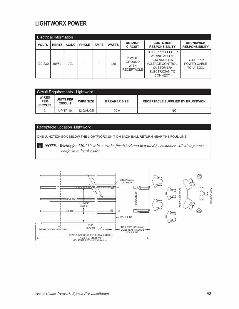
lightworx power
Electrical Information
volts Hertz Ac/dc pHAse AMps wAtts brAncH circuit
custoMer responsibility
brunswick responsibility
120-230 50/60 AC 1 1 120
2 WIRE GROUND
WITH RECEPTACLE
TO SUPPLy FEEDER WIRING AND “J” BOx AND LOW
VOLTAGE CONTROL. CUSTOMER/
ELECTRICIAN TO CONNECT.
TO SUPPLy POWER CABLE
TO “J” BOx.
Circuit Requirements - Lightworxwires
per circuit
units per circuit wire size breAker size receptAcle supplied by brunswick
3 UP TP 10 12 GAUGE 20 A NO
Receptacle Location Lightworx
ONE JUNCTION BOx BELOW THE LIGHTWORx UNIT ON EACH BALL RETURN NEAR THE FOUL LINE.
NOTE: Wiringfor120-230voltsmustbefurnishedandinstalledbycustomer.Allwiringmustconformtolocalcodes

44 Vector Center Network System Pre-Installation
tel-e-foul
Electrical Information
volts Hertz Ac/dc pHAse AMps wAtts brAncH circuit
custoMer responsibility
brunswick responsibility
120 50/60 AC 1 1 120 3 WIRE INSULATED
GROUND WITH
RECEPTACLE
TO SUPPLy FEEDER WIRING AND “J” BOx AND
LOW VOLTAGE CONTROL.
CUSTOMER/ELECTRICIAN TO
CONNECT.
TO SUPPLy AND INSTALL TEL-E-FOUL AND
POWER CABLE TO “J” BOx.230 50/60 AC 1 .5 120
Circuit Requirements - Tel-E-Foulwires
per circuit
units per circuit wire size breAker size receptAcle supplied by brunswick
3 UP TP 10 12 GAUGE 20 A NO
Receptacle Location Tel-E-Foul
ONE JUNCTION BOx BELOW THE TEL-E-FOUL UNITS ON EACH BALL RETURN NEAR THE FOUL LINE
NOTE:Oneon/offswitchperTel-E-Foul.
NOTE: Wiringfor120-230voltsmustbefurnishedandinstalledbycustomer.Allwiringmustconformtolocalcodes
Vector Center Network System Pre-Installation 45
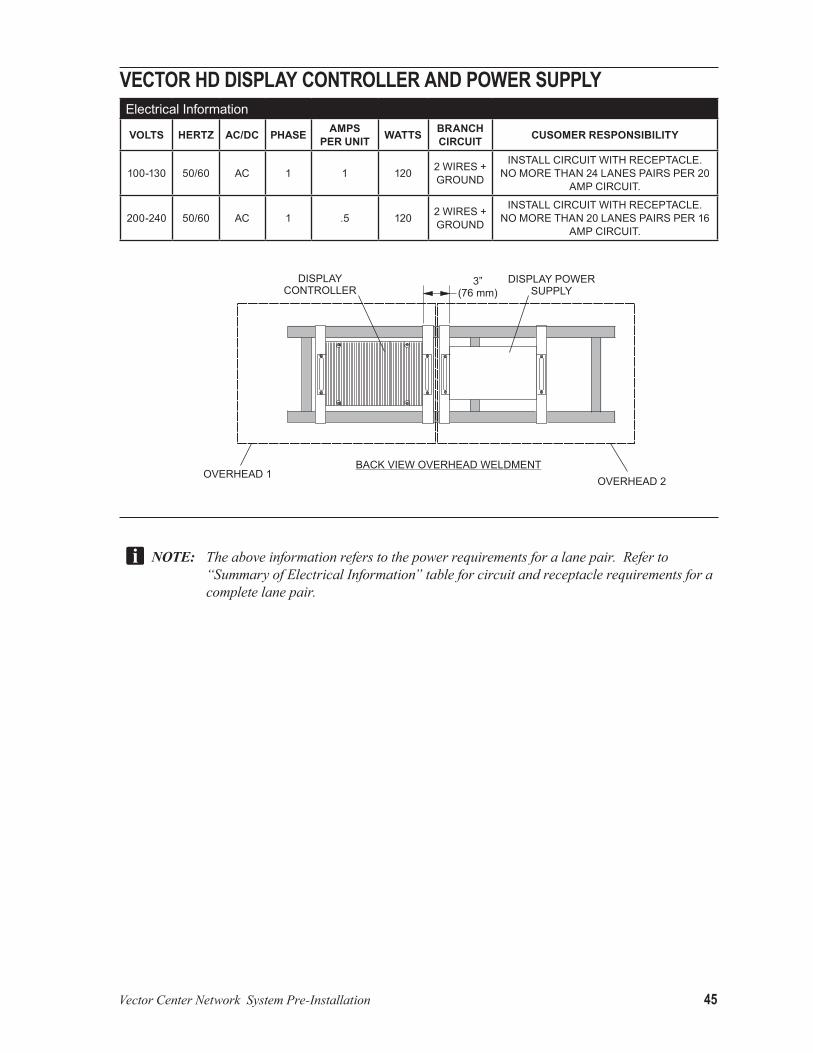
VeCtor hd diSplay CoNtroller aNd power SupplyElectrical Information
volts Hertz Ac/dc pHAse AMpsper unit wAtts brAncH
circuit cusoMer responsibility
100-130 50/60 AC 1 1 120 2 WIRES + GROUND
INSTALL CIRCUIT WITH RECEPTACLE. NO MORE THAN 24 LANES PAIRS PER 20
AMP CIRCUIT.
200-240 50/60 AC 1 .5 120 2 WIRES + GROUND
INSTALL CIRCUIT WITH RECEPTACLE. NO MORE THAN 20 LANES PAIRS PER 16
AMP CIRCUIT.
NOTE: Theaboveinformationreferstothepowerrequirementsforalanepair.Referto“SummaryofElectricalInformation”tableforcircuitandreceptaclerequirementsforacompletelanepair.

46 Vector Center Network System Pre-Installation
32” oVerhead led moNitorElectrical Information
eQuipMent volts Hertz Ac/dc pHAse AMpsper unit wAtts brAncH
circuitcusoMer
responsibility
32” OVERHEAD LED WITH SD INTERFACE
100-130 50/60 AC 1 1.2 942 WIRES + GROUND
INSTALL CIRCUIT WITH RECEPTACLE. 200-240 50/60 AC 1 .6 94
32” OVERHEAD LED WITH HD INTERFACE
100-130 50/60 AC 1 1.7 154 2 WIRES + GROUND
INSTALL CIRCUIT WITH RECEPTACLE. 200-240 50/60 AC 1 0.85 154
NOTE: Theaboveinformationreferstothepowerrequirementsforasingleunitlanepair.Referto“SummaryofElectricalInformation”tableforcircuitandreceptaclerequirementsforacompletelanepair.
instAllAtion inforMAtion
custoMer’s responsibility: USING THE PREFERRED METHOD OF SUPPORT, THE OVERHEAD IS TO BE SUSPENDED FROM PIPE SUPPORTS WHICH ARE SUPPORTED FROM ROOF TRUSSES. THE RECEPTACLE IS TO BE INSTALLED FLUSH WITH THE CEILING AND LOCATED NEAR THE REAR SUSPENSION WIRE ON THE CENTER LINE OF A PAIR OF LANES. THE CUSTOMER IS RESPONSIBLE FOR SUPPLyING, INSTALLING, AND MAINTAINING THE PROPER POSITION OF THE SUPPORT PIPE. THE CUSTOMER IS ALSO RESPONSIBLE FOR HAVING THE STRUCTURE CERTIFICATE FORM COMPLETED By AN ARCHITECT OR STRUCTURAL ENGINEER. SEE “WIDE SCREEN LED OVERHEAD VIDEO DISPLAy CERTIFICATE FOR SUPPORT WEIGHT SPECIFICATIONS. TRIPLE OVERHEADS REQUIRE A QUAD RECEPTACLE CENTERED TO THE REAR OF THE SUPPORT WIRE.
NOTE:Supportpipesmustbeasstraightaspossible.Anyvariationinthesupportwillaffectoverheadpositioning.

Vector Center Network System Pre-Installation 47
40” oVerhead led moNitorElectrical Information
eQuipMent volts Hertz Ac/dc pHAse AMpsper unit wAtts brAncH
circuitcusoMer
responsibility
40” OVERHEAD LEDWITH SD
INTERFACE
100-130 50/60 AC 1 1.2 1192 WIRES + GROUND
INSTALL CIRCUIT WITH RECEPTACLE. 200-240 50/60 AC 1 .6 119
40” OVERHEAD LED WITH HD
INTERFACE
100-130 50/60 AC 1 1.7 179 2 WIRES + GROUND
INSTALL CIRCUIT WITH RECEPTACLE. 200-240 50/60 AC 1 0.85 179
NOTE: Theaboveinformationreferstothepowerrequirementsforasingleunitlanepair.Referto“SummaryofElectricalInformation”tableforcircuitandreceptaclerequirementsforacompletelanepair.
instAllAtion inforMAtion
custoMer’s responsibility: USING THE PREFERRED METHOD OF SUPPORT, THE OVERHEAD IS TO BE SUSPENDED FROM PIPE SUPPORTS WHICH ARE SUPPORTED FROM ROOF TRUSSES. THE RECEPTACLE IS TO BE INSTALLED FLUSH WITH THE CEILING AND LOCATED NEAR THE REAR SUSPENSION WIRE ON THE CENTER LINE OF A PAIR OF LANES. THE CUSTOMER IS RESPONSIBLE FOR SUPPLyING, INSTALLING, AND MAINTAINING THE PROPER POSITION OF THE SUPPORT PIPE. THE CUSTOMER IS ALSO RESPONSIBLE FOR HAVING THE STRUCTURE CERTIFICATE FORM COMPLETED By AN ARCHITECT OR STRUCTURAL ENGINEER. SEE “WIDE SCREEN LED OVERHEAD VIDEO DISPLAy CERTIFICATE FOR SUPPORT WEIGHT SPECIFICATIONS. TRIPLE OVERHEADS REQUIRE A QUAD RECEPTACLE CENTERED TO THE REAR OF THE SUPPORT WIRE.
NOTE:Supportpipesmustbeasstraightaspossible.Anyvariationinthesupportwillaffectoverheadpositioning.

48 Vector Center Network System Pre-Installation
46” oVerhead led moNitorElectrical Information
eQuipMent volts Hertz Ac/dc pHAse AMpsper unit wAtts brAncH
circuitcusoMer
responsibility
46” OVERHEAD LEDWITH SD
INTERFACE
100-130 50/60 AC 1 1.2 1362 WIRES + GROUND
INSTALL CIRCUIT WITH RECEPTACLE.
200-240 50/60 AC 1 .6 136
46” OVERHEAD LED WITH HD
INTERFACE
100-130 50/60 AC 1 1.7 196 2 WIRES + GROUND
INSTALL CIRCUIT WITH RECEPTACLE. 200-240 50/60 AC 1 0.85 196
NOTE: Theaboveinformationreferstothepowerrequirementsforasingleunitlanepair.Referto“SummaryofElectricalInformation”tableforcircuitandreceptaclerequirementsforacompletelanepair.
instAllAtion inforMAtion
custoMer’s responsibility: USING THE PREFERRED METHOD OF SUPPORT, THE OVERHEAD IS TO BE SUSPENDED FROM PIPE SUPPORTS WHICH ARE SUPPORTED FROM ROOF TRUSSES. THE RECEPTACLE IS TO BE INSTALLED FLUSH WITH THE CEILING AND LOCATED NEAR THE REAR SUSPENSION WIRE ON THE CENTER LINE OF A PAIR OF LANES. THE CUSTOMER IS RESPONSIBLE FOR SUPPLyING, INSTALLING, AND MAINTAINING THE PROPER POSITION OF THE SUPPORT PIPE. THE CUSTOMER IS ALSO RESPONSIBLE FOR HAVING THE STRUCTURE CERTIFICATE FORM COMPLETED By AN ARCHITECT OR STRUCTURAL ENGINEER. SEE “WIDE SCREEN LED OVERHEAD VIDEO DISPLAy CERTIFICATE FOR SUPPORT WEIGHT SPECIFICATIONS. TRIPLE OVERHEADS REQUIRE A QUAD RECEPTACLE CENTERED TO THE REAR OF THE SUPPORT WIRE.
NOTE:Supportpipesmustbeasstraightaspossible.Anyvariationinthesupportwillaffectoverheadpositioning.

Vector Center Network System Pre-Installation 49
55” oVerhead led moNitorElectrical Information
eQuipMent volts Hertz Ac/dc pHAse AMpsper unit wAtts brAncH
circuitcusoMer
responsibility
55” OVERHEAD LED WITH SD INTERFACE
100-130 50/60 AC 1 1.9 1652 WIRES + GROUND
INSTALL CIRCUIT WITH RECEPTACLE.
200-240 50/60 AC 1 .95 165
55” OVERHEAD LED WITH HD
INTERFACE
100-130 50/60 AC 1 2.4 224 2 WIRES + GROUND200-240 50/60 AC 1 1.2 224
NOTE: Theaboveinformationreferstothepowerrequirementsforasingleunitlanepair.Referto“SummaryofElectricalInformation”tableforcircuitandreceptaclerequirementsforacompletelanepair.
instAllAtion inforMAtion
custoMer’s responsibility: USING THE PREFERRED METHOD OF SUPPORT, THE OVERHEAD IS TO BE SUSPENDED FROM PIPE SUPPORTS WHICH ARE SUPPORTED FROM ROOF TRUSSES. THE RECEPTACLE IS TO BE INSTALLED FLUSH WITH THE CEILING AND LOCATED NEAR THE REAR SUSPENSION WIRE ON THE CENTER LINE OF A PAIR OF LANES. THE CUSTOMER IS RESPONSIBLE FOR SUPPLyING, INSTALLING, AND MAINTAINING THE PROPER POSITION OF THE SUPPORT PIPE. THE CUSTOMER IS ALSO RESPONSIBLE FOR HAVING THE STRUCTURE CERTIFICATE FORM COMPLETED By AN ARCHITECT OR STRUCTURAL ENGINEER. SEE “WIDE SCREEN LED OVERHEAD VIDEO DISPLAy CERTIFICATE FOR SUPPORT WEIGHT SPECIFICATIONS. TRIPLE OVERHEADS REQUIRE A QUAD RECEPTACLE CENTERED TO THE REAR OF THE SUPPORT WIRE.
NOTE:Supportpipesmustbeasstraightaspossible.Anyvariationinthesupportwillaffectoverheadpositioning.
50 Vector Center Network System Pre-Installation
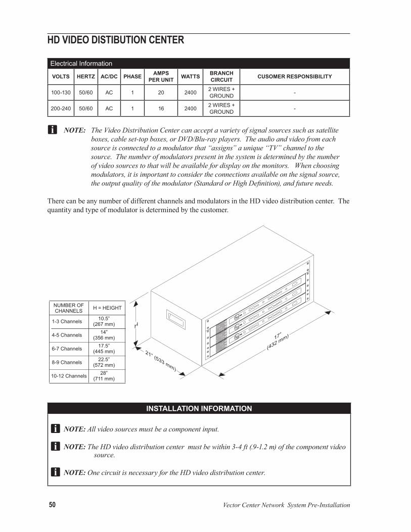
hd Video diStiButioN CeNter
Electrical Information
volts Hertz Ac/dc pHAse AMpsper unit wAtts brAncH
circuit cusoMer responsibility
100-130 50/60 AC 1 20 2400 2 WIRES + GROUND -
200-240 50/60 AC 1 16 2400 2 WIRES + GROUND -
NOTE:TheVideoDistributionCentercanacceptavarietyofsignalsourcessuchassatelliteboxes,cableset-topboxes,orDVD/Blu-rayplayers.Theaudioandvideofromeachsourceisconnectedtoamodulatorthat“assigns”aunique“TV”channeltothesource.Thenumberofmodulatorspresentinthesystemisdeterminedbythenumberofvideosourcestothatwillbeavailablefordisplayonthemonitors.Whenchoosingmodulators,itisimportanttoconsidertheconnectionsavailableonthesignalsource,theoutputqualityofthemodulator(StandardorHighDefinition),andfutureneeds.
There can be any number of different channels and modulators in the HD video distribution center. The quantity and type of modulator is determined by the customer.
instAllAtion inforMAtion
NOTE:Allvideosourcesmustbeacomponentinput.
NOTE:TheHDvideodistributioncentermustbewithin3-4ft(.9-1.2m)ofthecomponentvideosource.
NOTE: OnecircuitisnecessaryfortheHDvideodistributioncenter.

Vector Center Network System Pre-Installation 51
CoNtrol deSkElectrical Information
volts Hertz Ac/dc pHAse AMpsper unit wAtts brAncH
circuit cusoMer responsibility
100-130 50/60 AC 1 20 2640 2 WIRES + GROUND INSTALL CIRCUIT WITH APPROPRIATE
RECEPTACLE. 200-240 50/60 AC 1 16 2640 2 WIRES +
GROUND
instAllAtion inforMAtion
custoMer’s responsibility: THE CONTROL DESk SHOWN IS AN ExAMPLE OF A TWO TERMINAL CONTROL DESk. THE CONTROL DESk LAyOUT VARIES WITH INDIVIDUAL BOWLING CENTERS. THE DECISION OF EQUIPMENT LOCATIONS SHOULD BE MADE BEFORE POWER OUTLETS AND CONDUITS ARE INSTALLED. PLEASE PROVIDE OUTLES IN SIMILIAR CONFIGURATION AS SHOWN.
NOTE: TheCPUmustbewithin3-4ft(.9-1.2m)oftheterminalandprinter.
NOTE: TwocircuitsarenecessaryforeverythingattheControlDesk.

52 Vector Center Network System Pre-Installation
offiCeElectrical Information
volts Hertz Ac/dc pHAse AMpsper unit wAtts brAncH
circuit cusoMer responsibility
100-130 50/60 AC 1 13.5 1680 2 WIRES + GROUND INSTALL CIRCUIT WITH APPROPRIATE
RECEPTACLE. 200-240 50/60 AC 1 6.75 1680 2 WIRES +
GROUND
instAllAtion inforMAtion
custoMer’s responsibility: INSTALL ONE CIRCUIT WITH TWO EACH RECEPTACLES WITHIN THREE FEET (914 MM) OF THE UPS AND COMPUTER.

Vector Center Network System Pre-Installation 53
poiNt of Sale termiNalElectrical Information
volts Hertz Ac/dc pHAse AMpsper unit wAtts brAncH
circuit cusoMer responsibility
100-130 50/60 AC 1 8 1440 2 WIRES + GROUND
NO MORE THAN 2 POINT OF SALE TERMINALS PER CIRCUIT
200-240 50/60 AC 1 4 1440 2 WIRES + GROUND
NO MORE THAN 3 POINT OF SALE TERMINALS PER CIRCUIT
instAllAtion inforMAtion
custoMer’s responsibility: THE POINT OF SALE TERMINAL CAN BE LOCATED IN VARIOUS AREAS OF THE BOWLING CENTER. THEy ARE TyPICALLy IN THE LOUNGE, SNACk BAR, PRO SHOP, OR BILLIARDS AREA. THE ELECTRICAL CONFIGURATION IS THE SAME FOR EACH LOCATION, A SUITABLE LOW VOLTAGE RACEWAy MUST BE INSTALLED FOR COMMUNICATION CABLES.

54 Vector Center Network System Pre-Installation
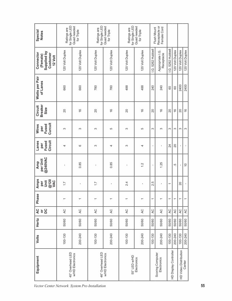
Sum
mar
y of
Ele
ctri
cal I
nfor
mat
ion
equi
pmen
tvo
ltsH
ertz
Ac
or
dc
phas
eA
mps
pe
r u
nit
@12
0 vA
c
Am
p pe
r uni
t @
240v
Ac
lane
s pe
r fu
sed
circ
uit
wire
s pe
r fu
sed
cur
cuit
circ
uit
bre
aker
si
ze
wat
ts p
er p
air
of l
anes
con
nect
or
(fem
ale)
su
pplie
d by
c
usto
mer
12 v
olt
spec
ial
not
es
32” O
verh
ead
LED
w
/SD
Ele
ctro
nics
100-
130
50/6
0AC
11.
2-
83
2033
612
0 Vo
lt D
uple
xR
atin
gs a
re
only
for D
oubl
e LE
Ds
Qua
d ne
ed fo
r Trip
le20
0-24
050
/60
AC1
-0.
712
316
336
120
Volt
Dup
lex
40” O
verh
ead
LED
w
/SD
Ele
ctro
nics
100-
130
50/6
0AC
11.
2-
43
2060
012
0 Vo
lt D
uple
xR
atin
gs a
re
for S
ingl
e LE
D
Qua
d ne
eded
fo
r Trip
le20
0-24
050
/60
AC1
-0.
76
316
600
120
Volt
Dup
lex
46” O
verh
ead
LED
w
/SD
Ele
ctro
nics
100-
130
50/6
0AC
11.
2-
33
2072
012
0 Vo
lt D
uple
xR
atin
gs a
re
for S
ingl
e LE
D
Qua
d ne
eded
fo
r Trip
le20
0-24
050
/60
AC1
-.0
76
316
720
120
Volt
Dup
lex
55” L
ED w
/SD
El
ectro
nics
100-
130
50/6
0AC
11.
9-
33
2033
012
0 Vo
lt D
uple
xR
atin
gs a
re
for S
ingl
e LE
D
Qua
d ne
eded
fo
r Trip
le20
0-24
050
/60
AC1
-.9
54
516
330
120
Volt
Dup
lex
32” O
verh
ead
LED
w
/HD
Ele
ctro
nics
100-
130
50/6
0AC
11.
7-
63
2042
012
0 Vo
lt D
uple
xR
atin
gs a
re
for S
ingl
e LE
D
Qua
d ne
eded
fo
r Trip
le20
0-24
050
/60
AC1
-0.
8510
316
420
120
Volt
Dup
lex
Vector Center Network System Pre-Installation 55
equi
pmen
tvo
ltsH
ertz
Ac
or
dc
phas
eA
mps
pe
r u
nit
@12
0 vA
c
Am
p pe
r uni
t @
240v
Ac
lane
s pe
r fu
sed
circ
uit
wire
s pe
r fu
sed
cur
cuit
circ
uit
bre
aker
si
ze
wat
ts p
er p
air
of l
anes
con
nect
or
(fem
ale)
su
pplie
d by
c
usto
mer
12 v
olt
spec
ial
not
es
40” O
verh
ead
LED
w
/HD
Ele
ctro
nics
100-
130
50/6
0AC
11.
7-
43
2066
012
0 Vo
lt D
uple
xR
atin
gs a
re
for S
ingl
e LE
D
Qua
d ne
eded
fo
r Trip
le20
0-24
050
/60
AC1
-0.
856
316
660
120
Volt
Dup
lex
46” O
verh
ead
LED
w
/HD
Ele
ctro
nics
100-
130
50/6
0AC
11.
7-
33
2078
012
0 Vo
lt D
uple
xR
atin
gs a
re
for S
ingl
e LE
D
Qua
d ne
eded
fo
r Trip
le20
0-24
050
/60
AC1
-0.
854
516
780
120
Volt
Dup
lex
55” L
ED w
/HD
El
ectro
nics
100-
130
50/6
0AC
12.
4-
33
2048
812
0 Vo
lt D
uple
xR
atin
gs a
re
for S
ingl
e LE
D
Qua
d ne
eded
fo
r Trip
le20
0-24
050
/60
AC1
-1.
24
516
488
120
Volt
Dup
lex
Sco
ring
Com
pute
rEl
ectro
nics
100-
130
50/6
0AC
12.
5-
-3
2024
0I.G
. 526
2 H
ubbe
llFl
ush
Mou
nt
Rec
epta
cle
or
Fem
ale
Cor
d20
0-24
050
/60
AC1
-1.
25-
316
240
App
ropr
iate
I.G
. R
ecep
tacl
e
HD
Dis
play
Con
trolle
r10
0-13
050
/60
AC1
124
320
60I.G
. 526
2 H
ubbe
ll
200-
240
50/6
0AC
1.5
203
1660
120
Volt
Dup
lex
HD
Vid
eo D
istri
butio
n C
ente
r10
0-13
050
/60
AC1
20-
-3
2024
0012
0 Vo
lt D
uple
x
200-
240
50/6
0AC
1-
10-
316
2400
120
Volt
Dup
lex

56 Vector Center Network System Pre-Installation
equi
pmen
tvo
ltsH
ertz
Ac
or
dc
phas
eA
mps
pe
r u
nit
@12
0 vA
c
Am
p pe
r uni
t @
240v
Ac
lane
s pe
r fu
sed
circ
uit
wire
s pe
r fu
sed
cur
cuit
circ
uit
bre
aker
si
ze
wat
ts p
er p
air
of l
anes
con
nect
or
(fem
ale)
su
pplie
d by
c
usto
mer
12 v
olt
spec
ial
not
es
Clie
nt C
ompu
ter
100-
130
50/6
0AC
15
--
320
600
120
Volt
Dup
lex
200-
240
50/6
0AC
1-
2.5
-3
1660
012
0 Vo
lt D
uple
x
Ser
ver C
ompu
ter
100-
130
50/6
0AC
16
--
320
960
120
Volt
Dup
lex
500
VA U
PS
Sup
plie
s Po
wer
200-
240
50/6
0AC
1-
3-
316
960
120
Volt
Dup
lex
Poin
t of S
ale
Term
inal
100-
130
50/6
0AC
1-
--
320
2880
120
Volt
Dup
lex
Qua
d R
ecep
tacl
e20
0-24
050
/60
AC1
-6
-3
1628
8012
0 Vo
lt D
uple
x
Tel -
E-Fo
ul10
0-13
050
/60
AC1
13.5
675
103
2012
012
0 Vo
lt D
uple
xD
uple
x R
ecep
tacl
e20
0-24
050
/60
AC1
-.5
103
1612
012
0 Vo
lt D
uple
x
Ligh
twor
x10
0-13
050
/60
AC1
1-
103
2012
012
0 Vo
lt D
uple
xD
uple
x R
ecep
tacl
e20
0-24
050
/60
AC1
-.5
103
1612
012
0 Vo
lt D
uple
x
Auto
mat
ed B
umpe
rs
100-
130
50/6
0AC
13
-8
320
360
I.G. 5
262
Hub
bell
Qua
d D
uple
x pe
r Circ
uit
200-
240
50/6
0AC
1-
1.5
83
1636
0A
pprp
riate
I.G
. R
ecep
tacl
e
Scoresheet/O
ffice
Prin
ter
100-
130
50/6
0AC
16
-20
Rec
epta
cle
Dup
lex
Rec
epta
cle
200-
240
50/6
0AC
1-
320
rece
tacl
e
Com
pute
r M
onito
r10
0-13
050
/60
AC1
1.5
-16
Rec
epta
cle
Dup
lex
Rec
epta
cle
200-
240
50/6
0AC
10.
7516
Rec
etac
le

Vector Center Network System Pre-Installation 57
Lighting Specifications IMPORTANT: Failure to comply with lighting specifications may adversely affect the
performance of your electronic equipment.
Of all the “mental hazards” in the design of a bowling center, lane lighting is recognized as one of the most important, yet it is often skipped over in the interest of saving the cost, effort, or time involved in a proper analysis of the problem. Each installation has individual problems and is worthy of considerable study. It is recommended that time be taken to review the following lighting specifications carefully.
oBjeCtiVeSThere are certain constraints and suggestions worth passing on to a bowling center. First, the need for even light intensity on the lanes is paramount. Over the high reflective playing surface, extreme care must be taken to avoid “hot spots” of illumination. In addition to careful planning of the spacing of lights, if “hot spots” do occur, they can usually be washed out by tilting or shimming the light fixtures before they are permanently fastened.
iN SummaryIn general, what the above recommendations are trying to accomplish is a gradual increase of light level from low in the seating area, to high on the pins. The pins should have the bowler’s attention.
Air conditioning heat load is also a factor in planning the lights. Each watt hour of light introduces 3.4 BTU of heat which must be taken into consideration for the air conditioning equipment. Excessive high humidity can also unfavorably affect the operation of some fluorescent lamps.
operatioNIt is desirable to control lane lighting longitudinally in bays of four lanes per switch at the Control Desk. A more compact panel board can be planned if the electrician uses low voltage from the Control Desk to activators at the light panel. Brunswick suggests tamper-proof switches for lighting in the public areas, or switching public area lighting from circuit breaker panels.
Group replacement of lamps on a regular basis insures a high level of light output for the same current costs and minimizes bowling delays due to a defective or blown out lamp.
plaNNiNgCorrelate the light plan with the reflected acoustic ceiling plan and also with the layout of air conditioning ducts, louvers, grills, and thermostats.
Electrical conduit or raceways of adequate size should be imbedded in the concrete to provide for Vector cabling.

58 Vector Center Network System Pre-Installation
light leVelS
footcandlesConcourse, spectator area, or other public space illumination intensity is optional, but the location and type of fixture and intensity must be subject to the restriction of not washing out the score image. Illumination of 10-30 footcandles from flush-mounted or recessed ceiling fixtures is recommended. There should be no direct exposure of light sources into the seating and approach areas.
Bowlers’ Area (Suggested 10-15 Footcandles)General lighting intensity in the bowlers’ seating area should be 10-15 footcandles. Use of recessed ceiling fixtures (fluorescent single lamp) will provide the recommended zone light levels.
Special consideration should be given to the color treatment of walls and ceiling, and to the use of low-reflective carpet or tile in the seating area.
Approach (Suggested 5-10 Footcandles)Approach lighting intensity should be 5-10 footcandles. This level can be obtained through incidental light from the seating area and lane surface. If additional approach lighting is used, it should be separately switched from the Control Desk or on dimmer controls.
Lane Surface (Required 15-20 Footcandles)Lane surface illumination level should be 15-20 footcandles of even diffused lighting measured at floor level. The amount of incident light directly illuminating the masking units should be 10-15 footcandles.
Pinsetter Area (Suggested 30-35 Footcandles)While proper pin lighting is installed on the automatic pinsetter, general lighting in the pinsetter area should be about 35 footcandles of even illumination over the machines for servicing.
Mechanic’s Work Area (Suggested 75-100 Footcandles)The mechanic’s work area should have 75-100 footcandles in the bench area.
Pin Light SpecificationsFor Brunswick “A” and A-2 Pinsetters, the pin lights should be 40 watt, soft white or cool white tubes. For AMF Pinspotters, the pin lights should be 30 watt, soft white or cool white tubes. The pin light reflectors should be cleaned and, if necessary, painted prior to the arrival of the Brunswick Field Engineer to allow optimum light required for proper scoring.

Vector Center Network System Pre-Installation 59
Ultra-Violet (UV) or Black Light Bulbs
Ultra-violet light is measured differently than white light. Ultra-violet light releases very little visible light to the human eye. Instead, an ultra-violet light emits mostly ultra-violet (UV), which cannot be seen and blocks the visible light that can be seen.
White light is measured in watts. Ultra-violet light is measured in nanometers. A high quality effective ultra-violet light for bowling centers to have a “glowing” in the environment is long wave, 315 to 380 nanometers. Ultra-violet light bulbs are typically made using mercury vapor lamps or specially designed LED lights
Brunswick recommends florescent light bulbs, manufacturer part number is “F32T8-BLB”. If these types of light bulb are not preferred by the customer, seek professional advisement from a lighting engineer
NOTE: BrunswickdoesNOTrecommendincandescentlightbulbs.DoNOTmistakethiswith“F32T8-BL”.The“BLB”andthe“BL”bulbaredifferentlightsandwillnotperformthesame.
IMPORTANT: Failure to comply with Brunswick recommendations will drastically affect the “glowing” environment in the bowling centers.
Light Fixture ConfigurationWhen designing the lighting use a dual light fixture, with one white light and one ultra-violet bulb in the light fixture. Have a power on/off switch for the white light and another separate on/off switch for the ultra-violet light. This will allow the location and the placement of the white and ultra-violet light bulb the same to allow for an even light level intensity on the lanes.

60 Vector Center Network System Pre-Installation
light loCatioNS

Vector Center Network System Pre-Installation 61
Equipment DimensionspedeStalS

62 Vector Center Network System Pre-Installation
led oVerhead moNitorS

Vector Center Network System Pre-Installation 63

64 Vector Center Network System Pre-Installation
CirCular Ball raCkS
Vector Center Network System Pre-Installation 65
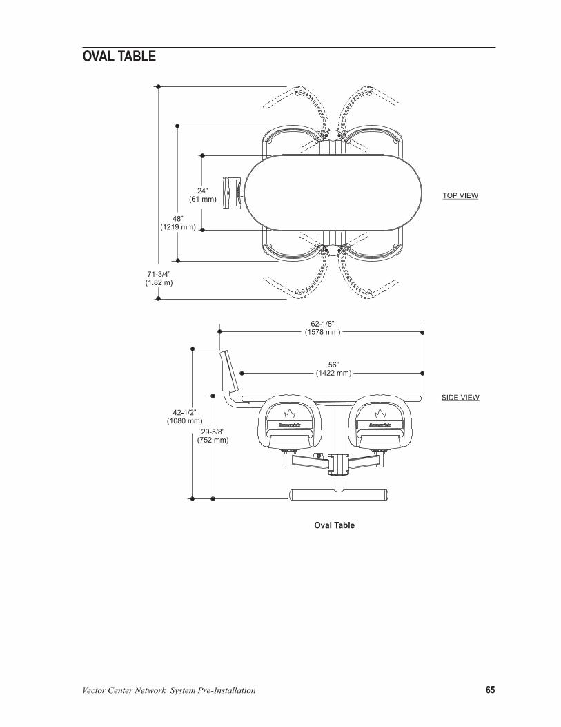
oVal taBle

66 Vector Center Network System Pre-Installation
triaNgle taBle

Vector Center Network System Pre-Installation 67
Coffee taBle
68 Vector Center Network System Pre-Installation
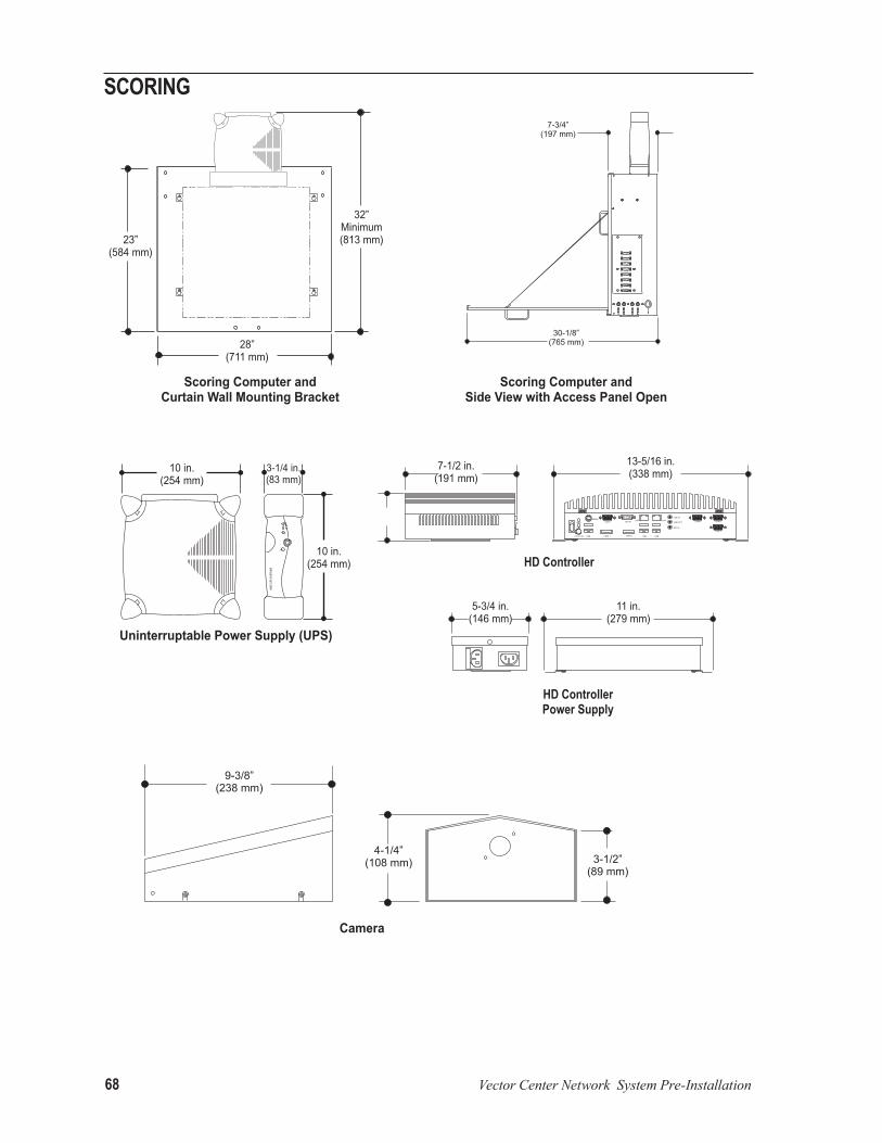
SCoriNg

Vector Center Network System Pre-Installation 69
CeNter maNagemeNt SyStem
1-3/4”(44 mm)
4-1/4”(108 mm)
9”(228 mm)
16-1/2”(419 mm)
8-1/2”(216 mm)
6-1/4”(159 mm)
5-3/4”(146 mm)
Receipt Printer
Customer Display
POWER
ERROR
FEED
Optional 19” Touch ScreenPoint of Sale Terminal and Cash Drawer
20”(508 mm)
4-1/2”(114 mm)
19” in.(483 mm)
Optional 17” Touch ScreenPoint of Sale Terminal and Cash Drawer
20”(508 mm)
7”(178 mm)
21-1/2”(546 mm)
9”(228 mm)
17”(432 mm)
9”(228 mm)
4-1/2”(114 mm)
17”(431 mm)
19”(483 mm)
17-1/4”(438 mm)
10”(254 mm)
18”(457 mm)
22-1/2”(572 mm)
7”(178 mm)
8-1/4”(210 mm)

70 Vector Center Network System Pre-Installation

Vector Center Network System Pre-Installation 71
miSCellaNeouS

72 Vector Center Network System Pre-Installation
Intentionally Blank

Certificates73
I, by signing this document, certify to Brunswick Bowling and Billiards Corporation and to the proprietor named below that:
1. I am an engineer/architect licensed by and in good standing with the State of ______________________; and
2. I have examined the bowling center premises known as __________________________________________ ,
located at ___________________________________________________________________________ ; and
3. Thecurtainwallstructureofthebowlingcenterisfullyandsafelycapableofsupportingtheconfigurationofcurtain wall electronic units, not exceeding 100 pounds actual/static weight for each scoring computer to be at-tachedtothecurtainwallorsuitablestructurebythemeansandmethodssetforthinthesupportspecificationson the reverse side of this sheet.
Curtain Wall Structure Certification
Certification and Release of Brunswick by Proprietor
I, __________________________________________, as the proprietor or as duly-authorized representative of the pro-prietor, certify to Brunswick Bowling and Billiards Corporation that:
1. TheproprietorhasobtainedtheaboveStructureCertificationfortheproprietor'sownbenefit;and 2. The proprietor is not relying upon Brunswick for assurance that the curtain wall or suitable structure described
intheStructureCertificationwillsupportthecurtainwallelectronicunitsselectedbytheproprietorandin-stalled by Brunswick.
In consideration for Brunswick’s agreement to install the curtain wall electronic units, and by signing below, proprietor forproprietor'sownselfandforproprietor'sheirs,successors,assigns,employees,agents,representatives,insurers,contractors, subcontractors, invitees, and their spouses and relatives (“Proprietor Group”), releases and agrees to indem-nifyBrunswick,itsofficers,directors,employees,shareholders,parentcompany,subsidiaries,andaffiliatedcompanies,insurers, agents, contractors, and subcontractors from all claims, demands, actions, causes of action, or their functional equivalent, that any member of the Proprietor Group may have or which may subsequently accrue to a member of the Proprietor Group arising out of or connected with, directly or indirectly, the inability of the curtain wall or suitable struc-turedescribedintheaboveStructureCertificationtosupportthecurtainwallelectronicunitsinstalledbyBrunswickinaccordancewiththesupportspecificationsonthereversesideofthissheet.
PrintorTypeNameofProprietororCorporateOfficer Signature
Title
Date
Print or Type Name of Architect or Structural Engineer
Signature of Architect or Structural Engineer
Title
Seal Date
Send To:Contract ManagementBrunswick Bowling and Billiards CorporationPost Office Box 329Muskegon, MI 49443-0329or Fax: 231-725-3364

74 Certificates
Using the preferred method of support for the curtain wall electronics, the customer is responsible for supply-ing, installing, and maintaining the proper position of the electronics located on the curtain wall. If a cur-tain wall is not available, a support structure must be installed to accommodate the 100 pounds actual/static weight load per lane pair.
Curtain Wall Structure Support Specifications
CurtainWallMounting

Certificates75
Print or Type Name of Architect or Structural Engineer
Signature of Architect or Structural Engineer
Title
Seal Date
Wide Screen LED Overhead Video Display Structure Certification
NUMBER OF SINGLE WELDMENTSMONITOR
SIZEQTY LBS KG TOTAL
WEIGHT
32" 102.0 46.3
40" 110.4 50.1
46" 117.0 53.4
55" 134.4 61.0TOTAL
Certification & Release of Brunswick by Architect/Structural EngineerI, by signing this document, certify to Brunswick Bowling & Billiards Corporation and to the proprietor named below, that:
1. I am an engineer/architect licensed by and in good standing with the State of ____________________________________________; and
2. I have examined the bowling center premises known as ________________________________________________________________;
located at; _________________________________________________________________________________________________; and
3. The roof structure of the bowling center is fully and safely capable of supporting the additional static weight for each LED Overhead Video Display unit as indicated in Figure 1. Display support to be attached to the roof structure by the means and methods set forth in the supportspecificationsonthereversesideofthispage.
NOTE:ItistheBrunswicksalesman'sresponsibilitytoverifythequantitycolumn(s)inFigure1.
Figure1.LEDandWideScreenStructureType.
PrintorTypeNameofProprietororCorporateOfficer
Signature
Title
Date
Certification & Release of Brunswick by ProprietorI, __________________________________________, as the proprietor or as duly-authorized representative of the proprietor, certify to Brunswick Bowling and Billiards Corporation that: 1. TheproprietorhasobtainedtheaboveStructureCertificationfortheproprietor'sownbenefit;and 2. TheproprietorisnotrelyinguponBrunswickforassurancethattheroofstructuredescribedintheStructureCertificationwillsupportthe
LED Overhead Video Display units selected in Figure 1 by the proprietor and installed by Brunswick. 3. The proprietor will not hang anything other than the Brunswick-provided video displays from the display supports, and will monitor the
bowling center to ensure that customers of the center do not hang or place weight in any way on the display supports.
In consideration of Brunswick’s agreement to install the LED Overhead Video Display units indicated in Figure 1, and by signing below, proprietor, for proprietor’s own self and for proprietor’s heirs, successors, assigns, employees, agents, representatives, insurers, contractors, subcontractors, invitees,andtheirspousesandrelatives(“ProprietorGroup”),releasesandagreestoindemnifyandholdharmlessBrunswick,itsofficers,direc-tors,employees,shareholders,parentcompany,subsidiaries,andaffiliatedcompanies,insurers,agents,contractorsandsubcontractors(collectively,“Brunswick”) from all liability, claims, demands, actions, causes of action, or their functional equivalent, that any member of the Proprietor Group or Brunswick may have or may subsequently accrue to any member of the Proprietor Group or Brunswick arising out of or connected with, directly or indirectly,(i)theinabilityoftheroofstructuredescribedintheStructureCertificationtosupporttheLEDOverheadVideoDisplayunitsindicatedinFigure 1 andinstalledbyBrunswickinaccordancewiththesupportspecificationsonthereversesideofthissheet,or(ii)theinabilityofthedisplaysupports to support any weight placed upon it in excess of the weight of the Brunswick-provided video displays.
Send To:Contract ManagementBrunswick Bowling and Billiards CorporationPost Office Box 329Muskegon, MI 49443-0329or Fax: 231-725-3364
NUMBER OF DOUBLE WELDMENTSMONITOR
SIZEQTY LBS KG TOTAL
WEIGHT
32" 135.6 61.6
40" 159.6 72.5
46" 174.0 79.0
55" 180.0 81.7TOTAL
NUMBER OF TRIPLE WELDMENTSMONITOR
SIZEQTY LBS KG TOTAL
WEIGHT
32" 177.6 80.6
40" 202.8 92.1
46" 224.4 101.9
55" N.A.TOTAL

76 Certificates
Wide Screen LED Overhead Video Display Support Specifications
The customer is responsible for supplying, installing, and maintaining the proper position of these beams orpipe(refertofiguresbelow)andforhavingcertificationfromanarchitectorstructuralengineerthatthemethod of support will be capable of supporting an additional weight actual/static per lane pair for up to triple overheads.
SideView
TopView

Certificates77
Customer Purchased Overhead Monitor Waiver of Liability and Hold Harmless Agreement
RecitalsWHEREAS, Brunswick and Buyer have entered into that certain Sales Contract No. __________ (the “Sales Contract”);
WHEREAS, Brunswick and Buyer have entered into that certain Installation Contract No._______________ (the “Installation Contract”);
WHEREAS, Buyer has requested that Brunswick permit Buyer to self-install the overheads monitors and hanging support structure purchased to the Sales Contract;
WHEREAS, Brunswick will permit Buyer to self-install such equipment, if Buyer agrees to indemnify Brunswick and waive any claims against Brunswick arising from or related to the installation of such equipment pursuant to this Agreement.
AgreementFOR VALUABLE CONSIDERATION, the receipt of which is hereby acknowledged, Buyer hereby agrees as follows:
Buyer acknowledges that it has been advised by Brunswick as to the risks involved in self-installing overheads monitors and hanging support structure, and Buyer understands that it is solely responsible for ascertaining the proper installation, accepts the potential risks and waives any warranty claims on such overheads monitors and hanging support structure.
Buyer and its successors, and assigns, assume the entire responsibility and liability for, covenant not to sue, and will protect,indemnify,defend,andholdharmlessBrunswick,itsofficers,directors,employees,agents,representatives,shareholders,insurers,subsidiaryandaffiliatedcompanies,successors,andassignsfromandagainstallliabilities,losses,expenses, costs, penalties, forfeitures, suits, actions, demands, pending or threatened claims, proceedings or their func-tional equivalent or causes of action of whatever nature or character as well as all related costs and expenses including, withoutlimitation,reasonableattorneys'feesandcourtcosts,madeagainstBrunswick,itsofficers,directors,agents,representatives, employees, successors, or assigns for any reason whatsoever including, without limitation, any injury, death, monetary loss or governmental violation, actual or alleged, arising out of or resulting from the installation of the overheads monitors and hanging support structure by Buyer.
This Agreement shall be interpreted under the laws of the State of Illinois.
IN WITNESS WHEREOF,thepartieshaveexecutedthisAgreementasofthedateandyearfirstwrittenabove.
BRUNSWICK BOWLING & BILLIARDS CORPORATION BUYER__________________________________
By: _______________________________
Its: _______________________________
_________________________________
This Waiver of Liability and Hold Harmless Agreement (this “Agreement”) is dated as of _______________, by and between Brunswick Bowling & Billiards Corporation, a Delaware corporation (“Brunswick”) and _____________ (“Buyer”).
By: ______________________________
Its: ______________________________