vector inverter
DESCRIPTION
DescriptionEspecialistas en :Máquinas eléctricas. Control de procesos industriales.Control neumático e hidráulico. Sistemas de distribución y potencia.Programación de mantenimiento eléctrico. Control automático.Controladores Lógicos programables PLC. Instalaciones eléctricas residenciales e industriales.Electrónica.Experiencia en :Variadores de frecuencia de ALLEN BRADLEY.Telemecanique. LG. ABB. HITACHI L300P. RELIANCEDELTA.PLC simatic S7-300 de SIEMENS. LOGO de SIEMENS.PLC Zelio de Telemecanique.OMRON. CX ProgrammerALLEN BRADLEY SLC 500 PLC 5 MICROLOGIX 1000 ,1200.MITSUBISBHI ELECTRIChttp://www.antechsv.4t.com/TRANSCRIPT

VECTOR INVERTER
VECTOR INVERTER

08/2003
FREQUENCY
INVERTER
MANUAL
Series: CFW-08
Software: version 3.9X
0899.4690 E/5
ATTENTION!
It is very important to check if the
inverter software version is the
same as indicated above.

Summary of Revisions
The table below describes all revisions made to this manual.
Revision Description Section1 First Edition -
2 Item 3.3 - CE Installation Included See item 3.3
3 General Revision -
4External Parallel Keypad and
See item 8.3Fixs Kit Included and
and 8.12General Revision
5 General Revision -
6
Description changed of the Parallel Cable
See item 8.5for the External Parallel Keypad.
and 6.3.5Item 7.5 (Spare Part List) Removed.
Parameter 536 included
and General Revision
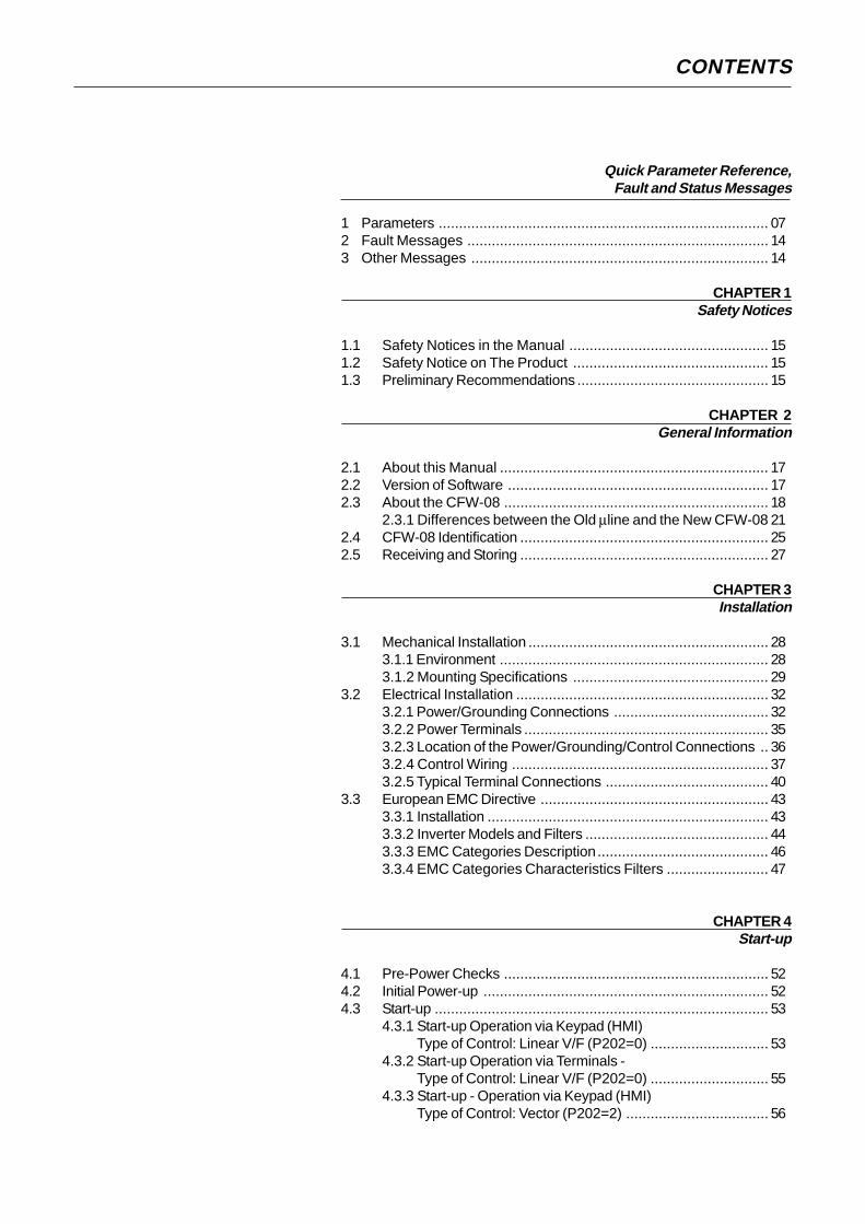
CONTENTS
Quick Parameter Reference,Fault and Status Messages
1 Parameters ................................................................................. 072 Fault Messages .......................................................................... 143 Other Messages ......................................................................... 14
CHAPTER 1Safety Notices
1.1 Safety Notices in the Manual ................................................. 151.2 Safety Notice on The Product ................................................ 151.3 Preliminary Recommendations ............................................... 15
CHAPTER 2General Information
2.1 About this Manual .................................................................. 172.2 Version of Software ................................................................ 172.3 About the CFW-08 ................................................................. 18
2.3.1 Differences between the Old µline and the New CFW-08 212.4 CFW-08 Identification ............................................................. 252.5 Receiving and Storing ............................................................. 27
CHAPTER 3Installation
3.1 Mechanical Installation ........................................................... 283.1.1 Environment .................................................................. 283.1.2 Mounting Specifications ................................................ 29
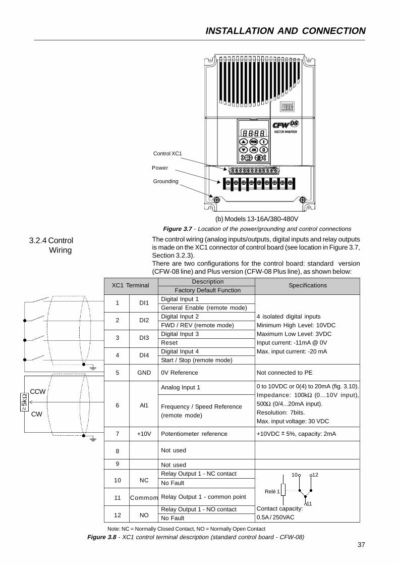
3.2 Electrical Installation .............................................................. 323.2.1 Power/Grounding Connections ...................................... 323.2.2 Power Terminals ............................................................ 353.2.3 Location of the Power/Grounding/Control Connections .. 363.2.4 Control Wiring ............................................................... 373.2.5 Typical Terminal Connections ........................................ 40
3.3 European EMC Directive ........................................................ 433.3.1 Installation ..................................................................... 433.3.2 Inverter Models and Filters ............................................. 443.3.3 EMC Categories Description.......................................... 463.3.4 EMC Categories Characteristics Filters ......................... 47
CHAPTER 4Start-up
4.1 Pre-Power Checks ................................................................. 524.2 Initial Power-up ...................................................................... 524.3 Start-up .................................................................................. 53
4.3.1 Start-up Operation via Keypad (HMI)Type of Control: Linear V/F (P202=0) ............................. 53
4.3.2 Start-up Operation via Terminals -Type of Control: Linear V/F (P202=0) ............................. 55
4.3.3 Start-up - Operation via Keypad (HMI)Type of Control: Vector (P202=2) ................................... 56

CONTENTS
CHAPTER 5Keypad (HMI) Operation
5.1 Keypad (HMI) Description ........................................................ 605.2 Use of the Keypad (HMI) .......................................................... 61
5.2.1 Keypad Operation ........................................................... 625.2.2 Inverter Status ................................................................. 635.2.3 Read-Only Variables ........................................................ 635.2.4 Parameter Viewing and Programming .............................. 64
CHAPTER 6Detailed Parameter Description
6.1 Symbols .................................................................................. 666.2 Introduction .............................................................................. 66
6.2.1 Control Modes ................................................................. 666.2.2 V/F Control ...................................................................... 666.2.3 Vector Control (VVC) ....................................................... 676.2.4 Frequency Reference Sources ........................................ 676.2.5 Commands...................................................................... 706.2.6 Local/Remote Operation Modes ...................................... 70
6.3 Parameter Listing ..................................................................... 716.3.1 Access and Read Only Parameters - P000...P099 .......... 726.3.2 Regulation Parameters - P100...P199 ............................. 736.3.3 Configuration Parameters - P200...P398.......................... 816.3.4 Motor Parameters - P399...P499 ................................... 1016.3.5 Special Function Paramaters - P500...P599 .................. 104
6.3.5.1 PID Introduction ............................................... 1046.3.5.2 PÌD Description ................................................ 1046.3.5.3 PID Start-up Guide ........................................... 106
CHAPTER 7Diagnostics and Troubleshooting
7.1 Faults and Possible Causes ................................................... 1107.2 Troubleshooting ....................................................................... 1127.3 Contacting WEG ..................................................................... 1137.4 Preventive Maintenance ........................................................... 113
7.4.1 Cleaning Instructions ...................................................... 114
CHAPTER 8CFW-08 Options and Accessories
8.1 HMI-CFW08-P......................................................................... 1168.1.1 Instructions for Insertion - Removing of HMI-CFW08-P .... 117
8.2 TCL-CFW08 ............................................................................ 1178.3 HMI-CFW08-RP ...................................................................... 117
8.3.1 HMI-CFW08-RP Installation ............................................ 1188.4 MIP-CFW08-RP ...................................................................... 1188.5 CAB-RP-1, CAB-RP-2, CAB-RP-3, CAB-RP-5, CAB-RP-7.5,
CAB-RP-10 ............................................................................. 1198.6 HMI-CFW08-RS ...................................................................... 119
8.6.1 HMI-CFW08-RS Installation ........................................... 1208.6.2 HMI-CFW08-RS Start-up ............................................... 1208.6.3 Keypad Copy Function .................................................. 121
8.7 MIS-CFW08-RS ..................................................................... 121
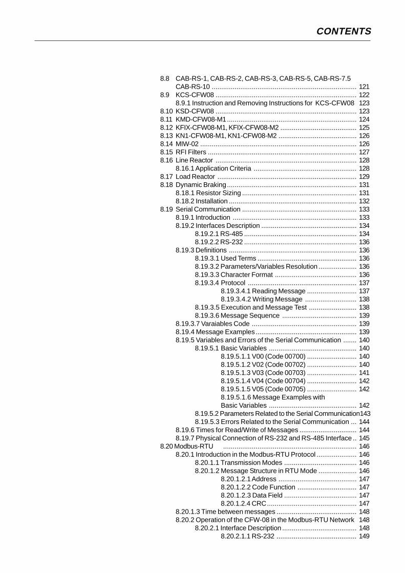
CONTENTS
8.8 CAB-RS-1, CAB-RS-2, CAB-RS-3, CAB-RS-5, CAB-RS-7.5CAB-RS-10 ............................................................................ 121
8.9 KCS-CFW08 .......................................................................... 1228.9.1 Instruction and Removing Instructions for KCS-CFW08 123
8.10 KSD-CFW08 .......................................................................... 1238.11 KMD-CFW08-M1.................................................................... 1248.12 KFIX-CFW08-M1, KFIX-CFW08-M2 ........................................ 1258.13 KN1-CFW08-M1, KN1-CFW08-M2 ......................................... 1268.14 MIW-02 .................................................................................. 1268.15 RFI Filters .............................................................................. 1278.16 Line Reactor .......................................................................... 128
8.16.1 Application Criteria ...................................................... 1288.17 Load Reactor ......................................................................... 1298.18 Dynamic Braking.................................................................... 131
8.18.1 Resistor Sizing ............................................................ 1318.18.2 Installation ................................................................... 132
8.19 Serial Communication ............................................................ 1338.19.1 Introduction ................................................................. 1338.19.2 Interfaces Description .................................................. 134
8.19.2.1 RS-485 ........................................................... 1348.19.2.2 RS-232 ........................................................... 136
8.19.3 Definitions ................................................................... 1368.19.3.1 Used Terms .................................................... 1368.19.3.2 Parameters/Variables Resolution .................... 1368.19.3.3 Character Format ........................................... 1368.19.3.4 Protocol ......................................................... 137
8.19.3.4.1 Reading Message .......................... 1378.19.3.4.2 Writing Message ........................... 138
8.19.3.5 Execution and Message Test ......................... 1388.19.3.6 Message Sequence ....................................... 139
8.19.3.7 Varaiables Code ....................................................... 1398.19.4 Message Examples..................................................... 1398.19.5 Variables and Errors of the Serial Communication ....... 140
8.19.5.1 Basic Variables .............................................. 1408.19.5.1.1 V00 (Code 00700) .......................... 1408.19.5.1.2 V02 (Code 00702) .......................... 1408.19.5.1.3 V03 (Code 00703) .......................... 1418.19.5.1.4 V04 (Code 00704) .......................... 1428.19.5.1.5 V05 (Code 00705) .......................... 1428.19.5.1.6 Message Examples withBasic Variables .............................................. 142
8.19.5.2 Parameters Related to the Serial Communication1438.19.5.3 Errors Related to the Serial Communication ... 144
8.19.6 Times for Read/Write of Messages .............................. 1448.19.7 Physical Connection of RS-232 and RS-485 Interface .. 145
8.20 Modbus-RTU ...................................................................... 1468.20.1 Introduction in the Modbus-RTU Protocol ..................... 146
8.20.1.1 Transmission Modes ...................................... 1468.20.1.2 Message Structure in RTU Mode .................... 146
8.20.1.2.1 Address ......................................... 1478.20.1.2.2 Code Function ............................... 1478.20.1.2.3 Data Field ...................................... 1478.20.1.2.4 CRC............................................... 147
8.20.1.3 Time between messages .......................................... 1488.20.2 Operation of the CFW-08 in the Modbus-RTU Network 148
8.20.2.1 Interface Description ....................................... 1488.20.2.1.1 RS-232 .......................................... 149

CONTENTS
8.20.2.1.2 RS-485 .......................................... 1498.20.2.2 Inverter Configuration in the
Modbus-RTU Network ..................................... 1498.20.2.2.1 Inverter address in the Network ...... 1498.20.2.2.2 Transmission Rate and Parity ........ 149
8.20.2.3 Access to the Inverter Data ............................ 1498.20.2.3.1Available Functions andResponse Times ............................................ 1508.20.2.3.2 Register addressing and Offset ...... 150
8.20.3Detailed Function Description ...................................... 1528.20.3.1 Function 01 - Read Coils ................................ 1538.20.3.2 Function 03 - Read Holding Register .............. 1538.20.3.3 Function 05 - Write Single Coil ....................... 1548.20.3.4 Function 06 - Write Single Register ................ 1558.20.3.5 Function 15 - Write Multiple Coils ................... 1558.20.3.6 Function 16 - Write Multiple Registers ............ 1568.20.3.7 Function 43 - Read Device Identification ......... 157
8.20.4Communication Errors ................................................. 1598.20.4.1 Error Messages .............................................. 159
CHAPTER 9Technical Specifications
9.1 Power Data ............................................................................ 1619.1.1 200 - 240V Power Supply .............................................. 1619.1.2 380 - 480V Power Supply .............................................. 161
9.2 General Electronic Data ......................................................... 1639.3 WEG Standard IV Pole Motor Data ........................................ 164
CHAPTER 10Warranty
Warranty Terms for Frequency Inverters - CFW-08 ........................ 165
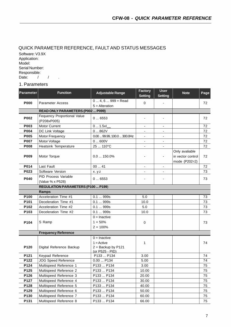
7
CFW-08 - QUICK PARAMETER REFERENCE
Software: V3.9XApplication:Model:Serial Number:Responsible:Date: / / .
1. Parameters
Parameter Function Adjustable RangeFactory User
Note PageSetting Setting
P000 Parameter Access0 ... 4, 6 ... 999 = Read
0 - 725 = Alteration
READ ONLY PARAMETERS (P002 ... P099)
P002Fequency Proportional Value
0 ... 6553 - - 72(P208xP005)
P003 Motor Current 0 ... 1.5xInom - - 72P004 DC Link Voltage 0 ... 862V - - 72
P005 Motor Frequency 0.00 ... 99.99, 100.0 ... 300.0Hz - - 72P007 Motor Voltage 0 ... 600V - - 72P008 Heatsink Temperature 25 ... 110°C - - 72
P009 Motor Torque 0.0 ... 150.0% - -Only avaliablein vector control 72mode (P202=2)
P014 Last Fault 00 ... 41 - - 72
P023 Software Version x . y z - - 73
P040PID Process Variable
0 ... 6553 - - 73(Value % x P528)
REGULATION PARAMETERS (P100 ... P199)Ramps
P100 Acceleration Time #1 0.1 ... 999s 5.0 73
P101 Deceleration Time #1 0.1 ... 999s 10.0 73P102 Acceleration Time #2 0.1 ... 999s 5.0 73P103 Deceleration Time #2 0.1 ... 999s 10.0 73
P104
0 = Inactive
0 73S Ramp 1 = 50%2 = 100%
Frequency Reference0 = Inactive
1 = Active 1 74P120 Digital Reference Backup 2 = Backup by P121
(or P525 - PID)P121 Keypad Reference P133 ... P134 3.00 74P122 JOG Speed Reference 0.00 ... P134 5.00 74
P124 Multispeed Reference 1 P133 ... P134 3.00 75P125 Multispeed Reference 2 P133 ... P134 10.00 75P126 Multispeed Reference 3 P133 ... P134 20.00 75
P127 Multispeed Reference 4 P133 ... P134 30.00 75P128 Multispeed Reference 5 P133 ... P134 40.00 75P129 Multispeed Reference 6 P133 ... P134 50.00 75
P130 Multispeed Reference 7 P133 ... P134 60.00 75
P131 Multispeed Reference 8 P133 ... P134 66.00 75
QUICK PARAMETER REFERENCE, FAULT AND STATUS MESSAGES

8
CFW-08 - QUICK PARAMETER REFERENCE
Speed LimitsP133 Minimum Frequency (Fmin) 0.00 ... P134 3.00 76
P134 Maximum Frequency (Fmax) P133 ... 300.0Hz 66.00 76V/F Control
P136 Manual Torque Boost0.0 ... 30.0%
5.0 or
Only available
76(IxR Compensation)2.0 or
in V/F control
1.0 (2)
Control ModeP137
Aut. Torque Boost0.00 ... 1.00 0.00
P202=0 or 1.
76(aut. IxR compensation)
P138 Slip Compensation 0.0 ... 10.0% 0.0 77P142 (1) Maximum Output Voltage 0.0 ... 100% 100 78
P145 (1) Field WeakeningP133 ... P134
50.00Hz or
78Frequency (Fnom)
60.00Hzdepending
on themarket
DC Link Voltage Regulation
P151 DC Link Regulation Level200V models: 325 ... 410V 380V
79400V models: 564 ... 820V 780V
Overload CurrentP156 Motor Overload Current 0.2xInom ... 1.3xInom 1.2xP401 79
Current LimitationP169 Maximum Output Current 0.2xInom ... 2.0xInom 1.5xInom 80
Flux Control
P178 50.0 ... 150% 100
Only available80
Rated Flux in V/F control
mode (P202=2).CONFIGURATION PARAMETERS (P200 ... P398)Generic Parameters
P202 (1) Control Mode
0 = Linear V/F Control
0 811 = Quadratic V/F Control2 = Sensorless Vector
P203 (1) Special Function Selection0 = No function
0 821 = PID Regulator
P204 (1) Load Factory Setting0 ... 4 = No Function
0 - 825 = Loads Factory Default
P205 Display Default Selection
0 = P005
2 82
1 = P003
2 = P0023 = P0074, 5 = Not used
6 = P040P206 Auto-Reset Time 0 ... 255s 0 82P208 Reference Scale Factor 0.00 ... 99.9 1.00 83
0 = Off
0
Only available
83P215 (1) Keypad Copy Function 1 = Copy (inverter to keypad) via HMI-CFW08-RS2 = Paste (keypad to inverter) keypad.
P219 (1) Switching Frequency0.00 ... 25.00Hz 6.00 84
Reduction Point(1) This parameter can be changed only with the inverter disabled (motor stopped).(2) The factory default of Parameter P136 depends on the inverter model as follows:
- models 1.6-2.6-4.0-7.0A/200-240V or 1.0-1.6-2.6-4.0A/380-480V: P136=5.0%;- models 7.3-10-16A/200-240V or 2.7-4.3-6.5-10A/380-480V: P136=2.0%;- models 13-16A/380-480V: P136=1.0%.
Parameter Function Adjustable RangeFactory User
Note PageSetting Setting

9
CFW-08 - QUICK PARAMETER REFERENCE
(1) This parameter can be changed only with the inverter disabled (motor stopped).
Only availablein CFW-08
Plus Version
Local/Remote Definition
P220 (1) Local/Remote
0 = Always Local
2 85Selection Source
1 = Always Remote2 = HMI-CFW08-P orHMI-CFW08-RP keypad
(default: local)3 = HMI-CFW08-P orHMI-CFW08-RP keypad
(default: remote)4 = DI2 ... DI45 = Serial or HMI-CFW08-RS
keypad (default: local)6 = Serial or HMI-CFW08-RSkeypad (default: remote)
0 = Keypad and
86
1 = AI12, 3 = AI2
P221 (1) Local Reference Selection 4 = E.P. (Electronic Pot.)0
5 = Serial6 = Multispeed
7 = Add AI>=08 = Add AI0 =Keypad and
86
1 = AI12, 3 = AI2
P222 (1) Remote Reference Selection 4 = E.P. (Eletronic Pot.)1
5 = Serial
6 = Multispeed7 = Add AI>=08 = Add AI
0 = HMI-CFW08-P or
86P229 (1) Local Command Selection HMI-CFW08-RP keypad
1 = Terminals0
2 = Serial or HMI-CFW08-RSkeypad0 = HMI-CFW08-P or
86P230 (1) Remote Command Selection HMI-CFW08-RP keypad
1 = Terminals1
2 = Serial or
HMI-CFW08-RS keypad
P231 (1) Forward/Reverse Selection0 = Forward
861 = Reverse 2
2 = CommandsAnalog Input(s)
P234 Analog Input AI1 Gain 0.00 ... 9.99 1.00 86
P235 (1)
Analog Input AI1 Signal0 = 0-10V/0-20mA
0 871 = 4-20mA
P236 Analog Input AI1 Offset -120 ... 120% 0.0 88
P238 Analog Input AI2 Gain 0.00 ... 9.99 1.00 88
P239 (1)
Analog Input AI2 Gain0 = 0-10V/0-20mA
0 871 = 4-20mA
P240 Analog Input AI2 Offset -120 ... 120% 0.0 88
P248Analog Inputs Filter
0 ... 200ms 200 88Time Constant
Parameter Function Adjustable RangeFactory User
Note PageSetting Setting

10
CFW-08 - QUICK PARAMETER REFERENCE
Only available in CFW-08
Plus version.
Analog Output0 = Output Frequency (Fs)
1 = Input Reference (Fe)
2 = Output Current (Is)
3, 5, 8 = Not used 88
P251 Analog Output 4 = Motor Torque 0AO Function 6 = Process Variable
(PID)
7 = Active Current9 = PID Setpoint
P252 Analog Output AO Gain 0.00 ... 9.99 1.00 88Digital Inputs
P263 (1) Digital Input DI1 Function
0 = No Function or
0 89
General Enable1 ... 7 and 10 ... 12 =
General Enable8 = Forward Run9 = Start/Stop
13 = FWD Run UsingRamp #214 = Start (3-wire)
P264 (1) Digital Input DI2 Function
0 = Forward/Reverse
0 89
1 = Local/Remote2 ... 6 and 9 ... 12 = Not used
7 = Multispeed (MS2)8 = Reverse13 = REV Run - Ramp #2
14 = Stop (3-wire)
P265 (1) (2) Digital Input DI3 Function
0 = Forward/Reverse
10 89
1 = Local/Remote
2 = General Enable3 = JOG4 = No External Fault
5 = Increase E.P.6 = Ramp #27 = Multispeed (MS1)
8 = No Function orStart/Stop9 = Start/Stop
10 = Reset11, 12 = Not used13 = Flying Start Disable
14 = Multispeed (MS1)Using Ramp #215 = Manual/Automatic PID)
16 = Increase E.P. withRamp #2
P266 (1) Digital Input DI4 Function
0 = Forward/Reverse
8 891 = Local/Remote2 = General Enable
(1) This parameter can be changed only with the inverter disabled (motor stopped).(2) Value may change as a function of P203.
Parameter Function Adjustable RangeFactory User
Note PageSetting Setting

11
CFW-08 - QUICK PARAMETER REFERENCE
Accordingto the
invertermodel
Only availablein CFW-08
Plus version.
In vector controlmode (P202=2)it is not possibleto set P297=7
(15kHz).
3 = JOG
4 = No Extrernal Fault5 = Decrease E.P.6 = Ramp #2
7 = Multispeed (MS0)8 = Not used orStart/Stop
9 = Start/Stop10 = Reset11, 12, 14 and 15 =
Not Used13 = Flying Start Disable16 = Decrease E.P. with
Ramp #2Digital Output(s)
P277 (1) Relay Output RL1 Function
0 = Fs>Fx
7 94
1 = Fe>Fx2 = Fs=Fe3 = Is>Ix
4 and 6 = Not used5 = Run7 = No Fault
P279 (1) Relay Output RL2 Function
0 = Fs>Fx
094
1 = Fe>Fx2 = Fs=Fe
3 = Is>Ix4 and 6 = Not used5 = Run
7 = No FaultFx and Ix
P288 Fx Frquency 0.00 ... P134 3.00 95
P290 Ix Current 0 ... 1.5xInom 1.0xInom 95Inverter Data
P295 (1) Rated Inverter
300 = 1.0A
95Current (Inom)
301 = 1.6A302 = 2.6A303 = 2.7A
304 = 4.0A305 = 4.3A306 = 6.5A
307 = 7.0A308 = 7.3A309 = 10A
310 = 13A311 = 16A
P297 (1) Switching Frequency
4 = 5.0kHz
4 965 = 2.5kHz6 = 10kHz7 = 15kHz
DC BrakingP300 DC Braking Time 0.0 ... 15.0s 0.0 97
Parameter Function Adjustable RangeFactory User
Note PageSetting Setting
(1) This parameter can be changed only with the inverter disabled (motor stopped).

12
CFW-08 - QUICK PARAMETER REFERENCE
Serial Communication Interface I
P308 (1) Inverter Address1 ... 30 (Serial WEG)
1 981 ... 247 (Modbus-RTU)
Flying Start and Ride-Through
P310 (1) Flying Start and Ride-Through
0 = Inactive
0 991 = Flying Start
2 = Flying Start and Ride-Through3 = Ride-Through
P311 Voltage Ramp 0.1 ... 10.0s 5.0 100Serial Communication Interface II
P312 (1) Serial Interface Protocol
0 = Serial WEG
0 100
1 = Modbus-RTU 9600 bps without parity2 = Modbus-RTU 9600 bps
with odd parity3 = Modbus-RTU 9600 bps with even parity
4 = Modbus-RTU 19200 bps without parity5 = Modbus-RTU 19200 bps
with odd parity6 = Modbus-RTU 19200 bps with even parity
7 = Modbus-RTU 38400 bps without parity8 = Modbus-RTU 38400 bps
with odd parity9 = Modbus-RTU 38400 bps with even parity
P313Serial Interface Watchdog
0 = Desabling by ramp
2 100Action
1 = General disable2 = Shows only E28
3 = Goes to local mode
P314Serial Interface Watchdog 0.0 = Desables the function
0.0 100Timeout 0.1 ...99.9s = Set value(1) This parameter can be changed only with the inverter disabled (motor stopped).
Parameter Function Adjustable RangeFactory User
Note PageSetting Setting
P301DC Braking Start
0.00 ... 15.00Hz 1.00 97Frequency
P302DC Braking
0.0 ... 130% 0.0 97Current
Skip FrequenciesP303 Skip Frequency 1 P133 ... P134 20.00 98P304 Skip Frequency 2 P133 ... P134 30.00 98
P306 Skip Band Range 0.00 ... 25.00Hz 0.00 98

13
CFW-08 - QUICK PARAMETER REFERENCE
Only available invector mode
(P202=2).
Only available in vector mode
(P202=2).
Only available
in vector mode(P202=2).
Accordingto inverter
model
(1) This parameter can be changed only with the inverter disabled (motor stopped).
MOTOR PARAMETERS (P399 ... P499)Rated Parameters
P399 (1) Rated Motor Efficiency 50.0 ... 99.9% 101
P400 (1) Rated Motor Voltage 0 ... 600V 101
P401 Rated Motor Current 0.3xInom ... 1.3xInom 101
P402 Rated Motor Speed 0 ... 9999rpm 101P403 (1) Rated Motor Frequency 0.00 ... P134 101
P404 (1) Rated Motor Power
0 = 0.16HP / 0.12kW
1 = 0.25HP / 0.18kW2 = 0.33HP / 0.25kW3 = 0.50HP / 0.37kW
4 = 0.75HP / 0.55kW5 = 1HP / 0.75kW 1026 = 1.5HP / 1.1kW
7 = 2HP / 1.5kW8 = 3HP / 2.2kW9 = 4HP / 3.0kW
10 = 5HP / 3.7kW11 = 5.5HP / 4.0kW12 = 6HP / 4.5kW13 = 7.5HP / 5.5kW
14 = 10HP / 7.5kW15 = 12.5HP / 9.2kW
P407 (1) Rated Motor Power0.50 ... 0.99 102
FactorMeasured Parameters
P408 (1) Self-Tuning0 = No
0 - 1021 = Yes
P409 Motor Stator Resistance 0.00 ... 99.99Ω 103
SPECIAL FUNCTION (P500 ... P599)PID Regulator
P520 PID Proportional Gain 0.000 ... 7.999 1.000 109P521 PID Integral Gain 0.000 ... 9.999 1.000 109P522 PID Differential Gain 0.000 ... 9.999 0.000 109
P525Setpoint Via Keypad of the
0.00 ... 100.0% 0.00 109PID Regulator
P526 Process Variable Filter 0.01 ... 10.00s 0.10 109
P527 PID Action0 = Direct
0 1091 = Reverse
P528Process Variable
0.00 ... 99.9 1.00 109Scale Factor
P536 Automatic Setting of P5250=Active
0 1091=Inactive
Accordingto inverter
model
(motormatched
to the
inverter -see item
9.3)
and salesmarket
Parameter Function Adjustable RangeFactory User
Note PageSetting Setting
14
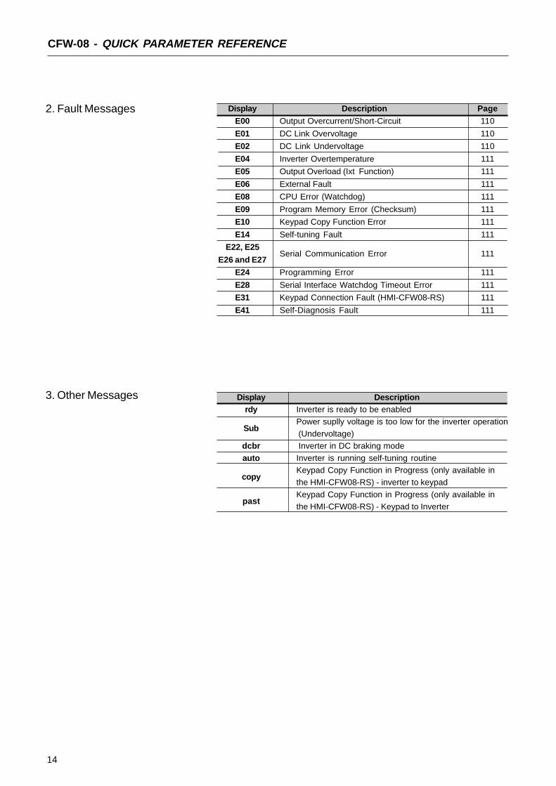
CFW-08 - QUICK PARAMETER REFERENCE
Display Description PageE00 Output Overcurrent/Short-Circuit 110
E01 DC Link Overvoltage 110
E02 DC Link Undervoltage 110
E04 Inverter Overtemperature 111
E05 Output Overload (Ixt Function) 111
E06 External Fault 111
E08 CPU Error (Watchdog) 111
E09 Program Memory Error (Checksum) 111
E10 Keypad Copy Function Error 111
E14 Self-tuning Fault 111
E22, E25Serial Communication Error 111
E26 and E27
E24 Programming Error 111
E28 Serial Interface Watchdog Timeout Error 111
E31 Keypad Connection Fault (HMI-CFW08-RS) 111
E41 Self-Diagnosis Fault 111
2. Fault Messages
3. Other Messages Display Descriptionrdy Inverter is ready to be enabled
SubPower suplly voltage is too low for the inverter operation
(Undervoltage)dcbr Inverter in DC braking mode
auto Inverter is running self-tuning routine
copyKeypad Copy Function in Progress (only available inthe HMI-CFW08-RS) - inverter to keypad
pastKeypad Copy Function in Progress (only available inthe HMI-CFW08-RS) - Keypad to Inverter
15
CHAPTER 1
SAFETY NOTICES
This Manual contains necessary information for the correct use of theCFW-8 Variable Frequency Drive.This Manual has been written for qualified personnel with suitable trainingand technical qualification to operate this type of equipment.
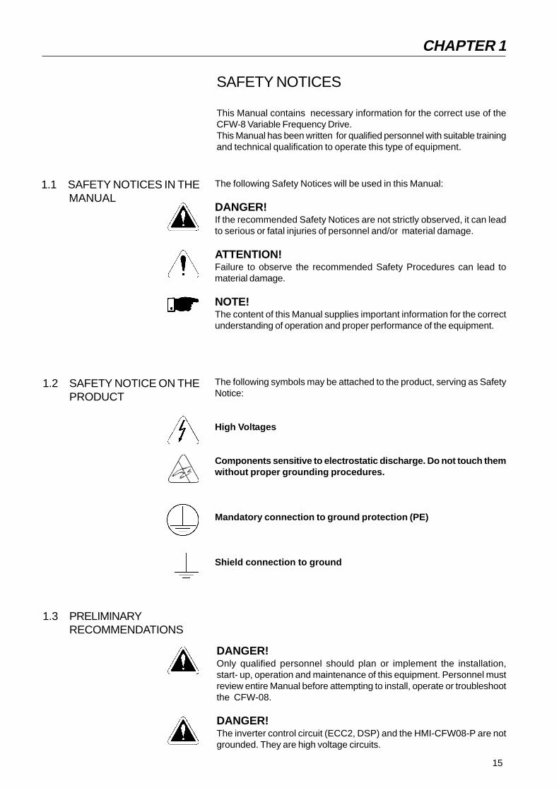
The following Safety Notices will be used in this Manual:
DANGER!If the recommended Safety Notices are not strictly observed, it can leadto serious or fatal injuries of personnel and/or material damage.
ATTENTION!Failure to observe the recommended Safety Procedures can lead tomaterial damage.
NOTE!The content of this Manual supplies important information for the correctunderstanding of operation and proper performance of the equipment.
The following symbols may be attached to the product, serving as SafetyNotice:
High Voltages
Components sensitive to electrostatic discharge. Do not touch themwithout proper grounding procedures.
Mandatory connection to ground protection (PE)
Shield connection to ground
DANGER!Only qualified personnel should plan or implement the installation,start- up, operation and maintenance of this equipment. Personnel mustreview entire Manual before attempting to install, operate or troubleshootthe CFW-08.
DANGER!The inverter control circuit (ECC2, DSP) and the HMI-CFW08-P are notgrounded. They are high voltage circuits.
1.3 PRELIMINARYRECOMMENDATIONS
1.2 SAFETY NOTICE ON THEPRODUCT
1.1 SAFETY NOTICES IN THE MANUAL

16
SAFETY NOTICES
These personnel must follow all safety instructions included in this Manualand/or defined by local regulations.Failure to comply with these instructions may result in personnel injury and/orequipment damage.
NOTE!In this Manual, qualified personnel are defined as people that are trained to:1. Install, ground, power up and operate the CFW-08 according to this
Manual and the local required safety procedures;2. Use of safety equipment according to the local regulations;3. Administer Cardio Pulmonary Resuscitation (CPR) and First Aid.
DANGER!Always disconnect the supply voltage before touching any electrical componentinside the inverter.
Many components are charged with high voltages, even after the incoming ACpower supply has been disconnected or switched OFF. Wait at least 10minutes for the total discharge of the power capacitors.
Always connect the frame of the equipment to the ground (PE) at the suitableconnection point.
ATTENTION!All electronic boards have components that are sensitive to electrostaticdischarges. Never touch any of the electrical components or connectors withoutfollowing proper grounding procedures. If necessary to do so, touch the properlygrounded metallic frame or use a suitable ground strap.
NOTE!Inverters can interfere with other electronic equipment. In order to reduce thisinterference, adopt the measures recommended in Section 3 “Installation”.
NOTE!Read this entire Manual carefully and completely before installing or operatingthe CFW-08.
Do not apply High Voltage (High Pot) Test on the Inverter!If this test is necessary, contact the Manufacturer.
This chapter defines the contents and purposes of this manual anddescribes the main characteristics of the CFW-08 frequency inverter.Identification, receiving inspections and storage requirements are alsoprovided.
This Manual is divided into 10 Chapter, providing infornation to the user onhow receive, install, start-up and operate the CFW-08:
Chapter 1 - Safety Notices;Chapter 2 - General Information;Chapter 3 - Installation;Chapter 4 - Start-up;Chapter 5 - Keypad HMI) Operation;Chapter 6 - Detailed Parameter Description;Chapter 7 - Diagnostic and Troubleshooting;Chapter 8 - CFW-08 Options and Accessories;Chapter 9 - Technical Specifications;Chapter 10 - Warranty Policy.
This Manual provides information for the correct use of the CFW-08. TheCFW-08 is very flexible and allows for the operation in many differentmodes as described in this manual.
As the CFW-08 can be applied in several ways, it is impossible to describehere all of the application possibilities. WEG does not accept anyresponsibility when the CFW-08 is not used according to this Manual.
No part of this Manual may be reproduced in any form, without the writtenpermission of WEG.
It is important to note the Software Version installed in the Version CFW-08, since it defines the functions and the programming parameters of theinverter.This Manual refers to the Software version indicated on the inside cover.For example, the Version 3.0X applies to versions 3.00 to 3.09, where “X”is a variable that will change due to minor software revisions. The operationof the CFW-08 with these software revisions are still covered by this versionof the Manual.
The Software Version can be read in the Parameter P023.
GENERAL INFORMATION
2.1 ABOUT THIS MANUAL
2.2 SOFTWARE VERSION
CHAPTER 2
18
GENERAL INFORMATION
2.3 ABOUT THE CFW-08 The CFW-08 is a high performance Variable Frequency Drive that permitsthe control of speed and torque of a three-phase AC induction motor. Twotypes of control are available in the same product:
Programmable scalar (Volts/Hz) control;
Sensorless Vector Control (VVC: Voltage Vector Control).
In the vector control mode, the motor performance is optimized relating totorque and speed regulation.The "Self-Tuning" function, available in vector control, permits the automaticsetting of the inverter parameter from the identification (also automatic) ofthe parameters of the motor connected at the inverter output.The V/F (scalar) mode is recommended for more simple applicationssuch as pump and fan drives. In these cases one can reduce the motorand inverter losses by using the "Quadratic V/F" option, that results inenergy saving.The V/F mode is also used when more than one motor should be drivensimultaneously by one inverter (multimotor application).
There are two CFW-08 versions:
Standard: it has 4 digital inputs (DIs), 1 analog input (AI) and 1 relayoutput.CFW-08 Plus: compared to the standard version it has one additionalanalog input and one additional relay output. It has also an analogoutput (AO).
For power ratings and further technical information, see Chaper 9.

19
GENERAL INFORMATION
Figure 2.1 - Block diagram for the models:1.6-2.6-4.0-7.0A/200-240V and 1.0-1.6-2.6-4.0A/380-480V
PowerSupply
RST
P E
PC-SoftwareSuperDrive
or
RS-485
MIW-02
AnalogInputs
(AI1 andAI2)
DigitalInputs
(DI1 to DI4)
POWERCONTROL
POWER SUPPLIES ANDCONTROL / POWER INTERFACES
"ECC2"CONTROL BOARD
WITH DSP
AnalogOutput(AO)
RelayOutput
(RL1 andRL2)
MotorUVW
Rsh2
Rsh1
NTC
PERFI Filter
InterfaceRS-232 KCS-CFW08
InterfaceMIS-CFW08-RS
HMI-CFW08-P
InterfaceMIP-CFW08-RP
or
or
or
HMI-CFW08-RS
HMI-CFW08-RP
20
GENERAL INFORMATION
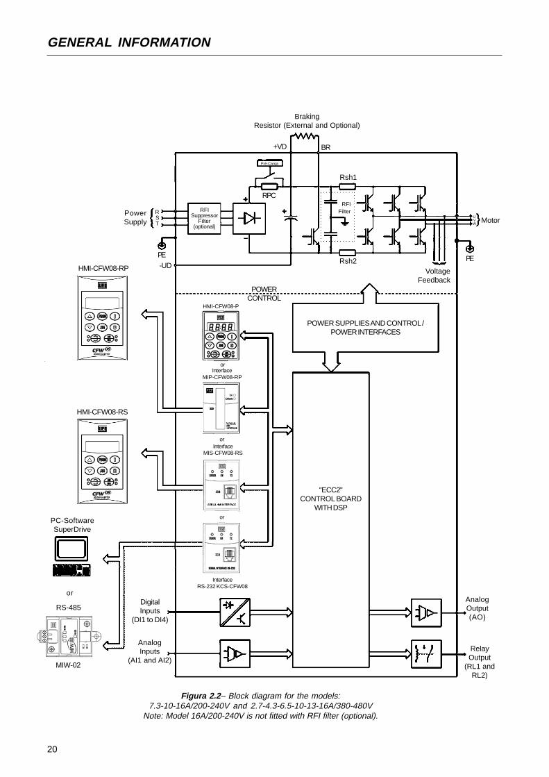
Figura 2.2– Block diagram for the models:7.3-10-16A/200-240V and 2.7-4.3-6.5-10-13-16A/380-480V
Note: Model 16A/200-240V is not fitted with RFI filter (optional).
PowerSupply
RST
RFISuppressor
Filter(optional)
PC-SoftwareSuperDrive
or
RS-485
MIW-02
AnalogInputs
(AI1 and AI2)
DigitalInputs
(DI1 to DI4)
POWERCONTROL
POWER SUPPLIES AND CONTROL /POWER INTERFACES
"ECC2"CONTROL BOARD
WITH DSP
AnalogOutput(AO)
RelayOutput
(RL1 andRL2)
MotorUVW
Rsh2
Rsh1
RPC
Pré-Carga
BrakingResistor (External and Optional)
BR+VD
PE-UD
VoltageFeedback
PE
RFIFilter
HMI-CFW08-RS
HMI-CFW08-RP
InterfaceRS-232 KCS-CFW08
InterfaceMIS-CFW08-RS
HMI-CFW08-P
InterfaceMIP-CFW08-RP
or
or
or
21
GENERAL INFORMATION
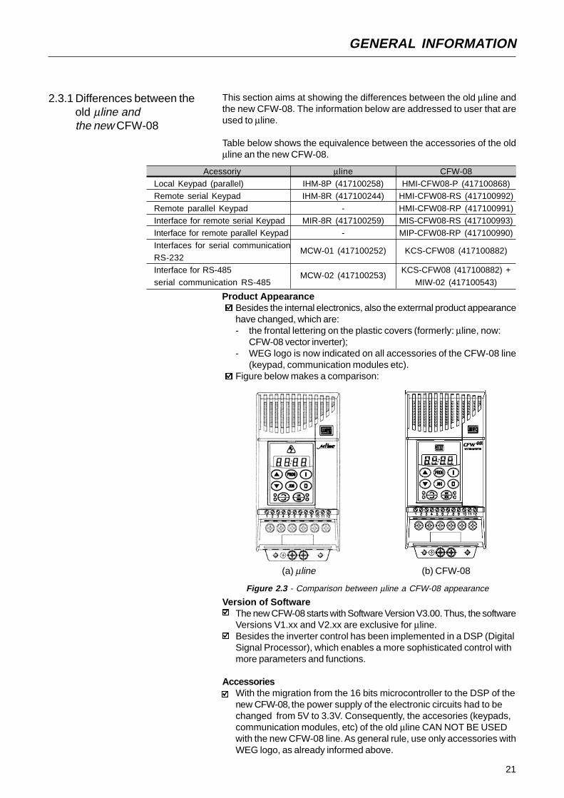
Product AppearanceBesides the internal electronics, also the exterrnal product appearancehave changed, which are:- the frontal lettering on the plastic covers (formerly: µline, now:
CFW-08 vector inverter);- WEG logo is now indicated on all accessories of the CFW-08 line
(keypad, communication modules etc).Figure below makes a comparison:
2.3.1 Differences between theold µline andthe new CFW-08
(a) µline (b) CFW-08
Figure 2.3 - Comparison between µline a CFW-08 appearance
Version of SoftwareThe new CFW-08 starts with Software Version V3.00. Thus, the softwareVersions V1.xx and V2.xx are exclusive for µline.Besides the inverter control has been implemented in a DSP (DigitalSignal Processor), which enables a more sophisticated control withmore parameters and functions.
AccessoriesWith the migration from the 16 bits microcontroller to the DSP of thenew CFW-08, the power supply of the electronic circuits had to bechanged from 5V to 3.3V. Consequently, the accesories (keypads,communication modules, etc) of the old µline CAN NOT BE USEDwith the new CFW-08 line. As general rule, use only accessories withWEG logo, as already informed above.
This section aims at showing the differences between the old µline andthe new CFW-08. The information below are addressed to user that areused to µline.
Table below shows the equivalence between the accessories of the oldµline an the new CFW-08.
AcessoriyLocal Keypad (parallel)Remote serial Keypad
Remote parallel KeypadInterface for remote serial KeypadInterface for remote parallel Keypad
Interfaces for serial communicationRS-232Interface for RS-485
serial communication RS-485
µlineIHM-8P (417100258)IHM-8R (417100244)
-MIR-8R (417100259)
-
MCW-01 (417100252)
MCW-02 (417100253)
CFW-08HMI-CFW08-P (417100868)
HMI-CFW08-RS (417100992)
HMI-CFW08-RP (417100991)MIS-CFW08-RS (417100993)MIP-CFW08-RP (417100990)
KCS-CFW08 (417100882)
KCS-CFW08 (417100882) +
MIW-02 (417100543)

22
GENERAL INFORMATION
Expansion of the Power RangeThe power range of the old µline (0.25-2HP) has been expanded to(0.25-10HP) with the new CFW-08 line.
Control ModesOnly the CFW-08 line has:- Voltage Vector Control (VVC) that improves the inverter performance considerably - adding the parameters P178, P399, P400, P402, P403, P404, P407, P408 e P409;- the quadratic curve V/F improves the systema energy saving capability when loads with quadratic torque x speed characteristics are driven, like pumps and fans.
Frequency ResolutionThe new CFW-08 has a frequency resolution 10 times higher than theold µline, i.e., it has a resoltion of 0.01Hz for frequencies up to 100.0Hzand of 0.1Hz for frequencies higher than 99.99Hz.
Switching Frequencies of 10 and 15kHzWhen the new CFW-08 is used, one can set the inverter switchingfrequency to 10 and 15kHz, which enables an extremly quiet operation.The audible noise level generated by the motor with 10 kHz is lowerwith the CFW-08, when compared with the µline. This is due to thePWM modulation improvements of the CFW-08.
Inputs and Outputs (I/Os)The CFW-08 Plus line has more I/Os than the old µline, while theCFW-08 is equivalent to the µline in terms of of I/Os. See table below:
I/ODigital InputsAnalog Input(s)
Analog Outputs
Relay Outputs
µline41-
1(REV contatct)
CFW-0841
-1
(REV contact)
CFW-08 Plus42
12 (1 NO contact,1 NC contact)
23
GENERAL INFORMATION
I/O
Digital Input DI1Digital Input DI2Digital Input DI3
Digital Input DI40V for Digital Inputs+10V
Analog Input AI1 -voltage signalAnalog Input AI1 -
current signal0V for analoginput(s)
Analog Input AI2 -voltage signalAnalog Input AI2 -
current signal
Saída Analógica AO
Relay Ouput RL1
Relay Output RL2
µline1
234
56
7
9
8
not
availablenot
available
notavailablel
10(NF), 11(C)
and 12(NA)not
available
CFW-08
123
456
7 with switchS1:1 at pos. OFF
7 with switch
S1:1 at pos. ON
5
notavailable
not
availablenot
available
10(NF), 11(C)and 12(NA)
not
available
CFW-08 Plus
123
456
7 with switch S1:1at position OFF
7 with switch S1:1
at position ON
5
8 with switch S1:2at position OFF
8 with switch S1:2
at position ON
9
11-12(NO)
10-11(NC)
Parameters and Functions
Parameters that are already used in µµµµµline but have been changeda) P136 - Manual Torque Boost (IxR Compensation)
Besides the parameter name, also the way the user enters the IxRcompensation value has been changed. In the old µline, theparameter P136 had a family of 10 curves (value range: 0 to9). In the new CFW-08, the IxR Compensation is set by entering apercent (relating to the input voltage) that defines the output voltagefor an output frequency equal to zero. So larger curve set and alarger variation range is obtained.
Table below shows the equivalence between which was programmedin the old µline and which must be programmed in the new CFW-08 to obtain the same result.
P136 set in µline0
123
456
789
P136 to be set in the CFW-080.0
2.55.07.5
10.012.515.0
17.520.022.5
But the control connections (terminals XC1) differ between the µlineand the CFW-08 line. Table below shows theses pin differences:

24
GENERAL INFORMATION
b) Automatic Torque Boost (Automatic IxR Compensation) and SlipCompensation
In the µline only the rated motor current (P401) was used inthe Automatic IxR Compensation and the Slip Compensationfunctions. In the µline the rated motor power factor of the motorwas considered as a fixed value and equal to 0.9.Now in the new CFW-08, are used the parameters P401 and P407(rated motor power factor). Thus:
Example: When in an application with the µline the following settingwas required: P401=3.8A, now with the new CFW-08 you must performthe following setting: P401=3.8A and P407=0.9orP407= rated cos ∅ of the used motor and P401=3.8 x 0.9
P407
Parameters existing only in Special Software Versions of the µµµµµlinea) Quick Inputs
In the new CFW-08, the response time of the the digital inputs is10ms (max.).In addition, the minimum acceleration and deceleration time wasreduced from 0.2s (µline) to 0.1s (CFW-08). Besides the DC brakingprocess can be interrupted before it has been concluded, forinstance, when a new enabling is required.
b) Other changesP120=2 - digital reference backup via P121 independently of thereference source.P265=14 - DI3: multispeed using ramp #2.
New Parameters and FunctionsThe reference 1 of the multispeed that was in Parameter P121 (inµline) is now in Parameter P124 (in CFW-08).The DC link regulation level (ramp holding) can now beprogrammed in Parameter P151 - in the µline this level was fixed to377V for the 200-240V line and 747V for the 380-480V line.Also the programming way of Parameter P302 has changed. In theµline P302 was related to the voltage applied to the output during theDCbraking, now in the new CFW-08, P302 defines the DC BrakingCurrent.PID regulator.Suammarizing, the new parameters are: P009, P040, P124, P151,P178, P202, P203, P205, P219, P238, P239, P240, P251, P252, P279,P399, P400, P402, P403, P404, P407, P408, P409, P520, P521, P522,P525, P526, P527 e P528.
P401 uline
. 0.9 = P401 x P407 CFW-08

25
GENERAL INFORMATION
2.4 CFW-08 IDENTIFICATION
Figure 2.4 - Description and location of the nameplates
SoftwareVersion
HardwareRevision
Rated Input Data(Voltage, Number ofPhases Current,Frequency)
Manufacturing DateWEG Part NumberSerial Number
CFW-08 Model
Rated Output Data(Voltage, Frequency)
Lateral Nameplate of the CFW-08
Frontal Nameplate of the CFW-08 (under the keypad)
Note: To remove thekeypad, see instructionsin 8.1.1 (Figure 8.2).
WEG Part Number
Seriel Number
CFW-08-Model
Manufacturing DateHardware Revision
Software Version

26
GENERAL INFORMATION
CF
W-0
800
40B
2024
PO
0000
0000
0000
Z
Rat
ed O
utpu
tC
urre
nt f
or
200
to 2
40V
:00
16=
1.6A
0026
=2.
6A00
40=
4.0A
0070
=7.
0A00
73=
7.3A
0100
=10
A01
60=
16A
380
to 4
80V
:00
10=
1.0A
0016
=1.
6A00
26=
2.6A
0027
=2.
7A00
40=
4.0A
0043
=4.
3A00
65=
6.5A
0100
=10
A01
30=
13A
0160
=16
A
Num
ber
ofph
ases
of
the
pow
ersu
pply
:S
=si
ngle
phas
eT
=th
ree
phas
eB
=si
ngle
phas
e or
thre
e ph
ase
Man
ual
Lang
uage
:P
= P
ortu
g.E
= E
nglis
hS
= S
pani
shF
= F
renc
hG
= G
erm
an
Po
we
rS
uppl
y:20
24 =
200
to 2
40V
3848
=38
0 to
480
V
Opt
ions
:S
= s
tand
ard
O=
with
optii
ons
Deg
ree
ofP
rote
ctio
n:B
lank
=st
anda
rdN
1= N
ema
1
Hum
anM
achi
neIn
terf
ace:
blan
kst
anda
rdS
I= w
ithou
tin
terf
ace
(with
dum
my
pane
l)
WE
GS
erie
s 08
Fre
quen
cyIn
vert
er
Con
trol
Boa
rd:
Bla
nk =
stan
dard
cont
rol
A1=
con
trol 1
(Plu
s V
ersi
on)
Spe
cial
So
ftw
are
:00
= n
one
End
Cod
eR
FI F
ilter
:B
lank
=w
itho
ut
filte
rFA
=C
lass
AR
FI f
ilte
r(in
tern
al o
rfo
otpr
int)
Spe
cial
Ha
rdw
are
:00
= n
one
HO
W T
O S
PE
CIF
Y T
HE
CF
W-0
8 M
OD
EL:
27
GENERAL INFORMATION
2.5 Receiving andStoring
NOTE!The Option field (S or O) defines if the CFW-08 is a standard version orif it will be equipped with any optional devices. If the standard versionis required, the specification code ends here.The model number has always the letter Z at the end. For example:
CFW080040S2024ESZ = standard 4.0A CFW-08 inverter, single-phaseat 200...240V input with manual in English.
For the effect of this code, the standard product is conceived as follows:- CFW-08 with standard control board.- Degree of protection: NEMA 1 for the models 13 and 16A/380-480V;
IP20 for the other models.
If the CFW-08 is equipped with any optional devices, you must fill outall fields in the correct sequence up to the last optional device, themodel number is completed with the letter Z. It is not necessary toindicate the code number 00 for those optional devices that are standardor that will not be used.
Thus, for instance if the product above is required with NEMA 1 degreeof protection:CFW080040S2024EON1Z = CFW-08 inverter, 4A, single-phase,200...240V input, with manual in English language and with kitf forNEMA 1 degree of protection.
The CFW-08 Plus is formed by the inverter and the control board 1.Example: CFW080040S2024EOA1Z.
7.0 and 16.0A/200-240V and for all 380-480V models are just availablewith three-phase power supply.
A RFI Class A filter (optional) can be installed inside the inverter inmodels 7.3 and 10A/200-240V (single-phase) and 2.7, 4.3, 6.5, 10, 13and 16A/380-480V. Models 1.6, 2.6 and 4.0A/200-240V (single-phase)and 1.0, 1.6, 2.6 and 4.0A/380-480V can be provided mounted on afootprint RFI Class A filter (optional).
The listing of the existing models (voltage/current) is shown in item 9.1.
The CFW-08 is supplied in cardboard boxes.The outside of the packing box has a nameplate that is identical to thaton the CFW-08.Please check if the CFW-08 is the one you ordered.Check if the:
CFW-08 nameplate data matches with your purchase order.The equipment has not been damaged during transport.If any problem is detected, contact the carrier immedately.
If the CFW-08 is not installed immediately, store it in a clean and dryroom (storage temperatures between –25°C and 60°C). Cover it toprotect it against dust, dirt or other contamination.

28
CHAPTER 3
INSTALLATION
3.1 MECHANICAL INSTALLATION
This chapter describes the procedures for the electrical and mechanicalinstallation of the CFW-08.These guidelines and suggestions must be followed for proper CFW-08operation.
3.1.1 Environment The location of the inverter installation is an important factor to assuregood performance and high product reliability. For proper installation, wemake the following recommendations:
Avoid direct exposure to sunlight, rain, high moisture and sea air.Avoid exposure to gases or explosive or corrosive liquids;Avoid exposure to excessive vibration, dust, oil or any conductiveparticles or materials.
Environmental Conditions:Temperature : 32...104ºF (0 ... 40ºC) - nominal conditions. 32...122ºF(0 ... 50ºC) - with 2% current derating for each 1.8ºF (1ºC) degreeabove 104ºF (40ºC).Relative Air Humidity: 5% to 90% - non-condensing.Maximum Altitude: 3,300 ft (1000m) - nominal conditions.3,300...13,200 ft (1000 ... 4000m) - with 10% current reduction foreach 3,300 ft (1000m) above 3,300 ft (1000m).Pollution Degree: 2 (according to EN50178 and UL508C)
NOTE!When inverters are installed in panels or in closed metallic boxes, adequatecooling is required to ensure that the temperature arounds the inverter willnot exceed the maximim allowed temperature. See Dissipated Power inSection 9.1.

29
INSTALLATION AND CONNECTION
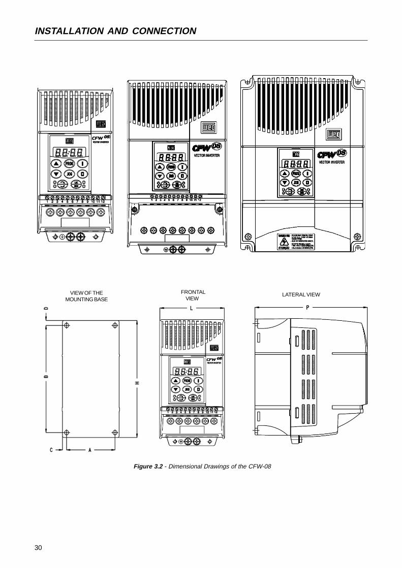
Table 3.1 - Recommended free spaces
Install the inverter in vertical position.Leave free space around the inverter as indicated in Table 3.1.Do not install heat sensitive components immediately above theinverter.When inverters are installed side by side, maintain the minimumrecommended distance B.When inverters are installed top and bottom, maintain the minimumrecommended distance A + C and deflect the hot air coming fromthe inverter below.Install the inverter on a flat surface.External dimensions and mounting holes are according to Fig. 3.2.For CFW-08 installation procedures, see Fig. 3.3.Provide independent conduits for signal, control and powerconductors. (Refer to Electrical Installation). Separate the motorcables from the other cables.
CFW-08 Model1.6A / 200-240V
2.6A / 200-240V4.0A / 200-240V7.0A / 200-240V
1.0A / 380-480V1.6A / 380-480V2.6A / 380-480V
4.0A / 380-480V7.3A / 200-240V10.0A / 200-240V
16.0A / 200-240V2.7A / 380-480V4.3A / 380-480V
6.5A / 380-480V10.0A / 380-480V13.0A / 380-480V
16.0A / 380-480V
A B C D
30 mm 1.18 in 5 mm 0.20 in 50 mm 2 in 50 mm 2 in
35 mm 1.38 in 15 mm 0.59 in 50 mm 2 in 50 mm 2 in
40 mm 1.57 in 30 mm 1.18 in 50 mm 2 in 50 mm 2 in
3.1.2 Mounting Specification
Figure 3.1 - Free Space for Cooling
30
INSTALLATION AND CONNECTION
Figure 3.2 - Dimensional Drawings of the CFW-08
VIEW OF THEMOUNTING BASE
FRONTALVIEW
LATERAL VIEW
31
INSTALLATION AND CONNECTION
Inverter
Model
1.6A / 200-240V
2.6A / 200-240V
4.0A / 200-240V
7.0A / 200-240V
7.3A / 200-240V
10A / 200-240V
16A / 200-240V
1.0A / 380-480V
1.6A / 380-480V
2.6A / 380-480V
2.7A / 380-480V
4.0A / 380-480V
4.3A / 380-480V
6.5A / 380-480V
10A / 380-480V
13A / 380-480V
16A / 380-480V
Width L
in(mm)2.95
(75)2.95(75)
2.95(75)2.95
(75)4.53(115)
4.53(115)4.53
(115)2.95(75)
2.95(75)2.95
(75)4.53(115)
2.95(75)4.53
(115)4.53(115)
4.53(115)5.63
(143)5.63(143)
Height Hin
(mm)
5.95(151)5.95
(151)5.95(151)
5.95(151)7.87
(200)7.87(200)
7.87(200)5.95
(151)5.95(151)
5.95(151)7.87(200)
5.95(151)7.87
(200)7.87(200)
7.87(200)7.99
(203)7.99(203)
Depth P
in(mm)5.16
(131)5.16(131)
5.16(131)5.16
(131)5.91(150)
5.91(150)5.91
(150)5.16(131)
5.16(131)5.16
(131)5.91(150)
5.16(131)5.91
(150)5.91(150)
5.91(150)6.50
(165)6.50(165)
A in
(mm)
2.52(64)2.52
(64)2.52(64)
2.52(64)3.98
(101)3.98(101)
3.98(101)2.52
(64)2.52(64)
2.52(64)3.98
(101)2.52(64)
3.98(101)3.98
(101)3.98(101)
4.76(121)4.76
(121)
Bin
(mm)
5.08(129)5.08
(129)5.08(129)
5.08(129)6.97
(177)6.97(177)
6.97(177)5.08
(129)5.08(129)
5.08(129)6.97
(177)5.08(129)
6.97(177)6.97
(177)6.97(177)
7.09(180)7.09
(180)
Cin
(mm)
0.20(5)
0.20
(5)0.20(5)
0.20(5)
0.28
(7)0.28(7)
0.28(7)
0.20
(5)0.20(5)
0.20(5)
0.28
(7)0.20(5)
0.28(7)
0.28
(7)0.28(7)
0.43(11)0.43
(11)
Din
(mm)
0.24(6)
0.24
(6)0.24(6)
0.24(6)
0.20
(5)0.20(5)
0.20(5)
0.24
(6)0.24(6)
0.24(6)
0.20
(5)0.24(6)
0.20(5)
0.20
(5)0.20(5)
0.39(10)0.39
(10)
MountingScrew
5/32(M4)
5/32(M4)5/32
(M4)5/32(M4)
5/32(M4)5/32
(M4)5/32(M4)
5/32(M4)5/32
(M4)5/32(M4)
5/32(M4)5/32
(M4)5/32(M4)
5/32(M4)5/32
(M4)3/16(M5)
3/16(M5)
Weigth lb
(kg)
2.2(1.0)2.2
(1.0)2.2
(1.0)
2.2(1.0)4.4
(2.0)4.4
(2.0)
4.4(2.0)2.2
(1.0)2.2
(1.0)
2.2(1.0)4.4
(2.0)2.2
(1.0)
4.4(2.0)4.4
(2.0)4.4
(2.0)
5.5(2.5)5.5
(2.5)
Degree of
Protection
IP20 / NEMA1
IP20 / NEMA1
IP20 / NEMA1
IP20 / NEMA1
IP20 / NEMA1
IP20 / NEMA1
IP20 / NEMA1
IP20 / NEMA1
IP20 / NEMA1
IP20 / NEMA1
IP20 / NEMA1
IP20 / NEMA1
IP20 / NEMA1
IP20 / NEMA1
IP20 / NEMA1
NEMA1
NEMA1
Dimensions Fixing base
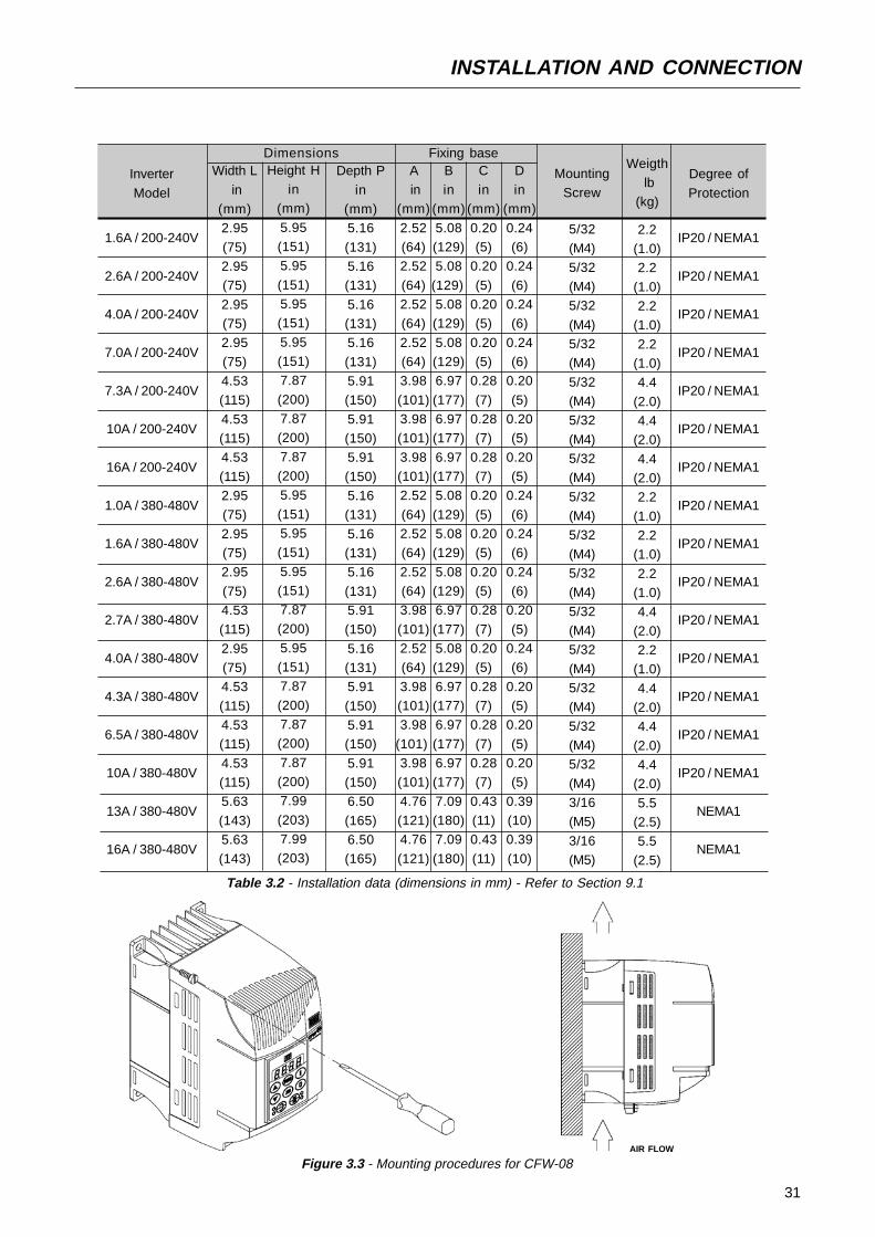
Table 3.2 - Installation data (dimensions in mm) - Refer to Section 9.1
Figure 3.3 - Mounting procedures for CFW-08AIR FLOW

32
INSTALLATION AND CONNECTION
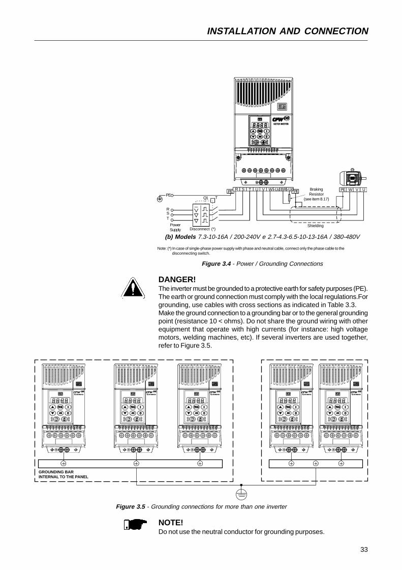
(a) Models 1.6-2.6-4.0-7.0A / 200-240V and 1.0-1.6-2.6-4.0A / 380-480V
PE
RST
PowerSupply Disconnect (*)
PE
TQ1
R S T U V W PE PE W V U
DANGER!AC input disconnection: provide and AC input disconnecting switch toswitch OFF the input power to the inverter.This device shall disconnect the inverter from the AC input supply whenrequired (e.g. during maintenances services).
DANGER!This AC input disconnecting switch can not be used as an emergencystop device.
DANGER!Be sure that the AC input power is disconnected before making any ter-minal connection.
DANGER!The information below will be a guide to achieve a proper installation.Followalso all applicable local standards for electrical installations.
ATENTION!Provide at least 10 in (0.25m) spacing between the equipment and sensitivewirings and betwen the cables of the inverter and motor. For instance:PLCs, temperature monitoring devices, thermocouples, etc.
3.2 ELECTRICAL INSTALLATION
3.2.1 Power / GroundingConnections
33
INSTALLATION AND CONNECTION
NOTE!Do not use the neutral conductor for grounding purposes.
Figure 3.5 - Grounding connections for more than one inverter
GROUNDING BARINTERNAL TO THE PANEL
DANGER!The inverter must be grounded to a protective earth for safety purposes (PE).The earth or ground connection must comply with the local regulations.Forgrounding, use cables with cross sections as indicated in Table 3.3.Make the ground connection to a grounding bar or to the general groundingpoint (resistance 10 < ohms). Do not share the ground wiring with otherequipment that operate with high currents (for instance: high voltagemotors, welding machines, etc). If several inverters are used together,refer to Figure 3.5.
Figure 3.4 - Power / Grounding Connections
(b) Models 7.3-10-16A / 200-240V e 2.7-4.3-6.5-10-13-16A / 380-480V
Note: (*) In case of single-phase power supply with phase and neutral cable, connect only the phase cable to the disconnecting switch.
PE
RST
PowerSupply
PE
TQ1
R S T U V W PE
Shielding
PE W V U-Ud BR+Ud BrakingResistor
(see item 8.17)
Disconnect (*)
34
INSTALLATION AND CONNECTION
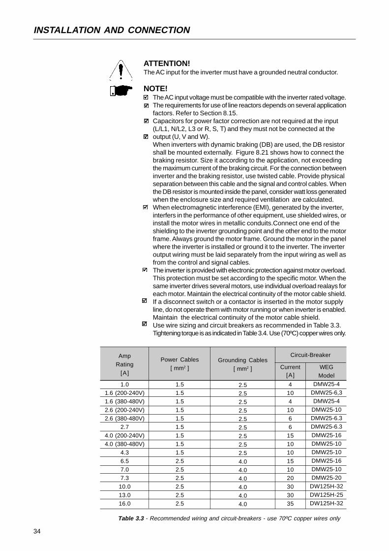
Table 3.3 - Recommended wiring and circuit-breakers - use 70ºC copper wires only
AmpRating
[ A ]
1.01.6 (200-240V)1.6 (380-480V)
2.6 (200-240V)2.6 (380-480V)
2.7
4.0 (200-240V)4.0 (380-480V)
4.3
6.57.07.3
10.013.016.0
Power Cables[ mm2 ]
1.51.51.5
1.51.51.5
1.51.51.5
2.52.52.5
2.52.52.5
Grounding Cables
[ mm2 ]
2.52.52.5
2.52.52.5
2.52.52.5
4.04.04.0
4.04.04.0
Current[ A ]
4104
1066
151010
151020
303035
WEGModel
DMW25-4DMW25-6,3DMW25-4
DMW25-10DMW25-6.3DMW25-6.3
DMW25-16DMW25-10DMW25-10
DMW25-16DMW25-10DMW25-20
DW125H-32DW125H-25DW125H-32
Circuit-Breaker
ATTENTION!The AC input for the inverter must have a grounded neutral conductor.
NOTE!The AC input voltage must be compatible with the inverter rated voltage.The requirements for use of line reactors depends on several applicationfactors. Refer to Section 8.15.Capacitors for power factor correction are not required at the input(L/L1, N/L2, L3 or R, S, T) and they must not be connected at theoutput (U, V and W).When inverters with dynamic braking (DB) are used, the DB resistorshall be mounted externally. Figure 8.21 shows how to connect thebraking resistor. Size it according to the application, not exceedingthe maximum current of the braking circuit. For the connection betweeninverter and the braking resistor, use twisted cable. Provide physicalseparation between this cable and the signal and control cables. Whenthe DB resistor is mounted inside the panel, consider watt loss generatedwhen the enclosure size and required ventilation are calculated.When electromagnetic interference (EMI), generated by the inverter,interfers in the performance of other equipment, use shielded wires, orinstall the motor wires in metallic conduits.Connect one end of theshielding to the inverter grounding point and the other end to the motorframe. Always ground the motor frame. Ground the motor in the panelwhere the inverter is installed or ground it to the inverter. The inverteroutput wiring must be laid separately from the input wiring as well asfrom the control and signal cables.The inverter is provided with electronic protection against motor overload.This protection must be set according to the specific motor. When thesame inverter drives several motors, use individual overload realays foreach motor. Maintain the electrical continuity of the motor cable shield.If a disconnect switch or a contactor is inserted in the motor supplyline, do not operate them with motor running or when inverter is enabled.Maintain the electrical continuity of the motor cable shield.Use wire sizing and circuit breakers as recommended in Table 3.3.Tightening torque is as indicated in Table 3.4. Use (70ºC) copper wires only.
35
INSTALLATION AND CONNECTION
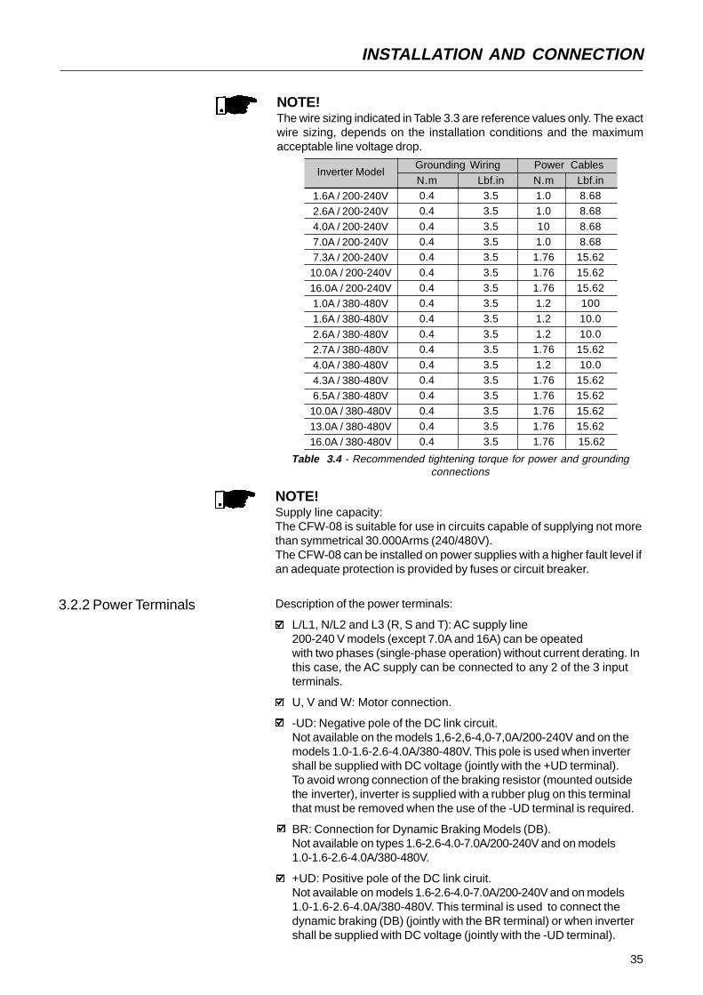
NOTE!Supply line capacity:The CFW-08 is suitable for use in circuits capable of supplying not morethan symmetrical 30.000Arms (240/480V).The CFW-08 can be installed on power supplies with a higher fault level ifan adequate protection is provided by fuses or circuit breaker.
3.2.2 Power Terminals Description of the power terminals:
L/L1, N/L2 and L3 (R, S and T): AC supply line200-240 V models (except 7.0A and 16A) can be opeatedwith two phases (single-phase operation) without current derating. Inthis case, the AC supply can be connected to any 2 of the 3 inputterminals.
U, V and W: Motor connection.
-UD: Negative pole of the DC link circuit.Not available on the models 1,6-2,6-4,0-7,0A/200-240V and on themodels 1.0-1.6-2.6-4.0A/380-480V. This pole is used when invertershall be supplied with DC voltage (jointly with the +UD terminal).To avoid wrong connection of the braking resistor (mounted outsidethe inverter), inverter is supplied with a rubber plug on this terminalthat must be removed when the use of the -UD terminal is required.
BR: Connection for Dynamic Braking Models (DB).Not available on types 1.6-2.6-4.0-7.0A/200-240V and on models1.0-1.6-2.6-4.0A/380-480V.
+UD: Positive pole of the DC link ciruit.Not available on models 1.6-2.6-4.0-7.0A/200-240V and on models1.0-1.6-2.6-4.0A/380-480V. This terminal is used to connect thedynamic braking (DB) (jointly with the BR terminal) or when invertershall be supplied with DC voltage (jointly with the -UD terminal).
NOTE!The wire sizing indicated in Table 3.3 are reference values only. The exactwire sizing, depends on the installation conditions and the maximumacceptable line voltage drop.
Inverter Model
1.6A / 200-240V2.6A / 200-240V4.0A / 200-240V
7.0A / 200-240V7.3A / 200-240V
10.0A / 200-240V
16.0A / 200-240V1.0A / 380-480V1.6A / 380-480V
2.6A / 380-480V2.7A / 380-480V4.0A / 380-480V
4.3A / 380-480V6.5A / 380-480V
10.0A / 380-480V
13.0A / 380-480V16.0A / 380-480V
Grounding Wiring
N.m Lbf.in0.4 3.50.4 3.5
0.4 3.50.4 3.50.4 3.5
0.4 3.50.4 3.50.4 3.5
0.4 3.50.4 3.50.4 3.5
0.4 3.50.4 3.50.4 3.5
0.4 3.50.4 3.50.4 3.5
Power Cables
N.m Lbf.in1.0 8.681.0 8.68
10 8.681.0 8.68
1.76 15.62
1.76 15.621.76 15.621.2 100
1.2 10.01.2 10.0
1.76 15.62
1.2 10.01.76 15.621.76 15.62
1.76 15.621.76 15.621.76 15.62
Table 3.4 - Recommended tightening torque for power and groundingconnections

36
INSTALLATION AND CONNECTION
3.2.3 Location of the Power,Grounding and ControlConnections
(a) Models 1.6-2.6-4.0-7.0-7.3-10-16A/200-240V and 1.0-1.6-26-2.7-40-4.3-65-10A/380-480V
Control (XC1)
Power
Grounding
(b) models 7.3-10-16A/200-240V and 2.7-4.3-6.5-10A/380-480V
U V W -Ud BR +Ud
(a) models 1.6-2.6-4.0-7.0A/200-240V and 1.0-1.6-2.6-4.0A/380-480V
L3 U V WL/L1
Figure 3.6 - Power terminals
(c) models 13-16A/380-480V
N/L2
L3L/L1 N/L2
37
INSTALLATION AND CONNECTION
3.2.4 Control Wiring
The control wiring (analog inputs/outputs, digital inputs and relay outputsis made on the XC1 connector of control board (see location in Figure 3.7,Section 3.2.3).There are two configurations for the control board: standard version(CFW-08 line) and Plus version (CFW-08 Plus line), as shown below:
Figure 3.8 - XC1 control terminal description (standard control board - CFW-08)Note: NC = Normally Closed Contact, NO = Normally Open Contact
Figure 3.7 - Location of the power/grounding and control connections
(b) Models 13-16A/380-480V
Control XC1
Power
Grounding
XC1 Terminal
1 DI1
2 DI2
3 DI3
4 DI4
5 GND
6 AI1
7 +10V
8
9
10 NC
11 Commom
12 NO
DescriptionFactory Default Function
Digital Input 1General Enable (remote mode)Digital Input 2
FWD / REV (remote mode)Digital Input 3Reset
Digital Input 4Start / Stop (remote mode)
0V Reference
Analog Input 1
Frequency / Speed Reference(remote mode)
Potentiometer reference
Not used
Not usedRelay Output 1 - NC contact
No Fault
Relay Output 1 - common point
Relay Output 1 - NO contact
No Fault
Specifications
4 isolated digital inputs
Minimum High Level: 10VDCMaximum Low Level: 3VDCInput current: -11mA @ 0V
Max. input current: -20 mA
Not connected to PE
0 to 10VDC or 0(4) to 20mA (fig. 3.10).Impedance: 100kΩ (0...10V input),
500Ω (0/4...20mA input).Resolution: 7bits.Max. input voltage: 30 VDC
+10VDC ± 5%, capacity: 2mA
Contact capacity:0.5A / 250VAC
Relé 1
CW
CCW
≥5k
Ω
10 12
11

38
INSTALLATION AND CONNECTION
Figure 3.9 - XC1 control terminal description of the control board 1 (CFW-08 Plus)
Figure 3.10 - Dip switch position for 0 ...10V/4 ... 20mA selection
S1
21
OFF ON
Conector XC1
1 DI1
2 DI2
3 DI3
4 DI4
5 GND
6 AI1
7 +10V
8 AI2
9 AO
10 NF
11 Comum
12 NA
Description
Factory Default Function
Digital Input 1
General Enable (remote mode)
Digital Input 2
FWD / REV (remote mode)
Digital Input 3
Reset
Digital Input 4
Start/Stop (remote mode)
0V Reference
Analog input 1
Frequency/Speed reference (remote mode)
Potentiometer reference
Analog input 2
Not used
Analog output
Output Frequency (Fs)
Relay Output 2 - NC contact
Fs>Fx
Relay outputs common points
Relay Output 1 - NO contact
No Fault
Specifications
4 isolated digital inputs
Minimum High Level: 10VDC
Maximum Low Level: 3VDC
Input Current: -11mA @ 0V
Max. Input Current: -20 mA
Not connected to PE
0 to 10VDC or 0(4) to 20mA (fig. 3.10).
Impedance: 100kΩ (0...10V input), 500Ω(0/4...20mA input).
Resolution: 7bits.
Max. input voltage: 30VDC
+10VDC, ± 5%, capacity: 2mA
0 to 10VDC or 0(4) to 20mA (fig. 3.10).
Impedance: 100kΩ (0...10V input), 500Ω
(0/4...20mA input).
Resolution: 7bits.
Max. input voltage: 30Vdc
0 to 10VDC, RL ≥ 10k ΩResolution: 8bits
Contact capacity:
0.5A / 250VAC
CW
CCW
≥ 10k
Ω
RPM
-
+
Relé 1
11
Relé 2
12 10
CCW
CW
≥ 10k
Ω
39
INSTALLATION AND CONNECTION
Analog Input
AI1
AI2
Factory Deafult Setting
Frequency / Speed
Reference (remote mode)
No function
DipSwitch S1.1
S1.2
Selection
OFF: 0 ... 10V
ON: 4 ... 20mA or 0 ... 20mAOFF: 0 ... 10VON: 4 ... 20mA or 0 ... 20mA
Table 3.5 - Dip switch configuration
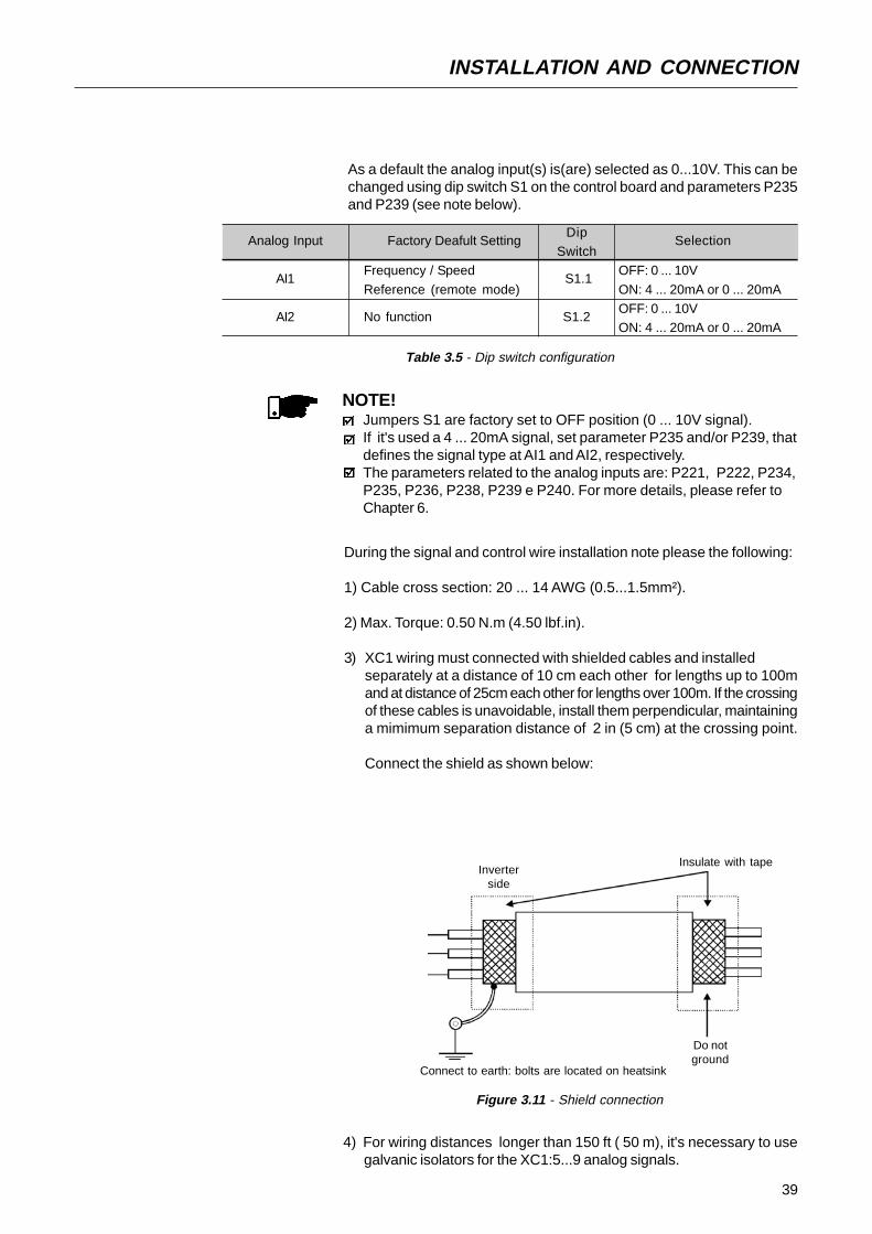
NOTE!Jumpers S1 are factory set to OFF position (0 ... 10V signal).If it's used a 4 ... 20mA signal, set parameter P235 and/or P239, thatdefines the signal type at AI1 and AI2, respectively.The parameters related to the analog inputs are: P221, P222, P234,P235, P236, P238, P239 e P240. For more details, please refer toChapter 6.
During the signal and control wire installation note please the following:
1) Cable cross section: 20 ... 14 AWG (0.5...1.5mm²).
2) Max. Torque: 0.50 N.m (4.50 lbf.in).
3) XC1 wiring must connected with shielded cables and installedseparately at a distance of 10 cm each other for lengths up to 100mand at distance of 25cm each other for lengths over 100m. If the crossingof these cables is unavoidable, install them perpendicular, maintaininga mimimum separation distance of 2 in (5 cm) at the crossing point.
Connect the shield as shown below:
Figure 3.11 - Shield connection
Connect to earth: bolts are located on heatsink
Do notground
Inverterside
Insulate with tape
4) For wiring distances longer than 150 ft ( 50 m), it's necessary to usegalvanic isolators for the XC1:5...9 analog signals.
As a default the analog input(s) is(are) selected as 0...10V. This can bechanged using dip switch S1 on the control board and parameters P235and P239 (see note below).

40
INSTALLATION AND CONNECTION
5) Relays, contactors, solenoids or eletromagnetic braking coils installednear inverters can generate interferences in the control circuit. Toeliminate this interference, connect RC suppressor in parallel with thecoils of AC relays. Connect free-wheeling diode in case of DC relays.
6) When external keypad (HMI) is used (refer to Chapter 8), separetethe cable that connects the keypad to the inverter from other cables,maintaining a minimum distance of 4 in (10 cm) between them.
7) When analog reference (AI1 or AI2) is used and the frequencyoscillates (problem caused by eletromagnetic interference)connect XC1:5 to the inverter heatsink.
3.2.5 Typical TerminalConnections
Connection 1 - Keypad Start/Stop (Local Mode)
With the factory default programming, you can operate the inverter inlocal mode with the minimum connections shown in Figure 3.4 (Power)and without control connections. This operation mode is recommendedfor users who are operating the inverter for the first time. Note that there isno need of connection of control terminals.
For start-up according to this operation mode, refer to Chapter 4.
Connection 2 - 2-Wire Start/Stop (Remote Mode)
Valid for factory default programming and inverter operating in remotemode. For the factory default programming, the selection of the operationmode (local/remote) is made via the key (default is local).
S1: FWD / REV
S2: Reset
S3: Start / Stop
R1: Potentiometer for speed setting
Figure 3.12 - XC1 wiring for connection 2
No
Fun
ctio
n or
Gen
eral
Ena
blin
g
1 2 3 4 5 6 7 8 9 10 11 12
DI2
- F
WD
/ R
EV
DI3
- R
eset
CO
M
AI1
+10V
AI2
AO
1
NC
Com
mon
NO
DI4
- N
o F
unct
ion
or S
tart
/Sto
p
R1
S3S2S1
5k≥
41
INSTALLATION AND CONNECTION
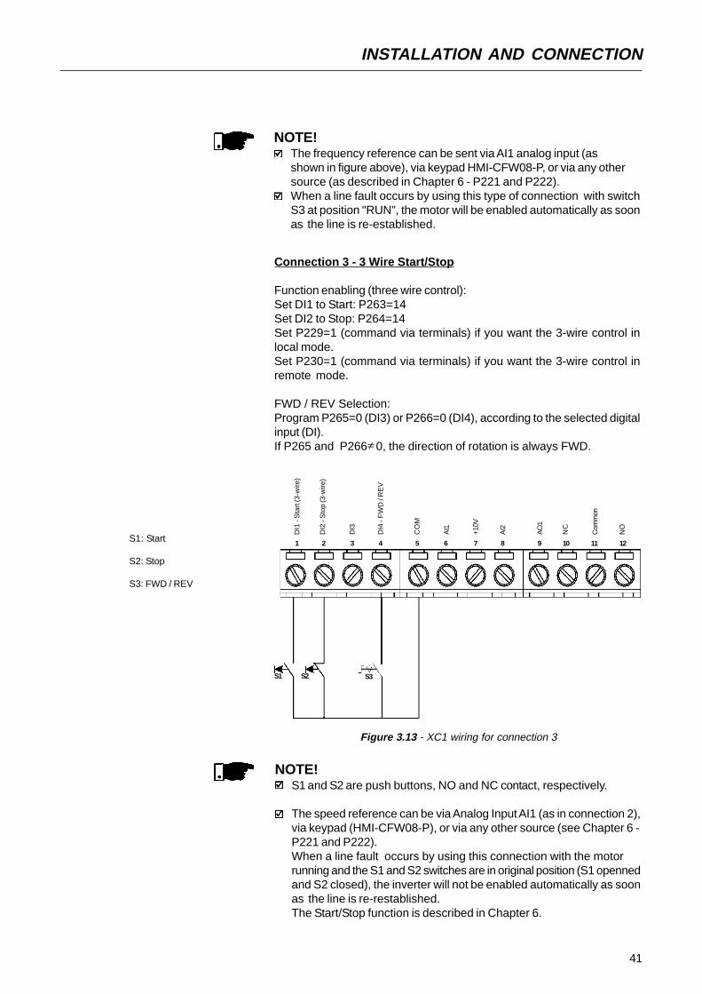
Connection 3 - 3 Wire Start/Stop
Function enabling (three wire control):Set DI1 to Start: P263=14Set DI2 to Stop: P264=14Set P229=1 (command via terminals) if you want the 3-wire control inlocal mode.Set P230=1 (command via terminals) if you want the 3-wire control inremote mode.
FWD / REV Selection:Program P265=0 (DI3) or P266=0 (DI4), according to the selected digitalinput (DI).If P265 and P266 0, the direction of rotation is always FWD.≠
Figure 3.13 - XC1 wiring for connection 3
NOTE!The frequency reference can be sent via AI1 analog input (asshown in figure above), via keypad HMI-CFW08-P, or via any othersource (as described in Chapter 6 - P221 and P222).When a line fault occurs by using this type of connection with switchS3 at position "RUN", the motor will be enabled automatically as soonas the line is re-established.
NOTE!S1 and S2 are push buttons, NO and NC contact, respectively.
The speed reference can be via Analog Input AI1 (as in connection 2),via keypad (HMI-CFW08-P), or via any other source (see Chapter 6 -P221 and P222).When a line fault occurs by using this connection with the motorrunning and the S1 and S2 switches are in original position (S1 opennedand S2 closed), the inverter will not be enabled automatically as soonas the line is re-restablished.The Start/Stop function is described in Chapter 6.
S1: Start
S2: Stop
S3: FWD / REV
DI1
- S
tart
(3-w
ire)
DI2
- S
top
(3-w
ire)
DI3
CO
M
AI1
+10V
AI2
AO
1
NC
Com
mon
NO
DI4
- F
WD
/ R
EV
S3S2S1
1 2 3 4 5 6 7 8 9 10 11 12

42
INSTALLATION AND CONNECTION
Connection 4 - FWD RUN / REV RUN
Parameter to be programmed:Set DI1 to Forward Run : P263 = 8Set DI2 to Reverse Run: P264 = 8Make sure the inverter commands are via terminals, i.e., P229=1 to localmode or P230=1 to remote mode.
Figure 3.14 - XC1 wiring for connection 4
S1 open: StopS1 closed: Forward Run
S2 open: StopS2 closed: Reverse Run
NOTE!The speed reference can be via Analog Input AI1 (as in connection 2),via keypad (HMI-CFW08-P), or via any other source (see descriptionof parameters P221 and P222 in Chapter 6).When a line fault occurs, this connection with switch S1 orswitch S2 is closed, the motor will be enabled automatically as soonas the line is re-restablished.
DI1
- F
orw
ard
Run
DI2
- R
ever
se R
un
DI3
CO
M
AI1
+10V
AI2
AO
1
NC
Com
mon
NO
DI4
- N
o F
unct
ion/
Gen
eral
Ena
blin
g
S2S1
1 2 3 4 5 6 7 8 9 10 11 12

43
INSTALLATION AND CONNECTION
3.3 European EMC Directive -Requirements forConforming Installations
The CFW-08 inverter series was designed considering safety and EMC(ElectroMagnetic Compatibility) aspects.The CFW-08 units do not have an intrinsic function until connected withother components (e. g. a motor). Therefore, the basic product is not CEmarked for compliance with the EMC Directive. The end user takes personalresponsibility for the EMC compliance of the whole installation. However,when installed according to the recommendations described in the productmanual and including the recommended filters and EMC measures theCFW-08 fulfill all requirements of the EMC Directive (89/336/EEC) asdefined by the EMC Product Standard for Adjustable Speed ElectricalPower Drive Systems EN61800-3.Compliance of the CFW-08 series is based on the testing of therepresentative models. A Technical Construction File was checked andapproved by a Competent Body.
3.3.1 Installation Figure 3.15 below shows the EMC filters connection.
Figure 3.15 - EMC filters connection - general condition
The following items are required in order to have a conforming installation:1) The motor cable must be armored, flexible armored or installed inside a
metallic conduit or trunking with equivalent attenuation. Ground the screen/metallic conduit at both ends (inverter and motor).
2) Control (I/O) and signal wiring must be shielded or installed inside ametallic conduit or trunking with equivalent attenuation.
3) The inverter and the external filter must be mounted on a common metallicback plate with a positive electrical bond and in close proximity to oneanother. Ensure that a good electrical connection is made between theheatsink (inverter) / frame (external filter) and the back plate.
4) The length of the wiring between filter and inverter must be kept as shortas possible.
5) The cable’s shielding must be solidly connected to the common backplate, using a metal bracket.
6) Grounding as recommended in this manual.7) Use short and thick earthing cable to earth the external filter or inverter.
When an external filter is used, only use an earth cable at filter input -the inverter earth connection is done by the metallic back plate.
8) Earth the back plate using a braid, as short as possible. Flat conductors(e.g. braids or brackets) have lower impedance at high frequencies.
9) Use cable glands whenever possible.
Output CMChokeTransformer
Ground Rod/Grid orBuilding SteelStructure
Metallic Cabinet (when required)
Protective Grounding - PE
Motor
PE
CFW - 08
L2/N
L1/L
L3
E
PE
XC1 1...12
U
Input CMChoke
Controling and Signal Wiring
V
W
PE
L1/L
L2/N
L3
ExternalInput RFI
Filter
L2
L1
L3
E
Obs.: Single-phase input inverters use single-phase filters and only L1/L and L2/N are used.

44
INSTALLATION AND CONNECTION
3.3.2 Inverter Models and Filters Table 3.6 below shows the inverter models and the respective RFI filterand the EMC category number. A description of each EMC category isgiven in item 3.3.3. The characteristics of the footprint and external inputRFI filters are given in item 3.3.4.
Id Inverter Model
1 CFW080016S2024...FAZ2 CFW080026S2024...FAZ3 CFW080040S2024...FAZ
4CFW080016B2024...FAZ(single-phase input)
5CFW080026B2024...FAZ
(single-phase input)
6CFW080040B2024...FAZ(single-phase input)
7CFW080073B2024...FAZ(single-phase input)
8CFW080100B2024...FAZ
(single-phase input)9 CFW080016S2024...
10 CFW080026S2024...
11 CFW080040S2024...
12CFW080016B2024...(single-phase input)
13CFW080026B2024...(single-phase input)
14CFW080040B2024...
(single-phase input)
15CFW080016B2024...(three-phase input)
16CFW080026B2024...(three -phase input)
17CFW080040B2024...
(three -phase input)
18 CFW080070T2024...
19CFW080073B2024...(single-phase input)
20CFW080073B2024...
(three-phase input)
21 CFW080100B2024...(single-phase input)
22CFW080100B2024...(three-phase input)
23 CFW080160T2024...
24 CFW080010T3848...FAZ25 CFW080016T3848...FAZ
26 CFW080026T3848...FAZ27 CFW080040T3848...FAZ28 CFW080027T3848...FAZ
29 CFW080043T3848...FAZ30 CFW080065T3848...FAZ31 CFW080100T3848...FAZ
32 CFW080130T3848...FAZ33 CFW080160T3848...FAZ
Input RFI Filter
Built-in filter[ FEX1-CFW08(footprint filter) ]
Built-in filter
FS6007-16-06(external filter)
FS3258-7-45(external filter)
FN3258-16-45(external filter)
FS6007-25-08(external filter)FN3258-16-45
(external filter)FS6007-36-08(external filter)
FN3258-16-45(external filter)FN3258-30-47
(external filter)
Built-in filter[ FEX2-CFW08
(footprint filter) ]
Built-in filter
EMC Category
Category I (industrial)
Category II (domestic)
Category I (industrial)
Dimensions(Width x Height x Depth)
79x190x182mm
115x200x150mm
Inverter: 75x151x131mmFilter: 85.5x119x57.6mm
Inverter: 75x151x131mmFilter: 40x190x70mm
Inverter: 75x151x131mmFilter: 45x250x70mm
Inverter: 115x200x150mmFilter: 85.5x119x57.6mm
Inverter: 115x200x150mm
Filter: 45x250x70mmInverter: 115x200x150mmFilter: 85.5x119x57.6mm
Inverter: 115x200x150mmFilter: 45x250x70mm
Inverter: 115x200x150mm
Filter: 50x270x85mm
79x190x182mm
115x235x150mm
143x203x165mm
45
INSTALLATION AND CONNECTION
Obs.:1) Category II systems must be mounted inside a metallic cabinet in
order to have radiated emissions below the limits for first environmentand restricted distribution (see item 3.3.3). Category I systems do notrequire a metallic cabinet. Exception: models 7 and 8, that need to bemounted inside a cabinet to pass in the radiated emission test forsecond environment and unrestricted distribution (see item 3.3.3). Whena metallic cabinet is required, the maximum length of the remote keypadcable is 3m. In this case, the control (I/O) and signal wiring must belocated inside the cabinet and the remote keypad can be installed inthe cabinet front door (see items 8.3.1 and 8.5).
2) The maximum switching frequency is 10kHz. Exception: 5kHz formodels 24 up to 33 (category I, 380-480V models). For category Isystems see also note 7.
3) The maximum motor cable length is 20m for models 9, 10, 11, 12, 13,14, 15, 16, 17, 18, 19, 20, 21, 22, 23, 34, 35, 36 and 37, 10m formodels 1, 2, 3, 4, 5, 6, 7, 8, 24, 25, 26, 27, 38, 39, 40, 41, 42 and 43and 5m for models 28, 29, 30, 31, 32 and 33. For category I systemssee also note 7.
4) In models 28, 29, 30 and 31 (see also note 7), a CM choke at inverteroutput is required: TOR1-CFW08, 1 turn. The toroid is mounted insidethe N1 kit that is provided with these models. For installation see figure3.15.
5) In models 38, 39, 40, 41, 42 and 43, a CM choke at filter input isrequired: TOR2-CFW08, 3 turns. For installation see figure 3.15.
6) In models 38, 39, 40 and 41, it is required to use a shielded cablebetween the external filter and the inverter.
7) Category I systems were also tested using second environmentunrestricted distribution limits for conducted emissions (for definitionssee notes 2 and 3 of item 3.3.3). In this case:- the maximum cable length is 30m for models 1, 2, 3, 4, 5, 6, 7, 8,
32 and 33 and 20m for models 24, 25, 26, 27, 28, 29, 30 and 31;- the maximum switching frequency is 10kHz for models 28, 29, 30
and 31 and 5kHz for models 1, 2, 3, 4, 5, 6, 7, 8, 24, 25, 26, 27, 32and 33;
- models 28, 29, 30 and 31 do not require any CM choke at inverteroutput (as stated in note 4).
Id Inverter Model
34 CFW080010T3848...35 CFW080016T3848...36 CFW080026T3848...
37 CFW080040T3848...38 CFW080027T3848...39 CFW080043T3848...
40 CFW080065T3848...41 CFW080100T3848...
42 CFW080130T3848...
43 CFW080160T3848...
Input RFI Filter
FN3258-7-45(external filter)
FN3258-16-45(external filter)
FN3258-30-47(external filter)
EMC Category
Category II (domestic)
Dimensions(Width x Height x Depth)
Inverter: 75x151x131mmFilter: 40x190x70mm
Inverter: 115x200x150mmFilter: 40x190x70mm
Inverter: 115x200x150mmFilter: 45x250x70mm
Inverter: 143x203x165mm
Filter: 45x250x70mmInverter: 143x203x165mm
Filter: 50x270x85mm
Table 3.6 - Inverter models list with filters and EMC category

46
INSTALLATION AND CONNECTION
EMC phenomenon
Emission:Conducted emissions (mains terminal
disturbance voltage - freq band 150kHzto 30MHz)Radiated emissions (electromagnetic
radiation disturbance - freq band 30MHzto 1000MHz)Immunity:Electrostatic discharge (ESD)
Fast transient-burst
Conducted radio-frequencycommon mode
Surge
Radio-frequency electromagnetic field
Basic standardfor test method
IEC/EN61800-3
IEC/EN61800-3
IEC 61000-4-2
IEC 61000-4-4
IEC 61000-4-6
IEC 61000-4-5
IEC 61000-4-3
Level
First environment (*1), unrestricted distribution (*3) -Class B
First environment (*1), restricted distribution (*4,5)
6kV contact discharge
4kV/2.5kHz (capacitive clamp) input cable; 2kV/5kHz controlcables; 2kV/5kHz (capacitive clamp) motor cable; 1kV/5kHz(capacitive clamp) external keypad cable
0.15 to 80MHz; 10V;80% AM (1kHz) - motor control and remote Keypad cable1.2/50µs, 8/20µs;
1kV coupling line to line;2kV coupling line to earth80 to 1000MHz; 10V/m; 80% AM (1kHz)
Category II
3.3.3 EMC CategoriesDescription
There are two EMC categories: Category I for industrial applications andCategory II for residential applications, as described below.
EMC phenomenon
Emission:Conducted emissions (mains terminaldisturbance voltage - freq band 150kHz
to 30MHz)Radiated emissions (electromagneticradiation disturbance - freq band 30MHz
to 1000MHz)Immunity:Electrostatic discharge (ESD)
Fast transient-burst
Conducted radio-frequencycommon mode
Surge
Radio-frequency electromagnetic field
Basic standard
for test method
IEC/EN61800-3
IEC/EN61800-3
IEC 61000-4-2
IEC 61000-4-4
IEC 61000-4-6
IEC 61000-4-5
IEC 61000-4-3
Level
First environment (*1), restricted distribution (*4,5) - Class A
Second environment (*2), unrestricted distribution (*3)
6kV contact discharge4kV/2.5kHz (capacitive clamp) input cable; 2kV/5kHz control
cables; 2kV/5kHz (capacitive clamp) motor cable; 1kV/5kHz(capacitive clamp) external keypad cable0.15 to 80MHz; 10V;
80% AM (1kHz) - motor control and remote Keypad cable1.2/50µs, 8/20µs;1kV coupling line to line;
2kV coupling line to earth80 to 1000MHz; 10V/m; 80% AM (1kHz)
Category I

47
INSTALLATION AND CONNECTION
3.3.4 EMC FiltersCharacteristics Filter
Table 3.7 - EMC filters characteristics
Filter WEG P/N Rated current WeightDimensions
Drawings(Width x Height x Depth)
FEX1-CFW08 417118238 10A0.6kg 79x190x51mm Fig. 3.16
FEX2-CFW08 417118239 5A
FS6007-16-06 0208.2072 16A 0.9kg 85.5x119x57.6mm Fig. 3.17FS6007-25-08 0208.2073 25A 1.0kg
85.5x119x57.6mm Fig. 3.18FS6007-36-08 0208.2074 36A 1.0kg
FN3258-7-45 0208.2075 7A 0.5kg 40x190x70mmFig. 3.19FN3258-16-45 0208.2076 16A 0.8kg 45x250x70mm
FN3258-30-47 0208.2077 30A 1.2kg 50x270x85mm
TOR1-CFW08 417100895 - 80gφe=35mm,
Fig. 3.20h=22mm
TOR2-CFW08 417100896 - 125gφe=52mm,
Fig. 3.21h=22mm
Obs.:1) First environment: environment that includes domestic premises. It
also includes establishments directly connected without intermediatetransformers to a low-voltage power supply network which suppliesbuildings used for domestic purposes.
2) Second environment: environment that includes all establishments otherthan those directly connected to a low-voltage power supply networkwhich supplies buildings used for domestic purposes.
3) Unrestricted distribution: mode of sales distribution in which the supplyof equipment is not dependent on the EMC competence of the customeror user for the application of drives.
4) Restricted distribution: mode of sales distribution in which themanufacturer restricts the supply of equipment to suppliers, customersor users who separately or jointly have technical competence in theEMC requirements of the application of drives.
(source: these definitions were extracted from the product standardIEC/EN61800-3 (1996) + A11 (2000))
5) This is a product of restricted sales distribution class according to theproduct standard IEC/EN61800-3 (1996) + A11 (2000). In a domesticenvironment this product may cause radio interference in which casethe user may be required to take adequate measures.
6) The harmonic current emissions defined by the standards IEC/EN61000-3-2 and EN61000-3-2 / A14 do not apply because the CFW-08 inverterseries are intended for professional applications.

48
INSTALLATION AND CONNECTION
Figure 3.17 - FS6007-16-06 external filter drawing
Figure 3.16 - FEX1-CFW08 and FEX2-CFW08 footprint filter drawing
Front View Lateral Right View
Bottom ViewTerminal block forflexible and rigid cableof 4mm2 or AWG 10.Max. torque: 0.8Nm
(a) Footprint Filter (b) Footprint Filter and Inverter
Bottom View
Front ViewLateral Right View
Type /05Fast-on terminal 6.3 x 0.8mm

49
INSTALLATION AND CONNECTION
Figure 3.19 - FS3258-xx-xx external filter drawing
Type/45Terminal block for 6mm2
solid cable,4mm2 flexible cable AWG 12.
Top ViewSide View
Connector
Rated Current
Type/47Terminal block for 16mm2
solid wires,10mm2 flexible wires AWG 8.
Mechanical Data
Front View
Figure 3.18 - FS6007-25-08 and FS6007-36-08 external filter drawing
Bolt type 08=M4
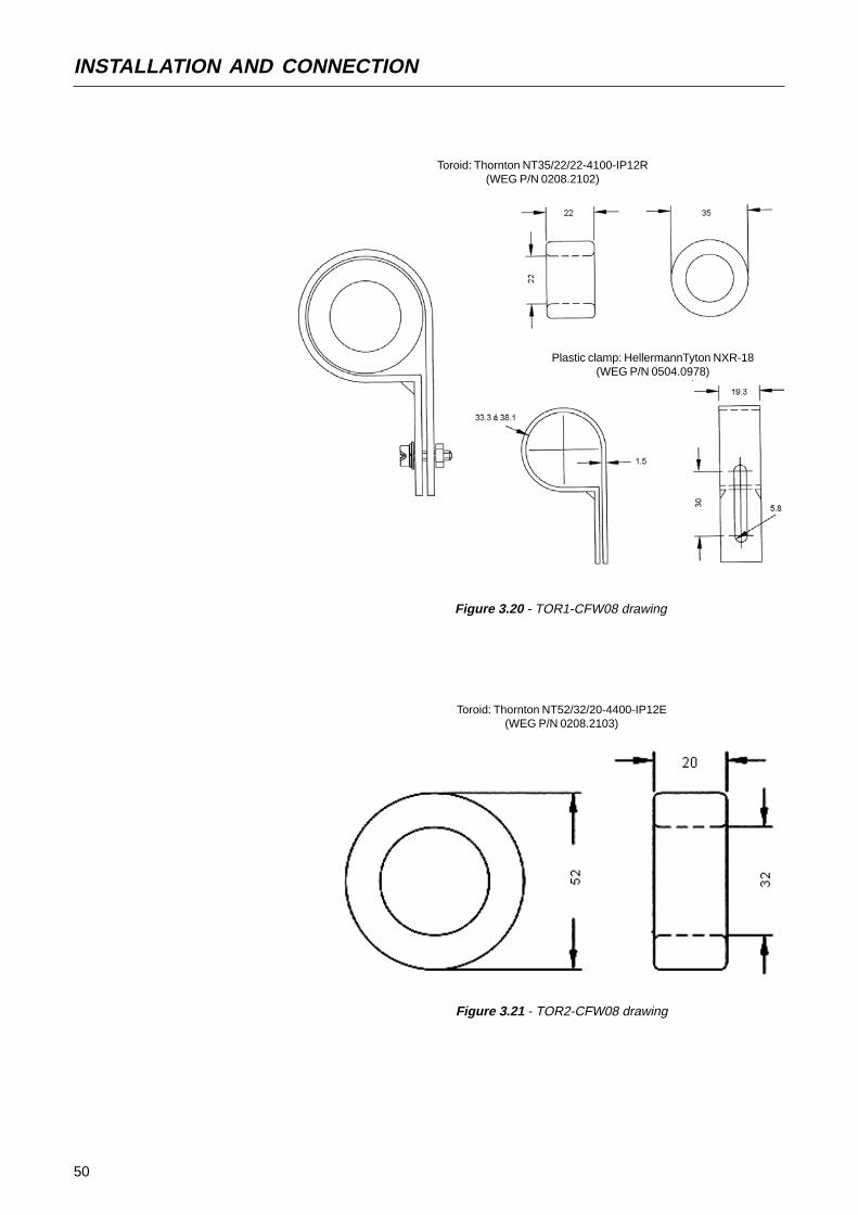
50
INSTALLATION AND CONNECTION
Toroid: Thornton NT35/22/22-4100-IP12R(WEG P/N 0208.2102)
Plastic clamp: HellermannTyton NXR-18(WEG P/N 0504.0978)
Figure 3.20 - TOR1-CFW08 drawing
Toroid: Thornton NT52/32/20-4400-IP12E(WEG P/N 0208.2103)
Figure 3.21 - TOR2-CFW08 drawing

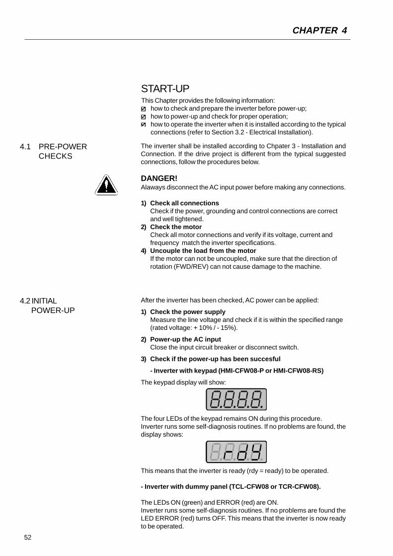
52
4.1 PRE-POWERCHECKS
This Chapter provides the following information:how to check and prepare the inverter before power-up;how to power-up and check for proper operation;how to operate the inverter when it is installed according to the typicalconnections (refer to Section 3.2 - Electrical Installation).
The inverter shall be installed according to Chpater 3 - Installation andConnection. If the drive project is different from the typical suggestedconnections, follow the procedures below.
DANGER!Alaways disconnect the AC input power before making any connections.
1) Check all connectionsCheck if the power, grounding and control connections are correctand well tightened.
2) Check the motorCheck all motor connections and verify if its voltage, current andfrequency match the inverter specifications.
4) Uncouple the load from the motorIf the motor can not be uncoupled, make sure that the direction ofrotation (FWD/REV) can not cause damage to the machine.
4.2 INITIAL POWER-UP
After the inverter has been checked, AC power can be applied:
1) Check the power supplyMeasure the line voltage and check if it is within the specified range(rated voltage: + 10% / - 15%).
2) Power-up the AC inputClose the input circuit breaker or disconnect switch.
3) Check if the power-up has been succesful
- Inverter with keypad (HMI-CFW08-P or HMI-CFW08-RS)
The keypad display will show:
The four LEDs of the keypad remains ON during this procedure.Inverter runs some self-diagnosis routines. If no problems are found, thedisplay shows:
This means that the inverter is ready (rdy = ready) to be operated.
- Inverter with dummy panel (TCL-CFW08 or TCR-CFW08).
The LEDs ON (green) and ERROR (red) are ON.Inverter runs some self-diagnosis routines. If no problems are found theLED ERROR (red) turns OFF. This means that the inverter is now readyto be operated.
START-UP
CHAPTER 4

53
START-UP
4.3 START-UP
4.3.1 Start-upOperation via Keypad(HMI)- Type of Control:Linear V/F(P202=0)
Connections according to Figure 3.4.
ACTION HMI DISPLAY DESCRIPTION
Power-up the inverter
Press the key
Press the key and hold itdepressed until 60 Hz is reached
Press the key
Press the key
Press the key and hold it
depressed
Inverter is ready to be operated
Motor accelerates from 0Hz to 3Hz*
(min. frequency), in the forward (CW) directionof rotation (1) * 90rpm for 4 pole motor.
Motor accelerates up to 60Hz* (2)
* 1800rpm for 4-pole motor
Motor decelerates (3) down to 0 rpm and
then reverses the direction of rotationCW⇒CWW accelerating back to 60Hz
Motor decelerates down to 0 rpm
Motor accelerates up to JOG frequencygiven by P122. Ex: P122 = 5.00Hz.Reverse (CCW)
DANGER!Even after the AC power supply has been disconnected, high voltagesmay be still present. Wait at least 10 minutes after powering down toallow full discharge of the capacitors.
The sequence below is valid for the connection 1 (refer to Section 3.2.5).Inverter must be already installed and powered up according to Chapter 3and Section 4.2.
This Section describes start-up procedures when operating via the keypad(HMI). Two types of control will be considered:V/F and Vetor ControlThe V/F control is recommended in the following cases:
several motors driven by the same inverter;rated current of the motor is lower than 1/3 of rated inverter currentfor test purposes, inverter is start-up without load.
The V/F control can also be used in applications that do not require fastdynamic responses, accurate speed regulations or high starting torque(speed error will be a function of the motor slip); when you programparameter P138 - rated slip - you can obtain a speed accuracy of 1%.For the most applications, we recommend the vector control mode, thatpermits a higher speed control accuracy (typical 0.5%), higher startingtorque and a faster dynamic response.
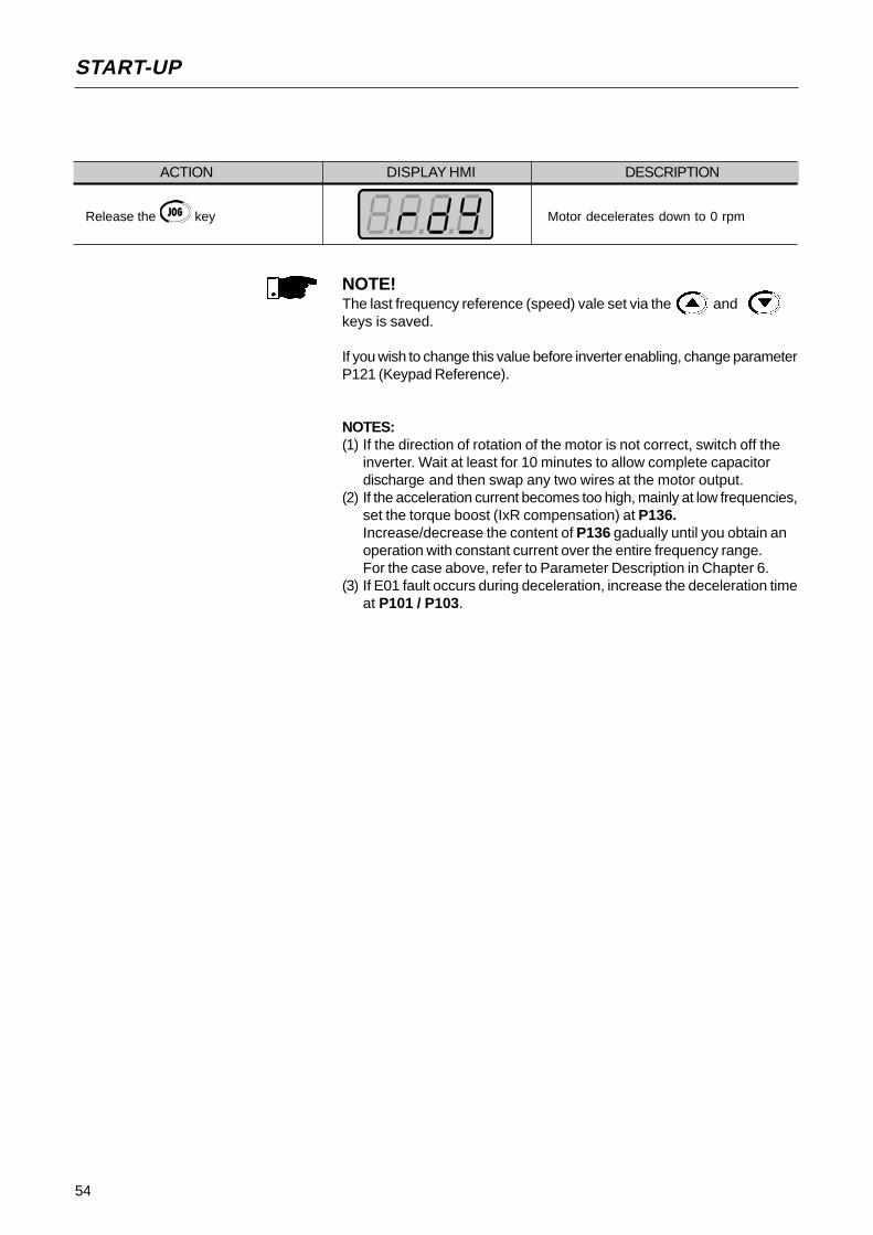
54
START-UP
NOTE!The last frequency reference (speed) vale set via the andkeys is saved.
If you wish to change this value before inverter enabling, change parameterP121 (Keypad Reference).
NOTES:(1) If the direction of rotation of the motor is not correct, switch off the
inverter. Wait at least for 10 minutes to allow complete capacitordischarge and then swap any two wires at the motor output.
(2) If the acceleration current becomes too high, mainly at low frequencies,set the torque boost (IxR compensation) at P136.Increase/decrease the content of P136 gadually until you obtain anoperation with constant current over the entire frequency range.For the case above, refer to Parameter Description in Chapter 6.
(3) If E01 fault occurs during deceleration, increase the deceleration timeat P101 / P103.
ACTION DISPLAY HMI DESCRIPTION
Release the key Motor decelerates down to 0 rpm

55
START-UP
4.3.2 Start-upOperation Via Terminals -Control Mode:Linear V/F (P202=0) Connections are according to Figures 3.4 and 3.12.
ACTION HMI DISPLAY DESCRIPTIONSee Figure 3.12Switch S1 (FWD / REV)=open
Switch S2 (Reset)=openSwitch S3 (Start/Stop)=openPotentiometer R1 (Ref.)=totalzly CCW
Power-up inverter
Press the key
This procedure is not necessary wheninverters were delivered dummy panel,
since it will be automatically in remotemode.
Close S3 – Start/Stop
Turn potentiometer totally CW.
Clse S1 – FWD / REV
Open S3 – Start / Stop
Inverter is ready to be operated.
Led LOCAL switches OFF and ledREMOTE switches ON. Control andReference are are switched to REMOTE
(via terminals).To maintain inverter permanently inREMOTE mode, set P220 = 1.
Note: If the inverter is switched off andafterwards switched on, it will nowoperate in local mode because P220=2
(factory setting). This setting means thatthe local/remote selection source is viakeypad and the default mode (that is the
mode when the inverter is switched on)is local. For further information seedescription of P220 in Chapter 6.
Motor accelerates from 0Hz to 3Hz* (min.frequency), CW direction (1)
* 90rpm for 4-pole motor
The frequency reference is given by thepotentiometer R1.
Motor accelerates up to the the maximumfrequency (P134 = 66Hz) (2)
Motor decelerates (3) down to 0 rpm (0Hz),reverses the direction of rotation (CW ⇒CWW) accelerating back up to themaximum frequency (P134 = 66Hz).
Motor decelerates (3) down to 0 rpm.
NOTES!(1) If the direction of roation of the motor rotation is not correct, switch off
the inverter. Wait 10 minutes to allow a complete capacitor dischargeand the swap any two wires at the motor output.
(2) If the acceleration current becomes too high, mainly at low frequencies,set the torque boost (IxR compensation) at P136.Increase/decrease the content of P136 gadually until you obtain anoperation with constant current over the entire frequency range.For the case above, refer to Parameter Description in Chapter 6.
(3) If E01 fault occurs during deceleration, increase the deceleration timeat P101 / P103.

56
START-UP
4.3.3 Start-upOperation via Keypad -Control Mode:Vector (P202=2)
The sequence below is based on the following inverter and motor example:Inveter: CFW080040S2024ESZMotor: WEG-IP55
Power: 0.75HP/0.55kW;Frame size: 71; RPM: 1720; Number of Poles: IV;Power factor (cos ϕ): 0.70;Efficiency (η): 71%;Rated Current at 220V: 2.90A;Frequency: 60Hz.
NOTE!The notes in Table below can be found on page 60.
ACTION HMI DISPLAY DESCRIPTION
Power-up inverter
Press . key. Press the keyuntil P000 is reached. You can also
use the key to reach theParamater P000.
Press the key to enter into the
programming mode.
Use the keys and toset the passowrd value.
Press the key to save theselected option and to exit the
programming mode.
Press the key or untilP202 is reached.
Press the key to enter into the
programming mode.
Use the and keys to
select the control type
Press the to save the selected
option and to start the tuning routineafter changing to Vector Control mode
Press the key and use the keyskeys and to set the
correct rated motor efficiency (in thiscase 71%)
Inverter is ready to be operated
P000=access for changing parameters
Enter the programming mode
P000=5: permits parameter changing
Exit the programming mode
This parameter defines the control type0=V/F Linear
1=V/F Quadratic2=Vector
Enter the programming mode
P202=2: Vector
Motor efficiency:50 ... 99,9%
Set motor efficiency:71%

57
START-UP
ACTION HMI DISPLAY DESCRIPTION
Press the key to save theselected option and to exit theprogramming mode
Press the key to go to the next
parameter
Press the key and use the keys
and to set the correctrated motor voltage
Press the key to save theselected option and exit the
programming mode
Press the key to go to the next
parameter
Press the key and use the keys
and o set the correct ratedmotor current (in this case 2.90A)
Press the key to save theselected option and to exit theprogramming mode
Press the to go to the nextparameter
Press the key and use the keys
and the to set the correctmotor speed (in this case 1720rpm)
Press the key to save theselected option and exit theprogramming mode
Press the key to go to the nextparameter
Press the and use the keys and to set the correct
value for the motor frequency.
Press the key to save theselected option and exit theprogramming mode
Exit the programming mode
Rated motor voltage range:0 ... 600V
Set rated motor voltage: 220V (the default value is maintained) (2)
Exit the programming mode
Rated motor current range:0.3 x Inom ... 1.3 x Inom
Set rated motor current: 2.90A
Exit the programming mode
Rated motor RPM range:
0 ... 9999 rpm
Programmed rated motor RPM:
1720rpm
Exit the programming mode
Rated motor frequency:
0...Fmáx
Set rated motor frequency:
60Hz (the default value is maintained) (2)
Exit the programming mode
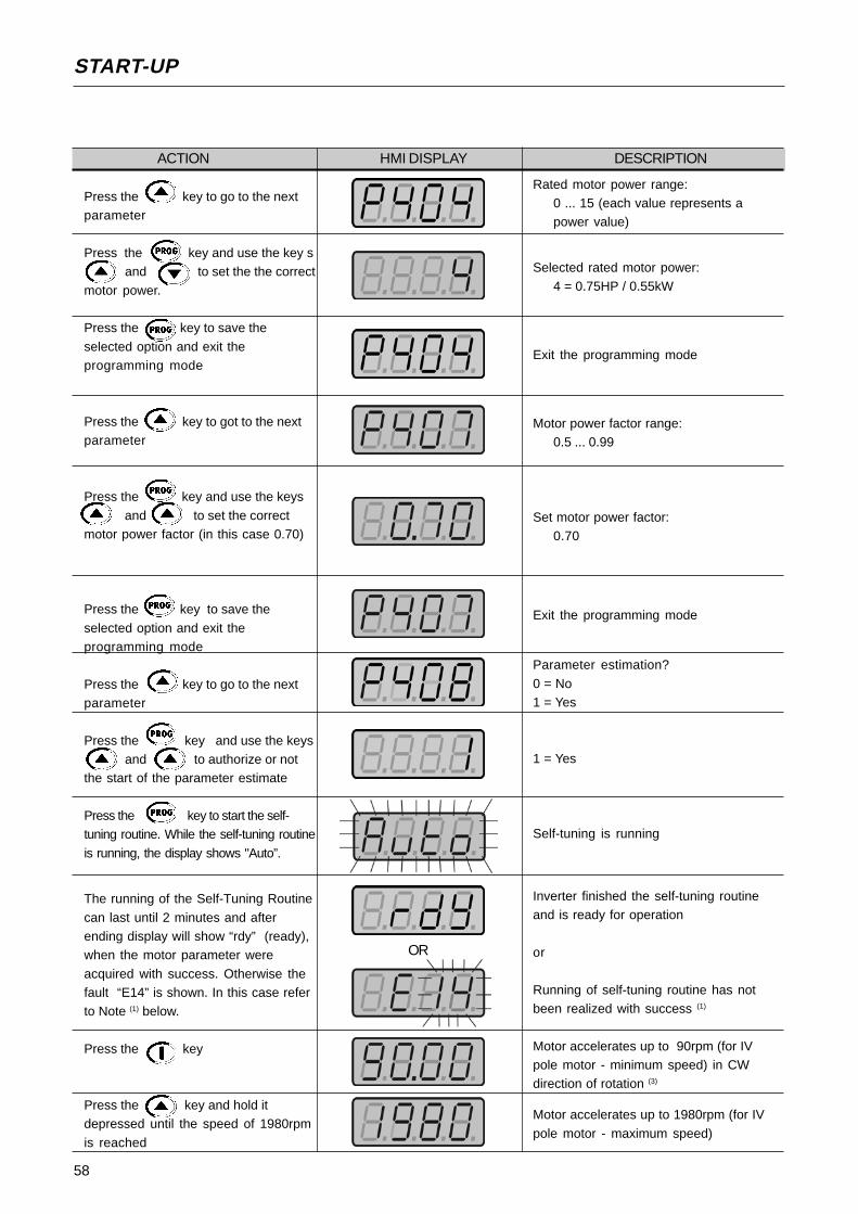
58
START-UP
ACTION HMI DISPLAY DESCRIPTION
Press the key to go to the nextparameter
Press the key and use the key sand to set the the correct
motor power.
Press the key to save the
selected option and exit theprogramming mode
Press the key to got to the nextparameter
Press the key and use the keys
and to set the correctmotor power factor (in this case 0.70)
Press the key to save the
selected option and exit theprogramming mode
Press the key to go to the nextparameter
Press the key and use the keysand to authorize or not
the start of the parameter estimate
Press the key to start the self-tuning routine. While the self-tuning routine
is running, the display shows "Auto”.
The running of the Self-Tuning Routine
can last until 2 minutes and afterending display will show “rdy” (ready),when the motor parameter were
acquired with success. Otherwise thefault “E14” is shown. In this case referto Note (1) below.
Press the key
Press the key and hold itdepressed until the speed of 1980rpm
is reached
Rated motor power range:0 ... 15 (each value represents apower value)
Selected rated motor power:4 = 0.75HP / 0.55kW
Exit the programming mode
Motor power factor range:0.5 ... 0.99
Set motor power factor:0.70
Exit the programming mode
Parameter estimation?
0 = No1 = Yes
1 = Yes
Self-tuning is running
Inverter finished the self-tuning routineand is ready for operation
or
Running of self-tuning routine has notbeen realized with success (1)
Motor accelerates up to 90rpm (for IVpole motor - minimum speed) in CWdirection of rotation (3)
Motor accelerates up to 1980rpm (for IV
pole motor - maximum speed)
OR

59
START-UP
NOTE!The last speed reference value set via key and keys
is saved.If you wish to change this value before enabling of inverter, change thevalue of the Parameter P121 - Keypad Reference;
The self-tuning routine can be cancelled by pressing the key.
NOTES:(1) If during the running of the Self-Tuning Routine the display shows E14,
this means that the motor parameters were not acquired correctly by theinverter. The most common reason for this fault may be that the motor has
not been coupled to the inverter output. However motors with very lowercurrents than the used inverter, or incorrect motor connection may alsocause the fault E14. In this case, operate the inverter in V/F mode (P202=0).
When the motor is not connected and the fault condition E14 is indicated,proceed as follows:
Switch off the inverter. Wait at least 5 minutes to allow a complete dischargeof the capacitors.Connect the motor to the inverter output.
Switch on the inverter.Set P000=5 and P408=1.Follow from now on the start-up procedures described in Section 4.3.3.
(2) For each inverter type, the parameters P399...P407 are set automatically to the rated motor data, considering a standard WEG motor, IV poles,60Hz.
When different motors are used, you must set the parameters manually,according to the motor nameplate data.
(3) If the direction of rotation of the motor is not correct, switch off the inveter.
Wait at least 5 minutes to allow a complete discharge of the capacitorsand then swap any two wires at the motor output.
(4) If fault E01 occurs during deceleration, you must increase the deceleration
time at P101/P103.
ACTION HMI DISPLAY DESCRIPTION
Press the key
Press key
Press the key and hold it
depresed
Release the key
Motor decelerates(4) tom 0 rpm and thereverses the direction of rotation
accelerating back to 1980rpm
Motor decelerates down to 0 rpm
Motor accelerates from 0 rpm up to theJOG speed set at P122.Ex: P122 = 5.00Hz that corresponds to
150rpm for IV-pole motor.Reverse (CCW) direction of rotation
Motor decelerates down to 0 rpm

60
KEYPAD (HMI) OPERATION
This chapter describes the CFW-08 operation via standard keypad orHuman-Machine Interface (HMI), providing the following information:
general keypad description (HM)I;use of the keypad;parameter programming;description of the status indicators.
5.1 KEYPAD (HMI)DESCRIPTION
The standard CFW-08 keypad has a LED display with 4 digits of 7segments, 4 status LEDs and 8 keys. Figure 5.1 shows the front view ofthe keypad and indicates the position of the display and the status LEDs.
LED Display
Green Led "Local"
Red Led "Remote"
Led "FWD"
Led "REV"
Figure 5.1 - CFW-08 standard keypad
Functions of the LED Display:The LED display shows the fault codes and drive status (see QuickParameter Reference, Fault and Status), the parameter number and itsvalue. For units of current, voltage or frequency, the LED display showsthe unit in the right side digit [U = Volts, A = Ampères, o = Celsius Degree(oC)]
Functions of the “Local” and “Remote” LEDs:
Inverter in Local Mode:Green LED ON and red LED OFF.
Inverter in Remote Mode:Green LED OFF and red LED ON.
Functions of the FWD/REV LEDs - Direction of RotationRefer to Figure 5.2
CHAPTER 5

61
KEYPAD (HMI) OPERATION
Figure 5.2 - Direction of rotation (FWD/REV) LEDs
OFF
ON
FLASHING
Basic Functions of the Keys:
Starts the inverter via acceleration ramp.
Stops (disables) the inverter via deceleration ramp.Also resets inverter after a fault has occurred.
Toggles the LED display between parameter number and its value(number/value).
Increases the frequency, the parameter number or the parameter value.
Decreases the frequency, the parameter number or the parameter value.
Reverses the direction of motor rotation between Forward/Reverse
Toggles between the LOCAL and REMOTE modes of operation .
Performs the JOG function when pressed. Any DI programmed for Gene-ral Enable (if any) must be closed to enable the JOG function.
The keypad is used for programming and operating the CFW-08, allowingthe following functions:
indication of the inverter status and operation variables;fault indication and diagnostics;viewing and programming parameters;operation of the inverter (keys , , , and )
and speed reference setting (keys and ).
5.2 USE OF THE KEYPADHMI
FWD/REVcontrolselection
FWD /REV
HMI LEDSituation
Forward
Reverse
Forward
t
t
t

62
KEYPAD (HMI) OPERATION
5.2.1 KeypadOperation
All functions relating to the CFW-08 operation (Start/Stop, Direction ofRotation, JOG, Increment/Decrement of the Speed (Frequency) Reference,and selection of LOCAL/REMOTE mode) can be performed through theHMI selection. For factory default programming of the inverter, all keypadkeys are enabled when the LOCAL Mode has been selected. These samefunctions can be performed through digital and analog inputs. Thus youmust program the parameters related to these corresponding inputs.
NOTE!The control keys , and are only enabled if:
P229=0 for LOCAL Mode operationP230=0 for REMOTE Mode operation
The key depends of the parameters above and if:P231=2
Keypad keys operation description:
When enabled (P220 = 2 or 3), selects the control input and the speedreference (speed) source, toggling between LOCAL and REMOTE Mode.
When pressed, starts the motor according to acceleration ramp up to thespeed (frequency) reference. The function is similar to thatperformed through digital input START/STOP, when it is closed (enabled)and maintained enabled.
Stop disables the inverter via deceleration Ramp.The Function is similarto that performed through digital input START/STOP, when it is open(disabled) and maintained disabled.
When the JOG key is pressed, it accelerates the motor according to theacceleration ramp up to the JOG speed programmed in P122.This key is only enabled when the inverter digital inputs, programmed togeneral enable (if any) are closed.
When enabled (refer to the note above), reverses the motor direction ofrotation.
Motor speed (frequency) setting: these keys are enabled for speed settingonly when:
the speed reference source is the keypad (P221 = 0 for LOCAL Modeand/or P222 = 0 for REMOTE Mode);the following parameter content is displayed: P002, P005 or P121.
Parameter P121 stores the speed reference set by these keys.
When pressed, it increases the speed (frequency) reference.
When pressed, it decreases the speed (frequency) reference.
63
KEYPAD (HMI) OPERATION
Inverter is READY to be started.
Line voltage is too low for inverter operation(undervoltage condition).
Inverter is in a Fault condition. Fault code is flashingon the display. In our example we have the faultcode E02 (refer to chaper Maintenance).
Inverter is applying a DC current on the motor (DCbraking) according to the values programmed atP300, P301 and P302 (refer to Chapter 6).
Inverter is running self-tuning routine to identify motorparameters automatically. This operation is controlledby P408 (refer to Chapter 6).
5.2.2 Inverter Status
5.2.3 Read-Only Variables
NOTE!The display also flashes in the following conditions, besides the faultconditions:
trying to change a parameter value when it is not allowed.inverter in overload condition (refer to Chapter Maintenance).
Parameters P002 to P099 are reserved for the display of read-only values.The factory default display when power is applied to the inverter is P002(frequency proportional value in V/F control mode and motor speed in rpmin vector control mode). Parameter P205 defines the initial monitoringparameter, i.e., defines the read-only variable that will be displayed whenthe inverter is powered up. For further information refer to P205 descriptionin Chapter 6.
Reference BackupThe last frequency reference set by the keys the andis stored when inverter is stopped or the AC power is removed, providedP120 = 1 (reference backup active is the factory default). To change thefrequency reference before starting the inverter, the value of the parameterP121, must be changed.
64
KEYPAD (HMI) OPERATION
NOTE!(1) For parameters that can be changed with the motor running, the
inverter will use the new value immediately after it has been set. Forparameters that can be changed only with motor stopped, the inverterwill use this new value only after the key is pressed.
(2) By pressing the key after the reprogramming, the newprogrammed value will be stored automatically and will remain storeduntil a new value is programmed.
5.2.4 Parameter Viewing andProgramming
All CFW-08 settings are made through parameters. The parameter areshown on the display by the letter P followed by a number:Exmple (P101):
101 = Parameter Number
Each parameter is associated with a numerical value (parameter value),that corresponds to the selected option among the available ones for thisparameter.
The parameter values define the inverter programming or the value of avariable (e.g.: current, frequency, voltage).For inverter programming youshould change the parameter content(s).
To allow the reprogramming of any parameter value (except for P000 andP121) it is required to set P000 = 5.Otherwise you can only read the parameter values, but not reprogramthem. For more details, see P000 description in Chapter 6.
ACTION HMI DISPLAY DESCRIPTION
Turn ON the inverter
Press the key
Use the keys and to
reach P100
Press the key
Use the keys and keys
Press the key
Inverter is ready to be started
Select the desired parameter
Numerical value associated with theparameter (4)
Set the new desired value (1) (4)
(1) (2) (3)

65
KEYPAD (HMI) OPERATION
Table 5.1 - Incompatibility of parameters - E24
P265=3 (JOG) and other(s) DI(s) ≠ Start/Stop or forward run and reverse or FWD run and REV runusing Ramp #2
P266=3 (JOG) and other(s) DI(s) ≠ Start/Stop or forward run and reverse or FWD run and REV runusing Ramp #2Two or more parameters among P264, P265 and P266 equal to 1 (LOC/REM)
P265=13 and P266=13 (flying start disable)P265=10 and P266=10 (reset)P263=14 and P264≠14 or P263≠14 and P264=14 (3-wire - Start/Stop)
Two or more parameter among P264, P265 and P266 equal to 0 (FWD/REV)P263=8 and P264≠8 and P264≠13P263≠8 and P263≠13 and P264=8
P263=13 and P264≠8 and P264≠13P263≠8 and P263≠13 and P264=13P263=8 or 13 and P264=8 or 13 and P265=0 or P266=0
P263=8 or 13 and P264=8 or 13 and P231≠2P221=6 or P222=6 and P264≠7 and P265≠7 and P266≠7 (multispeed)P221≠6 or P222≠6 and P264=7 or P265=7 or 14 or P266=7
P265=14 and P221≠6 and P222≠6P221=4 or P222=4 and P265≠5 and P266≠5 (EP)P221≠4 or P222≠4 and P265=5 and P266=5
P295 incompatible to the inverter model (size and voltage).P300≠0 and P310= 2 or 3 (DC braking and ride-through active)P203=1 (PID special function) and P221 or P222=1, 4, 5, 6, 7 or 8
P265=6 and P266=6 (ramp #2)P221=2 or 3 or 7 or 8 and standard inverterP222=2 or 3 or 7 or 8 and standard inverterP265=13 and P266=3 (flying start disable)P221=4 or P222=4 (reference = P.E.) and P265≠5 and 16 and P266≠5 and 16 (DI3 and DI4 not programmed to P.E.).P265=5 or 16 or P266=5 or 16 (DI3 or DI4 programmed to P.E.) and P221≠4 and P222≠4 (reference≠P.E.).P265=6 or P266=6 (DI3 or DI4 programmed to the 2nd ramp) and P263=13 or P264=13 (fwd/rev with 2nd
ramp).
(3) If the last programmed value in the parameter is not functionallycompatible with other parameter values already programmed, E24 -Programming Error - will be displayed.Example of programming error:Programming of two digital inputs (DI) with the same function. Refer toTable 5.1 for list of programming errors that can generate an E24Programming Error.
(4) To allow the reprogramming of any parameter value (except for P000and P121) it is required to set P000 = 5.Otherwise you can only read the parameter values, but not reprogramthem. For more details, see P000 description in Chapter 6.

66
This chapter describes in detail all CFW-08 parameters and functions.
6.1 SYMBOLS Please find below some symbols used in this chapter:AIx = Analog input number x.AO = Analog output.DIx = Digital input number x.F* = Frequency reference. This is the frequency value that indicates thedesired motor speed at the inverter output.Fe = Input frequency of the acceleration and deceleration ramp.Fmax = Maximum output frequency, defined at P134.Fmin = Minimum output frequency, defined at P133.Fs = Output frequency - frequency applied to the motor.Inom = Rated inverter output current (rms), in Ampères (A). This value isdefined in P295.Is = Inverter output current.Ia = Active current at inverter output, i.e., it is the compoment of the totalmotor current proportional to active electric power absorbed by the motor.RLx = Relay output number x.Ud = DC link voltage in the DC link circuit.
This section describes the main concepts related to the CFW-08 frequencyinverter.
As already informed in section 2.3, CFW-08 has in the same product aV/F control and a sensorless vector control (VVC: “voltage vector control”).The user must choose one of them. Please find below a description ofeach control mode.
This control mode is based on the constant V/F curve(P202=0 - linear V/F curve). Its performance is limited at low frequencies as function of thevoltage drop in the stator resistance, that causes a significant magneticflow reduction in the motor air gap and consequently reducing the motortorque. This deficiency should be compensated by using manual andautomatic boost torque (IxR compensations), that are set manually anddepend on the user experience.In most applications (for instance: centrifugal pumps and fans) the settingof these functions is enough to obtain the required performance. But thereare applications that require a more sophisticated control. In these casesit´s recommended the use of the sensorless vector control, that will bedescribed in the section below.In V/F control, the speed regulation, that can be obtained by settingproperly slip compensation can be maintained within 1 to 2% of the ratedspeed. For instance, for a IV pole motor/60Hz, the minimum speed variationat no load condition and at rated load can be maintained between 18 and36rpm.
6.2 INTRODUCTION
6.2.1 Control Modes
6.2.2 V/F Control
DETAILED PARAMETER DESCRIPTION
CHAPTER 6

67
DETAILED PARAMETER DESCRIPTION
There is still a variation of the linear V/F control: the quadratic V/F control.This control mode is suitable for applications like centrifugal pumps andfans (loads with quadratic torque x speed characteristics), since it enablesa motor loss reduction, resulting in an additional energy saving by usingan inverter.For more details about the V/F control mode, please refer to the descriptionof the parameters P136, P137, P138, P142 and P145.
Inverter performance improvements can be achieved when the sensorlessvector control is selected (P202=2).The CFW-08 vector control is sensorless, i.e., it does not require a signalof the speed feedback through tachogenerator or encoder coupled onmotor shaft.To maintain the magnetic flow in the motor air gap constant, andconsequently the motor torque, within the whole speed variation range(from zero up to the field weakening point), a sophisticated control algorithmis used that considers the mathematic model of the induction motor.Thus one can maintain the mangetic flow in the motor air gap approximatelyconstant at frequencies down to approximately 1 Hz.In vector control mode one can obtain a speed regulations about 0.5%(relating to the rated speed). Thus, for instance, for a IV pole motor/60Hzone can obtain a speed variation in the range of 10rpm (!).Other advantage of the vector control is its easy setting procedure.The user needs only to enter in the parameters P399 and 407 the informationabout the used motor (nameplate data) and runs the self-tuning routine(by setting P408=1) and the inverter configures itself to the requiredapplication. So the inverter is ready to be operated in an optmized manner.For more information, refer to the description of the following parameters:P178 and P399 to P409.
The frequency reference (i.e., the desired output frequency, or alternatively,the motor speed) can be defined in several ways:
the keypad - digital reference that can be changed through the keypad(HMI), by using the keys and (see P221, P222 andP121);analog input - the analog input AI1 (XC1:6) or the AI2 (XC1:8) can beused, or both (see P221, P222 and P234 to P240);multispeed - up to 8 preset digital references (see P221, P222 andP124 to P131);electronic potentiometer (EP) - another digital reference, its valueis defined by using 2 digital inputs (DI3 and DI4) - see P221, P222,P265 and 266;via serial.
Figure 6.1 shows through a diagram block the frequency reference definitionto be used by the inverter.The block diagram in Figure 6.2 shows the inverter control.
6.2.3 Vector Control (VVC)
6.2.4 Frequency ReferenceSources

68
DETAILED PARAMETER DESCRIPTION
Figure 6.1 - Block diagram of the frequency reference
NOTE!AI2 is only available in CFW-08 Plus version.DIs ON when connected to 0V (XC1:5).When F*<0 one takes the module of F* and reverses the direction ofrotation (if this is possible - P231=2 and if the selected control is notforward run/reverse run.
RS-232
PC, CLP,MIW-02
KEYPADREFERENCE
(P121)
HMI-CFW08-RPor
HMI - CFW08-RS
KCS-CFW-08
P124...P131P264=7P265=7P266=7
MULTISPEED
Accel.
Enabling Function
P265=5P266=5
Decel.
InverterDisabled
ELECTRONIC POTENTIOMETER (EP)
AI2
AI1
DI4
DI3
DI21
2
3
4
5
6
7
8
9
10
11
12
XC1
AI1
P235
AI2
P239
P238 P134
P234 P134
P236
P240
2 or 3 - AI2
7 - Add AI>0
8 - Add AI1
1 - AI
4 - EP
6 - Multispeed
5 - Serial
0 - Keypad
Frequency ReferenceSelection
P221 or P222
F*
DigitalReferences
AnalogReferences
P131P130P129P128P127P126P125P124
000 001 010 011 100 101 110 111
100%
P239=0
P239=102V/4mA 10V/20mA
100%
P235=0
P235=1
02V/4mA 10V/20mA
0V
Reset
HMI-CFW08-P

69
DETAILED PARAMETER DESCRIPTION
Fe
Command viaDigital Input
(DI)
Acceleration&Deceleration
Ramp #2
Acceleration &Deceleration
Ramp
P102 P103
P100 P101
DC LinkRegulation
P151
P151
Ud
P133 P134
FrequencyReference
Limits
P202 P295
Inverter Control(V/F or Vector)
P136, P137,P138, P142, P145
Motor Parameters(P399...P409)
P178
Vs
PWM
P169
Is
P169Is
OutputCurrentLimiting
I
V s
Ud
PowerSupply
IM3Ø
Is
NOTE!In V/F control mode (P202=0 or 1), Fe = F* (see Fig. 6.1) if P138=0(slip compensation disabled). If P138≠0, see Figure 6.9 for the relationbetween Fe and F*.In vector control mode (P202) always Fe = F* (see Figure 6.1).
Figure 6.2 - Inverter block diagram

70
DETAILED PARAMETER DESCRIPTION
6.2.5 Commands
6.2.6 Local/RemoteOperation Modes
The inverter has the following commands: PWM pulse enabling/disabling,definition of the direction of rotation and JOG.As the reference, the inverter commands can de defined in several ways.
The command sources are the following:
via keypad - keys , , and ;via control terminals (XC1) - digital inputs;via serial interface.
The inverter enabling and disabling commands can be defined as follows:
via keypad and of the HMI;via serial;start/stop (terminals XC1 - DI(s) - see P263 ... P266);general enable (terminals XC1 - DI(s) - see P263 ... P266);forward runIt defines also the direction of rotation;ON/OFF (3-wire controls) (terminals XC1 - DIs - see P263 e P264).
The definition of the direction of rotation can be defined by using:
the key of the keypad;serial;digital input (DI) programmed for FWD/REV (see P264 ... P266);digital inputs programmed as FWD / REV, that defines both inverterenabling or disabling and direction of rotation (see P263 e P264);analog input - when the reference is via analog input and a negativeoffset is programmed (P236 or P240<0), the reference mayassume negative values, thus reversing the direction of the motorrotation.
User can define two different conditions relating to the frequency referencesource and the inverter commands: these are the local and the remoteoperation modes.Figure 6.3 shows the local and remote operation modes in a block diagram.With the factory setting in local mode the inverter can be controlled byusing the keypad, while in remote mode all controls are via terminals(XC1).

71
DETAILED PARAMETER DESCRIPTION
Read-Only Parameters Variables that can be viewed on thedisplay, but can not be changed by theuser.
Regulation Parameters Programmable values used by theCFW-08 functions.
Configuration Parameters They define the inverter characteristics,the functions to be executed, as well asthe input/output functions of the controlboard.
Motor Parameters Data about the applied motor: dataindicated on the motor nameplate andthose obtained during the running of theself-tuning routine.
Special Function Parameters Here are included parameters related tospecial functions, like PID regulator.
Figure 6.3 - Block diagram of the local and remote operation mode
LOCAL
FrequencyReference
P221
ControlsP229 (stop/run,FWD/REV and
JOG)
0 Keypad(HMI-CFW08-P andHMI-CFW08-RS)1 AI12 or 3 AI24 EP5 Serial6 Multispeed7 Add AI8 Add AI>0
0 HMI-CFW08-Pkeypad1 Bornes XC1 (DIs)2 Serial or HMI-CFW08-RS keypad
REMOTE
FrequencyReference
P222
ControlsP230 (start/stop,
FWD/REV andJOG)
0 Keypad(HMI-CFW08-P andHMI-CFW08-RS)1 AI12 or 3 AI24 EP5 Serial6 Multispeed7 Add AI8 Add AI>0
0 HMI-CFW08-Pkeypad1 Termin. XC1 (DIs)2 Serial orHMI-CFW08-RSkeypad
REFERENCE
COMMANDS
Local/Remote Selection (P220)+
Local/Remote Command
( , DI, serial, etc)
6.3 PARAMETERLISTING
In order to simplify the explanation, the parameters have been grouped bycharacteristics and functions:
F*
72
DETAILED PARAMETER DESCRIPTION
Range[Factory Setting]
Parameter Unit Description / Notes
P000 0...999Access Parameter [ 0 ]
1
6.3.1 Access and Read Only Parameters - P000 ... P099
P002 0...6553Frequency [ - ]Proportional Value 0.01 (<100.0);
0.1 (<1000);1 (>999.9)
P003 0...1.5 x Inom
Output Current [ - ](Motor) 0.01A (<10.0A);
0.1A (>9.99A)
P004 0...862VDC Link Voltage [ - ]
1V
Releases the access to change the parameter values.The password is 5.The use of the password is always active.
Indicates the value of P208 x P005.When the vector control mode is used (P202=2), P002 indicatesthe actual motor speed in rpm.In case of different scales and units, use P208.
Indicates the inverter output current in Amps. (A).
Indicates the inverter DC Link voltage in Volts (V).
P005 0...300HzOutput Frequency [ - ](Motor) 0.01Hz (<100.0Hz);
0.1Hz (>99.99Hz)
Indicates the inverter output frequency in Hertz (Hz).
P007 0...600VOutput Voltage [ - ](Motor) 1V
Indicates the inverter output voltage in Volts (V).
P008 25...110oCHeatsink Temperature [ - ]
1oC
Indicates the current power at the heatsink in Celsius degrees(°C).The inverter overtemperature protection (E04) acts whenheatsink temperature reaches:
Inverter1.6-2.6-4.0-7.0A/200-240V1.0-1.6-2.6-4.0A/380-480V
7.3-10-16A/200-240V2.7-4.3-6.5-10A/380-480V
13-16A/380-480V
P008 [°C] @ E0410390
90103103
P009 0.0...150.0%Motor Torque [ - ]
0.1%
Indicates the torque developed by motor in, in percent (%) relatingto the set rated motor torque.The rated motor torque is defined by the parameters P402(motor speed) and P404 (motor power). I.e.:
where Tnom
is given in kgf.m, Pnom
is the rated motor power in watts-HP - (P404), and n
nom is the rated motor speed in rpm - P402.
Tnom
= 716 . Pnom
nnom
P014 00...41Last Fault [ - ]
-
Indicates the code of the last occured fault.Section 7.1 shows a list of possible faults, their code numbersand possible causes.
Thisparameter is onlyshown in vectorcontrol(P202=2)
73
DETAILED PARAMETER DESCRIPTION
Range[Factory Setting]
Parameter Unit Description / Notes
P023 x.yzSoftware Version [ - ]
-
P040 0...P528Process [ - ]Variable (PID) 1
P100 0.1...999sAcceleration [ 5.0s ]Time #1 0.1s (<100);
1s (>99.9)P101 0.1...999sDeceleration [ 10.0s ]Time #1 0.1s (<100);
1s (>99.9)P102 0.1...999aAcceleration [ 5.0s ]Time #2 0.1s (<100);
1s (>99.9)P103 0.1...999sDeceleration [ 10.0s ]Time #2 0.1s (<100);
1s (>99.9)
Indicates the software version installed in the DSP memory locatedon the control board.Parameter P040, P203, P520 to P528 are only available from thesoftware version V3.50 on.
Indicates the value of the process variable used as PID feedback,in percent (%).The PID function is only available from the software version V3.50on.The indication unit can be changed through P528.See detailed description of the PID regulator in Section 6.3.5 -Special Function Parameters.
This set of parameters defines the time to accelerate linearly fromzero up to the rated frequency and to decelerate linearly fromthe rated frequency down to zero.The rated frequency is defined by parameter:- P145 in V/F control (P202=0 ou 1);- P403 in vector control (P202=2).When factory setting is used, inverter always follows the time definedin P100 and P101.Ramp #2 is used, the the acceleration and deceleration timesfollow the values programmed at P102 and P103, use a digital input.See parameters P263 ... P265.Depending on the load inertia, too short acceleration times candisable the inverter due to overcurrent (E00).Depending on the load inertia, too short deceleration times candisable the inverter due to overvoltage (E01). For more details,refer to P151.
6.3.2 Regulation Parameters - P100 ... P199
P104 0...2S Ramp [ 0 - Inactive ]
-
The ramp S reduces mechanical stress during the acceleration anddeceleration of the load.
Figure 6.4 - S or linear ramp
It is recommended to use the S ramp with digital frequency/speedreferences.
Accel Time(P100/102)
Decel Time (P101/103)
P1040
12
Ramp SInactive
50%100%
Output frequency(Motor speed)
Linear
t (s)
50% ramp S
100% ramp S
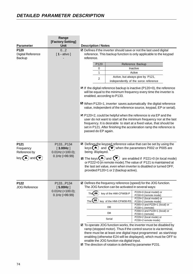
74
DETAILED PARAMETER DESCRIPTION
Range[Factory Setting]
Parameter Unit Description / NotesP120 0...2Digital Reference [ 1 - ativo ]Backup -
Defines if the inverter should save or not the last used digitalreference. This backup function is only applicable to the keypadreference.
P1200
1
2
Reference BackupInactive
ActiveActive, but always give by P121,
independently of the sorce reference
If the digital reference backup is inactive (P120=0), the referencewill be equal to the minimum frequency every time the inverter isenabled, according to P133.
When P120=1, inverter saves automatically the digital referencevalue, independent of the reference source, keypad, EP or serial).
P120=2, could be helpful when the reference is via EP and theuser do not want to start at the minimum frequency nor at the lastfrequency. It is desirable to start at a fixed value, that should beset in P121. After finishing the acceleration ramp the reference ispassed do EP again.
P121 P133...P134Frequency [ 3.00Hz ]Reference by 0.01Hz (<100.0);
key and0.1Hz (>99.99)
Defines the keypad reference value that can be set by using thekeys and when the parameters P002 or P005 arebeing displayed.
The keys and are enabled if P221=0 (in local mode)or P222=0 (in remote mode).The value of P121 is maintained atthe last set value, even when inverter is disabled or turned OFF,provided P120=1 or 2 (backup active).
The key of the HMI-CFW08-P
The key of the HMI-CFW08-RS
DI3
DI4
Serial
Defines the frequency reference (speed) for the JOG function.The JOG function can be activated in several ways:
P122 P133...P134JOG Reference [ 5.00Hz ]
0.01Hz (<100.0);0.1Hz (>99.99)
P229=0 (local model) orP230=0 (remote mode)P229=2 (local model) orP230=2 (remote mode)P265=3 and P229=1 (local) orP230=1 (remote)P266=3 and P229=1 (local) orP230=1 (remote)P229=2 (local mode) orP230=2 remote mode)
To operate JOG function works, the inverter must be disabled byramp (stopped motor). Thus if the control source is via terminal,there must be at least one digital input programmed as start/stopenabling (otherwise E24 will be displayed), which must be OFF toenable the JOG function via digital input.The direction of rotation is defined by parameter P231.

75
DETAILED PARAMETER DESCRIPTION
Multispeed is used when the selection of a number up to 8 pre-programmed speeds is desired.It allows the control of the output speed by relating the valuesprogrammed by the parameters P124...P131, according to thelogical combination of the digital inputs programmed for multispeed.Activation of the multispeed function:- ensure that the reference source is given by the multispeed
function, i.e., set P221=6 in local mode or P222=6 in remotemode;
- program one or more digital inputs to para multispeed, accordingto table below:
DI ProgrammingDI2 P264 = 7
DI3 P265 = 7DI4 P266 = 7
The frequency reference is defined by the status of the digital inputsprogrammed to multispeed as shown in table below:
The multispeed function has some advantages for the stabibilty ofthe fixed preprogrammed references and the immunity againstelectrical noises (digital references and insulated digital inputs).
(1) This parameter can be changed only with the inverter disabled (motor stopped).
Range[Factory Setting]
Parameter Unit Description/NotesP124 (1) P133...P134Multispeed Ref. 1 [ 3.00Hz ]
0.01Hz (<100.0);0.1Hz (>99.99)
P125 (1) P133...P134Multispeed Ref. 2 [ 10.00Hz ]
0.01Hz (<100.0);0.1Hz (>99.99)
P126 (1) P133...P134Multispeed Ref. 3 [ 20.00Hz ]
0.01Hz (<100.0);0.1Hz (>99.99)
P127 (1) P133...P134Multispeed Ref. 4 [ 30.00Hz ]
0.01Hz (<100.0);0.1Hz (>99.99)
P128 (1) P133...P134Multispeed Ref. 5 [ 40.00Hz ]
0.01Hz (<100.0);0.1Hz (>99.99)
P129 (1) P133...P134Multispeed Ref. 6 [ 50.00Hz ]
0.01Hz (<100.0);0.1Hz (>99.99)
P130 (1) P133...P134Multispeed Ref. 7 [ 60.00Hz ]
0.01Hz (<100.0);0.1Hz (>99.99)
P131 (1) P133...P134Multispeed Ref. 8 [ 66.00Hz ]
0.01Hz (<100.0);0.1Hz (>99.99)
DI2 DI3 DI4 Freq. Reference
Open Open Open P124
Open Open 0V P125
Open 0V Open P126
Open 0V 0V P127
0V Open Open P128
0V Open 0V P129
0V 0V Open P130
0V 0V 0V P131
8 speeds 4 speeds 2 speeds
Figure 6.5 - Time diagram of the multispeed function
Accelerationramp
Time0V
DI2
DI3
DI4
open0V
open0V
open
P124
P125
P126
P127
P128
P129
P130
P131Outputfrequency

76
DETAILED PARAMETER DESCRIPTION
Range[Factory Setting]
Parameter Unit Description / NotesP133 (1) 0.00...P134Minimum Frequency [ 3.00Hz ](F
min) 0.01Hz (<100.0);
0.1Hz (>99.99)
P134 (1) P133...300.0Maximum Frequency [ 66.00Hz ](Fmax) 0.01Hz (<100.0);
0.1Hz (>99.99)
Defines the maximum and minimum output frequency (motor)when inverter is enabled.It is valid for any type of speed reference.The parameter P133 defines a dead zone when analog inputs areused - see parameters P234 ... P240.P134 and the gain and offset of the analog input(s) (P234, P236,P238 and P240) define the scale and the range of the speedvariation via analog input(s). For more details see parametersP234 ... P240.
P136 0.0...30.0%Manual Torque [ 5.0% forBoost 01.6-2.6-4.0-7.0A/(IxR Compensation) 200-240V and
1.0-1.6-2.6-4.0A/ 380-480V;
2.0% for7.3-10-16A/
200-240V and2.7-4.3-6.5-10A/
380-480V;1.0% for
13-16A/380-480V ]0.1%
Compensates the voltage drop due to the motor stator resistance.It acts at low speeds by increasing the inverter output voltage, in order to maintain a constant torque during the V/F operation.The best setting is to program the lowest value for P136 that stillpermits the motor start satisfactorily. If the value is higher thanrequired, an inverter overcurrent (E00 or E05) may occur due tohigh motor currents at low speeds.
This parame-ter is only availablein V/F control(P202=0 or 1)
Figure 6.6 - V/F curve and details of the manual torque boost (IxR compensation)
Output Voltage(% of the line voltage)
Output Voltage(% of the line voltage)
P142
P136xP142
0 P145
OutputFrequency
P142
P136
0 P145
OutputFrequency
(a) P202=0 (b) P202=1
P137 0.00...1.00%Automatic Torque [ 0.00 ]Boost -(Automatic IxRCompensation)
This parame-ter is shown only inV/F control(P202=0 or 1)
The automatic torque boost compensates for the voltage drop inthe stator resistance as a function of the active motor current.The criteria for setting P137 are the same as for the parameterP136.
(1) This parameter can be changed only with the inverter disabled (motor stopped).

77
DETAILED PARAMETER DESCRIPTION
Range[Factory Setting]
Parameter Unit Description / Notes
Figure 6.7 - Block diagram of the automatic torque boost function
CompensationZone
Maximum(P142)
Output Voltage
OutputFrequency
Field Weakening(P145)
4Hz0
Figure 6.8 - V/F curve with automatic torque boost(automatic IxR compensation )
SpeedReference (F*)
Output ActiveCurrent (Ia)
Filer
AutomaticTorque Boost
P137
ManualTorque Boost
P136
P007Motor
Voltage
P138 0.0...10.0%Slip Compensation [0.0]
0.1%
This parame-ter is only availablein V/F control(P202=0 or 1)
The parameter P138 is used in the motor slip compensation function.
This function compensates the drop of the motor speed due toload, which is a inherent characteristic relating to the operationprinciple of the induction motor.
This speed drop is compensated by increasing the output frequency(and voltage) (applied to the motor) as a function of the increase ofthe active motor current, as shown in the block diagram and in theV/F curve below.
SlipCompensation
Output ActiveCurrent (Ia)
FrequencyReference (F*)
Ramp Input Frequency (Fe)
F
Filter P138
Figure 6.9 - Block diagram of the slip compensation function

78
DETAILED PARAMETER DESCRIPTION
Range[factory Setting]
Parameter Unit Description / Notes
Figure 6.10 - V/F curve with slip compensation
Output Voltage
(function ofthe motor
load)
OutputFrequency
To set the parameter P138 use the following procedure:- run the motor without load up to approximately half of the application top speed;- measure the actual motor or equipment speed;- apply rated load to equipment;- increase parameter P138 until the speed reaches its no-load speed.
P142(1) 0...100%Maximum OutputVoltage [ 100% ]
1%
P145(1) P133...P134Field Weakening [ 60.00Hz ]Frequency 0.01Hz (<100.0)(F
nom) 0.1Hz (>99.99)
Theseparameters areonly available inV/F control(P202=0 or 1)
Define the V/F curve used in V/Fcontrol (P202=0 or 1).These parameters allow changing the standard V/F curve definedat P202 - programmable V/F curve.P142 sets the maximum output voltage. This value is setas a percent of the inverter supply voltage.Parameter P145 defines the rated frequency of the motor used.The V/F curve relates the inverter output voltage and frequency(applied to the motor) and consequently the magnetizing flux of themotor.The programmave V/F curve can be used in special applicationswhere the motors used require a rated voltage and/or frequencydifferent than the standard ones. Examples: motor for 220V/400Hz and a motor for 200V/60Hz.Parameter P142 is also useful in appplications that requirerated voltage different from the inverter supply voltage. Example:440V line and 380V motor.
Figure 6.11 - Adjustable V/F curve
Output Voltage
OutputFrequencyP1450.1Hz
0
P142
(1) This parameter can be changed only with the inverter disabled (motor stopped).

79
DETAILED PARAMETER DESCRIPTION
Range[Factory Setting]
Parameter Unit Description / NotesP151 325...410VDC Link Voltage (line 200-240V)Regulation Level [ 380V ]
1V
564...820V(line 380-480V)
[ 780V ]1V
The DC link voltage regulation (ramp holding) avoids overvoltagetrips (E01) during deceleration of high inertia loads and/or shortdeceleration times.It acts in order to increase the deceleration time (according to load- inertia), thus avoiding the E01 activation.
E01 - Overvoltage
CI limitation
Cl voltageUd (P004)
Time
OutputFrequnecy
(Motorspeed)
rated Ud
P151
Time
Figure 6.12 - Deceleration curve with DC Link voltage limitation(regulation)
By this function an optimized deceleration time (minimum) isachieved for the driven load.This function is useful in applications with medium inertia that requireshort deceleration times.In case of overvoltage trip during the decelearation, you must reducegradually the value of P151 or increase the time of the decelerationramp (P101 and/or P103).The motor will not stop if the line is permanently withovervoltage (Ud>P151). In this case, reduce the line voltage,or increase the value of P151.If even with these settings the motor does not decelerate within therequired time, you will have the following alternatives- use the dynamic braking (for more details, see Item 8.20);- if inverter is being operated in V/F control, increase P136;- if inverter is being operated in vector control, increase P178.
NOTE!When dynamic braking is used, set P151 to the maximumvalue.
P156 0.2xPInom...1.3xPInom
Motor Overload [ 1.2xP401 ]Current 0.01A (<10.0A);
0.1A (>9.99A)
This function is used to protect the motor against overload(Ixt function - E05).The motor overload current is the current level above which the inverter will consider the motor operating under overload. The higherthe difference between the motor current and the overload current,the sooner the Ixt function - E05 - will act.
DC Linkvoltage

80
DETAILED PARAMETER DESCRIPTION
Range[Factory Setting]
Parameter Unit Description / Notes
Figure 6.13 - Ixt function – Overload detection
3,0
2,0
1,5
1,0
15 30 60 90Time (s)
Motor Current (P003)Overload Current
Prevents motor stalling during an overload. If motor load increasesits current will increase too. If the motor current attempts to exceedthe value set at P169, the motor speed will be decreased by followingthe deceleration ramp until the current becomes lower than P169.As soon as the overload condition disappears, the motor speed isresumed.
P169 0.2xPInom
...2.0xPInom
Maximum Output [ 1.5xP295 ]Current 0.01A (<10.0A);
0.1A (>9.99A)
Parameter P156 must be set from 10% to 20% higher than therated motor current (P401).Always P401 is changed, P156 is adjusted automatically to1.1xP401.
Figure 6.14 – Curves showing the actuation of the current limitation
Timeduring
cont. duty
Time
Motor Current
Deceleration ramp (P101/P103)
decel.ramp
accel.ramp
duringdeceleration
duringacceleration
accelerationramp
(P100/P102)
Speed
P169
The current limitation function is disabled when P169>1.5xP295.
P178 50.0...150.0%Rated Flux [ 100% ]
0.1% (<100%);1% (>99.9%)This
parameter is shownonly in vectorcontrol (P202=2)
Defines the flux in the motor air gap, when in vector control. It isexpressed as a percentage (%) of the nominal flux.Generally it is not necessary to change P178 of the default value(100%). But in some specific cases, different values at P178 maybe set.These conditions may be:- to increase the inverter torque capacity (P178>100%).
Examples:1) to increase the motor starting torque and thus ensure faster
motor starts;2) to increase the inverter braking torque and thus allow faster
stops, without using dynamic braking.- to reduce the inverter energy consumption (P178<100%).

81
DETAILED PARAMETER DESCRIPTION
Range[factory Setting]
Parameter Unit Description / NotesDefines the inverter control mode. Item 4.3 gives some guidelinesrelating to the selection of control type.
P202(1) 0...2Type of Control [ 0 - V/F linear ]
-
As shown in table above, there are 2 V/F control modes:
- Linear V/F control: this control mode ensures a flux in the motorair gap approximately constant from around 3Hz up to the fieldweakening (defined by the parameters P142 and P145).Thus in this speed range, an approximately constant torquecapacity is obtained. This control mode is recommended forbelt conveyors, extruding machines, etc.
- Quadratic V/F control: in this control mode the flux in the motor airgap is proportional to the output frequency up to the field weakeningpoint (defined at P142 and P145). Thus the torque capacity isa function of the quadratic speed. The main advantageof this type of control is the energy saving capability with variabletorque loads, due to the reduction of the motor losses(mainly due to motor iron losses and magnetic losses).
Main application fields for this type of control are: centrifugal pumps,fans, multimotor drivings.
6.3.3 Configuration Parameters - P200 ... P398
Output Voltage
P136=0
P142
0P145
OutputFrequency
Output Voltage
P136=0
P142
0P145
OutputFrequency
(a) Linear V/F (b) Quadratic V/F
Figure 6.15 -V/F control modes (scalar)
(1) This parameter can be changed only with the inverter disabled (motor stopped).
P2020
12
Type of ControlLinear V/F Control (scalar)
Quadratic V/F Control (scalar)Vector Control

82
DETAILED PARAMETER DESCRIPTION
Range[factory Setting]
Parameter Unit Description / Notes
Selects or not the special function of the PID regulator.P203(1) 0...1Special Function [ 0 - None ]Selection -
P20301
Special functionNone
PID regulator
See detailed description of PID regualator parameters (P520...P528)in Section 6.3.5.When P203 is changed to 1, P265 is changed automatically to 15(DI3 = manual/automatic).
Programs all parameters to the standard factory default, whenP204=5.The parameters P142 (max. output voltage), P145 (field weakeningfrequency), P295 (rated current), P308 (inverter address) and P399to P407 (motor parameters) are not changed when the factory defaultparameters are loaded through P204=5.
P204(1) 0...5Load Factory [ 0 ]setting -
Selects which of the parameters listed below will be shown on thedisplay as a default after the inverter has been powered up.
P205(1) 0...6Display [ 2 - P002 ]Default -Selection P205
012
34, 56
Read Parameter
P005 [Output Frequency (Motor)]P003 [Output Current (Motor)]P002 (Value Proportional to Frequency)
P007 [Output Voltage (Motor)]Not usedP040 (PID Process Variable)
In the event of a fault trip, except for E14, E24 and E41, the invertercan initiate an automatic reset after the time given by P206 iselapsed.If P206 2 Auto-Reset does not occur.If after Auto-Reset the same fault is repeated three timesconsecutively, the Auto-Reset function will be disabled. A fault isconsidered consecutive if it happens again within 30 seconds afterthe Auto-Reset. Thus if a fault occurrs four times consecutively,this fault remains indicated permanently (and inverter disabled).
P206 0...255sAuto-Reset Time [ 0 ]
1s≥
≥
(1) This parameter can be changed only with the inverter disabled (motor stopped).
The vector control allows a better performance regarding to torqueand speed control. The CFW-08 vector control operates withoutmotor speed sensor (sensorless). It must be applied when followingperformances are required:- better dynamics (faster accelerations and stoppings);- when a more accurate speed control is required;- when high torques at low speeds are required ( 5Hz).Examples: in positioning, such as load moving, packing machines,pumps, dosing machines, etc.The vector control can not be used in multimotor applications.
The performance of the vector control with a switching frequency of10kHz is not so good as when a switching frequency of 5kHz or2.5kHz is used. It is not possible to use a vector control with aswitching frequency of 15kHz.For more details about the vector control, refer to Item 6.2.3.
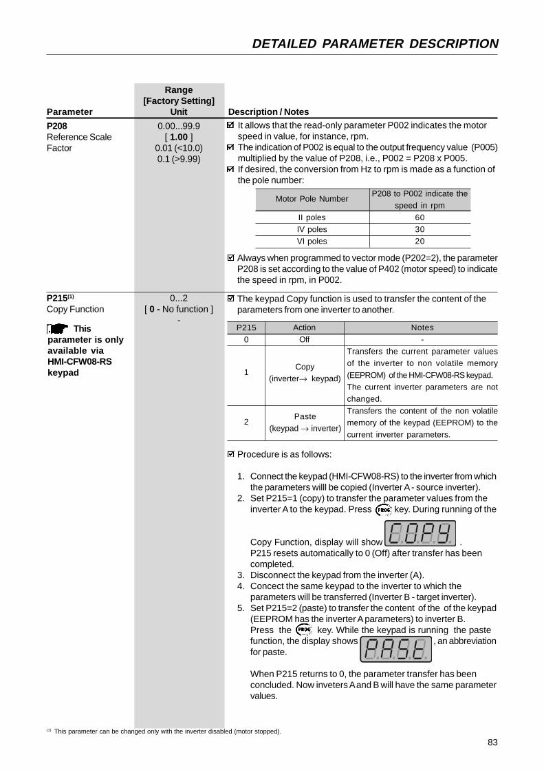
83
DETAILED PARAMETER DESCRIPTION
Range[Factory Setting]
Parameter Unit Description / Notes
Motor Pole Number
II polesIV polesVI poles
P208 to P002 indicate thespeed in rpm
603020
Always when programmed to vector mode (P202=2), the parameterP208 is set according to the value of P402 (motor speed) to indicatethe speed in rpm, in P002.
P215(1) 0...2Copy Function [ 0 - No function ]
-This
parameter is onlyavailable viaHMI-CFW08-RSkeypad
The keypad Copy function is used to transfer the content of theparameters from one inverter to another.
P215
0
1
2
Notes
-Transfers the current parameter valuesof the inverter to non volatile memory
(EEPROM) of the HMI-CFW08-RS keypad.The current inverter parameters are notchanged.
Transfers the content of the non volatilememory of the keypad (EEPROM) to thecurrent inverter parameters.
Action
Off
(1) This parameter can be changed only with the inverter disabled (motor stopped).
Procedure is as follows:
1. Connect the keypad (HMI-CFW08-RS) to the inverter from whichthe parameters willl be copied (Inverter A - source inverter).
2. Set P215=1 (copy) to transfer the parameter values from theinverter A to the keypad. Press key. During running of the
Copy Function, display will show .P215 resets automatically to 0 (Off) after transfer has beencompleted.
3. Disconnect the keypad from the inverter (A).4. Concect the same keypad to the inverter to which the
parameters will be transferred (Inverter B - target inverter).5. Set P215=2 (paste) to transfer the content of the of the keypad
(EEPROM has the inverter A parameters) to inverter B.Press the key. While the keypad is running the pastefunction, the display shows , an abbreviationfor paste.
When P215 returns to 0, the parameter transfer has beenconcluded. Now inveters A and B will have the same parametervalues.
It allows that the read-only parameter P002 indicates the motorspeed in value, for instance, rpm.The indication of P002 is equal to the output frequency value (P005)multiplied by the value of P208, i.e., P002 = P208 x P005.If desired, the conversion from Hz to rpm is made as a function ofthe pole number:
P208 0.00...99.9Reference Scale [ 1.00 ]Factor 0.01 (<10.0)
0.1 (>9.99)
Copy(inverter→ keypad)
Paste(keypad → inverter)

84
DETAILED PARAMETER DESCRIPTION
Range[Factory Setting]
Parameter Unit Description / Notes
Parameters Parameters
EEPROMEEPROM
INVERTERB
INVERTERA
HMI→keypad(paste)
P215 = 2Press
INV→keypad(copy)
P215 = 1Press
Keypad
Figure 6.16 - Copying the parameters from the inverter A to theinverter B, by using the Copy Function and the
HMI-CFW08-RS keypad
While the keypad (HMI) is running the Copy Function (read or writeprocedures), you can not operate it.
NOTE!The copy function is only available when the inverters are of thesame model (voltage and current) and when compatible softwareversions are installed. The sofware version is consideredcompatible when the digits x and y (Vx.yz) are equal. If they aredifferent, E10 will be displayed and the parameters will not beloaded to the destination inverter.
P219(1) 0.00...25.00HzSwitching [ 6.00Hz ]Frequency 0.01HzReductionPoint
Defines the point where the switching frequency is modifiedautomatically to 2.5kHz.This improves considerably the measurement of the output currentat low frequencies, and consequently improves the inverterperformance, mainly when in vector control mode (P202=2).It is recommended to set P219 according to the switching frequencyas shown below:
P297 (fsw)4 (5kHz)
6 (10kHz)
7 (15kHz)
Recommended P2196.00Hz
12.00Hz
18.00Hz
In application where it is not possible to operate the inverter at2.5kHz (for instance, due to acoustic noise), set P219=0.00.
(1) This parameter can be changed only with the inverter disabled (motor stopped).
Keypad
Please consider still the following:-If the inverters A and B are driving different motors, check themotor parameters (P399 ... P409) related to inverter B.
-To copy the parameter content of the inverter A to otherinverter(s), repeat steps 4 to 6 above.

85
DETAILED PARAMETER DESCRIPTION
Range[Factory Setting]
Parameter Unit Description / Notes
P22001
2
3
4
5
6
Local/Remote SelectionAlways Local modeAlways Remote mode
Key of the keypad (HMI-CFW08-Por HMI-CFW08-RP)Key of the keypad (HMI-CFW08-P
or HMI-CFW08-RP)DI2...DI4
Key of the keypad (HMI-CFW08-RS)or serial interface
Key of the keypad (HMI-CFW08-RS)or serial interface
Default Mode (*)--
Local
Remote
-
Local
Remote
Note: (*) When inverter is powered up (initialization).
In the factory default setting, the inverter is started in local modeand the key of the HMI-CFW08-P keypad will select thelocal/remote mode.The inverters with dummy panel (without HMI-CFW08-P keypad)are factory supplied with P220=3.For more details, refer to item 6.2.6.
P221(1) 0...8Local Reference [ 0 - Teclas ]Selection -
P222(1) 0...8Remote Reference [ 1 - AI1 ]Selection -
Defines the frequency reference selection in the Local and Remote mode.
P221/P222
0
1
2 or 345
6
7
8
Reference Source
Keys and of the HMIs (P121)Analog input AI1' (P234, P235 e P236)
Analog input AI2' (P238, P239 e P240)Electronic potentiometer (EP)Serial
Multispeed (P124...P131)Sum of the Analog Inputs (AI1'+AI2') 0 (negativevalues are zeroed).
Sum of the Analog Inputs (AI1'+AI2')
≥
(1) This parameter can be changed only with the inverter disabled (motor stopped).
P220(1) 0...6Local/Remote [ 2 - KeySource Selection HMI-CFW08-P ]
-
Defines the source of the Local/Remote selection.
The description AI1’ as apposed to AI1 refers to the analog signalafter scaling and/or gain calculations have been applied to it.
For factory default setting, the local reference is via the and keys of the keypad and the remote reference is via analog
input AI1.
The reference value set by the and keys is containedin parameter P121.For details of the Electronic Potentiometer (EP) operation, refer toFigure 6.19.When option 4 (EP) is selected, set P265 and P266 to 5.When option 6 (multispeed) is selected, set P264 and/or P265and/or P266 to 7.For more details, refer to items 6.2.4 and 6.2.6.

86
DETAILED PARAMETER DESCRIPTION
Range[Factory Setting]
Parameter Unit Description / Notes
P230(1) 0...2Remote Command [ 1 - Terminals ]Selection -
The direction of rotation is the only operation control that dependson other parameter for operation - P231.For more details, refer to Items 6.2.4, 6.2.5 and 6.2.6.
P231(1) 0...2Forward/Reverse - [ 2 - Commands]Local/Remote Modes -
Defines the direction of rotation.
P23101
2
Direction of rotationAlways forwardAlways reverse
Commands as defined inP229 and P230
P234 0.00...9.99Analog Input AI1 [ 1.00 ]Gain 0.01
The analog inputs AI1 and AI2 define the inverter frequency referenceas shown in the curve below.
P134
P133
AI1/AI200 ..................... 100%0 ........................ 10V (P235/P239=0)0 ..................... 20mA (P235/P239=0)
4mA.................. 20mA (P235/P239=1)
Frequency Reference
Note that there is always a dead zone at the starting of the curvewhere the frequency reference remains at the value of theminimum frequency (P133), even when the input signal is changed.This dead zone is only suppressed when P133=0.00.
Figure 6.17 - Determination of the frequency reference from the analoginputs AI1 and AI2
P229(1) 0...2Local Command [ 0 - Keys ]Selection -
Define the control sources for the inverter enabling disablingFWD/REV and JOG.
(1) This parameter can be changed only with the inverter disabled (motor stopped).
P229/P23001
2
Control sourceHMI-CFW08-P or HMI-CFW08-RP KeypadTerminals (XC1)
HMI-CFW08-RS keypador serial interface

87
DETAILED PARAMETER DESCRIPTION
Range[Factory Setting]
Parameter Unit Description / Notes
where:- x = 1, 2;- AIx is given in V or mA, according to the used signal (see parameters P235 and P239);- GAIN is defined by the parameters P234 and P238 for AI1 and AI2 respectively;- OFFSET is defined by the parameters P236 and P240 for AI1 and AI2 respectively.This is shown in the block diagram below:
GAIN
P234, P238
AIx'
OFFSET(P236,P240)
P235P239
AIx
Figure 6.18 - Block diagram of the analog inputs AI1 and AI2
Example: a 0 ... 10V signal is used (P235 = 0), AI1=5V, P234=1.00and P236=-70%. Thus:
The motor will run in reverse direction of rotation as defined by thecommands (negative value) - if this is possible (P231=2), with a mo-dule reference equal to 0.2 or 20% of the maximum output frequency(P134). I.e., if P134=66.00Hz, then the frequency reference is equalto 13.2Hz.
AI1' = 5
+ (-70) . 1 = -0.2 = -20% 10 100[ [
P235(1) 0...1Analog Input AI1 [ 0 -Signal 0...10V/0...20mA ]
-
Defines the signal type of the analog input, as shown in table below:
P235/P23901
Signal type0...10V ou 0...20mA
4...20mA
When current signals are used, change the switch position S1:1and/or S1:2 to ON.
The internal value AIx’ that defines the frequency reference to beused by the inverter, is given as percent of the full scale readingand is obtained by using on of the following equations (see P235and P239):
(
(1) This parameter can be changed only with the inverter disabled (motor stopped).
P235/P239
0
1
2
Signal
0...10V
0...20mA
4...20mA
Equation
AIx'= AIx
+ OFFSET
. GAIN 10 100
AIx'= AIx
+ OFFSET
. GAIN 20 100
AIx'= AIx-4
+ OFFSET
. GAIN 16 100
(((
(
(

88
DETAILED PARAMETER DESCRIPTION
Range[factory Setting]
Parameter Unit Description / Notes
P251 0...9Analog Output AO [ 0 - f
s ]
Function -
P252 0.00...9.99Analog Output AO [ 1.00 ]Gain 0.01
P251 defines the variable to be indicated at the analog ouput.P251
0
12
3, 5 and 8
467
9
AO FunctionOutput frequency (Fs) - P005
Frequency reference or input frequency (Fe)Output current - P003No function
Torque - P009Process variable - P040Active current
PID Setpoint
P236 -120...120%Analog Input AI1 [ 0.0 ]Offset 0.1 (<100);
1 (>99.9)
See P234.
P238 0.00...9.99Analog Input AI2 [ 1.00 ]Gain 0.01
See P234.
P239(1) 0...1Analog Input AI2 [ 0 -Signal 0...10V/0...20mA]
See P235.
P240 -120...120%Analog Input AI2 [ 0.0 ]Offset 0.1 (<100);
1 (>99.9)
See P234.
P248 0...200msAnalog Inputs Filter [ 200ms ]Time Constant 1ms
It configures the time constant of the analog inputs filter between 0(without filtering) and 200ms.Thus the analog input will have a response time equal to three timeconstants. For instance, if the time constant is 200ms, and a stepis applied to the analog input, the response will be stabilized after600ms.
This parameteris only available inthe CFW-08 Plusversion
This parameteris only available inthe CFW-08 Plusversion
Theseparameters areonly available inthe CFW-08 Plusversion
NOTE!-Option 4 is only available in the vector control mode.-Options 6 and 9 are only available from Software Version V3.50 on.
For factory Setting, AO=10V when the output frequency is equal tomaximum frequency (defined by P134), i.e., equal to 66Hz.Indication scale at the analog outputs (full scale =10V):
(1) This parameter can be changed only with the inverter disabled (motor stopped).
This parameteris only available inthe CFW-08 Plusversion

89
DETAILED PARAMETER DESCRIPTION
P263(1) 0...14Digital Input DI1 [ 0 - Not usedFunction or General Enabling]
-
P264(1) 0...14Digital Input DI2 [ 0 - FWD/REV ]Function -
P265(1) 0...15Digital Input DI3 [ 10 - Reset ]Function -
P266(1) 0...15Digital Input DI4 [ 8 - Not usedFunction [Start/Stop ]
-
Check possible options on table below and details about eachfunction operation on Figure 6.19.
DI Parameter DI1 DI2 DI3 DI4 Function (P263) (P264) (P265) (P266)
General Enable1...7 and
- 2 210...12
Start/Stop 9 - 9 9No Function or Start/Stop 0 - - -No Function or Start/Stop - - 8 8Forward Run 8 - - -Reverse Run - 8 - -FWD with Ramp #2 13 - - -REV with Ramp #2 - 13 - -Start (3-wire) 14 - - -Stop (3-wire) - 14 - -Multispeed - 7 7 7Multispeed with ramp #2 - - 14 -Increase EP - - 5 -Decrease EP - - - 5FWD/REV - 0 0 0Local/Remote - 1 1 1JOG - - 3 3No external fault - - 4 4Ramp #2 - - 6 6Reset - - 10 10Disable Flying Start - - 13 13Manual/Automatic (PID) - - 15 -
Not used- 2...6 and 11 and 11, 12,
9...12 12 14 and 15Increase EP with Ramp #2 - - 16 -Decrease EP with Ramp #2 - - - 16
(1) This parameter can be changed only with the inverter disabled (motor stopped).
Range[Factory Setting]
Parameter Unit Description / Notes
Functions activated with 0V at digital input.
Variable
Frequency (P251=0 or 1)Current (P251=2 or 7)Torque (P251=4)
Process variable - PID (P251=6)Setpoint PID (P251=9)
Full scale
P1341.5xInom
150%
P528P528

90
DETAILED PARAMETER DESCRIPTION
Range[Factory Setting]
Parameter Unit Description / Notes
NOTES!1) Local/Remote = open/0V at the digital input respectively.2) P263=0 (not used or general enable) operates as follows:
- if the comand source are the terminals, i.e., if P229=1 for the local mode or P230=1 for the remote mode, the DI1 operates as general enable;- otherwise, no function is assigned to the input DI1.
3) The programming of P265 or P266=8 (not used or start/stop)operates in similar way, i.e.:- if inverter is running in local mode and P229=1, the digital input DI3/DI4 operates as start/stop;- if inverter is running in remote mode and P230=1, the digital input DI3/DI4 operates as start/stop;- otherwise no function is associated to the input DI3/DI4.
4) The selection of P265=P266=5 (EP) requires the programmingof P221 and/or P222=4.
5) The selection of P264 and/or P265 and/or P266=7 (multispeed)requires the programming of P221 and/or P222=6.
6) If different acceleration and deceleration times are desiredfor a given operation condition (for instance for a set offrequencies or for a direction of rotation), check if it possibleto use the multispeed function with ramp #2 and FWD/REVwith ramp #2.
7) See explanation about Flying Start Disable at P310 andP311.
8) The option manual/automatic is explained in item 6.3.5 -Special Function Parameters (PID).

91
DETAILED PARAMETER DESCRIPTION
open
MotorSpeed
motor runsfreely
Time
Time0V
Accel.ramp
GENERAL ENABLE
0V
Motorspeed
Decel.ramp
Time
Time
Accel.ramp
open
START/STOP
open
Time
0V
Time
Time
0V
openDI2 - REV
DI1 - FWD
Motorspeed
CW
CCW
FOWARD RUN / REVERSE RUN
Time
Tempo
0V
0V
openDI2 - Stop
3-WIRE START/STOP
Time
Time
MotorSpeed
DI1 -Startopen
Figure 6.19 - Time diagrams of digital input functions
D I D I
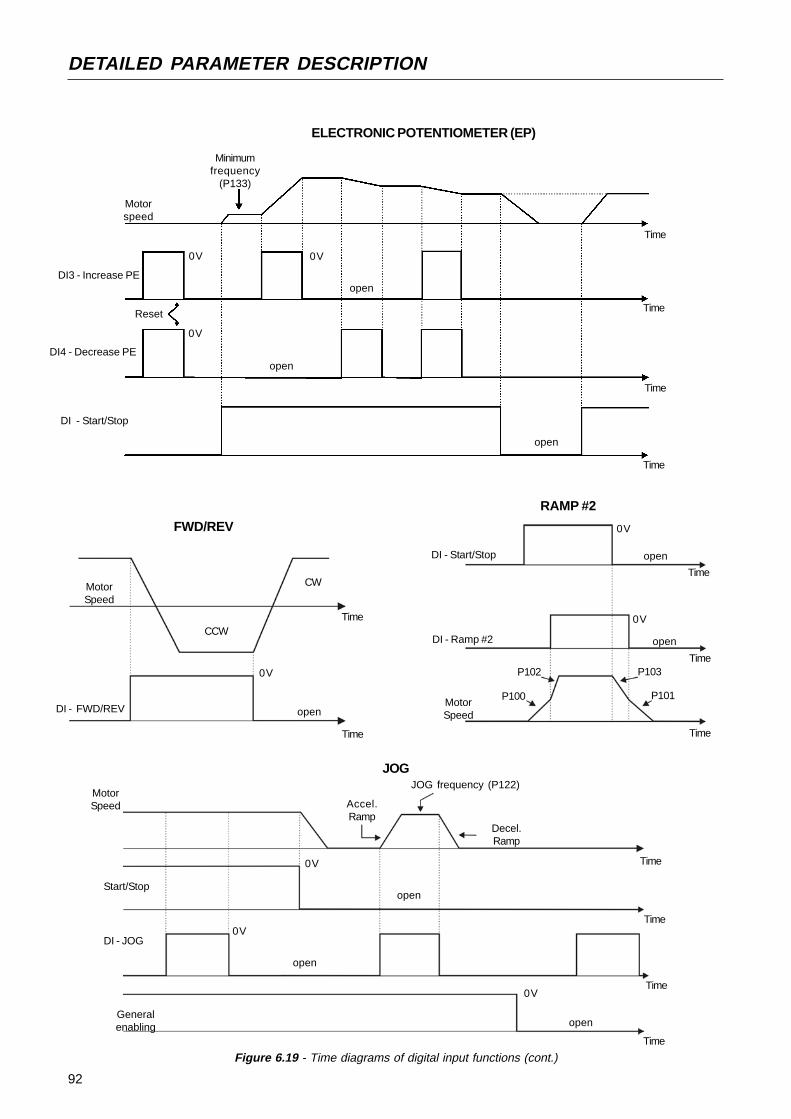
92
DETAILED PARAMETER DESCRIPTION
open
0V
Time
Time
MotorSpeed
DI - FWD/REV
CW
CCW
FWD/REV
open
open
0V
Time
0V
Time
P102
P100
DI - Start/Stop
DI - Ramp #2
RAMP #2
MotorSpeed
P103
P101
Time
Time
Motorspeed
0V
open
DI - Start/Stop
Minimumfrequency
(P133)
Reset
DI4 - Decrease PE
DI3 - Increase PEopen
Time
Time
Time
0V
0V
ELECTRONIC POTENTIOMETER (EP)
open
Figure 6.19 - Time diagrams of digital input functions (cont.)
Time
MotorSpeed
0V
0V
Start/Stop
JOG frequency (P122)
Decel.Ramp
0VDI - JOG
Generalenabling
open
open
open
Accel.Ramp
JOG
Time
Time
Time
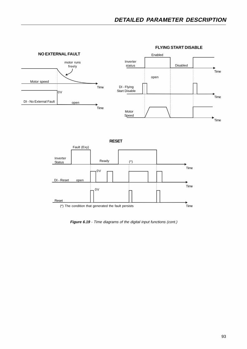
93
DETAILED PARAMETER DESCRIPTION
FLYING START DISABLE
Time
Disabled
open
Enabled
Inverterstatus
DI - FlyingStart Disable
MotorSpeed
open
0V
Time
Time
Motor speed
DI - No External Fault
NO EXTERNAL FAULT
motor runsfreely
Figure 6.19 - Time diagrams of the digital input functions (cont.)
RESETFault (Exy)
Time0V
Time
Time
0V
Ready
Reset
DI - Reset open
InverterStatus (*)
(*) The condition that generated the fault persists
Time
Time

94
DETAILED PARAMETER DESCRIPTION
Range[Factory Setting]
Parameter Unit Description / NotesP277(1) 0...7Relay Output RL1 [ 7 - No fault ]Function -
P279(1) 0...7Relay Output RL2 [ 0 - Fs > Fx ]Function -
Check possible options on table below and details about eachfunction operation on Figure 6.20.
ParameterP279 is onlyavailable in theCFW-08 Plusversion
Figure 6.20 - Details about the operation of the digital relay output fucntions
Fs > Fx
FsFx (P288)
Time
OFFRelay
ON
Is > Ix
IsIx (P290)
Time
OFFRelay
ON
Fs = Fe
Fs
Time
OFFRelay
ON
Fe
Fx (P288)
Time
OFFRelay
ON
Fe > Fx
Run
Stopped motor orrunning by inertia
Time
OFFRelay
ON
Motor running
No Fault
Time
OFF
Relay
Fault State (Exy)Ready/Run State
(1) This parameter can be changed only with the inverter disabled (motor stopped).
ON
Output/Parameter Function
Fs > Fx
Fe > FxFs = FeIs > Ix
Not usedRun (inverter enabled)No fault
P277(RL1)
0
123
4 and 657
P279(RL2)
0
123
4 and 657
95
DETAILED PARAMETER DESCRIPTION
(1) This parameter can be changed only with the inverter disabled (motor stopped).
Range[Factory Setting]
Parameter Unit Description / NotesWhen the definition in the function name is true, the digital outputwill be activated, i.e., the relay coil is energized.When the option 'Not used' has been programmed, the relayoutput(s) will be disabled, i.e., the coil is not energized.CFW-08 Plus has 2 relay outputs (1 NO and 1 NC contact). It ispossible to emulate a reversal contact relay by setting P277 =P279.Definitions of the used symbols in the functions:- Fs = P005 - output frequency (motor)- Fe = reference frequency (ramp input frequency)- Fx = P288 - Fx frequency (user selected frequency point)- Is = P003 - output current (motor)- Ix = P290 - Ix current (user selected current point)
P288 0.00...300.0HzFx Frequency [ 3.00Hz ]
0.01Hz (<100.0Hz);0.1Hz (>99.99Hz)
P290 0...1.5xP295Ix Current [ 1.0xP295 ]
0.01A (<10.0A);0.1A (>9.99A)
Used in the relay output functions Fs>Fx, Fe>Fx and Is>Ix(see P277 and P279).
P295(1) 300...311Rated Inverter [ According to theCurrent (I
nom) rated inverter
current Inom
) ]-
P295
300
301302303
304305306
307308309
310311
Rated InverterCurrent (Inom)
1.0A
1.6A2.6A2.7A
4.0A4.3A6.5A
7.0A7.3A10A
13A16A

96
DETAILED PARAMETER DESCRIPTION
Range[Factory Setting]
Parameter Unit Description / Notes
Thus, P297=4 (5kHz) results in an audible motor noise correspondingto 10kHz. This is due to the used PWM technique .The reduction of the switching frequency also contributes to thereduction of instability and ressonance that may occur in certainapplication conditions, as well as reduces the emission ofelectromagnetic energy by the inveter.The reduction of the switching frequencies also reduces the leakagecurrents to ground, which may avoid the nuisance activation of theground fault protection (E00).The option 15kHz (P297=7) is not available in vector control mode.Use currents according to table below:
P297(1) 4...7Switching Frequency [ 4 - 5kHz ]
-
Defines the switching frequency of the IGBTs in the inveter.
P297
4
567
SwitchingFrequency (fsw)
5kHz
2.5kHz10kHz15kHz
The switching frequency is a comprimise between the motor acousticnoise level and the inverters IGBTs losses. Higher switchingfrequencies cause lower motor acoustic noise level, but increasethe IGBTs losses, increasing the drive components temperature andthus reducing their useful life.The predominant frequency on the motor is twice the switchingfrequency setat P297.
(1) This parameter can be changed only with the inverter disabled (motor stopped).
Inverter Model
CFW080016S2024...CFW080016B2024...CFW080026S2024...
CFW080026B2024...CFW080040S2024...CFW080040B2024...
CFW080070T2024...CFW080073B2024...CFW080100B2024...
CFW080160T2024...CFW080010T3848...CFW080016T3848...
CFW080026T3848...CFW080027T3848...CFW080040T3848...
CFW080043T3848...CFW080065T3848...CFW080100T3848...
CFW080130T3848...CFW080160T3848...
10kHz(P297=6)
1.6A1.6A2.6A
2.6A4.0A4.0A
7.0A7.3A10A
14A1.0A1.6A
2.6A2.7A3.6A
3.9A6.5A8.4A
11A12A
15kHz
(P297=7)1.6A1.6A
2.1A2.6A3.4A
4.0A6.3A7.3A
10A12A1.0A
1.6A2.3A2.7A
2.8A3.0A6.3A
6.4A9A
10A
2,5kHz(P297=5)
1.6A1.6A2.6A
2.6A4.0A4.0A
7.0A7.3A10A
16A1.0A1.6A
2.6A2.7A4.0A
4.3A6.5A10A
13A16A
5kHz(P297=4)
1.6A1.6A2.6A
2.6A4.0A4.0A
7.0A7.3A10A
16A1.0A1.6A
2.6A2.7A4.0A
4.3A6.5A10A
13A16A

97
DETAILED PARAMETER DESCRIPTION
Range[Factory Setting]
Parameter Unit Description / NotesP300 0.0...15.0sDC Braking [ 0.0 ]Time 0.1s
P301 0.00...15.00HzDC Braking [ 1.00Hz ]Start Frequency 0.01Hz
P302 0.0...130%DC Braking [ 0.0% ]Current 0.1%
The DC braking feature provides a motor fast stop via DC currentinjection.The applied DC braking current, that is proportional to the brakingtorque, is set at P302, and is adjusted as a percentage (%)relating to the rated inverter current.The figures below show the DC branking operation at the two possibleconditions: ramp disabling and general disabling.
P301 P300
DEADTIME
open
Time
DI - Start/Stop0V
DC CURRENT INJECTION
Figure 6.21 - DC braking after ramp disabling
P300
open
Time
DEAD TIME
DC CURRENTINJECTION
DI - General Enable
Figure 6.22 - ADC braking after general disabling
Motor SpeedOutput Frequency
0V
Before DC braking starts, there is a "Dead Time" (motor runs freely)required for the motor demagnetization. This time is function of themotor speed at which the DC braking occurs.During the DC braking the LED display flashes .
If the inverter is enabled during the braking process, this processwill be aborted and motor operates normally.DC braking can continue its braking process even after the motorhas stopped. Pay special attention to the dimensioning of the motorthermal protection for cyclic braking of short times.In applications where the motor current is lower than the ratedinverter current, and where the braking torque is not enough forthe braking condition, please contact WEG to optimize thesettings.
Motor SpeedOutput Frequency
98
DETAILED PARAMETER DESCRIPTION
Range[Factory Setting]
Parameter Unit Description / Notes
P304 P133...P134Skip Frequency 2 [ 30.00Hz ]
0.01Hz (<100.0Hz);0.1Hz (99.99Hz)
P306 0.00...25.00HzSkip Band Range [ 0.00 ]
0.01Hz
Figure 6.23 - Skip Frequency" curves
The passage through the skip speed band (2xP306) is madeaccording to the selected acceleration/deceleration rates.This function does not operate properly when two skip frequenciesare overlapped.
P308(1) 1...30Inverter Address (WEG Protocol)
1...247(Modbus-RTU)
[ 1 ]1
Sets the address of the inverter for the serial communication.See item 8.18 and 8.19.The serial interface is an optional inverter accessory.See items 8.9, 8.10 and 8.13 for detailed information.
2 x P306
P30
3
P30
4
P303
P304 2 x P306
FrequencyReference
OutputFrequency
P303 P133...P134Skip Frequency 1 [ 20.00Hz ]
0.01Hz (<100.0Hz);0.1Hz (99.99Hz)
This feature (skip frequencies) prevents the motor from operatingpermamently at speeds where the mechanical system enters intoresonance, causing high vibration or noise levels.The enabling of this function is performed by setting P306 0.00.≠
(1) This parameter can be changed only with the inverter disabled (motor stopped).

99
DETAILED PARAMETER DESCRIPTION
Range[Factory Setting]
Parameter Unit Description / Notes
P311t<2s
tdisabled.>tdead timeEnabled
Disabled
DC link voltage
Undervoltage level(E02)
PWM pulses
Output Voltage
0V
Output Frequency(Motor Speed)0Hz
P310(1) 0...3Flying Start and [ 0 - Inativas ]Ride-Through -
P311 0.1...10.0sVoltage Ramp [ 5.0s ]
0.1s
The parameter P310 selects the active function(s):
P31001
23
Flying StartInactiveActive
ActiveInactive
Ride-ThroughInactiveInactive
ActiveActive
Parameter P311 sets the time required for the motor restart, bothfor flying start function and the ride-through function. In other words, itdefines the time to set the output voltage starting from 0V and up toreaching the rated voltage.Operation of the flying start function:- It allows the motor to start when it is running. This functions acts
only when the inverter is enabled. During the start, the inverter willimpose the speed reference, creating a voltage ramp with timedefined at P311.
- The motor can be started in conventional form, even when theflying start has been selected (P310=1 or 2), adjusting one of thedigital inputs (D13 or D14) to 13 (flying start disable) and driving it(0V) during the motor start.
Ride-Through operation:- Permits the inverter recovery, without disabling by E02
(undervoltage), when a momentary voltage drop in the line occurs.The inverter will be disabled only by E02, if the voltage drop islonger than 2.0s.
- When the ride-through function is enabled (P310=2 or 3) and if avoltage drop in the line occurs, so the link circuit voltage becomeslower than the permitted undervoltage level, the output pulseswill be disabled (motor runs freely) and the inverter waits up to 2sfor the line re-establishment. If the line returns to is normal statuswithin this time, the inverter will enable again the PWMpulses , imposing the frequency reference instantaneously andproviding a voltage ramp with time defined at P311.
- There is a dead time before this voltage ramp is started, requiredfor the motor demagnetization. This time is proportional to theoutput frequency (motor speed).
Figure 6.24 - Ride-Through actuation(1)
This parameter can be changed only with the inverter disabled (motor stopped).

100
DETAILED PARAMETER DESCRIPTION
Range[Factory Setting]
Parameter Unit Description / Notes
If the inverter does not receive any valid message (via serial interface)during the interval programmed at P314, the action set at P313 willbe performed and error E28 is shown on the display.The different actions are:- P313=0 : disables inverter via deceleration ramp;- P313=1 : triggers the general disable command of the inverter;- P313=2 : indicates only E28;- P313=3 : changes the command reference to local mode.If the communication is re-established, E28 switches off and theinverter does not change its status.
Actuation interval of the Serial Watchdog. If the value of P314 isequal to 0, the Serial Watchdog function is disabled. Otherwise, ifthe the inverter does not receive any valid message during thisinterval, it assumes the action that has been programmed at P313.
P313 0...3Serial Interface [ 2 ]Watchdog Action 1
P314 0.0...99.9Serial Interface [ 0.0 – DisableWatchdog Timeout Function]
0
It sets the type of the protocol for the serial communication.The serial interface can be configued for two distinct protocols:WEG and Modbus-RTU.The WEG protocol is described in Item 8.21 and is selectedby setting P312=0.The Modbus-RTU protocol, described in item 8.22 has ninepredefined formats, as shown in table below:
P3121
234
567
89
Rate (bps)9600
96009600
19200
192001920038400
3840038400
Parity-
OddEven
-
OddEven
-
OddEven
P312(1) 0...9Serial Interface [ 0 - WEG Protocol ]
1
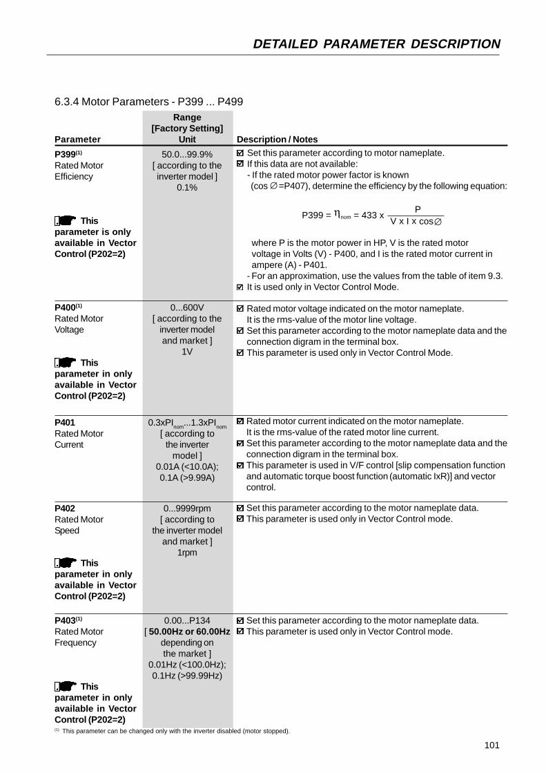
101
DETAILED PARAMETER DESCRIPTION
Range[Factory Setting]
Parameter Unit Description / Notes
P401 0.3xPInom
...1.3xPInom
Rated Motor [ according toCurrent the inverter
model ]0.01A (<10.0A);0.1A (>9.99A)
Rated motor current indicated on the motor nameplate.It is the rms-value of the rated motor line current.Set this parameter according to the motor nameplate data and theconnection digram in the terminal box.This parameter is used in V/F control [slip compensation functionand automatic torque boost function (automatic IxR)] and vectorcontrol.
P402 0...9999rpmRated Motor [ according toSpeed the inverter model
and market ]1rpm
Set this parameter according to the motor nameplate data.This parameter is used only in Vector Control mode.
Thisparameter in onlyavailable in VectorControl (P202=2)
P403(1) 0.00...P134Rated Motor [ 50.00Hz or 60.00HzFrequency depending on
the market ]0.01Hz (<100.0Hz);0.1Hz (>99.99Hz)
Thisparameter in onlyavailable in VectorControl (P202=2)
Set this parameter according to the motor nameplate data.This parameter is used only in Vector Control mode.
6.3.4 Motor Parameters - P399 ... P499
P399(1) 50.0...99.9%Rated Motor [ according to theEfficiency inverter model ]
0.1%
Thisparameter is onlyavailable in VectorControl (P202=2)
Set this parameter according to motor nameplate.If this data are not available:- If the rated motor power factor is known (cos =P407), determine the efficiency by the following equation:
where P is the motor power in HP, V is the rated motorvoltage in Volts (V) - P400, and I is the rated motor current inampere (A) - P401.
- For an approximation, use the values from the table of item 9.3.It is used only in Vector Control Mode.
∅
P399 = η
nom = 433 x
P V x I x cos∅
P400(1) 0...600VRated Motor [ according to theVoltage inverter model
and market ]1V
Thisparameter in onlyavailable in VectorControl (P202=2)
Rated motor voltage indicated on the motor nameplate.It is the rms-value of the motor line voltage.Set this parameter according to the motor nameplate data and theconnection digram in the terminal box.This parameter is used only in Vector Control Mode.
(1) This parameter can be changed only with the inverter disabled (motor stopped).
102
DETAILED PARAMETER DESCRIPTION
Range[Factory Setting]
Parameter Unit Description / Notes
P407(1) 0.50...0.99Rated Motor [ According toPower Factor the inveter model ]
0.01
Set this parameter according to motor nameplate.If this value is not available:- If the rated motor efficiency is known (ηnom=P399), obtain the power factor through the following equation:
PP407 = cos = 433 x
V x I x ηnom
∅
P408(1) 0...1Run Self-Tuning [ 0 ]
-
Thisparameter is shownon the display onlywhen in VectorControl (P202=2)
Through this parameter you can run the self-tuning routine, wherethe stator resistance of the used motor is estimated automaticaalyby the inverter. The motor will not run.By setting P408=1, the Self-Tuning routine is started.During the running of the Self-Tuning routine, the display flashes
.
If the interruption of the Self-Tuning routine is desired, press .If the estimated value of the motor stator resistance is too high forthe applied inverter (examples: motor is not connected or motor istoo small for the inverter) the inveter displays E14. You can only exitfrom this condition by switching off the inverter.
P404(1) 0...15Rated Motor [ According to thePower inverter model ]
-
Thisparameter is onlydisplayed in VectorControl (P202=2)
Set this parameter according to motor nameplate, as shown in tablebelow.
P404
01
234
567
89
10
111213
1415
CV0.16
0.250.330.5
0.751
1.5
234
55.56
7.510
12.5
HP0.16
0.250.330.5
0.751
1.5
234
55.56
7.510
12.5
kW0.12
0.180.250.37
0.550.751.1
1.52.23.0
3.74.04.5
5.57.59.2
Rated Motor power
This parameter is used only in Vector Control mode.
(1) This parameter can be changed only with the inverter disabled (motor stopped).
where P is the motor power in HP, V is the rated line voltage of the motor in volts (V) - P400, and I is the rated motor current in ampère (A) - P401.- For an approximation value, use the values of the table in item 9.3.This parameter is used in V/F control [slip compensation functionand automatic torque boost function (automatic IxR)] and vectorcontrol.
103
DETAILED PARAMETER DESCRIPTION
Range[Factory Setting]
Parameter Unit Description / NotesP409 0.00...9.99Motor Resistance [ According to
the inverter type ]0.01
Thisparameter is shownof the display onlywhen in VectorControl (P202=2)
Value estimated by the Self-Tuning routine.The table in item 9.3 shows the stator resistance for standard, IVpole, 60Hz, 220/380V motors.The value of the stator resistance can also be entered at P409 directly,if this value is known.
NOTE!P409 shall contain the equivalent value of the stator resistanceof one phase, by supposing that the the motor is starconnected (Y).
NOTE!If the value of P409 is to high for the motor, a disabling of theinverter can occur due to overcurrent (E00).

104
DETAILED PARAMETER DESCRIPTION
6.3.5 Special Function Parameters - P500 ... P599
6.3.5.1 PID Introduction CFW-08 is fitted with the PID regulator that can be used for closedloop process control. This function acts as a proportional, integral andderivative regulator, superimposed on the normal inverter speed control.The speed will be changed in order to maintain the process variable(the variable that should be controlled - for instance: water level of acontainer) at the desired value, set in the setpoint.This regulator can, for instance, control the flow in a piping system.The setpoint (flow) can be given by the analog input AI2 or throughP525 (digital setpoint), and the flow feedback signal is given at analoginput AI1.Other application examples: level control, temperature control,dosing control, etc.
Figure 6.25 shows the block diagram of the PID regulator.The feedback signal must be sent to the analog input AI1.The setpoint is the value of the process variable at which the operationis desired. This value is entered as a percentage and is defined by thefollowing equation:
6.3.5.2 Description
setpoint (%) = setpoint (UP) x P234 x 100%
full scale os the used sensor (UP)
where both the setpoint and the full scale value of the sensor are givenby the process unit (°C, bar, etc.).Example: a pressure transducer (sensor) with ouput 4 - 20mAand full scale of 25bar (i.e., 4mA=0bar and 20mA=25bar)and P234=2.00. If the control of 10bar is desired, you should enter thefollowing setpoint:
setpoint (%) = 10 x 2 x 100% = 80%
25
The setpoint can be defined via:- Keypad: digital setpoint, parameter P525.- Analog input AI2 (only available in the CFW-08 Plus): the
percentage value is determined by considering P238, P239 andP240 (see description of these parameters).
The parameter P040 indicates the value of the process variable (feedback)in the scale selected at P528, that is set according to the followingequation:
P528 = full scale value of the used sensor
P234
Example: Consider the data of the example above (pressure sensor of0-25bar and P234=2.00) . P528 must be set to 25/2=12.5.The parameter P040 can be selected as the display default parameterP205=6.

105
DETAILED PARAMETER DESCRIPTION
Set
po
int D
efin
itio
n(r
efe
ren
ce
of
the
proc
ess
varia
ble)
AI2
P2
39
AI2
Sig
na
lP
24
0(A
I2 O
ffset
)AI2
Gai
n
P52
5
2, 3
- A
I2
0-K
ey
P22
1 (L
ocal
) or
P22
2 (R
emot
e)
PID
Set
poin
t(K
ey)
Set
poin
t
PID
Reg
ula
tor
PID
Ram
p
P5
26
Pro
cess
Var
iabl
e F
ilter
P5
28
Pro
cess
Var
iabl
eS
cale
Fac
tor
P2
35
AI1
Sig
na
l
AI1
P2
36
(AI1
Offs
et)A
I1 G
ian
P2
38
P2
34
Fee
db
ack
(mea
sure
men
t of
the
proc
ess
varia
ble)
P5
22
Diff
eren
tial
Reg
ulat
or
P52
0, P
521
PI
Reg
ulad
or(P
ropo
rcio
nal
- In
tegr
al)
P13
4
P13
3
1-R
ever
sal
0-D
irect
PID
Act
ion
Type
DI3
(P26
5=15
)
F*
(see
fig
6.1
)
P5
27
Man
ual
(DI
open
) Fre
quen
cyR
efer
nce
(Spe
ed)
Aut
omat
ic (
DI
clos
ed)
En
ab
ling
Co
mm
an
d
Figure 6.25 - Block diagram of the PID regulator function
0.2s
Fe (s
ee fi
g. 6
.2)

106
DETAILED PARAMETER DESCRIPTION
6.3.5.3 PID Start-Up Guide Please find below a start-up procedure for the PID regulator:Initial Definition1) Process - Definition of the PID action type that the process requires:
direct or reverse. The control action must be direct (P527=0)when it is required to increase the motor speed and so alsoincrement the process variable. Otherwise select reverse(P527=1).Examples:a) Direct: pump driven by inverter and filling a tank where the PID
regulates the tank level. To increase the level height (processvariable) the flow must be increased and consequently also themotor speed must be increased.
b) Reverse: fan driven by an inverter to cool a cooling tower, withthe PID controlling the temperature of this tower. When it isrequired to increase the tower temperature (process variable),the cooling power must be descreased by reducing the motorspeed.
2) Feedback (process variable measurement): The feeback is alwaysrealized via analog input AI1.
Transducer (sensor) to be used for the feedback of the controlvariable: it is recommended to use a sensor with full scalewith at least 1.1 times higher than the largest value of theprocess variable that shall be controlled. Example: If a pressurecontrol at 20bar is desired, select a sensor with a controlcapacity of at least 22bar.Signal type: set P235 and the position of the switch S1 on thecontrol board according to the transducer signal (4-20mA, 0-20mA or 0-10V).
NOTE!When the PID function (P203=1) is set:
The digital input DI3 is automatically set to manual/automatic(P265=15). Thus when DI3 is open, the manual mode is activatedand when DI3 is closed, the PID regulator starts to operate (closedloop control - automatic mode).If the function of this digital input (DI3) is changed, the operation of theinverter will be always in manual mode.If P221 or P222 is equal to 1, 4, 5, 6, 7 or 8 the E24 error mesage willbe displayed. Set P221 and P222 equal to 0 or 2 according to therequirement.
The JOG and the FWD/REV functions are disabled. The inveter enablingand disabling commands are defined by P229 and P230.In the manual mode, the frequency reference is given by F*, as shownin figure 6.1.When the operation mode is changed from manual to automatic, P525is automatically set to the value of P040 (at the instant immediatelybefore the commutation). Thus when the setpoint is defined by P525(P221 or P222=0), the changing from manual to automatic is smooth[there´s not occur abrupt oscillation in the frequency (speed) reference].The analog output can be programmed to indicate the process variable(P040) or the PID setpoint with P251=6 or 4, respectively.Figure 6.26 shows an application example of an inverter controlling aprocess in closed loop (PID regulator).

107
DETAILED PARAMETER DESCRIPTION
Set P234 and P236 according to the variation range of the usedfeedback signal (for more details, see description of the parametersP234 to P240).
Example: suppose the following application:- full scale of the transducer (maximum value at the transducer output)= 25bar (FS=25);- operation range (range of interest) = 0 to 15bar (FO=15).Considering a safety margin of 10%, the measuring range of theprocess variable must be set to: 0 a 16.5bar.Thus: FM=1.1xFS=16.5.Parameter P234 must be set to:
NOTE!In the most cases it is not necessary to set the gain and the offset(P234=1.00 and P236=0.0). Thus the percentage value of the setpoint isequivalent to the percentage value of the full scale of the used sensor.However if the maximum resolution of the analog input AI1 (feedback) isdesired, set P234 and P238 according to comments above.
Setting of the display indication to the process variable measuringunit (P040): set P528 according to the full scale of the usedtransducer (sensor) and defined P234 (see description of parameterP528 below).
3) Reference (setpoint):Local/remote mode.Reference source: set P221 or P222 according to definiton above.
4) Speed limits: set P133 and P134 according to the application.5) Indication:
Display (P040): P040 can be the display default parameter bysetting P205=6.Analog output (AO): it is possible to indicate the process variable(feedback) or the setpoint of the PID regulator at the analog outputby setting P251 to 6 or 9, respectively.
Start-up1) Manual operation (DI3 open):
Display indication (P040): check indication based on externalmeasurement and on the feedback signal (transducer) at AI1.Indication of the process variable at the analog output (AO), ifP251=6.Set the frequency reference (F*) until the desired value of theprocess variable is reached.Only then switch to the automatic mode (inverter will setautomatically P525=P040).
2) Automatic operation: close DI3 and make the dynamic settingof the PID regulator, i.e., adjust the proportional gain (P520), integralgain (P521) and differential gain (P522).
P234 = FS = 25 = 1.52 FM 16.5
As the operation range starts at zero, P236=0, thus a setpoint of100% represents 16.5bar, i.e., the operation range, in percentage,is within: 0 to 90.9%.

108
DETAILED PARAMETER DESCRIPTION
Figure 6.26 - Application example of an inverter with PID regulator
NOTE!The inverter setting must be correct in order to obtain a good performanceof the PID regualtor. Ensure the following settings:
torque boosts (P136 and P137) and slip compensation (P138) in theV/F control (P202=0 ou 1);ensure that the self-tuning has been run, if in vector control (P202=2);acceleration and deceleration ramps (P100...P103);current limitation (P169).
CFW-08
P040Content
Setpoint canbe changedby the keys
X1
1 2 3 4 5 6
Line
1
2S1
off on
1 2 3 4 5 6 7 8 9 10 11 12
DI1
- G
en.e
nabl
e
DI3
- M
anua
l/Aut
oD
I4 -
Sta
r/S
top
AI1
- F
eedb
ack
PressureTransducer
4-20mA
0-25 bar
0-100%(0-25bar)
5k≥ Setpoint via AI2 (availablewith CFW-08 Plus only)P222=2P238=1.00P239=0P240=0.00
Remote mode operation (P220=1)Setpoint via keypad.Inverter Parametrization:P220=1 P520=1.000P222=0 P521=1.000P234=1.00 P522=0.000P235=1 P525=0P238=0.00 P526=0.1sP203=1 P527=0P205=6 P528=25
Process
109
DETAILED PARAMETER DESCRIPTION
Range[Factory Setting]
Parameter Unit Description / NotesP520 0.000...7.999PID Proportional [ 1.000 ]Gain 0.001
P521 0.000...9.999PID Integral [ 1.000 ]Gain 0.001
P522 0.000...9.999PID Differential [ 0.000 ]Gain 0.001
The integral gain can be defined as being the time required to changethe PI regulator output from 0 to P134, that is given, in seconds, bythe equation below:
t = 16 P521.P525
for the following conditions:- P040=P520=0;- DI3 in automatic position.
P525 0.00...100.0%The PID Setpoint [ 0.00 ]
0.01%
Provides the setpoint (reference) of the process via cointrol via the
and keys for the PID regulator, provided that P221=0(local) or P222=0 (remote) has been set to automatic mode. If ithas been set to Manual Mode, the frequency reference is given byP121.If P120=1 (backup active), the value of P525 is maintained at thelast set value (backup), even when the inverter is disabled or tunedoff.
P526 0.00...10.00sProcess Variable [ 0.10s ]Filter 0.01s
It sets the time constant of the Process Variable Filter.It is useful for noise filtering at the analog input AI1(feedback of the process variable).
P527 0...1PID Action [ 0 ]
-
Defines the action type of the PID regulator.
P52701
Action TypeDirect
Reverse
Select it according to the table below:For this the
motor speed
mustIncreaseIncrease
Processvariable
requirementIncreaseDecrease
P527 to beused
0 (Direct)1 (Reverse)
P528 0.00...99.9Process Variable [ 1.00 ]Scale Factor 0.01(<10);
0.1 (>9.99)
Defines the process variables scale. It makes the conversion betweenpercentage value (used internally by the inverter) and the processvariable unit.P528 defines how the process variable at P040 will be shown:P040=value % x P528.Set P528 to:
P528 = full scale of the used sensor (FM) P234
P536 0...1Automatic Setting [ 0 ]of P525 -
It is posible to enable/disable the copy of P040 (PID process variable)in P525 when the changing from manual to automatic mode usingparameter P536, that is described below.
P536
01
Function
Active (copies the value of P040 in P525)Inactive (does not copies the value of P040 in P525)
110
DIAGNOSTICS AND TROUBLESHOOTING
This chapter assists the user to identify and correct possible faults thatcan occur during the CFW-08 operation. Also instructions about requiredperiodical inspections and cleaning procedures are also provided.
When a fault is detected, the inverter is disabled and the fault code isdisplayed on the readout in EXX form, where XX is the actual fault code.
To restart the inverter after a fault has occurred, the inverter must bereset. The reset can be made as follows:
disconnecting and reapplying the AC power (power-on reset);
by pressing the key (manual reset);automatic reset through P206 (auto-reset);via digital input: DI3 (P265 = 10) or DI4 (P266 = 10).
The table below defines each fault code, explains how to reset the faultand shows the possible causes for each fault code.
NOTE!The fault E22, E23, E25, E26, E27 and E28 are related to the serialcommunication and are described in Item 8.18.5.3.
7.1 FAULTS AND POSSIBLECAUSES
FAULT RESET (1) POSSIBLE CAUSES
E00 Power-on Short-circuit between two motor phases.Output Manual (key ) Short-circuit between ground and one of more output phases.
Overcurrent Auto-reset Motor cable capacitance to ground too high, causing peak(between phases DI current at the output (see note on next page)or between phase Inertia of the load too high, or acceleration rampand ground) too short.
P169 set too high.Undue set of P136 and/or P137, when inV/F control (P202=0 or 1).Undue set of P178 and/or P409 when invector control (P202=2).IGBT transistor module is short-circuited
E01 Power supply voltage too high, causing a DC linkDC Link voltage higher than the allowed value:
Overvoltage Ud>410V - 200-240V modelsUd>820V - 380- 480V models
Load inertia too high or deceleration ramp too short.Setting of P151 too high.Load inertia too high and acceleration ramp too short(vector control - P202=2)
E02 Power supply voltage too low, causing a DC linkDC Link voltage higher than the allowed value (read the value
Undervoltage in parameter P004):Ud<200V - 200V - 240V modelsUd<360V - 380V - 480V models
CHAPTER 7

111
DIAGNOSTICS AND TROUBLESHOOTING
Note:(1) In case of E04 Fault due to inverter overtemperature, allow the
inverter to cool down before trying to reset it.In the types 10A/200-240 and 10A/380-480V fitted with internalClass A RFI-filters, the fault E04 can be caused by internal airflowovertemperature. Please check blower installed inside.
FAULT RESET (1) POSSIBLE CAUSES
E04 Power-on Ambient temperature too high (>40oC) and/or outputInverter Manual (key ) current too high.
Overtemperature Auto-reset Blower locked or defective. DI
E05 P156 set too low for the motor that is being used. Motor/Inverter Motor is under an actual overload condition.
Overload Ixt Function
E06 Ani DI (DI3 and/or DI4) programmed for external fault External Fault detection is open (not connected to GND - XC1).
E08 Electrical noise.CPU Error
(Watchdog)
E09 Contact WEG Memory with corrupted values.Program Memory (refer to section 7.3)Error (Checksum)
E10 Power-on Defective contact in the HMI-CFW08-RS cable.Keypad Manual (key ) Electrical noise in the installation
Error Auto-reset (electromagnetic interference). DI
E14 Power-on Motor is not connected to the inverter output.Self-Tuning Manual (key ) Wrong motor connection (wrong voltage, lack of one
Fault phase).The used motor is too small for the inverter(P401<0.3 x P295). Use V/Fcontrol.The value of P409 (stator resistance) is too high for the usedinverter.
E24 It is automatically reset Incompatible parameters were programmed
Programming when the incompatible Refer to table 5.1.error parameters are changed
E31 It is reset automatically Keypad cable misconnected.Keypad (HMI) when the communication Electrical noise in the installation (electromagneticConnection Fault between inverter and the interference).
keypad is reestablished.
E41 Contact WEG Inverter power circuit is defective.Self- Diagnosis (refer to section 7.3)
Fault
NOTE!Long motor cables (longer than 150ft (50 m)) can generate excessivecapacitance to ground. This can cause nuisance ground fault trip andconsequently disabling by E00 fault immediately after the inverter hasbeen enabled. Solution:
Reduce the switching frequency (P297).Connect a load reactor in series with the motor supply line.Refer to Section 8.16.

112
DIAGNOSTICS AND TROUBLESHOOTING
NOTE!The faults act as follows:
E00 ... E06: switches off the relay that has been programmed to “nofault”, disables the PWM pulses, displays the fault code on the displayand the “ERROR” LED flashes.Some data are saved on the EEPROM memory: keypad referenceand EP (electronic potentiometer) (when the function “backupof the references” at P120 has been enabled), the occurred fault number,the status of the integrator of the IxT function (overcurrent).
E24: Indicates the fault code on the LED display.
E31: Inverter proceeds to operate normally, but it does not acceptthe keypad commands; the fault code is indicated on the LED display.
E41: does not allow inverter operation (it is not possible to enable theinverter); the fault code is indicated on the LED display and on the“ERROR” LED.
Indication on the Inverter Status LEDs:
7.2 TROUBLESHOOTING
PROBLEM POINT TO BE CORRECTIVE ACTION CHECKED
Motor does not run Incorrect wiring 1.Check the power and the control connections. For example,the digital inputs DIx programmed for Start/Stop or General Enableor No External Fault must be connected to GND (pin 5 of thecontrol connector XC1).
Analog reference 1.Check if the external signal is properly connected.(if used) 2.Check the status of the speed potentiometer (if used).
Incorrect Programming 1.Check if the parameters are properly programmed for theapplication.
Fault 1.Check if the inverter has not been disabled due to detected faultcondition (refer to Table above).
Motor Stall 1.Reduce the motor load.2.Increase P169 or P136/P137.
(Flashing)
Inverter is powered up and is ready
A fault has been detected.The Error LED flashes, indicating thenumber of the fault code.Example: E04
0,2s 0,6s
PowerLED Error LED Description

113
DIAGNOSTICS AND TROUBLESHOOTING
PROBLEM POINT TO BE CORRECTIVE ACTION CHECKED
Motor speed Loose connections 1.Disable the inverter, switch OFF the power supply and tighten allvaries connections.
(oscillates) Defective speed 1.Replace the defective speed potentiometer.potentiometer
Variation of the external 1.Identify the cause of the variation.analog reference
Motor speed Programming error 1.Check if the contents of P133 (minimum frequency)too high or (reference limits) and P134 (maximum frequency) are according to the motortoo low application.
Signal of the 1.Check the control signal level of the reference.Reference Control 2.Check the programming (gains and offset) at P234 to P240.
Motor nameplate 1.Check if the used motor meets the application requirements.data
Display OFF Keypad connection 1.Check the keypad connections to the inverter.
Power supply 1.The power supply must be within the following ranges:200-240V models: - Min: 170V
- Max: 264V380-480V models: - Min: 323V
- Max: 528V
NOTE!When contacting WEG for services, please have the following data onhand:
Inverter model;serial number, manufacturing date and hardware revision, as indicatedon the inverter nameplate (refer to section 2.4);Software version (refer to section 2.2);information about the application and inverter programming.
7.3 CONTACTING WEG
7.4 PREVENTIVEMAINTENANCE
DANGER!Always disconnect the power supply voltage before touching anycomponent of the inverter.
Even after switching OFF the inverter, high voltages may be present.Wait 10 minutes to allow complete discharge of the power capacitors.Always connect the equipment frame to a suitable ground (PE) point.

114
DIAGNOSTICS AND TROUBLESHOOTING
ATTENTION!
Electronic boards have components sensitive to electrostatic discharges.Never touch the components or connectors directly. If this is unavoidable,first touch the metallic frame or use a suitable ground strap.
Never apply a high voltage test on the inverter!If this is necessary, contact WEG.
To avoid operation problems caused by harsh ambient conditions, suchas high temperature, moisture, dirt, vibration or premature ageing of thecomponents, periodic inspections of the inverter and installations arerecommended.
COMPONENTS PROBLEMS CORRECTIVE ACTIONS
Terminal blocks Loose screws Tighten themLoose connectors
Blowers (1) / Cooling Blowers are dirty Clean themsystem Abnormal acoustic noise Replace the blowers
Blower is not runningAbnormal vibrationDust in the air filters Clean or replace them
Printed circuit boards Dust, oil or moisture accumulation Clean them and/or replace themSmell Replace them
Table 7.1 - Periodic inspection after start-upNotes:(1) It is recommended to replace the blowers after 40,000 hours of operation.
ATTENTION!
If the inverter is stored for long periods, we recommend to power it uponce a year during 1 hour. For all models (200-240V or 380-480V) applysupply voltage of approx. 220V, three-phase or single phase input, 50 or60 Hz, without connecting motor at output. After this energization, wait 24hours before installing it.
7.4.1 Cleaning Instructions When required to clean the inverter, flow the instructions below:a) Cooling System:
Remove AC power from the inverter and wait 10 minutes.Remove all dust from ventilation openings by using a plastic brush ora soft cloth.Remove dust accumulated on the heatsink fins and from the blowerblades with compressed air.
b) Electronic Boards:Remove AC power from the inverter and wait 10 minutes.Disconnect the inverter cables, ensuring that they are marked carefullyto facilitate later reconnection.Remove the keypad and the plastic cover (refer to section 3).Remove all dust from the printed circuit boards by using an anti-staticsoft brush and/or remove it with an ionized compressed air gun; (forexample: Charges Burtes Ion Gun (non nuclear) Ref. A6030-6 DESCO).

115
CHAPTER 8
CFW-08 OPTIONS AND ACCESSORIES
This Chapter describes the optional devices that can be used internal orexternal with the CFW-08 . Table below shows a list of existing optionaldevices and the types to which they are applied. Are also given informationabout the optional devices and their application.
Name
HMI-CFW08-P
TCL-CFW08
HMI-CFW08-RP
MIP-CFW08-RP
HMI-CFW08-RS
MIS-CFW08-RS
CAB-RS-1CAB-RS-2CAB-RS-3
CAB-RS-5CAB-RS-7.5CAB-RS-10
CAB-RP-1CAB-RP-2CAB-RP-3
CAB-RP-5CAB-RP-7.5CAB-RP-10
KCS-CFW08
KSD-CFW08
KMD-CFW08-M1
KFIX-CFW08-M1
KFIX-CFW08-M2
KN1-CFW08-M1
KN1-CFW08-M2
MIW-02
Function
Parallel keypad (HMI)Over to be inserted in the place of the parallel HMI (when it ismounted in the inverter or it is remote - kit KMR-CFW08-P).
HMI parallel keypad. For remote use with MIP-CFW08-RPinterface and CAB-CFW08-RP (up to 10m).Interface for the external parallel keypad (remote) HMI-CFW08-RP
HMI serial keypad. For remote use with MIS-CFW08-RSinterface and CAB-RS (up to 10m). Copy Function.Interface for the external serial keypad (remote) HMI-CFW08-RS
Cable for the remote serial keypad - cable: 1mCable for the remote serial keypad - cable: 2mCable for the remote serial keypad - cable: 3m
Cable for the remote serial keypad - cable: 5mCable for the remote serial keypad - cable: 7.5mCable for the remote serial keypad - cable: 10m
Cable for the remote parallel keypad - cable: 1mCable for the remote parallel keypad - cable: 2mCable for the remote parallel keypad - cable: 3m
Cable for the remote parallel keypad - cable: 5mCable for the remote parallel keypad - cable: 7.5mCable for the remote parallel keypad - cable: 10m
RS-232 communication interface (PC, PLC, etc).RS-485 possible when module MIW-02 is used.RS-232 PC Communication kit : interface RS-232 (KCS-CFW08),
cable RJ-6 to DB9, 3m long, software “SUPERDRIVE”.
Rail Kit -DIN EN 50.022
Fix Kit -M1
Fix Kit - M2
Kit NEMA 1/IP20 for the connection of the metallic conduit -M1
Kit NEMA1/IP20 for the connection of the metallic conduit -M2
RS-232 to RS-485 conversion module (external).CFW-08 must be fitted with KCS-CFW08 module.
Models to whichare applied
All
1.6-2.6-4.0-7.0A/200-240V
1.0-1.6-2.6-4.0A/380-480V
1.6-2.6-4.0-7.0A/
200-240V1.0-1.6-2.6-4.0A/
380-480V
7.3-10-16A/200-240V
2.7-4.3-6.5-10A/
380-480V1.6-2.6-4.0-7.0A/
200-240V
1.0-1.6-2.6-4.0A/380-480V
7.3-10-16A/
200-240V2.7-4.3-6.5-10A/
380-480V
All
WEG ItemNumber
417100868
417100881
417100991
417100990
417100992
417100993
0307.78270307.78280307.7829
0307.78300307.78310307.7832
0307.77110307.77120307.7713
0307.78330307.78340307.7835
417100882
417100875
417100879
417100994
417100995
417100877
417100880
417100543

116
CFW-08 OPTIONS AND ACCESSORIES
Name
FIL1
FIL2
FIL4
FEX1-CFW08
FEX2-CFW08
FS6007-16-06
FN3258-7-45
FS6007-25-08
FS6007-36-08
FN3258-16-45
FN3258-30-47
TOR1-CFW08
TOR2-CFW08
Function
Internal class A suppressor filter RFI - A - 7.3A/200-240VInternal class A suppressor filter RFI- A - 2.7-4.3-6.5-10A/380-480V
Internal class A suppressor filter - RFI - 13-16A/380-480V
10A/200-240V class A RFI filter - footprint
5A/380-480V class A RFI filter - footprint
External class B suppressor filter - RFI - 1.6-2.6-4.0A/
200-240V
External class B suppressor filter - RFI - 1.0-1.6-2.6-2.7-4.0-4.3A/380-480V
External class B suppressor filter -RFI - 7.3A/200-240V single-phase
External class B suppressor filter -RFI - 10A/200-240V single-phase
External class B suppressor filter - RFI - 6.5-10-13A/380-480V
External class B suppressor filter - RFI - 16A/380-480V
CM choke toroid #1 (Thornton NT35/22/22-4100-IP12R) and
plastic clamp
CM choke toroid #2 (Thornton NT52/32/20-4400-IP12E)
Models to whichare applied
7.3-10A/200-240V2.7-4.3-6.5-10A/
380-480V
13-16A/380-480V1.6-2.6-4.0A/
200-240V
1.0-1.6-2.6-4.0A/380-480V
1.6-2.6-4.0A/
200-240V1.0-1.6-2.6-2.7-
4.0-4.3A/
380-480V
7.3A/200-240V
10A/200-240V
6.5-10-13A/
380-480V,7A/200-240V,
7.3-10A/200-240V
three-phase16A/200-240V;16A/380-480V
2.7-4.3-6.5-10A/
380-480V2.7-4.3-6.5-10-
13-16A/380-480V
WEGItem Number
4151.2661
4151.0994
4151.2148
41718238
41718239
0208.2072
0208.2075
0208.2073
0208.2074
0208.2076
0208.2077
417100895
417100896
Table 8.1 - Available Optional Devices for the CFW-08
8.1 HMI-CFW08-P Parallel keypad (HMI): is the keypad that is mounted at the front side ofthe inverter.
Figure 8.1 - Dimensions of the parallel HMI - HMI-CFW08-P
57
4321
13

117
CFW-08 OPTIONS AND ACCESSORIES
1. Unlock the keypad by using a screwdriver as shown above.2. Remove the keypad by pulling on the lateral sides.
(b) Removing
Figure 8.2 - Instructions for HMI-CFW-08-P insertion and removing
8.2 TCL-CFW08 Dummy panel to be inserted in the place of the parallel keypad (HMI-CFW08-P).
Figure 8.3 - Dimensions of the dummy panel TCL-CFW08 for the parallel HMI
43
57
13
1. Place the keypad as shown above.2. Press it.
(a) Insertion
8.1.1 Instruction for Insertionand Removing of theHMI-CFW08-P
8.3 HMI-CFW08-RP External parallel keypad: this keypad is mounted externally to theinverter and can be used in the following cases:
Applications that require a remote keypad (up to 10m / 394in);Instalation of a keypad directly on the panel door (0,12in);For a better visualization on the display and to facilitale the keyoperation, when compared with the parallel keypad (HMI-CFW08-P).
The external parallel keypad (HMI-CFW08-RP) must be used with theMIP-CFW08-RP interface and CAB-RP-X cable.

118
CFW-08 OPTIONS AND ACCESSORIES
Figure 8.4 - Dimensions of the HMI-CFW08-RP
8.3.1 HMI-CFW08-RPInstallation
The HMI-CFW08-RP can be installed directly on the panel door (0,12in),as shown in the figures below:
Figure 8.5 - Installation of the HMI-CFW08-RP
8.4 MIP-CFW08-RP Isolation interface: Isolation interface installed in the inverter instead ofthe standard keypad only when the remote parallel keypad (HMI-CFW08-RP) is used.The procedures for insertion and removing of the MIP-CFW08-RP aresimilar to those shown in figure 8.13 for the KCS-CFW08 module.
5898
15.9
36.3
52mm(2.05in)
92m
m(3
.62i
n)
Max. 3mm
(0.12in)
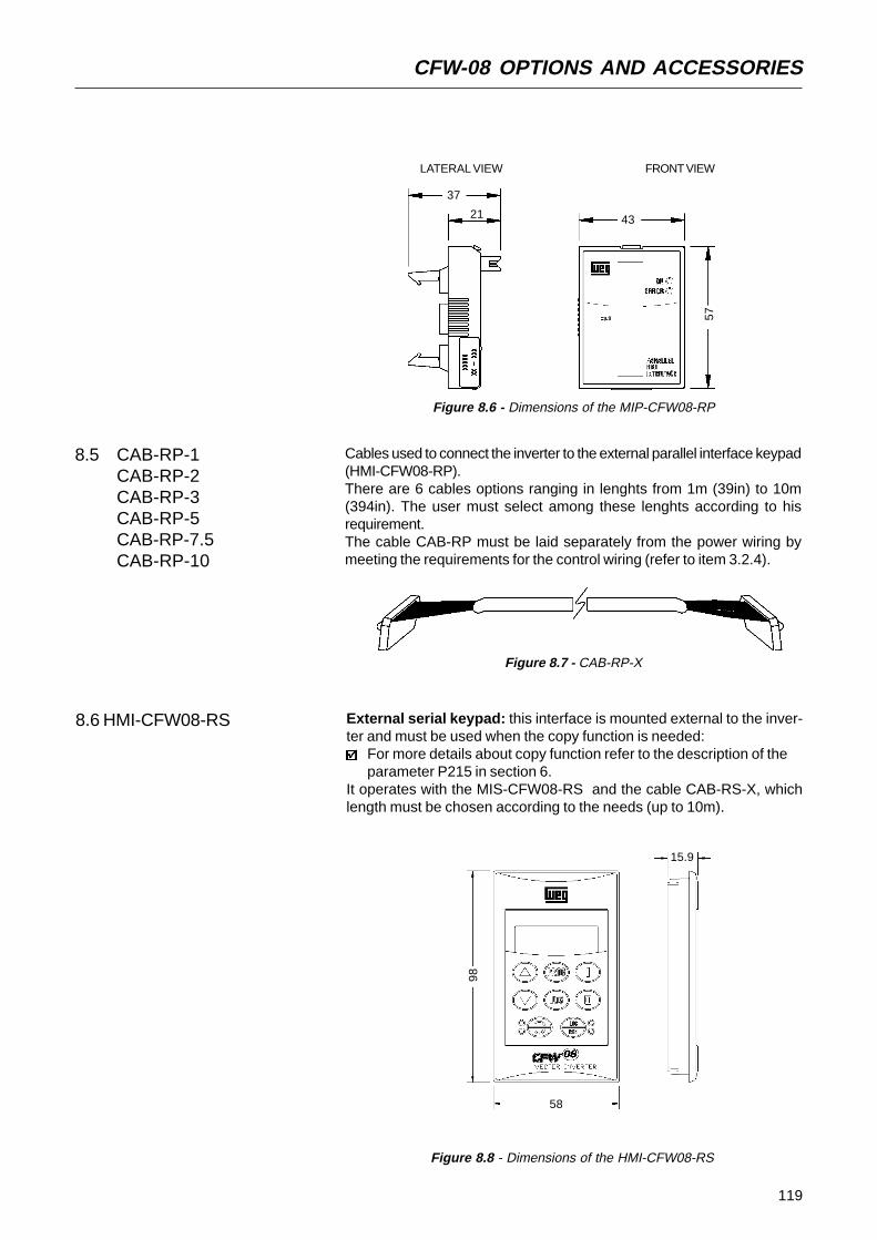
119
CFW-08 OPTIONS AND ACCESSORIES
8.5 CAB-RP-1CAB-RP-2CAB-RP-3CAB-RP-5CAB-RP-7.5CAB-RP-10
Cables used to connect the inverter to the external parallel interface keypad(HMI-CFW08-RP).There are 6 cables options ranging in lenghts from 1m (39in) to 10m(394in). The user must select among these lenghts according to hisrequirement.The cable CAB-RP must be laid separately from the power wiring bymeeting the requirements for the control wiring (refer to item 3.2.4).
Figure 8.7 - CAB-RP-X
8.6 HMI-CFW08-RS
Figure 8.6 - Dimensions of the MIP-CFW08-RP
4321
37
57
LATERAL VIEW FRONT VIEW
Figure 8.8 - Dimensions of the HMI-CFW08-RS
External serial keypad: this interface is mounted external to the inver-ter and must be used when the copy function is needed:
For more details about copy function refer to the description of theparameter P215 in section 6.
It operates with the MIS-CFW08-RS and the cable CAB-RS-X, whichlength must be chosen according to the needs (up to 10m).
58
15.9
98

120
CFW-08 OPTIONS AND ACCESSORIES
8.5 CAB-HMI08-RP-1CAB-HMI08-RP-2CAB-HMI08-RP-3CAB-HMI08-RP-5CAB-HMI08-RP-7.5CAB-HMI08-RP-10
Cables used to connect the inverter to the external parallel interface keypad(HMI-CFW08-RP).There are 6 cables options ranging in lenghts from 1m (39in) to 10m(394in). The user must select among these lenghts according to hisrequirement.The cable CAB-HMI08-RP must be laid separately from the power wiringby meeting the requirements for the control wiring (refer to item 3.2.4).
Figure 8.7 - CAB-CFW08-RP
8.6 HMI-CFW08-RS
Figure 8.6 - Dimensions of the MIP-CFW08-RP
4321
37
57
LATERAL VIEW FRONT VIEW
Figure 8.8 - Dimensions of the HMI-CFW08-RS
External serial keypad: this interface is mounted external to the inver-ter and must be used when the copy function is needed:
For more details about copy function refer to the description of theparameter P215 in section 6.
It operates with the MIS-CFW08-RS and the cable CAB-RS-X, whichlength must be chosen according to the needs (up to 10m).
58
15.9
98

121
CFW-08 OPTIONS AND ACCESSORIES
8.6.3 Keypad Copy Function The HMI-CFW08-RS keypad still has an additional function: the keypadcopy function.This function is useful when one wants to copy the settingsof one inverter (source inverter) to another (target inverter) or one needs toprogram several inverters with the same settings.This is done as follows: the parameters of the source inverter are copiedto a non-volatile memory of the HMI-CFW08-RS keypad , and then fromthis keypad to another inverter (“target inverter"). The keypad copy functionis controlled by the paramater P215.For further information on this function refer to section 6.
Function via HMI-CFW08-RS
Frequency referenceCommands (*)Forward/Reverse Selection
Loca/RemoteSelection
Local Mode
P221 = 0P229 = 2
Remote Mode
P222 = 0P230 = 2
P231 = 2P220 = 5 (default local) or
P220 = 6 (default remote)
Note:Factory setting
(*) Except the forward/reverse selection that also depends on the paremater P231.Table 8.2 - Parameter setting for HMI-CFW08-RS operation
8.7 MIS-CFW08-RS Serial interface used exclusively for HMI-CFW08-RS keypad connectionto inverter.The procedures for insertion and removing of the MIS-CFW08-RS are si-milar to those shown in Figure 8.13 for the KCS-CFW08 module.
Figure 8.11 - Dimensions of the MIS-CFW08 serial communication modulefot the extern serial HMI
57
4321
20
Cables used to connect the inverter to the external serial interface keypad(HMI-CFW08-RS). There are 6 cable options ranging in lengths from 1mto 10 m. The user must select among these lengths according to hisrequirement.The cable CAB-RS must be laid separately from the power wiring bymeeting the requirements for the control wiring (refer to item 3.2.4).
8.8 CAB-RS-1CAB-RS-2CAB-RS-3CAB-RS-5CAB-RS-7.5CAB-RS-10
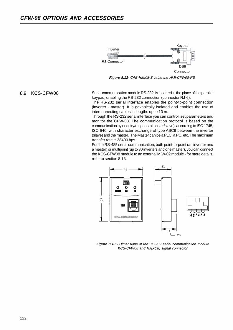
122
CFW-08 OPTIONS AND ACCESSORIES
8.9 KCS-CFW08 Serial communication module RS-232: is inserted in the place of the parallelkeypad, enabling the RS-232 connection (connector RJ-6).The RS-232 serial interface enables the point-to-point connection(inverter - master). It is gavanically isolated and enables the use ofinterconnecting cables in lengths up to 10 m.Through the RS-232 serial interface you can control, set parameters andmonitor the CFW-08. The communication protocol is based on thecommunication by enquiry/response (master/slave), according to ISO 1745,ISO 646, with character exchange of type ASCII between the inverter(slave) and the master. The Master can be a PLC, a PC, etc. The maximumtransfer rate is 38400 bps.For the RS-485 serial communication, both point-to-point (an inverter anda master) or multipoint (up to 30 inverters and one master), you can connectthe KCS-CFW08 module to an external MIW-02 module - for more details,refer to section 8.13.
Figure 8.13 - Dimensions of the RS-232 serial communication moduleKCS-CFW08 and RJ(XC8) signal connector
57
4321
20
Figure 8.12- CAB-HMI08-S cable the HMI-CFW08-RS
Inverter
RJ Connector
Keypad
DB9Connector
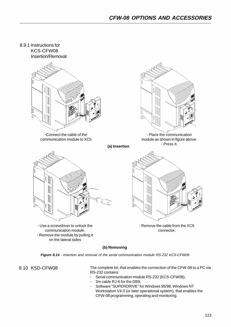
123
CFW-08 OPTIONS AND ACCESSORIES
8.9.1 Instructions forKCS-CFW08Insertion/Removal
-Connect the cable of thecommunication module to XC5
- Place the communicationmodule as shown in figure above.
- Press it.(a) Insertion
- Use a screwdriver to unlock thecommunication module.
- Remove the module by pulling iton the lateral sides
(b) Removing
- Remove the cable from the XC5connector.
Figure 8.14 - Insertion and removal of the serial communication module RS-232 KCS-CFW08
8.10 KSD-CFW08 The complete kit, that enables the connection of the CFW-08 to a PC viaRS-232 contains:- Serial communication module RS-232 (KCS-CFW08);- 3m cable RJ-6 for the DB9;- Software “SUPERDRIVE” for Windows 95/98, Windows NT
Workstation V4.0 (or later operational system), that enables theCFW-08 programming, operating and monitoring.

124
CFW-08 OPTIONS AND ACCESSORIES
To install the RS-232 communication kit on the PC, proceed as follows:- Remove the parallel keypad (HMI-CFW08-P) from the inverter.- Install the serial communication module RS-232 (KCS-CFW08) in the
place of the keypad.- Install the software “SUPERDRIVE” in the PC.- Connect the inverter to the PC through the cable.- Follow the instruction given by the “SUPERDRIVE”.
8.11 KMD-CFW08-M1 This device must be used when the installation of the inverter on 35mmrail, according to DIN EN 50.022, is desiredOnly available for the models: 1.6-2.6-4.0-7.0A/ 200-240V and
1.0-1.6-2.6-4.0A/380-480V
Figure 8.15 - Inverter with DIN rail kit (KMD-CFW-08-M1)
Section A-A
Front View Section B-
12
75
129
140
464 B
B
A'A
9

125
CFW-08 OPTIONS AND ACCESSORIES
This kit must be used when a better access to the screw hole of theinverter is needed. Models that used this kit:KFIX-CFW08-M11,6 - 2,6 - 4,0 - 7,0A/200-240V; 1,0 - 1,6 - 2,6 - 4,0A/380-480V
KFIX-CFW08-M27,3 - 10 - 16A/200-240V; 2,7 - 4,3 - 6,5 - 10A/380-480V
8.12 KFIX-CFW08-M1KFIX-CFW08-M2
Figura 8.16 - Dimensions of the inverter with the kit(KFIX-CFW08-MX)
Dimensions (mm)A B C D E50 75 8 180 19080 115 8 228 238
KFIX-CFW08-M1KFIX-CFW08-M2

126
CFW-08 OPTIONS AND ACCESSORIES
(a) KN1-CFW08-M1 (b) KN1-CFW08-M2
Figure 8.17 - Dimensions of the NEMA1/IP20 kits
68
75 89
106
115 86
(a) Inverters 1.6-2.6- 4.0-7.0/220-240V;1.0-1.6-2.6-4.0/380-480V with KN1-CFW08-M1
(b) Inverters 7.3-10-16A/200-240V;2.7-4.3-6.5-10A/380-480V with KN1-CFW08-M2
Figure 8.18 - External dimensions of the inverter with NEMA1/IP20 kit
External module for conversion from RS-232 to RS-485: it allows theconnection of the CFW-08, when fitted with RS-232 serial module (KCS-CFW08) to a standard RS-485 line.So the inverter can participate in a multipoint line up to 1000m without theuse of transducers. For more details about this connection, see item8.18.7 and the MIW-02 USER MANUAL. The communication protocolssupported by this serial interface are detailed in items 8.18 WEG and 8.19RTU-Modbus.
8.14 MIW-02
Bottom View
Front View Lateral Right View
Front View
Bottom View
Lateral Left View
68
38
∅18
141
172
10
45
22
115 150
200
150
89
234
This kit is used, when a NEMA 1/IP20 degree of protection is desired forthe inverter or when for the inverter wiring metallic conduits are desired.Models that use this kit:KN1-CFW08-M1:1.6-2.6- 4.0-7.0/220-240V; 1.0-1.6-2.6-4.0/380-480VKN1-CFW08-M2:7.3-10-16A/200-240V; 2.7-4.3-6.5-10A/380-480VModels 13 and 16A/380-480V have Nema 1/IP20 degree of protection inthe standard version.
8.13 KN1-CFW08-M1KN1-CFW08-M2

127
CFW-08 OPTIONS AND ACCESSORIES
Figure 8.19 - Connection of the CFW-08 to a standard RS-485communication network
CFW-08
RS-485
RS-232
MIW-02
POWSER
WEG networkRS-485
8.15 RFI FILTER The installation of frequency inverters requires some care in order to preventelectromagnetic interferences (EMI).This electromagnetic interference may disturb the operation of the inver-ter itself or other devices, such as electronic sensors, PLCs, transducers,radio equipment, etc. installed in the proximity.To avoid these troubles, follow the installation instructions contained inthis Manual.In this case, avoid the installation of electromagnetic noise generatingcircuits, such as power cables, motors, etc. near to signal or controlcables.Care should also be taken with the radiated interference, by shielding thecables and the circuits that tend to emit electromagnetic waves and cancause interference.The electromagnetic interference can also be transmitted through powersupply line. This type of interference is minimized in the most cases bycapacitive filters which are already installed inside the CFW-08.However, when inverters are installed in residential areas, the installationof additional filter may be required.These filters may be installed internally (on some types) or externally.As defined in standards, the Class B filter has more attenuation capacitythan the Class A filter , thus being more suitable for residential areas.Section 8.1 lists the available RFI filters with the respective inverter models.The inverters with internal Class A filters have the same external dimensionsas the inverters without filter.The external Class B filters must be installed between the power supplyline and the inverter input, as shown in Figure 8.18 below.Instructions for the RFI filter installation:
Install the inverter and the filter on a metallic grounded plate as near toeach other as possible and ensure a good electrical contact betweenthe grounded plate and the inverter and filter frames.For motor connection use a shielded cable or individual cables insidea grounded metallic conduit.

128
CFW-08 OPTIONS AND ACCESSORIES
PowerSupply
Ground
Filter
CFW-08
Driving Panel
Conduit orShielded Cable
Motor
Motor Ground(frame)
PE PE
Figure 8.20 - Connection of the external RFI filter - Class B
8.16 LINE REACTOR Due to the input circuit characteristic, common to the most invertersavailable on the market, consisting of a diode rectifier and a capacitorbank, the input current (drained from the power supply line) of inverters isa non sinusoidal waveform and contains harmonics of the fundamentalfrequency (frequency of the power supply - 60 or 50Hz).These harmonic currents circulate through the power supply line andcause harmonic voltage drops which distort the power supply voltage ofthe inverter and other loads connected to this line. These harmonic currentsand voltage distortions may increase the electrical losses in theinstallation, overheating the components (cables, transformers, capacitorbanks, motors, etc.), as well as lowering the power factor.The harmonic input currents depend on the impedance values that arepresent in the rectifier input/output circuit.The installation of a line reactor reduces the harmonic content of theinput current, providing the following advantages:
increasing the input power factor;reduction of the RMS input current;reduction of the power supply voltage distortion;increasing the life of the DC link capacitors.reduction of the overvoltage transients that may occur in the powersupply line.
8.16.1 Application Criteria In a general manner, the CFW-08 series inverters can be connecteddirectly to the power supply line without line reactors. But in this case,ensure the following:
To ensure the inverter expected life, a minimum line impedancethat introduces a voltage drop as shown in table 8.3, as a function ofthe motor load, is recommended. If the line impedance (transformers+ wirings) is lower than these values, it is recommended to use linereactor(s).When it is necessary to add a line reactor to the system, it isrecommended to size it considering a 2 to 4% voltage drop (fornominal output current). This pratice is results in a compromise betweenmotor voltage drop, power factor improvement and harmonic currentdistortion reduction.
Install it as close aspossible to the
inverter
NOTE!For installations that must meet the European standards refer to item 3.3.
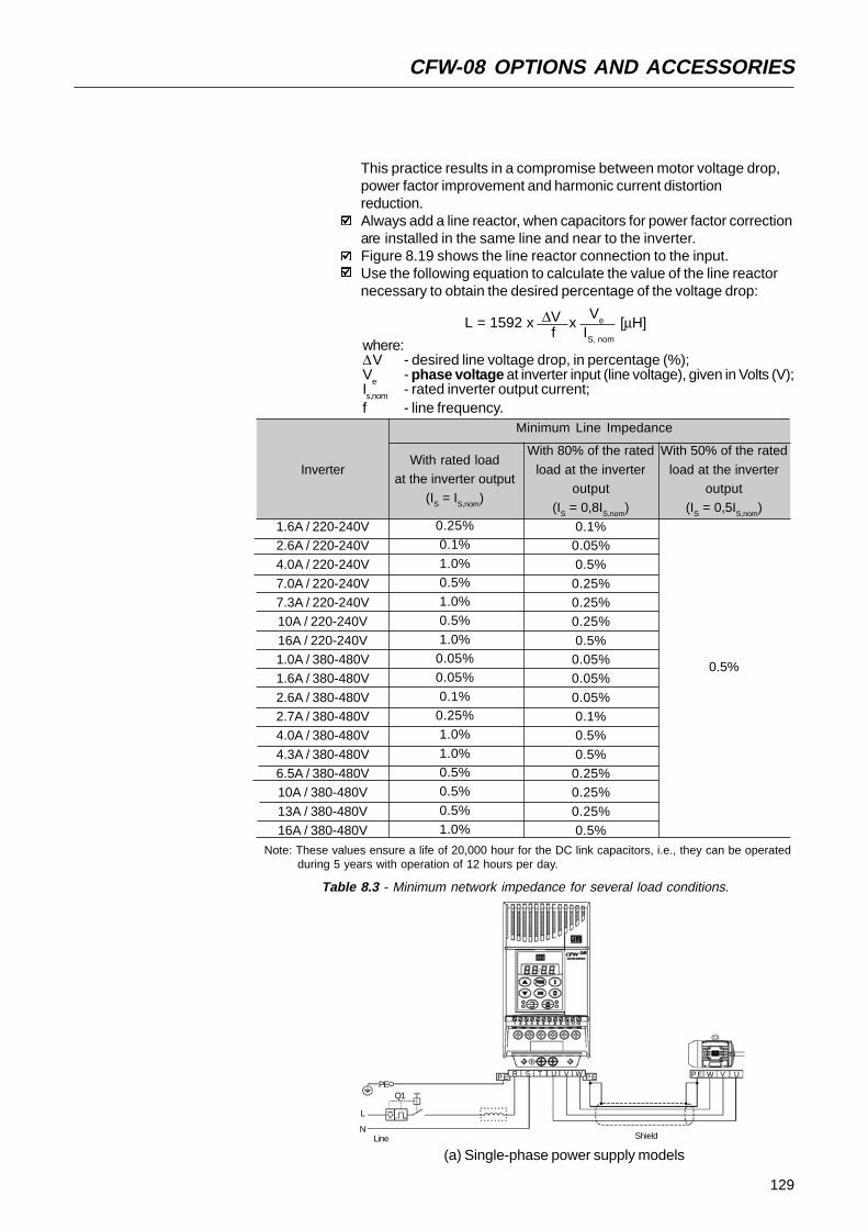
129
CFW-08 OPTIONS AND ACCESSORIES
[µH]L = 1592 x ∆V x
Ve
f IS, nomwhere:
∆V - desired line voltage drop, in percentage (%);V
e- phase voltage at inverter input (line voltage), given in Volts (V);
Is,nom
- rated inverter output current;f - line frequency.
L
PEP ER UVWP E
Q1
S T U V W P E
This practice results in a compromise between motor voltage drop,power factor improvement and harmonic current distortionreduction.Always add a line reactor, when capacitors for power factor correctionare installed in the same line and near to the inverter.Figure 8.19 shows the line reactor connection to the input.Use the following equation to calculate the value of the line reactornecessary to obtain the desired percentage of the voltage drop:
(a) Single-phase power supply modelsLine
NShield
0.5%
With rated loadat the inverter output
(IS = IS,nom)
0.25%0.1%
1.0%0.5%1.0%0.5%
1.0%0.05%0.05%
0.1%0.25%1.0%
1.0%0.5%0.5%
0.5%1.0%
With 80% of the rated
load at the inverteroutput
(IS = 0,8IS,nom)
0.1%0.05%0.5%
0.25%0.25%0.25%
0.5%0.05%0.05%
0.05%0.1%0.5%
0.5%0.25%0.25%
0.25%0.5%
With 50% of the rated
load at the inverteroutput
(IS = 0,5IS,nom)
Minimum Line Impedance
Note: These values ensure a life of 20,000 hour for the DC link capacitors, i.e., they can be operated during 5 years with operation of 12 hours per day.
Table 8.3 - Minimum network impedance for several load conditions.
Inverter
1.6A / 220-240V2.6A / 220-240V4.0A / 220-240V
7.0A / 220-240V7.3A / 220-240V10A / 220-240V
16A / 220-240V1.0A / 380-480V1.6A / 380-480V
2.6A / 380-480V2.7A / 380-480V4.0A / 380-480V
4.3A / 380-480V6.5A / 380-480V10A / 380-480V
13A / 380-480V16A / 380-480V
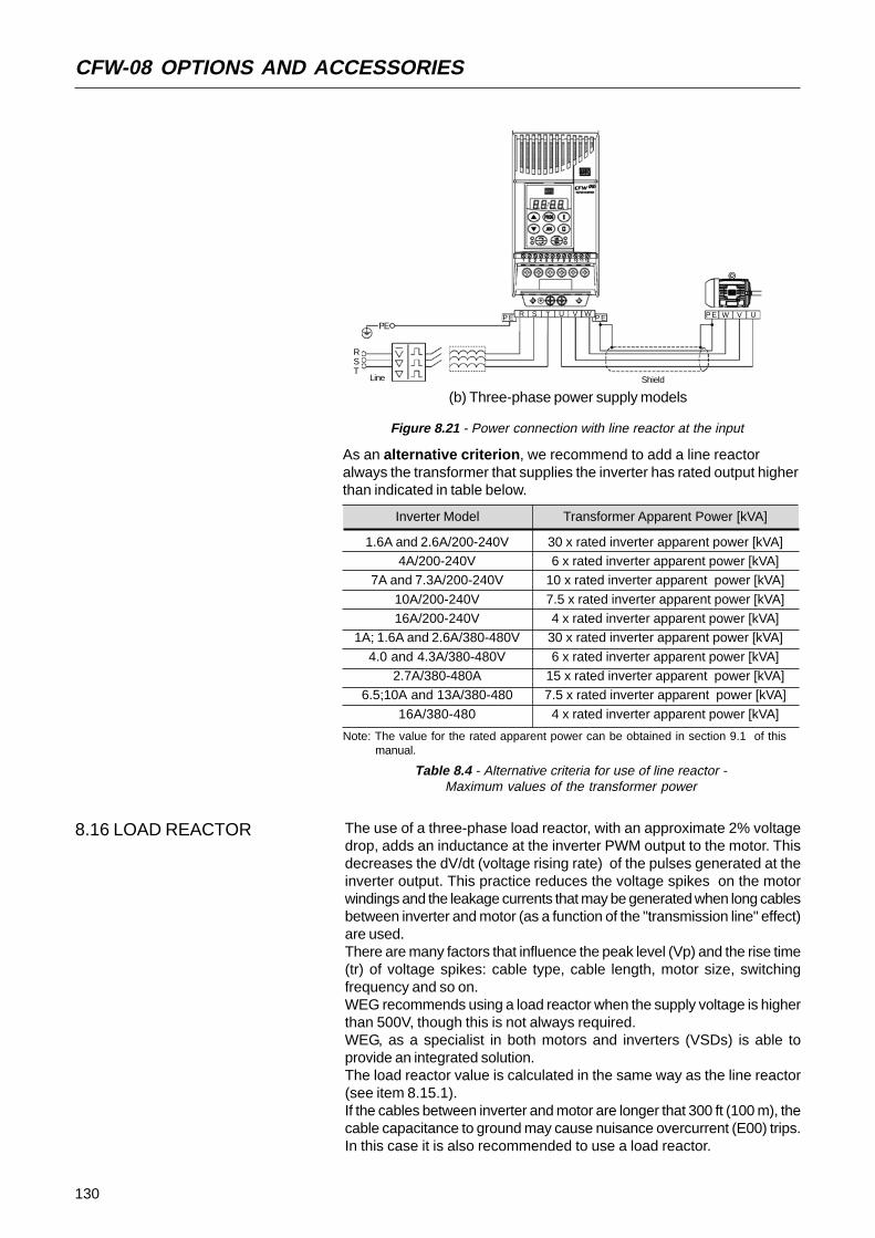
130
CFW-08 OPTIONS AND ACCESSORIES
(b) Three-phase power supply models
Figure 8.21 - Power connection with line reactor at the input
Shield
P E UVW
RST
RP E S T U V W P E
Line
PE
As an alternative criterion, we recommend to add a line reactoralways the transformer that supplies the inverter has rated output higherthan indicated in table below.
Table 8.4 - Alternative criteria for use of line reactor -Maximum values of the transformer power
Transformer Apparent Power [kVA]
1.6A and 2.6A/200-240V4A/200-240V
7A and 7.3A/200-240V
10A/200-240V16A/200-240V
1A; 1.6A and 2.6A/380-480V
4.0 and 4.3A/380-480V2.7A/380-480A
6.5;10A and 13A/380-480
16A/380-480
30 x rated inverter apparent power [kVA]6 x rated inverter apparent power [kVA]
10 x rated inverter apparent power [kVA]
7.5 x rated inverter apparent power [kVA]4 x rated inverter apparent power [kVA]
30 x rated inverter apparent power [kVA]
6 x rated inverter apparent power [kVA]15 x rated inverter apparent power [kVA]7.5 x rated inverter apparent power [kVA]
4 x rated inverter apparent power [kVA]
Inverter Model
Note: The value for the rated apparent power can be obtained in section 9.1 of thismanual.
The use of a three-phase load reactor, with an approximate 2% voltagedrop, adds an inductance at the inverter PWM output to the motor. Thisdecreases the dV/dt (voltage rising rate) of the pulses generated at theinverter output. This practice reduces the voltage spikes on the motorwindings and the leakage currents that may be generated when long cablesbetween inverter and motor (as a function of the "transmission line" effect)are used.There are many factors that influence the peak level (Vp) and the rise time(tr) of voltage spikes: cable type, cable length, motor size, switchingfrequency and so on.WEG recommends using a load reactor when the supply voltage is higherthan 500V, though this is not always required.WEG, as a specialist in both motors and inverters (VSDs) is able toprovide an integrated solution.The load reactor value is calculated in the same way as the line reactor(see item 8.15.1).If the cables between inverter and motor are longer that 300 ft (100 m), thecable capacitance to ground may cause nuisance overcurrent (E00) trips.In this case it is also recommended to use a load reactor.
8.16 LOAD REACTOR

131
CFW-08 OPTIONS AND ACCESSORIES
Figure 8.22 - Load Reactor Connection
8.18 DYNAMIC BRAKING The dynamic braking is used where short deceleration times are requiredor where high inertia is present.For the correct sizing of the braking resistor, application data such as,deceleration time, load inertia, braking duty cycle must be considered.In any case, the rms current capacity and the maximum peak currentmust be considered.The maximum peak current defines the minimum permitted ohmic valuefor the braking resistor. Refer to table 8.4.The DC link voltage level for the actuation of the dynamic braking is asfollows:
Inverter supplied with 200...240V: 375VccInverters supplied with 380...480V: 750Vcc
RST
PE PER S T U V W UVW
8.18.1 Resistor Sizing The braking torque, that can be obtained through the frequency inverter,without using the dynamic braking module, varies from 10 to 35% of therated motor torque. During the deceleration process, the kinetic energy ofthe load is regenerated into the inverter DC link. This energy loads up thecapacitors by increasing the DC link voltage. When this energy is notfully dissipated, it may generate a DC link overvoltage trip (E01) anddisabling the inverter.To obtain higher braking torques, the use of dynamic braking isrecommended where the excess of the regenerated energy is dissipatedin a resistor mounted externally to the inverter. The braking resistor isdefined according to the deceleration time, load inertia and resistive torque.In most cases, a resistor with an ohmic value as indicated on the tablebelow and a power rating of 20% of the driven motor can be used.Use wire type or tape type resistors with suitable insulation to withstandthe instantaneous current peaks.For critical applications with very short braking times, high inertia loads(ex.: centrifuges) or with very short and frequent duty cycles, contactWEG to define the most suitable resistor.
PE
DISCONNECTINGSWITCH
PE
LOADREACTOR
SHIELD

132
CFW-08 OPTIONS AND ACCESSORIES
Inverter Model
1.6A / 200-240V2.6A / 200-240V
4.0A / 200-240V7.0A / 200-240V7.3A / 200-240V
10A / 200-240V16A / 200-240V1.0A / 380-480V
1.6A / 380-480V2.6A / 380-480V2.7A / 380-480V
4.0A / 380-480V4.3A / 380-480V6.5A / 380-480V
10A / 380-480V13A / 380-480V16A / 380-480V
Maximum
Braking Current
10 A
15 A20 A
6 A
6 A8 A
16 A24 A24 A
RMSBraking
Current (*1)
5 A
7 A10 A
3.5 A
3.5 A4 A
10 A14 A14 A
Recommended
Resistor
39 Ω27 Ω22 Ω
127 Ω
127 Ω100 Ω47 Ω33 Ω33 Ω
RecommendedWiring
2.5 mm2 / 14 AWG
2.5 mm2 / 14 AWG4 mm2 / 12 AWG
1.5 mm2 / 16 AWG
1.5 mm2 / 16 AWG2.5 mm2 / 14 AWG4 mm2 / 12 AWG
6 mm2 / 10 AWG6 mm2 / 10 AWG
Pmax
(Maximum
Resistor Power)
3.9 kW
6.1 kW8.8 kW
4.6 kW
4.6 kW6.4 kW
12 kW19 kW19 kW
Prated
(Rated
Resistor Power)
0.98 kW
1.3 kW2.2 kW
1.6 kW
1.6 kW1.6 kW
4.7 kW6.5 kW6.5 kW
Braking not available
Braking not available
Braking not available
Table 8.5 - Recommended Braking Resistors
(*1) The rms braking current can be determined by:
Irms
= Imax
. tbr[min]
5
where tbr corresponds to the sum of the braking times during the mostsevere 5 minute cycle.
8.18.2 Installation Connect the braking resistor between the +UD and BR power terminals(refer to section 3.2.2).Make this connection with a twisted pair. Run this cable separatelyfrom any signal or control wire. Size the cable cross section accordingto the application, by considering the maximum and the rms current.If the braking resistor is installed inside the inverter panel, considerthe heat dissipated by the resistor when defining the panel ventilation.
DANGER!The internal inverter braking circuit and the braking resistor can be damagedwhen not correctly sized or when the line voltage exceeds the maximumallowed valueIn this case, the only guaranteed method to avoid burning the brakingresistor and eliminate risk of fire is the installation of a thermal overloadrelay in series connected with the resistor and/or the installation of athermostat on the resistor body, wiring it in such a way that it disconnectsthe inverter power supply in case of overheating, as shown in figure 8.22below:

133
CFW-08 OPTIONS AND ACCESSORIES
Figure 8.23 - Braking resistor connection(only for models 7.3-10-16A/200-240V e 2.7-4.3-6.5-10-13-16/380-480V)
8.19 SERIALCOMMUNICATION
MOTORPOWERSUPPLY
CONTACTOR
CONTROL POWERSUPPLY
OVERLOADRELAY
THERMOSTATBRAKING
RESISTOR
U
V
W
R
S
T
BR +UD
Master PC, PLC, etc.
Slave 1(Inverter)
Slave 2(Inverter)
Slave n(Inverter)
n ≤ 30 for WEG Protocoln ≤ 247 for Modbus-RTU
8.19.1 Introduction The basic objective of the serial communication is the physical connectionof the inverters in an equipment network configured as follows:
The inverters have a control software for data transmission/reception throughserial interface, thus facilitating the reception of data that have been sentby the master and the transmission of the data requested by the master.
This software supports WEG protocol and nine different Modbus-RTUmodes, that can be selected via parameter P312. The subjects broachedin this Section refers to WEG protocol. For more details about the Modbus-RTU, see item 8.19.
The transfer rate is 9600 bits/s, following an exchange protocol of question/answer typeby using ASCII characters.The master is able to realize the following operations related to eachinverter:
134
CFW-08 OPTIONS AND ACCESSORIES
- IDENTIFICATIONnetwork address;inverter;software version.
- CONTROLgeneral enabling/disabling;enabling/disabling by ramp;direction of rotation;frequency/speed reference;local/remote;JOG;error and fault RESET.
- STATUS RECOGNITIONready;Sub;run;local/remote;error;JOG;direction of rotation.
- PARAMETER READING
- CHANGE OF PARAMETERS
Typical examples of network use:PC (master) for the parametrization of one or several inverters at thesame time;SDCD monitoring inverter variables;PLC controlling the operation of one or more inverters in a industrialprocess.
8.19.2 Interfaces Description The physical connection between the inverters and the master is performedaccording to one of the standards below:a. RS-232 (point-to-point up to 10m);b. RS-485 (multipoint, galavanic isolation, up to 1000m);
8.19.2.1 RS-485 This interface permits the linkage of up to 30 inverters to a master (PC,PLC, etc.), attributing and setting for each inverter an address (1 to 30). Inaddition to these 30 addresses, there are two addresses to perform specialtasks:
Address 0: any inverter in the network is inquired, independently of itsaddress. Only one inverter can be connected to the network (point-to-point) in order to prevent short-circuits in the line interface.

135
CFW-08 OPTIONS AND ACCESSORIES
ADDRESS(P308)
0123456789
10111213141516171819202122232425262728293031
ASCIICHAR DEC HEX
@ 64 40A 65 41B 66 42C 67 43D 68 44E 69 45F 70 46G 71 47H 72 48I 73 49J 74 4AK 75 4BL 76 4CM 77 4DN 78 4EO 79 4FP 80 50Q 81 51R 82 52S 83 53T 84 54U 85 55V 86 56W 87 54X 88 58Y 89 59Z 90 5A] 91 5B\ 92 5C[ 93 5D^ 94 5E_ 95 5F
Address 31: a control can be transmitted to all inverters in the networksimultaneously, without acceptance recognition.List of addresses and corresponding ASCII characters.
ASCIICODE DEC HEX
0 48 301 49 312 50 323 51 334 52 345 53 356 54 367 55 378 56 389 57 39= 61 3D
STX 02 02ETX 03 03EOT 04 04ENQ 05 05ACK 06 06NAK 21 15
Other ASCII characters used by the protocol
The connection between the network participants is performed through apair of wires. The signal levels are according to the EIA RS-485 STANDARDwith differential receivers and transmitters. You must use the serialcommunication module KCS-CFW-08 (refer to section 8.9) connected tothe external module MIW-02 (refer to section 8.13 and/or to MIW-02 UserManual Cod. 0899.4435).When the master is fitted only with a RS-232 serial interface, you mustapply a level conversion module from RS-232 to RS-485.
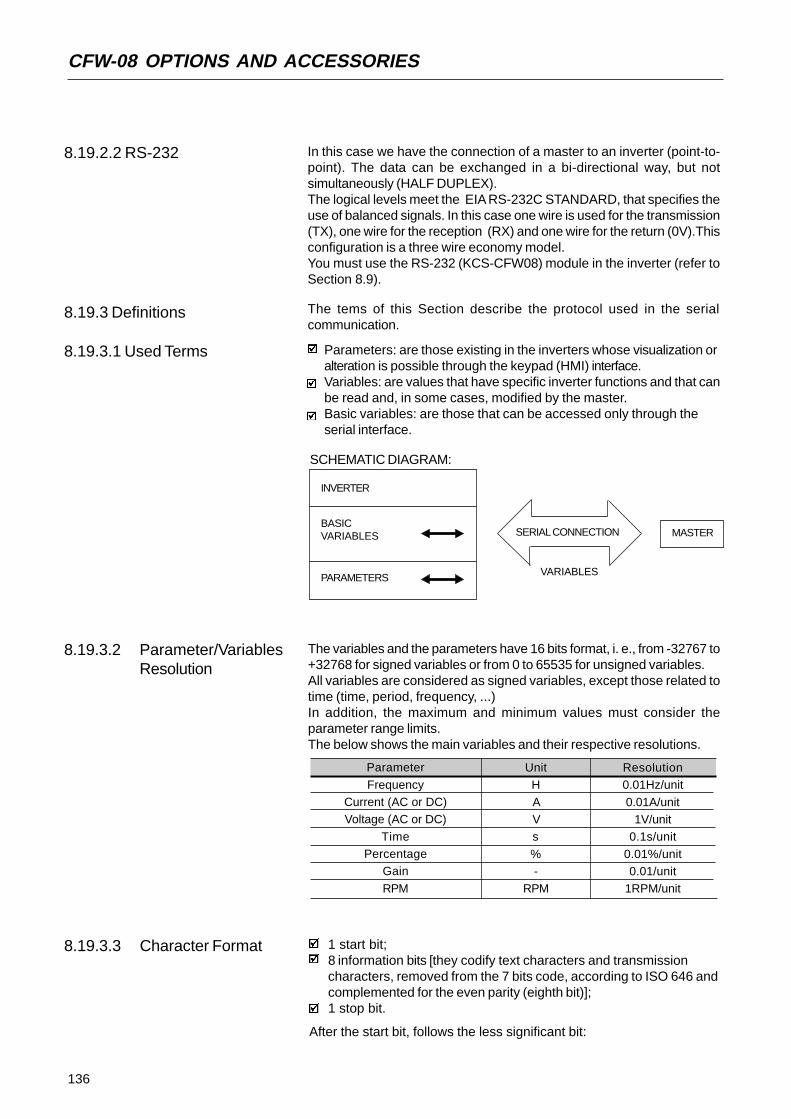
136
CFW-08 OPTIONS AND ACCESSORIES
In this case we have the connection of a master to an inverter (point-to-point). The data can be exchanged in a bi-directional way, but notsimultaneously (HALF DUPLEX).The logical levels meet the EIA RS-232C STANDARD, that specifies theuse of balanced signals. In this case one wire is used for the transmission(TX), one wire for the reception (RX) and one wire for the return (0V).Thisconfiguration is a three wire economy model.You must use the RS-232 (KCS-CFW08) module in the inverter (refer toSection 8.9).
8.19.2.2 RS-232
8.19.3 Definitions The tems of this Section describe the protocol used in the serialcommunication.
8.19.3.1 Used Terms Parameters: are those existing in the inverters whose visualization oralteration is possible through the keypad (HMI) interface.Variables: are values that have specific inverter functions and that canbe read and, in some cases, modified by the master.Basic variables: are those that can be accessed only through theserial interface.
SCHEMATIC DIAGRAM:
INVERTER
BASICVARIABLES
PARAMETERS
MASTERSERIAL CONNECTION
VARIABLES
8.19.3.2 Parameter/VariablesResolution
1 start bit;8 information bits [they codify text characters and transmissioncharacters, removed from the 7 bits code, according to ISO 646 andcomplemented for the even parity (eighth bit)];1 stop bit.
After the start bit, follows the less significant bit:
8.19.3.3 Character Format
UnitH
AVs
%-
RPM
Resolution0.01Hz/unit
0.01A/unit1V/unit
0.1s/unit
0.01%/unit0.01/unit
1RPM/unit
Parameter
FrequencyCurrent (AC or DC)Voltage (AC or DC)
TimePercentage
Gain
RPM
The variables and the parameters have 16 bits format, i. e., from -32767 to+32768 for signed variables or from 0 to 65535 for unsigned variables.All variables are considered as signed variables, except those related totime (time, period, frequency, ...)In addition, the maximum and minimum values must consider theparameter range limits.The below shows the main variables and their respective resolutions.

137
CFW-08 OPTIONS AND ACCESSORIES
READING MESSAGE: for inquiring of the inverter variable content;
WRITING MESSAGE: to change the inveter variable content or tosend comands to the inverters.
NOTE:No transmission between two inverters is possible.The master has the bus access control.
8.19.3.4.1 Reading Message This message allows the master receive from the inverter the content thatcorresponding to the inquiry code. In the answer message, the invertertransmits the data requested by the master and it finishes thetransmission with EOT.
2) Inverter:
ADDR STX = ETX BCC
CODE VAL
TEXT
EOT ADDR ENQ
CODE
Format of the reading message:
EOT: control character of End Of Transmission;ADR: inverter address (ASCII@, A, B, C, ...) (ADdRess);CODE: address of the 5-digit variable coded in ASCII;ENQ: control character ENQuiry (enquiry);
Format of the inverter answer message:
ADR: 1 character - inverter address;STX: control character - Start of TeXt;TEXT: consists in:
CODE: address of the variable;“ = “: separation character;VAL: 4 digits value HEXADECIMAL;
3) Master:
EOT
1) Master:
START B1 B2 B3 B4 B5 B6 B7 B8 STOP
Startbit
Stopbit
8 bits of information
8.19.3.4 Protocol The transmission protocol meets the Standard ISO 1745 for thetransmission in code.Only text character sequences without headers are used. The error/fault monitoring is made through transmission related to the parity of theindividual 7 bit characters, according to ISO 646. The parity monitoringis made according to DIN 66219 (even parity). The master uses twotypes of messages:
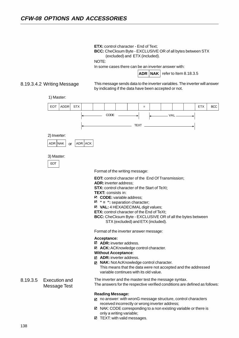
138
CFW-08 OPTIONS AND ACCESSORIES
This message sends data to the inverter variables. The inverter will answerby indicating if the data have been accepted or not.
8.19.3.4.2 Writing Message
Format of the writing message:
EOT: control character of the End Of Transmission;ADR: inverter address;STX: control character of the Start of TeXt;TEXT: consists in:
CODE: variable address;“ = “: separation character;VAL: 4 HEXADECIMAL digit values;
ETX: control character of the End of TeXt;BCC: CheCksum Byte - EXCLUSIVE OR of all the bytes between
STX (excluded) and ETX (included).
Format of the inverter answer message:
Acceptance:ADR: inverter address.ACK: ACKnowledge control character.
Without Acceptance:ADR: inverter address.NAK: Not AcKnowledge control character.This means that the data were not accepted and the addressedvariable continues with its old value.
The inverter and the master test the message syntax.The answers for the respective verified conditions are defined as follows:
Reading Message:no answer: with wronG message structure, control charactersreceived incorrectly or wrong inverter address;NAK: CODE corresponding to a non existing variable or there isonly a writing variable;TEXT: with valid messages.
8.19.3.5 Execution andMessage Test
ADR NAK refer to Item 8.18.3.5
ETX: control character - End of Text;BCC: CheCksum Byte - EXCLUSIVE OR of all bytes between STX
(excluded) and ETX (included).NOTE:In some cases there can be an inverter answer with:
1) Master:
EOT ADDR STX = ETX BCC
CODE VAL
TEXT
2) Inverter:
ADR NAK ADR ACKor
3) Master:
EOT

139
CFW-08 OPTIONS AND ACCESSORIES
The messages are processed in the inverter in determined intervals.Therefore, a pause larger than the sum of the times T
proc + T
di + T
txi
should be ensured between two messages addressed to the same inver-ter (refer to section 8.18.6.).
8.19.3.6 MessageSequence
8.19.3.7 Variable Code The field designated with CODE determines the parameter address andthe basic variables formed by 5 digits (ASCII characters) as follows:
8.19.4 Message Examples Change of the minimum frequency (P133) to 6.00Hz in the inverter 7.
1) Master:
Fmin Fmin=258H=600=6.00/0.01
addr. 7
2) Inverter:
G ACK
Writing Message:no answer: with wrong message structure, control charactersreceived incorrectly or wrong inverter address;NAK: CODE corresponding to a non existing variable, wrong BCC(checksum byte), only reading variable, VAL out of the allowedrange for the respective variable, operation parameter out of the alterationmode;ACK: with valid message;
The master should maintain, between two variable transmissions to thesame inverter, a waiting time that is compatible with the used inverter.
CODE X X X X X
Number of the basic variable or parameter
Equipment number:"7" = CFW08"9" = any inverter
Specifier:0 = basic variables1 = P000 to P0992 = P100 to P1993 = P200 to P2994 = P300 to P3995 = P400 to P4996 = P500 to P5997 = P600 to P699
Equal to zero (0)
EOT G STX 0 2 7 3 3 = 0H 2H 5H 8H ETX BCC
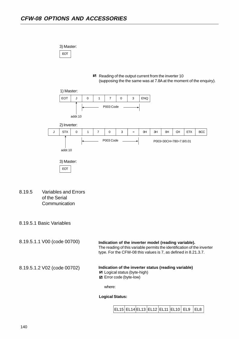
140
CFW-08 OPTIONS AND ACCESSORIES
3) Master:
EOT
Reading of the output current from the inverter 10(supposing the the same was at 7.8A at the moment of the enquiry).
1) Master:
EOT J 0 1 7 0 3 ENQ
P003 Code
addr.10
2) Inverter:
P003 Code P003=30CH=780=7.8/0.01
addr.10
3) Master:
EOT
8.19.5 Variables and Errorsof the SerialCommunication
8.19.5.1 Basic Variables
8.19.5.1.1 V00 (code 00700) Indication of the inverter model (reading variable).The reading of this variable permits the identification of the invertertype. For the CFW-08 this values is 7, as defined in 8.21.3.7.
8.19.5.1.2 V02 (code 00702) Indication of the inverter status (reading variable)Logical status (byte-high)Error code (byte-low)
where:
Logical Status:
EL15 EL14 EL13 EL12 EL11 EL10 EL9 EL8
J STX 0 1 7 0 3 = 0H 3H 0H CH ETX BCC
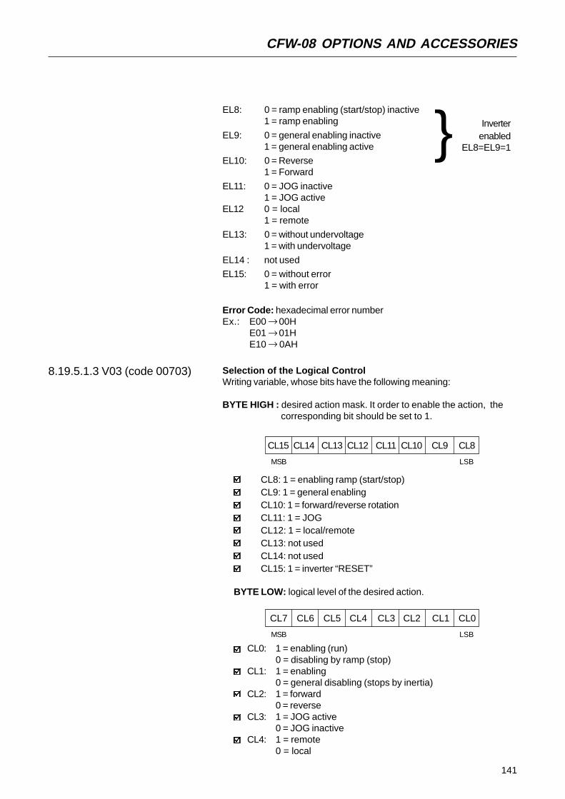
141
CFW-08 OPTIONS AND ACCESSORIES
EL8: 0 = ramp enabling (start/stop) inactive1 = ramp enabling
EL9: 0 = general enabling inactive1 = general enabling active
EL10: 0 = Reverse1 = Forward
EL11: 0 = JOG inactive1 = JOG active
EL12 0 = local1 = remote
EL13: 0 = without undervoltage1 = with undervoltage
EL14 : not used
EL15: 0 = without error1 = with error
Inverterenabled
EL8=EL9=1
8.19.5.1.3 V03 (code 00703)
Error Code: hexadecimal error numberEx.: E00 00H
E01 01HE10 0AH
→→→
Selection of the Logical ControlWriting variable, whose bits have the following meaning:
BYTE HIGH : desired action mask. It order to enable the action, the corresponding bit should be set to 1.
BYTE LOW: logical level of the desired action.
CL8: 1 = enabling ramp (start/stop)CL9: 1 = general enablingCL10: 1 = forward/reverse rotationCL11: 1 = JOGCL12: 1 = local/remoteCL13: not usedCL14: not usedCL15: 1 = inverter “RESET”
CL15 CL14 CL13 CL12 CL11 CL10 CL9 CL8
MSB LSB
CL7 CL6 CL5 CL4 CL3 CL2 CL1 CL0
MSB LSB
CL0: 1 = enabling (run)0 = disabling by ramp (stop)
CL1: 1 = enabling0 = general disabling (stops by inertia)
CL2: 1 = forward0 = reverse
CL3: 1 = JOG active0 = JOG inactive
CL4: 1 = remote0 = local

142
CFW-08 OPTIONS AND ACCESSORIES
CL5: not usedCL6: not usedCL7: the transition in this bit from 0 to 1 causes the inverter “RESET”
when any error condition is present.
Note:Disabling via DIx has priority over this disabling.To disable the inverter via serial interface, set CL0=CL1=CL8=CL9=1,while the external disabling (example, via DI) must be inactive.If CL1=0 and CL9=1, it will occur general disabling.If CL0=0 and CL8=1, the inverter will be disabled via ramp.
8.19.5.1.4 V04 (code 00704) Frequency reference is given by the serial interface (reading/writingvariable). Permite enviar a referência de frequência (em Hz) para o inver-sor, desde que P221=5 para o modo local e P222=5 para o modo remoto.A resolução desta variável é mostrada no item 8.18.3.2.
Inverter enabling (provided P229=2 for LOC or P230=2 for REM)
8.19.5.1.6 Message Examples withBasic Variables
8.19.5.1.5 V05 (code 00705)
CHSL0: 1 - serial local referenceCHSL1: 1 - serial local forward/reverse selectionCHSL2: 1 - serial local On/Off selectionCHSL3: 1 - serial local JOGCHSL4: 1 - serial remote referenceCHSL5: 1 - serial remote forward/reverse selectionCHSL6: 1 - serial remote On/Off selectionCHSL7: 1 - serial remote JOG selectionCHSH0: 1 - serial local/remote selection.
CHSH CHSL CHSL CHSLCHSL CHSL CHSLCHSL CHSL0 7 6 5 4 3 2 1 0
MSB LSB
Changing inverter from forward to reverse (provided P229=2 for LOC or P230=2 for REM) -If P231 = 2
1) Master:
C. L. Code general enabling=1 ramp enabling=1
addr. 7
2) Inverter:
G ACK
3) Master:
EOT
Enabled controls by the serial interface (reading variable)
EOT G STX 0 0 8 0 3 = 0H 3H 0H 3H ETX BCC
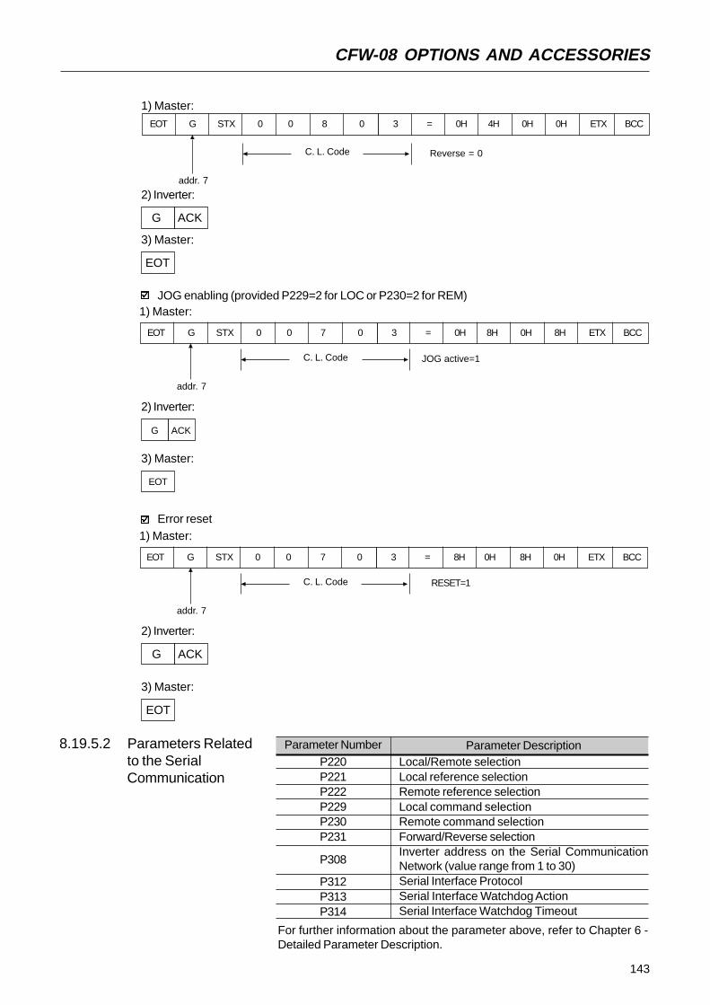
143
CFW-08 OPTIONS AND ACCESSORIES
8.19.5.2 Parameters Relatedto the SerialCommunication
Parameter DescriptionLocal/Remote selectionLocal reference selectionRemote reference selectionLocal command selectionRemote command selectionForward/Reverse selectionInverter address on the Serial CommunicationNetwork (value range from 1 to 30)Serial Interface ProtocolSerial Interface Watchdog ActionSerial Interface Watchdog Timeout
Parameter NumberP220P221P222P229P230P231
P308
P312P313P314
Error reset1) Master:
C. L. Code RESET=1
addr. 7
2) Inverter:
G ACK
3) Master:
EOT
EOT G STX 0 0 7 0 3 = 8H 0H 8H 0H ETX BCC
1) Master:
C. L. Code Reverse = 0
addr. 7
EOT G STX 0 0 8 0 3 = 0H 4H 0H 0H ETX BCC
2) Inverter:
G ACK
3) Master:
EOT
JOG enabling (provided P229=2 for LOC or P230=2 for REM)1) Master:
C. L. Code JOG active=1
addr. 7
2) Inverter:
G ACK
EOT G STX 0 0 7 0 3 = 0H 8H 0H 8H ETX BCC
3) Master:
EOT
For further information about the parameter above, refer to Chapter 6 -Detailed Parameter Description.

144
CFW-08 OPTIONS AND ACCESSORIES
They act as follows:they do not disable the inverter;they do not disable the fault relay;they inform in the word the logical status (V02).
Fault types:E22: longitudinal parity fault (BCC);E24: parametrization fault (when some of the situations occurs asindicated in table 5.1 (incompatibility between parameters) or whenthere is a parameter change attempt that can not be changed withrunning motor).E25: variable or parameter not existing;E26: expected values out of allowed limits;E27: writing attempt in a read only variable or logical command disabled;E29: serial interface watchdog timeout error.
Note:If a parity fault is detected during inverter data reception, the messagewill be ignored. The same happens when syntax errors occur.Ex.:
Code values different from the numbers 0,...,9;Separation character different from “ = “, etc.
8.19.5.3 Errors Related tothe SerialCommunication
8.19.6 Time for Read/Writeof Messages
MASTER Tx: (data)
RSND (request to send)
INVERTER
TxD: (data)
tproctdi ttxi
Times (ms)T
proc
Tdi
Ttxi
reading writing
Typical10215
3

145
CFW-08 OPTIONS AND ACCESSORIES
8.19.7 PhysicalConnectionRS-232 and RS-485
Note:The wiring of the RS-232 must be laid separately from the power cablesand the control wiring in 110/220V.
NOTE!You can not use RS-232 and RS-485 simultaneously.
Figure 8.24 - CFW-08 network connection through RS-485 serial interface
6
5
4
1
2
3
TX
0V
RX
+5V
RTS
0V
Figure 8.25 - Description of the XC8 (RJ-6) connector
NetworkMaster
(PC, PLC)
RS-485
MIW-02 MIW-02 MIW-02
RS-232
RS-485
CFW-08 CFW-08 CFW-08
BCableshielding
RS-232
RS-485
A B
RS-485XC29
A B
RS-485XC29
RS-232
RS-485
Ω
Notes:LINE TERMINATION: connect the termination resistors at the ends ofthe line.
LINE TERMINATION: include line termination (120 ) at the ends, andonly at the line ends.GROUNDING OF THE CABLE SHIELD: connect the shielding to theequipment frame (suitable grounding);RECOMMENDED CABLE: for balanced shielding.Ex.: AFS series, manufacturer KMP.
Figure below shows the pin position of the XC8 connector of the KCS-CFW08-S module.

146
CFW-08 OPTIONS AND ACCESSORIES
Figure 8.26 - Message Structure
Master Query MessageAddress (1 byte)
Function Code (1 byte)
Data (n bytes)CRC (2 bytes)
Address (1 byte)Function Code (1 byte)
Data (n bytes)CRC (2 bytes)
Slave Answer Message
Start B0 B1 B2 B3 B4 B5 B6 B7 Parity or Stop Stop
8.20 MODBUS-RTU
8.20.1 Introduction toModbus-RTU Protocol
Modbus protocol has been already developed 1979 firstly. Currently it is awide diffused open protocol, used by several manufacturers in differentequipment. The Modbus-RTU communication of the do CFW-08 has beendeveloped by considering two documents:
1. MODBUS Protocol Reference Guide Rev. J, MODICON, June 1996.2. MODBUS Application Protocol Specification, MODBUS.ORG,
may 8th 2002.
In these documents are defined the format of the messages used bythese elements that are part of the Modbus network, the services (orfunctions) that can be made available via network, and also how theseelements exchange the data on the network.
8.20.1.1 TransmissionModes
In the RTU mode each transmitted word has 1 start bit, eight data bits, 1parity bit (optional) and 1 stop bit (2 stop bits, if parity bit is not used).Thus the bit sequence for the transmission is as follows:
8.20.1.2 Message Structure In RTU ModeThe Modbus RTU network operates in Master-Slave systemand it can consist of up to 247 slaves but only one Master. The masteralways initiates the communication with a question to a slave and theslave answers the question. Both messages (question and answer) havethe same structure: Address, Function Code, and CRC. Depending onwhat is being requested, only the data field has variable length.
Two transmission modes are defined in the protocol definition: ASCII andRTU. The transmission modes define the form how the message bytesare transmitted. It is not permitted to use the two transmission modes onthe same network.In the RTU mode each transmitted word has one start bit, eight data bits,1 parity bit (optional) and 1 stop bit (2 stop bits, if no parity bit is used).Thus the bit sequence for the transmission of 1 byte is as follows:

147
CFW-08 OPTIONS AND ACCESSORIES
8.20.1.2.1 Address The master initiates the communication by sending one byte with theaddress of the slave to which the message is addressed. The slave withthe right slave address initiates the message with its own address. Themaster can also send a message destined to address 0 (zero), whichmeans that the message is destined to all network slaves (broadcast). Inthis case no slave will answer to the master.
8.20.1.2.2 Function Code This field contains an only byte, where the master specifies the type ofservice or the function requested to the slave (read, write, etc.). Accordingto the protocol, each function is used to access a specific data type. Inthe CFW-08 all data are available as holding type registers (referencedfrom the address 40000 or’ 4x’). Besides these registers, the inverterstatus (enabled/disabled, with error/no error and the command for theinverter (run/stop, run CW/CCW, etc.) can be also accessed through thecoils read/write functions or the internal bits (referenced from the address00000 or ‘0x’ on).
8.20.1.2.3 Data Field This field has variable length. The format and the content of this fielddepend on the used function and transmitted values. This field and therespective functions are described in item 8.20.3.
8.20.1.2.4 CRCThe last part of the message is the field for checking the transmissionerrors. The used method is the CRC-16 (Cycling Redundancy Check).This field is formed by two bytes, where the least significant byte (CRC-)is transmitted first and only then the most significant byte is transmitted(CRC+).CRC calculation is started by loading a 16-bit variable (mentioned fromnow on as CRC variable) with FFFFh value. Then following steps areexecuted with the following routine:
1. The first message byte (only the data bits - the start bit, parity bit andstop bit are not used) is submitted to the XOR logic (OR exclusive)with the 8 least significant bits of the CRC variable, returning the resultto the CRC variable,
2. Then the CRC variable is displaced one position to the right, in thedirection of the least significant bit and the position of the mostsignificant bit is filled out with zero 0 (zero).
3. After this displacement, the flag bit (bit that has been displaced outthe CRC variable) is analyzed, by considering the following:
If the bit value is 0 (zero), no change is made.If the bit value is 1, the CRC variable content is submitted to XORlogic with a constant A001h value and the value is returned to theCRC variable.
4. Repeat steps 2 and 3 until the eight displacements have been realized.5. Repeat the steps 1 to 4, by using the next byte message until the
whole message have been processed. The end content of the CRCvariable is the value of the CRC field that is transmitted at the end ofthe message. The least significant part is transmitted first (CRC), onlythen the most significant part (CRC+) is transmitted.

148
CFW-08 OPTIONS AND ACCESSORIES
8.20.1.2.5 Times betweenMessages
In the RTU mode there is no specific character that indicates the beginningor the end of a message. Thus the only indication for the beginning or theend of a new message is the data transmission absence in the networkby 3.5 times the time required for transmission of one data word (11 bits).Thus if a message is initiated after elapsing of the minimum time requiredwithout transmission, the network elements assume that the receivedcharacter represents the beginning of a new message. In similar mode,after this time has elapsed, the network elements will assume that themessage has been ended.
If during the transmission of a message, the time between the bytes islonger than this minimum required time, the message will be consideredinvalid, since the inverter will discard the already received bytes and willmount a new message with the bytes that are being transmitted.The table below shows the time for three different communication rates.
8.20.2 Operation of theCFW-08 in theModbus-RTUNetwork
The CFW-08 frequency inverters operate as slaves of the Modbus-RTUnetwork. The communication initiates with the master of the Modbus-RTUnetwork requesting a service for a network address. When the inverter isconfigured to the corresponding address, it processes the question andanswers to the master as requested.
8.20.2.1 Interface Description The CFW-08 frequency inverters use a serial interface for thecommunication with the Modbus-RTU network. There are two ways toperform the connection between the network master and the CFW-08:
Figure 8.25 - Times required during the communication of a message
T11 bits
= Time to transmit one word of the message.T
entre bytes= Time between bytes (can not be longer than T
3,5x).
T3,5x
= Minimum interval to indicate the begin and the end of themessage (3,5 x T
11bits).
Signal
Time T11 bits
T3,5 x Tbetween bytesT3,5 x
Message
Comunicação T11 bits T3,5x
9600 kbits/sec 1,146 ms 4,010 ms
19200 kbits/sec 573 µs 2,005 ms38400 kbits/sec 285 µs 1,003 ms

149
CFW-08 OPTIONS AND ACCESSORIES
8.20.2.1.1 RS-232 The interface is used for the point-to-point connection (between a singleslave and the master).Max. distance: 10 meters.Signal levels according to EIA STANDARD RS-232C.Three wires: transmission (TX), reception (RX) and return (0V).The RS-232 module (KCS-CFW08) must be used (see item 8.9).
8.20.2.1.2 RS-485 This interface is used for multipoint connection (several slaves and themaster).Max. distance: 1000 meters (use of shielded cables).Signal levels according to EIA STANDARD RS-485.The RS-232 module (KCS-CFW08) must be used (see item 8.9),connected to the external module MIW-02, to convert from RS-232 toRS-485 (see item 8.14).
Note: for connection, see 8.19.7
8.20.2.2 InverterConfiguration in theModbus-RTUNetwork
To ensure a correct communication in the network, you must configurethe inverter address in the network as well as the transfer rate and theexisting parity type, besides the correct physical connection.
8.20.2.2.1 Inverter Address inthe Network
The inverter address is defined through the parameter P308.If the serial communication type (P312) has been configured to Modbus-RTU, you may select the addresses from 1 to 247.Each slave shall have a different address.The master does not have address.The slave address must be known, even when connection is madepoint-to-point.
8.20.2.2.2 Transmission Rateand Parity
Both configurations are defined by parameter P312.Baud rates: 9600, 19200 or 38400 kbits/sec.Parity: None, odd parity, even parity.All slaves and even the network master must use the same baud rateand parity.
8.20.2.3 Access to theInverter Data
All parameters and available basic variables for the CFW-08 can beaccessed through the network:
Parameters: are those set in the inverter and that can be displayedand changed through the HMI (Human-Machine Interface) (see item 1- Parameters).Basic Variables: are the internal inverter variables that can be accessedonly through serial interface. For instance, trough these basic variablesyou can change the speed reference, read the inverter status, enableor disable the inverter, etc. (see item 8.19.5.1 - Basic Variables).Register: nomenclature used to represent both parameters and basicvariables during data transfer.Internal Bits: bits that are accessed only through the serial interfaceand that are used for inverter status controlling and monitoring.
Item 8.19.3.2 defines the resolution of the parameters and variablestransmitted via serial interface.

150
CFW-08 OPTIONS AND ACCESSORIES
8.20.2.3.1 Available Functionsand ResponseTimes
In the Modbus RTU protocol specification is defined the functions used foraccessing different types of registers described in the specification. In theCFW-08 both parameters and basic variables are defined as being holdingtype registers (referenced as 4x). In addition to these registers, it is alsopossible to access the internal controlling and monitoring bits directly(referenced as 0x).Following services (or functions) are available in the CFW-08 frequencyinverter for accessing these registers:
Read CoilsDescription: reading of internal register blocks or coils.Function code: 01.Broadcast: not supportedResponse time: 10 to 20 ms.
Read Holding RegistersDescription: reading of register blocks of holding type.Function code: 03.Broadcast: not supportedResponse time: 10 to 20 ms.
Write Single CoilDescription: writing in a single internal bit or coil.Function code: 05.Broadcast: supported.Response time: 10 to 20 ms.
Write Single RegisterDescription: writing in a single register of holding type.Function code: 06.Broadcast: supportedResponse time: 10 to 50 ms.
Write Multiple CoilsDescription: writing in internal bit blocks or coils.Function code: 15.Broadcast: supportedResponse time: 10 to 20 ms.
Write Multiple RegistersDescription: writing in register blocks of holding type.Function code: 16.Broadcast: supportedResponse time: 10 to 50 ms for each written register.
Read Device IdentificationDescription: Identification of the inverter model.Function code: 43.Broadcast: not supported.Response time: 10 to 20 ms.
Note: The Modbus RTU network slaves are addressed from 1 to 247.Master uses address 0 to send messages that are common to all slaves(broadcast)
8.20.2.3.2 Data Addressingand Offset
The CFW-08 data addressing is realized with an offset equal to zero thatmeans that the address number is equal to the register number. Theparameters are available from address 0 (zero) on, whilst the basicvariables are available from address 5000 on. In same way, the status bitsare made available from address 0 (zero) on and the control bits are madeavailable from address 100 on.Table below shows the addressing of bits, parameters and basic variables:

151
CFW-08 OPTIONS AND ACCESSORIES
... ... ...
... ... ...
... ... ...
Basic Variables Modbus Address
Decimal Hexadecimal
V00 5000 1388hV01 5001 1389h
V05 5005 138Dh
Number of theBasic Variable
Note: All registers (parameters and basic variables) are considered asholding type registers, referenced from 40000 or 4x, whilst the bits arereferenced from 0000 or 0x.The status bits have the same functions of the bits 8 to 15 of the logicstatus (basic variable 2). These bits are available only for read, thus anyattempt to write command returns error status to the master.
Parameters
Parameter Number Endereço Modbus
Decimal HexadecimalP000 0 0000h
P001 1 0001h
P100 100 0064h
... ... ...
Status Bits Modbus Address
Decimal Hexadecimal
Bit 0 00 00hBit 1 01 01h
Bit 7 07 07h
Bit Number
... ... ...Commands Bits
Modbus Address Decimal Hexadecimal
Bit 100 100 64hBit 101 101 65h
Bit 107 107 6Bh
Bit Number
Bit Number
Bit 0
Bit 1
Bit 2
Status Bits
Function0 = Ramp enabling inactive1 = Ramp enabling active
0 = General enabling inactive1 = General enabling active0 = Counter-clockwise direction of rotation
1 = Clockwise direction of rotation

152
CFW-08 OPTIONS AND ACCESSORIES
Bit Number
Bit 3
Bit 4
Bit 5
Bit 6
Bit 7
Status Bits
Function
0 = JOG inactive1 = JOG active0 = Local Mode
1 = Remote Mode0 = No undervoltage1 = With undervoltage
Not used0 = No fault1 = With fault
The command bits are available to read and write and they have the samefunction of the logic command bits 0 to 7 (basic variable 3), however norequiring the use of the mask. The basic variable 3 write influences thestatus of these bits.
Bit Number
Bit 100
Bit 101
Bit 102
Bit 103
Bit 104
Bit 105
Bit 106
Bit 107
Command Bits
Function
0 = Ramp disable (stops)1 = Ramp enable (runs)0 = General disable
1 = General enable.0 = Counter-clockwise direction of rotation1 = Clockwise direction of rotation
0 = JOG disable1 = JOG enable0 = Goes to local mode
1 = Goes to remote modeNot usedNot used
0 = It does not reset inverter1 = It resets inverter
8.20.3 Detailed FunctionDescription
This section describes in details the functions that are available in theCFW-08 for the Modbus RTU communication. Please note the followingduring the message preparation:
Values are always transmitted as hexadecimal values. The address of one data, the data number and the value of the registersare always represented through 16 bits. Thus these fields aretransmitted by using two bytes (high and low). To access the bits, andthe form to represent one bit depend on the used function.The messages, both for enquiry and response, cannot be longer than128 bytes.The resolution of each parameter or basic variable is as described initem 8.19.3.2.

153
CFW-08 OPTIONS AND ACCESSORIES
8.20.3.1 Function 01 -Read Coils
It reads the content of an internal group of bits that must compulsorily ina numerical sequence. This function has the following structure for theread and response messages (the values are always hexadecimal, andeach filed represents one byte):
Query (Master)Slave address
Function
Initial bit address (byte high)Initial bit address (byte low)Number of bits (byte high)
Number of bits (byte low)CRC-CRC+
Response (Slave)
Slave addressFunction
Byte Count Field (number of data bytes)
Byte 1Byte 2Byte 3
etc...CRC-CRC+
Each response bit is placed at a position of the data bytes sent by theslave. The first byte, from the bits 0 to 7, receives the first 8 bits from theinitial address indicated by the master. The other bytes (if the number ofthe read bits is higher than 8) remain in the same sequence. If the numberof the read bits is not a multiple of 8, the remaining bits of the last byteshould be filled out with 0 (zero).
Example: reading of the status bits for general enable (bit 1) anddirection of rotation (bit 2) of then CFW-08 at the address 1:
Query (Master)Field Value
Slave address 01h
Function 01hInitial bit address (byte high) 00hInitial bit address (byte low) 01h
Number of bits (byte high) 00hNumber of bits (byte low) 02h
CRC- ECh
CRC+ 0Bh
Response (Slave)Field Value
Slave address 01h
Function 01hByte Count 01h
Status of the bits 1 and 2 02h
CRC- D0hCRC+ 49h
8.20.3.2 Function 03 - ReadHolding Register
It reads the content of a group of registers that must be compulsorily in anumerical sequence. This function has following structure for the readand response messages (the values are always hexadecimal values, andeach field represents one byte):
As the number of read bits in the example is smaller than 8, the slaverequired only 1 byte for the response. The value of the byte was 02h,That as binary value will have the form 0000 0010. As the number of readbits is equal to 2, only the two less significant bits, that have the value 0= general disable and 1 = direction of rotation are of interest, are of interest.The other bits, as they did not be requested, are filled out with 0 (zero).
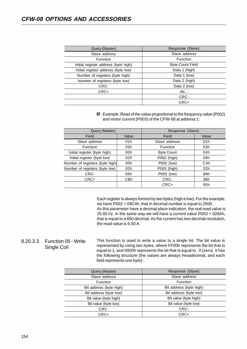
154
CFW-08 OPTIONS AND ACCESSORIES
8.20.3.3 Function 05 - WriteSingle Coil
This function is used to write a value to a single bit. The bit value isrepresented by using two bytes, where FF00h represents the bit that isequal to 1, and 0000h represents the bit that is equal to 0 (zero). It hasthe following structure (the values are always hexadecimal, and eachfield represents one byte):
Example: Read of the value proportional to the frequency value (P002)and motor current (P003) of the CFW-08 at address 1:
Query (Master)Slave address
Function
Initial register address (byte high)Initial register address (byte low)Number of registers (byte high)
Number of registers (byte low)CRC-CRC+
Response (Slave)
Slave addressFunction
Byte Count Field
Data 1 (high)Data 1 (low)Data 2 (high)
Data 2 (low)etc...CRC-
CRC+
Query (Master)Field Value
Slave address 01hFunction 03h
Initial register (byte high) 00h
Initial register (byte low) 02hNumber of registers (byte high) 00hNumber of registers (byte low) 02h
CRC- 65h
CRC+ CBh
Response (Slave)Field Value
Slave address 01hFunction 03h
Byte Count 04h
P002 (high) 09hP002 (low) C4hP003 (high) 02hP003 (low) 8Ah
CRC- 38hCRC+ 95h
Each register is always formed by two bytes (high e low). For the example,we have P002 = 09C4h, that in decimal number is equal to 2500.As this parameter have a decimal place indication, the real read value is25.00 hz. In the same way we will have a current value P003 = 028Ah,that is equal to a 650 decimal. As the current has two decimal resolution,the read value is 6.50 A.
Query (Master)Slave address
Function
Bit address (byte high)Bit address (byte low)Bit value (byte high)
Bit value (byte low)CRC-CRC+
Response (Slave)Slave address
Function
Bit address (byte high)Bit address (byte low)Bit value (byte high)
Bit value (byte low)CRC-CRC+

155
CFW-08 OPTIONS AND ACCESSORIES
8.20.3.5 Function 15 - WriteMultiple Coils
This function allows writing values for a bit group that must be in numericalsequence. This function can be also used to write a single bit (the valuesare always hexadecimal, and each field represents one byte).
Example: to drive a ramp enable command (bit 100 = 1) of a CFW-08at the address 1:
Query (Master)Field Value
Slave address 01h
Function 05hBit number (high) 00hBit number (low) 64h
Bit value (high) FFhBit value (low) 00h
CRC- CDh
CRC+ E5h
Response (Slave)Field Value
Slave address 01h
Function 05hBit number (high) 00hBit number (low) 64h
Bit value (high) FFhBit value (low) 00h
CRC- CDh
CRC+ E5h
8.20.3.4 Function 06 - WriteSingle Register
This function is used to write a value to a single register. This function hasfollowing structure (values are always hexadecimal values, and each fieldrepresents one byte):
For this function, the slave response is an identical copy of the query sentby the master.
Query (Master)Slave address
FunctionRegister address (byte high)Register address (byte low)
Value for the register (byte high)Value for the register (byte low)
CRC-
CRC+
Response (Slave)Slave address
FunctionRegister address (byte high)Register address (byte low)
Value for the register (byte high)
Value for the register (byte low)CRC-CRC+
Example: write of the speed reference (basic variable 4) equal to 30.00 hz ofa CFW-08 at address 1.
Query (Master)
Field ValueSlave address 01h
Function 06h
Register (high) 13hRegister (low) 8ChValue (high) 0Bh
Value (low) B8hCRC- 4BhCRC+ E7h
Response (Slave)
Field ValueSlave address 01h
Function 06h
Register (high) 13hRegister (low) 8ChValue (high) 0Bh
Value (low) B8hCRC- 4BhCRC+ E7h
For this function, the slave response will be again a copy identical to therequest made by the master. As already informed above, the basic variablesare addressed from 5000, thus the basic variable 4 will be addressed at5004 (138Ch). The value for this variable is 30.00 hz, that is representedby 3000 (0BB8h).

156
CFW-08 OPTIONS AND ACCESSORIES
Query (Master)Slave address
Function
Initial bit address (byte high)Initial bit address (byte low)Number of bits (byte high)
Number of bits (byte low)Byte Count Field (number of data bytes)
Byte 1
Byte 2Byte 3etc...
CRC-CRC+
Response (Slave)
Slave addressFunction
Initial bit address (byte high)
Initial bit address (byte low)Number of bits (byte high)Number of bits (byte low)
CRC-CRC+
The value of each bit that is being sent is placed at a position of the databytes sent by the master. The first byte, in the bits 0 to 7, receives the 8first bits by starting from the initial address indicated by the master. Theother bytes (if the number of inscribed bits is higher than 8) remain insequence. If the number of inscribed bits is not a multiple of 8, the remainingbits of the last byte should be filled in with 0 (zero).
Example: command writing for general enabling (bit 100 = 1), generalenabling (bit 101 = 1) and CWW-direction of rotation (bit 102 = 0), fora CFW-08 at address 1:
Query (Master)Field Value
Slave address 01hFunction 0Fh
Initial bit (byte high) 00h
Initial bit (byte low) 64hNumber of bits (byte high) 00hNumber of bits (byte low) 03h
Byte Count 01hBits Value 03h
CRC- BEh
CRC+ 9Eh
Response (Slave)Field Value
Slave address 01hFunction 0Fh
Initial bit (byte high) 00h
Initial bit (byte low) 64hNumber of bits (byte high) 00hNumber of bits (byte low) 03h
CRC- 54hCRC+ 15h
8.20.3.6 Function 16 - WriteMultiple Registers
This function allows writing values to a register group that must be innumerical sequence. This function can also be used to write a singleregister (the values are always hexadecimal values and each field representsone byte).
As only three bits are written, the master needed only one byte to transmitthe data. The transmitted values are in the three less significant bits ofthe byte that contains the value for the bits. The other bits of this byteremained with the value 0 (zero).
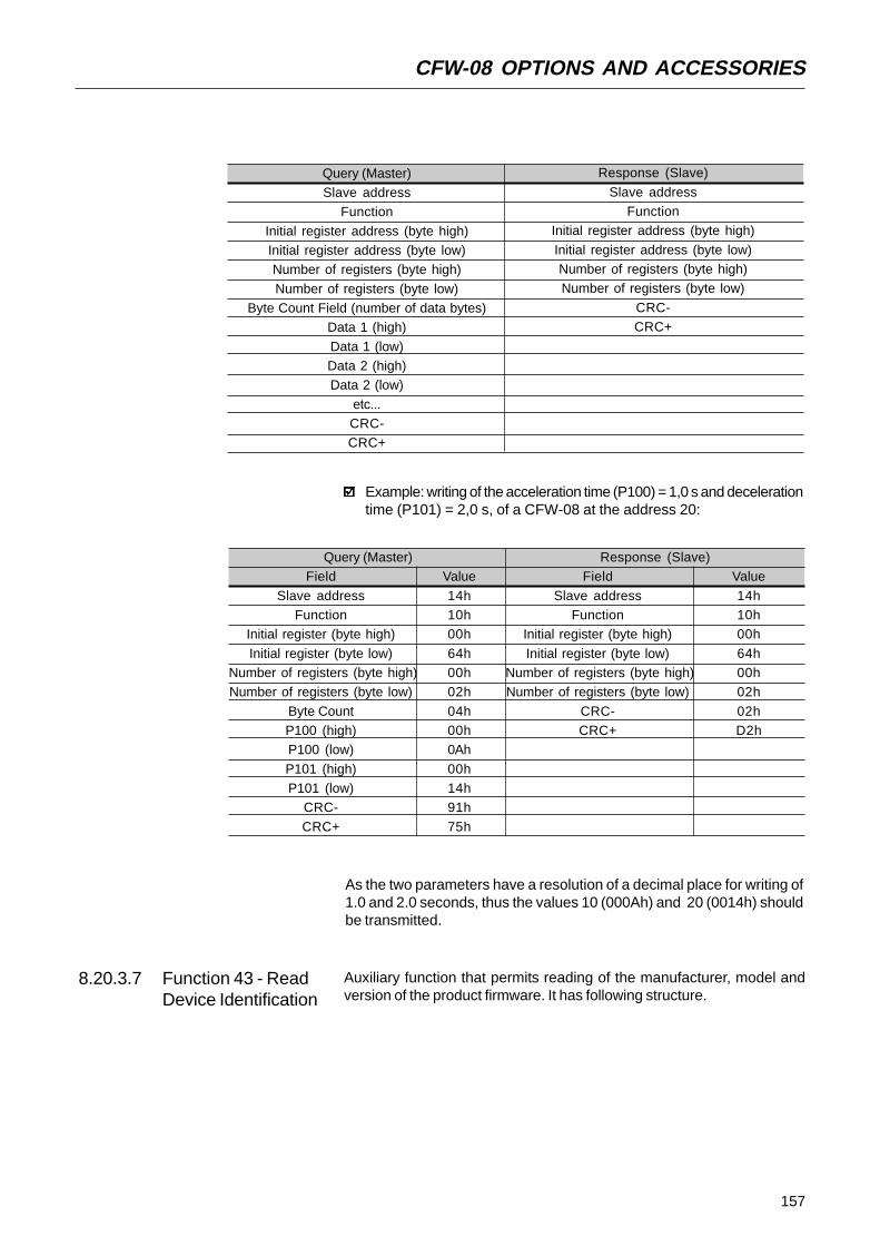
157
CFW-08 OPTIONS AND ACCESSORIES
Query (Master)Slave address
Function
Initial register address (byte high)Initial register address (byte low)Number of registers (byte high)
Number of registers (byte low)Byte Count Field (number of data bytes)
Data 1 (high)
Data 1 (low)Data 2 (high)Data 2 (low)
etc...CRC-CRC+
Response (Slave)
Slave addressFunction
Initial register address (byte high)
Initial register address (byte low)Number of registers (byte high)Number of registers (byte low)
CRC-CRC+
Example: writing of the acceleration time (P100) = 1,0 s and decelerationtime (P101) = 2,0 s, of a CFW-08 at the address 20:
Query (Master)Field Value
Slave address 14hFunction 10h
Initial register (byte high) 00h
Initial register (byte low) 64hNumber of registers (byte high) 00hNumber of registers (byte low) 02h
Byte Count 04hP100 (high) 00hP100 (low) 0Ah
P101 (high) 00hP101 (low) 14h
CRC- 91h
CRC+ 75h
Response (Slave)Field Value
Slave address 14hFunction 10h
Initial register (byte high) 00h
Initial register (byte low) 64hNumber of registers (byte high) 00hNumber of registers (byte low) 02h
CRC- 02hCRC+ D2h
As the two parameters have a resolution of a decimal place for writing of1.0 and 2.0 seconds, thus the values 10 (000Ah) and 20 (0014h) shouldbe transmitted.
8.20.3.7 Function 43 - ReadDevice Identification
Auxiliary function that permits reading of the manufacturer, model andversion of the product firmware. It has following structure.

158
CFW-08 OPTIONS AND ACCESSORIES
Query (Master)Slave address
Function
MEI TypeRead Code
Object Number
CRC-CRC+
Response (Slave)Slave address
Function
MEI TypeConformity Level
More Follows
Next ObjectNumber of Objects
Object Code*
Object length*Object Value*
CRC-
CRC+
The fields are repeated according to the number of objects.This function permits reading of three information categories:Basic, Regular and Extended and each category are formed by a group ofobjects. Each object is formed by a sequence of ASCII characters For theCFW-08 are only available basic information formed by three objects:
Object 00 - VendorName: always ‘WEG’.Object 01 - ProductCode: formed by the product code (CFW-08), plusthe rated inverter current.Object 02 - MajorMinorRevision: it indicates the inverter firmwareversion, in ‘VX.XX’ format.
The read code indicates which information categories are being read andif the objects are accessed individually of by sequence.In the example, the inverter supports 01 (basic information in sequence),and 04 (individual access to the objects).The other fields for the CFW-08 have fixed values.
Example: read o basic information in sequence, starting from object00, of a CFW-08 at address 1:
Query (Master)Field Value
Slave address 01h
Function 2BhMEI Type 0Eh
Read Code 01h
Object Number 00hCRC- 70hCRC+ 77h
Response (Slave)Field Value
Slave address 01h
Function 2BhMEI Type 0Eh
Read Code 01h
Conformity Level 51hMore Follows 00hNext Object 00h
Number of Objects 03hObject Code 00h
Object Length 03h
Object Value ‘WEG’Object Code 01h
Object Length 0Eh
Object Value ‘CFW-08 7.0A’Object Code 02h
Object Length 05h
Object Value ‘V3.77’CRC- C7hCRC+ DEh

159
CFW-08 OPTIONS AND ACCESSORIES
In the example the Object Value has not been represented as hexadecimalvalue, but with corresponding ASCII characters.For instance, for the object 00, the WEG‘ value has been transmitted asbeing three ASCII characters, that as hexadecimal have the values 57h(W), 45h (E) e 47h (G).
8.20.4 Communication Errors Errors can occur during the message transmission on network, or in thecontent of the received messages. Depending on the error type, invertermay answer or not to the master:When the master sends a message to an inverter configured at determinednetwork address, the inverter will not response if:
Error in the parity bit.Error the CRC.Time out between transmitted bytes (3.5 times the time required forthe transmission of a 11-bit word).
In the case of a successful reception of the message, the inverter candetect problems and send a error message to the master indicating theproblem that has been verified:
Invalid function (error code = 1): the requested function has not beenimplemented for the inverter.Invalid data address (error code = 2): the data address (register or bit)does not exist.Data value invalid (error code = 3): this error occurs in the followingconditions:
Value is out of permitted range.Writing in data that cannot be changed (only read register, orregister that does not allow changing with enabled inverter or bitsof logic status).Writing in function of the logic command that has not been enabledvia serial interface.
8.20.4.1 Error Messages When any error occurs in the message content (not during the datatransfer), the slave must return a message indicating the error type thatoccurred. The errors that may occur in the CFW-08 during the messageprocessing are errors relating to invalid function (code 01), invalid dataaddress (code 02) and invalid data value (code 03).The messages sent by the slave have following structure:
Response (Slave)Slave address
Function Code(with most significant bit to 1)
Error code
CRC-CRC+
Master requests from the slave at address 1 to write parameter 89(inexistent parameter):

160
CFW-08 OPTIONS AND ACCESSORIES
Query (Master)Field Value
Slave address 01h
Function 06hRegister (high) 00hRegister (low) 59h
Value (high) 00hValue (low) 00h
CRC- 59h
CRC+ D9h
Response (Slave)Field Value
Slave address 01h
Function 86hError Code 02h
CRC- C3h
CRC+ A1h
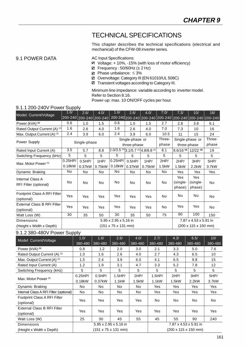
161
TECHNICAL SPECIFICATIONSThis chapter describes the technical specifications (electrical andmechanical) of the CFW-08 inverter series.
9.1 POWER DATA AC Input Specifications:Voltage: + 10%, -15% (with loss of motor efficiency)Frequency : 50/60Hz (± 2 Hz)Phase unbalance: 3%Overvoltage: Category III (EN 61010/UL 508C)Transient voltages according to Category III.
Minimum line impedance: variable according to inverter model.Refer to Section 8.16.Power-up: max. 10 ON/OFF cycles per hour.
≤
CHAPTER 9
9.1.1 200-240V Power SupplyModel: Current/Voltage
Power (kVA) (1)
Rated Output Current (A) (2)
Max. Output Current (A) (3)
Power Supply
Rated Input Current (A)Switching Frequency (kHz)
Max. Motor Power (5)
Dynamic Braking
Internal Class ARFI Filter (optional)
Footprint Class A RFI Filter(optional)External Class B RFI Filter
(optional)Watt Loss (W)Dimensions
(Height x Width x Depth)
1.6/200-240
0.6
1.62.4
3.55
0.25HP/0.18kW
No
No
Yes
Yes
30
2.6/200-240
1.0
2.63.9
5.75
0.5HP/0.37kW
No
No
Yes
Yes
35
4.0/200-240
1.5
4.06.0
8.85
1HP/0.75kW
No
No
Yes
Yes
50
7.3/200-240
2.8
7.311
8.6/16 (4)
5
2HP/1.5kW
Yes
Yes(single-phase)
No
Yes
90
10/200-240
3.8
1015
12/22 (4)
5
3HP/2.2kW
Yes
Yes(single-phase)
No
Yes
100
16/200-240
6.1
1624
195
5HP/3.7kW
Yes
No
No
No
150
7.0/200-240
2.7
7.010.5
8.15
2HP/1.5kW
No
No
No
No
75
5.95 x 2.95 x 5.16 in(151 x 75 x 131 mm)
7.87 x 4.53 x 5.91 in(200 x 115 x 150 mm)
Single-phaseThree-phase
1.6/ 200-240
0.6
1.62.4
2.0/3.5 (4)
5
0.25HP/0.18kW
No
No
Yes
Yes
30
2.6/200-240
1.0
2.63.9
3.1/5.7 (4)
5
0.5HP/0.37kW
No
No
Yes
Yes
35
4.0/200-240
1.5
4.06.0
4.8/8.8 (4)
5
1HP/0.75kW
No
No
Yes
Yes
50
Single-phase orthree-phase
Single-phase orthree-phase
Three-phase
9.1.2 380-480V Power Supply
Model: Current/Voltage
Power (kVA) (1)
Rated Output Current (A) (2)
Max. Output Current (A) (3)
Rated Input Current (A)Switching Frequency (kHz)
Max. Motor Power (5)
Dynamic Braking
Internal Class A RFI Filter (optional)Footprint Class A RFI Filter(optional)
External Class B RFI Filter(optional)Watt Loss (W)
Dimensions(Height x Width x Depth)
1.0/
380-4800.81.0
1.51.25
0.25HP/0.18kW
No
No
Yes
Yes
25
1.6/
380-480 1.21.6
2.41.95
0.5HP/0.37kW
No
No
Yes
Yes
30
2.6/
380-4802.02.6
3.93.15
1.5HP/1.1kW
No
No
Yes
Yes
45
4.0/
380-4803.04.0
6.04.75
2HP/1.5kW
No
No
Yes
Yes
55
2.7/
380-4802.12.7
4.13.35
1.5HP/1.1kW
Yes
Yes
No
Yes
45
4.3/
380-4803.34.3
6.55.25
2HP/1.5kW
Yes
Yes
No
Yes
55
6.5/
380-4805.06.5
9.87.85
3HP/2.2kW
Yes
Yes
No
Yes
90
10/
380-4807.610
15125
5HP/3.7kW
Yes
Yes
No
Yes
2405.95 x 2.95 x 5.16 in(151 x 75 x 131 mm)
7.87 x 4.53 x 5.91 in(200 x 115 x 150 mm)

162
TECHNICAL SPECIFICATIONS
NOTE!(1) The power rating in VA is determined by the following equation:
The values shown in the table were calculated by considering therated inverter current, input voltage of 220V for the 220-240V modelsand input voltage of 440Vfor the 380-480 models.
(2) Rated current is valid for the following conditions:Relative air humidity: 5% to 90%, non condensing.Altitude : 3300 ft (1000m), up to 13200 ft (4000m) with 10%derating/3300 ft (1000m) of the rated current.Ambient temperature: 32º to 104ºF (0...40º C) (up to 122ºF (50ºC)with 2%/ºC derating of the rated current).The rated current values are valid for the switching frequencies of2.5kHz or 5kHz (factory setting). For higher switching frequencies,10kHz and 15kHz, consider the values shown in the description ofthe parameter P297(refer to chapter 6).
(3) Maximum Current:Inverter supports an overload of 50% (maximum output current= 1.5 x the rated output current) during 1 minute for each 10 minutesof operation. For higher switching frequencies, 10kHz and15kHz, consider the values shown at the description of the parameterP297(refer to chapter 6).
(4) Rated input current for single-phase operation.Note: The models CFW080016B2024..., CFW080026B2024...,CFW080040B2024..., CFW080073B2024... and CFW080100B2024...can be operated both with single-phase voltage and three-phase voltagewithout output current derating.
(5) The indicated motor power ratings are only orientative values for IV-polemotors and normal duty loads. The precise inverter sizing mustconsider the actual motor nameplate and application data.
P(kVA)= 3 . Voltage (Volt) . Current (Amp)
1000
7.99 x 5.63 x 6.50 in(203 x 143 x 165 mm)
Model: Current/Voltage
Power (kVA) (1)
Rated Output Current (A) (2)
Max. Output Current (A) (3)
Rated Input Current (A)Switching Frequency (kHz)Max. Motor Power (5)
Dynamic BrakingInternal Class A RFI Filter (optional)External Class B RFI Filter
(optional)Watt Loss (W)Dimensions(Height x Width x Depth)
13/380-480
9.913
19.5
155
7.5HP/5.5kW
YesYes
Yes
150
16/ 380-480
12.2
162419
510HP/7.5kW
Yes
Yes
Yes
240

163
TECHNICAL SPECIFICATIONS
Voltage Source InverterV/F Control or Sensorless Vector Control (VVC - Voltage Vector Control).PWM SVM(Space Vector Modulation).
0 ... 300Hz, resolution of 0.01Hz.
Speed regulation: 1% of the rated speed.
Speed regulation: 0.5% of the rated speed.
CFW-08: 1 isolated input, resolution: 7 bits, 0 to +10V or (0)4 to 20mA,
Impedance: 100k (0 ±10 V), 500 [(0) 4 to 20 mA], progr. functions.CFW-08 Plus: 2 isolated inputs, resolution: 7 bits, 0 to +10V or (0)4to 20 mA, Impedance: 100k (0 a +10V), 500 [(0) 4 to 20 mA],
programmable functions.4 isolated digital inputs, 12Vdc, programmable functionsCFW-08 Plus: 1 isolated output, 0 a +10V, RL 10k (max. load.), resolution:
8 bits, programmable functionsCFW-08: 1 relay with reverse contacts, 240VAC, 0.5A, programmablefunctions
CFW-08 Plus: 2 relays, one with NO contact and one with NC contact.It can be programmed to operate as 1 reverse, 240VAC, 0.5A,programmable functions
Overcurrent/output short-circuitOutput groung faultDC link under/overvoltage
Inverter overtemperatureMotor/inverter overload (IxT)External fault
Programming errorSelf-tuning errorDefective inverter
8 keys: start, stop, increment, decrement, FWD/REV, JOG,local/remote and programmingLEDs display: 4 digits with 7 segments
LEDs for FWD/REV andLOCAL/REMOTE indicationIt permits access/alteration of all parameters
Display accuracy: - current: 10% of the rated current
- speed resolution: 1 rpm
- frequency resolution: 0.01HzModels 13 and 16A/380-480V; other models with KN1-CFW08-M1and KN1-CFW08-M2 kits.
All models without KN1-CFW08-M1 or KN1-CFW08-M2 kit.Exception: Models 13 and 16A/380-480V.Inverters and semicondutorsPower Conversion EquipmentElectronic equipment for use in power installationsSafety requirements for electrical equipment for measurement,control and laboratory useEMC product standard for adjustable speed electrical power drive systems
CONTROLMETHOD
OUTPUT
FREQUENCY
PERFORMANCEV/F CONTROL
VECTOR
CONTROL
INPUTS ANALOG
(Control Board
ECC2)
DIGITAL
OUPUTS
ANALOG
(Control Board)RELAY
SAFETY PROTECTION
KEYPADSTANDARD
(HMI-CFW-08-P)(HMI)
DEGREE OFNEMA1 / IP20
PROTECTION PROTECTED CHASSIS /
IP20IEC 146
UL 508 C
STANDARDS EN 50178
EN 61010
EN 61800-3
9.2 ELECTRONICS/GENERAL DATA
Ω
Ω
Ω
Ω
≥

164
TECHNICAL SPECIFICATIONS
The inverters are delivered with factory setting to drive WEG three-phase,IV-pole, IP55 motors, frequency of 60Hz, voltage of 220V for 200-240Vmodels or 380V for 380-480V modelS and with power as indicated in theTables of Sections 9.1.1 and 9.1.2.The data of the applied motor must be programmed at P399 to P409 andthe value of P409 (stator resistance) obtained through the Self-Tuning(parameter estimation via P408).The table below shows the data of WEG standard motors as a reference.
9.3 WEG STANDARD IV POLEMOTOR DATA
NOTES!(*)
The inverter considers the value of the stator resistance as the motorhas been always star-connected, independently of its connection inthe terminal box.The values of the stator resistance is a mean value per phase considering the motors with temperature rise ( T) of 100oC.
Power [P404]
(HP) (kW)
0.16 0.120.25 0.180.33 0.25
0.5 0.370.75 0.551.0 0.75
1.5 1.102.0 1.503.0 2.20
4.0 3.005.0 3.706.0 4.50
0.16 0.120.25 0.180.33 0.25
05 0.370.75 0.551.0 0.75
1.5 1.102.0 1.503.0 2.20
4.0 3.005.0 3.706.0 4.50
75 5.5010 7.50
12.5 9.20
Frame
636363
717180
8090S90L
100L100L112M
636363
717180
8090S90L
100L100L112M
112M132S132M
Current[P401]
(Amp)
0.851.121.42
2.072.903.08
4.786.478.57
11.613.816.3
0.490.650.82
1.201.671.78
2.763.744.95
6.707.979.41
11.4915.1818.48
Efficiency at rated load
η [P399](%)
56.064.067.0
68.071.078.0
72.780.079.3
82.784.684.2
56.064.067.0
68.071.078.0
72.780.0793
82.784.684.2
88.589.087.7
Power Factor atrated load
cosϕ[P407]
0.660.660.69
0.690.700.82
0.830.760.85
0.820.830.86
0.660.660.69
0.690.700.82
0.830.760.85
0.820.830.86
0.820.840.86
StatorResistance (*)
[P409]
(Ω)
21.77
14.8710.637.37
3.974.132.78
1.550.990.65
0.490.38
65.30
44.6031.9022.10
11.9012.408.35
4.652.971.96
1.471.150.82
0.680.47
Voltage[P400]
(V)
220
380
Freq.[P403]
(Hz)
60
60
Speed[ P402 ](rmp)
1720
172017201720
172017301700
1720171017301730
173017201720
172017201720
173017001720
171017301730
173017401760
1755
165
WARRANTY
WEG warrants its Frequency Inverters against defects in workmanshipand materials under the following conditions:
1.0 For the effectiveness of this warranty it is essential that the purchaserinspects carefully the purchased inverter, immediately after receipt,checking its characteristics and following its installation, adjustments,operation and maintenance instructions. The inverter will be consideredas accept and approved automatically by the purchaser, when thepurchaser does not give written notice within max. five days after thereceipt of the product about verified non-conformities.
2.0 The warranty period is for twelve months from the invoice date of theequipment issued by WEG or its authorized distributor, proved throughequipment invoice, but limited to twenty four months from themanufacturing date, that is indicated on the product nameplate.
3.0 In case the inverter fails to function or operate incorrectly during thewarranty time, the warranty services will be carried out, at WEGdiscretion, at its Authorized Repair Shops.
4.0 The failed product must be available to the supplier for a requiredperiod to detect the cause of the failure and to make the correspondingrepairs.
5.0 WEG Automação, or its Authorized Repair Shops will analyze thereturned inverter and when the existence of the failure covered bythe warranty is proved, it will repair, modify or replace, at its discretion,the defective inverter without cost to the purchaser, except asindicated in Item 7.0.
6.0 The present warranty responsibility is limited only to repairs, changesor replacement of the supplied inverter. WEG will have no obligationor liability whatsoever to people, third parties, other equipment orinstallations, including without limitation, any claims for loss of profits,consequential damages or labor costs.
7.0 Other expenses as freights, packing, disassembling/assembling andparameter setting costs will be paid exclusively by the purchaser,including all fees, ticket, accommodation and meals expenses fortechnical personnel, when needed and/or requested by the customer.
8.0 The present warranty does not cover the normal wear of the productor equipment, neither damages resulting from incorrect or negligentoperation, incorrect parameter setting, improper maintenance orstorage, operation out the technical specification, bad installationquality, or operated in ambient with corrosives gases or with harmfulelectrochemical, electrical, mechanical or atmospheric influences.
WARRANTY TERMS FOR FREQUENCY INVERTERSCFW-08
CHAPTER 10

166
WARRANTY
9.0 This warranty does not cover parts or components that areconsidered consumer goods, such as rubber or plastic parts,incandescent bulbs, fuses, etc.
10.0 This warranty will be cancelled automatically, independently ofany previous written notice or not, when the purchaser , withoutprevious written authorization by WEG, makes or authorized thirdparties to make any changes or repair on the product or equipmentthat failed during the warranty period.
11.0 Repairs, changes, or replacements due to manufacturing defectswill not stop nor extend the period of the existing warranty.
12.0 Any request, complaint, communication, etc. related to the productunder warranty, servicing, start-up, etc., shall be sent in writing toWEG Branch or Representative.
13.0 The Warranty granted by WEG is conditioned by the observationof this warranty that is the only valid warranty for the good.