vector logger configurator€¦ · 2.8 filter 16 2.9 memory media ... 2.13 ccp/xcp 20 ... with the...
TRANSCRIPT

User Manual
Vector Logger Configurator
Version 2.7 English

Imprint Vector Informatik GmbH Ingersheimer Straße 24 D-70499 Stuttgart Vector reserves the right to modify any information and/or data in this user documentation without notice. This documentation nor any of its parts may be reproduced in any form or by any means without the prior written consent of Vector. To the maximum extent permitted under law, all technical data, texts, graphics, images and their design are protected by copyright law, various international treaties and other applicable law. Any unauthorized use may violate copyright and other applicable laws or regulations. © Copyright 2017, Vector Informatik GmbH. Printed in Germany. All rights reserved.

User Manual Vector Logger Configurator Contents
© Vector Informatik GmbH Version 2.7 - I -
Contents
1 Introduction 3
1.1 Vector Logger Configurator Overview 4 1.2 About this User Manual 5
1.2.1 Certification 6 1.2.2 Warranty 6 1.2.3 Support 6 1.2.4 Trademarks 6
2 Overview 7
2.1 General Information 8 2.2 LED Display and Keys 8 2.3 Ring Buffer 9 2.4 Triggered Logging 10
2.4.1 GL Logger 10 2.4.2 VN1630 log 11
2.5 Long-Term Logging 12 2.6 Operating Mode 15
2.6.1 GL Logger 15 2.6.2 VN1630 log 15
2.7 Data Compression 16 2.8 Filter 16 2.9 Memory Media 16 2.10 Download and Upload 17
2.10.1 GL1000/GL2000 Series 17 2.10.2 GL3000/GL4000 Series 17 2.10.3 VN1630 log 18 2.10.4 Logging Formats 18 2.10.5 Automated Sequences 19
2.11 Navigator versus Classic View 19 2.12 Pack&Go 19 2.13 CCP/XCP 20 2.14 Diagnostics 23 2.15 Monitoring Interface 25
2.15.1 Monitoring Mode 25 2.15.2 Signal Sampling Mode 27
3 Vector Logger Configurator 29
3.1 Installation Instructions 30 3.2 Overview 30 3.3 Tree View 31
3.3.1 Hardware 31 3.3.2 General 32 3.3.3 Logging Memory 32 3.3.4 CCP/XCP 32 3.3.5 Diagnostics 32 3.3.6 Output 33

User Manual Vector Logger Configurator Contents
© Vector Informatik GmbH Version 2.7 - II -
3.3.7 File Manager 33 3.4 Property Panel 34 3.5 Toolbar 34
3.5.1 Real-Time Clock 34 3.5.2 Refresh 34 3.5.3 Representation Dec/Hex 35 3.5.4 Conversion Profiles 35
3.6 General Settings 35
4 Tutorial 37
4.1 Overview 38 4.2 Tutorial 1: Create a Configuration 38 4.3 Tutorial 2: Download Configuration (GL1000/GL2000 Series) 39 4.4 Tutorial 3: Upload and Convert Logged Data (GL1000/GL2000 Series) 40 4.5 Tutorial 4: Download Configuration (GL3000/GL4000 Series) 40 4.6 Tutorial 5: Upload and Convert Logged Data (GL3000/GL4000 Series) 41 4.7 Tutorial 6: Read out and Download via USB (GL3000/GL4000 Series) 41 4.8 Tutorial 7: Download Configuration (VN 1630 log) 43 4.9 Tutorial 8: Upload and Convert Logged Data (VN1630 log) 43 4.10 Tutorial 9: Configuration with Simple Filter 44 4.11 Tutorial 10: Configuration with Simple Trigger 44 4.12 Tutorial 11: CCP/XCP und Seed & Key (GL Logger) 45
4.12.1 Creation of Configuration 45 4.12.2 Generation of an SKB File 46 4.12.3 Installation of a CCP/XCP License 48
4.13 Tutorial 12: CCP/XCP and Seed & Key with CANape (GL Logger) 49 4.13.1 Generation of a DBC File 49 4.13.2 Generation of a FIBEX File 50 4.13.3 Creation of the Logger Configuration 51
4.14 Tutorial 13: Usage as Interface (GL2000/GL3000/GL4000 Series) 52 4.14.1 Configuration of the Logger 52 4.14.2 Configuration in CANoe/CANalyzer 52
4.15 Tutorial 14: Logging of Diagnostic Data (GL Logger) 54 4.16 Tutorial 15: Configuration of the 3G Data Transmission (GL2000 Series) 55
4.16.1 Configuration of the Logger 55 4.16.2 Connections and Displays of the Sierra Wireless AirLink LS300 55 4.16.3 Configuration of the 3G Router 57
4.17 Tutorial 16: Record images with a HostCAM (GL3000/GL4000 Series) 59 4.17.1 Setting up the HostCAM 60 4.17.2 Configuration of a Triggered Capturing 61 4.17.3 Configuration of a Long-term Capturing 63
5 Index 65

User Manual Vector Logger Configurator Introduction
© Vector Informatik GmbH Version 2.7 - 3 -
1 Introduction
In this chapter you find the following information:
1.1 Vector Logger Configurator Overview page 4
1.2 About this User Manual page 5 Certification Warranty Support Trademarks

User Manual Vector Logger Configurator Introduction
© Vector Informatik GmbH Version 2.7 - 4 -
1.1 Vector Logger Configurator Overview
Vector Logger Configurator
The Vector Logger Configurator is a tool to create easy configurations for the compact loggers of the GL1000/GL2000 series and the multibus logger of the GL3000/GL4000 series. Additionally it is already prepared for the logging functionality of the VN1630 log interface when operating in standalone mode.
With the Vector Logger Configurator hardware settings for CAN, LIN, FlexRay and MOST150 channels can be set. Filter and trigger conditions, logging of analog and digital inputs, diagnostic data and CCP/XCP measurements can be configured. Additionally LEDs can be set to visualize certain events. The settings depend on the device type.
Readout of the logging data is supported as well as conversion to several logging formats.
Screenshot

User Manual Vector Logger Configurator Introduction
© Vector Informatik GmbH Version 2.7 - 5 -
1.2 About this User Manual
To find information quickly
The user manual provides you the following access helps: > At the beginning of each chapter you will find a summary of the contents, > In the header you can see the current chapter and section, > In the footer you can see to which version the user manual replies, > At the end of the user manual you will find an index.
Conventions In the two following charts you will find the conventions used in the user manual regarding utilized spellings and symbols.
Style Utilization bold Blocks, surface elements, window- and dialog names of the
software. Accentuation of warnings and advices. [OK] Push buttons in brackets File|Save Notation for menus and menu entries
Windows Legally protected proper names and side notes. Source code File name and source code. Hyperlink Hyperlinks and references. <STRG>+<S> Notation for shortcuts. Symbol Utilization
Here you can obtain supplemental information.
This symbol calls your attention to warnings.
Here you can find additional information.
Here is an example that has been prepared for you.
Step-by-step instructions provide assistance at these points.
Instructions on editing files are found at these points.
This symbol warns you not to edit the specified file.

User Manual Vector Logger Configurator Introduction
© Vector Informatik GmbH Version 2.7 - 6 -
1.2.1 Certification
Certified Quality Management System
Vector Informatik GmbH has ISO 9001:2008 certification. The ISO standard is a globally recognized standard.
1.2.2 Warranty
Restriction of warranty
We reserve the right to modify the contents of the documentation or the software without notice. Vector disclaims all liabilities for the completeness or correctness of the contents and for damages which may result from the use of this documentation.
1.2.3 Support
You need support? You can get through to our hotline at the phone number
+49 711 80670-200
or you write an email to [email protected].
1.2.4 Trademarks
Protected trademarks
All brand names in this documentation are either registered or non registered trademarks of their respective owners.

User Manual Vector Logger Configurator Overview
© Vector Informatik GmbH Version 2.7 - 7 -
2 Overview
In this chapter you find the following information:
2.1 General Information page 8
2.2 LED Display and Keys page 8
2.3 Ring Buffer page 9
2.4 Triggered Logging page 10 GL Logger VN1630 log
2.5 Long-Term Logging page 12
2.6 Operating Mode page 15 GL Logger VN1630 log
2.7 Data Compression page 16
2.8 Filter page 16
2.9 Memory Media page 16
2.10 Download and Upload page 17 GL1000/GL2000 Series GL3000/GL4000 Series VN1630 log Logging Formats Automated Sequences
2.11 Navigator versus Classic View page 19
2.12 Pack&Go page 19
2.13 CCP/XCP page 20
2.14 Diagnostics page 23
2.15 Monitoring Interface page 25 Monitoring Mode Signal Sampling Mode
User Manual Vector Logger Configurator Overview
© Vector Informatik GmbH Version 2.7 - 8 -
2.1 General Information
Logger The Vector Logger Configurator allows the configuration of the loggers of the GL1000/GL2000/GL3000/GL4000 series and for the logging functionality of the VN1630 log interface. The following sections describe the hardware specific features of the loggers.
2.2 LED Display and Keys
LED display GL1000 series
The logger has five LEDs. LED 1 to LED 4 are freely programmable. The LEDs can be assigned to different events like trigger active or CAN/LIN errors. LED USB indicates the connection to the PC and is not programmable. Please refer to the User Manual GL1000/GL1010 for more details about the meaning of this LED.
LED display GL2000 The logger has six LEDs. LED 1 to LED 4 are freely programmable. The LEDs can be assigned to different events like trigger active or CAN/LIN errors. LED USB indicates the connection to the PC, and LED Power the status of the power supply. These two LEDs are not programmable. Please refer to the User Manual GL2000 for more details about the meaning of this LED.
LED display GL3000/GL4000 series
The logger has five red LEDs that are freely programmable. The LEDs can be assigned to different events like trigger active or CAN/LIN/FlexRay errors.
LED display VN1630 log
The VN1630 log has five LEDs indicating bus activities and status as well as one LED for the logging mode. The LEDs are not configurable.
Please refer to the user manual of the VN16000 interface family for more details about the meaning of the LEDs.
Event keys GL3000/GL4000 series
The GL3100/GL3200 and the GL4000 series loggers feature four programmable event buttons on the front panel. These buttons can be used as triggers, for example.

User Manual Vector Logger Configurator Overview
© Vector Informatik GmbH Version 2.7 - 9 -
2.3 Ring Buffer
Concept A ring buffer is a certain memory area where logging data is stored. If the end of this memory area is reached, the oldest data from the beginning of the area is overwritten. Thus, the ring buffer contains always the latest logged data.
GL1000/GL2000 series
The ring buffer sizes can be configured between 2 MB and 2 GB. The ring buffer is directly written on the SD card, not in the RAM of the logger.
GL3000/GL4000 series
The GL3000/GL4000 series contains two ring buffers (memory 1 and memory 2) in the RAM that can be configured independently. The size of each ring buffer can be set between 1 MB and 117 MB (GL3000 series) or 234 MB (GL4000 series). The sum of the two ring buffers (Memory1_Block1 + Memory2_Block1) must not exceed 117 MB or 234 MB. The ring buffer is created in the RAM of the logger and written to the memory medium when a trigger occurs.
GL Logger Every ring buffer is installed twice, that means in block 1 and block 2. While the saving process of the data of one ring buffer block to the memory medium the new data is written to the other ring buffer block. With this procedure no data loss occurs while saving the data of a ring buffer block.
VN1630 log The ring buffer is installed on the RAM of the device with the size of 32 MB. The maximum size of the logging file is configurable.
Data is written to the memory when a trigger occurs. At a permanent long-term logging data are buffered shortly and afterwards written to the memory card.

User Manual Vector Logger Configurator Overview
© Vector Informatik GmbH Version 2.7 - 10 -
2.4 Triggered Logging
2.4.1 GL Logger
Concept If a certain event occurs, writing to the ring buffer is stopped. This event is called a trigger. When a trigger event occurs the ring buffer is closed, i.e. data storage to the ring buffer is stopped and the data in the ring buffer is stored as a triggered file. New logging data is stored to a new empty ring buffer.
The ring buffer can be configured to continue logging for a defined post-trigger time after the trigger event. In this case, the ring buffer is not closed when the trigger event occurs, but after the post-trigger time.
This trigger behavior applies to the Triggered Logging mode. With the Conditioned long-term logging mode trigger types are used which directly start and stop the data logging.
If a trigger event occurs after just a brief time and the end of the ring buffer has not
yet been reached, the logging file will be smaller than the specified ring buffer size. If a trigger event occurs after a longer time, i.e. the data in the ring buffer have been overwritten one or more times, the size of the logging file corresponds to that of the ring buffer.
Various trigger events can be defined and parameterized in the Vector Logger Configurator, e.g. on receiving a certain message or if a certain value in a signal is reached.
The trigger concept saves a lot of memory space, since data doesn’t need to be recorded over all of the time, but only on events of interest.
Triggered logging In order to use triggers for logging the logging mode must be set to Triggered logging. Closed (also called “triggered”) ring buffers are stored as a log file. At the end of the logging session an open ring buffer may remain. This open ring buffer is stored to a log file, too.
Pre-trigger time The pre-trigger time describes the time to be recorded before a trigger event.

User Manual Vector Logger Configurator Overview
© Vector Informatik GmbH Version 2.7 - 11 -
Post-trigger time The post-trigger time describes the time to be recorded after a trigger event. After the post-trigger time elapses the current ring buffer is closed and a new ring buffer is started.
The Vector Logger Configurator supports the configuration of the post-trigger time
only. The pre-trigger time results from the rest of the ring buffer which is recorded before the trigger occurred. A calculator is available for the estimation of the needed ring buffer size.
2.4.2 VN1630 log
Concept If a certain trigger event occurs, data from the ring buffer is written to the memory card according to the set pre-trigger-time. Afterwards data is written for the duration of the post-trigger time to the same file. Data is stored as a triggered file. New logging data is stored to ring buffer until the next trigger.
Various trigger events can be defined and parameterized in the Vector Logger Configurator, e.g. on receiving a certain message or if a certain value in a signal is reached.
The trigger concept saves a lot of memory space, since data doesn’t need to be recorded over all of the time, but only on events of interest.
Triggered logging In order to use triggers for recording the logging mode must be set to Triggered logging. Triggered ring buffers are stored as a log file. At the end of the logging session an open ring buffer may remain. This open ring buffer is not stored to a log file.
Pre-trigger time The pre-trigger time describes the time to be recorded before a trigger event. If a trigger event occurs after just a brief time and the pre-trigger time has not been reached, the logging file therefore contains less data accordingly.
Post-trigger time The post-trigger time describes the time to be recorded after a trigger event. After the post-trigger time elapses the current logging file ring buffer is closed. New data is written to the ring buffer again.
The Vector Logger Configurator supports the configuration of the post-trigger time only. The pre-trigger time is limited by the size of the RAM. A calculator is available for the estimation whether the RAM size is big enough for the wanted pre-trigger time. If during the recording the RAM is faster filled up than expected, e.g. the bus load is higher than expected, the oldest data is deleted and thus the pre-trigger time shortened.

User Manual Vector Logger Configurator Overview
© Vector Informatik GmbH Version 2.7 - 12 -
2.5 Long-Term Logging
Permanent long-term logging
Alternative to recordings with triggers you can record the complete data traffic from measurement start continuously in a permanent long-term logging without gaps. Therefore the logging mode is set to Permanent long-term logging. In this mode all configured triggers are switched off.
GL Logger In order to record the data traffic without gaps, ring buffers are still used internally. As soon as the ring buffer is completely filled, it is triggered and the recording is immediately continued to the next ring buffer without gaps. For permanent long-term logging the Vector Logger Configurator uses the configured ring buffer size. The post-trigger time is not used. Permanent long-term logging is a chain of ring buffers without gap. Due to this the File Manager of the Vector Logger Configurator displays the logging data not as one big file per test-drive but as many single files each of the same ring buffer size.
If the logger changes to sleep mode, the current ring buffer will be triggered in advance even if the buffer was not completely full. The file is marked as end of test-drive and will be stored. At the next logger start, a new ring buffer is started.
At read out and conversion in the File Manager the Vector Logger Configurator identifies that a permanent long-term logging was done and assembles all single files of a test-drive that were logged between switching on and off of the logger (or sleep/wake up) to one big file for that test-drive.
With the Separate files for each ring buffer option it is possible to read out the
logged data in single files per ring buffer. This option makes it easier to analyze the logging data if needed.
VN1630 log Data traffic is recorded continuously. As soon as the defined maximum size of the file is reached the recording is immediately continued to the next logging file without gaps. The Vector Logger Configurator displays in the File Manager the individual logging files.

User Manual Vector Logger Configurator Overview
© Vector Informatik GmbH Version 2.7 - 13 -
Conditioned long-term logging
Alternatively the permanent long-term logging of the data traffic can be started with a start condition (logging on) and stopped with a stop condition (logging off). For that the logging mode is switched to Conditioned long-term logging.
For each memory only one start trigger and one stop trigger can be configured. After one of these triggers occurred it is inactive until its counterpart is activated.
GL Logger As for the permanent long-term logging, for the logging ring buffers are still used internally. As soon as the ring buffer is completely filled, it is triggered and the recording is immediately continued to the next ring buffer without gaps. For this the Vector Logger Configurator uses the configured ring buffer size. The post-trigger time is not used. The File Manager of the Vector Logger Configurator displays the logging data not as one big file per logging block but as many single files each of the same ring buffer size.
If the logger changes to sleep mode while logging (after logging on), the current ring buffer is triggered even if the buffer was not completely full and the logging off condition was not fulfilled. The file is marked as end of the logging (same as for logging off) and will be stored. At the next logger start the logging on condition must be fulfilled before a new logging will be started.
At read out and conversion in the File Manager the Vector Logger Configurator identifies that a permanent long-term logging (conditioned long-term logging) was done and assembles all single files of each logging block between logging on and logging off to one big file per logging block.
With the Separate files for each ring buffer option it is possible to read out the data
in single files per ring buffer. This option makes it easier to analyze the logging data if needed.
VN1630 log As for the permanent long-term logging, data is recorded continuously in single files. Recording is started with the condition logging on and stopped with the condition logging off.

User Manual Vector Logger Configurator Overview
© Vector Informatik GmbH Version 2.7 - 14 -
Note for GL1000: The logger writes the data directly to the memory card. When the logger is disconnected from power during recording, the last ring buffer is not lost, but the marker for the end of logging (permanent long-term logging or conditioned long-term logging) gets lost. The logger will identify the power interruption at the next start and will add the marker. Thus in spite of the power interruption, the assembly of the single ring buffers per test-drive/logging block is possible because the Vector Logger Configurator requires the end markers to identify and separate the test drives/logging blocks on conversion.
Note for GL2000: The logger writes the data directly to the memory card. When the logger is disconnected from power during recording, the USV provides for a few seconds that the data of the last ring buffer is logged completely. The marker for the end of logging (permanent long-term logging or conditioned long-term logging) is also stored. So the assembly of the single ring buffers per test-drive/logging block is possible in the Vector Logger Configurator.
Note for GL3000/GL4000: When the logger is disconnected from power during recording, the last ring buffer is not saved from the RAM to the memory card. Thus the data from the last ring buffer is lost.
At a permanent long-term logging (permanent long-term logging or conditioned long-term logging) the marker for the end of logging gets lost too. The assembly of the single ring buffers per test-drive/logging block is no longer possible because the Vector Logger Configurator requires the end markers to identify and separate the test drives/logging blocks on conversion.
Please make sure that the GL3000/GL4000 went to sleep before disconnecting power. Alternatively you can open the front panel while the logger is still supplied by power to force a regular shutdown and writing of the last ring buffer to the memory card.
Marker For GL2000/GL3000/GL4000 markers are available. Like triggers, markers are defined for certain events when the logger is configured. However, they do not trigger a new recording (trigger file) but merely mark a point in time within a long-term logging. As a result, you have more flexibility in the selection of pre- and post-trigger time for the readout. However, the long-term logging causes more memory space to be occupied on the memory card.
Markers are only available in the Navigator and help you to quickly locate for the conversion the time areas of interest.

User Manual Vector Logger Configurator Overview
© Vector Informatik GmbH Version 2.7 - 15 -
2.6 Operating Mode
2.6.1 GL Logger
Operating mode The loggers have two operating modes for handling the situation of a full memory medium: > Stop logging mode > Overwrite mode
The operating modes apply to all logging modes (Triggered logging, Conditioned long-term logging and Permanent long-term logging).
Stop Logging mode With the setting Stop logging the logger records data until the memory medium is full. On full memory medium, no further trigger and no logging condition will be considered. This avoids overwriting recorded triggered files on the memory medium.
Overwrite mode With the setting Overwrite oldest the logger records data in ring buffers until the memory medium is full. On full memory card, the oldest triggered file is deleted and the new data is stored. This mode allows keeping always the newest log files on the memory medium while oldest log files are overwritten. Overwrite mode is the default setting for a new configuration in the Vector Logger Configurator.
Logging modes The following figure visualizes the differences between the logging modes: > Stop logging – after „log file n“ the logging is cancelled. > Overwrite oldest – further logging files (log file n+1 etc.) are written on the
memory medium.
2.6.2 VN1630 log
Operating mode The VN1630 log records data until the memory card is full. This avoids overwriting recorded files.
This operating mode applies to all logging modes (Triggered logging, Conditioned long-term logging and Permanent long-term logging).

User Manual Vector Logger Configurator Overview
© Vector Informatik GmbH Version 2.7 - 16 -
2.7 Data Compression
GL3000/GL4000 series
The GL3000/GL4000 series supports the optional compression of the logging files to save space on the memory card. In the same way the transmission time at the read out via WLAN/3G can be reduced. After the read out of the memory card with the File Manager the files will be decompressed automatically.
2.8 Filter
Concept With the Vector Logger Configurator you can use filter on CAN messages, LIN messages and FlexRay frames/PDUs to reduce the amount of logged data. Due to this the possible logging time is extended. The different filters influence the recording of messages only. Messages with Stop filter are not recorded. Messages with Limit filter (GL Logger only) are logged with reduced rate. All other messages are completely stored. The filters do not influence the trigger, because the logger receives all messages. After reception of a message the trigger conditions are checked. A message can cause a trigger even if it is not recorded due to a Stop filter.
2.9 Memory Media
GL1000/GL1010 The GL1000/GL1010 uses an SD/SDHC card for storing logging data. For more information about supported SD/SDHC cards please see the user manual of the GL1000/GL1010.
Info: Please do not remove or exchange the SD/SDHC card in the GL1000/GL1010 during operation in the logging mode. This may cause loss of data!
GL2000 The GL2000 uses an SD/SDHC card for storing logging data. For more information about supported SD/SDHC cards please see the user manual of the GL2000.
GL3000/GL3100/ GL4000
The GL3000/GL3100/GL4000 saves the logging data to a Compact Flash card (CF card). The slot for the Compact Flash card is located behind the front access panel. Alternatively an USB memory medium can be connected.
GL3200/GL4200 The GL3200/GL4200 saves the logging data on a removable disk (SSD). The slot therefore is located behind the front access panel.
VN1630 log The VN1630 log uses an SD/SDHC card for storing logging data. For more information about supported SD/SDHC cards please see the user manual of the VN1600 interface family.

User Manual Vector Logger Configurator Overview
© Vector Informatik GmbH Version 2.7 - 17 -
Memory size Please note that the listed capacity of the CF/SD cards (e.g. 2 GB) may not match the actual available memory size. Some parts of the memory card are used for administration and other functions. The listed capacity printed on the memory medium is calculated with 1 GB = 1 billion bytes, 1 MB = 1 million bytes. This calculation differs from the common calculation in Windows with 1 GB = 1024 MB, 1 MB = 1024 KB, 1 KB = 1024 Byte. This formula known from Windows is also used in the Vector Logger Configurator for the calculation of the available card memory.
2.10 Download and Upload
2.10.1 GL1000/GL2000 Series
Download The configuration can be loaded to the GL1000/GL1010/GL2000/GL2010 by USB interface. Therefore the logger must be connected to the USB port of the PC. Alternatively the configuration can be stored to an SD card in a card reader. In both cases the configuration is stored to the SD card first and will be updated in the logger on the next start in logging mode. If the configuration is updated on start of the logger, the effective start-up time (the time from power-up until recording of the first data frame) is extended.
Upload The Vector Logger Configurator allows the upload of recorded logging data from the logger or SD card of the PC.
For uploading the logging data from the logger, the logger must be connected to the USB port of the PC. The data is uploaded in a raw format first, and automatically converted to the desired logging format afterwards.
For more information about the upload of logging data please see section 3.3.7 File Manager.
2.10.2 GL3000/GL4000 Series
Download GL3000/GL3100/ GL4000
The configuration is saved for the GL3000/GL3100/GL4000to a Compact Flash card in the card reader. This card is then inserted into the logger.
The logger supports a download also via USB (USB port located behind the front access panel). Therefore the logger has to be switched on.
The front access panel must then be closed. The next time the logger is started in logging mode, the configuration is checked and updated if it is okay.
Please refer to
Tutorial 5: Upload and Convert Logged Data (GL3000/GL4000 Series) in section 4.6 and the online help for more information about configuration download.
Upload GL3000/GL3100/ GL4000
The Vector Logger Configurator supports the readout of the recorded data from the Compact Flash card in the card reader. The data is read out in raw format and then converted automatically to the desired logging format.
The logger supports the data read out also via USB (USB port located behind the front access panel). Therefore the logger has to be switched on.

User Manual Vector Logger Configurator Overview
© Vector Informatik GmbH Version 2.7 - 18 -
Download GL3200/GL4200
The configuration for the GL3200/GL4200 is saved to a removable disk (SSD) that is connected to the eSATA interface (with external power supply) on the PC. It is then inserted into the logger. The front access panel must then be closed. The next time the logger is started in logging mode, the configuration will be checked and, if okay, updated.
Upload GL3200/GL4200
The Vector Logger Configurator supports readout of recorded data from the SSD connected to the PC. The data are read out in raw format and then converted automatically to the desired logging format.
2.10.3 VN1630 log
Download The configuration can be loaded to the SD card in the VN1630 log by USB interface. Therefore the device must be connected to the USB port of the PC. Alternatively the configuration can be stored to an SD card in a card reader. In both cases the configuration is stored to the SD card. On each start of the device in logging mode, the configuration is read from the SD card. Please note, that recording can only be started with a configuration on the inserted SD card.
Upload The Vector Logger Configurator allows the configuration of the device and the upload of recorded data from the device or memory card to the PC.
For uploading the logging data from the VN1630 log, it must be connected to the USB port of the PC. The data is uploaded in a raw format first, and automatically converted to the desired logging format afterwards.
For more information about the upload of logging data please see section 3.3.7 File Manager.
2.10.4 Logging Formats
Overview The logged data can be converted to the following formats. Formats GL1000 GL2000 GL3000/GL4000 VN1630 log ASC Yes Yes Yes Yes BLF Yes Yes Yes Yes MDF MDF versions 2.0 to 4.1 1 MDF 4.1 2 IMG No No Yes No TXT Yes Yes Yes No CLF Yes Yes Yes No MAT 3 Yes Yes Yes No HDF5 Yes Yes Yes No
1 signal-oriented 2 message-oriented 3 MALTLAB® v7.3

User Manual Vector Logger Configurator Overview
© Vector Informatik GmbH Version 2.7 - 19 -
2.10.5 Automated Sequences
GL Logger The option exists for all GL Loggers to use the Win32 console program CLexport, for example, to convert the recorded raw data for automated sequences. This program is included in the installation directory of the Vector Logger Configurator. CLexport and other Win32 console programs are described in detail in the user manual of the G.i.N. Configuration Program.
2.11 Navigator versus Classic View
Overview The File Manager enables logging files on memory cards and the SSD to be displayed, transferred to the PC, and converted to the various formats with the selected settings. The settings can be stored in conversion profiles.
The classic view is available for all GL Loggers and VN1630 log. For the GL2000/GL3000/GL4000 series, the Navigator is additionally available.
Classic View When conversion is carried out in this view, all logging files are always transferred from the memory medium to the PC and then converted to the selected format. The logging files can be additionally saved as a raw file on the PC. This gives you the option of converting data from this format to other formats at a later time.
Navigator With the Navigator, you can have more information on the recorded logging data displayed before the conversion is carried out. You thus get a quick overview of the number of messages that were recorded over a particular time period.
In addition, you can use the Navigator to make a targeted selection of the data to be read out. You do not have to read out the entire memory card but can limit the readout to the areas of interest. Markers will help you to quickly locate the time ranges of interest. By including less data, the readout and conversion are completed much faster.
In order to convert the logging files to other formats at a later time, you must copy all original files from the memory medium to the hard disk.
2.12 Pack&Go
Overview With Pack&Go, you can export your logger project, consisting of the configuration (GLC) and all its referenced project files (e.g. databases), as a Pack&Go file and then load it together with the compiled configuration to the logger during configuring. Thus, on a test drive you will have with you on the logger all the files that are needed to view the configuration, change the configuration, or analyze the log data with the appropriate databases.
You can also save the Pack&Go file on your hard disk in order to forward your logger project along with its associated files in a compact form to a colleague.
To protect the data on the logger from unauthorized access, you can assign a password to the Pack&Go file. Likewise, you can exclude certain file types from the export if their export is not desired for safety reasons. For example, it is possible to save only the configuration (GLC) and not the databases on the logger. Please note for changing the configuration all files must be available.

User Manual Vector Logger Configurator Overview
© Vector Informatik GmbH Version 2.7 - 20 -
Note: When the Pack&Go file is written to the logger, it is stored on the memory card. When a memory card is replaced, the Pack&Go file is not automatically copied to the new memory card! That is, the Pack&Go file is not present on the new memory card. Please note this in particular, when you are using multiple memory cards in your loggers.
2.13 CCP/XCP
Overview The loggers of the GL1000/GL2000/GL3000/GL4000 series support reading out of ECU-internal data via CCP/XCP.
The CAN Calibration Protocol (CCP) supports reading of internal ECU process or measurement variables and writing of control parameters to the ECU memory via CAN.
XCP (Universal Measurement and Calibration Protocol) is an extension and advanced development of CCP for further bus systems.
The Vector loggers support reading data from the ECU using DAQ and polling mode.
Configuration With the Vector Logger Configurator you can configure the loggers for the measurement of ECU-related data using the CCP or XCP protocol.
You have the following options for this:
1. Direct use of an ECU description (ASAP2 file)
The ECU that is addressed via CCP/XCP is defined by inserting the ASAP2 file (A2L) into the Vector Logger Configurator. For every ECU the important protocol and ECU settings can be made here. Afterwards the signals to be measured will be selected and displayed in a measurement list. With this configuration procedure you can change the measurement list at any time.
2. CCP/XCP measurement configuration with CANape
The setting of the CCP/XCP protocol parameters and the assembling of the measurement list is carried out in CANape. The A2L file of an ECU is loaded in CANape and the signals to be measured are selected. CANape generates afterwards for CCP/XCP on CAN a DBC file with special attributes to initialize the ECU with the logger. This DBC file is added in the Vector Logger Configurator. With this configuration procedure you can only change the measurement list in CANape.
The DBC file reflects the current configuration of the measurement data to exactly one control unit, which the user has configured in CANape. This means that the DBC file will change if the CANape configuration changes. Please note that the DBC file doesn’t contain the complete description of this control unit. You have to create one DBC file for each control unit to read data from several control units. The names of the DBC files have to be renamed if necessary.
At both configuration procedures for XCP on FlexRay additional information will be added to the FIBEX file.

User Manual Vector Logger Configurator Overview
© Vector Informatik GmbH Version 2.7 - 21 -
Seed & Key To prevent access to controller data by unauthorized persons, some controllers (ECUs) have access protection, which can be activated via a Seed & Key procedure. This procedure provides for the measurement and calibration system first to query a value from the controller (Get Seed For Key) in order to calculate a key from it, which is then sent back to the controller (Unlock Protection). The controller then only allows access to its data when the key calculated by the measurement and calibration system matches the self-calculated key, i.e. when the measurement and calibration system knows the procedure for calculating the key.
The CCP/XCP communication between Vector loggers and ECUs can be protected by Seed & Key algorithms. In CANape a DLL with Seed & Key is required for encryption. The logger cannot use this DLL which is designed for the PC for calculating the necessary key. An SKB file is used instead which has to be programmed in CANape. Therefore the Seed & Key algorithm must be known.
Cross reference: You can find further information about CCP/XCP and Seed & Key in the Tutorial 9: CCP/XCP und Seed & Key in chapter 4.10.
VX measurement hardware
With the GL3000 or GL4000 and the VX measurement hardware from Vector, you can record internal ECU signals (variables, parameters) in parallel with bus communication. The ECU signals are measured using a POD (plug-on device), which for its part uses microcontroller-specific data trace or debug interfaces of the ECU. The connection of the logger to the VX module is by means of Ethernet and uses the XCP on UDP protocol. When you paste the A2L file in the Vector Logger Configurator you can select if the VX measurement hardware should be used.
Execution On its start the logger automatically establishes a CCP/XCP connection – for protected ECUs the Seed & Key algorithm is used.
With DAQ mode the control unit sends the requested data as DTO messages (Data Transmit Object) with the given cycle time. The DTO messages are logged or processed as defined in the logger configuration.
The logger requests from the ECU the measurement data in polling mode with the specified cycle time. After the request the ECU will send the requested data. Minimum one measurement value has to be configured in DAQ mode.
FAQ Measurement mode DAQ (data aquisition) mode: for all transport types Polling mode: for CCP and XCP on CAN
Supported CCP version CCP 2.0 und CCP 2.1
Supported XCP version XCP 1.0 and higher
File format
A2L: This file in ASAP2 format describes signals and CCP/XCP interfaces of the ECU.
FIBEX: Description of the bus communication for XCP on FlexRay and XCP on Ethernet in XML format.
Number of ECUs Multiple ECUs possible

User Manual Vector Logger Configurator Overview
© Vector Informatik GmbH Version 2.7 - 22 -
Supported logger The Vector loggers support CCP/XCP and Seed & Key as follows: Logger CCP XCP on CAN XCP on FR XCP on Ethernet GL1000 series Yes Yes No No GL2000 series Yes Yes No No GL3000 series Yes Yes No Yes GL4000 series Yes Yes Yes Yes Logger Seed & Key VX Measurement Hardware GL1000 series Yes No GL2000 series Yes No GL3000 series Yes Yes GL4000 series Yes Yes
Note: Please note, that for support of CCP/XCP a license must be obtained separately to the logger itself.
Requirements without Seed & Key
For the configuration of CCP/XCP without Seed & Key the following items are required for the direct use of an ECU description: > Logger that supports CCP/XCP > CCP/XCP license for this logger > Vector Logger Configurator > A2L file describing the not protected ECU
Requirements with Seed & Key
For the configuration of CCP/XCP with Seed & Key the following items are required for the direct use of an ECU description: > Logger that supports CCP/XCP and Seed & Key > CCP/XCP license for this logger > Vector Logger Configurator > Vector CANape 8.0 or higher for the creation of an SKB file > A2L file describing the Seed & Key protected ECU > ECU (hardware) with Seed & Key protection, for access by CANape > Seed & Key algorithm must be known

User Manual Vector Logger Configurator Overview
© Vector Informatik GmbH Version 2.7 - 23 -
2.14 Diagnostics
Concept The loggers of the GL1000/GL2000/GL3000/GL4000 series support reading out of control unit-internal data by means of diagnostic services via the CAN bus. To prevent inadvertent write accesses to control units and resulting changes in the control unit software, the Vector Logger Configurator provides only reading diagnostic services. The following diagnostic data can be read out: > Identification data > Measurement values > Fault memory (without environment data)
The diagnostic descriptions contain information regarding the diagnostic services, i.e. the diagnostic requests to be supported, possible responses, and their interpretation. They also usually contain the communication parameters, such as CAN identifiers and Timings. The diagnostic descriptions are loaded in the Vector Logger Configurator in either CANdela (CDD) format, ODX/PDX or MDX format. While only one control unit is usually described in CDD and ODX files, several control units can be described in a PDX or MDX file, e.g. all control units within a vehicle. In this case, the control units to which the logger is to send diagnostic services can be selected.
If present, the Vector Logger Configurator adopts the communication parameters automatically from the diagnostic description. If these parameters are incomplete, the preset values of the missing parameters must be checked and changed, if required. Alternatively, the parameters can also be entered completely manually. In either case, it is recommended that the values of the communication parameters should be checked for completeness and correctness after a new diagnostic description is added.
Diagnostic request lists are then configured. A list contains those diagnostic requests that are to be sent when a particular event occurs. You can define which data the logger requests either through the response parameter (signal request) directly or through specification of the diagnostic service (service request). The list may contain diagnostic requests for various control units on different CAN buses. Examples of events include the start of the logger (if necessary, with a time delay), a cyclic timer, the receipt of a certain message, or the fulfillment of a signal condition. As soon as an event occurs, the requests in the list are sent one after the other. The logger always waits for the response of a service before it sends the next request in the list. If a response is missing, the logger waits for a timeout. Likewise, a new list is only begun after the current list has been completely processed.
The diagnostic data are saved in the logging files as raw messages synchronously with the other messages.
Diagnostic protocol The control units can be read out using the supported diagnostic protocols > KWP2000 (Keyword Protocol 2000) and > UDS (Unified Diagnostic Services)
The diagnostic protocol is usually contained in the diagnostic description. It can be manually set, if required.

User Manual Vector Logger Configurator Overview
© Vector Informatik GmbH Version 2.7 - 24 -
Transport protocol The loggers support diagnostics using the ISO-TP transport protocol.
The following addressing modes are supported for this: > Normal > Normal fixed > Extended
Session type Diagnostic services are supported in the following sessions: > Default > Extended
A session is generally already assigned to each diagnostic service in the diagnostic description. The Vector Logger Configurator automatically adopts the session from there. It can also be manually set, if required.
The logger assumes the complete session management. Prior to communication with a control unit, it automatically starts the required session and changes it if necessary.
External diagnostic tester
For the case that another node on the CAN bus sends diagnostic services to the control units in parallel with the logger, the logger immediately stops sending all of its diagnostic requests. If after a specified timeout the logger no longer receives diagnostic communication between the other node and the control units, it starts processing the appropriate diagnostic service lists again after the configured events occur.
Offline analysis The Vector Logger Configurator converts the log files to the message-oriented formats ASC, BLF and TXT and via virtual CAN messages signal-oriented to MDF and TXT.
The symbolic interpretation of the diagnostic data from the log files takes place, e.g. in CANoe/CANalyzer. CANoe/CANalyzer also requires the diagnostic descriptions for this.
Diagnostic descriptions
The following diagnostic descriptions are supported:
Diagnostic descriptions Version number Remarks CDD up to V7.1 CANdela ODX V2.0.1, V2.2.0 MDX V3.0
Requirements The loggers support diagnostics as of the following firmware versions: Component Version number Remarks GL10x0 Firmware V1.26 GL1000_126.COD GL2000 Firmware V1.00 GL2000_100.COD GL3x00 Firmware V1.66 GL3000_166.COD GL4x00 Firmware V1.66 GL4000_166.COD

User Manual Vector Logger Configurator Overview
© Vector Informatik GmbH Version 2.7 - 25 -
2.15 Monitoring Interface
Logger as bus interface
Loggers of the GL2000/GL3000/GL4000 series support a monitoring mode that makes it possible to use the loggers in CANoe/CANalyzer as bus interface for monitoring mode. The GL3000/GL4000 series support additionally the signal sampling mode.
The logger is connected via Ethernet to the CANoe/CANalyzer PC and sends after measurement start the bus data to CANoe/CANalyzer, where the data can be analyzed in the measurement setup. Sending messages with CANoe/CANalyzer is not possible.
Supported bus systems and licenses
Depending on the mode the bus systems CAN, LIN, FlexRay and MOST150 are supported. The relevant CANoe/CANalyzer licenses must be provided by a connected hardware interface on the PC or by a license dongle. A combined operation of loggers and other hardware interfaces in CANoe/CANalyzer is not possible.
2.15.1 Monitoring Mode
Monitoring mode In monitoring mode, the logger transfers all incoming data such as messages and Error Frames. The bus systems CAN, LIN, FlexRay and MOST150 are supported.
During the measurement, the logger does not record any data in the ring buffer. Classifications are also continued during the measurement. The following sections describe which logger functions are limited, or will not run or will run with different behavior to normal logger operation.
Logger functions The following functions do not work or work with restrictions:
> Logging in Memory 1 and Memory 2 > Logging of virtual CAN messages (e.g. analog inputs or date/time) > Logging of error frames > Tachograph > Sleep mode > VoCAN, CASM2T3L
The following functions have unrestricted functionality:
> Classification > CCP/XCP > Diagnostics > Sending of CAN messages (by the Logger, not by CANoe/CANalyzer) > Gateway configurations > HostCAM/CAMlog2 > LOGview
Logging In monitoring mode logging in Memory 1 and Memory 2 is stopped. In this time the logger doesn’t control the trigger condition.
However classifications are continued. In the logging file begin and end of a monitoring mode is marked by the logger with a specific, virtual CAN message. The message ID and channel of this virtual can be set with the Vector Logger Configurator.

User Manual Vector Logger Configurator Overview
© Vector Informatik GmbH Version 2.7 - 26 -
Filter Filters defined for CAN, LIN and FlexRay in the logger configuration have no effect on the data that are sent to CANoe/CANalyzer. So CANoe/CANalyzer displays unfiltered all available messages on the connected CAN, LIN and FlexRay busses.
Send messages Messages that are sent by the logger in logging mode are also sent in monitoring mode. In the Trace window of CANoe/CANalyzer these messages are displayed as Tx messages (if configured).
Virtual messages that are not sent on the real bus by the logger but logged only in the ring buffer in logging mode are also displayed (if configured) in CANoe/CANalyzer as Tx messages (e.g. logging of date/time or analog inputs). Since the logger can send virtual messages also on the virtual channels CAN10 - CAN16, these channels are also completely displayed in CANoe/CANalyzer.
Since the logger can also sent messages in monitoring mode, gateway configurations will remain running.
Options CCP/XCP measurements continue also in monitoring mode on the logger. Pictures are also logged via HostCAM/CAMlog2 and the LOGview is actuated.
WLAN/3G If the logger configuration triggers a WLAN/3G connection while the logger is in monitoring interface mode, after a successful connection the monitoring interface mode will be stopped. As consequence the CANoe/CANalyzer measurement is also stopped.
Sleep mode The timeout for the sleep mode is not available in monitoring mode. The logger remains awake as long as the CANoe/CANalyzer measurement is running even when the bus is sleeping and the timeout time for sleep mode is passed.
Configuration The configuration of the logger and of CANoe/CANalyzer is described in Tutorial 11: Usage as Interface (GL2000/GL3000/GL4000 Series) in chapter 4.12 and in the online help.
Requirements The monitoring mode is supported since the following software versions: GL2000 Component Version number Remarks CANoe/CANalyzer 8.2 CAN, LIN GL2000 Firmware V1.14 (GL2000_114.COD) CAN, LIN GL3000/GL4000 series Component Version number Remarks CANoe/CANalyzer 7.6 SP3
8.0 SP4 CAN, LIN, FlexRay additionally MOST150
GL3x00/GL4x00 Firmware V1.47 (GL3000_147.COD) V1.97 (GL3000_197.COD)
CAN, LIN, FlexRay additionally MOST150

User Manual Vector Logger Configurator Overview
© Vector Informatik GmbH Version 2.7 - 27 -
2.15.2 Signal Sampling Mode
Signal sampling mode
In signal sampling mode, the logger transfers sampled signal values of predefined signals. The smallest sampling rate is 50 ms. CAN-, LIN-, CCP/XCP- and diagnostic signals are supported as well as system information. Each signal is mapped in CANoe/CANalyzer onto a system variable.
During the measurement, the logger continues to record data in the ring buffer. All logger functions have unrestricted functionality.
Requirements The signal sampling mode is supported since the following software versions: GL3000/GL4000 series Component Version number Remarks CANoe/CANalyzer 8.5 SP3 CAN, LIN GL3x00/GL4x00 Firmware V2.74 (GLx000_274.COD) CAN, LIN


User Manual Vector Logger Configurator Vector Logger Configurator
© Vector Informatik GmbH Version 2.7 - 29 -
3 Vector Logger Configurator
In this chapter you find the following information:
3.1 Installation Instructions page 30
3.2 Overview page 30
3.3 Tree View page 31 Hardware General Logging Memory CCP/XCP Diagnostics Output File Manager
3.4 Property Panel page 34
3.5 Toolbar page 34 Real-Time Clock Refresh Representation Dec/Hex Conversion Profiles
3.6 General Settings page 35

User Manual Vector Logger Configurator Vector Logger Configurator
© Vector Informatik GmbH Version 2.7 - 30 -
3.1 Installation Instructions
Using this installation instruction
This instruction describes the installation of the software package for the Vector Logger Configurator containing: > Vector Logger Configurator
Logging configuration of the GL1000/GL2000/GL3000/GL4000 series and VN1630 log
> Online help for the configuration tool > This user manual > User manual for GL1000/GL1010 compact logger > User manual for GL2000/GL2010 data logger > User manual for GL3000/GL4000 series
Operating system The following software requirements must be fulfilled to run the Vector Logger Configurator: > Windows 7 / Windows 8.1 (32/64 Bit) > Windows 10 (64 Bit)
Restriction Windows 8.1: AUTOSAR databases are not supported.
Setup Follow the instructions below to install the Vector Logger Configurator.
1. Execute the setup, which is found on the > Vector Logger Configurator CD: .\VLConfig\Setup.exe > Vector Driver Disk: .\Tools\VN1630_log\Setup.exe.
2. Please, follow the instructions found there to complete the installation.
3. After successfully installation, Vector Logger Configurator can be found (if chosen during installation) in the start menu.
3.2 Overview
About Vector Logger Configurator
The Vector Logger Configurator enables the configuration of the loggers of the GL1000/GL2000/GL3000/GL4000 series and the recording function of the VN1630 log interface with a wide range of settings. You may set baud rates, logging triggers and filters and manage log files on the memory card. It also supports trigger and filter access by symbolic names defined in the databases. Depending on the logger type the main features are: > Customizable filters for CAN messages, LIN messages and FlexRay
frames/PDUs > Customizable triggers and markers > Support of databases > CCP/XCP configuration > Diagnostics > Customizable analog and digital inputs > File management

User Manual Vector Logger Configurator Vector Logger Configurator
© Vector Informatik GmbH Version 2.7 - 31 -
The Vector Logger Configurator window
The window of Vector Logger Configurator is divided into five parts that are all described in the online help: > Main menu > Toolbar > Tree view > Property panel > Status bar
3.3 Tree View
3.3.1 Hardware
Hardware The Hardware lets you configure and check the channel settings, analog and digital inputs, and LEDs.
Comment Here a comment and a version number can be added to the configuration.
Settings When this tree node is selected hardware settings like the ring buffer and the timeout for the sleep mode status are displayed in the property panel (for GL Loggers only).
CAN Channels When this tree node is selected, settings for the CAN channels can be made in the property panel.
LIN Channels When this tree node is selected, settings for the LIN channels can be made in the property panel.
FlexRay Channels When this tree node is selected, settings for the FlexRay channels can be made in the property panel (only for the GL4000 series).
MOST150 Channels When this tree node is selected, settings for the MOST150 channels can be made in the property panel (only for the GL3000/GL4000 series).
Channels For the VN1630 log with this tree node settings for the CAN/CAN FD/LIN channels can be made in the property panel.
Analog Inputs When this tree node is selected, the analog input logging settings can be set in the property panel.
Digital Inputs When this tree node is selected, the digital input loggings can be set in the property panel.
GPS The GL2000 supports the logging of GPS data from a serial GPS mouse. The settings for this GPS logging (CAN messages and/or system channel) are configured here.
CANgps The loggers support the logging of GPS data via CANgps. For the loggers of the GL3000/GL4000 series the settings for logging GPS data via system channel are configured here.
HostCAM The HostCAMs for the loggers of the GL3000/GL4000 series are activated here, the first settings are also configured. The events for the start of the recording are configured on the Tigger page.
Monitoring Loggers of the GL2000/GL3000/GL4000 series support a monitoring interface mode that allows the use of loggers as bus interface for monitoring in CANoe/CANalyzer (see chapter 2.15 Monitoring Interface).
3G/Wi-Fi/LAN When this tree node is selected, you can set which events should trigger the 3G/Wi-Fi/LAN connection and which logged data should be transferred from the logger to the destination system (GL2000/GL3000/GL4000 series only, depending on the transfer type).

User Manual Vector Logger Configurator Vector Logger Configurator
© Vector Informatik GmbH Version 2.7 - 32 -
3.3.2 General
General At the General node the following settings can be made for the logger.
Databases When this tree node is selected, the property panel displays a list of all databases (DBC, LDF, XML, ARXML) which are assigned to the current project. Databases can be added, edited or removed. They are required in order to configure filters or triggers by symbolic message or signal.
Special Features When this tree node is selected, special features for the logger can be selected in the property panel.
Include Files When this node is selected, include files with LTL code can be added in the main window in order to extend the current configuration (GL Logger only).
3.3.3 Logging Memory
Logging Memory Logging Memory is the main node of Vector Logger Configurator and specifies miscellaneous logging conditions.
Triggers When this tree node is selected, markers and triggers can be specified in the property panel. Markers are used in long-term loggings to mark special events. Triggers are used to log data when a defined event occurs.
For additional information on the logging concept based on ring buffers and trigger, see sections 2.3 Ring Buffer and 2.4 Trigger.
Filters When this tree node is selected, record filters on CAN messages, LIN messages and FlexRay frames/PDUs can be configured in the property panel.
3.3.4 CCP/XCP
CCP/XCP Loggers of the GL1000/GL2000/GL3000/GL4000 series support CCP/XCP.
Descriptions When this tree node is selected, a list of all A2L files that are assigned to the project will be displayed in the main window. These files can be added or removed. Additionally protocol and ECU settings can be made. The A2L files are required to define lists with CCP/XCP signals.
Signal Requests When this tree node is selected, lists with CCP/XCP signals can be configured.
3.3.5 Diagnostics
Diagnostics Loggers of the GL1000/GL2000/GL3000/GL4000 series support diagnostics.
Diagnostic Descriptions
When this tree node is selected, a list of all diagnostic descriptions (CDD, ODX, PDX, MDX) that are assigned to the project will be displayed in the main window. These files can be added or removed. Additionally single ECUs can be selected and their communication parameters can be set. The diagnostic description files are required to define lists with diagnostic requests.
Requests When this tree node is selected, you can configure the logger for the request of diagnostic data of the ECUs.
You can define which data the logger requests either through the response parameter (signal request) directly or through specification of the diagnostic service (service request).

User Manual Vector Logger Configurator Vector Logger Configurator
© Vector Informatik GmbH Version 2.7 - 33 -
3.3.6 Output
Output For the loggers of the GL1000/GL2000/GL3000/GL4000 this tree node specifies the settings for the output functionality of the logger.
LEDs When this tree node is selected, the programmable LEDs can be configured.
Transmit Message When this tree node is selected, CAN messages can be configured that will be sent onto the CAN bus by the logger at a configured event. Alternatively this CAN message can be logged as virtual message in the logging file.
Set Digital Output When this tree node is selected, the SET and RESET conditions of the digital outputs can be configured.
Gateway When this tree node is selected, a simple gateway between CAN channels can be configured. The complete CAN messages are transferred 1:1.
3.3.7 File Manager
File Manager The File Manager displays log files on memory cards and on the SSD, and allows transferring them to the PC. Furthermore the conversion to different formats is possible. The converted files can be displayed in CANoe, CANalyzer, CANape, vSignalyzer or 3rd party tools.
Device Information When this tree node is selected miscellaneous details about the selected logger are displayed in the property panel.
Logger Device: Classic View
When this tree node is selected, all log files on the memory medium in a connected logging device are accessed.
Select this view if you want to read out and convert all logging files.
Logger Device: Navigator
For the GL2000/GL3000/GL4000 series, all logging files on the memory media on the connected logger are also displayed in this view.
Select this view if the data have been logged via long-term logging with markers. More information (e.g., regarding the markers) is displayed for the logging data. Specific files can be selected for the conversion.
Card Reader: Classic View
When this tree node is selected, all log files on the memory card in a connected card reader or on a connected SSD are displayed. If there are several cards in the system, you can select a card by its drive letter via Card reader drive.
Select this view if you want to read out and convert all logging files.
Card Reader: Navigator
For the GL2000/GL3000/GL4000 series, all logging files on the memory card in the card reader or on the connected SSD are also displayed in this view.
Select this view if the data have been logged via long-term logging with markers. More information (e.g., regarding the markers) is displayed for the logging data. Specific files can be selected for the conversion.
CLF Export Loggers of the GL1000/GL2000/GL3000/GL4000 series support the CLF export.
When this tree node is selected, all logged files in raw format (CLF) on a local directory are displayed. These log files can be converted into different formats.

User Manual Vector Logger Configurator Vector Logger Configurator
© Vector Informatik GmbH Version 2.7 - 34 -
3.4 Property Panel
Displayed details The property panel displays miscellaneous information and details and allows several settings depending on the selection in the tree view.
3.5 Toolbar
3.5.1 Real-Time Clock
Real-time clock With the icon a dialog is opened, where the internal system clock of the logger can be set.
The loggers of the GL1000/GL2000 series must be connected via USB to the PC. The real-time clock of the logger is set to the current system time of the PC.
The loggers of the GL3000/GL4000 series can be connected either via USB or via the CONSOLE cable to a COM port of the PC. With the CONSOLE cable the real-time clock can be set either to the current system time of the PC or to a manually set time.
The VN1630 log must be connected via USB to the PC. The real-time clock of the device is set to the current system time of the PC.
3.5.2 Refresh
Refresh With the icon in the toolbar the display for Card Reader and CLF Export in the File Manager is updated. Additionally the list of the drives with connected card reader (Card reader drive setting) is updated.

User Manual Vector Logger Configurator Vector Logger Configurator
© Vector Informatik GmbH Version 2.7 - 35 -
3.5.3 Representation Dec/Hex
Dec/Hex With the hex icon in the toolbar the current representation of value is displayed. Values from the definition of filters and triggers can be displayed as decimal (Dec) or hexadecimal (Hex) values.
3.5.4 Conversion Profiles
Conversion profiles With the icons in the toolbar conversion profiles can be stored and loaded. The icons are only available within the File Manager node.
Conversion profiles contain all settings for the conversion of logging files that can be set on the corresponding pages of the File Manager. They provide a quick and comfortable access to different conversion settings.
3.6 General Settings
Vector Logger Configurator
The Options dialog provides the following general settings: > Language > Logger type at program start > Additional local drives > Pack&Go export > Conversion profiles > Analysis package > Generated files > Quick view > Diagnostics


User Manual Vector Logger Configurator Tutorial
© Vector Informatik GmbH Version 2.7 - 37 -
4 Tutorial
In this chapter you find the following information:
4.1 Overview page 38
4.2 Tutorial 1: Create a Configuration page 38
4.3 Tutorial 2: Download Configuration (GL1000/GL2000 Series) page 39
4.4 Tutorial 3: Upload and Convert Logged Data (GL1000/GL2000 Series) page 40
4.5 Tutorial 4: Download Configuration (GL3000/GL4000 Series) page 40
4.6 Tutorial 5: Upload and Convert Logged Data (GL3000/GL4000 Series) page 41
4.7 Tutorial 6: Read out and Download via USB (GL3000/GL4000 Series) page 41
4.8 Tutorial 7: Download Configuration (VN 1630 log) page 43
4.9 Tutorial 8: Upload and Convert Logged Data (VN1630 log) page 43
4.10 Tutorial 9: Configuration with Simple Filter page 44
4.11 Tutorial 10: Configuration with Simple Trigger page 44
4.12 Tutorial 11: CCP/XCP und Seed & Key (GL Logger) page 45 Creation of Configuration Generation of an SKB File Installation of a CCP/XCP License
4.13 Tutorial 12: CCP/XCP and Seed & Key with CANape (GL Logger) page 49 Generation of a DBC File Generation of a FIBEX File Creation of the Logger Configuration
4.14 Tutorial 13: Usage as Interface (GL2000/GL3000/GL4000 Series) page 52 Configuration of the Logger Configuration in CANoe/CANalyzer
4.15 Tutorial 14: Logging of Diagnostic Data (GL Logger) page 54
4.16 Tutorial 15: Configuration of the 3G Data Transmission (GL2000 Series) page 55 Configuration of the Logger Connections and Displays of the Sierra Wireless AirLink LS300 Configuration of the 3G Router
4.17 Tutorial 16: Record images with a HostCAM (GL3000/GL4000 Series) page 59 Setting up the HostCAM Configuration of a Triggered Capturing Configuration of a Long-term Capturing

User Manual Vector Logger Configurator Tutorial
© Vector Informatik GmbH Version 2.7 - 38 -
4.1 Overview
Overview This tutorial is intended to make users who are using the Vector Logger Configurator for the first time familiar with how to operate it and to briefly describe the most important features. To illustrate the basic principle, a simple configuration will first be created, generated and then loaded into the logger. Then additional features will be integrated into this basic configuration. Configurations of any type can then be created based on this basic principle. In the following sections, more features will be added to those already shown and will be explained in turn.
The examples for the GL3000/GL4000 series are prepared for Compact Flash cards. Logger configuration and data readout for the SSD are performed analogously.
4.2 Tutorial 1: Create a Configuration
Example: The following example describes for the GL Loggers the creation of a configuration that records all data of the defined CAN buses as long-term logging. The baudrate for the two CAN buses CAN1 and CAN2 (for GL1000/GL2000 series) or CAN5 and CAN6 (for GL3000/GL4000 series) is set and a LED is configured.
1. Start the Vector Logger Configurator.
2. Open a new project and select the logger type. The logger type is displayed in the status bar.
3. Open the node Hardware in the tree view.
4. Click on CAN Channels.
5. Select the baudrate 500,000 bd in the combo box for CAN1 or CAN5.
6. Select the baudrate 125,000 bd in the combo box for CAN2 or CAN6.
7. Click on LEDs.
8. Select Always blinking in the LED 1 combo box.
9. Open the node Logging Memory in the tree view.
10. Click on Triggers.
11. Select the Permanent long-term logging mode.
12. Save the configuration on your PC.

User Manual Vector Logger Configurator Tutorial
© Vector Informatik GmbH Version 2.7 - 39 -
Example: The following example describes the creation of a configuration for VN1630 log that records all data of the defined CAN buses as long-term logging. The baudrate for the two CAN buses on channel 1 and 2 is set.
1. Start the Vector Logger Configurator.
2. Open a new project and select the logger type VN1630 log. The logger type is displayed in the status bar.
3. Open the node Hardware in the tree view.
4. Click on Channels.
5. Select the Mode CAN or CAN FD.
6. Select the baudrate 500,000 bd in the combo box for channel 1.
7. Select the baudrate 125,000 bd in the combo box for channel 2.
8. For CAN FD also select the data rate.
9. Open the node Logging in the tree view.
10. Click on Triggers.
11. Select the Permanent long-term logging mode.
12. Save the configuration on your PC.
4.3 Tutorial 2: Download Configuration (GL1000/GL2000 Series)
Example: This example describes how to download the configuration of Tutorial 1, created with the Vector Logger Configurator, to a logger of the GL1000/GL2000 series.
1. Open the project of Tutorial 1 for the logger. The logger type is displayed in the status bar.
2. Connect the logger via USB to your PC.
3. Write the current configuration to the connected logger by selecting the menu item Configuration|Write to Device or by clicking the button in the tool bar.
4. Disconnect the logger from USB and connect the logger to your test system. The logger now starts in logging mode. LED1 is blinking – as configured in Tutorial 1.

User Manual Vector Logger Configurator Tutorial
© Vector Informatik GmbH Version 2.7 - 40 -
4.4 Tutorial 3: Upload and Convert Logged Data (GL1000/GL2000 Series)
Example: This example explains how to upload and convert logged data from the GL1000/GL2000 series.
1. Disconnect the logger from the test system und connect it via USB to your PC.
2. Open a project for the GL1000 series or the GL2000.
3. Open the node File Manager in the tree view.
4. Click on Logger Device. The logged files are displayed in the property window.
5. Select in the General Settings the target directory and the file format (e.g. BLF logging file).
6. Select in the Advanced Settings the conversion options.
7. Click on [Convert] to start upload of logged data and automatic conversion to the selected file format. The files will be stored in a new subfolder (Destination Subdirectory) of the target directory.
8. Open the new subfolder with a double click on any entry of the Destination Subdirectory column. Analyze the converted file (e.g. BLF file with CANoe/CANalyzer, TXT file with MS Excel).
4.5 Tutorial 4: Download Configuration (GL3000/GL4000 Series)
Example: This example describes how to download a configuration (e.g. of Tutorial 1) created with the Vector Logger Configurator to a logger of the GL3000/GL4000 series.
Caution: The logger must always be switched off before the Compact Flash card (CF card) can be inserted or removed.
1. Insert the CF card into the card reader on the PC.
2. Open a project for the GL3000/GL4000 series, e.g. the project of Tutorial 1. The logger type is displayed in the status bar.
3. Select the Configuration|Write to Memory Card… menu command to load the configuration on the CF card. In addition, select the drive of the card reader in the displayed dialog.
4. Eject the CF card.
5. Open the front access panel of the logger and insert the CF card to the logger. After that close the front access panel.
6. Connect the logger to your test system. Now the configuration is loaded to the logger. This task takes about one minute. During the configuration update the logger first boots up and displays first about 30 s Record and then about 30 s FLASHING. As soon as the logger displays Record again the new configuration is active.
7. The logger then initiates the configuration and recording of data.

User Manual Vector Logger Configurator Tutorial
© Vector Informatik GmbH Version 2.7 - 41 -
4.6 Tutorial 5: Upload and Convert Logged Data (GL3000/GL4000 Series)
Example: This example explains how to upload and convert logged data from the GL3000/GL4000 series to the PC.
1. Open the front access panel of the logger. Wait until the LEDs in the CF card slot disappear. Then, you can remove the CF card.
2. Open a project for the GL3000/GL4000 series.
3. Insert the CF card into the card reader on the PC.
4. Open the File Manager node in the tree view.
5. Click on Card Reader|Classic View and select in Card reader drive the drive of the CF card. Now all files on the card are displayed.
6. Select in the General Settings the target directory and the file format (e.g. BLF logging file).
7. Select in the Advanced Settings the conversion options.
8. Click on [Convert] to initiate the readout of the logging data and the automatic conversion to the selected file format. The files will be stored in a new subfolder (Destination Subdirectory) of the target directory.
9. Open the new subfolder with a double click on any entry of the Destination Subdirectory column. Analyze the converted file (e.g. BLF file with CANoe/CANalyzer, TXT file with MS Excel).
4.7 Tutorial 6: Read out and Download via USB (GL3000/GL4000 Series)
Example: This example explains how to read out and convert logged data from the GL3000/GL4000 series and how to download a configuration via USB.
1. Start the logger in logging mode or check if the logger is already in logging mode. The display shows Record and the LEDs lit as configured.
2. First connect the USB cable to the PC (USB connector type A).
3. Open the front access panel.
4. Quickly connect the USB cable with the USB device connector (USB connector type B).
After opening the front access panel the logger will stop logging and will wait minimum 6 seconds for the USB connection. If logging data are still written to the memory medium the waiting time will be extended respectively. During this time the display shows Stop Rec or Save XX% and the LEDs show a running light from the right to the left. If the USB cable is not connected during this waiting time, the logger will switch off.

User Manual Vector Logger Configurator Tutorial
© Vector Informatik GmbH Version 2.7 - 42 -
If the USB cable is connected during this waiting time, the logger will switch to USB mode and the display shows USB Mode. The LEDs still show the running light from the right to the left, and on the memory medium green and red LEDs lit (at the compact flash card behind the card, at the SSD on the front of the cartridge).
Do not remove the memory medium while the logger is in USB mode!
5. Open in the Vector Logger Configurator a project for the GL3000 or GL4000 series. The series must be equal to the connected logger.
6. Open the node File Manager in the tree view.
7. Click on Logger Device|Classic View. Now all data on the logger memory media is displayed.
8. Select in the General Settings the target directory and the file format (e.g. BLF logging file).
9. Select in the Advanced Settings the conversion options.
10. Click on [Convert] to initiate the readout of the logging data and the automatic conversion to the selected file format. The files will be stored in a new subfolder (Destination Subdirectory) of the target directory.
11. Open the new subfolder with a double click on any entry of the Destination Subdirectory column. Analyze the converted file (e.g. BLF file with CANoe/CANalyzer, TXT file with MS Excel).
12. Open a project for the GL3000/GL4000 series, e.g. the project of Tutorial 1. The logger type is displayed in the status bar.
13. Write the configuration to the memory medium of the logger via the menu item Configuration|Write to Device.
14. A message confirms the successful writing of the configuration.
Before you close the message, disconnect the logger safely with the function Safely Remove Hardware of the Windows task bar.
15. Close the message with [OK].
16. Disconnect the USB cable from the logger and close the front access panel.
The logger will switch off.
17. In case of remaining bus traffic on the CAN busses, the logger awakes immediately. Alternatively you can start the logger in logging mode. The configuration will be loaded into the logger. This procedure can take up to one minute.
The logger starts the configuration and the logging of the data.

User Manual Vector Logger Configurator Tutorial
© Vector Informatik GmbH Version 2.7 - 43 -
4.8 Tutorial 7: Download Configuration (VN 1630 log)
Example: This example describes how to download a configuration of Tutorial 1, created with the Vector Logger Configurator, to a VN1630 log.
1. Open the project of Tutorial 1 for the VN1630 log. The logger type is displayed in the status bar.
2. Connect the VN1630 log via USB to your PC.
3. Select the Configuration|Write to Device… menu command to load the configuration on the connected VN1630 log. Alternatively you can use in the toolbar.
4. Disconnect the VN1630 log from USB and connect it to your test system. The VN1630 log now starts in logging mode. The Log-LED lights green, if data is written to the memory card.
4.9 Tutorial 8: Upload and Convert Logged Data (VN1630 log)
Example: This example explains how to upload and convert logged data from the VN1630 log.
1. Disconnect the VN1630 log from the test system und connect it via USB to your PC. The device must be connected to the external power supply until the Log-LED is off and the LED push button lights green.
2. Open a project for the VN1630 log.
3. Open the File Manager node in the tree view.
4. Click on Logger. The logging files are displayed.
5. Select in the General Settings the target directory and the file format (e.g. BLF logging file).
6. Select in the Advanced Settings the conversion options.
7. Click on [Convert] to initiate the readout of the logging data and the automatic conversion to the selected file format. The files will be stored in a new subfolder (Destination Subdirectory) of the target directory.
8. Open the new subfolder with a double click on any entry of the Destination Subdirectory column. Analyze the converted file (e.g. BLF file with CANoe/CANalyzer).
Note: You can read also read data from the memory card in the card reader. To securely remove the SD card, press the LED push button at least for three seconds. Remaining data in the ring buffer is copied to the SD card which can take approx. 15 seconds. During this time, the LED flashes yellow. Remove the SD card only if the LED lights green. During this sequence the VN1630 log must not be disconnected from the power supply.

User Manual Vector Logger Configurator Tutorial
© Vector Informatik GmbH Version 2.7 - 44 -
4.10 Tutorial 9: Configuration with Simple Filter
Example: The following example describes how to insert a simple filter which is used in the logger. The filter settings block all received messages of one channel except for the messages with ID between 100 and 200 which are logged.
1. Start the Vector Logger Configurator.
2. Open the project of Tutorial 1 for the corresponding logger type.
3. Open the node Logging Memory in the tree view.
4. Click on Filters.
5. Now change the status of the Default filters in the Action column from Pass to Stop in order to block all incoming CAN and LIN messages.
6. Select CAN ID in the filter combo box. The filter setting dialog pops up.
7. Set Relational operator to ID Range, below enter the ID value 100 (0x64) and Last ID value 200 (0xC8).
8. Click on [OK]. The filter is listed in the list view now.
9. Now change the just added filter action to Pass. This makes sure that only CAN messages with ID between 100 and 200 are logged. Select the corresponding CAN channel under Channel.
10. Save the configuration.
11. Download the configuration as already described on the logger.
4.11 Tutorial 10: Configuration with Simple Trigger
Example: The following example describes how to insert a simple trigger which is used in the logger.
1. Start the Vector Logger Configurator.
2. Open the project of Tutorial 1 for corresponding logger type.
3. Open the node Logging Memory in the tree view.
4. Click on Triggers.
5. Select the mode Triggered logging.
6. Select On CAN ID as trigger event.
7. Click on [Add…]. The trigger setting dialog is opened.
8. Set Relational operator to ==.
9. Enter the ID value 100. This setting will trigger to every received CAN message with ID 100. Extended ID must be deactivated.
10. Click on [OK]. The trigger is listed in the list view now.
11. Save the configuration.
12. Download the configuration as already described on the logger.

User Manual Vector Logger Configurator Tutorial
© Vector Informatik GmbH Version 2.7 - 45 -
4.12 Tutorial 11: CCP/XCP und Seed & Key (GL Logger)
Example: The following example describes the procedure of the creation of a logger configuration with CCP/XCP and Seed & Key with direct use of an ECU description file (A2L) in Vector Logger Configurator.
Overview Section 4.10.1 Creation of Configuration explains the basic configuration for CCP/XCP.
If the ECU has a Seed & Key protection, section 4.10.2 Generation of an SKB File explains how to generate a SKB file required by the logger to unlock the ECU. If the ECU has no Seed & Key protection, this section can be skipped.
Section 4.10.3 Installation of a CCP/XCP License finally describes how to install a CCP/XCP license to a logger hardware.
Reference: You can find an example for CCP/XCP with Seed & Key with CANape in section 4.11.
4.12.1 Creation of Configuration
1. Open the Vector Logger Configurator.
2. Create a new project via File|New Project… or load via File|Open Project… an existing one which shall be extended by the CCP/XCP measurement.
3. Include the A2L file to the project via [Add…] on the CCP/XCP|Descriptions page and assign the channel.
For A2L files with Seed & Key a second dialog is opened for including the SKB file. If no SKB file is selected and the dialog is closed with [OK], a warning symbol is automatically disabled. The column Settings displays whether the A2L file includes Seed & Key. The SKB file can be added later.
4. Open via [Settings…] the dialog for the ECU and protocol settings.
5. Check the setting and edit them if necessary.
6. Close the dialog with [OK].
7. Open the node CCP/XCP|Signal Requests in the tree view.
8. Open via [Add…] the selection dialog for the CCP/XCP signals.
9. Select in this dialog the signals to be measured. You can apply several signals consecutively via [Apply].
10. Close the dialog with [OK].
11. If necessary edit the measurement mode (DAQ or Polling) and the cycle time in the measurement list.
12. For XCP on FlexRay add the ECU adequate FIBEX file on the page General|Databases.
13. Load the configuration via the menu Configuration|Write to Device… in the logger or create a COD file via menu Configuration|Export to COD File….

User Manual Vector Logger Configurator Tutorial
© Vector Informatik GmbH Version 2.7 - 46 -
In this process the Vector Logger Configurator creates DBC/FIBEX files in the Analysis subdirectory. For a later export, these files must be added to the configuration. Alternatively the DBC/FIBEX files can be generated via the menu Configuration|Create Additional Databases….
14. Start the logger in logging mode.
The CCP/XCP connection is automatically established, if an SKB file is available additionally with Seed & Key. In this case the logger automatically calculates and transmits the correct key for the seed received from the ECU.
After the connection is established, the ECU transmits CCP/XCP data to the logger according to the configured DAQ or polling mode. This data is logged as normal CAN or FlexRay data. In case of a connection break (i.e. the logger does no longer receive CCP/XCP data from the ECU) the connection is automatically initiated again.
4.12.2 Generation of an SKB File
Note: The following steps are explained for CANape 8.0 to 14.0. Other versions may have slightly different menu names, etc.
If data from a Seed & Key protected ECU is to be logged, an SKB file containing the Seed & Key algorithm information is necessary in addition.
1. Start CANape: > If a CANape project for the connected ECU exists, open this project. > If no CANape project exists yet, create a new project based on the ECUs A2L
file.
2. Open the Functions Editor via Tools|Functions and Scripts… or the appropriate button from the toolbar.
3. Create a new function in the section Seed & Key algorithm; select New… from the shortcut menu. The function is stored to an SKS file.
When the function is created, the following four parameters are automatically included: > var seed[]
Key from ECU > var seedLength
Length of the key from ECU > var key[]
Response key to ECU > var keyLength
Length of response key to ECU
4. Insert the ECU specific Seed & Key algorithm.
5. Select Export… from the shortcut menu of the SKS file.
6. Click on [SeedKey Binary (.skb)].
7. Select an export directory, where the SKB file is created.

User Manual Vector Logger Configurator Tutorial
© Vector Informatik GmbH Version 2.7 - 47 -
Note: The SKS files contain the encryption algorithms in plain text and will always be saved in the sub-folder SeedAndKey in the CANape working directory. After the SKB file was created the respective SKS file can be deleted or moved for safety reasons. Otherwise it will be exported, too, when the project is exported by the project manager.
Test of SKB file The generated SKB file can be integrated into the CCP/XCP device in CANape instead of a Seed & Key DLL. This allows testing the SKB file with CANape first before including it to the logger configuration. The testing procedure is as follows:
Test procedure 1. Connect the ECU to the CAN interface for CANape.
2. Start CANape.
3. Include the SKB file to the project:
Applies to CANape 8.0:
> CCP devices: On the General page of the Driver settings dialog search for the entry SEED_KEY_NAME_DAQ in the [Extended settings]. Here you can enter the name of the SKB file.
> XCP devices: In the Driver Settings dialog, General tab, Seed&Key section, use [Browse] to find the generated SKB file and enter it.
Applies to CANape 9.0 to 11.0:
> CCP and XCP devices: Open the dialog Device configuration from Device|Device configuration…. Select in the tree under the node Devices the connected CCP respectively XCP device and under it the node General. In the General tab, Seed&Key section, use [Browse…] to find the generated SKB file and enter it. The setting Enable.must be selected.
Applies to CANape 12.0 to 14.0:
> CCP and XCP devices: Open the dialog Device configuration from Device|Device configuration…. Select in the tree under the node Devices the connected CCP respectively XCP device and under it the node Protocol. In the General tab, Seed&Key section, use [Browse…] to find the generated SKB file and enter it. The setting Enable.must be selected.
4. Start the measurement for at least some seconds, and check for correct connection setup, i.e. no error messages are displayed and data from the ECU is displayed.
Note: When CANape starts a Seed & Key procedure in the working directory a log file SeednKey_<devicename>.log is created that contains information about the process. Here <devicename> stands for the current device. When the next Seed & Key procedure is started the file is overwritten by its latest version.
Cross reference: You can find examples for the Seed & Key functions in the online help.

User Manual Vector Logger Configurator Tutorial
© Vector Informatik GmbH Version 2.7 - 48 -
4.12.3 Installation of a CCP/XCP License
Example: The following example describes how to subsequently install the CCP/XCP license for the GL1000/GL2000 series. An activated LIC file for the logger is required.
1. Connect the logger via USB with the PC. Only the logger must be connected on which the license should be installed.
2. Open the Vector Logger Configurator.
3. Select Device|Install License… in the menu to open the selection dialog. Select the license file (LIC) for your logger there. If the menu item Install License… is not available check the connection between logger and PC. Update your view with <F5>.
4. Click [Open]. The license file will be copied on the memory card of the logger. After that the logger will be ejected from the system automatically.
5. Start the logger in logging mode. The license will be checked by the firmware and after that it will be copied from the memory card to the internal memory of the logger. The license installation is finished afterwards. After a reconnection of the logger to the PC the installed license will be displayed in the Vector Logger Configurator under File Manager|Logger Device|Device Information.
Example: The following example describes how to subsequently install the CCP/XCP license for the GL3000/GL4000 series. An activated LIC file for the logger is required. The example is for a Compact Flash card (CF card). The installation occurs analogously for the SSD.
1. Insert a CF card into the card reader.
2. Open the Vector Logger Configurator.
3. Select Device|Write License to Memory Card… in the menu to open the selection dialog. Select the license file (LIC) for your logger there.
4. Click [Open].
5. In the next dialog, select the drive of the CF card. 6. Click [OK]. The license file is written to the CF card.
Optionally you can use Configuration|Write to Memory Card… to write a new configuration to the CF card.
7. Eject the CF card.
8. Open the front access panel of the logger, insert the CF card into the logger, and then close the front access panel again.
9. Switch on the logger. The logger checks and installs the license file if it matches with the logger's serial number and type.

User Manual Vector Logger Configurator Tutorial
© Vector Informatik GmbH Version 2.7 - 49 -
4.13 Tutorial 12: CCP/XCP and Seed & Key with CANape (GL Logger)
Example: The following example describes the procedure of the creation of a logger configuration with CCP/XCP and Seed & Key.
Overview Section 4.11.1 Generation of a DBC File explains how to generate a DBC file with CANape for CCP and XCP on CAN. For XCP on FlexRay section 4.11.2 Generation of a FIBEX File explains how to create a FIBEX file with CANape instead.
Section 4.11.3 Creation of the Logger Configuration explains how to import the DBC/FIBEX and SKB file in the actual logger configuration.
Reference: If the ECU has a Seed & Key protection, section 4.10.2 Generation of an SKB File explains how to generate a SKB file required by the logger to unlock the ECU. If the ECU has no Seed & Key protection, this section can be skipped.
Section 4.10.3 Installation of a CCP/XCP License finally describes how to install a CCP/XCP license to a logger hardware.
4.13.1 Generation of a DBC File
Note: The following steps are explained for CANape 8.0 to 14.0. Other versions may have slightly different menu names, etc.
1. Connect the ECU to the CAN interface for CANape.
2. Start CANape:
> If a CANape project for the connected ECU exists, open this project. > If no CANape project exists yet, create a new project based on the ECUs A2L
file.
With CANape 7.0:
3. Go to menu Device|Driver Settings…, select the desired ECU.
4. Click on [OK].
5. Go to General tab and activate the option Generate a CANalyzer database.
6. Click on button [Extended Settings].
7. Set the parameter CANDB_CCP_CONF to Yes.
8. Select the signals to be logged via menu Measurement|Measurement Configuration… or press <F4>.
9. Start the measurement for a few seconds via menu Measurement|Start or press <F9>.
With CANape 8.0 and higher:
3. Select the signals to be logged via menu Measurement|Measurement Configuration… or press <F4>.

User Manual Vector Logger Configurator Tutorial
© Vector Informatik GmbH Version 2.7 - 50 -
4. Use the Tools|Logger configuration … menu command to select the desired ECU, and click on [Create File].
CANape records all information from the current connection establishment and saves it into a new created DBC file, which is stored to the CANape working directory. This DBC file contains exactly the same CCP/XCP connection setup as it was done by CANape at the start of the measurement, i.e. the logger will later setup exactly the same measurement.
4.13.2 Generation of a FIBEX File
For XCP on FlexRay a FIBEX file containing the XCP information must be generated with CANape. GL4000 series is required.
Note: The following steps are explained for CANape 8.0 to 14.0. Other versions may have slightly different menu names, etc.
1. Connect the ECU to the FlexRay interface for CANape.
2. Start CANape:
> If a CANape project for the connected ECU exists, open this project. > If no CANape project exists yet, create a new project based on the ECUs A2L
file.
With CANape 8.0 and higher:
3. Select the signals to be logged via menu Measurement|Measurement Configuration… or press <F4>.
4. Make sure the ECU is online (menu Calibration|Go Online).
5. Start the measurement for a few seconds via Measurement|Start or press <F9>.
6. Stop the measurement (Measurement|Stop or <Esc>). CANape may warn you that the measurement file already exists. In this case skip the saving of the measurement file by clicking on the button [Do not save measurement].
7. Go offline with the ECU via menu Calibration|Go Offline.
8. Use the Tools|Logger configuration … menu command to select the desired ECU, and click on [Create File]. Select path and filename for the new created FIBEX file.
9. Leave the Logger configuration dialog with [Close].
CANape records all information from the current connection establishment and saves it into a new created FIBEX file, which is stored to the CANape working directory. This FIBEX file contains exactly the same CCP/XCP connection setup as it was done by CANape at the start of the measurement, i.e. the logger will later setup exactly the same measurement. Additionally, the FIBEX file contains the full content of the original FIBEX file, which was assigned in CANape as network description file.

User Manual Vector Logger Configurator Tutorial
© Vector Informatik GmbH Version 2.7 - 51 -
4.13.3 Creation of the Logger Configuration
Note: You can create the logger configuration with the Vector Logger Configurator.
Once the DBC, FIBEX and SKB files are created, the actual logger configuration can be created with the Vector Logger Configurator as follows.
Seed & Key is supported with Vector Logger Configurator > Version 1.1 or higher for GL1000 series > Version 2.3 or higher for GL2000 > Version2.0 or higher for GL3000/GL4000 series
1. Open the Vector Logger Configurator.
2. Create a new project via File|New Project… or load via File|Open Project… an existing one which shall be extended by the CCP/XCP measurement.
3. Include the DBC/FIBEX file to the project in CCP/XCP|Descriptions and assign the channel.
The column Settings displays whether the DBC/FIBEX file includes Seed & Key. > DBC/FIBEX files without Seed & Key are automatically enabled. > For DBC/FIBEX files with Seed & Key a second dialog is opened for including
the SKB file. If no SKB file is selected and the dialog is closed with [Cancel], a warning symbol is automatically disabled. The SKB file can be added later. Then you can activate the DBC/FIBEX file in CCP/XCP|Descriptions.
4. Load the configuration via the menu Configuration|Write to Device… in the logger (GL1000 series, GL2000) or create a COD file via menu Configuration|Export to COD File…. The Vector Logger Configurator automatically includes the DBC/FIBEX and SKB files in the download file.
5. Start the logger in logging mode.
The CCP/XCP connection is automatically established, if an SKB file is available additionally with Seed & Key. In this case the logger automatically calculates and transmits the correct key for the seed received from the ECU. The rest of the connection sequence is exactly the same as done by CANape.
After the connection is established, the ECU cyclically transmits CCP/XCP data to the logger. This data is logged as normal CAN data. The logger doesn’t send any further CCP/XCP commands, as long as the connection stands. In case of a connection break (i.e. the logger does no longer receive CCP/XCP data from the ECU) the connection is automatically initiated again.

User Manual Vector Logger Configurator Tutorial
© Vector Informatik GmbH Version 2.7 - 52 -
4.14 Tutorial 13: Usage as Interface (GL2000/GL3000/GL4000 Series)
Example: The following example describes how to use a logger of the GL2000/GL3000/GL4000 series in monitoring mode as a monitoring interface for CANoe or CANalyzer.
Reference: You can find further information about the monitoring mode in chapter 2.15 Monitoring Interface.
4.14.1 Configuration of the Logger
1. Open the Vector Logger Configurator.
2. Create a new project via File|New Project… or load via File|Open Project… an existing one which shall be extended by the interface functionality.
3. Enable the monitoring mode on page Hardware|Monitoring|Monitoring Mode.
4. Set the IP address of the logger and adjust the subnet mask and the port if necessary. Make sure that the settings match to your PC or network.
5. Optional you can change the channel and the CAN ID for the marker message that marks begin and end of the monitoring mode in the logging file.
6. If required you can set which messages, sent by the logger, should be displayed in CANoe/CANalyzer. In the same way you can specify whether Error frames are displayed.
7. Load the configuration as described in Tutorial 4 into the Logger.
4.14.2 Configuration in CANoe/CANalyzer
1. Open CANoe/CANalyzer.
2. Create a new configuration with a template > CANoe/CANalyzer up to version 8.0:
File|New Configuration… > CANoe/CANalyzer version 9.0 and higher:
File|New…
3. Enable the GL-Logger mode via > CANoe/CANalyzer version 7.6 SP3:
Configuration|Options|Configuration Settings|GL-Logger Settings > CANoe/CANalyzer version 8.0:
Configuration|Options|Extensions|GL-Logger > CANoe/CANalyzer version 9.0 and higher:
File|Options|Extensions|GL-Logger

User Manual Vector Logger Configurator Tutorial
© Vector Informatik GmbH Version 2.7 - 53 -
4. Set the number of CAN, LIN, and FlexRay channels via > CANoe/CANalyzer version 7.6 SP3:
Configuration|Options|Configuration Settings|Channel Usage > CANoe/CANalyzer version 8.0:
Configuration|Options|Measurement|General > CANoe/CANalyzer version 9.0 and higher:
File|Options|Measurement|General
5. If you want to use databases you have to add networks in the simulation setup and assign the corresponding databases.
6. Set the IP address and the port of the logger. > CANoe/CANalyzer version 8.0:
Configuration|Network Hardware > CANoe/CANalyzer version 9.0 and higher:
Hardware|Network Hardware
Adjust these settings with the settings of the Vector Logger Configurator and if necessary with your network.
7. Connect the PC with the logger via Ethernet. Therefor use the connection ETH at the GL2000 and the connection Eth2 at the GL3000/GL4000.
8. Click on [Check Connection]. If the logger is identified, its configuration data is listed. If the logger is not identified, the list remains empty. In this case check your network connection, the IP address, and the port.
9. Start the measurement.
Note: While the measurement the logger is in monitoring interface mode. In this mode no data is written to Memory 1 and Memory 2. Classifications are continued in monitoring interface mode.

User Manual Vector Logger Configurator Tutorial
© Vector Informatik GmbH Version 2.7 - 54 -
4.15 Tutorial 14: Logging of Diagnostic Data (GL Logger)
Example: The following example describes the creation of a configuration, to query and log data from the ECU cyclically, which can only be read out by diagnostic services. For this procedure signal request lists are created.
1. Start the Vector Logger Configurator.
2. Create a new project via File|New Project… or load via File|Open Project… an existing one which shall be extended by the diagnostic functionality.
3. Open the node Diagnostics|Diagnostic Descriptions in the tree view.
4. Select via [Add…] a diagnostic description.
5. If several ECUs are available in the diagnostic description, you can select in the subsequent dialog those ECUs from which diagnostic data should be read out.
6. Open the ECU Settings dialog via [ECU settings…]. 7. Check for all ECUs the settings of the parameters for the diagnostic
communication and adjust them if required.
8. Select in the Session configuration section the service request for the Default session and Extended session.
9. Close the dialog with [OK].
10. Open the node Requests in the tree view.
11. Select from the selection list the On cyclic timer event and add it with [Add…].
12. Set in the subsequent dialog the Cycle time and the Delay time after start.
13. Close the dialog with [OK]. A new group with brief information about the event now appears in the list under Requests.
14. Select Signal Request using the Request selection menu.
15. In the Diagnostic Signal Selection dialog now displayed, the signals are grouped by ECU. Note that only signals that are contained in responses of reading diagnostic services are listed.
16. Type in the name of the diagnostic signal. This triggers corresponding filtering of the list of diagnostic symbols underneath.
17. When you have found the desired signal, select it.
18. In the DID, Service, and Session Type fields, you can define the signal request more precisely.
19. Close the selection dialog for diagnostic signals with [OK].
20. The new signal is added to the list of events.
21. Add additional signal requests for the event using the Request selection menu. 22. If required you can change the delay and cycle time by marking the Event row
and pressing the [Condition…] button.
23. Create further service request lists by adding additional events with service requests.
24. Save the configuration on your PC.
25. Load the configuration as described in Tutorial 2 or Tutorial 4.

User Manual Vector Logger Configurator Tutorial
© Vector Informatik GmbH Version 2.7 - 55 -
4.16 Tutorial 15: Configuration of the 3G Data Transmission (GL2000 Series)
Example: The following example describes the creation of a configuration, to transmit logging data of the GL2000 series via a 3G connection, as well as the configuration of the 3G router LS300 from Sierra Wireless.
4.16.1 Configuration of the Logger
Note: For the transmission of logging data to a ML Server, a corresponding MLserver license must be installed on the logger.
1. Start the Vector Logger Configurator.
2. Create a new project via File|New Project… or load via File|Open Project… an existing one which shall be extended by the 3G data transmission.
3. Open the node 3G in the tree view.
4. Enable the Start 3G connection option.
5. Select an event that triggers the transmission of logging data and add this event with [Add] to the project.
6. Via […] in the Data Selection column you can set which data should be transmitted at the occurrence of the event.
7. Set the IP address of the logger (Logger IP). The IP address must be located in the same subnet as the 3G router itself.
8. Set the IP address of the 3G router (Gateway IP). The presetting 192.168.13.31 is the factory setting of the 3G router AirLink LS300 from Sierra Wireless. You can change this address via the configuration interface of the router.
9. Set the Subnet Mask for the subnet the logger is connected with the 3G router.
10. Set the IP address of the ML Server (MLserver IP). Via this IP address the logger will contact the ML Server.
11. Save the configuration on your PC.
12. Load the configuration into the logger as described in Tutorial 2Tutorial 4.
4.16.2 Connections and Displays of the Sierra Wireless AirLink LS300
Connections The following connections of the Wireless AirLink LS300 are required for the data transmission:
Front > 3G main antenna > Power supply > Ethernet interface > 3G antenna (Diversity)
Back > CAP for SIM card

User Manual Vector Logger Configurator Tutorial
© Vector Informatik GmbH Version 2.7 - 56 -
LEDs The four multi-colored LEDs on the front of the 3G router display the status of the different states. You can find a detailed description of these states in the device manual of the manufacturer.
Insert SIM card Before switching on the device, insert the SIM card. Proceed as follows: > Remove the cap for the SIM card. > Push the card into the slot all the way to the stop. > Close the cap for the SIM card.
Note: When inserting the SIM card, please note the direction of the flattened edge of the SIM card.
Connection plan In the following connection plan you can see how to connect the 3G router and the switch-on adapter GLA600 to the logger.

User Manual Vector Logger Configurator Tutorial
© Vector Informatik GmbH Version 2.7 - 57 -
4.16.3 Configuration of the 3G Router
Note: > The 3G router requires an activated SIM card and an external power supply
(range of the power supply: 8 V … 28 V). The 3G router is switched on and off from the GL2000 via the switch-on adapter GLA600.
> Due to security reasons it is strongly recommended to change the factory password.
> After switching on, the 3G router is accessible after about 3 minutes. During this time any connection attempt to the ML Server fails. The status of the connection is displayed via LEDs (see also device manual of the manufacturer): > LED Network: green > LED Signal: green or yellow (depending on signal strength) > LED Activity: off > LED Power: green > No LED flashes
Before using the GL2000, the 3G router must be configured to establish an internet connection by his own.
Proceed as follows to configure the 3G router:
1. Connect the 3G router with the PC via the Ethernet interface.
2. Switch the 3G router on by a connection with the logger via GLA600 (see connection plan above). After that connect the GLA600 with the power supply.
Note: The GL2000/GL2010 serves as on/off switch for the 3G router and therefore must be switched on during the whole configuration. To keep the GL2000 switched on the following possibilities are available: > Switch on the data logger without inserted SD card (not available for GL2010)
or > Connect clamp 15 (pin 20 on the data logger) with the power supply
or > Use a configuration with Timeout to sleep mode set to 0 s (Vector Logger
Configurator: node Hardware, page Settings).
3. Open an Internet Browser on the PC.
4. Insert the IP address (with port): http://192.168.13.31:9191
Note: Ensure that the PC is located in the same subnet as the 3G (192.168.13.xx), or that the PC receives the IP address automatically.
After switching on, it may take up to 3 minutes until the device reacts.

User Manual Vector Logger Configurator Tutorial
© Vector Informatik GmbH Version 2.7 - 58 -
5. The login dialog of the ACEmanager is opened. Enter your user name and the password. At the delivery use the administrator user name user and the 12345.
6. The ACEmanager main window is opened and you can configure the 3G router.
On WAN/Cellular page enter the net provider and the PIN number of the used SIM card. Confirm these settings with the Apply button.
7. Change the password of the 3G routers on the Admin page in the Change Password section. Confirm the change with the [Apply] button. Remember the password for the next login.
8. To take over these settings, the 3G router must be rebooted. Therefore press the Reboot button.
9. After the reboot you can check on the Status page if the configuration was successful. You can also check the status via the LEDs (see device manual of the manufacturer): > LED Network: green > LED Signal: green or yellow (depending on the signal strength) > LED Activity: off > LED Power: green > No LED flashes
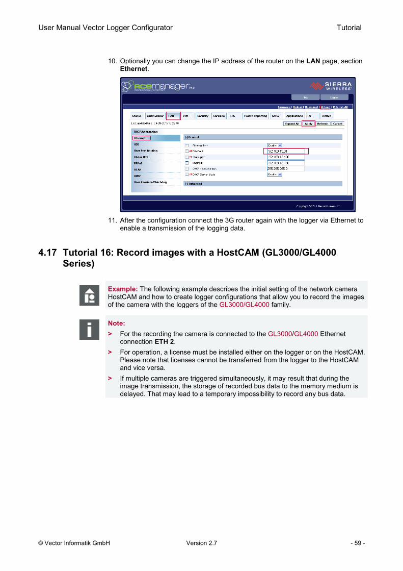
User Manual Vector Logger Configurator Tutorial
© Vector Informatik GmbH Version 2.7 - 59 -
10. Optionally you can change the IP address of the router on the LAN page, section Ethernet.
11. After the configuration connect the 3G router again with the logger via Ethernet to
enable a transmission of the logging data.
4.17 Tutorial 16: Record images with a HostCAM (GL3000/GL4000 Series)
Example: The following example describes the initial setting of the network camera HostCAM and how to create logger configurations that allow you to record the images of the camera with the loggers of the GL3000/GL4000 family.
Note: > For the recording the camera is connected to the GL3000/GL4000 Ethernet
connection ETH 2. > For operation, a license must be installed either on the logger or on the HostCAM.
Please note that licenses cannot be transferred from the logger to the HostCAM and vice versa.
> If multiple cameras are triggered simultaneously, it may result that during the image transmission, the storage of recorded bus data to the memory medium is delayed. That may lead to a temporary impossibility to record any bus data.
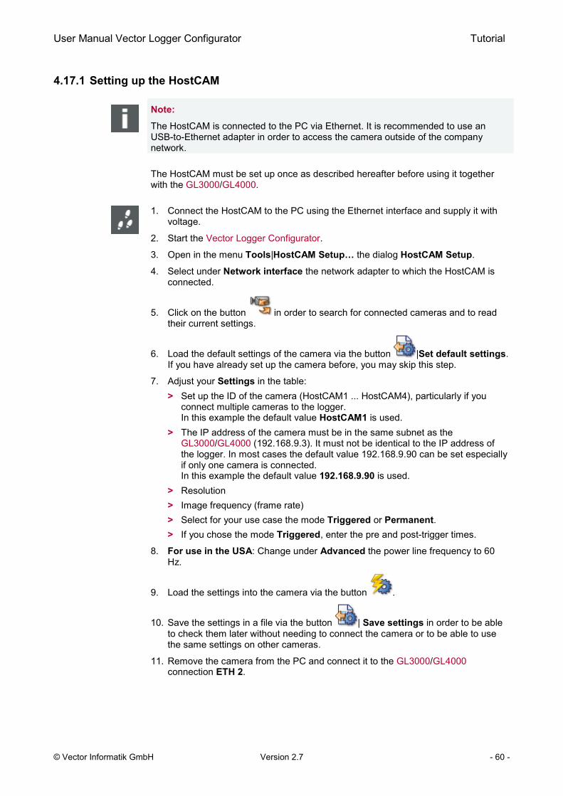
User Manual Vector Logger Configurator Tutorial
© Vector Informatik GmbH Version 2.7 - 60 -
4.17.1 Setting up the HostCAM
Note:
The HostCAM is connected to the PC via Ethernet. It is recommended to use an USB-to-Ethernet adapter in order to access the camera outside of the company network.
The HostCAM must be set up once as described hereafter before using it together with the GL3000/GL4000.
1. Connect the HostCAM to the PC using the Ethernet interface and supply it with voltage.
2. Start the Vector Logger Configurator.
3. Open in the menu Tools|HostCAM Setup… the dialog HostCAM Setup.
4. Select under Network interface the network adapter to which the HostCAM is connected.
5. Click on the button in order to search for connected cameras and to read their current settings.
6. Load the default settings of the camera via the button |Set default settings. If you have already set up the camera before, you may skip this step.
7. Adjust your Settings in the table: > Set up the ID of the camera (HostCAM1 ... HostCAM4), particularly if you
connect multiple cameras to the logger. In this example the default value HostCAM1 is used.
> The IP address of the camera must be in the same subnet as the GL3000/GL4000 (192.168.9.3). It must not be identical to the IP address of the logger. In most cases the default value 192.168.9.90 can be set especially if only one camera is connected. In this example the default value 192.168.9.90 is used.
> Resolution > Image frequency (frame rate) > Select for your use case the mode Triggered or Permanent. > If you chose the mode Triggered, enter the pre and post-trigger times.
8. For use in the USA: Change under Advanced the power line frequency to 60 Hz.
9. Load the settings into the camera via the button .
10. Save the settings in a file via the button | Save settings in order to be able to check them later without needing to connect the camera or to be able to use the same settings on other cameras.
11. Remove the camera from the PC and connect it to the GL3000/GL4000 connection ETH 2.

User Manual Vector Logger Configurator Tutorial
© Vector Informatik GmbH Version 2.7 - 61 -
4.17.2 Configuration of a Triggered Capturing
Example: The following example describes the configuration of a triggered capturing of images by a HostCAM in the Vector Logger Configurator. The capturing shall always be started when Panel Key 1 is pressed. The status of the HostCAM is displayed on LED2 and the triggering of the HostCAM on LED3.
Note: > Requirement
During the setup of the HostCAM, the Triggered mode has been set. > The triggers should be chosen so that there is enough time between two triggers
to allow the images of the last trigger to be transmitted. > During the image transmission, no other trigger signals can be received or
evaluated by the logger. > For each measurement of a trigger, the images are stored in one ZIP file.
1. Start the Vector Logger Configurator.
2. Create a new project via File|New Project… or load via File|Open Project… an existent project to which the image recording shall be added.

User Manual Vector Logger Configurator Tutorial
© Vector Informatik GmbH Version 2.7 - 62 -
Activation of the camera
3. Open the Hardware node in the tree view.
4. Click on HostCAM.
5. Activate the camera HostCAM1.
6. Set up the IP address of the HostCAM. The presetting 192.168.9.90 corresponds to the default setting of the first HostCAM. It can be changed as described above.
7. Choose the mode Triggered capturing.
8. Choose Marker message… (optional)
Configuration of a trigger event
9. Open the Logging Memory 1|Trigger node in the tree view.
10. Choose the mode Triggered logging.
11. Choose the trigger event Key and in the following dialog Panel Key 1.
12. Click in the column Action/HostCAM on […] in order to activate the HostCAM1 on this trigger.
13. Activate in the dialog Action Settings the HostCAM1 and Trigger capturing.
14. Close the dialog with [OK].
Configuration of a LED
15. Open the Output|LEDs node in the tree view.
16. Select at LED 2 the HostCAM status for the HostCAM1.
17. Select at LED 3 the HostCAM triggering for the HostCAM1.
18. Save the configuration on your PC.
19. Load the configuration into the logger as described in Tutorial 4.
Note: > The triggers should be triggered by activating the key in the way that there is
enough time between two triggers to allow the images of the last trigger to be transmitted.
> When triggered, the image data are transmitted from the camera to the logger. It is impossible to trigger further camera recordings during the transmission.
> For each camera recording, the images are stored in one ZIP file.

User Manual Vector Logger Configurator Tutorial
© Vector Informatik GmbH Version 2.7 - 63 -
4.17.3 Configuration of a Long-term Capturing
Example: The following example describes the configuration of a long-term capturing of images by a HostCAM in the Vector Logger Configurator. The capturing shall be started by Panel Key 3 and stopped by Panel Key 4. The status of the HostCAM is displayed on LED2. The running image capturing is displayed on LED 3.
Note: > Requirements:
> During the setup of the HostCAM, the Permanent mode has been set. > The picture resolution and image frame must be set low enough (e.g. 1 image
per second). > For each measurement (without an interruption), the images are stored in one ZIP
file. When the file reaches the size of 250 MB the capturing will be continued in a new ZIP file.
1. Start the Vector Logger Configurator.
2. Create a new project via File|New Project… or load via File|Open Project… an existent project to which the image recording shall be added.
Activation of the camera
3. Open the Hardware node in the tree view.
4. Click on HostCAM.
5. Activate the camera HostCAM1.
6. Set up the IP address of the HostCAM. The presetting 192.168.9.90 corresponds to the default setting of the first HostCAM. It can be changed as described above.
7. Choose the mode Long-term capturing.
Configuration of start/stop events
8. Open the Logging Memory 1|Trigger node in the tree view.
9. Choose the mode Conditioned long-term logging.
10. Choose the trigger event Key and in the following dialog Panel Key 3.
11. Click in the column Action/HostCAM on […] in order to activate the HostCAM1 on this trigger.
12. Activate in the dialog Action Settings the HostCAM1 and Start capturing.
13. Close the dialog with [OK].
14. Choose again the trigger event Key and in the following dialog Panel Key 4.
15. Click in the column Action/HostCAM on […].
16. Activate in the dialog Action Settings the HostCAM1 and Stop capturing.
17. Close the dialog with [OK].

User Manual Vector Logger Configurator Tutorial
© Vector Informatik GmbH Version 2.7 - 64 -
Configuration of a LED
18. Open the Output|LEDs node in the tree view.
19. Select at LED 2 the HostCAM status for the HostCAM1.
20. Select at LED 3 the HostCAM trigger for the HostCAM1.
21. Save the configuration on your PC.
22. Load the configuration into the logger as described in Tutorial 4.
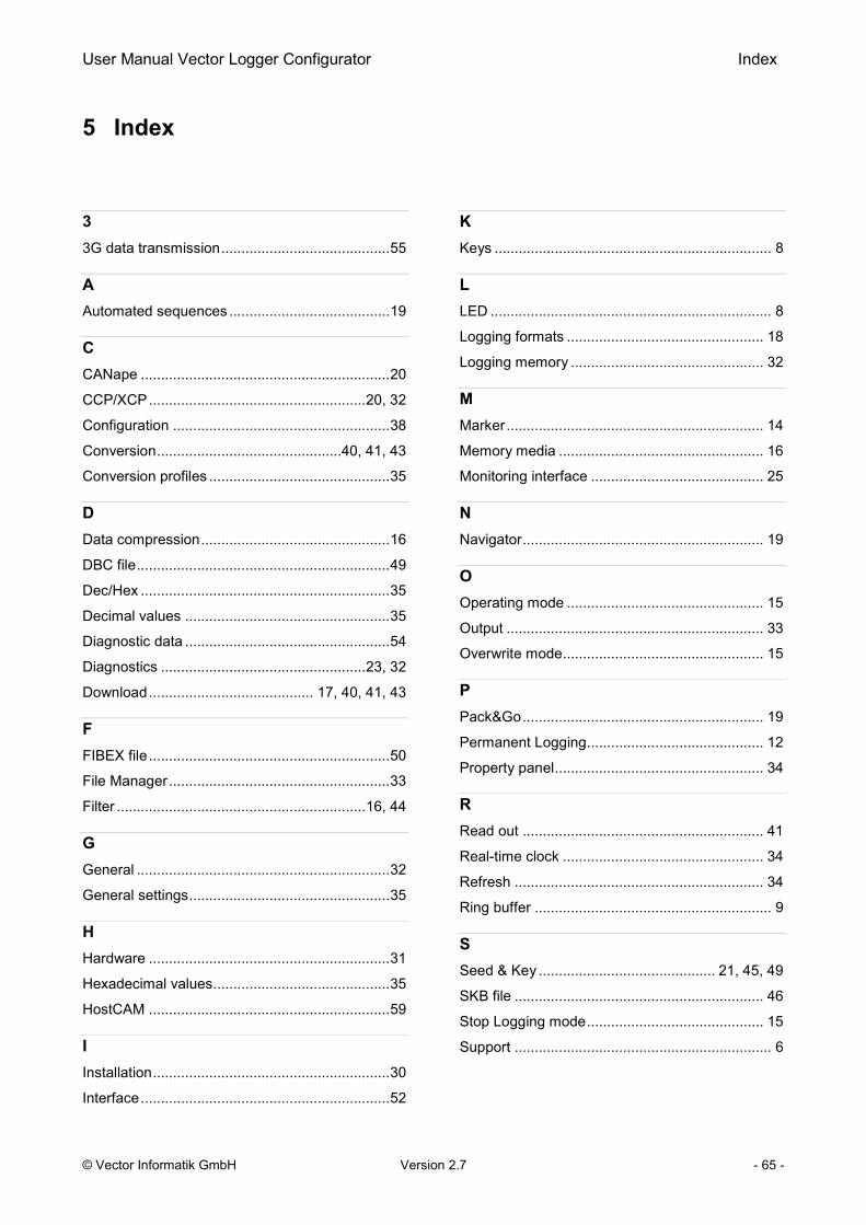
User Manual Vector Logger Configurator Index
© Vector Informatik GmbH Version 2.7 - 65 -
5 Index
3
3G data transmission .......................................... 55
A
Automated sequences ........................................ 19
C
CANape .............................................................. 20
CCP/XCP ...................................................... 20, 32
Configuration ...................................................... 38
Conversion ..............................................40, 41, 43
Conversion profiles ............................................. 35
D
Data compression ............................................... 16
DBC file ............................................................... 49
Dec/Hex .............................................................. 35
Decimal values ................................................... 35
Diagnostic data ................................................... 54
Diagnostics ................................................... 23, 32
Download ......................................... 17, 40, 41, 43
F
FIBEX file ............................................................ 50
File Manager ....................................................... 33
Filter .............................................................. 16, 44
G
General ............................................................... 32
General settings .................................................. 35
H
Hardware ............................................................ 31
Hexadecimal values ............................................ 35
HostCAM ............................................................ 59
I Installation ........................................................... 30
Interface .............................................................. 52
K
Keys ..................................................................... 8
L
LED ...................................................................... 8
Logging formats ................................................. 18
Logging memory ................................................ 32
M
Marker ................................................................ 14
Memory media ................................................... 16
Monitoring interface ........................................... 25
N
Navigator ............................................................ 19
O
Operating mode ................................................. 15
Output ................................................................ 33
Overwrite mode .................................................. 15
P
Pack&Go ............................................................ 19
Permanent Logging ............................................ 12
Property panel .................................................... 34
R
Read out ............................................................ 41
Real-time clock .................................................. 34
Refresh .............................................................. 34
Ring buffer ........................................................... 9
S
Seed & Key ............................................ 21, 45, 49
SKB file .............................................................. 46
Stop Logging mode ............................................ 15
Support ................................................................ 6

User Manual Vector Logger Configurator Index
© Vector Informatik GmbH Version 2.7 - 66 -
T
Toolbar .......................................................... 34, 35
Tree View ............................................................ 31
Trigger.....................................................10, 11, 44
Tutorial ................................................................ 37
U
Upload .................................................... 17, 41, 43
X
XCP/CCP ..................................................... 45, 49
XCP/CCP license ............................................... 48


More Information
> News > Products > Demo Software > Support > Training Classes > Addresses
www.vector.com